

Graco SaniForce Series, SaniForce 25E650, SaniForce 25E651, SaniForce 25M879, SaniForce 25E030 Instructions And Parts
Page 1
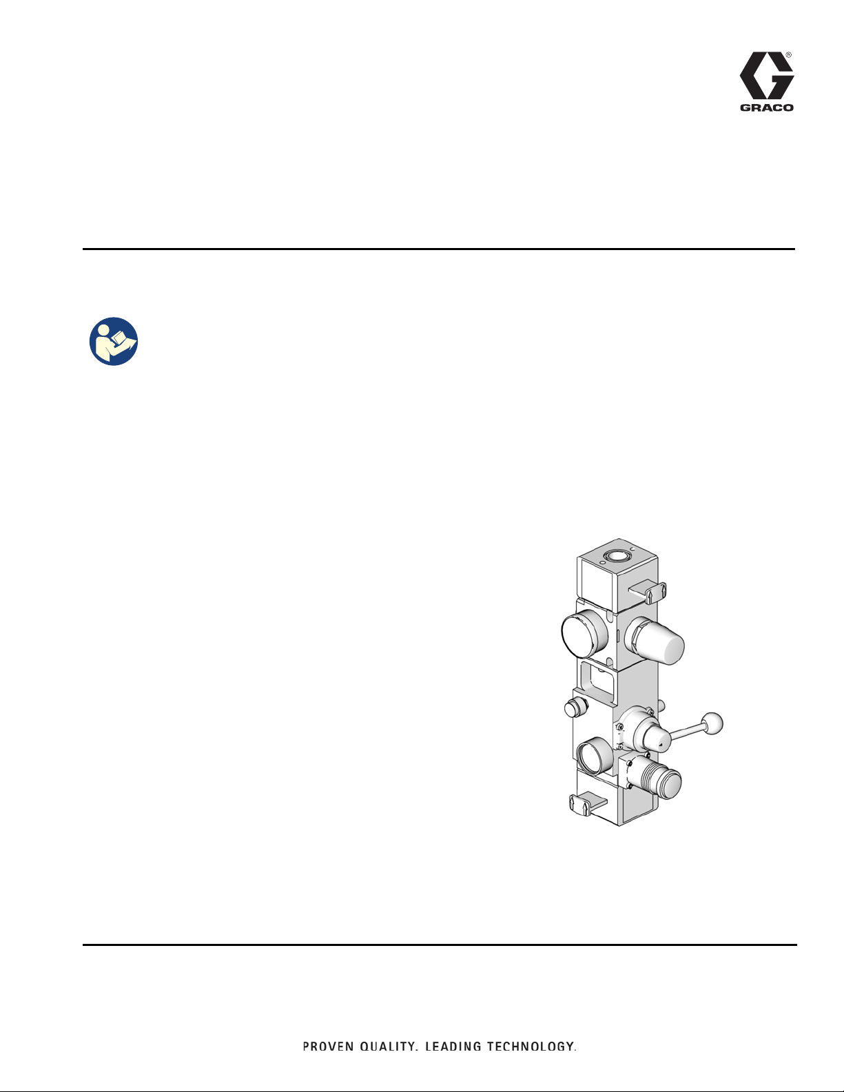
Instructions-Parts
SaniForce
Integrated Air Controls for use with Sanitary Supply Systems.
For professional use only.
Important Safety Instructions
Read all warnings and instructions in this manual.
Save these instructions.
See page 2 for Model information.
Air Controls
Integrated Air Controls
3A5800C
EN
ti10438a
Page 2

Contents
Contents
Contents . . . . . . . . . . . . . . . . . . . . . . . . . . . . . . . . . . 2
Models . . . . . . . . . . . . . . . . . . . . . . . . . . . . . . . . . . . 3
Integrated Air Controls . . . . . . . . . . . . . . . . . . . . . . 4
Pressure Relief Procedure . . . . . . . . . . . . . . . . . 4
Disassembly . . . . . . . . . . . . . . . . . . . . . . . . . . . . 4
Replace Director Valve . . . . . . . . . . . . . . . . . . . . 5
Replace Air Motor Regulator . . . . . . . . . . . . . . . . 5
Replace Ram Air Regulator . . . . . . . . . . . . . . . . 6
Reassembly . . . . . . . . . . . . . . . . . . . . . . . . . . . . 6
Parts . . . . . . . . . . . . . . . . . . . . . . . . . . . . . . . . . . . . . 7
Integrated Air Controls . . . . . . . . . . . . . . . . . . . . . 7
Pneumatic Schematic . . . . . . . . . . . . . . . . . . . . . . . 8
Integrated Air Control Module 25M879, 25E030 . 8
Integrated Air Control Module 25E650, 25E651 .9
Graco Standard Warranty . . . . . . . . . . . . . . . . . . . 10
Graco Information . . . . . . . . . . . . . . . . . . . . . . . . . 10
2 3A5800C
Page 3

Models
Air Controls
Model
No. Description
Air Controls for SPU 5 gal (20 l) and SDU 55 gal (208 l) Sanitary
25M879
25E030 Air Controls for SDU 55 gal (208 l) Sanitary Supply Systems,
25E650 Air Controls for SDU 55 gal (208 l) Sanitary Supply Systems,
25E651 Air Controls for SDU 55 gal (208 l) Sanitary Supply Systems,
Supply Systems, Carbon Steel Frame, Static Seal
Stainless Steel Frame, Static Seal
Stainless Steel Frame, Inflatable Seal
Carbon Steel Frame, Inflatable Seal
Models
Maximum
Regulated
Working
Pressure
psi (MPa, bar) Air Inlet Size
100 (0.7, 7) 3/4 npt(f)
100 (0.7, 7) 3/4 npt(f)
100 (0.7, 7) 3/4 npt(f)
100 (0.7, 7) 3/4 npt(f)
3A5800C 3
Page 4

Integrated Air Controls
Integrated Air Controls
Follow the Pressure Relief Procedure whenever you see
this symbol.
WARNING
PRESSURIZED FLUID HAZARD
This equipment stays pressurized until pressure is
relieved manually. To help prevent serious injury from
moving parts, or from pressurized fluid, such as
splashing in the eyes or on skin, follow the Pressure
Relief Procedure when you stop pumping and before
you clean, check, or service the equipment.
PERSONAL PROTECTIVE EQUIPMENT
Wear appropriate protective equipment when in the
work area to help prevent serious injury, including eye
injury or hearing loss.
Disassembly
WARNING
PRESSURIZED FLUID HAZARD
This equipment stays pressurized until pressure is
relieved manually. To help prevent serious injury from
moving parts, or from pressurized fluid, such as
splashing in the eyes or on skin, follow the Pressure
Relief Procedure when you stop pumping and before
you clean, check, or service the equipment.
1. Perform the pressure relief procedure.
2. Disconnect all hoses and tubing from existing air
control.
3. Remove four screws and washers from the
mounting bracket and remove the integrated air
controls.
25M879 (shown)
A2
Pressure Relief Procedure
1. Close the air motor slider valve (BH) and the main
air slider valve (BA).
NOTE: Both are relieving air valves.
2. Set the ram director valve (BD) to DOWN. The ram
will slowly drop.
3. Jog the ram director valve (BD) up and down to
bleed air from ram cylinder.
4. Open dispense valve or trigger gun to relieve pump
output pressure.
BF
D
BG
BC
BA
FIG. 1
The integrated air control includes:
BH
BI
BE
BD
BB
A1
4 3A5800C
Page 5

Integrated Air Controls
• Source air supply (A1): facility air supply to power
SPU.
• Air motor drive air (A2): air supply to drive pump
air motor.
• Main air slider valve (BA): turns air on and off to
the system. When closed, the valve relieves pressure downstream.
• Ram air regulator (BB): controls ram up and down
pressure and blowoff pressure.
• Ram air pressure gauge (BC): displays the air
pressure used to raise and lower the ram.
• Ram director valve (BD): controls ram direction.
• Air motor regulator (BE): controls air pressure to
motor.
• Air motor pressure gauge (BF): displays the air
pressure used to drive the air motor.
• Blowoff button (BG): turns air on and off to push
the platen out of an empty pail.
• Air motor slider valve (BH): turns air on and off to
the air motor. When closed, the valve relieves air
trapped between it and the air motor. Push the valve
in to shutoff.
• Air motor safety relief valve (BI): prevents overpressurization of air motor air supply.
Replace Director Valve
Numbers in parentheses refer to FIG. 2.
1. Disassemble the air control. See Disassembly,
page 4.
2. Remove screws (4a) and take off director valve.
3. Remove spring (4c), valve plate (4d), and o-ring
(4b).
7. Attach new director valve with screws (4a). Tighten
screws until snug.
4g
4f
4e
4b
4d
4c
4
4a
ti10952a
FIG. 2
Replace Air Motor Regulator
Numbers in parentheses refer to Parts, page 7.
1. Disassemble the air control. See Disassembly,
page 4.
2. Disconnect air motor hosing and fittings.
3. Remove two screws (9a) and take off the shutoff
valve (3) at top of module. If your supply system has
an air solenoid, it can remain attached to the shutoff
valve.
4. Remove two screws (9b) and take off the air motor
regulator (6).
5. Attach new regulator to manifold. Orient so the
gauge lines up with the gauge on the ram air regulator and the direction of flow arrow points up. Tighten
screws until snug. Recommend using thread locker
Loctite 220 or equivalent.
Note the orientation of the director valve plate when
you remove it. The opening should be on the opposite side (left) of the lever.
4. Remove and discard pin (4g) and four valve seats
(4e) with o-rings (4f).
5. Insert new valve seats (4e) with o-rings (4f) and new
pin.
6. Insert new director valve plate (4d, see Note above)
spring (4c), and o-ring (4b).
3A5800C 5
6. Reattach shutoff valve (3) at top of regulator. Make
sure that o-ring (5) is in place on valve (3).
Page 6

Integrated Air Controls
Replace Ram Air Regulator
Numbers in parentheses refer to Parts, page 7.
1. Disassemble the air control. See Disassembly,
page 4.
2. Remove four screws (7a) and take off the ram air
regulator (7).
3. Replace o-rings (7b) on back side of regulator.
4. Attach new air regulator to manifold. Use index pin
for correct orientation. Tighten screws until snug.
Reassembly
1. Using four screws and washers, attach the integrated air controls to the mounting bracket. See FIG.
1.
2. Attach the ram up, ram down, and blowoff air lines
as shown in Figure FIG. 3.
(BI) safety
relief port
Ram up
Blowoff
Auxiliary
air supply port
ti10778a
FIG. 3
3. Attach all other hoses and replace shrouds.
4. If replacing entire control assembly, install the
safety relief valve (BI) from previous control assembly.
Ram down
6 3A5800C
Page 7

Parts
Parts
Integrated Air Controls
3
5
17*
9a
13
9b
8
14
5
3
* Ref 17 must be ordered separately, based on working
pressure for installed pump, or re-used from existing
control (if it is being replaced).
7b
5
1
10
9
6
11
4b
4
4a
7a
7
ti10774a
Models 25M879, 25E030, 25E650,
25E651
Ref. Part Description
1 - - - MANIFOLD
3 VALVE, shutoff (includes o-rings
and screws)
121108 models 25M879, 25E030
16Y167 models 25E650, 25E651
4 VALVE, director (includes 4a and
4b, plus all parts shown in F
121107 models 25M879, 25E030
16Y157 models 25E650, 25E651
4a - - - SCREW
4b - - - O-RING
5 121110 O-RING, buna
6 255651 REGULATOR, air motor (includes
regulator, o-ring, and screws)
7 REGULATOR, ram (includes 7a and
7b)
121106 models 25M879, 25E651
17W740 models 25E030, 25E650
7a - - - SCREWS
7b - - - O-RING
8 121109 VALVE, blowoff (includes valve and
push button)
9 121112 SCREW, cap, socket head
1/4-20 x 5/8
10 517449 MUFFLER
11 100721 PLUG, pipe, auxiliary air supply
13 C36260 GAUGE, air pressure, 0-160 psi
(0-1.1 MPa, 0-11 bar)
14 GAUGE, air pressure,
C36260 0-160 psi, models 25M879, 25E651
17W903 0-60 psi, models 25E030, 25E650
15 113318 FITTING, elbow, plug-in (not shown,
25M879 only)
16 15V954 LABEL, valve, shutoff, air control
(not shown)
17* VALVE, Air motor safety relief
120306 85 psi
103347 100 psi
114003 130 psi
IG. 2)
Qty
.
1
2
1
4
1
3
1
1
4
2
1
6
1
1
1
1
2
1
1
3A5800C 7
Page 8

Pneumatic Schematic
Pneumatic Schematic
Integrated Air Control Module 25M879, 25E030
INTEGRATED AIR
CONTROL MODULE
Pump Pressure
Regulator
Air Motor
Shutoff
MAIN
AIR IN
Ram Pressure
Regulator
Air Pressure
Relief Valve
Ram Directional
Control Valve
UP
DOWN
Pump Air
Motor
Ram Down
Blow Off
Valve
Platen
Ram Up
8 3A5800C
Page 9

Integrated Air Control Module 25E650, 25E651
Pneumatic Schematic
MAIN AIR
SUPPLY
MAIN AIR
SHUTOFF
AIR PRESSURE
RELIEF VALVE
SEAL PRESSURE
REGULATOR
PUMP PRESSURE
REGULATOR
RAM PRESSURE
REGULATOR
AIR PRESSURE
RELIEF VALVE
AIR PRESSURE
RELIEF VALVE
AIR MOTOR
SHUTOFF
RAM DIRECTIONAL
CONTROL VALVE
INFLATABLE
SEAL VALVE
UP
HOLD
DOWN
NEEDLE
VALVE
BLOW OFF
VALVE
PUMP
(AIR MOTOR)
BLOW OFF
(PLATEN)
RAM UP
(CONNECT TUBING TO
CYLINDER BOTTOM)
RAM DOWN
(CONNECT TUBING TO
CYLINDER TOP)
3A5800C 9
Page 10

Graco Standard Warranty
Graco warrants all equipment referenced in this document which is manufactured by Graco and bearing its name to be free from defects in
material and workmanship on the date of sale to the original purchaser for use. With the exception of any special, extended, or limited warranty
published by Graco, Graco will, for a period of twelve months from the date of sale, repair or replace any part of the equipment determined by
Graco to be defective. This warranty applies only when the equipment is installed, operated and maintained in accordance with Graco’s written
recommendations.
This warranty does not cover, and Graco shall not be liable for general wear and tear, or any malfunction, damage or wear caused by faulty
installation, misapplication, abrasion, corrosion, inadequate or improper maintenance, negligence, accident, tampering, or substitution of
non-Graco component parts. Nor shall Graco be liable for malfunction, damage or wear caused by the incompatibility of Graco equipment with
structures, accessories, equipment or materials not supplied by Graco, or the improper design, manufacture, installation, operation or
maintenance of structures, accessories, equipment or materials not supplied by Graco.
This warranty is conditioned upon the prepaid return of the equipment claimed to be defective to an authorized Graco distributor for verification of
the claimed defect. If the claimed defect is verified, Graco will repair or replace free of charge any defective parts. The equipment will be returned
to the original purchaser transportation prepaid. If inspection of the equipment does not disclose any defect in material or workmanship, repairs
will be made at a reasonable charge, which charges may include the costs of parts, labor, and transportation.
THIS WARRANTY IS EXCLUSIVE, AND IS IN LIEU OF ANY OTHER WARRANTIES, EXPRESS OR IMPLIED, INCLUDING BUT NOT
LIMITED TO WARRANTY OF MERCHANTABILITY OR WARRANTY OF FITNESS FOR A PARTICULAR PURPOSE.
Graco’s sole obligation and buyer’s sole remedy for any breach of warranty shall be as set forth above. The buyer agrees that no other remedy
(including, but not limited to, incidental or consequential damages for lost profits, lost sales, injury to person or property, or any other incidental or
consequential loss) shall be available. Any action for breach of warranty must be brought within two (2) years of the date of sale.
GRACO MAKES NO WARRANTY, AND DISCLAIMS ALL IMPLIED WARRANTIES OF MERCHANTABILITY AND FITNESS FOR A
PARTICULAR PURPOSE, IN CONNECTION WITH ACCESSORIES, EQUIPMENT, MATERIALS OR COMPONENTS SOLD BUT NOT
MANUFACTURED BY GRACO. These items sold, but not manufactured by Graco (such as electric motors, switches, hose, etc.), are subject to
the warranty, if any, of their manufacturer. Graco will provide purchaser with reasonable assistance in making any claim for breach of these
warranties.
In no event will Graco be liable for indirect, incidental, special or consequential damages resulting from Graco supplying equipment hereunder, or
the furnishing, performance, or use of any products or other goods sold hereto, whether due to a breach of contract, breach of warranty, the
negligence of Graco, or otherwise.
FOR GRACO CANADA CUSTOMERS
The Parties acknowledge that they have required that the present document, as well as all documents, notices and legal proceedings entered into,
given or instituted pursuant hereto or relating directly or indirectly hereto, be drawn up in English. Les parties reconnaissent avoir convenu que la
rédaction du présente document sera en Anglais, ainsi que tous documents, avis et procédures judiciaires exécutés, donnés ou intentés, à la suite
de ou en rapport, directement ou indirectement, avec les procédures concernées.
Graco Information
For the latest information about Graco products, visit www.graco.com.
TO PLACE AN ORDER, contact your Graco distributor or call to identify the nearest distributor.
Phone: 612-623-6921 or Toll Free: 1-800-328-0211 Fax: 612-378-3505
All written and visual data contained in this document reflects the latest product information available at the time of publication.
GRACO INC. AND SUBSIDIARIES • P.O. BOX 1441 • MINNEAPOLIS MN 55440-1441 • USA
Copyright 2018, Graco Inc. All Graco manufacturing locations are registered to ISO 9001.
Graco reserves the right to make changes at any time without notice.
For patent information, see www.graco.com/patents.
Original instructions. This manual contains English. MM 3A5800
Graco Headquarters: Minneapolis
International Offices: Belgium, China, Japan, Korea
www.graco.com
Revision C, August 2019
 Loading...