

Page 1
Operation
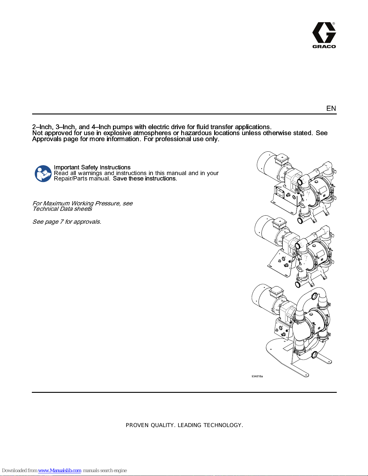
SaniForce 2150e, 3000e, 4000e,
Electric-Operated Diaphragm Pump
2–Inch, 3–Inch, and 4–Inch pumps with electric drive for fluid transfer applications.
Not approved for use in explosive atmospheres or hazardous locations unless otherwise stated. See
Approvals page for more information. For professional use only.
Important Safety Instructions
Read all warnings and instructions in this manual and in your
Repair/Parts manual.
For Maximum Working Pressure, see
Technical Data sheets
See page 7 for approvals.
Save these instructions.
3A5132F
EN
PROVEN QUALITY. LEADING TECHNOLOGY.
Page 2
Contents
Related Manuals ................................................ 2
Warnings ........................................................... 3
Configuration Number Matrix............................... 6
Ordering Information........................................... 8
Installation.......................................................... 9
General Information ..................................... 9
Tighten Clamps Before First Use .................. 9
Tips to Reduce Cavitation............................. 9
Mount the 2150T Pump................................ 12
Mount the HS Pump..................................... 13
Ground The System..................................... 14
Air Line........................................................15
Fluid Supply Line .........................................15
Fluid Outlet Line...........................................15
Electrical Connections .................................. 16
Leak Sensor Wiring...................................... 18
Compressor Wiring......................................19
Operation ........................................................... 20
Initial Configuration (AC with VFD)................ 20
Related Manuals
Manual Number Title
Sanitize the Pump Before First Use............... 20
Transfer Mode Vs. Low Pulsation
Mode............................................. 20
Start and Adjust the Pump............................ 20
Pressure Relief Procedure............................ 21
Pump Shutdown .......................................... 21
VFD Operation...................................................22
VFD Control Panel....................................... 22
Adjust the Speed ......................................... 22
Maintenance ...................................................... 23
Maintenance Schedule ................................. 23
Lubrication...................................................23
Tighten Connections ....................................23
Flushing and Storage...................................23
Performance Data .............................................. 24
Dimensions (2150T Pump) .................................. 28
Dimensions (3000HS Flapper Pumps) ................. 31
Technical Data ................................................... 33
3A5133 SaniForce™ 2150e, 3000e, 4000e, Electric-Operated Diaphragm Pump,
Repair/Parts
2
3A5132F
Page 3

Warnings
Warnings
The following warnings are for the setup, use, grounding, maintenance, and repair of this equipment. The
exclamation point symbol alerts you to a general warning and the hazard symbols refer to procedure-specific
risks. When these symbols appear i n the body of this manual or on warning labels, refer back to these
Warnings. Product-specific hazard symbols and warnings not covered in this section may appear throughout
the body of this manual where appli cable.
WARNING
ELECTRIC SHOCK HAZARD
This equipment must be grounded. Improper grounding, setup, or usage of the system can
cause electric shock.
• Turn off and remove power before disconnecting any cables and before servicing or installing
equipment. For cart-mounted models, unplug the power cord. For all other units, disconnect
power at the main switch.
• Connect only to grounded power source.
• All electrical wiring must be done by a qualified electrician and comply with all local codes
and regulations.
• Wait five minutes for capacitor discharge b efore opening equipment.
FIRE AND EXPLOSION HAZARD
Flammable fumes, such as solvent and paint fumes, in
or solvent flowing through the equipment can cause static sparking. To help prevent fire and
explosion:
• Use equipment only in well ventilated area.
• Eliminate all ignition sources; such as pilot lights, cigarettes, portable electric lamps, and
plastic drop cloths (po tential static arc).
• Ground all equipment in the work area. See
• Keep work area free of debris, including solvent, rags and gasoline.
• Do not plug or unplug power cords, or turn power or light switches on or off when flammable
fumes are present.
• Use only grounded hoses.
•
Stop operation immediately
equipment until you identify and correct the problem.
• Keep a working fire extinguisher in the work area.
Static charge may build up on plastic parts during cleaning and could discharge and ignite
flammable vapors. To help prevent fire and explosion:
• Clean plastic parts only in well vent ilated area.
• Donotcleanwithadrycloth.
• Do not operate electrostatic guns in equipment work area.
if static sparking occurs or you feel a shock.Do not use
Grounding
work area
instructions.
canigniteorexplode.Paint
3A5132F 3
Page 4
Warnings
WARNING
PRESSURIZED EQUIPMENT HAZARD
Fluid from the equipment, leaks, or rup tured components can splash in the eyes or on skin
and cause serious injury.
• Follow the
cleaning, checking, or servicing equipment.
• Tighten all fluid connections before operating the equipment.
• Check hoses, tubes, and couplings daily. Replace worn or damaged parts immediately.
EQUIPMENT MISUSE HAZARD
Misuse can cause death or serious injury.
• Do not operate the unit when fatigued or under the influence of drugs o r alcohol.
• Do not exceed the maximum working pressure or temperature rating of the lowest rated
system component. See
• Use fluids and solvents that are compatible with equipment wetted parts. See
in all equipment manuals. Read fluid and solve nt manufacturer’s warnings. For complete
information about your material, request Safety Data Sheet (SDS) from distributor or retailer.
• Turn off all equipment and follow the
• Check equipment daily. Repair or replace worn or damaged parts immediately with genuine
manufacturer’s replacement parts only.
• Do not alter or modify equipment. Alterations or modifications may void agency approvals
and create safety hazards.
• Make sure all equipment is rated and approved for the environment in which you are using it.
• Use equipment only for its intended purpose. Call your distributor for information.
• Route hoses and cables away from traffic areas, sharp edges, moving parts, and hot surfaces.
• Do not kink or over bend hoses or use hoses to pull equipment.
• Keep children and animals away from work area.
• Comply with all applicable safety regulations.
Pressure Relief Procedure
Technical Data
when you stop spraying/dispensing and before
in all equipment manuals.
Technical Data
Pressure Relief Procedure
when equipment is not in use.
PRESSURIZ E D ALUMINUM PARTS HAZARD
Use of fluids that are incompatible with aluminum in pressurized equipment can cause serious
chemical reaction and equipment rupture. Failure to follow this warning can result in death,
serious injury, or property damage.
• Do not use 1,1,1-trichloroethane, methylene chloride, other halogenated hydrocarbon
solvents or fluids containing such solvents.
• Do not use chlorine bleach.
• Many other fluids may contain chemicals that can react with aluminum. Contact your material
supplier for compatibility.
4
3A5132F
Page 5
Warnings
WARNING
THERMAL EXPANSION HAZARD
Fluidssubjectedtoheatinconfinedspaces,includinghoses,cancreatearapidriseinpressure
due to the thermal expansion. Over-pressurization can result in equipment rupture and serious
injury.
• Openavalvetorelievethefluidexpansionduringheating.
• Replace hoses proactively at regular intervals based on your operating conditions.
PLASTIC PARTS CLEANING SOLVENT HAZARD
Many solvents can degrade plastic parts and cause them to fail, which could cause serious
injury or property damage.
• Use only compatible water-based solvents to clean plastic structural or pressure-containing
parts.
•See
Technical Data
solvent manufacturer’s Safety Data Sheet (SDS) and recommendations.
in this and all other equipment instruction manuals. Read fluid and
TOXIC FLUID OR FUMES HAZARD
Toxic fluids or fumes can cause serious injury or death if splashed in the eyes or on skin,
inhaled, or swallowed.
• Read Safety Data Sheet (SDS) to know the specific hazards of the fluids you are using.
• Store hazardous fluid in approved containers, and dispose of i t according to applicable
guidelines.
BURN HAZARD
Equipment surfaces and fluid that’s heated can become very hot during operation. To avoid
severe burns:
• Do not touch hot fluid or equipme nt.
PERSONAL PROTECTI V E EQUIPMENT
Wear appropriate protective equipment when in the work area to help prevent serious injury,
including eye injury, hearing loss, inhalation of toxic fumes, and burns. This protective
equipment includes but is not limited to:
• Protective eyewear, and hearing protection.
• Respirators, protective clothing, and glo ves as recommended by the fluid and solvent
manufacturer.
3A5132F 5
Page 6
Configuration Number Matrix
Configuration Number Matrix
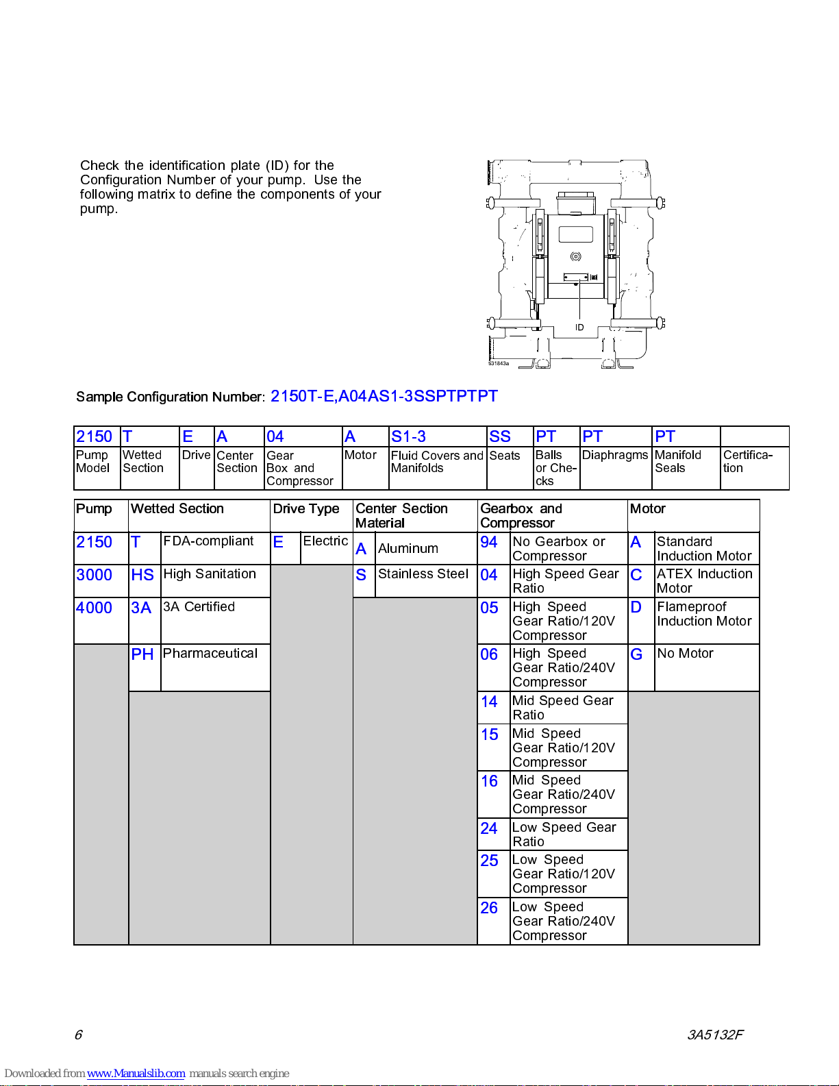
Check the identification plate (ID) for the
Configuration Number of your pump. Use the
following matrix to define the components of your
pump.
Sample Configuration Number:
2150
Pump
Model
Pump
2150
3000 HS
4000 3A
TEA
Wetted
Section
Wetted Section
T
PH
Drive
Center
Section
FDA-compliant
High San
3A Certified
Pharmaceutical
itation
2150T-E,A04AS1-3SSPTPTPT
04
Gear
Box and
Compressor
Drive Type
Electric
E
A
Motor
S1-3 SS
Fluid Covers and
Manifolds
Center Section
Material
Aluminu
A
Stainle
S
m
ss Steel
PT PT PT
Seats
Gearbox and
Compressor
94
04
05
06
14
15
16
24
25
26
Balls
or Che-
cks
No Gearbox or
Compressor
High Spe
Ratio
High Speed
Gear Ratio/120V
Compressor
High Speed
Gear Ratio/240V
Compressor
peed Gear
Mid S
Ratio
Mid Speed
Gear Ratio/120V
Compressor
Mid Speed
Gear Ratio/240V
Compressor
w Speed Gear
Lo
Ratio
Low Speed
Gear Ratio/120V
Compressor
Low Speed
Gear Ratio/240V
Compressor
Diaphragms
ed Gear
Manifold
Seals
Motor
Standard
A
Induction Motor
ATEX Induction
C
Motor
Flameproof
D
Induction Motor
No Motor
G
Certifica-
tion
6 3A5132F
Page 7
Configuration Number Matrix
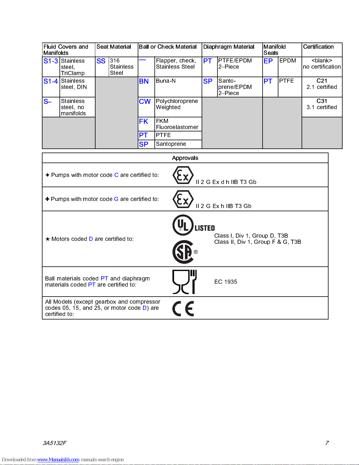
Fluid Covers and
Manifolds
S1-3
S1-4
S–
Stainless
steel,
TriClamp
Stainless
steel, DIN
Stainless
steel, no
manifolds
Seat Material Ball or Check Material
SS
316
Stainless
Steel
—
BN
CW
FK
PT
SP
✦ Pumps with motor code C are certified to:
✚ Pumps with motor code G arecertifiedto:
Flapper, check,
Stainless Steel
Buna-N
Polychloroprene
Weighted
FKM
Fluoroelastomer
PTFE
Santoprene
Approvals
Diaphragm Material
PTFE/EPDM
PT
2–Piece
Santo-
SP
prene/EPDM
2–Piece
II 2 G Ex d h IIB T3 Gb
II2GExhIIBT3Gb
Manifold
Seals
EPDM <blank>
EP
PTFE
PT
Certification
no certification
C21
2.1 certified
C31
3.1 certified
★ Motors coded D arecertifiedto:
Ball materials coded PT and diaphragm
materials coded PT are certified to:
All Models (except gearbox and compressor
codes 05, 15, and 25, or motor code D)are
certified to:
Class I, Div 1, Group D, T3B
Class II, Div 1, Group F & G, T3B
EC 1935
3A5132F
7
Page 8
Ordering Information
Ordering Information
To Find Your Nearest Distributor
1. Visit www.graco.com.
2. Click on
To Specify the Configuration of a New Pump
Please call your distributor.
OR
Where to Buy
and use the
Distributor Locator.
Use the
Online Diaphragm Pump Selector Tool at www.graco.com.
To Order Replacement Parts
Please call your distributor.
Go to the
Process Equipment Page.
8 3A5132F
Page 9
Installation
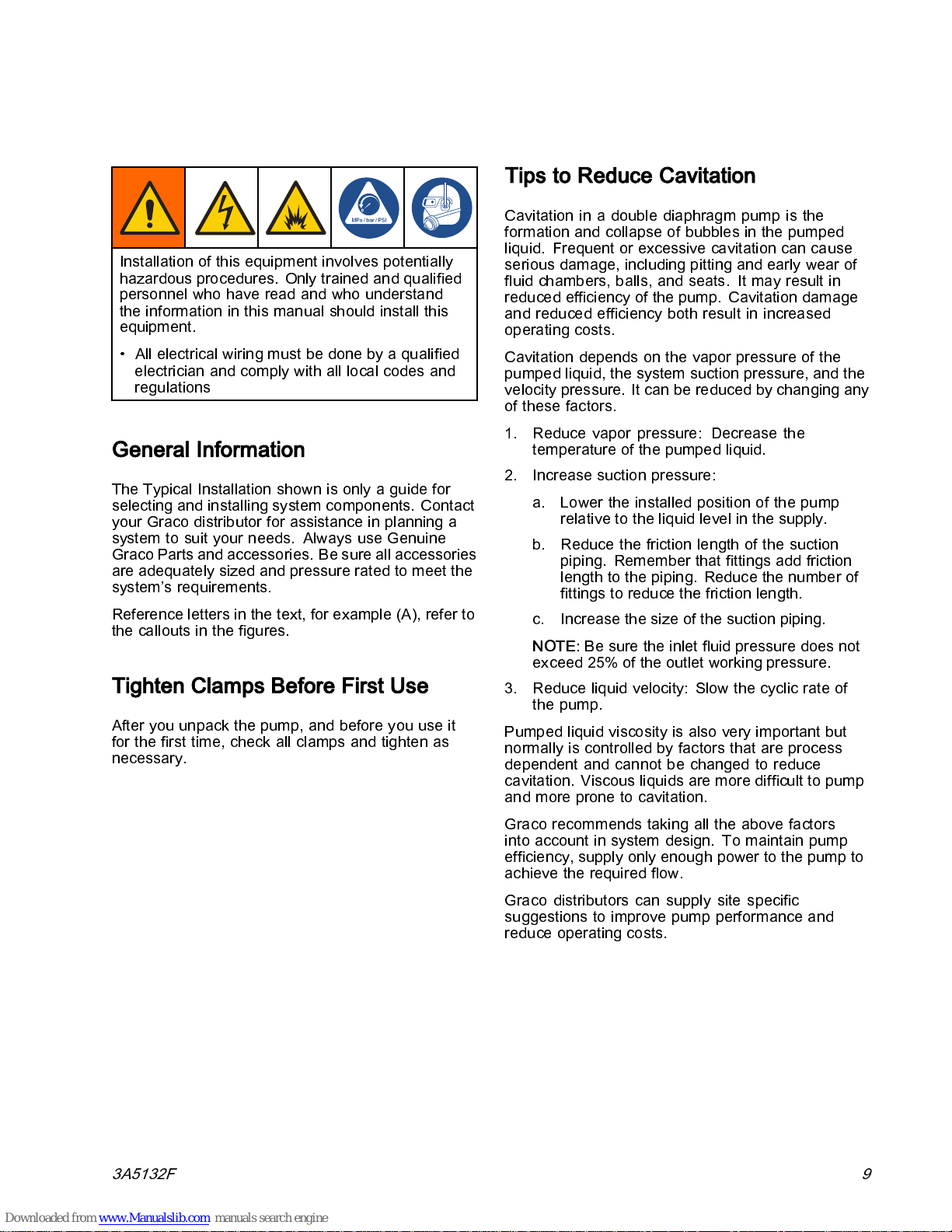
Installation of this equipment involves potentially
hazardous procedures. Only trained and qualified
personnel who have read and who understand
the information in this manual should install this
equipment.
• All electrical wiring must be done by a qualified
electrician and comply with all local codes and
regulations
General Information
The Typical Installation shown i s only a guide for
selecting and installing system components. Contact
your Graco distributor for assistance in planning a
system to suit your needs. Always use Genuine
Graco Parts and accessories. Be sure all accessories
are adequately sized and pressure rated to meet the
system’s requirements.
Reference letters in the text, for example (A), refer to
the callouts in the figures.
Tighten Clamps Before First Use
After you unpack the pump, and before you use it
for the first time, check all clamps and tighten as
necessary.
Installation
Tips to Reduce Cavitation
Cavitation in a double diaphragm pump is the
formation and collapse of bubbles in the pumped
liquid. Frequent or excessive cavitation can cause
serious damage, including pitting and early wear of
fluid chambers, balls, and seats. It may result in
reduced efficiency of the pump. Cavitation damage
and reduced efficiency both result in increased
operating costs.
Cavitation depends on the va por pressure of the
pumped liquid, the system suction pressure, and the
velocity pressure. It can be reduced by changing any
of these factors.
1. Reduce vapor pressure: Decrease the
temperature of the pumped liquid.
2. Increase suction pressure:
a. Lower the installed position of the pump
relative to the liquid level in the supply.
b. Reduce the friction length of the suction
piping. Remember that fit tings add friction
length to the piping. Reduce the number of
fittings to reduce the friction length.
c. Increase the size of the suction piping.
NOTE:
exceed 25% of the outlet working pressure.
3. Reduce liquid velocity: Slow the cyclic rate of
the pump.
Pumped liquid viscosity is also very important but
normally is controlled by factors that are process
dependent and cannot be changed to reduce
cavitation. Viscous liquids are more difficult to pump
and more prone to cavitation.
Be sure the inlet fluid pressure does not
3A5132F 9
Graco recommends taking all the above factors
into account in system design. To maintain pump
efficiency, supply only enough power to the pump to
achieve the required flow.
Graco distributors can supply site specific
suggestions to improve pump performan ce and
reduce operating costs.
Page 10

Installation
Figure 1 Typical Installation for pumps without a
compressor
System Component s Accessories / Components Not Supplied
B Fluid inlet port A* Power cord to VFD
C Fluid outlet port F* Grounded, flexible air supply line
D Mounting feet G Bleed-type master air valve
E Air inlet port H Air filter/regulator assembly
P Pump Ground J Master air valve (for accessories)
R Center section regulator K* Grounded, flexible fluid supply line
10 3A5132F
L Fluid drain valve (may be required for your
pump installation)
M
Fluid shutoff valve
N* Grounded, flexible fluid outlet line
* Required. Supplied by cus tomer.
Page 11
Installation
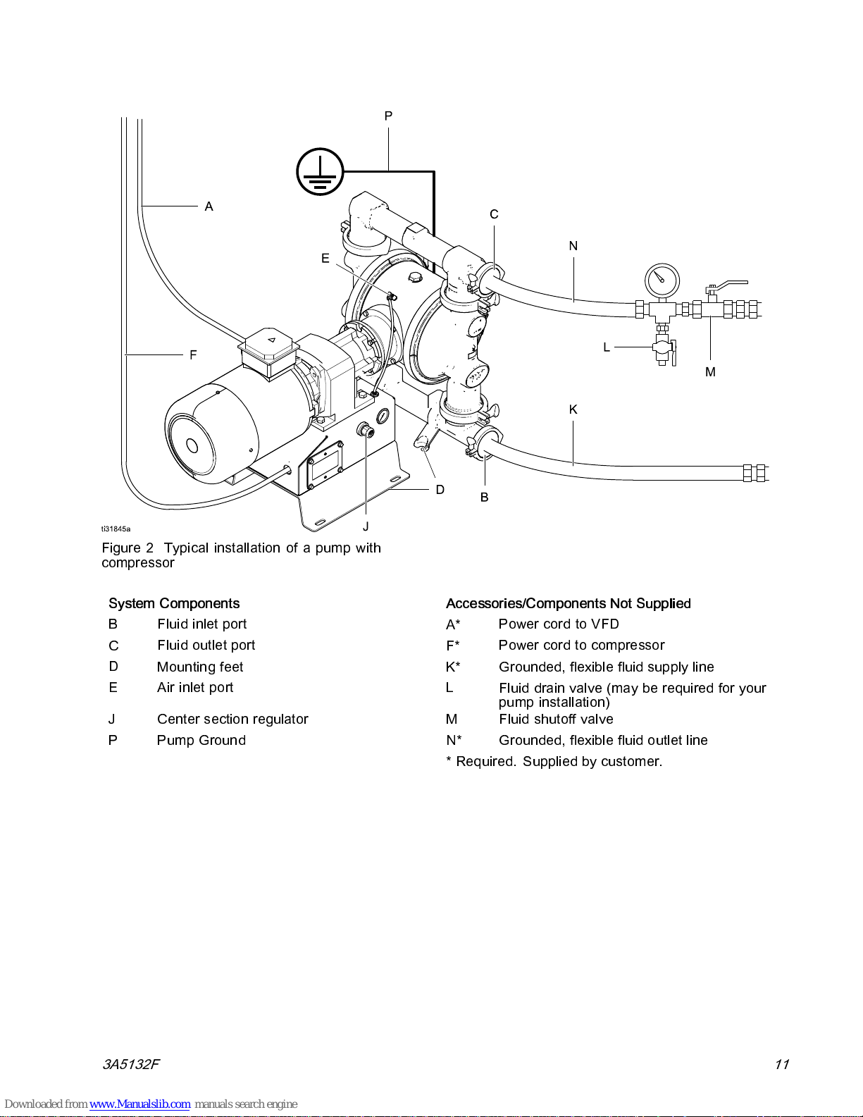
Figure 2 Typical installation of a pump with
compressor
System Components Accessories/Components Not Supplied
B Fluid inlet port
C
D
Fluid outlet port
Mounting feet K* Grounded, flexible fluid supply line
E Air inlet port L
A*
F*
Power cord to VFD
Power cord to compressor
Fluiddrainvalve(mayberequiredforyour
pump installation)
J
P
Center section regulator
Pump Ground N* Grounded, flexible fluid outlet line
M
Fluid shutoff valve
* Required. Supplied by customer.
3A5132F
11
Page 12
Installation
Mount the 2150T Pump
To avoid serious injury or death from toxic flu id or
fumes:
• Never move or lift a pum p under pressure. If
dropped, the fluid section may rupture. Always
follow the Pressure Relief Procedure, page 21,
before moving or lifting the pump.
• Do not expose pump or the plastic components
to direct sunlight for prolonged periods.
Prolonged exposure to UV radiation will degrade
natural polypropylene components of the pumps.
NOTICE
The pump is heavy. To prevent damage from
dropping, always use a lift to move the pump. Do
not use the manifolds to lift the pump. Use at least
two straps.
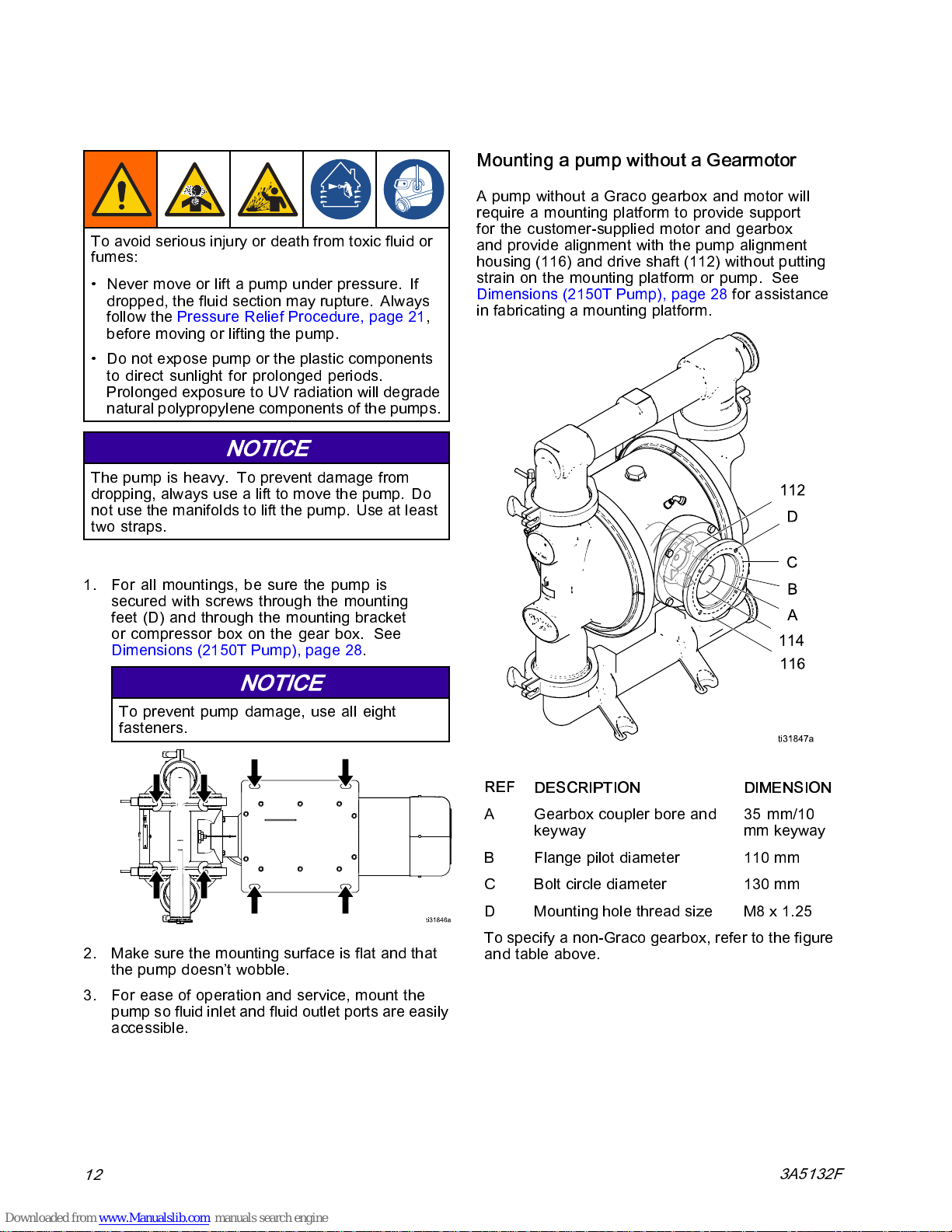
Mounting a pump without a Gearmotor
A pump without a Graco gearbox and motor will
require a mounting platform to provide support
for the customer-supplied motor and gearbox
and provide alignment with the pump alignment
housing (116) and drive shaft (112) without putting
strain on the mounting platform or pump. See
Dimensions (2150T Pump), page 28 for assistance
in fabricating a mounting platform.
1. For all mountings, be sure the pump is
d with screws through the mounting
secure
feet (D) and through the moun ting bracket
or comp
Dimensions (2150T Pump), page 28.
ressor box on t he gear box. See
NOTICE
vent pump damage, use all eight
To pre
fasteners.
2. Ma
3. Fo
ke sure the mounting surface is flat and that
the pump doesn’t wobble.
r ease of operation and servi ce, mount the
pump so fluid inlet and fluid outlet ports are easily
cessible.
ac
REF
A
B Flange pilot diameter 110 mm
C
D Mounting hole thread size M8 x 1.25
To specify a non-Graco gearbox, refer to the figure
and table above.
DESCRIPTION DIMENSION
Gearbox coupler bore and
keyway
Bolt circle diameter 130 mm
35 mm/10
mm keyway
12
3A5132F
Page 13

Mount the HS Pump
To avoid serious injury or death from toxic fluid or
fumes:
• Never move or lift a pump under pressure. If
dropped, the fluid section may rupture. Always
follow the Pressure Relief Procedure, page 21,
before moving or lifting the pump.
NOTICE
The pump is heavy. To prevent damage from
dropping, always use a lift to move the pump. Do
not use the manifolds to lift the pump. Use at least
two straps.
Installation
1. For all mountings, be sure the pump is secured
with screws through the moun ting bracket.
2. Make sure the mounti ng surface is flat and
that the pump base doesn’t wobble. See
Dimensions (3000HS Flapper Pumps), page 31.
NOTICE
To prevent pump damage, use all fasteners.
3. For ease of operation and service, mount the
pump so fluid inlet and fluid outlet ports are easily
accessible.
4. Attachthepumpbasetothemountingsurface.
3A5132F 13
Page 14

Installation
Ground The System
The equipment must be grounded to reduce the
risk of static sparking. Static sparking can cause
fumes to ignite or explode. Improper grounding
can cause electric shock.Grounding provides an
escape wire for the electrical current.
•
Always
described below.
•Followyou
ndtheentirefluidsystemas
grou
r local fire codes.
•
Air Line and Fluid hoses:
hoses with a maximum of 500 ft (150 m) combined
hose length to ensure grounding continuity. Check
electrical resistance of hoses. If total resistance
to ground exceeds 29 megohms, replace hose
immediately.
•
Fluid supply container:
•
Solvent pails used when flushing:
code. Use only conduc tive metal pails, placed
onagroundedsurface. Donotplacethepail
on a nonconductive surface, such as paper or
cardboard, which interrupts grounding continuity.
•
VFD:
Ground the variable frequency drive through
aproperconnectiontoapowersource.Referto
the VFD manual for grounding instructions.
Use only grounded
Follow local code.
Follow local
Before operating the pump, ground the system as
explained
•
Pump:
the grounding screw. Insert one end of a 12–gauge
minimum ground wire behind the ground screw
and tighten the screw securely. Connect the clamp
end of the grounding wire to a true earth ground. A
ground wire and clamp, Part 238909, is available
from Graco.
•
Motor:
box. Use it to ground the motor to the controller.
below.
All pumps have a ground screw. Loosen
Motors have a ground screw in the electrical
Check your system electrical continuity after the
initial installation, and then set up a regular schedule
for checking continuity to be sure proper grounding
is maintained. The resistance should not exceed 1
ohm.
14
3A5132F
Page 15

Installation
Air Line
Models that Include a Compressor:
An air line is already connected from the compressor
to the pump air inlet.
Using Your Own Compressor:
Install a gro unded, flexible air hose from the
compressor to the pump air inlet (E).
UsingShopAir:
1. Install an air filter/regulator assembly (H). The
fluid stall pressure will be the same as the setting
of the air regulator. The filter removes harmful
dirt and moisture from the compressed air supply.
2. Locate a bleed-type master air valve (G) close to
the pump and use it to relieve trapped air. Be
sure the valve is easily accessible from the pump
and located downstream from the regulator.
Trapped air can cause the pump to cycle
unexpectedly, which could result in serious
injury from splashing.
3. Locate another master air valve (J) upstream
from all air line accessories and use it to isolate
them during cleaning and repair.
4. Install a grounded, flexible air hose (F) between
the accessories and the pump air inlet.
Fluid Supply Line
1. Use flexible, grounded fluid hoses.
2. For best sealing results, use a standard tri-clamp
or DIN style sanitary gasket of a flexible material
such as EPDM, Buna-N, fluoroelastomer, or
silicon.
3. If the inlet fluid pressure to the pump is more
than 25% of the outlet working pressure, the
ball check valves will not close fast enough,
resulting in inefficient pump operation. Excessive
inlet fluid pressure also will shorten diaphragm
life. Approximately 3–5 psi (0.02–0.03 MPa,
0.21–0.34 bar) should be adequate for m ost
materials.
4. For maximum suction lif t (wet and dry), see
Technical Data, page 33. For best results, always
install the pump as close as possible to the
material source. Minimize suction requirements
to maximize pump performance.
Fluid Outlet Line
1. Use flexible, grounded fluid hoses.
2. For best sealing results, use a standard tri-clamp
or DIN style sanitary gasket of a flexible material
such as EPDM, Buna-N, fluoroelastomer, or
silicon.
3. Install a fluid drain valve (L) near the fluid outlet.
4. Install a shutoff valve (M) in the fluid outlet line.
3A5132F 15
Page 16

Installation
Electrical Connections
6. Close the motor elec tric al box. Torque the bolts
to 20 in-lb (2.2 N•m).
Wire Connections at the ATEX Motor
(Motor Code C)
Wire Connections at the Motor
(Motor Code A)
NOTE:
manufacturer’s manual. Use a motor starter with
overload p
electrical devices must co mply with all local codes
and regula
The motor must be wired to the VFD. Install the
wiring at the motor as follows:
1. Remove 4 bolts to open the motor’s electrical
box.
2. Install a strain relief in one of the ports at the
bottom of the junction box.
3. Connect the green ground wire to the ground
screw.
4.
For 230 V motors:
connect L1 to T1, L2 to T2, and L3 to T3.
w the instructions in the motor
Follo
rotection. Wire size, fuse size, and other
tions.
Bridge as shown, then
T4 T5 T6
T7 T8 T9
T1 T2 T3
Install the wiring at the motor as follows:
1. Open the motor’s electrical box.
2. Install wiring system with proper connections to
the motor electrical box.
3. Connect the green ground wire to the ground
screw.
4.
For 400V Wiring:
Bridge as shown, then connect
wire L1 to U1, L2 to V1, and L3 to W1.
W2 U2 V2
U1 V1 W1
L2 L3L1
Figure 5 Connections for 400V Wiring
5.
For 230V Wiring:
ConnectwireL1toU1,L2to
V1, and L3 to W1. Bridge as shown.
W2 U2 V2
U1 V1 W1
L2 L3L1
Figure 3 Wire Connections for a 230 V Motor
5.
60 V motors:
For 4
Bridge as shown, then
connect L1 to T1, L2 to T2, and L3 to T3.
T4 T5 T6
T7 T8 T9
T1 T2 T3
L2 L3L1
Figure 4 Wire Connections for a 460 V Motor
16 3A5132F
L2 L3L1
Figure 6 Connections for 230V Wiring
6. Torque termi nal s to 20 in-l b (2.3 N•m).
7. Close the motor el ectrical box. Torque the
screwsto20in-lb(2.3N•m).
8. Connect thermostat wires P1 and P2 to external
overload detection. Thermostat is NC (normally
closed).
Page 17

Installation
Wire Connections at the Explosionproof
Motor (Motor Code D)
Install the wiring at the motor as follows:
1. Open the motor’s electrical box.
2. Install wiring system with proper connections to
the motor electrical box.
3. Connect the green ground wire to t he ground
screw.
4.
For 460V Wiring:
T2, and L3 to T3, and bridge the other wires, as
shown.
T1
T2
T3
T4
T7
T5
T8
T6
T9
Figure 7 Connections for 460V Wiring
5.
For 230V Wiring:
Then, connect L1 to T1/T7, L2 to T2/T8, and L3
to T3/T9.
T1
T7
T2
T8
T3
T9
T4
T5
T6
Figure 8 Connections for 230V Wiring
6. Connect thermostat wires P1 and P2 to external
overload detection. Thermostat is NC (normally
closed).
7. Close the motor electrical box. Torque the
screws to 20 in-lb (2.3 N•m).
ConnectwireL1toT1,L2to
L1
L2
L3
Bridge the wires as shown.
L1
L2
L3
Wire Connections at the Variable Frequency
Drive (VFD)
NOTE:
manufacturer’s manual.
Install the wiring at the VFD as follows:
1. Connect the wires to the motor. See
2. Open the VFD’s electrical box.
3. Install strain reliefs in both ports at the bottom of
4. Connect the green ground wire to the ground
5. Connect the wires from the motor terminals to the
Figure 9 Wire Connections from the Motor to the VFD
Follow the instructions in the VFD
Electrical Connections, page 16.
the VFD box.
screw.
matching terminals in the VFD box, as shown.
U/T1 V/T2 W/T3 PE
PES
PES
PES
PES
PES
PE
PE
3A5132F
17
Page 18

Installation
Main Power Connections at the VFD
All electrical wiring must be completed by a
qualified electrician and comply with all local codes
and regulations.
Connect the power supply wires to the VFD, as
follows:
1. Connect the
as detailed above.
2. Connect th
supply to the ground screw. The ground wire
from the mo
3. Connect the power supply wires to the power
terminal
and regulations.
4. Close the
wiring between the motor and VFD,
e green ground wire of the power
tor is also connected to this screw.
s in the VFD box, following all lo cal codes
VFD electrical box.
Leak Sensor Wiring
Follow these instructions to wire the Leak Sensor to
aVFD.
NOTE
: The leak sensor is designed to operate as
a normally-closed circuit.
1. Turn off power to the VFD.
2. Open the access cover on the VFD.
3. For a Graco VFD, perform the following:
a. Wire one lead to terminal 4 on t he rail.
b. Wire a second lead to terminal 13A on the
rail.
c. Close the access cover.
d. Turn on power to the VFD.
e. Go to screen P121.
f. Change the value to 21 and press the Mode
button.
4. For a non-Graco VFD, perform the following:
a. Attach the two leads to the detection circuit
in the VFD.
NOTE
: Refer to the VFD manual for proper
connection points.
b. Close the access cover.
c. Turn on power to the VFD.
d. Configure the VFD to monitor the leak sensor
circuit.
5. Refer to the VFD manual for information on how
to configure the VFD to generate a fault or stop
thepumpwhenaleakisdetected.
18 3A5132F
Page 19

Compressor Wiring
Installation
To avoid inju
ry from fire, explosion, or electric
shock, all electrica l wiring must be done by a
qualified el
ectrician and comply with all local codes
and regulations.
Follow thes
e instructions to wire Graco Compressor
24Y544 (120V) or 24Y545 (240V).
NOTE:
Use only copper wire with an insulation rating
of 75°C or higher.
1. Remove the cover from the compressor’s
electrical box.
Figure 10
2. Install wiring system with proper conn ections (i.e.
conduit/fittings, power cable/cable grip) to the
compressor electrical box.
3. Connect line power (120VAC or 240 VAC,
depending on your compressor) to L1 and L2/N.
Connect supply ground to
2
12 AWG (4 mm
)wirewhenthesystemis
. Use minimum
configuredfora16Acircuitand14AWG(2.5
2
) when configured for a 12A circuit. Torque
mm
terminals to 10 in-lb (1.2 N•m).
4. Reinstall the cover of the electrical box. Torque
screws to 60 in-lb (6.8 N•m ).
KEY
A
To power supply
3A5132F 19
A
L2
L1
Page 20

Operation
Operation
Initial Configuration (AC with VFD)
Configure the VFD according to the mo tor nameplate
information.
Sanitize the Pump Before First Use
It is the user’s responsibility to properly sanitiz e
the pump before first use. It is up to the user
whether this will include disassembling and cleaning
individual parts or simply flushing pump with a
sanitizing solution. As necessary, follow the steps
under Start and Adjust the Pump, page 20,or
Flushing and Storage, page 23 .
Transfer Mode Vs. Low Pulsation
Mode
When the air pressure is at least 10 psi higher than
the desired outlet pressure, the pump is in Transfer
Mode and no pulsation damping is occurring. To
reduce outlet pulsation, start by setting the air
pressure
Continue to adjust the air pressure relative to the
outlet fluid pressure. Lower relative air pressures
produce more pulsation damping. Higher relative air
pressures produce better pump efficiency.
equal
to the desired outlet fluid pressure.
Start and Adjust the Pump
1. Be sure the pump is properly grounded. See
Ground The System, page 14.
2. Check fittings to be sure they are tight. Use a
compatible liquid thread sealant on male threads.
Tighten fluid inlet and fluid outlet fittings securely.
3. Placethesuctiontube(ifused)influidtobe
pumped.
NOTE:
than 25% of outlet working pressure, the ball
check valves will not close fast enough, resulting
in inefficient pump operation.
If fluid inlet pressure to the pump is more
NOTICE
Excessive fluid inlet pressure can reduce
diaphragm life.
4. Place the end of the fluid hose into an appropriate
container.
5. Close the fluid drain valve.
6. Turn the air regulator kn ob to match th e desired
fluid stall pressure. Open all bleed-type master
air valves.
7. If the fluid hose has a dispensing device, hold it
open. Be sure all fluid shutoff valves are open.
8. Set the desired frequency on the VFD.
9. Press the start (run) button on the VFD.
10. If you are flushing, run the pump long enough to
thoroughly clean the pump and hoses.
20 3A5132F
Page 21

Operation
Pressure Relief Procedure
Follow the Pressure Relief Procedure
whenever you see this symbol.
This equipment stays pressurized until pressure
is relieved manually. To help prevent serious
injury from pressurized fluid, such as splashing
in the eyes or on skin, follow the Pressure Relief
Procedure when you stop pumping and before you
clean, check, or service the equipment.
1. Remove power from the system.
2. Open the dispensing valve, if used.
3. Open the fluid drain valve (L), if used, to relieve
fluid pressure. Have a container ready to catch
the drainage.
4. Shut off the air supply to the pump.
5. Back out center section regulator to reliev e air
pressure in center section.
Pump Shutdown
At the end of the work shift and before you check,
adjust, clean, or repair the system, follow the
Pressure Relief Procedure, page 21.
3A5132F
21
Page 22

VFD Operation
VFD Operation
VFD Control Panel
NOTE:
VFD. For complete in formation about another
manufacturer’s VFD, see the manufacturer’s
instructions supplied with the VFD.
• The control panel display shows the status of the
• The green RUN key starts the motor.
• The red STOP key stops the motor.
• Use the arrow keys to speed up or slow down the
• The blue M key accesses the VFD menu. See the
This information is specific to Graco’s
motor.
motor.
manufacturer’s instructions for menu descriptions
and information.
NOTE:
If the M key is pressed, use the arrow keys
to scroll through the VFD menu.
FWDAUTO
REV
RUN
STOP
Figure 11 VFD Control Panel
Adjust the Speed
VFD settings are preset at the factory for most
applications. To change the speed of the pump, use
the arrow keys on the VFD control panel to increase
or decrease the motor speed.
22
3A5132F
Page 23

Maintenance
To avoid injury from fire, explosion, or electric
shock, all electrica l wiring must be done by a
qualified electrician and comply with all local codes
and regulations.
Maintenance Schedule
Maintenance
Flushing and Storage
To avoid inj
shock, always ground equipment and waste
container
splashing, always flush at the lowest possible
pressure.
ury from fire, explosion, or electric
. To avoid static sparking and injury from
.
Establish a preventive maintenance schedule
based on the pump’s service histo ry. Scheduled
maintenance is especially important to prevent spills
or leakage due to diaphragm failure.
Lubrication
The pump is lubricated at the factory. It is designed
to require no further lubrication for the life of the
bearings. There is no need to add an inline lubricator
under normal operating conditions.
Tighten Connections
Before each use, check all hoses for wear or damage
and replace as necessary. Check to be sure a ll
connections are tight and leak-free. Check mounting
bolts.
• Flush before first use.
• Flush at the end of the day, before storing, and
before repairing equipment.
• Flush at the lowest pressure possible. Check
connectors for leaks and tighten as necessary.
• Flush with a fluid that is compatible with the fluid
being dispensed and the equipment wetted parts.
• Always flush the pump and relieve the pressure
before storing it for any length of time.
NOTICE
Flush the pump often enough to prevent the
fluid you are pumping from drying or freezing in
the pump and damaging it. Store the pump at
32°F (0°C) or higher. Exposure to extreme low
temperatures may result in damage to plastic parts.
3A5132F 23
Page 24

Performance Data
Performance Data
Test Conditions:
the inlet submerged. The air pressure was set at 100
psi (6.9 bar).
How to Use the Charts
1. Choose a flow rate and outlet pressure that fall s
below the Power Limit Curve. Conditions outside
of the curve will decrease the life of the pump.
Thepumpwastestedinwaterwith
2. Set the VFD frequency corresponding to the
desired flow rate. Flow rates will increase with
outlet pressure lower than 10 psi (0.7 bar) and
with high inlet head pressure.
3. To prevent inlet cavitation erosion, the
Positive Suction Head Available (NPSHa)
system should be above the
Head Required (NPSHr)
Net Positive Suction
line shown on the chart.
Net
of your
High speed gear ratio pumps with gearmotor and compressor (04), (05), or (06)
KEY
A
Power Limit Curve
B
Net Positive Suction Head Required
The shaded area is recommended for continuous
duty.
2150T FDA Pump
ncy — Hz (Pump Speed Cycles per Minute)
Freque
20
10
(53)30(80)40(106)50(133)60(160)70(186)80(212)90(238)
(27)
100
Outlet
Pressure
PSI
(bar, MPa)
(6.9, 0.69)
90
(6.2, 0.62)
80
(5.5, 0.55)
70
(4.8, 0.48)
60
(4.1, 0.41)
50
(3.5, 0.35)
40
(2.8, 0.28)
30
(2.1, 0.21)
20
(1.4, 0.14)
10
(0.7, 0.07)
0
020
(76)
40
(151)
A
35
(10.67)
30
(9.14)
25
(7.62)
20
(6.10)
15
(4.57)
10
B
60
(227)
80
(303)
100
(379)
120
(454)
(3.05)
5
(1.52)
0
140
(530)
NPSHr
feet WC
(meters
WC)
24
Fluid Flow — gpm (lpm)
3A5132F
Page 25

3000HS Flapper Pump
Condition
Performance Data
10 Hz 20 Hz 30 Hz 40 Hz 50 Hz 60 Hz
Maximum fluid flow, gpm (lpm)
Displacement per cycle, gallons (liters)
Medium spee
d gear ratio pumps with gearmotor and compressor (14), (15), or
(16)
KEY
A
Power Limit Curve
B
Net Positive Suction Head Required
The sha
duty.
2150T F
ded area is recommended for continuous
DA Pump
Frequency — Hz (Pump Speed Cycles per Minute)
20
(36)30(54)40(73)50(91)60(109)
100
(6.9, 0.69)
90
(6.2, 0.62)
80
(5.5, 0.55)
70
(4.8, 0.48)
Outlet
Pressure
PSI
(bar, MPa)
60
(4.1, 0.41)
50
(3.5, 0.35)
40
(2.8, 0.28)
30
(2.1, 0.21)
20
(1.4, 0.14)
10
(0.7, 0.07)
0
020
(76)
18.4
(69.5)
0.69
(2.6)
A
40
(151)
31.6
(120)
0.59
(2.2)
70
(127)
(145)
B
40.8
(154)
0.51
(1.9)
90
(163)
80
60
(227)
44.8
(170)
0.42
(1.6)
80
(303)
51.7
(196)
0.39
(1.5)
100
(379)
35
(10.67)
30
(9.14)
25
(7.62)
20
(6.10)
15
(4.57)
10
(3.05)
5
(1.52)
0
62.5
(237)
0.39
(1.5)
NPSHr
feet WC
(meters
WC)
3A5132F 25
Fluid Flow — gpm (lpm)
Page 26

Performance Data
Low speed gear ratio pumps with gearmotor and compressor (24), (25), or (26)
KEY
A
Power Limit Curve
B
Net Positive Suction Head Required
The shaded area is recommended for continuous
duty.
2150T FDA Pump
Frequency — Hz (Pump Speed Cycles per Minute)
90
30
(114)
(100)
40
(151)
50
(189)
60
(227)
35
(10.67)
30
(9.14)
25
(7.62)
20
(6.10)
15
(4.57)
10
(3.05)
5
(1.52)
0
NPSHr
feet WC
(meter
WC)
s
Outlet
Pressure
PSI
(bar, MPa)
100
(6.9, 0.69)
(6.2, 0.62)
(5.5, 0.55)
(4.8, 0.48)
(4.1, 0.41)
(3.5, 0.35)
(2.8, 0.28)
(2.1, 0.21)
(1.4, 0.14)
(0.7, 0.07)
20
(22)30(33)40(45)50(56)60(67)70(78)80(89)
90
80
70
60
50
40
30
20
10
0
010
(38)
A
B
20
(76)
26 3A5132F
Fluid Flow — gpm (lpm)
Page 27

Performance Data
How to Calculate Your System’s Net Positive Suction Head – Available
(NPSHa)
For a given flow rate, there must be a minimum
fluid head pressure supplied to the pump to prevent
cavitation. This minimum head is shown on the
Performance Curve, labeled as NPSHr. The units
are feet WC (Water Column) absolute. The NPSHa
NPSHa = Ha±Hz–Hf–H
Where:
Ha
is the absolute pressure on the surface of the liquid in the supply tank. Typically, this is atmospheric
pressure for a vented supply tank, e.g. 34 feet at sea level.
Hz
is the vertical distance in feet between the surface of the liquid in the supply tank and the centerline of the
pump inlet. Value should be positive if the level is higher th an the pump and negati ve if the level is lower
than the pump. Always be sure to use the lowest level the liquid can reach in the tank.
Hf
isthetotalofthefrictionlossesinthesuctionpiping.
Hvp
is the absolute vapor pressure of the liquid at the pumping temperature.
of your system must be greater than the NPSHr to
prevent cavitation and therefore increase efficiency
andthelifeofyoupump. TocalculatetheNPSHaof
your system, use the following equation:
vp
3A5132F
27
Page 28

Dimensions (2150T Pump)
Dimensions (2150T Pump)
Stainless steel pump with c ompressor
28 3A5132F
Page 29

Dimensions (2150T Pump)
Stainless steel pump without compressor
3A5132F 29
Page 30

Dimensions (2150T Pump)
21.9
(55.6)
21.9
(55.6)
21.9
(55.6)
21.9
(55.6)
21.9
(55.6)
21.9
(55.6)
21.9
(55.6)
24.4
(62.0)
24.4
(62.0)
24.4
(62.0)
24.4
(62.0)
24.4
(62.0)
24.4
(62.0)
24.4
(62.0)
26.0
(66.0)
26.0
(66.0)
26.0
(66.0)
26.0
(66.0)
26.0
(66.0)
26.0
(66.0)
26.0
(66.0)
10.4
(26.4)
13.9
(35.3)
13.5
(34.3)
20.4
(51.8)
20.4
(51.8)
21.2
(53.8)
19.0
(48.3)
2.5
2.5
2.5
2.5
2.5
2.5
2.5
(6.4)
(6.4)
(6.4)
(6.4)
(6.4)
(6.4)
(6.4)
22.0
(55.9)
22.0
(55.9)
22.0
(55.9)
22.0
(55.9)
22.0
(55.9)
22.0
(55.9)
22.0
(55.9)
37.4
37.5
43.8
33.9
34.9
41.4
30.4
(95.0)
(95.3)
(111.3)
(86.1)
(88.6)
(105.2)
(77.1)
6.3
6.3
6.3
6.3
6.3
6.3
6.3
(16.0)
(16.0)
(16.0)
(16.0)
(16.0)
(16.0)
(16.0)
43.7
(111.0)
43.7
(111.0)
50.1
(127.3)
40.2
(102.1)
41.2
(104.6)
47.7
(121.2)
36.6
(93.0)- - -
8.2
8.2
8.2
8.2
8.2
8.2
8.2
(20.8)
(20.8)
(20.8)
(20.8)
(20.8)
(20.8)
(20.8)
6.3
6.3
6.3
6.3
6.3
6.3
6.3
(16.0)
(16.0)
(16.0)
(16.0)
(16.0)
(16.0)
(16.0)
8.3
8.3
8.3
8.3
8.3
8.3
6.4
(21.1)
(21.1)
(21.1)
(21.1)
(21.1)
(21.1)
(16.3)
10.2
(25.9)
10.2
(25.9)
10.2
(25.9)
10.2
(25.9)
10.2
(25.9)
10.2
(25.9)
11.6
(29.5)
12.8
(32.5)
12.8
(32.5)
12.8
(32.5)
12.8
(32.5)
12.8
(32.5)
12.8
(32.5)
12.8
(32.5)
0.6
0.6
0.6
0.6
0.6
0.6
0.6
(1.5)
(1.5)
(1.5)
(1.5)
(1.5)
(1.5)
(1.5)
1.4
1.4
1.4
1.4
1.4
1.4
1.4
(3.6)
(3.6)
(3.6)
(3.6)
(3.6)
(3.6)
(3.6)
21.9
24.4
(62.0)
24.4
(62.0)
24.4
(62.0)
24.4
(62.0)
24.4
(62.0)
24.4
(62.0)
B
26.0
(66.0)
26.0
(66.0)
26.0
(66.0)
26.0
(66.0)
26.0
(66.0)
26.0
(66.0)
C
(55.6)
21.9
(55.6)
Motor and Gearbox Code – Dimensions shown in inches (cm)
21.9
(55.6)
21.9
(55.6)
21.9
(55.6)
21.9
(55.6)
Ref. 94G 04A 05A, 06A 14A 15A, 16A 24A 25A, 26A 04C 14C 24C 04D 14D 24D
Table 1 Dimensions for SaniForce 2150T Pumps
A
19.0
19.4
19.4
20.2
20.2
---
D
(48.3)
(49.3)
(49.3)
(51.3)
(51.3)
2.5
2.5
2.5
2.5
2.5
2.5
E
(6.4)
(6.4)
(6.4)
(6.4)
(6.4)
(6.4)
22.0
(55.9)
22.0
(55.9)
22.0
(55.9)
22.0
(55.9)
22.0
(55.9)
22.0
(55.9)
F
30.4
32.2
32.2
34.6
34.6
8.3
G
(77.1)
(81.9)
(81.9)
(87.9)
(87.9)
(21.1)
6.3
6.3
6.3
6.3
6.3
6.3
H
(16.0)
(16.0)
(16.0)
(16.0)
(16.0)
(16.0)
36.6
(93.0)
38.5
(97.8)
38.5
(97.7)
40.9
(103.8)
40.9
(103.8)
14.6
(37.1)
J
8.2
8.2
8.2
8.2
8.2
8.2
K
(20.8)
(20.8)
(20.8)
(20.8)
(20.8)
(20.8)
6.3
6.3
6.3
6.3
6.3
6.3
L
(16.0)
(16.0)
(16.0)
(16.0)
(16.0)
(16.0)
8.3
6.4
8.3
6.4
8.3
---
M
(21.1)
(16.3)
(21.1)
(16.3)
(21.1)
10.2
11.6
10.2
11.6
10.2
---
N
(25.9)
(29.5)
(25.9)
(29.5)
(25.9)
13.6
12.8
13.6
12.8
13.6
---
P
(34.5)
(32.5)
(34.5)
(32.5)
(34.5)
---
0.6
0.6
0.6
0.6
0.6
R
(1.5)
(1.5)
(1.5)
(1.5)
(1.5)
1.4
1.4
1.4
1.4
1.4
---
S
(3.6)
(3.6)
(3.6)
(3.6)
--- --- --- --- --- --- --- --- --- --- --- ---
(3.6)
13.9
(35.3)
T
3
0
3A5132F
Page 31

Dimensions (3000HS Flapper Pumps)
Dimensions (3000HS Flapper Pumps)
Pump w
3A5132F 31
ithout compressor
Page 32

Dimensions (3000HS Flapper Pumps)
(84)
33.2
(84)
33.2
(84)
33.2
(84)
33.2
(84)
33.2
(84)
33.2
40.1
(102)
40.1
(102)
40.1
(102)
40.1
(102)
40.1
(102)
40.1
(102)
41.9
(106)
41.9
(106)
41.9
(106)
41.9
(106)
41.9
(106)
41.9
(106)
(76)
29.8
(76)
29.8
(76)
29.8
(76)
29.8
(76)
29.8
(76)
29.8
7.0
7.0
7.0
7.0
7.0
7.0
(18)
(18)
(18)
(18)
(18)
(18)
(57)
22.3
(57)
22.3
(57)
22.3
(57)
22.3
(57)
22.3
(57)
22.3
23.0
23.1
29.4
39.5
40.5
47.0
(58)
(59
(75)
(100)
(103)
(119)
(28)
11.1
(28)
11.1
(28)
11.1
(28)
11.1
(28)
11.1
(28)
11.1
9.0
9.0
9.0
9.0
9.0
9.0
(23)
(23)
(23)
(23)
(23)
(23)
(66)
26.0
(66)
26.0
(66)
26.0
(66)
26.0
(66)
26.0
(66)
26.0
(38)
15.0
(38)
15.0
(38)
15.0
(38)
15.0
(38)
15.0
(38)
15.0
0.63
(1.6)
0.63
(1.6)
0.63
(1.6)
0.63
(1.6)
0.63
(1.6)
0.63
(1.6)
(84)
33.2
(84)
33.2
(84)
33.2
(84)
33.2
(84)
33.2
(84)
33.2
40.1
(102)
40.1
(102)
40.1
(102)
40.1
(102)
40.1
(102)
40.1
(102)
41.9
(106)
41.9
(106)
41.9
(106)
41.9
(106)
41.9
(106)
41.9
(106)
(76)
29.8
(76)
29.8
(76)
29.8
(76)
29.8
(76)
29.8
(76)
29.8
7.0
7.0
7.0
7.0
7.0
7.0
(18)
(18)
(18)
(18)
(18)
(18)
(57)
22.3
(57)
22.3
(57)
22.3
(57)
22.3
(57)
22.3
(57)
22.3
36.0
36.0
37.8
37.8
41.0
41.0
(91)
(91)
(96
(96)
(104)
(104)
(28)
11.1
(28)
11.1
(28)
11.1
(28)
11.1
(28)
11.1
(28)
11.1
9.0
9.0
9.0
9.0
9.0
9.0
(23)
(23)
(23)
(23)
(23)
(23)
(66)
26.0
(66)
26.0
(66)
26.0
(66)
26.0
(66)
26.0
(66)
26.0
(38)
15.0
(38)
15.0
(38)
15.0
(38)
15.0
(38)
15.0
(38)
15.0
0.63
(1.6)
0.63
(1.6)
0.63
(1.6)
0.63
(1.6)
0.63
(1.6)
0.63
(1.6)
Ref. 04A 05A, 06A 14A 15A, 16A 24A 25A, 26A 04C 14C 24C 04D 14D 24D
A
B
C
D
Table 2 Dimensions for SaniForce 3000HS Pumps
3
2
E
F
G
H
J
K
L
M
3A5132F
Page 33

Technical Data
Technical Data
SaniForce Electric Double Diaphragm Pump
US
Maximum fluid working pressure
2150 100 psi 0.69 MPa, 6.9 bar
3000HS, 4000HS
Air pressu re operating range
2150 20to100psi 0.14to0.69MPa,1.4
3000HS, 4000HS
Air i nle t size
Maximum suction lift (reduced if checks don’t s eat well due to damage, blockage, or extreme speed of cycling)
2150(@20Hz) Wet: 30 ft
3000HS, 4000HS Wet: 30 ft
Maximum size pumpable soli ds
2150T, 2 in. balls 1/4 in. 6.3 mm
3000HS, 3 in. fla pper
4000HS, 4 in. fla pper
Minimum ambient air temperature for operation and
storage.
NOTE:
in damage to plastic parts.
Fluid displacement per cycle (free-flow)
Maximum free-flow delivery (continuous duty)
Maximum pump speed (continuous duty)
Fluid Inlet and Outlet Size
2150T, Stainless Steel
2150HS
3000HS, 3A , PH, Stai nles s Steel
4000HS, 3A , PH, Stai nles s Steel
Electric Motor
AC, Sta nda rd CE (04A, 05A, 06A)
Exposure to extreme low temperatures may result
2150T 0.6 gallons 2.27 liters
3000HS, 4000HS
2150T 100 gpm 378 lpm
3000HS, 4000HS
Power 7.5 HP 5.5 kW
Number of Motor Poles
Speed 1800 rpm (60 Hz) or 1500 rpm (50 Hz)
Constant Torque
Gear Ratio
Voltage 3–phase 230V / 3–Phase 460V
60 psi 0.41 MPa, 4.1 bar
20 to 60 psi 0.14 to 0.41 MPa, 1.4
3/8 in. npt(f)
Dry: 14 ft
Dry: 8.4 ft
2.6 in. 66.0 mm
3.8 in 96.5 mm
32° F 0° C
0.69 gallons 2.61 liters
62.5 gpm 237 lpm
60 Hz/160 cpm
2.5 in sanitary connection or 65 mm DIN 11851
2 in. sanitary connection
3 in. sanitary connection
4 in. sanitary connection
4–Pole
6:1
11.25
Metric
to 6.9 bar
to 4.1 bar
Wet: 9.1 m
Dry: 4.3 m
Wet: 9.1 m
Dry: 2.5 m
3A5132F 33
Page 34

Technical Data
Maximum Amperage Load
19.5 A (230V) / 9.75 A (460V)
IE Rating IE3
AC, S tand ard CE (14A,15A,16A)
Power 5.0 HP 3.7 kW
Number of Motor Poles
4–Pole
Speed 1800 rpm (60 Hz) or 1500 rpm (50 Hz)
Constant Torque
Gear Ratio
6:1
16.46
Voltage 3–phase 230V / 3–Phase 460V
Maximum Amperage Load
13.0 A (230V) / 6.5 A (460V)
AC, S tand ard CE (24A,25A,26A)
Power 3.0 HP 2.2 kW
Number of Motor Poles
4–Pole
Speed 1800 rpm (60 Hz) or 1500 rpm (50 Hz)
Constant Torque
Gear Ratio
6:1
26.77
Voltage 3–phase 230V / 3–Phase 460V
Maximum Amperage Load
7.68 A (230V) / 3.84 A (460V)
IE Rating IE3
AC, ATEX (04C)
Power 7.5 HP 5.5 kW
Number of Motor Poles
4–Pole
Speed 1800 rpm (60 Hz) or 1500 rpm (50 Hz)
Constant Torque
Gear Ratio
6:1
11.88
Voltage 3–phase 240V / 3–Phase 415V
Maximum Amperage Load
20 A (230V) / 11.5 A (460V)
AC, ATEX (14C)
Power 5.0 HP 4.0 kW
Number of Motor Poles
4–Pole
Speed 1800 rpm (60 Hz) or 1500 rpm (50 Hz)
Constant Torque
Gear Ratio
6:1
16.46
Voltage 3–phase 240V / 3–Phase 415V
Maximum Amperage Load
14.7 A (230V) / 8.5 A (460V)
AC, ATEX (24C)
Power 3.0 HP 2.2 kW
Number of Motor Poles
4–Pole
Speed 1800 rpm (60 Hz) or 1500 rpm (50 Hz)
Constant Torque
Gear Ratio
6:1
26.77
Voltage 3–phase 240V / 3–Phase 415V
Maximum Amperage Load
8.5 A (230V) / 5.0 A (460V)
34 3A5132F
Page 35

Technical Data
AC, E xp los ionp roof (04D)
Power 7.5 HP 5.5 kW
Number of Motor Poles
4–Pole
Speed 1800 rpm (60 Hz) or 1500 rpm (50 Hz)
Constant Torque
Gear Ratio
6:1
11.88
Voltage 3–phase 230V / 3–Phase 460V
Maximum A mp erag e Load
20.0 A (230V) / 10.0 A (460V)
AC, E xp los ionp roof (14D)
Power 5.0 HP 3.7 kW
Number of Motor Poles
4–Pole
Speed 1800 rpm (60 Hz) or 1500 rpm (50 Hz)
Constant Torque
Gear Ratio
6:1
16.46
Voltage 3–phase 230V / 3–Phase 460V
Maximum A mp erag e Load
13.0 A (230V) / 6.5 A (460V)
AC, E xp los ionp roof (24D)
Power 3.0 HP 2.2 kW
Number of Motor Poles
4–Pole
Speed 1800 rpm (60 Hz) or 1500 rpm (50 Hz)
Constant Torque
Gear Ratio
6:1
26.77
Voltage 3–phase 230V / 3–Phase 460V
Maximum A mp erag e Load
8 A (230V) / 4 A (460V)
Leak Sensor
Contact Ratings:
State
Voltage
Normally closed
240V Max (AC/DC)
Current 0.28 A max at 120 VAC
0.14 A max at 240 VAC
0.28 A max at 24 VDC
0.07 A max at 120 VDC
Power 30 W max
Ambient Temperature
-20° to 40°C (-4° to 104°F)
Ex Ratings:
Classification: “simp le apparatus” in accordance with UL/EN/IEC 60079-11, clause 5.7
Class I, Group D, Class II, Group F&G, Temp
Code T3B
Parameters Ui=24V
3A5132F 35
= 280 mA
I
i
=1.3W
P
i
=2.4pF
C
i
=1.00µH
L
i
II 2 G Ex ib IIC T3
Page 36

Technical Data
Noise Data
Sound Power (measured per ISO-9614–2)
at 90 psi fluid pressure and 80 cpm
at 60 psi fluid pressure and 160 cpm (full flow)
84 dBa
92 dBa
Sound Pressure [tested 3.28 ft (1 m) from equipment]
at 90 psi fluid pressure and 80 cpm
at 60 psi fluid pressure and 160 cpm (full flow)
74 dBa
82 dBa
Wetted Parts
Wetted parts include material(s) chosen for seat, ball, and diaphragm opti ons,
plus the pump’s material of
construction: Aluminum, Polypropylene, Stainless Steel, Conductive Polypropylene, or PVDF
Non-wetted parts
Non-wetted parts include aluminum, coated carbon steel, PTFE, stainless steel, polypropylene
36 3A5132F
Page 37

motor
Technical Data
2150T Pumps
Motor/Gearbox
253 433 196 407 185 599 271 509 231 500 227 299 136
557
04A 14A 24A
Center
lb kg lb kg lb kg
Section
––– ––– ––– –––
450 204
Stainless
Steel
Standard AC ATEX AC Flameproof AC No Gear-
Standard AC
Motor/Gearbox
04A 14A 24A 04C 14C 24C 04D 14D 24D 03G
442 200 410 186 390 177
Pump
Material
Center
Section lbkglbkglbkglbkglbkglbkglbkglbkglbkglbkg
Aluminum 360 163 328 149 308 139 475 215 351 159 325 147 517 234 427 194 418 190 217 9 8
Steel
Stainless
3000HS Flapper Pump
Pump
Material
3A5132F
3
7
Page 38

Technical Data
Variable Frequency Drives (2 hp)
Model Hp/kW Input Voltage Range
Nominal Output Voltage
†
17K696 3.0/2.2 170–264 Vac 208–240 Vac, 3 phase
17K697 3.0/2.2 340–528 Vac 400–480 Vac, 3 phase
25B446 5.0/4.0 170–264 Vac 208–240 Vac, 3 phase
25B447 5.0/4.0 340–528 Vac 400–480 Vac, 3 phase
25B448 7.5/5.5 170–264 Vac 208–240 Vac, 3 phase
25B449 7.5/5.5 340–528 Vac 400–480 Vac, 3 phase
†
Output voltage is dependent on input voltage.
Component/Model U.S. Metric
Compressor
28 lb 13 kg
Fluid Temperature Range
NOTICE
Temperature limits are based on mechanical stress only. Certain chemic als wil l further limit the fluid
temperature range. Stay within the temperature range of the most-restricted wetted component. Operating
at a fluid temperature that is too high or too low for the components of your pump may cause equipment
damage.
Stainless Steel PumpFluidTemperature
Range
Diaphragm/Ball/Seat Material Fahrenheit Celsius
Polychloroprene check balls (CW) 10° to 180°F -12° to 82°C
PTFE check balls or two-piece
PTFE/EPDM diaphragm (PT)
Buna–N check balls (BN) 0° to 180°F -18° to 82°C
FKM Fluoroelastomer check balls (FK)* -40° to 275°F -40° to 135°C
Santoprene check balls or 2–piece
diaphragm (SP)
*
The maximum temperature listed is based on the ATEX standard for T4 temperature
classification.
40° to 220°F 4° to 104°C
-40° to 180°F -40° to 82°C
38 3A5132F
Page 39

Notes
Notes
3A5132F 39
Page 40

Graco Standar
d Warranty
Graco warrants all equipment referenced in this document which is manufactured by Graco and bearing its name to be
free from def
of any special, extended, or limited warranty published by Graco, Graco will, for a period of twelve months from the
date of sale,
only when the equipment is installed, operated and maintained in accordance with Graco’s written recommendations.
This warranty does not cover, and Graco shall not be liable for general wear and tear, or any malfunction, damage
or wear caused by faulty installation, misapplication, abrasion, corrosion, inadequate or improper maintenance,
negligence, accident, tampering, or substitution of non-Graco component parts. Nor shall Graco be liable for
malfunction, damage or wear caused by the incompatibility of Graco equipment with structures, accessories,
equipment or materials not supplied by Graco, or the improper design, manufacture, installation, operation or
maintenance of structures, accessories, equipment or materials not supplied by Graco.
This warranty is conditioned upon the prepaid return of the equipment claimed to be defective to an authorized
Graco distributor for verification of the claimed defect. If the claimed defect is verified, Graco will repair or replace
free of charge any defective parts. The equipment will be returned to the original purchaser transportation prepaid.
If inspection of the equipment does not disclose any defect in material or workmanship, repairs will be made at a
reasonable charge, which charges may include the costs of parts, labor, and transportation.
THIS WARRANTY IS EXCLUSIVE, AND IS IN LIEU OF ANY OTHER WARRANTIES, EXPRESS OR IMPLIED,
INCLUDING BUT NOT LIMITED TO WARRANTY OF MERCHANTABILITY OR WARRANTY OF FITNESS FOR A
PARTICULAR PURPOSE.
Graco’s sole obligation and buyer’s sole remedy for any breach of warranty shall be as set forth above. The buyer
agrees that no other remedy (including, but not limited to, incidental or consequential damages for lost profits, lost
sales, injury to person or property, or any other incidental or consequential loss) shall be available. Any action for
breach of warranty must be brought within two (2) years of the date of sale..
GRACO MAKES NO WARRANTY, AND DISCLAIMS ALL IMPLIED WARRANTIES OF MERCHANTABILITY AND
FITNESS FOR A PARTICULAR PURPOSE, IN CONNECTION WITH ACCESSORIES, EQUIPMENT, MATERIALS
OR COMPONENTS SOLD BUT NOT MANUFACTURED BY GRACO
Graco (such as electric motors, switches, hose, etc.), are subject to the warranty, if any, of their manufacturer. Graco
will provide purchaser with reasonable assistance in making any claim for breach of these warranties..
In no event will Graco be liable for indirect, incidental, special or consequential damages resulting from Graco
supplying equipment hereunder, or the furnishing, performance, or use of any products or other goods sold hereto,
whether due to a breach of contract, breach of warranty, the negligence of Graco, or otherwise.
FOR GRACO CANADA CUSTOMERS
The Parties acknowledge that they have required that the present document, as well as all documents, notices and
legal proceedings entered into, given or instituted pursuant hereto or relating directly or indirectly hereto, be drawn
up in English. Les parties reconnaissent avoir convenu que la rédaction du présente document sera en Anglais,
ainsi que tous documents, avis et procédures judiciaires exécutés, donnés ou intentés, à la suite de ou en rapport,
directement ou indirectement, avec les procédures concernées.
ects in material and workmanship on the date of sale to the original purchaser for use. With the exception
repair or replace any part of the equipment determined by Graco to be defective. This warranty applies
. These items sold, but not manufactured by
Graco Information
For the latest information about Graco products, visit www.graco.com.
For patent information, see www.graco.com/patents.
To place an order,
Phone:
612-623-6921
All written and visual data contained in this document reflects the latest product information available at the time of publication.
GRACO INC. AND SUBSIDIARIES • P.O. BOX 1441 • MINNEAPOLIS MN 55440-1441 • USA
contact your Graco Distributor or call to identify the nearest distributor.
or Toll Free:
Graco reserves the right to make changes at any time without notice.
Original Instructions. This manual contains English. MM 3A5132
International Offices:
Copyright 2017, Graco Inc. All Graco manufacturing locations are registered to ISO 9001.
1-800-328-0211
Graco Headquarters:
www.graco.com
Revision F, January 2019
Fax:
Belgium, China, Japan, Korea
612-378-3505
Minneapolis
 Loading...