

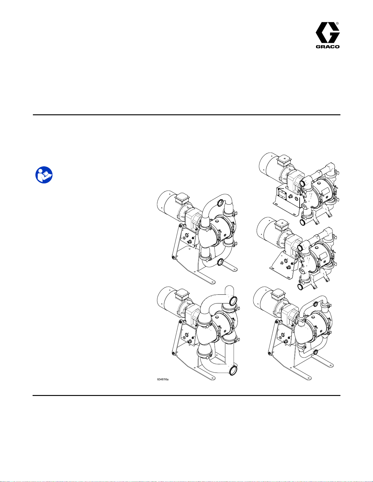
Graco SaniForce 2150, SaniForce 3000, SaniForce 4000 Repair Manual
Repair/Parts
SaniForce®
SaniForce® SaniForce®
Electric
Electric Electric
Inch,
2 22- --Inch, Inch,
Not
Not Not
stated.
stated. stated.
Formaximumworkingpressure,see
TechnicalSpecicationsheets.
Seepage10forapprovals.
3 33- --Inch, Inch,
approved
approved approved
See
See See
Important
Important Important
Readallwarningsandinstructionsinthismanualandinyour
Operationmanualbeforeusingtheequipment.Save Save
instructions.
instructions. instructions.
Operated
- --Operated Operated
Inch,
and
and and
for
for for
Approvals
Approvals Approvals
Safety
Safety Safety
2150,
2150, 2150,
Inch
4 44- --Inch Inch
use
use use
explosive
in ininexplosive explosive
page
page page
Instructions
Instructions Instructions
3000,
3000, 3000,
Diaphragm
Diaphragm Diaphragm
pumps
pumps pumps
with
electric
with with
electric electric
atmospheres
atmospheres atmospheres
for
more
for for
information.
more more
information. information.
4000,
4000, 4000,
Pump
Pump Pump
drive
for
uid
drive drive
for for
or
hazardous
or or
hazardous hazardous
For
For For
Save
transfer
uid uid
transfer transfer
professional
professional professional
these
these these
applications.
applications. applications.
(classied)
(classied) (classied)
use
use use
locations
locations locations
only.
only. only.
3A5133L
EN
unless
unless unless
otherwise
otherwise otherwise
PROVENQUALITY.LEADINGTECHNOLOGY.
Contents
Contents Contents
RelatedManuals................................................2
Warnings...........................................................3
CongurationNumberMatrixfor2150FG
Pumps..................................................6
CongurationNumberMatrixfor2150,3000,
and4000HSPumps.............................8
Approvals...........................................................10
OrderingInformation...........................................11
Troubleshooting..................................................12
Related
Related Related
ManualNumberTitle
3A5132
Manuals
Manuals Manuals
SaniForce™2150,3000,4000,Electric-OperatedDiaphragmPump,Operation
Repair................................................................14
PressureReliefProcedure............................14
CheckValveRepair.....................................14
StandardDiaphragmRepair.........................17
OvermoldedDiaphragmRepair.....................19
CenterSectionRepair..................................21
InstallCompressorKits.................................26
ReplacetheCompressor..............................27
Parts..................................................................28
KitsandAccessories....................................38
TechnicalSpecications......................................39
2
3A5133L
Warnings
Warnings Warnings
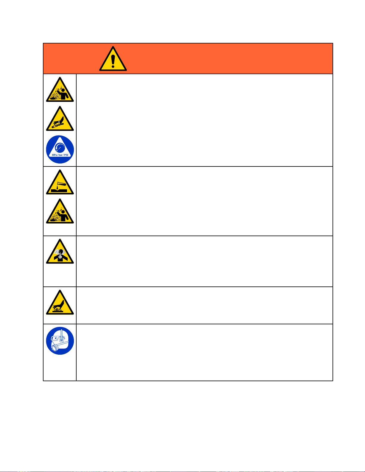
Thefollowingwarningsareforthesetup,use,grounding,maintenance,andrepairofthisequipment.The
exclamationpointsymbolalertsyoutoageneralwarningandthehazardsymbolsrefertoprocedure-specic
risks.Whenthesesymbolsappearinthebodyofthismanualoronwarninglabels,referbacktothese
Warnings.Product-specichazardsymbolsandwarningsnotcoveredinthissectionmayappearthroughout
thebodyofthismanualwhereapplicable.
DANGER
SEVERE
SEVERE SEVERE
Thisequipmentcanbepoweredbymorethan240V.Contactwiththisvoltagewill
causedeathorseriousinjury.
•Turnoffanddisconnectpoweratmainswitchbeforedisconnectinganycablesand
beforeservicingequipment.
•Thisequipmentmustbegrounded.Connectonlytogroundedpowersource.
•Allelectricalwiringmustbedonebyaqualiedelectricianandcomplywithalllocal
codesandregulations.
ELECTRIC
ELECTRIC ELECTRIC
SHOCK
SHOCK SHOCK
HAZARD
HAZARD HAZARD
Warnings
WARNING
FIRE
AND
FIRE FIRE
Flammablefumes,suchassolvent,inwork work
theequipmentcancausestaticsparking.Tohelppreventreandexplosion:
•Useequipmentonlyinwellventilatedarea.
•Eliminateallignitionsources;suchaspilotlights,cigarettes,portableelectriclamps,and
plasticdropcloths(potentialstaticsparking).
•Groundallequipmentintheworkarea.SeeGrounding Grounding
•Keepworkareafreeofdebris,includingsolvent,ragsandgasoline.
•Donotplugorunplugpowercords,orturnpowerorlightswitchesonoroffwhenammable
fumesarepresent.
•Useonlygroundedlines.
Stop
•Stop Stop
equipmentuntilyouidentifyandcorrecttheproblem.
•Keepaworkingreextinguisherintheworkarea.
Staticchargemaybuilduponplasticpartsduringcleaningandcoulddischargeandignite
ammablevapors.Tohelppreventreandexplosion:
•Cleanplasticpartsonlyinwellventilatedarea.
•Donotcleanwithadrycloth.
EXPLOSION
AND AND
EXPLOSION EXPLOSION
operation
operation operation
immediately
immediately immediately
HAZARD
HAZARD HAZARD
work
area
area area
canigniteorexplode.Solventowingthrough
Grounding
ifstaticsparkingoccursoryoufeelashock. ..Donotuse
instructions.
3A5133L3
Warnings
WARNING
PRESSURIZED
PRESSURIZED PRESSURIZED
Fluidfromtheequipment,leaks,orrupturedcomponentscansplashintheeyesoronskin
andcauseseriousinjury.
EQUIPMENT
EQUIPMENT EQUIPMENT
HAZARD
HAZARD HAZARD
•FollowthePressure Pressure
cleaning,checking,orservicingequipment.
•Tightenalluidconnectionsbeforeoperatingtheequipment.
•Checkuidlines,tubes,andcouplingsdaily.Replacewornordamagedpartsimmediately.
EQUIPMENT
EQUIPMENT EQUIPMENT
Misusecancausedeathorseriousinjury.
•Donotoperatetheunitwhenfatiguedorundertheinuenceofdrugsoralcohol.
•Donotexceedthemaximumworkingpressureortemperatureratingofthelowestrated
systemcomponent.SeeTechnical Technical
•Useuidsandsolventsthatarecompatiblewithequipmentwettedparts.SeeTechnical Technical
Specications
Specications Specications
Forcompleteinformationaboutyourmaterial,requestSafetyDataSheet(SDS)from
distributororretailer.
•TurnoffallequipmentandfollowthePressure Pressure
•Checkequipmentdaily.Repairorreplacewornordamagedpartsimmediatelywithgenuine
manufacturer’sreplacementpartsonly.
•Donotalterormodifyequipment.Alterationsormodicationsmayvoidagencyapprovals
andcreatesafetyhazards.
•Makesureallequipmentisratedandapprovedfortheenvironmentinwhichyouareusingit.
•Useequipmentonlyforitsintendedpurpose.Callyourdistributorforinformation.
•Routeuidlinesandcablesawayfromtrafcareas,sharpedges,movingparts,andhot
surfaces.
•Donotkinkoroverbenduidlinesoruseuidlinestopullequipment.
•Keepchildrenandanimalsawayfromworkarea.
•Complywithallapplicablesafetyregulations.
PRESSURIZED
PRESSURIZED PRESSURIZED
Pressure
MISUSE
MISUSE MISUSE
Relief
Procedure
Relief Relief
Procedure Procedure
HAZARD
HAZARD HAZARD
Technical
inallequipmentmanuals.Readuidandsolventmanufacturer’swarnings.
ALUMINUM
ALUMINUM ALUMINUM
PARTS
PARTS PARTS
whenyoustopspraying/dispensingandbefore
Specications
Specications Specications
Pressure
HAZARD
HAZARD HAZARD
Relief
Relief Relief
inallequipmentmanuals.
Procedure
Procedure Procedure
whenequipmentisnotinuse.
Technical
Useofuidsthatareincompatiblewithaluminuminpressurizedequipmentcancauseserious
chemicalreactionandequipmentrupture.Failuretofollowthiswarningcanresultindeath,
seriousinjury,orpropertydamage.
•Donotuse1,1,1-trichloroethane,methylenechloride,otherhalogenatedhydrocarbon
solventsoruidscontainingsuchsolvents.
•Donotusechlorinebleach.
•Manyotheruidsmaycontainchemicalsthatcanreactwithaluminum.Contactyourmaterial
supplierforcompatibility.
4
3A5133L
WARNING
THERMAL
THERMAL THERMAL
Fluidssubjectedtoheatinconnedspaces,includinglines,cancreatearapidriseinpressure
duetothethermalexpansion.Over-pressurizationcanresultinequipmentruptureandserious
injury.
•Openavalvetorelievetheuidexpansionduringheating.
•Replacelinesproactivelyatregularintervalsbasedonyouroperatingconditions.
EXPANSION
EXPANSION EXPANSION
HAZARD
HAZARD HAZARD
Warnings
PLASTIC
PLASTIC PLASTIC
Manysolventscandegradeplasticpartsandcausethemtofail,whichcouldcauseserious
injuryorpropertydamage.
•Useonlycompatiblesolventstocleanplasticstructuralorpressure-containingparts.
•SeeTechnical Technical
thesolventmanufacturerforinformationandrecommendationsaboutcompatibility.
•SeeTechnical Technical
andsolventmanufacturer’sSafetyDataSheet(SDS)andrecommendations.
TOXIC
TOXIC TOXIC
Toxicuidsorfumescancauseseriousinjuryordeathifsplashedintheeyesoronskin,
inhaled,orswallowed.
•ReadSafetyDataSheet(SDS)toknowthespecichazardsoftheuidsyouareusing.
•Storehazardousuidinapprovedcontainers,anddisposeofitaccordingtoapplicable
guidelines.
BURN
BURN BURN
Equipmentsurfacesanduidthat’sheatedcanbecomeveryhotduringoperation.Toavoid
severeburns:
•Donottouchhotuidorequipment.
PERSONAL
PERSONAL PERSONAL
Wearappropriateprotectiveequipmentwhenintheworkareatohelppreventseriousinjury,
includingeyeinjury,hearingloss,inhalationoftoxicfumes,andburns.Thisprotective
equipmentincludesbutisnotlimitedto:
PARTS
PARTS PARTS
Technical
Technical
FLUID
FLUID FLUID
HAZARD
HAZARD HAZARD
CLEANING
CLEANING CLEANING
Specications
Specications Specications
Specications
Specications Specications
OR
FUMES
OR OR
FUMES FUMES
PROTECTIVE
PROTECTIVE PROTECTIVE
SOLVENT
SOLVENT SOLVENT
inallequipmentmanualsformaterialsofconstruction.Consult
inthisandallotherequipmentinstructionmanuals.Readuid
HAZARD
HAZARD HAZARD
EQUIPMENT
EQUIPMENT EQUIPMENT
HAZARD
HAZARD HAZARD
•Protectiveeyewear,andhearingprotection.
•Respirators,protectiveclothing,andglovesasrecommendedbytheuidandsolvent
manufacturer.
3A5133L5
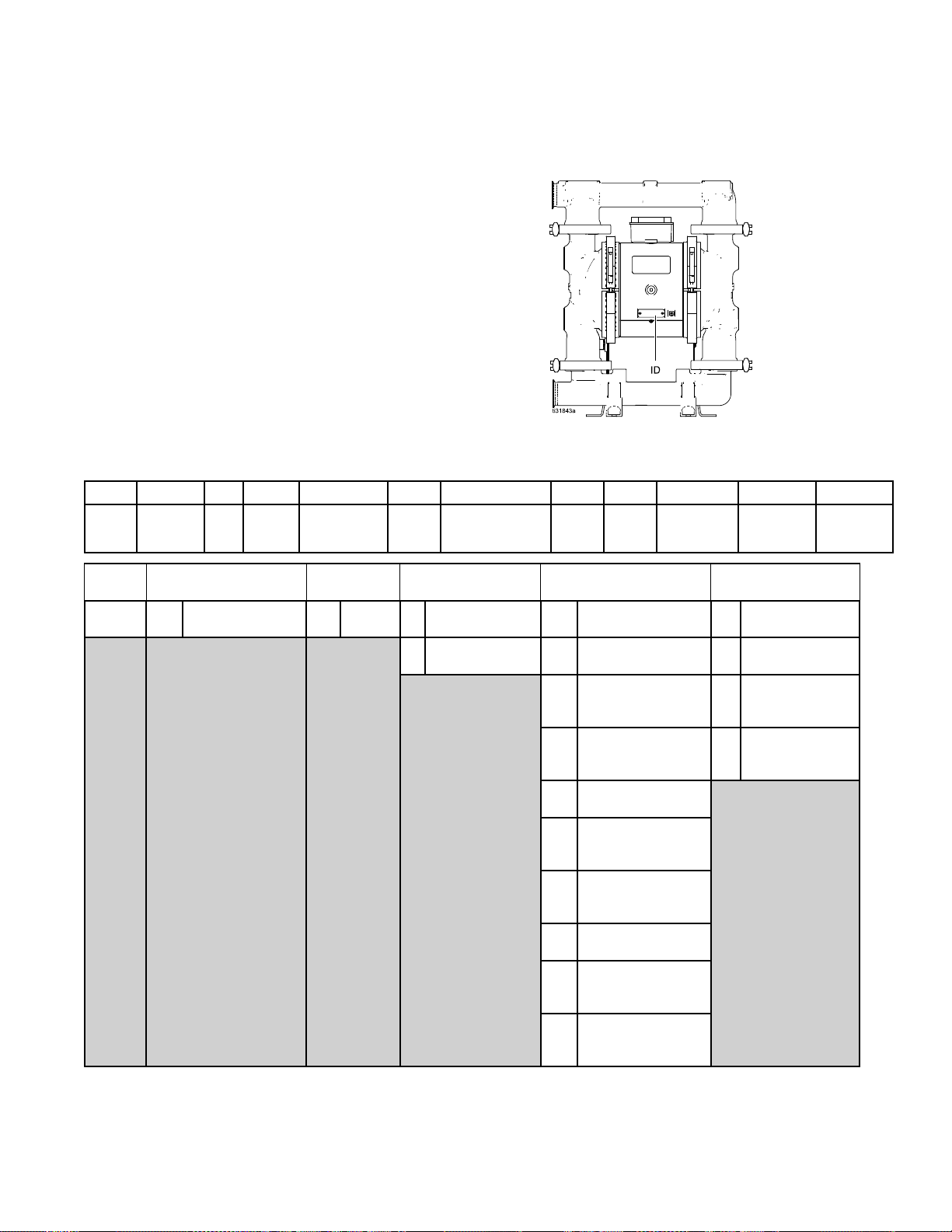
CongurationNumberMatrixfor2150FGPumps
Conguration
Conguration Conguration
Checktheidenticationplate(ID)forthe
CongurationNumberofyourpump.Usethe
followingmatrixtodenethecomponentsofyour
pump.
Whenyoureceiveyourpump,recordthe9character
partnumberfoundontheshippingbox(e.g.,
SP1B.0014):
_____________
AlsorecordthecongurationnumberonthepumpID
platetoassistyouwhenorderingreplacementparts:
_____________________________________
Sample
Sample Sample
2150
2150 2150
Pump
Model
Pump
Pump Pump
2150
2150 2150
Conguration
Conguration Conguration
FG
FG FG
Wetted
Section
Wetted
Wetted Wetted
FG
FG FG
E
E E
Drive
Section
Section Section
FoodGrade
Number
Number Number
Number:
Number: Number:
A
A A
Center
Section
2150FG
2150FG 2150FG
04
04 04
Gear
Boxand
Compressor
Drive
Drive Drive
E
E E
EA04AS13SSPTPTPT21
- --EA04AS13SSPTPTPT21 EA04AS13SSPTPTPT21
A
A A
Motor
Type
Type Type
Electric
Matrix
Matrix Matrix
Center
Center Center
Material
Material Material
Aluminum
A
A A
StainlessSteel
S
S S
S13
S13 S13
FluidCoversand
Manifolds
Section
Section Section
for
2150
for for
2150 2150
SS
SS SS
Seats
Gearbox
Gearbox Gearbox
Compressor
Compressor Compressor
94
94 94
04
04 04
05
05 05
06
06 06
14
14 14
15
15 15
16
16 16
24
24 24
25
25 25
26
26 26
FG
FG FG
PT
PT PT
Balls
orChecks
and
and and
NoGearboxor
Compressor
HighSpeedGear
Ratio
HighSpeed
GearRatio/120V
Compressor
HighSpeed
GearRatio/240V
Compressor
MidSpeedGear
Ratio
MidSpeed
GearRatio/120V
Compressor
MidSpeed
GearRatio/240V
Compressor
LowSpeedGear
Ratio
LowSpeed
GearRatio/120V
Compressor
LowSpeed
GearRatio/240V
Compressor
Pumps
Pumps Pumps
PT
PT PT
Diaphragms
PT
PT PT
Manifold
Seals
Motor
Motor Motor
Standard
A
A A
InductionMotor
ATEXInduction
C
C C
Motor
Flameproof
D
D D
InductionMotor
NoMotor
G
G G
21
21 21
Certication
63A5133L

CongurationNumberMatrixfor2150FGPumps
Fluid
Covers
Fluid Fluid
Covers Covers
Manifolds
Manifolds Manifolds
S13
S13 S13
S14
S14 S14
Stainless
steel,
TriClamp
Stainless
steel,DIN
and
Seat
and and
Material
Seat Seat
Material Material
316
SS
SS SS
Stainless
Steel
Ball
or
Ball Ball
Material
Material Material
CW
CW CW
PT
PT PT
SP
SP SP
Check
or or
Check Check
Polychloroprene
Weighted
PTFE
Santoprene
Diaphragm
Diaphragm Diaphragm
PT
PT PT
SP
SP SP
Material
Material Material
PTFE/EPDM
2-Piece
Santoprene/EPDM
2–Piece
Manifold
Manifold Manifold
Seals
Seals Seals
EPDMblank
EP
EP EP
PTFE
PT
PT PT
Certication
Certication Certication
nocertication
EN10204type
21
21 21
31
31 31
2.1
EN10204type
3.1
3A5133L
7
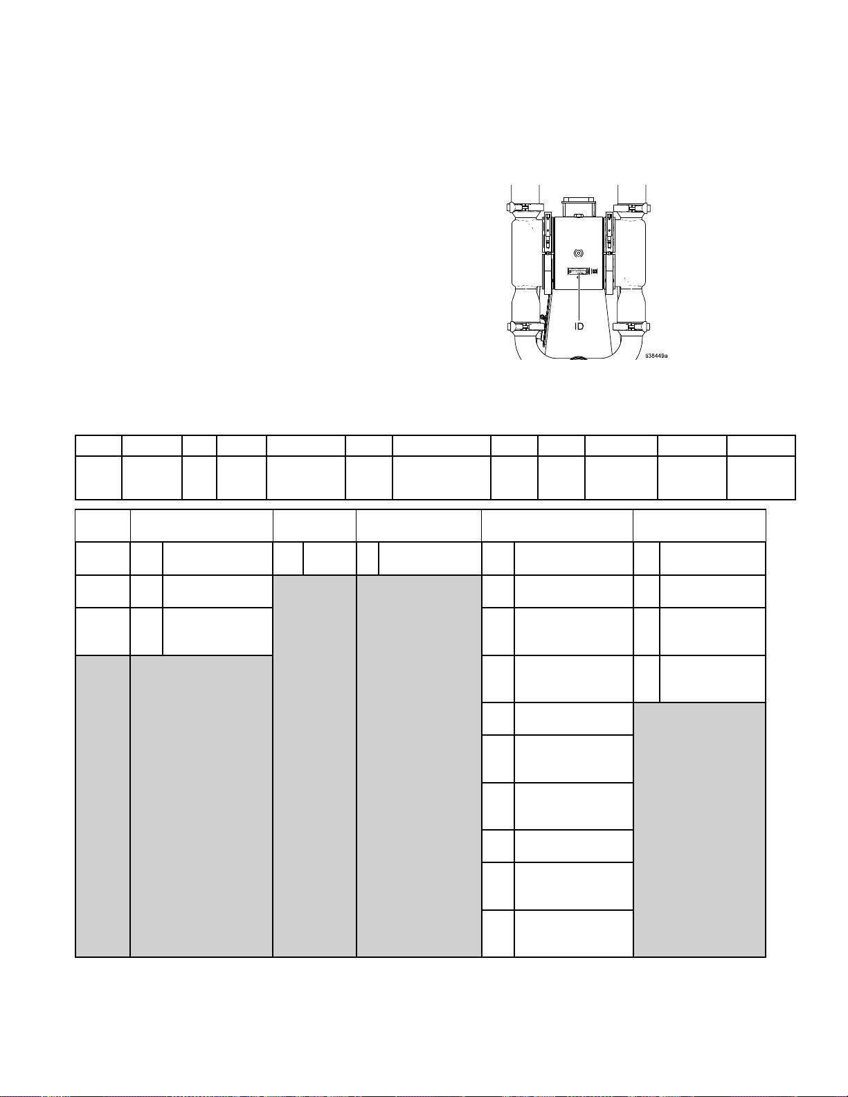
CongurationNumberMatrixfor2150,3000,and4000HSPumps
Conguration
Conguration Conguration
HS
HS HS
Sample
Sample Sample
2150
2150 2150
Pump
Model
Pumps
Pumps Pumps
Checktheidenticationplate(ID)forthe
CongurationNumberofyourpump.Usethe
followingmatrixtodenethecomponentsofyour
pump.
Whenyoureceiveyourpump,recordthe9character
partnumberfoundontheshippingbox(e.g.,
SP1B.0014):
_____________
AlsorecordthecongurationnumberonthepumpID
platetoassistyouwhenorderingreplacementparts:
_____________________________________
Conguration
Conguration Conguration
HS
HS HS
Wetted
Section
E
E E
Drive
Number
Number Number
Number:
Number: Number:
S
S S
Center
Section
2150HS
2150HS 2150HS
04
04 04
Gear
Boxand
Compressor
ES04ASSASSPTPSEP21
- --ES04ASSASSPTPSEP21 ES04ASSASSPTPSEP21
A
A A
Motor
Matrix
Matrix Matrix
SSA
SSA SSA
FluidCoversand
Manifolds
for
2150,
for for
2150, 2150,
SS
SS SS
Seats
3000,
3000, 3000,
PT
PT PT
Balls
orChecks
PS
PS PS
Diaphragms
and
and and
4000
4000 4000
EP
EP EP
Manifold
Seals
21
21 21
Certication
Pump
Pump Pump
2150
2150 2150
3000
3000 3000
4000
4000 4000
Wetted
Wetted Wetted
HS
HS HS
3A
3A 3A
PH
PH PH
Section
Section Section
HighSanitation
3ACertied
Pharmaceutical
Drive
Type
Drive Drive
Type Type
Electric
E
E E
Center
Center Center
Material
Material Material
S
S S
StainlessSteel
Section
Section Section
Gearbox
Gearbox Gearbox
Compressor
Compressor Compressor
94
94 94
04
04 04
05
05 05
06
06 06
14
14 14
15
15 15
16
16 16
24
24 24
25
25 25
26
26 26
and
and and
NoGearboxor
Compressor
HighSpeedGear
Ratio
HighSpeed
GearRatio/120V
Compressor
HighSpeed
GearRatio/240V
Compressor
MidSpeedGear
Ratio
MidSpeed
GearRatio/120V
Compressor
MidSpeed
GearRatio/240V
Compressor
LowSpeedGear
Ratio
LowSpeed
GearRatio/120V
Compressor
LowSpeed
GearRatio/240V
Compressor
Motor
Motor Motor
Standard
A
A A
InductionMotor
ATEXInduction
C
C C
Motor
Flameproof
D
D D
InductionMotor
NoMotor
G
G G
83A5133L
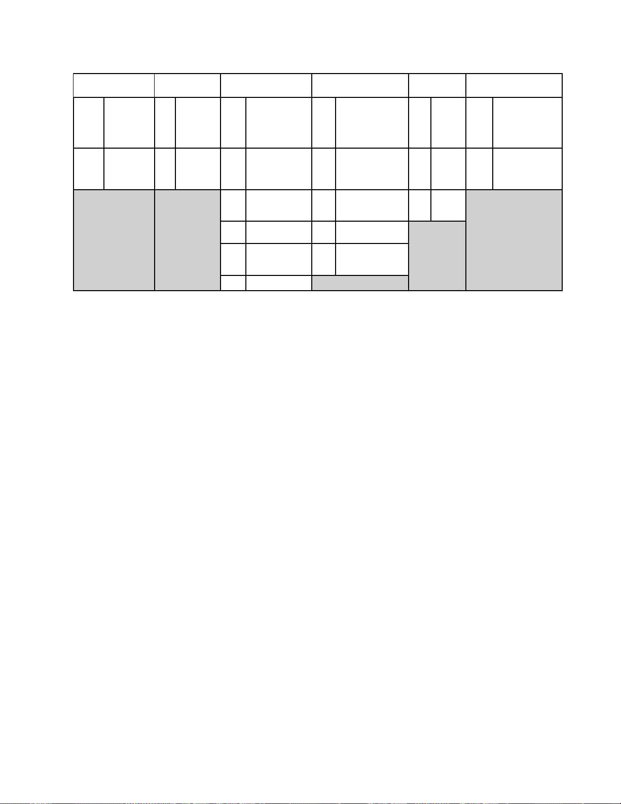
CongurationNumberMatrixfor2150,3000,and4000HSPumps
Fluid
Covers
Fluid Fluid
Covers Covers
Manifolds
Manifolds Manifolds
SSA
SSA SSA
SSB
SSB SSB
Stainless
Steel,
Tri-Clamp
(HS/3-A/
PH)
Stainless
Steel,DIN
(HS/3A/PH)
and
Seat
and and
Material
Seat Seat
Material Material
316
FL
FL FL
Stainless
Steel
Flapper
316
SS
SS SS
Stainless
Steel
Ball
or
or or
Flapper,check,
StainlessSteel
Buna-N
Polychloroprene
Weighted
FKMFluoroelastomer
PTFE
Santoprene
Check
Check Check
Ball Ball
Material
Material Material
—
— —
BN
BN BN
CW
CW CW
FK
FK FK
PT
PT PT
SP
SP SP
Diaphragm
Diaphragm Diaphragm
BN
BN BN
EO
EO EO
FK
FK FK
PS
PS PS
SP
SP SP
Material
Material Material
Buna-N
EPDM
Overmolded
FKM
Fluoroelastomer
PTFE/Santoprene2-Piece
Santoprene/EPDM
2Piece
Manifold
Manifold Manifold
Seals
Seals Seals
Buna-N
BN
BN BN
EPDM
EP
EP EP
FKM
FK
FK FK
Certication
Certication Certication
EN10204type
21
21 21
31
31 31
2.1
EN10204type
3.1
3A5133L9
Approvals
Approvals
Approvals Approvals
Approvals
Approvals Approvals
✦PumpswithmotorcodeCareapprovedto:
✚PumpswithmotorcodeGareapprovedto:
★MotorscodedDareapprovedto:
DiaphragmmaterialscodedEO,PT,orPS
combinedwithcheckmaterialscodedFLor
PTcomplywith:
AllModels(exceptgearboxandcompressor
codes05,15,and25,ormotorcodeD)are
approvedto:
DiaphragmmaterialscodedEO,PTorPS
combinedwithcheckmaterialscodedFLor
PTcomplywith:
II2G
ExhdIIBT3Gb
II2G
ExhIIBT3Gb
ClassI,Div1,GroupD,T3B
ClassII,Div1,GroupF&G,T3B
EC1935/2004
ClassVI
AlluidcontactmaterialsareFDA-compliant
andmeettheUnitedStatesCodeofFederal
Regulations(CFR).
103A5133L

OrderingInformation
Ordering
Ordering Ordering
To
To To
Visitwww.graco.com
To
To To
Please
Please Please
OR
OR OR
UsetheOnline Online
To
To To
Please
Please Please
Information
Information Information
Find
Find Find
Specify
Specify Specify
Order
Order Order
Your
Your Your
call
your
call call
your your
Online
call
your
call call
your your
Nearest
Nearest Nearest
the
Conguration
the the
Conguration Conguration
distributor.
distributor. distributor.
Diaphragm
Diaphragm Diaphragm
Replacement
Replacement Replacement
distributor.
distributor. distributor.
Distributor
Distributor Distributor
of
New
of of
a aaNew New
Pump
Selector
Pump Pump
Selector Selector
Parts
Parts Parts
Tool
Tool Tool
at atatwww.graco.com www.graco.com
Pump
Pump Pump
www.graco.com
. ..SearchforSelector Selector
Selector
.
3A5133L
11
Troubleshooting
Troubleshooting
Troubleshooting Troubleshooting
•FollowthePressureReliefProcedure,page14,
beforecheckingorservicingtheequipment.
Problem
Problem Problem
Pumpcyclesbutwillnot
primeand/orpump.
Thecentersectionis
excessivelyhot.
Pumpfailstoholduid
pressureatstall.
NOTE:
NOTE: NOTE:
arenot100%uidtight.
Flapperchecks
Cause
Cause Cause
Pumpisrunningtoofast,causing
cavitationbeforeprime.
Centersectionhasnoairpressure,
orairpressureistoolow.
Checkvalveballisseverelywornor
wedgedinseatormanifold.
Thepumphasinsufcientsuction
pressure.
Seatisseverelyworn.
Outletorinletisrestricted.
Inletttingsormanifoldsareloose.
Manifoldo-ringsaredamaged.
Thedriveshaftisbroken.
Checkvalveballs,seats,oro-rings
areworn.
Manifoldscrewsoruidcover
screwsareloose.
•Checkallpossibleproblemsandcausesbefore
disassembly.
Solution
Solution Solution
Slowdownthecontroller(VFD)
Applyairpressuretocentersection
peryourapplicationrequirements.
Replacetheballandseat.
Increasethesuctionpressure.See
theOperationmanual.
Replacetheballandseat.
Removetherestriction.
Tighten.
Replaceo-rings.
Replace.
Replace.
Tighten.
Themotorisoperating,
butthepumpwillnot
cycle.
Pumpowrateiserratic.
Pumpmakesunusual
noises.
12
Diaphragmshaftboltisloose.
Flapvalvesinstalledupside-down.
Motororcontrolleriswired
improperly.
Theleakdetector(ifinstalled)has
tripped.
Thejawcouplingbetweenthe
motorandgearboxisnotconnected
properly.
Suctionlineisclogged.
Checksarestickyorleaking.Cleanorreplace.
Diaphragm(orbackup)ruptured.
Pumpisoperatingnearoratstall
pressure.
Tighten.
Installtheappervalvewiththetext
sidefacingtheseat.
Wirepermanual. Pumpwillnotcycle.
Checkdiaphragmforruptureor
incorrectinstallation.Repairor
replace.
Checktheconnection.
Inspect;clear.
Replace.
Adjustairpressureorslowthepump
speed.
3A5133L
Troubleshooting
Problem
Problem Problem
Airconsumptionishigher
thanexpected.
Airbubblesinuid.
Pumpleaksuid
externallyfromjoints.
Thecontrollerfaultsor
shutsdown.
Cause
Cause Cause
Attingisloose.
Looseordamagedo-ringsorshaft
seal.
Diaphragm(orbackup)ruptured.
Suctionlineisloose.
Diaphragm(orbackup)ruptured.
Loosemanifolds,damagedseatsor
o-rings.
Loosediaphragmshaftbolt.
Loosemanifoldscrewsoruidcover
screws.
Manifoldo-ringswornout.
AGFCIhastripped.Removethecontrollerfromthe
Supplypowerispoor.Determineandxthesourceofthe
Operationalparametersare
exceeded.
Solution
Solution Solution
Tighten.Inspectthreadsealant.
Replace.
Replace.
Tighten.
Replace.
Tightenmanifoldboltsorreplace
seatsoro-rings.
Tighten.
Tighten.
Replaceo-rings.
GFCIcircuit.
powerproblem.
Seeperformancechart;ensure
pumpisoperatingwithinthe
continuousdutyrange.
regenerationfaultfrom
VFD
NOTE:
NOTE: NOTE:
ForproblemswithaVariableFrequencyDevice(VFD),seeyourVFDmanual.
Inletcheckclogged/improperly
installed
BrokendiaphragmboltReplacebolt
Removedebris/installproperly Excessivemotor
3A5133L13
Repair
Repair
Repair Repair
NOTE:
NOTE: NOTE:
looselyassembleinitiallytoensureacceptable
alignment.Onceallcomponentsareinplace,tighten
allclamps.
Pressure
Pressure Pressure
1.Turnoffthepumpanddisconnectpowertothe
2.Closethemasterairvalve(J)toshutofftheair
3.Opentheuiddrainvalve(L)torelieveuid
4.Closethepumpairinletport(E)onthepneumatic
Whenreassemblinguidsectioncomponents,
Relief
Relief Relief
FollowthePressureReliefProcedure
wheneveryouseethissymbol.
Thisequipmentstayspressurizeduntilpressureis
manuallyrelieved.Tohelppreventseriousinjury
frompressurizeduid,suchassplashinguid,
followthePressureReliefProcedurewhenyou
stopdispensingandbeforecleaning,checking,or
servicingtheequipment.
system.
tothepump.
pressure.Haveacontainerreadytocatchthe
drainage.
enclosure.
Procedure
Procedure Procedure
Disassemble
Disassemble Disassemble
1.FollowthePressureReliefProcedure,page14.
Disconnectpowerfromthemotor.Disconnectall
uidandairlines.
2.Removetheclamps(31)holdingtheoutlet
manifold(3)totheuidcovers(2),thenremove
theoutletmanifold.
3.Removetheballcheckvalveassemblies:
a.Onthe2150FG,removetheseats(6),balls
(7),ando-rings(8).
b.Onthe2150HS,removetheballstops(28),
balls(7),andgaskets(8a).
4.Repeatfortheinletmanifold.
5.Tocontinuewithdiaphragmdisassembly,see
DisassembletheStandardDiaphragms,page17.
Reassemble
Reassemble Reassemble
1.Cleanallpartsandinspectforwearordamage.
Replacepartsasneeded.
2.Reassembleinthereverseorder,followingall
notesintheillustration.Puttheinletmanifoldon
rst.Besuretheballchecksandmanifoldsare
assembledexactly exactly
uidcovers(2),thearrows(A)must must
theoutletmanifold(3).Foruidcoverswithout
arrows,thetallestopeningintheuidcovermust must
beattachedtotheoutletmanifold.
the
Ball
the the
the
the the
exactly
Check
Ball Ball
Check Check
Ball
Check
Ball Ball
Check Check
asshown.Ifpresentonthe
Valve
Valve Valve
Valve
Valve Valve
must
pointtoward
must
Check
Check Check
Tools
Tools Tools
•O-ringpick
NOTE:
NOTE: NOTE:
andseatsinarangeofmaterials.O-ringkitsalso
areavailable.
NOTE:
NOTE: NOTE:
alwaysreplacetheseatswhenreplacingtheballs.
Also,replacetheo-ringseverytimethemanifoldis
removed.
14
Valve
Valve Valve
Required
Required Required
Kitsareavailablefornewcheckvalveballs
Toensureproperseatingofthecheckballs,
Repair
Repair Repair
3A5133L
 Loading...