

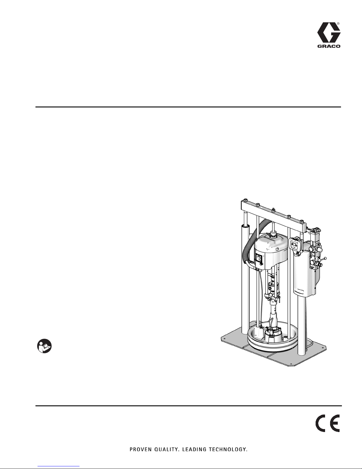
Graco D200, L20c, S20, D60, D200S Repair Manual
Repair - Parts
313527ZAD
Supply Systems
For transferring or dispensing sealants, adhesives, or other medium to high viscosity
fluids. For professional use only.
Not approved for use in European explosive atmosphere locations.
L20c 2 inch single post elevator
20 liter (5 gallon) size
100 psi (0.7 MPa, 7 bar) Maximum Air Inlet Pressure
S20 3 inch single post
20 liter (5 gallon) size
125 psi (0.9 MPa, 9 bar) Maximum Air Inlet Pressure
EN
D60 3 inch dual post
60 liter (16 gallon) size
150 psi (1.0 MPa, 10 bar) Maximum Air Inlet Pressure
D200 3 inch dual post
200 liter (55 gallon), 115 liter (30 gallon),
60 liter (16 gallon) size, 30 liter (8 gallon),
20 liter (5 gallon) sizes
150 psi (1.0 MPa, 10 bar) Maximum Air Inlet Pressure
D200S 6.5 inch dual post
200 liter (55 gallon), 115 liter (30 gallon)
125 psi (0.9 MPa, 9 bar) Maximum Air Inlet Pressure
Important Safety Instructions
Read all warnings and instructions in this manual.
Save these instructions.
See page 6 for model information and approvals.
The Graco Control Architecture Electric Components
are Listed in Intertek’s Directory of Listed Products.
D200
CM14BA
Ti10429A

Table of Contents
Related Manuals ...........................3
Warnings .................................4
Models ...................................6
Component Identification ...................10
D200 3 in. and D200s 6.5 in. Dual Post ......10
S20 3 in. Single Post and D60 3 in. Dual Post . 11
Integrated Air Control Module .............. 12
Integrated Air Line Accessories ............ 12
2-Button Interlock Air Controls ............. 12
L20c 2in. Elevator ....................... 13
L20c 2 in. Air Controls ....................14
Platen Component Identification ............15
Before Beginning Repair ...................16
Grounding ............................. 16
Pressure Relief Procedure ................16
Flush Before Using Equipment .............17
Maintenance Procedures ...................17
Platen Maintenance ..................... 17
Adjust Spacers ......................... 17
Remove and Reinstall Wipers ..............18
Troubleshooting ........................... 22
Ram ................................. 22
Repair ...................................23
Disconnect Pump from Platen .............23
Connect Platen ......................... 24
Remove Wipers ......................... 24
Install Wipers ...........................24
Remove Displacement Pump ..............24
Install Displacement Pump ................26
Remove Air Motor .......................27
Install Air Motor .........................29
Supply Unit Repair ...................... 31
Power Supply ..........................36
Parts .................................... 38
D200s 6.5 in. Supply Units ................ 39
D200 3 in. Supply Units .................. 41
D200s and D200 Pump Mounts for 55 Gallon (200
Liter) Platen ........................43
D200s and D200 Pump Mounts for 5 Gallon (20
Liter), 8 Gallon (30 Liter), 16 Gallon (60 Liter),
and 30 Gallon (115 Liter) Platens ........44
D60 3 in. Dual Post Supply Unit ............ 46
D60 Pump Mounts 257623 and 257624 for 5 Gallon
(20 Liter), 8 Gallon (30 Liter), and 16 Gallon (60
Liter) Platens .......................48
S20 3 In. Single Post Ram ................ 49
S20 3 In. Single Post Ram Mounting Kit ......51
L20c 2 In. Elevator .......................52
Air Control Kit- L20c 2 In. Elevator ..........53
Power Supply - D200s, D200, D60, and S20 3 in.
Supply Unit .........................54
30 and 55 Gallon Platen ..................56
20 Liter (5 Gallon), 30 Liter (8 Gallon), and 60 Liter
(16 Gallon) Platens ...................58
Accessories ..............................62
D200s, D200, and D60 DataTrak Accessory Kits 62
Varied Parts for DataTrak Accessory Kits .....63
Two-Button Interlock Air Control Kit ..........64
Drum Roller Kits for D200 and D200S Supply Units,
255627 ............................64
Drum Position Clamp Set for D200 Supply Units,
206537 ............................64
Drum Position Clamp for D200S Supply Units . 64
Enclosed Wet Cup Recirc Kit ...............64
200 Liter (55 Gallon) Platen Cover Kits, 255691 64
Light Tower Kit, 255467 ...................64
Check-Mate Displacement Pump Kits ........64
Dura-Flo Displacement Pump Kits ..........64
S20 Hose Replacement Kit ................64
Dimensions ...............................65
Dimensions ............................66
Technical Data ............................67
Graco Standard Warranty ...................68
2 313527ZAD

Related Manuals
The following manuals are available at www.graco.com.
Component manuals in English:
Manual Description
313526 Supply Systems Operation
313528 Tandem Supply Systems Operation
313529 Tandem Supply Systems Repair-Parts
Related Manuals
312375
312376
311827
311825
311717
311828
311826
311833
312889
312467
312468
312469
312470
311238
312796
312374 Air Controls Instructions-Parts
312491 Pump Fluid Purge Kit
Check-Mate®Displacement Pumps
Instructions-Parts
Check-Mate®Pump Packages
Instruction-Parts
Dura-Flo™Displacement Pumps (145cc,
180cc, 220cc, 290cc) Instructions-Parts
Manual
Dura-Flo™Displacement Pumps (430cc,
580cc) Instructions-Parts Manual
Carbon Steel Displacement Pump (1000cc)
Instructions-Parts Manual
Dura-Flo™Pump Packages (145cc, 180cc,
220cc, 290cc) Instructions-Parts Manual
Dura-Flo™Pump Packages (430cc, 580cc)
Instructions-Parts Manual
Two-Ball NXT™Pump Packages (1000cc)
Instructions-Parts Manual
60 cc Check-Mate Displacement Pump
Repair Parts Manual
100 cc Check-Mate Displacement Pump
Repair Parts Manual
200 cc Check-Mate Displacement Pump
Repair Parts Manual
250 cc Check-Mate Displacement Pump
Repair Parts Manual
500 cc Check-Mate Displacement Pump
Repair Parts Manual
NXT™Air Motor (Nxxxxx models)
Instructions-Parts
NXT™Air Motor (Mxxxxx models)
Instructions-Parts
312492 Drum Roller Kit Instruction
312493 Light Tower Kit Instruction
406681 Platen Cover Kit
334048 EPDM Hose Wiper Kit
334644
313527ZAD 3
Xtreme®XL Air Motor, Instructions-Parts
Warnings
Warnings
SKIN INJECTION HAZARD
High-pressure fluid from gun, hose leaks, or ruptured components will pierce skin. This may look like just
a cut, but it is a serious injury that can result in amputation. Get immediate surgical treatment.
• Do not point gun at anyone or at any part of the body.
• Do not put your hand over the dispense outlet.
• Do not stop or deflect leaks with your hand, body, glove, or rag.
• Follow Pressure Relief Procedure in this manual, when you stop dispensing and before cleaning,
checking, or servicing equipment.
MOVING PARTS HAZARD
Moving parts can pinch or amputate fingers and other body parts.
• Keep clear of moving parts.
• Do not operate equipment with protective guards or covers removed.
• Pressurized equipment can start without warning. Before checking, moving, or servicing equipment,
follow the Pressure Relief Procedure in this manual. Disconnect power or air supply.
WARNING
FIRE AND EXPLOSION HAZARD
Flammable fumes, such as solvent and paint fumes, in work area can ignite or explode. To help prevent
a fire and explosion:
• Use equipment only in well ventilated area.
• Eliminate all ignition sources; such as pilot lights, cigarettes, portable electric lamps, and plastic drop
cloths (potential static arc).
• Keep work area free of debris, including solvent, rags and gasoline.
• Do not plug or unplug power cords, or turn power or light switches on or off when flammable fumes
are present.
• Ground all equipment in the work area. See Grounding instructions.
• Use only grounded hoses.
• Hold gun firmly to side of grounded pail when triggering into pail.
• If there is static sparking or you feel a shock, stop operation immediately. Do not use equipment
until you identify and correct the problem.
• Keep a working fire extinguisher in the work area.
EQUIPMENT MISUSE HAZARD
Misuse can cause death or serious injury.
• Do not operate the unit when fatigued or under the influence of drugs or alcohol.
• Do not exceed the maximum working pressure or temperature rating of the lowest rated system
component. See Technical Data in all equipment manuals.
• Do not leave the work area while equipment is energized or under pressure. Turn off all equipment
and follow the Pressure Relief Procedure in this manual when equipment is not in use.
• Check equipment daily. Repair or replace worn or damaged parts immediately with genuine manufacturer’s replacement parts only.
• Do not alter or modify equipment.
• Use equipment only for its intended purpose. Call your distributor for information.
• Route hoses and cables away from traffic areas, sharp edges, moving parts, and hot surfaces.
• Do not kink or over bend hoses or use hoses to pull equipment.
• Keep children and animals away from work area.
• Comply with all applicable safety regulations.
4 313527ZAD
Warnings
WARNING
ELECTRIC SHOCK HAZARD
This equipment must be grounded. Improper grounding, setup, or usage of the system can cause electric shock.
• Turn off and disconnect power cord before servicing equipment.
• Use only grounded electrical outlets.
• Use only 3-wire extension cords.
• Ensure ground prongs are intact on power and extension cords.
• Do not expose to rain. Store indoors.
SPLATTER HAZARD
Hot or toxic fluid can cause serious injury if splashed in the eyes or on skin. During blowoff of platen
splatter may occur.
• Use minimum air pressure when removing platen from drum.
TOXIC FLUID OR FUMES HAZARD
Toxic fluids or fumes can cause serious injury or death if splashed in the eyes or on skin, inhaled, or
swallowed.
• Read MSDS’s to know the specific hazards of the fluids you are using.
• Store hazardous fluid in approved containers, and dispose of it according to applicable guidelines.
• Always wear impervious gloves when spraying or cleaning equipment.
PERSONAL PROTECTIVE EQUIPMENT
You must wear appropriate protective equipment when operating, servicing, or when in the operating
area of the equipment to help protect you from serious injury, including eye injury, inhalation of toxic
fumes, burns, and hearing loss. This equipment includes but is not limited to:
• Protective eyewear
• Clothing and respirator as recommended by the fluid and solvent manufacturer
• Gloves
• Hearing protection
313527ZAD 5
Models
Models
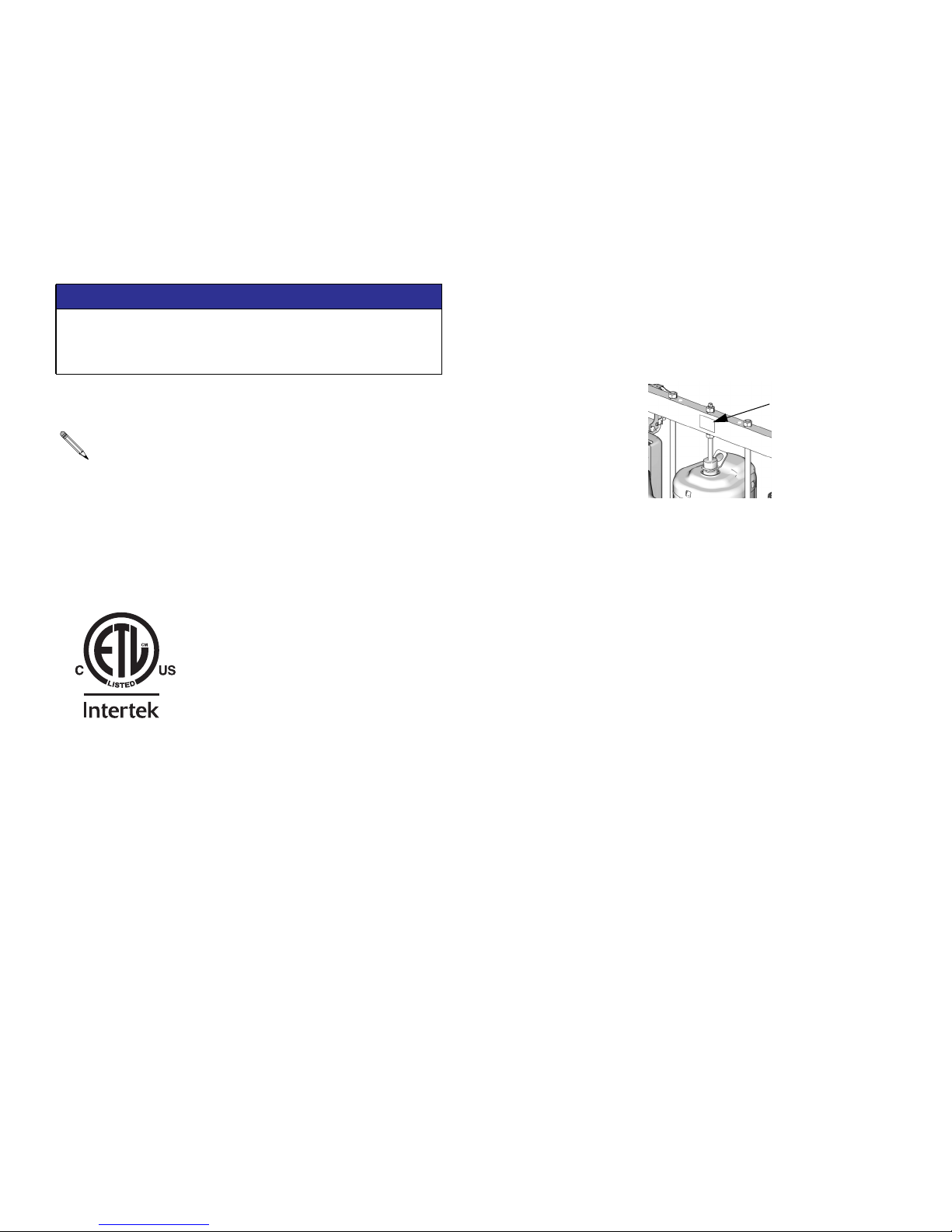
Check the identification plate (ID) for the 6-digit part number of the supply system. Use the following matrix to define
the construction of the supply system, based on the six digits. For example, Part No. CM14BA represents a
Check-Mate supply system (CM), a carbon steel Check-Mate 100 MaxLife
air motor with remote DataTrak (pump code 14), a 3 in. dual post ram with integrated air controls (B) and a 55-gallon,
uncoated platen with a neoprene seal (A).
NOTICE
To prevent damage to DataTrak soft key buttons, do
not press the buttons with sharp objects such as pens,
plastic cards, or fingernails.
Systems with the GD as the first and second digits are Dura-Flo supply systems.
Some configurations in the following matrix cannot be built. See the Product
Selection Guide for available systems
®
displacement pump with an NXT 2200
ID
ti11157a
To order replacement parts, see Parts section in manual 313527. The digits in the matrix on the next page do not
correspond to the Ref. Nos. in the Parts drawings and lists.
All supply systems with DataTrak and 24 VDC or 100-240 VAC power supplies are ETL approved.
6 313527ZAD

Models
CM 14 B
First and
Second Digit
CM
(Supply
System with
Check-Mate
displacement
pump)
GD
(Supply
System with
Dura-Flo
displacement
pump)
Third and
Fourth Digit Fifth Digit
Pump Code
(See Table 1
for 2-digit
Check-Mate
Pump Code)
(See Table 2
for 2-digit
Dura-Flo
Pump Code)
Size Style
1 2 in. L20c no volt
2 3 in. S20c no volt INT C
3 3 in. S20 no volt INT F
4 3 in. D60 no volt INT G
5 3 in. D200 no volt INT H
6 3 in D200i no volt
7 6.5 in. D200s no volt INT K
8 6.5 in. D200si no volt
9 3 in. D200 24 VDC INT M
A 3 in. D200i 24 VDC
B 3 in. D200
C 3 in. D200i
F 6.5 in. D200s 24 VDC INT U
G 6.5 in. D200si 24 VDC
H 6.5 in. D200s
J 6.5 in. D200si
L 3 in. S20
M 3 in. S20 24 VDC INT 9
R 3 in. D60
T 3 in. D60i
U 3 in. D60 24 VDC INT
W 3 in. D60i 24 VDC
Y 3 in. D60i no volt
Ram Options
DataTrak
Voltage Air Controls
100-240
VAC INT S
100-240
VAC
100-240
VAC INT Y
100-240
VAC
100-240
VAC INT 8
100-240
VAC INT A
100-240
VAC
Air Control
Panel B
2-Button
Interlock J
2-Button
Interlock L
2-Button
Interlock R
2-Button
Interlock T
2-Button
Interlock W
2-Button
Interlock 7
2-Button
Interlock D
2-Button
Interlock
2-Button
Interlock
A
Sixth Digit
Platen and Seal Options
Platen
Size
20 L
(5 Gal) F, SW CS Nitrile
20 L
(5 Gal) F, SW CS
20 L
(5 Gal) F, SW SST
20 L
(5 Gal) F, DW CS Nitrile
20 L
(5 Gal) F, DW CS
30 L
(8 Gal) F, SW CS Nitrile
30 L
(8 Gal) F, SW CS
30 L
(8 Gal) F, SW SST
30 L
(8 Gal) F, DW CS Nitrile
30 L
(8 Gal) F, DW CS
60 L
(16 Gal) F, SW CS Nitrile
60 L
(16 Gal) F, SW CS
60 L
(16 Gal) F, SW SST
60 L
(16 Gal) F, DW CS Nitrile
60 L
(16 Gal) F, DW CS
115 L
30 Gal D CS EPDM
200 L
(55 Gal) DR
200 L
(55 Gal) DR AL EPDM
200 L
(55 Gal) DR AL Neoprene
200 L
(55 Gal) DR AL EPDM Hose
Platen
Style
Platen
Material
PTFE
coated
AL EPDM
Seal
Material
Polyure-
thane
PTFE
coated
Polyure-
thane
Polyure-
thane
PTFE
coated
Polyure-
thane
Polyure-
thane
PTFE
coated
Polyure-
thane
KEY:
S = Single post ram i = 2-Button Interlock F = Flat SW = Single wiper
c = Cart mounted s = 6.5 inch D = D Style DW = Double wiper
D = Dual post ram INT = Integrated air controls DR = Dual o-ring
* Other Available Models: 262868. This model is the same as CM-_ _-3-B models, such as CM-11-3-B, but uses Check-Mate
Pump P40DCS (NXT2200/CM 100) instead of the other pumps listed on page 8.
313527ZAD 7

Models
Table 1: Check-Mate Pump Code/Part No. Index
Pump Part No.
Pump
Code
(see manual
312376)
NXT 200/CM 60
4A P05LCS
4B P05LCM
4C P05LSS
4F P05LSM
NXT 400/CM 60
6A P11LCS
6B P11LCM
6C P11LSS
6F P11LSM
6G P11RCS
6H P11RCM
6J P11RSS
6K P11RSM
61 P11SCS
62 P11SCM
63 P11SSS
64 P11SSM
NXT 700/CM 60
7A P20LCS
7B P20LCM
7C P20LSS
7F P20LSM
7G P20RCS
7H P20RCM
7J P20RSS
7K P20RSM
71 P20SCS
72 P20SCM
73 P20SSS
74 P20SSM
NXT 1200/CM 60
8A P38LCS
8B P38LCM
8C P38LSS
8F P38LSM
8G P38RCS
8H P38RCM
8J P38RSS
8K P38RSM
Pump Part No.
Pump
Code
(see manual
312376)
81 P38SCS
82 P38SCM
83 P38SSS
84 P38SSM
NXT 1800/CM 60
9A P61LCS
9B P61LCM
9C P61LSS
9F P61LSM
9G P61RCS
9H P61RCM
9J P61RSS
9K P61RSM
91 P61SCS
92 P61SCM
93 P61SSS
94 P61SSM
NXT 2200/CM 100
11 P40LCS
12 P40LCM
1F P40LSS
1G P40LSM
13 P40RCS
14 P40RCM
1H P40RSS
1J P40RSM
10 P40SSS
1A P40SSM
19 P40SCS
NXT 3400/CM 100
15 P63LCS
16 P63LCM
1T P63LSS
1U P63LSM
17 P63RCS
18 P63RCM
1W P63RSS
1Y P63RSM
1B P63SSS
1C P63SSM
Pump Part No.
Pump
Code
(see manual
312376)
NXT 2200/CM 200
21 P23LCS
22 P23LCM
23 P23RCS
24 P23RCM
25 P23LSS
26 P23LSM
27 P23RSS
28 P23RSM
NXT 3400/CM 200
29 P36LCS
2A P36LCM
2B P36RCS
2C P36RCM
2F P36LSS
2G P36LSM
2H P36RSS
2J P36RSM
NXT 6500/CM 200
2L P68LCS
2M P68LCM
2R P68RCS
2S P68RCM
2T P68LSS
2U P68LSM
2W P68RSS
2Y P68RSM
20 P68SCS
NXT 3400/CM 250
31 P29LCS
32 P29LCM
33 P29RCS
34 P29RCM
35 P29LSS
36 P29LSM
37 P29RSS
38 P29RSM
Pump Part No.
Pump
Code
(see manual
312376)
NXT 6500/CM 250
39 P55LCS
3A P55LCM
3B P55RCS
3C P55RCM
3F P55LSS
3G P55LSM
3H P55RSS
3J P55RSM
Xtreme XL/CM 250
3L P85LCS
3M P85LCM
3R P85LSS
3S P85LSM
NXT 3400/CM 500
51 P14LCS
52 P14LCM
53 P14RCS
54 P14RCM
55 P14LSS
56 P14LSM
57 P14RSS
58 P14RSM
NXT 6500/CM 500
59 P26LCS
5A P26LCM
5B P26RCS
5C P26RCM
5F P26LSS
5G P26LSM
5H P26RSS
5J P26RSM
Xtreme XL/CM 500
5L P42LCS
5M P42LCM
5R P42LSS
5S P42LSM
No Pump
NN
See manual 312375 or the ID plate on the pump to determine pump identification code.
8 313527ZAD

Table 2: Dura-Flo Pump Identification Code/Part No. Index
Models
Pump Part No.
Pump
Code
(see manual
311828)
NXT 2200/DF 145SS
A1 P31LSS
A2 P31LSM
A3 P31HSS
A4 P31HSM
NXT 3400/DF 145SS
B1 P46LSS
B2 P46LSM
B3 P46HSS
B4 P46HSM
NXT 3400/DF 180SS
B5 P41LSS
B6 P41LSM
B7 P41HSS
B8 P41HSM
NXT 3400/DF 220SS
C1 P30LSS
C2 P30LSM
C3 P30HSS
C4 P30HSM
NXT 6500/DF 220SS
CA P57LSS
CB P57LSM
CC P57HSS
CD P57HSM
NXT 6500/DF 290SS
D1 P45LSS
D2 P45LSM
D3 P45HSS
D4 P45HSM
Xtreme XL/DF 290SS
DL P71LSS
DM P71LSM
DR P71HSS
DS P71HSM
Pump Part No.
Pump
Code
(see manual
311826)
NXT 3400/DF 430CS
E1 P15LCS
E2 P15LCM
E3 P15HCS
E4 P15HCM
NXT 3400/DF 430SS
E5 P15LSS
E6 P15LSM
E7 P15HSS
E8 P15HSM
NXT 6500/DF 430CS
E9 P32LCS
EA P32LCM
EB P32HCS
EC P32HCM
NXT 6500/DF 430SS
EF P32LSS
EG P32LSM
EH P32HSS
EJ P32HSM
Xtreme XL/DF 430
EL P47LSS
EM P47LSM
ER P47LCS
ES P47LCM
ET P47LCS
NXT 3400/DF 580CS
F1 P12LCS
F2 P12LCM
F3 P12HCS
F4 P12HCM
NXT 3400/DF 580SS
F5 P12LSS
F6 P12LSM
F7 P12HSS
F8 P12HSM
Pump Part No.
Pump
Code
(see manual
311826)
NXT 6500/DF 580CS
F9 P22LCS
FA P22LCM
FB P22HCS
FC P22HCM
NXT 6500/DF 580SS
FF P22LSS
FG P22LSM
FH P22HSS
FJ P22HSM
Xtreme XL/DF 580CS
FL P35LSS
FM P35LSM
FR P35LCS
FS P35LCM
FT P35LCS
Pump Part No.
Pump
Code
(see manual
311833)
NXT 3400/DF 1000CS
G1 P06LCS
G2 P06LCM
G3 P06HCS
G4 P06HCM
NXT 3400/DF 1000SS
G5 P06LSS
G6 P06LSM
G7 P06HSS
G8 P06HSM
NXT 6500/DF 1000CS
G9 P10LCS
GA P10LCM
GB P10HCS
GC P10HCM
NXT 6500/DF 1000SS
GF P10LSS
GG P10LSM
GH P10HSS
GJ P10HSM
Xtreme XL/DF 1000
GL NR
GM NR
GR NR
GS NR
NR = Not released
313527ZAD 9
Component Identification
Component Identification
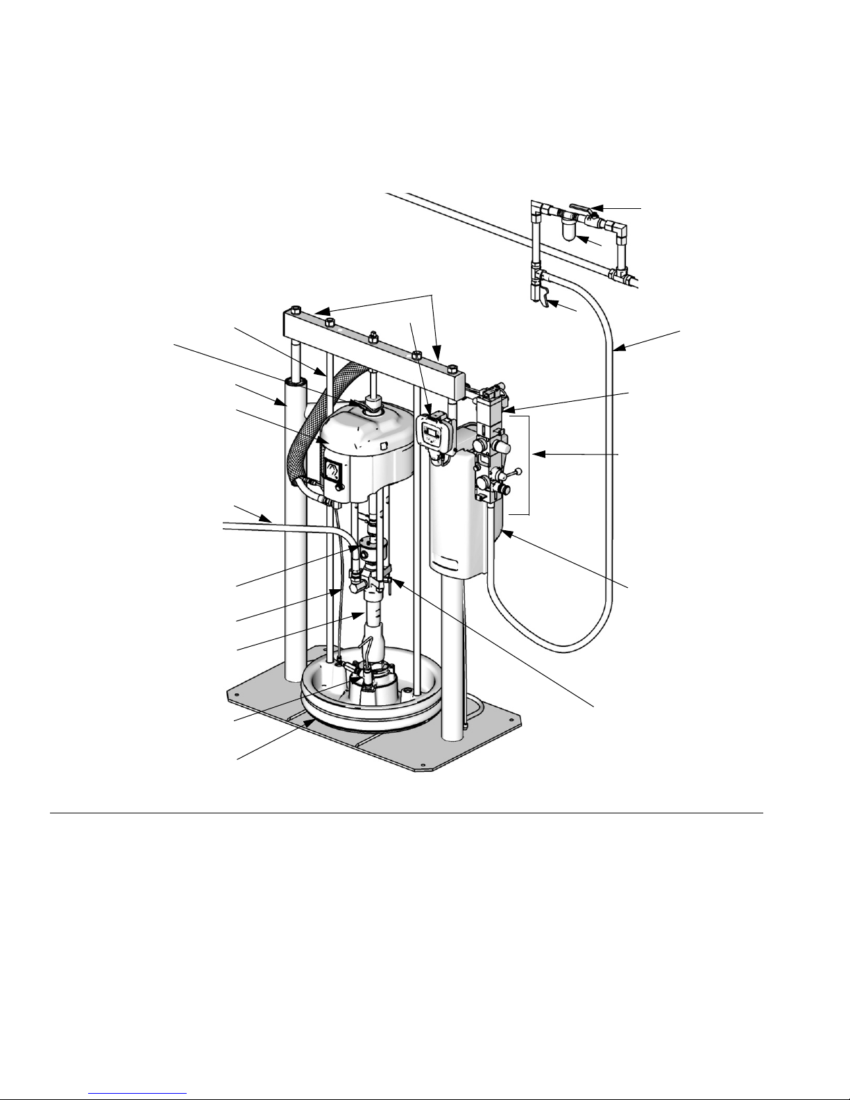
D200 3 in. and D200s 6.5 in. Dual Post
W
H
(Note: Do not use motor
lift ring to lift entire
system.)
CM14BA Model
Shown
N
A
B
S
R
M
Lift Locations
E
V
U
T
X
G
K
C
J
D
FIG.1
Key:
A Ram Assembly
B Air Motor
C Displacement Pump
D Platen
F Remote DataTrak (single ram systems) or
Display Module (tandem systems)
G Integrated Air Controls (see F
H Air Motor Lift Ring
J Platen Bleed Port
K Power Supply Box (under shrouding)
M Blowoff Air Supply Line
IG.3)
P
TI10430a
N Platen Lift Rod
P Pump Bleed Valve
R Enclosed Wet Cup
S Fluid Line (not supplied)
T Air Line (not supplied)
U Air Line Drain Valve (not supplied)
V Air Filter (not supplied)
W Bleed Type Air Shutoff Valve (not supplied)
X Air Motor Solenoid
10 313527ZAD
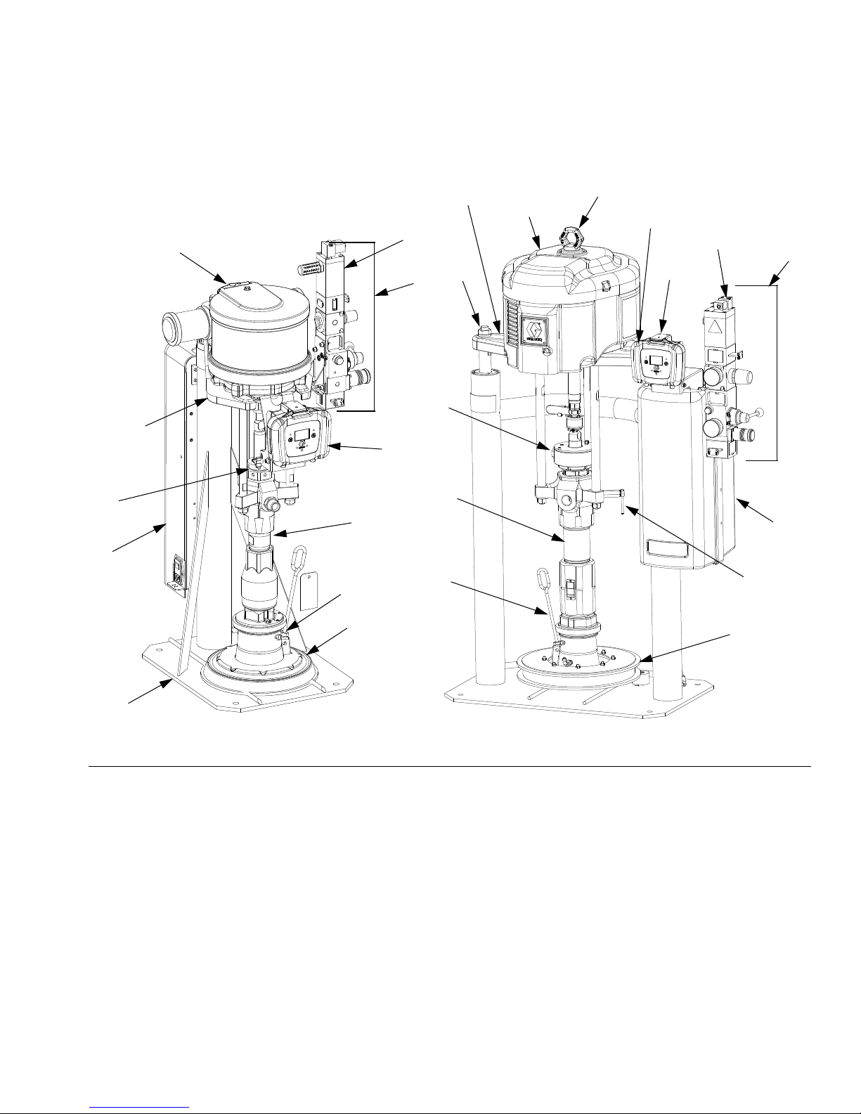
S20 3 in. Single Post and D60 3 in. Dual Post
Component Identification
Model CM9HLB Shown
B
Lift
Location
R
K
Model CM2MRY Shown
Lift Location
B
H
(Note: Do not use motor
lift ring to lift entire
system.)
Lift Location
X X
G
A
F
G
R
F
C
C
K
A
r_255648_313527_5a
FIG.2
Key:
A Ram Assembly
B Air Motor
C Displacement Pump
D Platen
F Remote DataTrak (single ram systems) or
Display Module (tandem systems)
G Integrated Air Controls (see F
H Lift Ring
J Platen Bleed Port
K Power Supply Box (under shrouding)
P Pump Bleed Valve
R Enclosed Wet Cup
S Fluid Line (not supplied, see F
T Air Line (not supplied, see F
U Air Line Drain Valve (not supplied, see F
IG.3)
IG.1)
IG.1)
J
D
IG.1)
J
r_255648_313527_6a
V Air Filter (not supplied, see F
W Bleed Type Air Shutoff Valve (not supplied, see F
X Air Motor Solenoid
IG.1)
P
D
IG.1)
313527ZAD 11
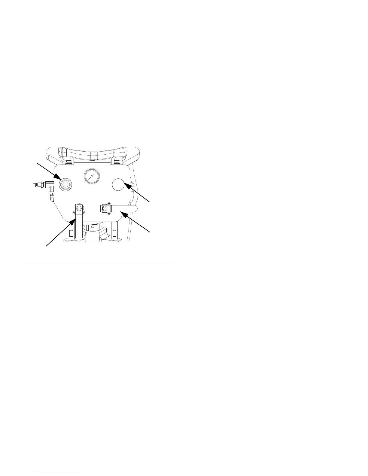
Component Identification
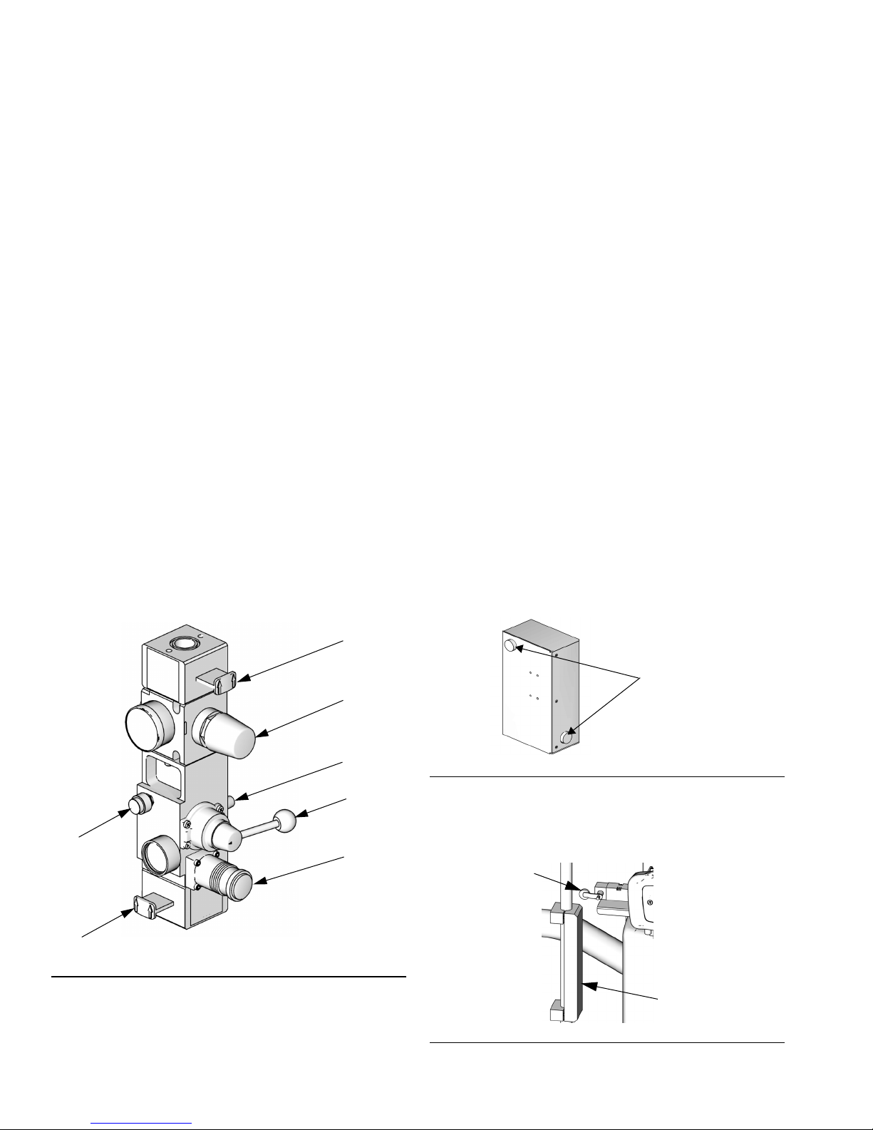
Integrated Air Control Module
D200, D200s, D60, and S20 Models
The integrated air controls include:
• Main air slider valve (BA): turns air on and off to
the system. When closed, the valve relieves pressure downstream.
• Ram air regulator (BB): controls ram up and down
pressure and blowoff pressure.
• Ram director valve (BC): controls ram direction.
• Exhaust port with muffler (BD)
• Air motor regulator (BE): Controls air pressure to
motor.
• Air motor slider valve (BF): turns air on and off to
the air motor. When closed, the valve relieves air
trapped between it and the air motor. Push the valve
in to shutoff. Remote DataTrak: The air solenoid,
the air motor slider valve (BF), and the main air
slider valve (BA) must be open for air to flow. (See
Remote DataTrak Setup, in manual 312371)
• Blowoff button (BG): turns air on and off to push
the platen out of an empty drum.
Integrated Air Line Accessories
See FIG.1.
• Air line drain valve (U)
• Air line filter (V): removes harmful dirt and moisture from compressed air supply.
• Second bleed-type air valve (W): isolates air line
accessories for servicing. Locate upstream from all
other air line accessories.
• Air relief valve (not visible): automatically relieves
excessive pressure.
2-Button Interlock Air Controls
D200i, D200si, and D60i Models
Units that have 2-Button Interlock controls have the following additional components:
• 2-Button Module: See manual 312374 for information.
• Roller switch (CA): shuts off air supply when it
contacts the bracket actuator. Operator must push
and hold buttons to resume ram movement.
BG
BA
FIG. 3. Integrated Air Control Module
ti10438a
BF
BE
BD
BC
BB
Activation
Buttons
ti10843a1
FIG.4
• Bracket actuator (CB): attaches to the platen lift
rod. When ram is near the top, actuator makes contact with the roller switch.
CA
CB
ti10846a
FIG.5
12 313527ZAD
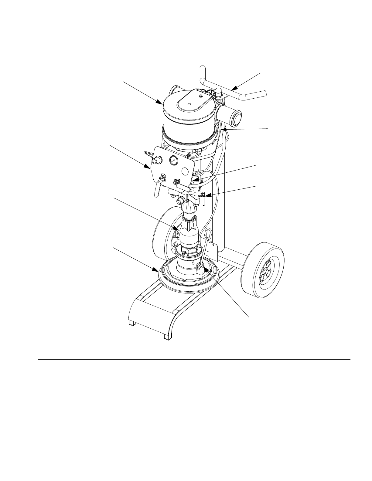
L20c 2in. Elevator
Component Identification
CM7B1G Model Shown
BF
BC
BD
BA
BB
Lift Location
R
P
FIG.6
Key:
BA Elevator Cart
BB Air Motor
BC Displacement Pump
BD Platen
BF Elevator and Pump Air Controls
J Platen Bleed Port
P Pump Bleed Valve
R Enclosed Wet Cup (behind air controls)
313527ZAD 13
J
r_257302_312376_1e
Component Identification
L20c 2 in. Air Controls
• Air motor regulator (DA): Controls air pressure to
motor.
• Blowoff button (DB): turns air on and off to push
the platen out of an empty drum.
• Air motor shutoff valve (DC): turns air on and off
to the air motor.
• Elevator director valve (DD): controls elevator
direction.
DA
DB
DD
DC
F
IG. 7: Elevator Air Controls
r_257302_312376_2e
Air and Fluid Hoses
Be sure all air hoses (AI) and fluid hoses (AH) are properly sized and pressure-rated for your system. Use only
electrically conductive hoses. Fluid hoses must have
spring guards on both ends. Use of a short whip hose
and a swivel between the main fluid hose and the
gun/valve allows freer gun/valve movement.
14 313527ZAD
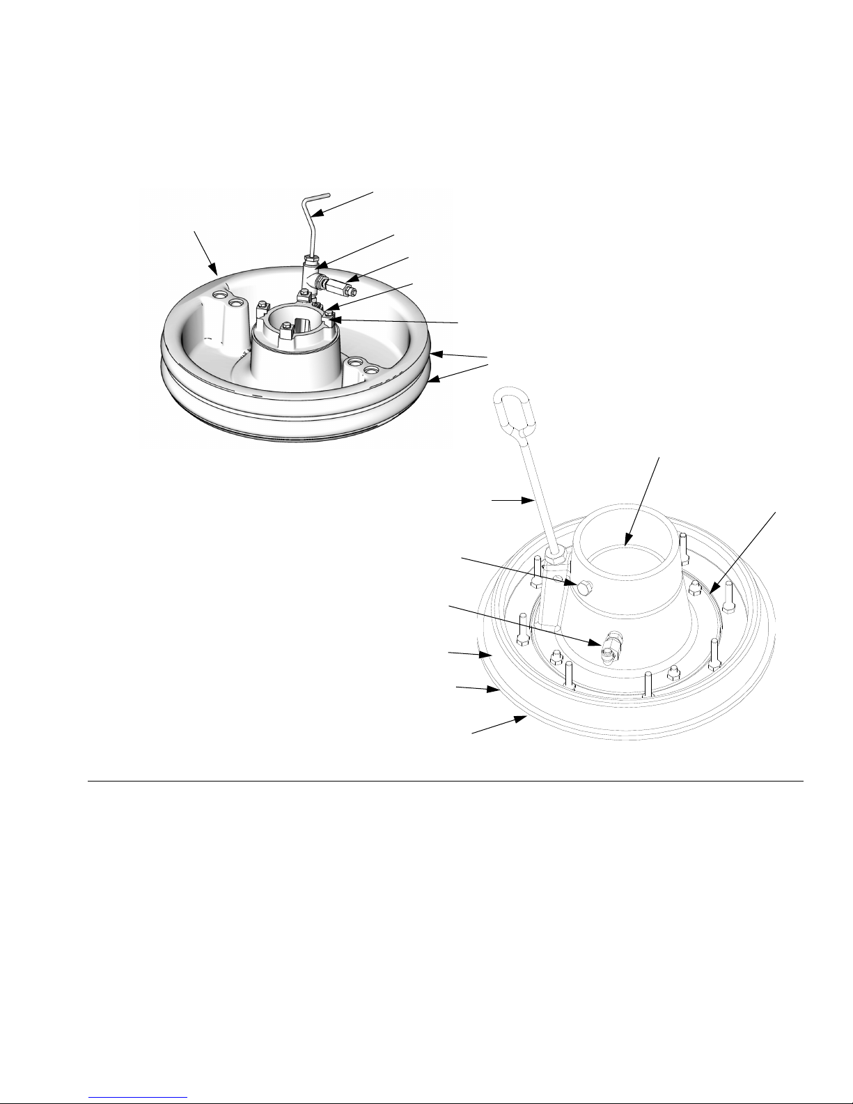
Platen Component Identification
Model 255664, 200 liter (55 gallon)
EK
Component Identification
EA
EL
TI10518A
EM
EH
EH
EM
EJ
EK
EB
Model 257727, 20 liter (5 gallon)
EP
EA
FIG.8
Key:
EA Plate
EB Wipers
EG Spacer
EH Cap Screws
EJ Clamps
EK Bleed Handle
EL Bleed Valve
EM Air Assist Body Check Valve
EN Wiper Plate (under wiper)
EP O-ring Seal
EG
EB
EN
r_255648_313527_7a
313527ZAD 15
Before Beginning Repair
Before Beginning Repair
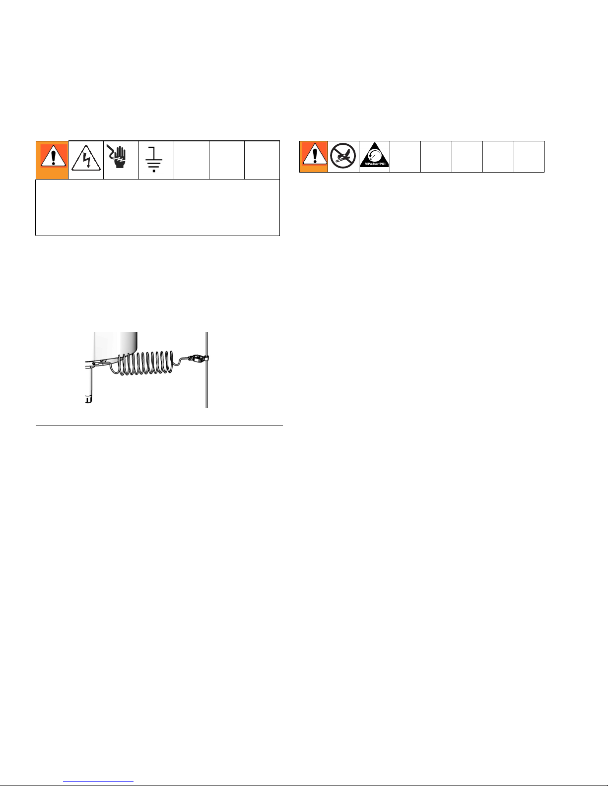
Grounding
The equipment must be grounded. Grounding
reduces the risk of static and electric shock by providing an escape wire for the electrical current due to
static build up or in the event of a short circuit.
Pump: use a ground wire and clamp. Loosen grounding
lug locknut and washer. Insert one end of a 1.5 mm2(12
ga) minimum ground wire into the slot in lug and tighten
the locknut securely. Connect the other end of the wire
to a true earth ground.
ti8250a
F
IG.9
Pressure Relief Procedure
1. Lock the gun/valve trigger.
2. For D200s, D200, S20, and D60 Air Controls: See
FIG. 3, page 12.
a. Close the air motor slider valve (BF) and the
main air slider valve (BA).
b. Set the ram director valve to DOWN. The ram
will slowly drop.
c. Jog the director valve (BC) up and down to
bleed air from ram cylinders.
3. For L20c Air Controls: See FIG. 7, page 14.
a. Close the air motor valve (DC) and the elevator
director valve (DD). The ram will slowly drop.
4. Unlock the gun/valve trigger.
Air hoses: use only electrically conductive hoses.
Fluid hoses: use only electrically conductive hoses.
Air compressor: follow manufacturer’s recommenda-
tions.
Spray gun/dispense valve: ground through connection
to a properly grounded fluid hose and pump.
Fluid supply container: follow local code.
Object being sprayed: follow local code.
All solvent pails used when flushing: follow local
code. Use only conductive metal pails placed on a
grounded surface. Do not place the pail on a nonconductive surface, such as paper or cardboard, which
interrupts the grounding continuity.
To maintain grounding continuity when flushing or
relieving pressure, always hold a metal part of the
gun/valve firmly to the side of a grounded metal pail,
then trigger the gun/valve.
5. Hold a metal part of the gun/valve firmly to the side
of a grounded metal pail, and trigger the gun/valve
to relieve pressure.
6. Lock the gun/valve trigger.
7. Open the fluid line drain valve and the pump bleeder
valve (P). Have a container ready to catch the drainage.
8. Leave the pump bleeder valve (P) open until ready
to spray again.
If you suspect that the spray tip/nozzle or hose is completely clogged, or that pressure has not been fully
relieved after following the steps above, very slowly
loosen the tip guard retaining nut or hose end coupling
and relieve pressure gradually, then loosen completely.
Now clear the tip/nozzle or hose.
16 313527ZAD
Maintenance Procedures
Flush Before Using Equipment
The pump was tested with lightweight oil, which is left in
the fluid passages to protect parts. To avoid contaminating your fluid with oil, flush the pump with a compatible
solvent before use. See your pump manual for flushing
directions.
Maintenance Procedures
To reduce the risk of serious injury whenever you are
instructed to relieve pressure, always follow the
Pressure Relief procedure.
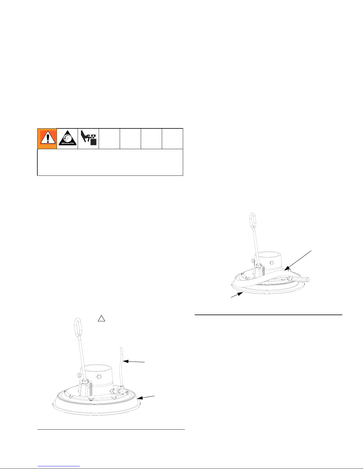
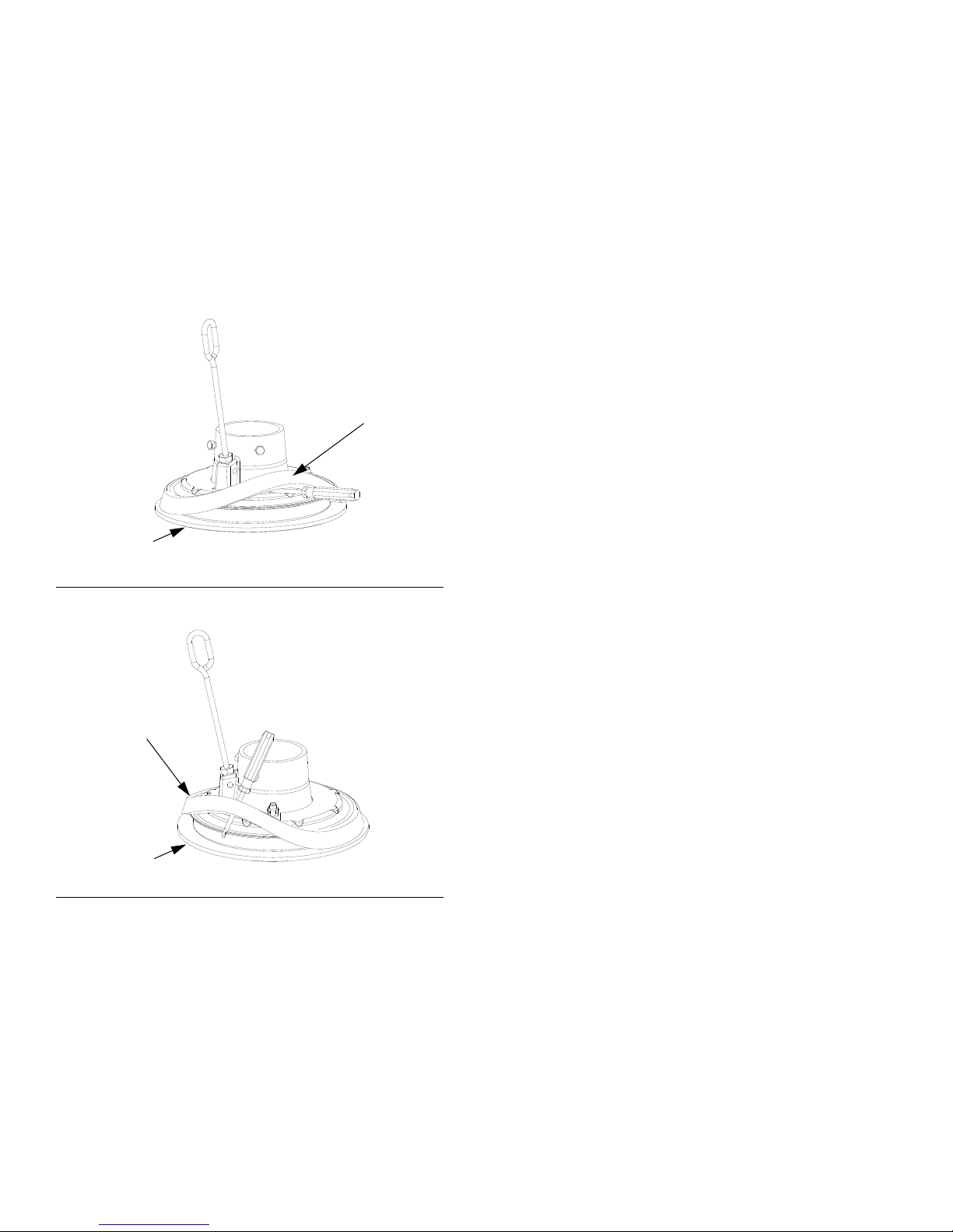
Platen Maintenance
See FIG. 10. If the platen does not come out of the pail
easily when the pump is being raised, the air assist tube
(F), or check valve may be plugged. A plugged valve
prevents air from reaching the underside of the plate to
assist in raising it from the pail.
Adjust Spacers
Use Platen with Tapered and Straight Sided
Pails
The platen is supplied for use with 20 liter (5 gallon), 30
liter (8 gallon), and 60 liter (16 gallon) straight sided
pails, but only single wiper platens can be easily modified for use with tapered pails.
Use platen with tapered pails
1. Working from the bottom, use screwdriver to pry
spacer (EG) loose. Work spacer upward completely
above the flange of the platen. See F
2. By hand, angle spacer (EG) and work it off the plate,
pulling it down over the flange and bottom wipers
(EB). See FIG. 12.
3. Save spacer (EG), as it is required for other applications.
IG. 11.
1. Relieve pressure. Refer to parts illustration on page
58 and disassemble air assist valve as shown.
2. Clear air assist tube (F) in platen. Clean all parts of
valve and reassemble.
3. Remove bleed stick (EK) from platen. Push bleed
stick through bleed relieve ports to remove material
residue.
1
To use Model 255655 platens
with tapered pails, the spacer
(EG) must be removed.
F
EG
r_255468_313527_33a
FIG.11
EB
EG
r_255468_313527_30a
FIG.10
313527ZAD 17
Maintenance Procedures
Use platen with straight sided pail
1. Ensure large diameter of spacer (EG) is facing
down. Work spacer (EG) up over the platen by
hand completely above the flange of the platen. See
FIG. 12.
2. Working from the top, use screwdriver to position
spacer (EG) between flange and wipers (EB). See
IG. 13.
F
EG
EB
F
IG. 12: Sliding spacer
r_255468_313527_30a
Remove and Reinstall Wipers
Disassemble 20, 30, and 60 Liter Wiper
Assemblies
1. Remove wiper assembly; see FIG. 14:
a. For all single wiper platens: Remove two clips
(470) with needle nose pliers and remove platen
cover (469).
b. Remove eight nuts (459) that hold wiper assem-
bly to platen casting (451) and remove wiper
assembly.
c. See Reassemble 20, 30, and 60 Liter Wiper
Assemblies to change wiper sizes, styles, or a
complete wiper assembly.
2. Remove eight nuts (459) on wiper assembly.
3. Separate top plate (457), spacer (452), wiper(s)
(453), wiper support (454), and bottom plate (455).
4. Clean, inspect, and replace worn components.
EG
EB
FIG. 13: Installing Spacer
r_255468_313527_32a
18 313527ZAD
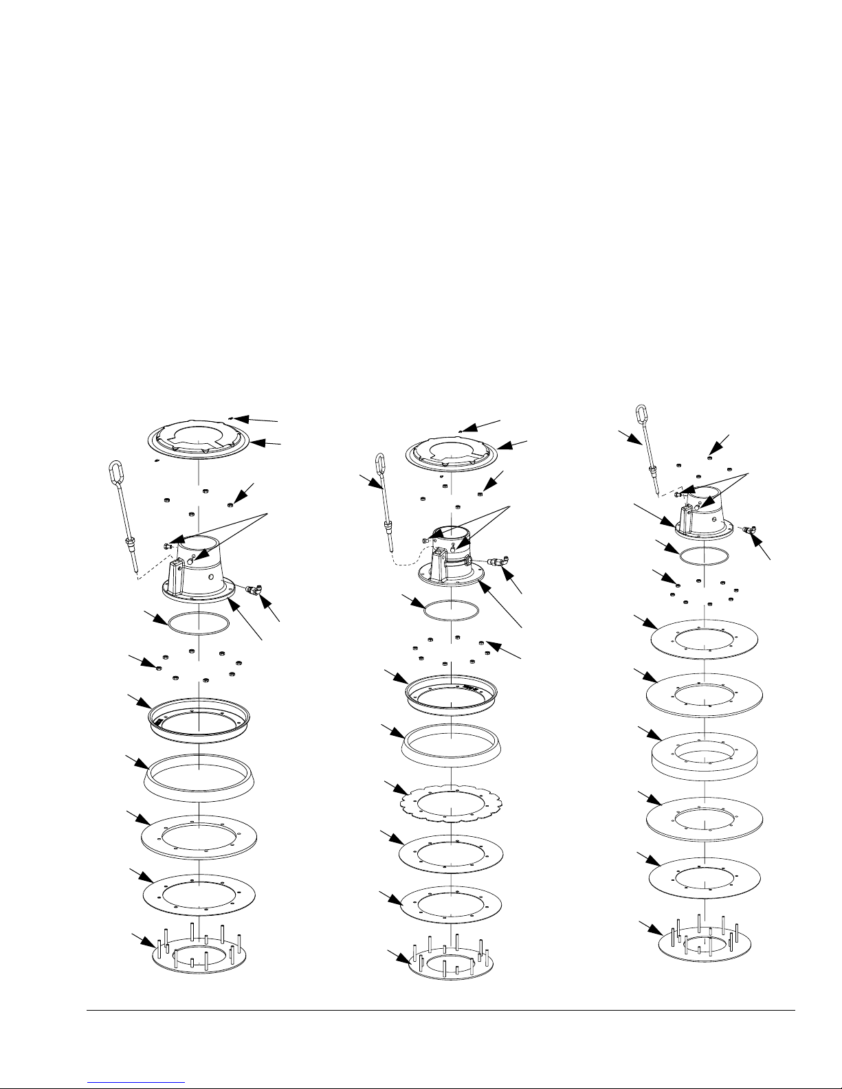
Maintenance Procedures
Reassemble 20, 30, and 60 Liter Wiper
Assemblies
1. Assemble wiper assembly.
a. For single wiper assemblies: Place bottom plate
(455) on flat surface. Place wiper support (454),
wiper (453), spacer (452), and top plate (457)
on bottom plate (455).
b. For single wiper assemblies with SST platens:
Place bottom plate (455) on flat surface. Place
wiper support (454), wiper (453), flowered wiper
support (460), PTFE spacer (452), and top plate
(457) on bottom plate (455).
Single Wiper Platen
470
469
459
462
461
c. For double wiper assemblies: Place bottom
d. Install eight nuts (409) on outer ring. Torque to
e. Replace o-ring (456), or install new o-ring under
f. Install platen casting (451). Tighten with four
Single Wiper with
SST Platen
plate (455) on flat surface. Place wiper support
(454), wiper (453), spacer (452), wiper (453)
and top plate (457) on bottom plate (455).
45 in-lbs (61 N•m).
platen casting (451). Use lubricant to hold in
place.
nuts (509).
Double Wiper Platen
470
469
459
462
461 459
462
451
459
457
452
453
454
455
456
451
465
457
452
460
453
454
455
456
465
451
459
457
453
452
453
454
455
456
459
465
F
IG. 14: Single and Double Wiper Assemblies
313527ZAD 19
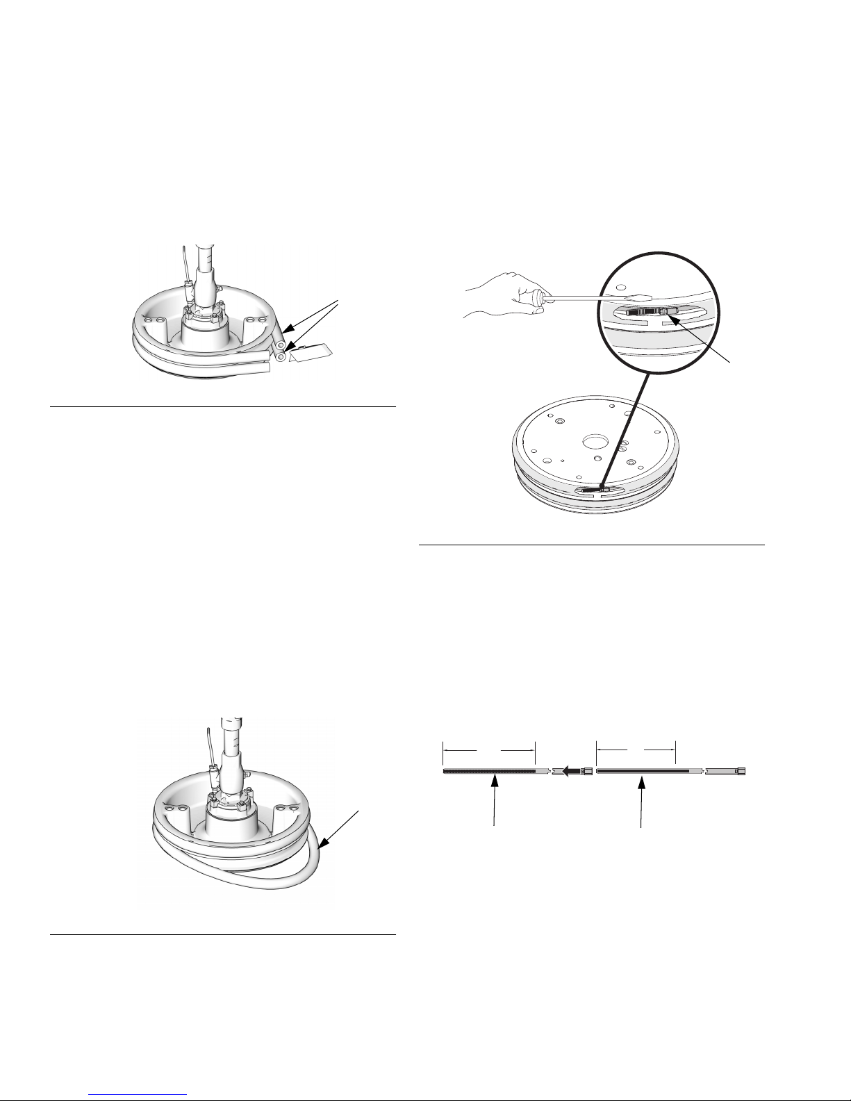
Maintenance Procedures
Remove 30 and 55 Gallon Platen Wipers
1. To replace worn or damaged wipers (EB), raise
platen up out of drum. Remove drum from base.
Wipe fluid off of platen.
2. Cut top and bottom wipers with knife and remove
from platen. See FIG. 15.
EB
TI10613A
FIG.15
Reinstall 30 and 55 Gallon Platen Wipers
1. Using a wooden or plastic tool to prevent damage to
the wiper (EB), clean all material from seal grooves.
2. Working from the bottom, angle one wiper (EB) over
back of platen. See FIG. 16.
Remove 55 Gallon Platen Hose Wipers
1. To replace worn or damaged wipers (EB), raise
platen up out of drum. Remove drum from base.
Wipe fluid off of platen.
2. Loosen ends of banding (410) with jack screw. See
FIG. 17.
410
WLD
FIG.17
3. Insert wiper (EB) in top groove and run front of wiper
into groove.
4. 55 gallon wiper only: Insert second wiper (EB) in
lower groove and run front of wiper into groove.
5. Lubricate outside of wiper with lubricant compatible
with material being pumped. Check with material
supplier.
EB
TI10614A
FIG.16
Reinstall 55 Gallon Plate Hose Wipers
1. Clean all material from the seal grooves. Lubricate
ram plate grooves before assembly.
2. Assemble two bands (410) together. Align one end
of band about 9 in. from jack screw and tape
attached band. Install screw jack in slot.
1
WLD
1
20 313527ZAD
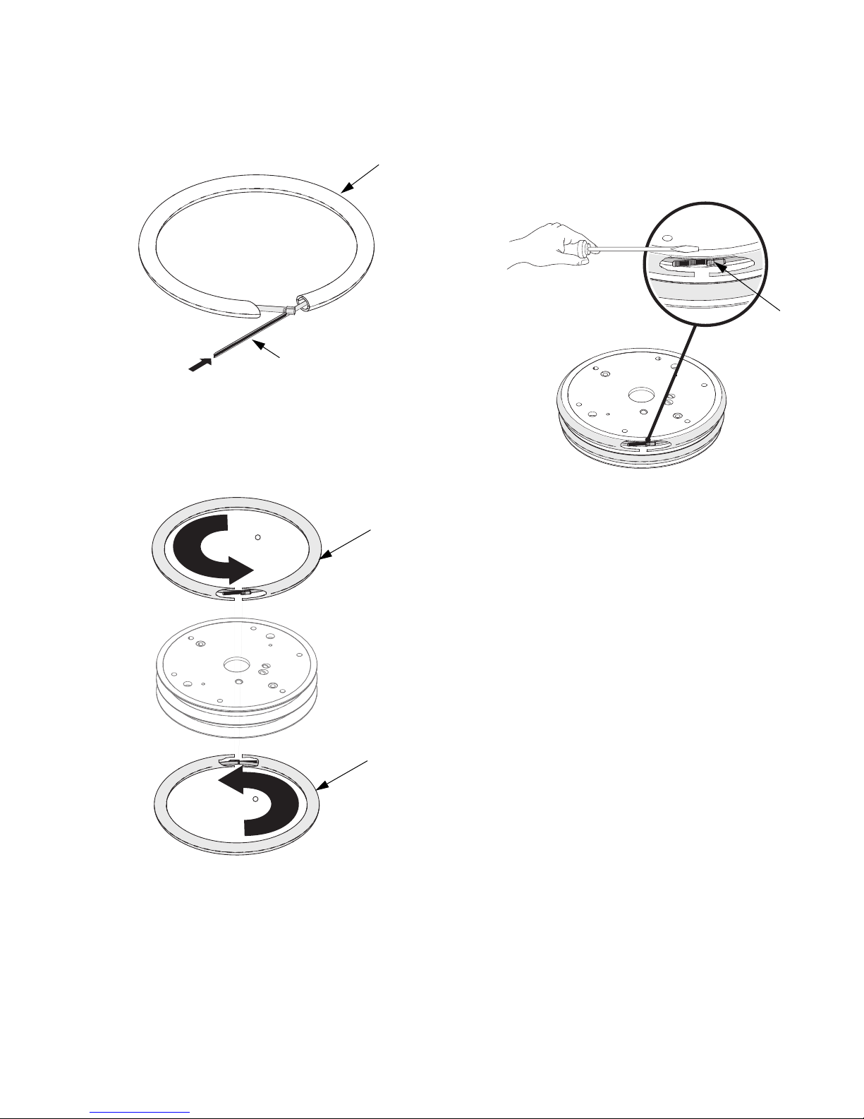
Maintenance Procedures
3. Insert jack screw end of band (410) into hose (408
or 409) and push completely through hose.
408, 409
410 (x2)
NOTE: To prevent material from potentially leaking past
both hoses, ensure hose (408,409) seams are 90°-180°
apart, and not on top of each other.
WLD
408
4. Lubricate outside of hoses (408,409) and place on
upper or lower groove on plate. Adjust hose and
band so that the angled ends of hose press against
each other. Tighten two ends of banding (410)
together with jack screw.
410
WLD
5. Work hose to completely close gap at the ends.
313527ZAD 21
409
WLD
 Loading...