

Page 1
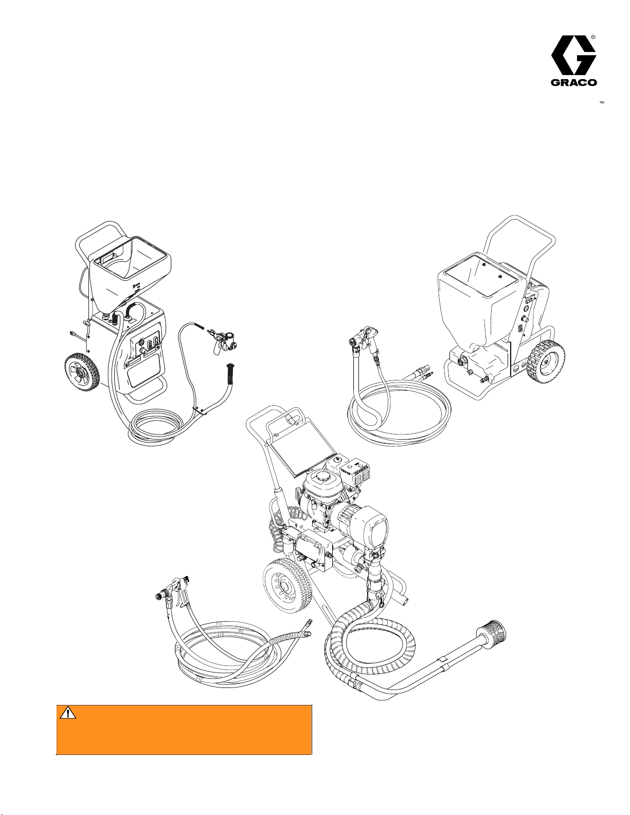
Texture Sprayers
First choice when
quality counts.
Electrical & Mechinical
Troubleshooting Manual
Rev. C 10/11 /07
ti4305a
WARNING
This manual should only be used
by a qualified Service Technician.
Page 2

Table of Contents
Basic meter terminology and testing procedures.................................................................................................3-9
Electric Texture Sprayers
RTX 650 and TX 65:
• Motor will not start.................................................................................................................................. 10
RTX 900,1250 and TX 90,125:
• Motor will not start.................................................................................................................................. 11
RTX 750 and RTX 1000:
• Motors will not start ........................................................................................................................... 12,13
• RotoFlex Motor will not start..................................................................................................................14
• Air Compressor Motor will not start ....................................................................................................... 15
RTX 1500:
Operational and troubleshooting:
• Power cord plugged in and Power Switch Off ....................................................................................... 16
• Power cord plugged in and Power Switch ON........................................................................................ 17
• Power cord plugged in and Power Switch ON and IN the PRIME MODE ............................................ 18
• Power cord plugged in and Power Switch ON and Gun Trigger Closed ................................................ 19
• Power cord plugged in and Power Switch ON and Spray Gun Trigger Open......................................... 20
Gas Texture Sprayers
TexSpray 1030 FC:
• Operational Overview ............................................................................................................................. 21
• Pump will not prime................................................................................................................................22
• Pump will not spray................................................................................................................................. 23
GM 1030 TexSpray:
• Operational and troubleshooting ............................................................................................................. 24
Page 3
BASIC ELECTRICAL TERMINOLOGY
3
In any discussion of electricity, there are three basic terms you will need to understand.
CURRENT
VOLTAGE
RESISTANCE
CURRENT:
Current is the movement of the electrical charge.
Current Flows through the wires from the power source to the load.
Current is measured in AMPERES (AMPS, A or I). See Figure 1.
NOTE: Meter is only clamped around one wire.
ON/OFF
Switch
Ref
58
FIGURE 1
Power
Plug
from Motor
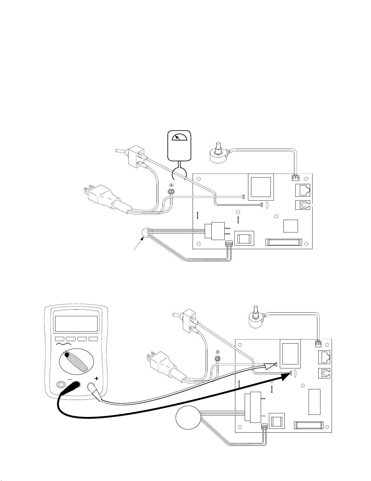
VOLTAGE:
Voltage is the force that causes current to fl ow in a circuit.
Voltage is measured in VOLTS (V or E). See Figure 2.
Black
ON/OFF
Switch
120 AC
V
Power
Ref
Plug
Green
Red (+)
Black (–)
58
White
Black
Black
Potentiometer
Ref 37
Black
FIGURE 2
Green
(+)
Red
Motor
Black (–)
White
Page 4
BASIC ELECTRICAL TERMINOLOGY
4
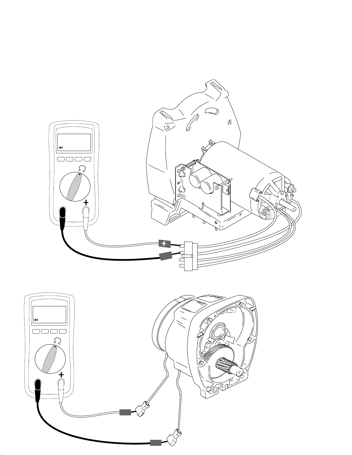
RESISTANCE:
Resistance is anything that causes an opposition to the fl ow of current in a circuit.
Resistance is used to control the amount of voltage and/or amperage in a circuit.
Resistance is measured in OHMS - Ω. See Figure 3.
A common component check would be motor and clutch field windings.
FIGURE 3
Known Value
Known Value
��
Black
Red
--
Yel
Yel
��
+
-
Page 5
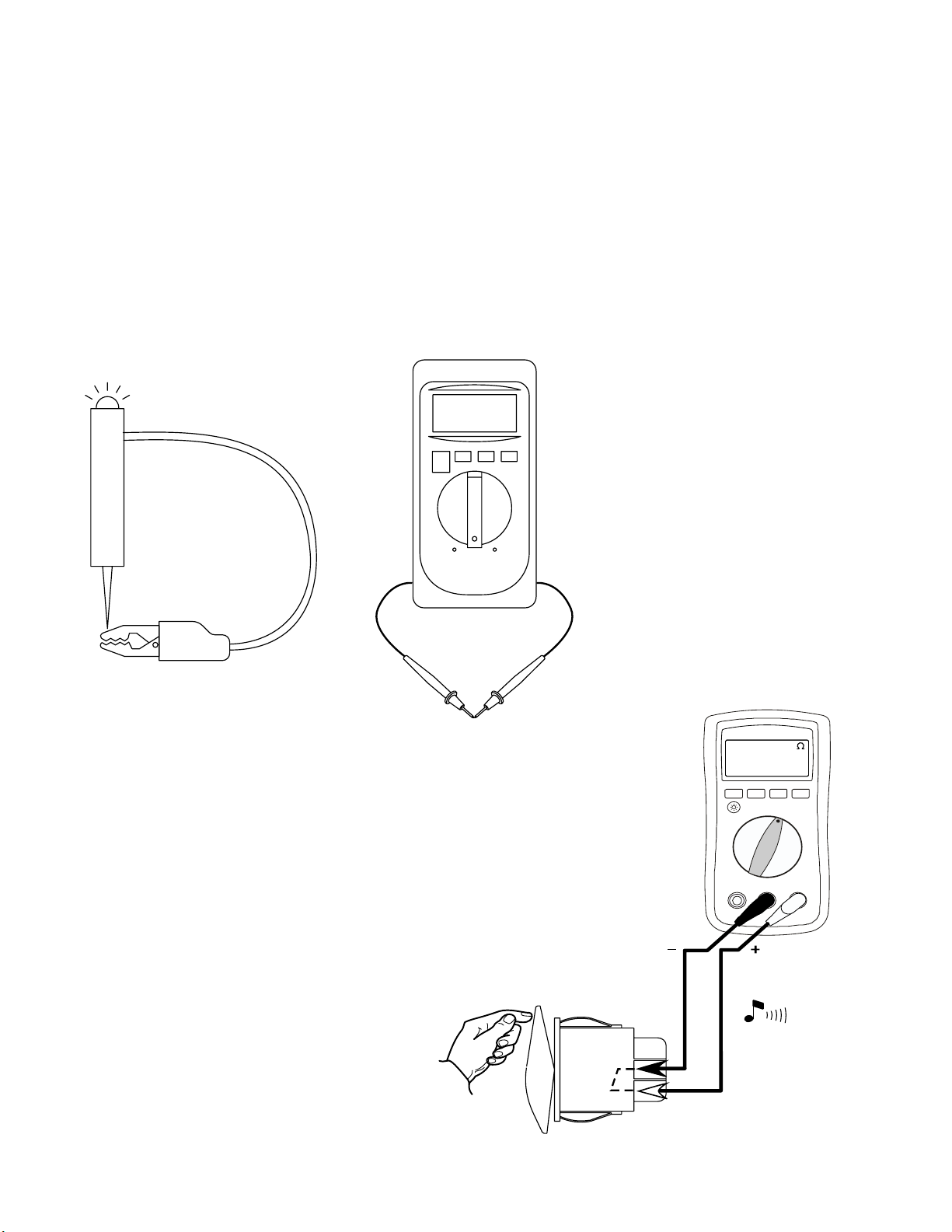
CONTINUITY TESTING
5
Checking “continuity” is one of the most common tests in electrical troubleshooting. Continuity is the ability of a wire or electrical component to
conduct
current. When you use a continuity tester, you connect a circuit (the continuity tester) that you know works, to a wire or a component that
may or may not work.
Continuity testers are available at almost any hardware store.
A volt-ohmmeter or VOM can also be used to check continuity. This meter can be purchased at most electrical or electronic supply stores.
To test a component for continuity:
1 Check the tester by connecting the leads.
* If using a test light the light should turn on.
The continuity tester will tell you if the wire or component is capable of conducting current.
* If using a digital volt-ohmmete
r, the screen should show 00 if OL appears the meter needs to be repaired.
0.000
SWITCH TESTING-ROCKER
Common test procedure for a SPST Switch:
Page 6
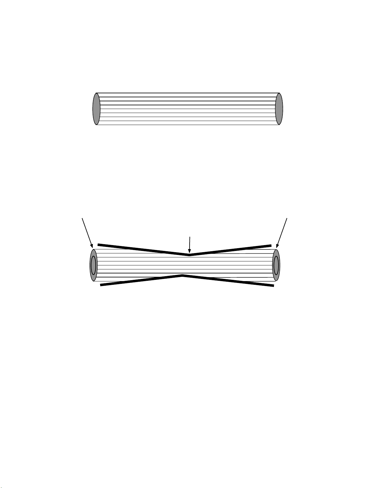
WIRE CONTINUITY TESTING
6
Continuity testing will “NOT” fi
120
Vac input static voltage and drops to 119Vac load voltage.
A good piece of wire will carry line and load voltage.
Damaged / Fragmented Wire
nd wire fragmentation!!
Example:
Damaged / Fragmented Wire
Pinched Wire
120 Vac input static voltage and drops to 76Vac load voltage.
Other causes:
Poor stripping of outer insulation.
Poor crimp.
A defective piece of wire may carry line voltage but will “NOT” carry load voltage
Page 7
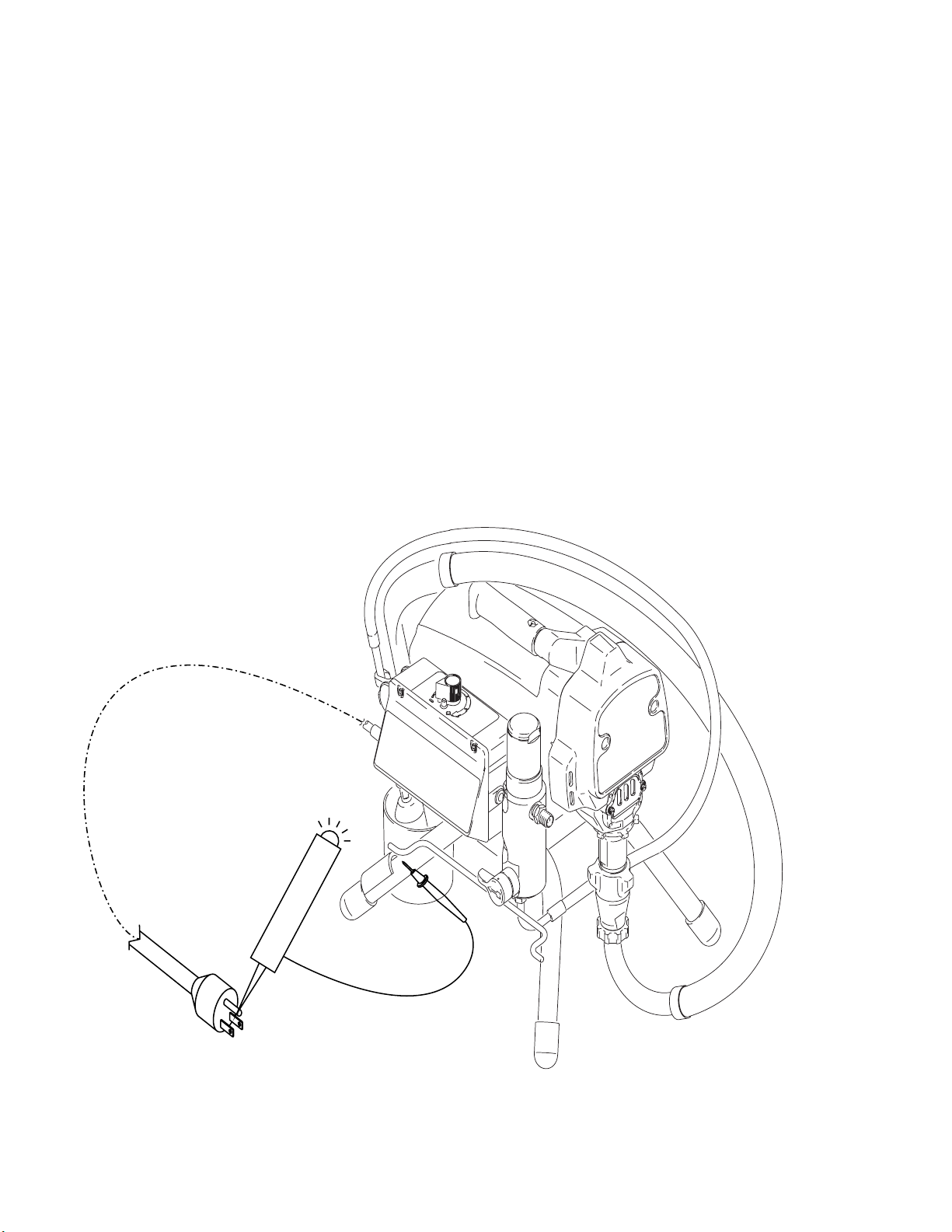
GROUND TESTING
7
Improper installation or alteration of grounding plug could results in risk of electric shock, fire or explosion that could cause serious injury or death.
The other function of the grounding plug is to protect the control board from static build up. If the plug is missing this could cause permanent damage
to the control board.
Every corded electric sprayer that comes into your shop for repair should be tested as described below, to make sure that it is properly grounded.
Pull
the machine’s plug out of the wall outlet and connect one lead from a DC continuity test light or a VOM to the (round) gro
plug.
NOTE:
If the ground terminal is broken o
Touch the test light (or VOM) leads to several bare metal surfaces on the body of the machine. If the light (or meter) indicates continuity, the machine
is
properly grounded. If the light (or meter) doesn’t indicate continuity trace through the ground (green) wiring on the machine to determine where
the break is.
ff of the plug, install a new plug.
und
terminal on the
Page 8
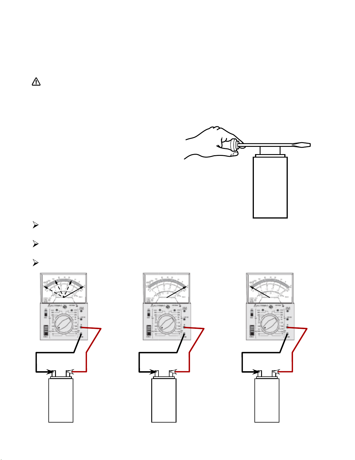
CAPACITOR TESTING:
8
A capacitor is an electrical component that stores electricity. Capacitors are usually used to help start a motor or make a motor run more eff
The following instructions can be used to test any capacito
r.
WARNING!
A CAPACITOR CAN SHOCK YOU EVEN WHEN A MACHINE IS UNPLUGGED. NEVER TOUCH CAPACITOR TERMINALS WITH
YOUR
FINGERS. ALWAYS USE TOOLS WITH INSULATED HANDLES. NEVER DISCHARGE A CAPACITOR NEAR FLAMMABLE
LIQUIDS OR
1 Visually inspect the capacitor for leaks, mechanically damage or loose terminals. Replace it if any of these problems exist.
2 Unplug the machine and remove the capacitor(s).
If capacitor(s) are attached to the control board the test can not be perormed.
3 “SEE ABOVE WARNING” Using a screwdriver with
insulated handles, hold so that the blade contacts the
capacitor terminals as shown in Fig.
“discharge” the capacito
4 Put a volt-Ohm meter on the R X 100 scale.
5 While watching the meter, connect the 2 leads to the 2 terminals on the capacitor.
If the capacitor is good, the meter needle will go to the right (toward 0 resistance) (Fig. 1), then to the left (toward - maximum resistance)
VAPORS.
A. This will
r.
FIG. A
Capacitor
If the meter needle goes all the way to the right and stays there, the capacitor is defective.(Fig.2)
If the meter needle stays all the way to the left (doesn't move at all when connected to the capacitor), the capacitor is defective.(Fig. 3)
GOOD BAD BAD
Page 9

RECTIFIER
9
(See Fig. 1) Now we come to the most popular application of the diode: rectifcation. Simply rectifcation is the conversion of alternating
(AC) to direct current (DC). This almost always involves the use of some device that only allows one-way fl ow of electrons.
current
we have seen, this is exactly what a diode does.
As
RECTIFIER TESTING:
FI
DC
G. 1
AC
AC
0.000
+
DC
The following instructions can be used to test any bridge rectifer.
Use a DC continuity test light or a VOM (on the R x 100 scale) for all tests.
Disconnect all wires from the recti
1 Connect test leads as shown in Figure A. If the meter beeps, the rectifer is
defective. If the meter does not beep, go to the next step.
2 Connect test leads as shown in Figure B. If the meter does not beep, the
recti
fer is defective. If the meter beeps, go to the next step.
3 Connect test leads as shown in Figure C. If the meter beeps, the rectifer is
defective. If the meter does not beep, go to the next step.
4 Connect test leads as shown in Figure D. If the meter does not beep, the
fer is defective. If the meter beeps, go to the next step.
recti
5 Connect test leads as shown in Figure E. If the meter beeps, the rectifer is
defective. If the meter does not beep, go to the next step.
6 Connect test leads as shown in Figure F. If the meter does not beep, the rectifer is defective. If the meter beeps, go to the next step.
7 Connect test leads as shown in Figure G. If the meter beeps, the rectifer is defective. If the meter does not beep, go to the next step.
8 Connect test leads as shown in Figure H. If the meter does not beep, the rectife r is defective. If the meter beeps, the rectifer is good.
OL OL
fer.
-
0.000
FIG. A FIG. B FIG. C FIG. D
OL OL
FIG
. E FIG. F FIG. G FIG. H
0.000
0.000
Page 10

Motor will not run.
10
RTX 650 and TX 65
See step 1.Do you have
over 100 AC volts?
YES
See step 2. Do you have
over 100 AC volts ?
YES
See step 3.Do you have
over 100 AC volts?
YES
Replace Motor
NO
replace the
power Cord.
Repair or
NO
power switch.
Check the 3amp
NO
Fuse, if ok repalce
fuse holder.
Replace the
Whit
e
Bla
Green
110-120 AC
V
--
ck
--
Wh
Step 1
Power switch ON.
Cord plugged in.
Meter on AC Volts
Fuse
Red
Red
Power Cord
ite
Bla
110-120 AC
V
Step 2
Power switch ON.
Cord plugged in.
Meter on AC Volts
--
++
Fuse
++
ck
ck
Bla
Green
ck
Red
Red
Bla
--
Whit
e
Wh
Power Cord
ite
Green
n
Gree
Chassis Ground
Moto
ON/OFF
r
Fuse
Swit
ch
110-120 AC
V
Step 3
Power switch ON.
Cord plugged in.
Meter on AC Volts
--
Black
Red
Fuse
Whit
Bla
ck
e
Wh
ite
Red
Power Cord
Green
Bla
ck
Red
Red
ck
Bla
++
--
Whit
e
Wh
Power Cord
ite
Page 11

See step 1.Do you have
11
over 100 AC volts?
YES
See step 2. Do you have
ver 100 AC volts?
o
Motor will not run.
RTX 900, 1250 and TX 90, 125
Repair or
NO
NO
replace the
power Cord.
110-120 AC
V
--
Replace the
power switch.
Power Cord
Step 1
Power switch ON.
Cord plugged in.
Meter on AC Volts
Green
Green
White
Bla
--
Wire (GND)
ck
Switch
Bla
Green
White
ck
++
r
Moto
YES
Replace Motor
Green
Wire (GND)
Power Cord
ck Wire
Bla
Switch
White Wire
r
Moto
110-120 AC
V
--
Power Cord
Step 2
Power switch ON.
Cord plugged in.
Meter on AC Volts
Green
Green
White
Black
--
Switch
Wire (GND)
White
ck
Bla
Green
++
r
Moto
Page 12

RotoFlex Motor or Compressor motor will not run.
12
RTX 750 and RTX 1000
See pages 00, for the steps.
See step 1.Do you have
over 100 AC volts?
YES
See step 2. Do you have
over 100 AC volts?
YES
See step 3.Do you have
over 100 AC volts?
YES
See step 4.Do you have
over 100 AC volts?
YES
See step 5. Do you have
over 100 AC volts?
NO
NO
NO
NO
NO
Repair or
r
wire or wire splice.
Repair or
replace the
power Cord.
Repair or
r
eplace White
wire or wire splice.
Repair or
r
eplace Black wire
from power cord to
power switch.
Replace the
power switch.
eplace Black
Page 13

RotoFlex Motor or Compressor motor will not run.
13
RTX 750 and RTX 1000
110-120 AC
V
--
WHITE
WHITE
BLACK
Step 1
Cord plugged in.
Wires connected.
Meter on AC Volts
GREEN
POWER
--
++
BLACK
CORD
CAPACITOR
BLACK
110-120 AC
V
--
WHITE
--
WHITE
BLACK
Step 2
Cord plugged in.
Wires connected.
Meter on AC Volts
GREEN
POWER
CORD
++
110-120 AC
V
--
POWER
SWITCH
--
Step 3
Power switch ON.
Cord plugged in.
Wires connected
to power switch.
Meter on AC Volts
SELECTOR
SWITCH
BLUE
BLACK
WHITE
BLACK
++
POWER
CORD
POWER
SWITCH
110-120 AC
V
--
BLUE
SELECTOR
SWITCH
BLUE
GREEN
GROUND
GREEN
BLACK
AIR COMPRE
BLACK
Step 5
Power switch ON.
Cord plugged in.
Black Wire unplugged
from Selector switch.
Meter on AC Volts
MOTOR
SSOR
YEL
LOW
POWER
SWITCH
--
BLACK
WHITE
SELECTOR
SWITCH
++
WHITE
BLACK
GREEN
BLACK
BLUE
WHITE
POWER
CORD
POWER
CORD
110-120 AC
V
--
POWER
SWITCH
--
BLACK
Step 4
Power switch ON.
Cord plugged in.
Wires connected
to power switch.
Meter on AC Volts
SELECTOR
SWITCH
BLUE
++
POWER
CORD
WHITE
BLACK
Page 14

RotoFlex Motor motor will not run.
14
RTX 750 and RTX 1000
Does the
Air Compressor
motor run?
YES
See step 1.
o you have
D
over 100 AC volts?
YES
See step 2.
o you have
D
over 100 AC volts?
YES
See Capacitor
test. Does the
Capacitor test ok?
YES
See Motors
NO
will not run
Repair or
NO
r
wire or wire splice.
Repair or
NO
r
wire or wire splice.
NO
eplace White
eplace Black
Replace
the
Capacitor
.
110-120 AC
V
Step 1
Power switch ON.
Cord plugged in.
Wires connected
to selector switch.
--
Selector switch ON.
Meter on AC Volts
POWER
SWITCH
SELECTOR
SWITCH
--
110-120 AC
V
Step 2
Power switch ON.
Cord plugged in.
Wires connected
to selector switch.
BLUE
--
BLACK
To Motor
Yellow
.
WHITE
++
WHITE
GREEN
POWER
CORD
POWER
SWITCH
Selector switch ON.
Meter on AC Volts
SELECTOR
SWITCH
--
BLUE
BLACK
Replace the
Rotoflex Motor.
POWER
SWITCH
SELECTOR
SWITCH
BLUE
BLACK
BLUE
BLACK
CAPACITOR
BLACK
GREEN
GROUND
GREEN
AIR COMPRE
BLACK
MOTOR
SSOR
YEL
BLACK
LOW
WHITE
GREEN
WHITE
BLACK
To Motor
Yellow
WHITE
POWER
CORD
++
WHITE
BLACK
GREEN
POWER
CORD
Page 15

Air Compressor Motor motor will not run.
15
RTX 750 and RTX 1000
Does the
Rotoflex motor
run?
YES
See step 1.
o you have
D
over 100 AC volts?
YES
See step 2.
o you have
D
over 100 AC volts?
YES
Replace the
Air Compressor.
See Motors
NO
will not run
Repair or
NO
r
wire or wire splice.
Repair or
r
NO
wire or wire splice.
.
eplace White
eplace Black
BLACK
110-120 AC
V
--
--
CAPACITOR
BLACK
POWER
SWITCH
BLACK
To Motor
Yellow
WHITE
Step 1
Power switch ON.
Cord plugged in.
Meter on AC Volts
SELECTOR
SWITCH
BLUE
++
GREEN
POWER
CORD
WHITE
BLACK
110-120 AC
V
--
POWER
SWITCH
BLACK
To Motor
Yellow
Step 2
Power switch ON.
Cord plugged in.
Meter on AC Volts
SELECTOR
SWITCH
--
WHITE
BLUE
++
WHITE
GREEN
POWER
CORD
POWER
SWITCH
SELECTOR
SWITCH
BLUE
BLUE
BLACK
MOTOR
GREEN
GROUND
GREEN
AIR COMPRE
BLACK
SSOR
YEL
LOW
WHITE
BLACK
GREEN
POWER
CORD
WHITE
BLACK
Page 16

N/O
16
Pow
117693
1500 Electrical and Air Ladder Diagram
RTX
Power
Load Blk Neutral Wht
cord plugged in and Power Switch Off
120V
Main
er Switch
Motor/Air
Compressor
M
Main
Valve Coil
287326
15D559
Valve
mbly
asse
.
Grnd
Open in
Prime
N/C Pr
Co
Mode
imer Switch 119064
Air
mpressor
Air Cooler
Coil
Exhausted
Air
N/C Air Flow
Sensor Switch
287326
Cylinder Valve
Coil
15D560
Air Flow
Air Flow
Gun Valve
The Switch will remain closed
until
air flow is present. The
Gun being triggered or a Air
Leak
will cause the ball to lift up
open the circuit.
and
KEY
Electrical Switching Circuit
Air Flow
15D559
assembly
Valve
Sensor Switch
45psi
Exhausted
Air
Cylinder V
Coil Vo
to be exhausted and the weight of the
motor to
remove tension on the Roto Flex Hose.
alve 15D560:With
ltage Applied. This will allow air
push the cylinder rod in and
Air
Regu
lator
Exhausted
Air
Coil
Cylinder Valve
Air
Page 17

N/O
17
Pow
RTX 1500 Electrical and Air Ladder Diagram
Power
Load Blk Neutral Wht
cord plugged in and Power Switch
120V
Main
er Switch
Motor/Air
Compressor
M
117693
Valve Coil
Main
287326
15D559
Valve
mbly
asse
ON
Grnd
Prime
N/C Pr
Co
mpressor
Air Cooler
Open in
Mode
imer Switch 119064
Air
Coil
Exhausted
Air
N/C Air Flow
Sensor Switch
287326
Cylinder Valve
Coil
15D560
Air Flow
Air Flow
Gun Valve
The Switch will remain closed
until
Gun being triggered or a Air
Leak
Sensor Switch
air flow is present. The
will cause the ball to lift up
and
open the circuit.
KEY
Electrical Load Circuit
Air Flow
15D559
assembly
Valve
45psi
ted
Exhaus
Air
Cylinder V
With Coil Voltage Applied. This will
allow
motor
tens
alve 15D560:
air to be exhausted and the weight of the
to push the cylinder rod in and remove
ion on the Roto Flex Hose.
Coil
Regu
Air
Air
lator
Exhausted
Air
Page 18

Power
18
RTX 1500 Electrical and Air Ladder Diagram
cord plugged in and Power Switch ON and IN the PRIME MODE
Load Blk Neutral Wht
N/O
Pow
Main
er Switch
120V
Motor/Air
Compressor
Grnd
M
117693
Valve Coil
Main
287326
15D559
Valve
asse
mbly
Open in
Prime
Mode
N/C Pr
imer Switch 119064
Air
mpressor
Co
Air Cooler
Coil
Exhausted
Air
N/C Air Flow
Sensor Switch
287326
Cylinder Valve
15D560
Coil
45psi
Air Flow
Air Flow
Gun Valve
The Switch will remain closed
until
air flow is present. The
Gun being triggered or a Air
Leak
will cause the ball to lift up
and
open the circuit.
KEY
Electrical Switching Circuit
Air Flow
15D559
Valve
assembly
Sensor Switch
Cylind
er Valve 15D560 : With NoCoil
Voltage
cylinder
tens
.This will allow air to enter the
and push the cylinder rod out and put
ion on the Roto Flex Hose.
Exhaus
Air
ted
Coil
Air
Regu
Air
lator
Exhausted
Air
Page 19

Power
19
N/O
Pow
117693
RTX 1500 Electrical and Air Ladder Diagram
cord plugged in and Power Switch ON and Gun Trigger Closed
Load Blk Neutral Wht
120V
Main
er Switch
Motor/Air
Compressor
M
Valve Coil
Main
287326
15D559
Valve
mbly
asse
Grnd
Prime
N/C Pr
Co
mpressor
Air Cooler
Open in
Mode
imer Switch 119064
Air
Coil
Exhausted
Air
N/C Air Flow
Sensor Switch
287326
Cylinder Valve
Coil
15D560
Air Flow
Air Flow
Gun Valve
The Switch will remain closed
until
Gun being triggered or a Air
Leak
Electrical Switching Circuit
Sensor Switch
air flow is present. The
will cause the ball to lift up
and open the circuit.
KEY
Air Flow
15D559
assembly
Valve
45psi
Exhaus
ted
Air
Cylinder V
With Coil Voltage Applied. This will allow
air to be exhausted and
motor
tens
alve 15D560:
the weight of the
to push the cylinder rod in and remove
ion on the Roto Flex Hose.
Coil
Air
Regu
Air
lator
Exhausted
Air
Page 20

Power
20
RTX 1500 Electrical and Air Ladder Diagram
cord plugged in and Power Switch ON and Spray Gun Trigger Open
Load Blk Neutral Wht
N/O
Pow
Main
er Switch
120V
Motor/Air
Compressor
Grnd
M
117693
Valve Coil
Main
287326
15D559
Valve
asse
mbly
.
Open in
Prime
Mode
N/C Pr
imer Switch 119064
Air
mpressor
Co
Air Cooler
Coil
Exhausted
Air
N/C Air Flow
Sensor Switch
287326
Cylinder Valve
15D560
Coil
Air Flow
Air Flow
Gun Valve
The Switch will remain closed
air flow is present. The
until
Gun being triggered or a Air
Leak
will cause the ball to lift up
and
open the circuit.
KEY
Electrical Switching Circuit
Air Flow
15D559
assembly
Valve
Sensor Switch
45psi
ted
Exhaus
Air
Cylinder V
With NoCoil Voltage.This will allow air
to enter the cylinder and push the cylinder rod
out and put tension on the Roto Flex Hose.
alve 15D560 :
Coil
Air
Regu
Air
lator
Exhausted
Air
Page 21

1030FC Electrical and Air Ladder Diagram
21
Rotary Switch in the Off .
Engine
Power
Not
Used
Compressor
Air
Regulator
0-125psi
Air
Clutch Coil
Thermistor
Exhausted
Air
Wht. Com.
Blk. Off
Blu. Prime
15B671
ROTORY
SWITCH
234234
Control Board
Control Board must
see 30psi to operate!
Flow Sensor Kit
234232
Flow Switch
Gun Valve
Red High
Engine
12-18VAC
Yel. Med.
Grn. Low
The Flow Switch will remain
open until air flow is present.
The Gun being triggered or
a Air Leak will cause the
piston to move towards the
magnetic reed switch and
close the circuit. Once the
Control Board senses the
closed circuit it will engage
the clutch and close the dump
valve.
Pinion
Assembly
245399
Mac Air Valve
15B683
Dump Valve
287127
Blue
Black
Air
No Coil Voltage. This will allow air to enter the
top Black air hose and force the dump valve
open and allow material to be pumped back to
the supply container.
Transducer:
Sends a signal to the control board for material
pressure and protects the sprayer from over
pressurizing. Shuts pump down at 1000psi!
Page 22

Engine
22
Power
Not
Used
Clutch Coil
Thermistor
1030FC Electrical and Air Ladder Diagram
Rotary Switch in the Prime Mode .
When the rotary switch is in the Prime position the Control Board
will send out 8-12VDC to the clutch and the pump will engage
and prime the system. Note: The dump valve remains open.
Wht. Com.
Blk. Off
Blu. Prime
15B671
ROTORY
SWITCH
234234
Control Board
Red High
Yel. Med.
Grn. Low
Engine
12-18VAC
Assembly
Pinion
245399
Compressor
Air
Regulator
0-125psi
Mac Air Valve
Air
15B683
Exhausted
Air
Control Board must
see 30psi to operate!
Flow Sensor Kit
234232
Flow Switch
Gun Valve
No Coil Voltage. This will allow air to enter the
top Black air hose and force the dump valve
open and allow material to be pumped back to
the supply container.
The Flow Switch should
remain open and have no
effect while the rotary switch
is in the prime mode. If the
dump valve remains closed
check the gun and air hose for
leaks, if no leaks are found,
unplug the flow switch from
the control board. If the dump
valve opens, replace flow
sensor kit 234232. If the dump
valve still remains closed
check the dump valve for a
blockage and the Mac Air
Valve for a stuck spool valve.
Blue
Dump Valve
287127
Air
Black
Transducer:
Sends a signal to the control board for material
pressure and protects the sprayer from over
pressurizing. Shuts pump down at 1000psi!
Page 23

1030FC Electrical and Air Ladder Diagram
23
Spraying Mode:
In order to spray the control board must senses 30psi or higher and the rotary switch must be in one
of the 3 settings Low/Med./High. When the spray gun is triggered the flow switch will close,
sending a signal to the control board. The control board will then send voltage out to the clutch
field to start the pump. At the same time voltage will be sent to the Mac air valve coil. The coil will
close the air valve changing the direction of the air flow to the dump valve. Air will now travel
through the blue hose to the back of the dump valve forcing it closed .When this occurs the
material will be forced out through the material hose.
Clutch CoilEngine Power
15B671
ROTORY
SWITCH
234234
Control Board
Red High
Yel. Med.
Grn. Low
Not
Used
Wht. Com.
Blk. Off
Blu. Prime
Thermistor
Engine
12-18VAC
Pinion
Assembly
245399
Compressor
Air
Regulator
0-125psi
Mac Air Valve
Air
15B683
Blue
Exhausted
Air
Black
Control Board must
see 30psi to operate!
Flow Sensor Kit
234232
Air
Flow Switch
Gun Valve
Gun Air
Nozzle
When Coil Voltage is present, the coil will close the
air valve changing the direction of the air flow to the
dump valve. Air will now travel through the blue
hose to the back of the dump valve forcing it closed
The Flow Switch will remain
open until air flow is present.
The Gun being triggered or
a Air Leak will cause the
piston to move towards the
magnetic reed switch and
close the circuit. Once the
Control Board senses the
closed circuit it will engage
the clutch and close the dump
valve.
Dump Valve
287127
Air
Transducer:
Sends a signal to the control board for material
pressure and protects the sprayer from over
pressurizing. Shuts pump down at 1000psi!
Page 24

GM 1030 Tex Sprayer
24
1. PRESSURE SWITCH (normal open) Closes when 30 psi of pressure is maintained.
2. Differentia l PRESURE SWITCH (normal open) Closes when 5 cfms of air flow is maintained or when a air leak is present.
3. Combination gauge and SAFTEY SWITCH (normal closed)Interrupts electrical flow to the clutch stopping pumping
(not engine) when pressure reaches 1000 psi. .
4. BRIDGE RECIFIER converts AC voltage from the engine lighting coil to DC voltage which energizes the clutch.
5. 4 WAY VALVE (active when main switch is in the spray mode and switches 1 and 2 are closed) Controls air to dump
cylinder, positioning piston so as to close off the dump outlet on the dump cylinder enabling material to be sprayed.
( When power is off 4-Way valve returns to the dump position relieving pressure.
Red
Red
Under Pressure
Switch
Red from Engine
Engine
Blue
Blue
Yellow
Red
2
Flow
N.C.
N.O.
Switch
1
Black to Clutch
White to Clutch
Main Switch
Red
in OFF postion
Red
Red
NC
Blue
Com.
Red
Red
Red
Com
NO
Red
1
Under
Pressure
Switch
Flow
Switch
3
Pressure
Gauge with built
in Over pressure
switch.
Brown
Black
Blue
Spray
Blue
2
5
4 Way
Soleniod Valve
Prime
Rectifier
Black
Blue
3
External
Pressure
Switch
4
DC +
+
AC
White
Brown
Black
GROUND
AC
-
AC
4
Rectifier
DC -
GROUND
Red
(+)
(-)
5
4 Way
Soleniod
Valve
Black
AC
Clutch Coil
White
 Loading...