

Page 1
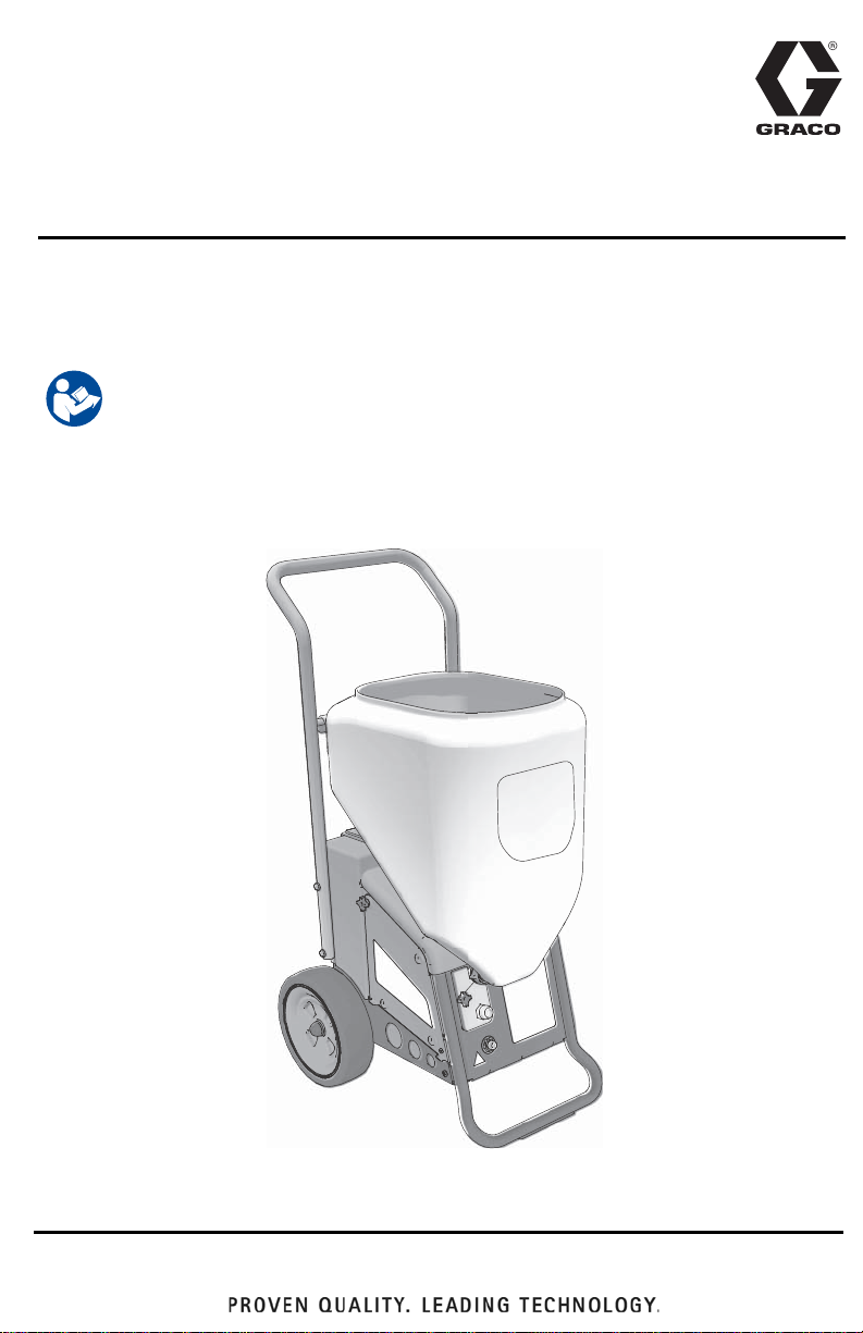
Operation, Parts
RTX1400 & RTX2000
Interior Texture Sprayers
For water-Based Materials Only.
Models: RTX1400si & RTX2000pi
70 psi (4.8 bar, 0.48 MPa) Maximum Working Pressure
Important Safety Instructions
Read all warnings and instructions in this manual and related manuals.
Be familiar with the controls and the proper usage of the equipment.
Save these instructions.
Related Manuals
RTX1400si Gun – 311777 RTX2000pi Gun – 3A3373
3A3258D
EN
ti27336a
Use only genuine Graco replacement parts.
The use of non-Graco replacement parts may void warranty.
Page 2

Contents
Contents
Models . . . . . . . . . . . . . . . . . . . . . . . . . . . . . . . . . . . . . . . . . . . . . . . . . . . . . . . . . . . . . . . 3
Warnings . . . . . . . . . . . . . . . . . . . . . . . . . . . . . . . . . . . . . . . . . . . . . . . . . . . . . . . . . . . . . 4
Component Identification . . . . . . . . . . . . . . . . . . . . . . . . . . . . . . . . . . . . . . . . . . . . . . . . 7
RTX1400si . . . . . . . . . . . . . . . . . . . . . . . . . . . . . . . . . . . . . . . . . . . . . . . . . . . . . . . . . 7
RTX2000pi . . . . . . . . . . . . . . . . . . . . . . . . . . . . . . . . . . . . . . . . . . . . . . . . . . . . . . . . . 8
Preparation . . . . . . . . . . . . . . . . . . . . . . . . . . . . . . . . . . . . . . . . . . . . . . . . . . . . . . . . . . . 9
Pressure Relief Procedure . . . . . . . . . . . . . . . . . . . . . . . . . . . . . . . . . . . . . . . . . . . . . 9
Grounding . . . . . . . . . . . . . . . . . . . . . . . . . . . . . . . . . . . . . . . . . . . . . . . . . . . . . . . . . 9
Power Requirements . . . . . . . . . . . . . . . . . . . . . . . . . . . . . . . . . . . . . . . . . . . . . . . . . 9
Extension Cords . . . . . . . . . . . . . . . . . . . . . . . . . . . . . . . . . . . . . . . . . . . . . . . . . . . . 9
Auxiliary Air Compressor . . . . . . . . . . . . . . . . . . . . . . . . . . . . . . . . . . . . . . . . . . . . . 10
Generator Requirements . . . . . . . . . . . . . . . . . . . . . . . . . . . . . . . . . . . . . . . . . . . . . 10
Soft Start/Smart Start™ System (RTX2000pi only) . . . . . . . . . . . . . . . . . . . . . . . . . 10
Setup . . . . . . . . . . . . . . . . . . . . . . . . . . . . . . . . . . . . . . . . . . . . . . . . . . . . . . . . . . . . . . . 11
Mixing Material . . . . . . . . . . . . . . . . . . . . . . . . . . . . . . . . . . . . . . . . . . . . . . . . . . . . . . . 13
Operation . . . . . . . . . . . . . . . . . . . . . . . . . . . . . . . . . . . . . . . . . . . . . . . . . . . . . . . . . . . . 15
Texture Spraying . . . . . . . . . . . . . . . . . . . . . . . . . . . . . . . . . . . . . . . . . . . . . . . . . . . 15
Recommended Nozzle Selection Charts . . . . . . . . . . . . . . . . . . . . . . . . . . . . . . . . . 15
Adjusting the System . . . . . . . . . . . . . . . . . . . . . . . . . . . . . . . . . . . . . . . . . . . . . . . . 15
Shutdown and Cleanup . . . . . . . . . . . . . . . . . . . . . . . . . . . . . . . . . . . . . . . . . . . . . . . . 17
Clean Material Hopper . . . . . . . . . . . . . . . . . . . . . . . . . . . . . . . . . . . . . . . . . . . . . . . 18
Transporting Sprayer . . . . . . . . . . . . . . . . . . . . . . . . . . . . . . . . . . . . . . . . . . . . . . . . 19
Maintenance . . . . . . . . . . . . . . . . . . . . . . . . . . . . . . . . . . . . . . . . . . . . . . . . . . . . . . . . . 20
Texture Hoses . . . . . . . . . . . . . . . . . . . . . . . . . . . . . . . . . . . . . . . . . . . . . . . . . . . . . 20
Tips . . . . . . . . . . . . . . . . . . . . . . . . . . . . . . . . . . . . . . . . . . . . . . . . . . . . . . . . . . . . . 20
Caring for Sprayer . . . . . . . . . . . . . . . . . . . . . . . . . . . . . . . . . . . . . . . . . . . . . . . . . . 20
Troubleshooting . . . . . . . . . . . . . . . . . . . . . . . . . . . . . . . . . . . . . . . . . . . . . . . . . . . . . . 21
RTX1400si Sprayer . . . . . . . . . . . . . . . . . . . . . . . . . . . . . . . . . . . . . . . . . . . . . . . . . . . . 25
RTX1400si Sprayer Parts List . . . . . . . . . . . . . . . . . . . . . . . . . . . . . . . . . . . . . . . . . 27
RTX2000pi Sprayer . . . . . . . . . . . . . . . . . . . . . . . . . . . . . . . . . . . . . . . . . . . . . . . . . . . . 28
RTX2000pi Sprayer Parts List . . . . . . . . . . . . . . . . . . . . . . . . . . . . . . . . . . . . . . . . . 30
Compressor Parts . . . . . . . . . . . . . . . . . . . . . . . . . . . . . . . . . . . . . . . . . . . . . . . . . . . . . 32
Compressor Parts List . . . . . . . . . . . . . . . . . . . . . . . . . . . . . . . . . . . . . . . . . . . . . . . 33
Wiring Diagram . . . . . . . . . . . . . . . . . . . . . . . . . . . . . . . . . . . . . . . . . . . . . . . . . . . . . . . 34
RTX1400si . . . . . . . . . . . . . . . . . . . . . . . . . . . . . . . . . . . . . . . . . . . . . . . . . . . . . . . . 34
RTX2000pi . . . . . . . . . . . . . . . . . . . . . . . . . . . . . . . . . . . . . . . . . . . . . . . . . . . . . . . . 34
Technical Specifications . . . . . . . . . . . . . . . . . . . . . . . . . . . . . . . . . . . . . . . . . . . . . . . 35
Graco Standard Warranty . . . . . . . . . . . . . . . . . . . . . . . . . . . . . . . . . . . . . . . . . . . . . . 37
Graco Information . . . . . . . . . . . . . . . . . . . . . . . . . . . . . . . . . . . . . . . . . . . . . . . . . . . . . 38
2 3A3258D
Page 3

Models
110474
Certified to
CAN/CSA
C22.2 No. 68
Conforms to
UL 1450
VAC Model
RTX1400si
RTX1400si RentalHD
Models
17H572
17P189
120
USA
RTX2000pi
RTX2000pi Rental
RTX2000pi RentalHD
17H573
17H574
17K301
3A3258D 3
Page 4
Warnings
Warnings
The following warnings are for the setup, use, grounding, maintenance, and repair of this
equipment. The exclamation point symbol alerts you to a general warning and the hazard
symbols refer to procedure-specific risks. When these symbols appear in the body of this
manual or on warning labels, refer back to these Warnings. Product-specific hazard symbols
and warnings not covered in this section may appear throughout the body of this manual
where applicable.
GROUNDING
This product must be grounded. In the event of an electrical short circuit, grounding reduces
the risk of electric shock by providing an escape wire for the electric current. This product is
equipped with a cord having a grounding wire with an appropriate grounding plug. The plug
must be plugged into an outlet that is properly installed and grounded in accordance with all
local codes and ordinances.
• Improper installation of the grounding plug is able to result in a risk of electric
shock.
• When repair or replacement of the cord or plug is required, do not connect the
grounding wire to either flat blade terminal.
• The wire with insulation having an outer surface that is green with or without
yellow stripes is the grounding wire.
• Check with a qualified electrician or serviceman when the grounding instructions
are not completely understood, or when in doubt as to whether the product is
properly grounded.
• Do not modify the plug provided; if it does not fit the outlet, have the proper outlet
installed by a qualified electrician.
• This product is for use on a nominal 120V circuit and has a grounding plug similar
to the plugs illustrated be low.
• Only connect the product to an outlet having the same configuration as the plug.
• Do not use an adapter with this product.
Extension Cords:
• Use only a 3-wire extension cord that has a groundin g plug and a grounding
receptacle that accepts the plug on the product.
• Make sure your extension cord is not damaged. If an extension cord is necessary
use 12 AWG (2.5mm
2
) minimum to carry the current that the product draws.
• An undersized cord results in a drop in line voltage and loss of power and
overheating.
4 3A3258D
Page 5
Warnings
FIRE AND EXPLOSION HAZARD
Flammable fumes, such as solvent and paint fumes, in work area can ignite or
explode. To help prevent fire and explosion:
• Do not spray or clean with flammable materials. Use water-based materials only.
• Use equipment only in well ventilated area.
• Sprayer generates sparks. When flammable liquids are used near the sprayer,
keep sprayer at least 20 feet (6.1 meters) away from explosive vapors.
• Keep work area free of debris, including solvent, rags and gasoline.
• Ground all equipment in the work area. See Grounding instructions.
• Keep a working fire extinguisher in the work area.
EQUIPMENT MISUSE HAZARD
Misuse can cause death or serious injury.
• Always wear appropriate gloves, eye protection, and a respirator or mask when
painting.
• Do not operate or spray near children. Keep children away from equipment at all
times.
• Do not overreach or stand on an unstable support. Keep effective footing and
balance at all times.
• Stay alert and watch what you are doing.
• Do not operate the unit when fatigued or under the influence of drugs or alcohol.
• Do not kink or over-bend the material or air hoses.
• Do not expose the hose to temperatures or to pressures in excess of those
specified by Graco.
• Do not use the hose as a strength member to pull or lift the equipment.
• Do not alter or modify equipment. Alterations or modifications may void agency
approvals and create safety hazards.
• Make sure all equipment is rated and approved for the environment in which you
are using it.
BURN HAZARD
Equipment surfaces and fluid that is heated can become very hot during operation.
To avoid severe burns:
• Do not touch hot fluid or equipment.
ELECTRIC SHOCK HAZARD
This equipment must be grounded. Improper groundi ng, setup, or usage of the
system can cause electric shock.
• Turn off and disconnect power cord before servicing equipment.
• Connect only to grounded electrical outlets.
• Use only 3-wire extension cords.
• Ensure ground prongs are intact on power and extension cords.
• Do not expose to rain. Store indoors.
3A3258D 5
Page 6
Warnings
PRESSURIZED EQUIPMENT HAZARD
Fluid from the equipment, leaks, or ruptured components can splash in the eyes or
on skin and cause serious injury.
• Follow the Pressure Relief Procedure when you stop spraying/dispensing and
before cleaning, checking, or servicing equipment.
• Tighten all fluid connections before operating the equipment.
• Check hoses, tubes, and couplings daily. Replace worn or damaged parts
immediately.
MOVING PARTS HAZARD
Moving parts can pinch, cut, or amputate fingers and other body parts.
• Keep clear of moving parts.
• Do not operate equipment with protective guards or covers removed.
• Pressurized equipment can start without warning. Before checking, moving, or
servicing equipment, follow the Pressure Relief Procedure and disconnect all
power sources.
PLASTIC PARTS CLEANING SOLVENT HAZARD
Many solvents can degrade plastic parts and cause them to fail, which could cause
serious injury or property damage.
• Use only compatible water-based solvents to clean plastic structural or
pressure-containing parts.
• See Technical Data in this and all other equipment instruction manuals. Read
fluid and solvent manufacturer’s Safety Data Sheet (SDS) and
recommendations.
PERSONAL PROTECTIVE EQUIPMENT
Wear appropriate protective equipment when in the work area to help prevent serious injury,
including eye injury, hearing loss, inhalation of toxic fumes, and burns. This protective
equipment includes but is not limited to:
• Protective eyewear, and hearing protection.
• Respirators, protective clothing, and gloves as recommended by the fluid and
solvent manufacturer.
CALIFORNIA PROPOSITION 65
This product contains a chemical known to the State of California to cause cancer, birth defects
or other reproductive harm. Wash hands after handling.
6 3A3258D
Page 7
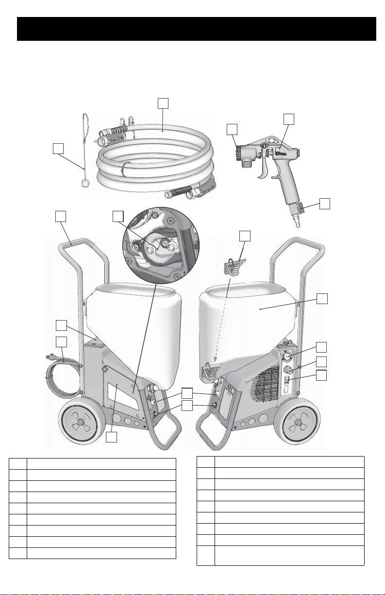
Component Identification
C
D
F
H
J
K
G
B
A
E
R
P
N
M
ti27337a
S
W
Y
Component Identification
RTX1400si
A
Handle
B
Toolbox
C
Power Cord
D
Pump Access Panel
E
RotoFlex™ II Pump
F
Pump Hose Outlet
G
Air Hose Outlet
H
Material Flow Gauge
J
Material Flow Control
3A3258D 7
K
ON/OFF Switch
M
Material Hopper
N
Burp Guard
P
Material/Air Hose
R
Material Thickness Gauge
S
Nozzle
W
Gun
Y
Air control valve
Model/Serial Tag (Not shown, located
on bottom of unit.)
Page 8
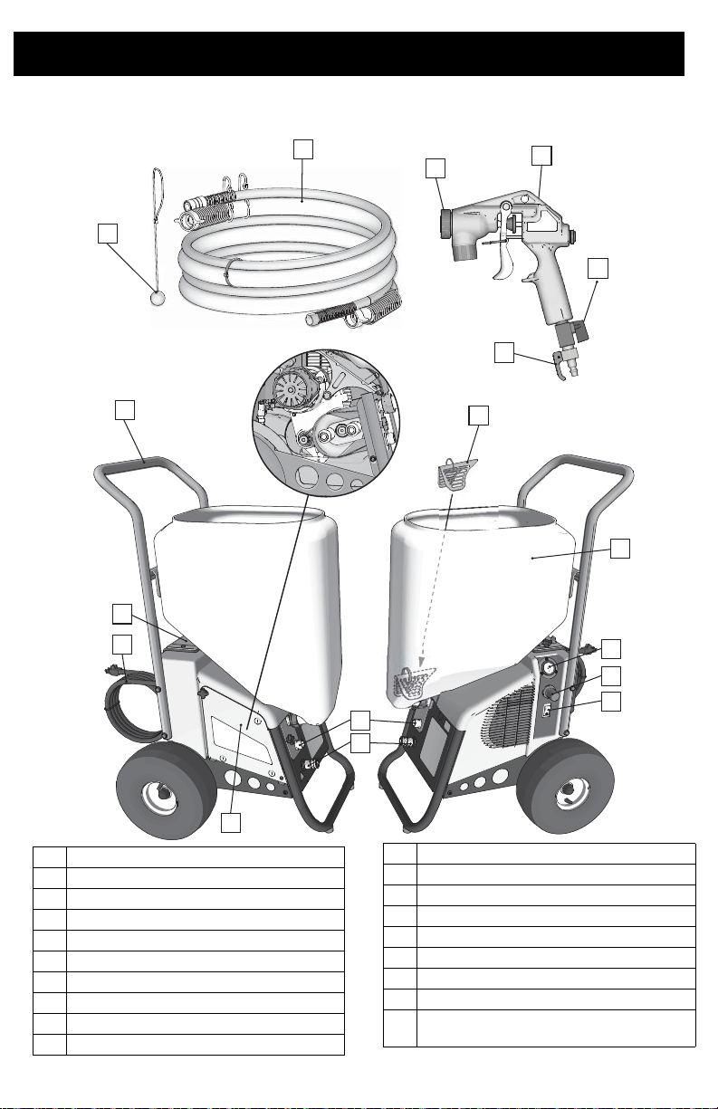
Component Identification
R
P
S
W
H
J
K
D
F
G
C
B
A
ti27338a
N
M
X
Y
RTX2000pi
A
Handle
B
Toolbox
C
Power Cord
D
Pump Access Panel
E
RotoFlex™ II Pump
F
Pump Hose Outlet
G
Air Hose Outlet
H
Material Flow Gauge
J
Material Flow Control
K
ON/OFF Switch
M
Material Hopper
N
Burp Guard
P
Material/Air Hose
R
Material Thickness Gauge
S
Nozzle & retaining ring
W
Gun
X
Prime Valve
Y
Air control valve
Model/Serial Tag (Not shown, located
on bottom of unit.)
8 3A3258D
Page 9
Preparation
ti27339a
ti27341a
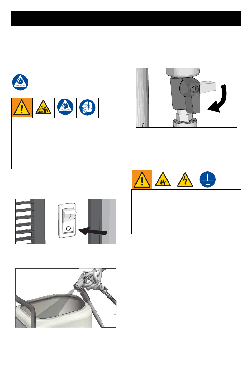
Preparation
Pressure Relief Procedure
Follow the Pressure Relief
Procedure whenever you see this
symbol.
This equipment stays pressurized until
pressure is manually relieved. To help
prevent serious injury from pressurized
fluid or splashed fluid follow the Pressure
Relief Procedure whenever sprayer is
stopped and before sprayer is cleaned or
checked, and before equipment is
serviced.
1. Turn ON/OFF switch to the OFF
position. Wait 7 seconds for power to
dissipate.
3. Open air control valve.
4. On the RTX2000pi, open gun prime
valve.
Grounding
The equipment must be grounded to
reduce the risk of static sparking and
electric shock. An electric or static spark
can cause fumes to ignite or explode. An
improper ground can cause electric shock.
A good ground provides an escape wire for
the electric current.
ti27340a
2. On the RTX1400si, trigger gun into
material hopper.
This sprayer includes a ground wire with an
appropriate ground contact. The plug must
be plugged into an outlet that is properly
installed and grounded in accordance with all
local codes and ordinances.
Do not modify the plug provided; if it does not
fit the outlet, have the proper outlet installed
by a qualified electrician.
Power Requirements
100-120V units require 100-120 VAC, 50/60
Hz, 12 or
15A, 1 phase.
Extension Cords
Use an extension cord with an undamaged
ground contact. If an extension cord is
necessary, use a 3-wire, 12 AWG (2.5 mm2)
minimum.
3A3258D 9
Page 10

Preparation
NOTE: Lighter gauge or longer extension
cords may reduce sprayer performance.
Auxiliary Air Compressor
Do not use an auxiliary air compressor with
this spray system.
Generator Requirements
3500 W (3.5 kW) minimum.
Hose Size and Length
The system comes with a 25 ft (7.6m) hose
set consisting of a 3/4 in. ID RTX1400si/1 in.
ID RTX2000pi material hose and a 3/8 in-ID
air hose.
Do not use more than 25 ft (7.6 m) of material
hose.
Soft Start/Smart Start™ System (RTX2000pi only)
“Smart” vs. “Soft”
“Smart” refers to the function where the
•
motor starts and stops when the trigger
is pulled and released. This keeps the
sprayer at full operating pressure and
allows the sprayer to spray immediately
when the gun is triggered.
• “Soft” refers to the function where the
sprayer slowly starts the pump. This
prevents a large “splotch” of material
from being discharged from the gun
when trigger is pulled after the sprayer
has sat idle for a period of time.
Smart Start
The Smart Start System is controlled by
compressed air in the tanks and lines. When
gun is triggered, air flows through the lines
and opens a flow switch. There is also
another pressure switch that senses when
the compressed air system is at operating
pressure. This second pressure switch
allows the sprayer to start immediately when
the sprayer is turned ON charging the
compressed air system to full pressure. This
method keeps the compressed air system at
operating pressure if there is a small air leak
in the system.
Soft Start
The Soft Start System is controlled by motor
power and an air cylinder. When pressurized,
the air cylinder pushes the rollers into the
peristaltic pump pushing material through the
pump. When the motor shuts off, a solenoid
valve relieves the pressure in the air cylinder
causing the rollers to disengage from the
peristaltic pump. When the motor starts again
there is a time delay while the air cylinders
charge and move the rollers into the pump
this is the “Soft Start”.
10 3A3258D
Page 11
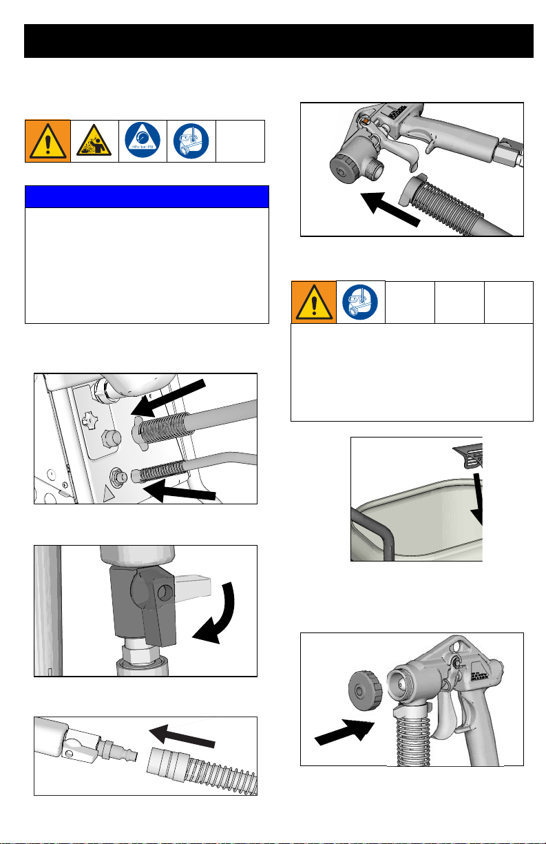
Setup
ti27341a
ti27343a
ti27344a
Setup
NOTICE
•
Do not store sprayer under pressure.
• Do not allow material to dry inside
pump, hoses, gun or spray system.
• When operating a RTX1400SI and you
are going to stop spraying for more than
five minutes turn sprayer OFF to
prevent shortened pump life.
1. Connect air hose and material hose to
sprayer air and material hose outlets.
4. Connect material hose to gun.
5. Make sure burp guard is installed.
Before adding material to the hopper,
install the burp guard. When only a small
amount of material remains in the hopper,
the burp guard prevents material from
shooting out when the unit is turned off.
This material could splash in the operator’s
eyes or on skin, or into the air.
ti27342a
2. Open air valve.
6. Install spray nozzle or wide spray disc.
See Recommended Nozzle Selection
Charts, page 15.
3. Connect air hose to gun.
ti27345a
3A3258D 11
Page 12
Setup
ti27346a
ti27383a
ti27381a
ti27382a
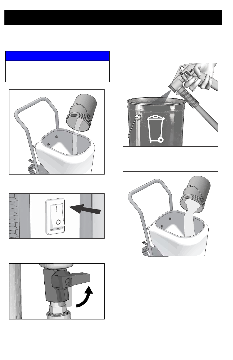
7. Pour one gallon (four liters) of water into
the material hopper.
NOTICE
To prevent pump damage, before adding
material or starting unit in cold weather, run
warm water through the pump.
8. Turn ON/OFF switch to ON position.
10. Point gun into waste bucket and pull
trigger to pump water through the
system. Continue to trigger gun until
material hopper is empty.
11. Add pre-mixed texture mix to material
hopper. See Mixing Material, page 13.
ti27380a
9. Close gun air valve. On the RTX2000pi
open the prime valve on the gun.
12. Continue to trigger gun and spray into
waste bucket until a steady stream of
material sprays out of gun.
13. Release trigger.
IMPORTANT! Fluid/air flow will be restricted
if the material/air hoses are restricted or
kinked.
12 3A3258D
Page 13

Mixing Material
ti2496b
40 lb.
TEXTURE MIX
5 GAL
PREMIX
5
GAL
ti2493b
NOTE: Correct material mixture is essential.
The pump will not operate if the mixture is too
thick.
• Mix the material in a separate container
before pouring it into hopper.
• Use Material Thickness Gauge to
determine if mixture is thin enough to
spray.
• The Material Thickness Gauge will only
determine if the material is thin enough
to pass through the pump. For some
applications or for higher speed
spraying, your mixture may need to be
thinner.
• For best results, do not use partial bags
of material.
1. Mix the material and water in a
separate container.
Dry Mix - 40 lb (18 kg) bag
Carefully mix texture material and water
according to manufacturer instructions
on bag.
Mixing Material
2. Agitate to mix, using a half-inch, variable
speed drill with mixing paddle, to a
smooth, lump-free consistency.
ti2497b
3. Allow ceiling texture to set for at least 15
minutes. Then remix prior to use.
4. After texture material is thoroughly
mixed, gently set ball end of Material
Thickness Gauge on surface of mixture.
Premix
Slowly add approximately 2 to 4 quarts
(1.9 to 3.8 liters) of water to a 5 gallon
(18.9 liter) bucket of premix.
3A3258D 13
Page 14

Mixing Material
ti2498b
READY
ADD
WATER
NOTE: For an accurate test, be sure gauge is
completely dry and clean every time it is
used.
5. Observe the ball on the material. When
the material is thin enough to spray the
ball will sink completely into the mixture
within 10 seconds.
6. If the ball does not sink completely into
the mixture within 10 seconds, add more
water, agitate and try test again.
7. Once material is mixed pour material into
the sprayer hopper. See Operation,
page 15 for nozzle selection and sprayer
adjustments.
14 3A3258D
Page 15
Operation
Operation
Texture Spraying
Recommended Nozzle Selection Charts
RTX1400si
Application Nozzle Size2Air Volume
Simulated
Acoustic
Orange peel 4 mm, beige,
1
Control air volume with gun air valve.
6 mm, white
(fine to medium)
8 mm, gray
(coarse)
6 mm, white
medium to high Splatter coat 6 mm, white
medium to high Knockdown 6 mm, white
1
Application Nozzle Size2Air Volume
low to medium
8 mm, gray
8 mm, gray
12 mm, black
2
For more material volume try a larger nozzle.
RTX2000pi
Application WideTex™ Disc Nozzle (mm) Air Volume
Standard Hardened
Simulated Acoustic - Fine W6 W6H 4high
- Medium W8 W8H 6high
- Course W10 W10H 8- 10 high
Fog W4 W4H 3high
Orange peel W4 or W6 W4H or W6H 3 - 8 medium to high
Splatter coat W6 or W8 W6H or W8H 6 - 10 low to medium
Knockdown W6 or W8 W6H or W8H 6 - 8 low
1
low
Adjusting the System
Sufficient fluid output (volume and pressure)
and good atomization are a balance of
atomizing air, material thickness/material
flow and nozzle selection. Achieving the
correct balance for your application requires
experimentation to achieve desired results.
Keep in mind these important points when
adjusting gun:
• Select proper nozzle for your
application. See Nozzle Selection
Chart. Remember, the larger the
nozzle, the heavier the pattern.
3A3258D 15
• Start sprayer with gun air flow valve
completely open. Trigger sprayer gun.
If needed, slowly close gun air flow until
you get a good spray pattern. Use minimum amount of air at spray gun to
achieve proper spray pattern and to
minimize bounce back.
+ Test spray pattern on cardboard.
Hold gun 18 to 24 in. (45.7 to 61 cm)
from surface. Use this spraying distance for most applications.
• Air and material flow adjustments are
made at the gun on all units.
+ Opening air valve increases air flow
through gun, which decreases texture
material flow through pump.
Page 16

Operation
+ Closing air valve decreases air flow
through gun, which increases texture
material flow through pump.
To achieve uniform spray pattern, adjust air
valve and flow adjustment nut on gun. If you
do not achieve the desired pattern, change
nozzles, see Recommended Nozzle
Selection Charts, page 15.
To Get Less Material
Try one or a combination of these methods:
• Open air valve.
• Turn gun flow adjustment nut
counter-clockwise to decrease flow.
• Use smaller nozzle.
To Get More Material
Try any one or a combination of these
methods:
• Close air valve.
• Turn gun flow adjustment nut clockwise
to increase flow.
• Use thinner material mixture.
• Use a larger nozzle.
For Continuous Spraying
Use trigger lock to hold trigger open and
reduce fatigue.
Check Material Consistency
Periodically
Check and thin material as needed to
maintain proper consistency. The material
may thicken as it sits and slow down
production. Agitate periodically.
Preventing Material Surge at Gun
Trigger (RTX1400si only)
Pressure will build up in the system when you
stop triggering the gun. To prevent material
surge at initial gun triggering:
• Point gun away from surface you are
spraying when you first pull trigger.
• When you first start to spray, hold the
gun away from the surface and gradually
work your way closer to it.
• Keep gun moving.
• After you begin spraying, trigger the gun
as little as possible.
Soft Start/Smart Start Operation
RTX2000pi
Smart Start
Sprayer will start under the following
conditions:
• A new sprayer is plugged in and ON/OFF
switch is turned ON.
• Gun is triggered and air valve is open far
enough.
• There is a small leak in the system and
the pressure drops below the pressure
switch setting. This may appear to be
random operation.
• When a bleeder gun is used.
• When there is no gun or hose connected
to the sprayer.
• When the pressure is relieved by
triggering the gun while the sprayer is
OFF and then turned back ON.
• Prime valve is opened.
• There is a hose failure (leak) in the twin
line hose.
Soft Start
•
The easiest way to tell if the Soft Start
System is functional is to spray material.
• The system is operating properly when a
small amount of material initially comes
out of the gun when triggered and the
volume of material slowly increases to
full spray.
NOTE: Motor runs when gun is triggered.
Sprayer is designed to stop pumping when
gun trigger is released.
16 3A3258D
Page 17

Shutdown and Cleanup
ti27341a
ti27383a
ti27381a
ti27346a
Shutdown and Cleanup
NOTE: Keep pump and hose clean when
switching between simulated acoustic,
knockdown and orange peel applications. A
dirty pump can release particles of texture
into the finish.
• To increase pump life, life turn power
OFF when not spraying.
• Before removing material hose, perform
Pressure Relief Procedure, page 9.
Make certain there is no material in the
hose.
• To keep sprayer in good operating
condition, always clean it throughly and
prepare it properly for storage.
When you have finished spraying:
1. Open gun air valve.
4. Trigger gun into bucket until most of
texture mix is pumped out.
5. Fill material hopper with 2-4 gallons of
clean water.
2. Turn ON/OFF switch to ON position.
ti27380a
3. Close gun air valve.
3A3258D 17
Page 18

Shutdown and Cleanup
ti27339a
ti27381a
ti27386a
6. Spray inside material hopper to circulate
water through gun and hose. While
circulating water, use gun to clean
material hopper.
ti27340a
10. Open gun air valve. Perform pressure
relief procedure, Pressure Relief
Procedure, page 9.
7. Partially open gun air valve to use air to
achieve better cleaning results.
ti27385a
8. Spray water into a waste bucket to empty
material hopper.
Air hose fittings can get hot. Allow sprayer
to cool down 15 minutes before removing
air hose.
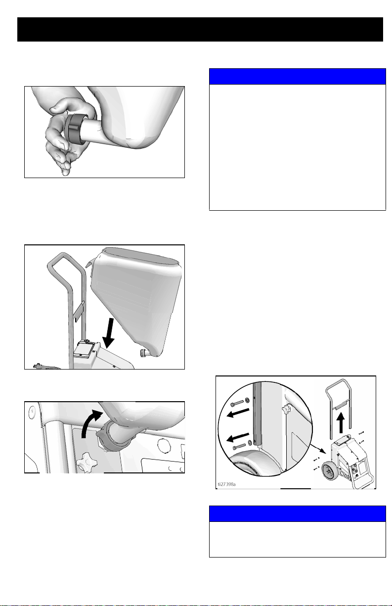
Clean Material Hopper
Material hopper can be removed for easy
cleaning.
1. Loosen bottom fitting
2. Lift material hopper straight up, off the
unit.
NOTE: A soft brush can be used to loosen
dried on material.
9. Turn ON/OFF switch to OFF position.
ti27387a
18 3A3258D
Page 19
3. Plug opening on bottom of material
ti27388a
ti27390a
ti27398a
hopper with your hand.
4. Take hopper to cleaning area for
cleaning.
5. After cleaning material hopper, position
it on sprayer handle first.
ti27389a
6. Hand tighten fitting.
Shutdown and Cleanup
NOTICE
Water or material remaining in unit when
temperatures are below freez in g can
damage motor and/or delay pump startup.
Do not allow unit to freeze.
To ensure water and material are completely drained out of unit:
1. Remove material hose from sprayer.
2. Remove pump hose from sprayer.
Empty hose and reinstall.
3. Remove hopper and drain.
Transporting Sprayer
The handle and hopper can be removed from
the sprayer for storage or transporting.
NOTE: The handle on the RTX2000pi has
semi-permanent screws. It is not
recommended that the handle be removed.
1. Remove hopper see Clean Material
Hopper, page 18.
2. Loosen screws on either side of handle.
3. Spread handle apart and remove.
NOTICE
Do not lift sprayer by the handle. To prevent
sprayer damage, handle should only be used
to push or pull the sprayer.
3A3258D 19
Page 20

Maintenance
Maintenance
Routine maintenance is important to ensure proper operation of your sprayer. Maintenance
includes performing routine actions which keep your sprayer in operation and prevent trouble
in the future.
Activity Interval
Inspect motor shield vents for blockage.
Check sprayer stall (RTX2000pi only).
With sprayer gun NOT triggered, sprayer motor should stall
and not restart until gun is triggered again.
If sprayer starts again with gun NOT triggered, inspect pump
for internal/external leaks and check prime valve for leaks.
Protect the internal drive parts of this sprayer from water. Openings in shields allow cooling of
mechanical parts and electronics inside. If water gets into these openings, the sprayer could malfunction or be permanently damaged.
Daily or each time you spray
Every 1000 gallons (3785
liters)
Texture Hoses
Check hose for damage every time you
spray. Do not attempt to repair hose if hose
jacket or fittings are damaged. Do not use
hoses shorter than 25 ft (7.6 m).
Tips
• Always clean tips with a soft brush after
spraying.
• Tips may require replacement
depending on abrasiveness of texture.
20 3A3258D
Page 21
Troubleshooting
Troubleshooting
1. Follow Pressure Relief Procedure,
page 9, before checking or repairing.
Problem Cause Solution
Sprayer won’t run Power switch not on Turn switch on.
No power at wall outlet Check outlet by plugging in
Wrong size generator Use a 3500 watt or larger gen-
Circuit breaker tripped Reset breaker.
Pump won’t pump material Air lock Open air valve on gun.
Mix too thick Add water to thin material. Use
Loose fittings Check and retighten all fittings.
Plugged gun Perform Pressure Relief Pro-
Pump hose worn out Replace hose. Recommended
Pump cold Move pump to warm room and
Material flow turned down Turn up material flow control.
Material runs out of bottom of
sprayer
Pump hose worn out Replace hose.
Loose fittings Check and retighten all fittings.
2. Check all possible problems and causes
before disassembling the unit.
another appliance. If appliance does not work, try
another outlet.
erator. Refer to Generator
Requirements, page 10.
Material Thickness Gauge.
cedure, page 9. Remove gun
from hose. Clean gun.
hose replacement - once every
year.
allow it to warm up or run hot
water through sprayer.
3A3258D 21
Page 22

Troubleshooting
Problem Cause Solution
No air from compressor Gun air valve closed Open gun air valve.
Low voltage Check extension cord length
Gun needle plugged Clean needle and retry.
Worn compressor Replace compressor. Contact
Lines not connected Check all quick disconnect
Damaged hose. Replace hose.
Speed of application slow or
slower
Intermittent flow/sputtering Hopper connection not tight Check gasket. TIghten con-
Quick disconnect does not stay
connected.
Gun will not shut off Worn nozzle or needle. Perform Pressure Relief Pro-
Fluid leaking at Flow Adjustment Nut
Needle adjustment won’t
adjust
Material too thick Thin material.
Nozzle too small Change nozzles to a larger
Too much air being used. Partially close gun air valve to
Pump hose worn Replace hose.
Plugged or dirty gun Perform Pressure Relief Pro-
Kinked hose Unkink hose.
Gun adjustment set too low Increase flow adjustment with
Too many items on same circuit
Extension cord too long or
wrong gauge
Debris in system Clean system.
Dirty or corroded fitting Clean thoroughly. Soak in oil.
Debris in needle passage Perform Pressure Relief Pro-
Damaged seal. Perform Pressure Relief Pro-
Dirty threads Clean threads.
Nozzle not on gun Put nozzle on gun.
and gauge. Replace if different than recommended. Refer
to Grounding and Electrical
Requirements, page 9.
a qualified Graco Service Center.
connections to gun and hoses.
size. See Recommended Nozzle Selection Chart, page 15.
reduce air flow.
cedure, page 9. Clean gun.
flow adjustment nut.
Unplug other items from circuit.
Use a different extension cord.
Refer to Grounding and Electric Requirements, page 9.
nection.
Apply a few drops of light oil.
cedure, page 9. Replace worn
parts.
cedure, page 9. Clean.
cedure, page 9. Replace seal.
22 3A3258D
Page 23
Troubleshooting
Problem Cause Solution
Power switch is on and sprayer
is plugged in, but motor does
not run, and pump does not
cycle.
Sprayer continues to run when
gun trigger is released.
Sprayer does not start when
gun is triggered.
Air valve on gun is closed or
not open enough.
Motor or control is damaged. Take sprayer to Graco
Electric outlet is not providing
power.
Extension cord is damaged. Replace extension cord. See
Sprayer electric cord is
damaged.
Material and/or water is frozen
or hardened in pump.
Prime valve is plugged
(RTX2000pi).
Gun is plugged. Disassemble and clean gun.
Pressure switch is damaged. Replace pressure switch.
Compressed air system leak. Locate leak; check gun, twin
Flow switch is stuck. Replace flow switch.
Flow switch is stuck. Replace flow switch.
Open air valve.
authorized service center.
Try a different outlet or plug in
something that you know is
working to test outlet.
Reset building circuit breaker
or replace fuse.
Grounding, page 9.
Check for broken insulation or
wires. Replace electric cord if
damaged.
Unplug sprayer from outlet. If
frozen do NOT try to start
sprayer until it is completely
thawed or you may damage
the motor, control board and/or
drivetrain.
Make sure power switch is
OFF. Place sprayer in a warm
area for several hours. Then
plug in powercord and turn
sprayer ON. Slowly increase
pressure setting to see if motor
will start.
If material is hardened in
sprayer, pump or pressure
switch may need to be
replaced. Take sprayer to
Graco authorized service
center.
Remove and clean prime
valve.
line hose, or internal system.
Reseal leaky fitting or replace
hose.
3A3258D 23
Page 24

Troubleshooting
Problem Cause Solution
Sprayer cycles ON and OFF
when trigger is released.
or
Sprayer cycles ON and OFF
when gun is triggered.
Pressure switch is damaged. Replace pressure switch.
Compressed air system leak. Locate leak; check gun, twin
line hose, or internal system.
Reseal leaky fitting or replace
hose.
Flow switch is stuck. Replace flow switch.
Check valve is damaged. Replace check valve.
24 3A3258D
Page 25

RTX1400si Sprayer
Ref. Torque Ref. Torque
15-20 in-lb (1.7 - 2.3 N•m) 27-32 in-lb (3.1 - 3.6 N•m)
75-95 in-lb (8.5 - 10.7 N•m) 90-110 in-lb (10.2 - 12.4 N•m)
50-70 in-lb (5.6 - 7.9 N•m)
65-85 in-lb (7.3 - 9.6 N•m) then
back off 1/4 turn
40-50 in-lb (4.5 - 5.6 N•m)
152
6
3
8
4
8
4
1
29
21
122
29
25
42
80
80
26
34
49
27
40
19
15
36
50
3
30
30
7
5
2
43
63
31
32
31
42
12
9
14
52
57
23
59
76
10
11
47
13
42
64
70
ti29889a
79
121
124
125
6
5
2
3
8
1
5
2
4
2
See page 32.
2
8
RTX1400si Sprayer
3A3258D 25
Page 26

RTX1400si Sprayer
Ref. Torque Ref. Torque
15-20 in-lb (1.7 - 2.3 N•m) 27-32 in-lb (3.1 - 3.6 N•m)
75-95 in-lb (8.5 - 10.7 N•m) 90-110 in-lb (10.2 - 12.4 N•m)
50-70 in-lb (5.6 - 7.9 N•m)
65-85 in-lb (7.3 - 9.6 N•m) then
back off 1/4 turn
40-50 in-lb (4.5 - 5.7 N•m)
15263
8
4
21
16
4
54
6
29
80
80
60
26
38
35
27
19
65
66
3
68
69
55
93
77
51
ti27872a
61
78
5
8
2
See page 32.
RTX1400si Sprayer (cont’d)
26 3A3258D
Page 27

RTX1400si Sprayer Parts List
RTX1400si Sprayer
Ref. Part Description
1 17H407 FRAME, front 1
2 15J600 BOX, tool 1
3 15H069 SUPPORT, hopper 1
4 17H404 FRAME, back 1
5 17K497 SHIELD 1
6 277319 SHIELD, bottom 1
7 15J672 SHIELD, left, painted 1
8 15J671 AXLE 1
9 110755 WASHER, plain 4
10 17K546 WHEEL, 10” includes 112
11 112612 CAP, hub 2
12 17H418 HANDLE, painted 1
13
17K511 DOOR, shield 1
14 102313 SCREW, cap, hex 4
15 288336
16
288623 HOSE, coupled 1
19 12066 0 SWITCH, rocker 1
21 15H910 BRACKET, pump 1
22 15C090 GAUGE, thickness,
23 24S107
25 17H410 PLATE, hose 1
26 105240 SCREW, cap, hex, hd 1
27 113981 NUT, lock 1
29 117630 SCREW, Torx 6
30 117633 SCREW, slot, hex 3
31 120771 SCREW, mach, pnhd
32 17H490 PAD, isolator 1
35 120236 SCREW, shoulder 1
36 120731 WASHER, flat, thin 1
38 289591 CYLINDER, air, assy. 1
40 16M501 CORD, power 1
42 15J862 KNOB 3
43 15D561 COVER, tool tray 1
45 288629 GUN, spray, texture 1
46
17J454 HOSE, texture, blue 1
47 120759 PAD, non-slip, foot 1
49 115498 SCREW, mach, slot 2
FITTING, bulkhead,
assembly.
fluid
HOPPER, 10 gallon 1
Qty.
Ref. Part Description
50 104227 NUT, lock 1
51
15H841 LABEL, warning 1
52
15K616 LABEL, caution 1
54 17J928 LABEL, instructions 1
55 TUBE, air, 0.250 1
57
16M768 LABEL, warning 1
59 17H63 8 BAFFLE, hopper 1
60 TUBE, air, 0.250 1
61 TUBE, air, 0.375 1
63 11183 1 SCREW, skt, button 1
64 102040 NUT, hex, lock
65 115244 NUT, regulator 1
66 117694 KIT, regulator, air 1
68 11772 0 GAUGE, pressure
69 120653 FITTING, push to con-
1
70 120444 SCREW, mach, pnhd 1
76 LABEL, hopper, RTX
17H625 Model 17H572 1
1
5
17P190 Model 17P189 1
77 17H522 LABEL, control 1
78 246013 KIT, meter hour, Model
79 17H627 LABEL, side RTX 1
80 120215 WASHER, Belleville 2
93 TUBE, air, 0.250 1
121 17L030 LABEL 1
122 17L120 GROMMET, edge 1
124 15E332 LABEL, Home Depot
125 17P191 LABEL, material mix-
17L017 KIT, tube, air includes
Replacement Danger and Warning labels,
tags, and cards are available at no cost.
includes 69
nect
17P189
Tool Rental
ing, Model 17P189
55, 60, 61, 93
Qty.
1
1
1
2
1
1
3A3258D 27
Page 28

RTX2000pi Sprayer
Ref. Torque Ref. Torque
15-20 in-lb (1.7 - 2.3 N•m) 27-32 in-lb (3.1 - 3.6 N•m)
75-95 in-lb (8.5 - 10.7 N•m) 90-110 in-lb (10.2 - 12.4 N•m)
50-70 in-lb (5.6 - 7.9 N•m)
65-85 in-lb (7.3 - 9.6 N•m) then
back off 1/4 turn
40-50 in-lb (4.5 - 5.7 N•m)
152
6
3
8
4
8
1
29
21
29
25
42
80
80
26
27
40
49
36
50
3
30
30
7
5
2
43
63
31
31
42
32
12
74
9
14
11
23
56
37
62
87
104
121
89
90
44
48
15
33
44
47
28
73
67
52
76
57
105
103
59
13
42
64
70
20
86
10
ti29890a
122
79
124
125
See page 32.
6
5
2
3
8
8
2
2
2
1
1
2
4
5
RTX2000pi Sprayer
28 3A3258D
Page 29

RTX2000pi Sprayer (cont’d)
Ref. Torque Ref. Torque
15-20 in-lb (1.7 - 2.3 N•m) 90-110 in-lb (10.2 - 12.4 N•m)
75-95 in-lb (8.5 - 10.7 N•m)
9-11 in-lb (1- 1.2 N•m)
50-70 in-lb (5.6 - 7.9 N•m)
65-85 in-lb (7.3 - 9.6 N•m) then
back off 1/4 turn
40-50 in-lb (4.5 - 5.7 N•m) 120-130 in-lb (13.6 - 14.7 N•m)
27-32 in-lb (3.1 - 3.6 N•m)
16273
8
4
9
5
21
4
6
29
80
80
26
16
38
35
27
49
19
88
65
3
68
69
56
62
100
66
96
92
106
91
106
98
108
97
53
55
67
81
51
77
54
101
102
41
ti27870a
93
37
99
100
53
58
109
122
118
123
78
2
8
9
5
8
5
7
1
See page 32.
2
5
1
RTX2000pi Sprayer
73
3A3258D 29
107
Page 30

RTX2000pi Sprayer
RTX2000pi Sprayer Parts List
Ref. Part Description Qty.
1 17H407 FRAME, front 1
2 15J600 BOX, tool 1
3 15H069 SUPPORT, hopper 1
4 17H404 FRAME, back 1
5 17K497 SHIELD, right 1
6 277319 SHIELD, bottom 1
7 15J672 SHIELD, left 1
8 17H429 AXLE 1
9 110755 WASHER, plain 4
10 17K531 WHEEL, pneumatic 2
11 112612 CAP, hub 2
12 17H418 HANDLE, painted 1
13 17K511 DOOR, shield 1
14 102313 SCREW, cap, hex 4
15 288336
288623 HOSE, coupled 1
16
19 120660 SWITCH, rocker 1
20 17K530 SPACER, wheel 2
21 15H910 BRACKET, pump 1
22 15C090 GAUGE, thickness, fluid 1
23 24S108
25 17H410 PLATE, hose 1
26 105240 SCREW, cap, hex, hd 1
27 113981 NUT, lock 1
28 120411
29 117630 SCREW, Torx 6
30 117633 SCREW, slot, hex 3
31 120771 SCREW, mach, pnhd
32 17H490 PAD, isolator 1
33 24Z003
35 120236 SCREW, shoulder 1
36 120731 WASHER, flat, thin 1
37 17K594
38 289591 CYLINDER, air, assy. 1
40 16M501 CORD, power 1
41 101501 SCREW, mach
42 15J862 KNOB 3
43 15D561 COVER, tool tray 1
44 115942 NUT, hex, flange head 3
45 24S134 GUN, spray, texture 1
17J420 HOSE, texture, 2line 1
46
47 17J201 BUMPER, recessed 2
48 16F710 CONNECTOR, 3/8 1
49 115498 SCREW, mach, slot 2
50 104227 NUT, lock 1
15H841 LABEL, warning 1
51
15K616 LABEL, caution 1
52
53 TUBE, air, 0.250 2
FITTING, bulkhead 1
HOPPER, 13 gallon 1
RIVOT, blind 2
ADAPTER, swivel
KIT, repair, flow switch
includes 41, 44, 53, 56,
118, 123
5
1
1
Ref. Part Description Qty.
54 17H629 LABEL, instructions 1
55 TUBE, air, 0.250 1
56 120830 CLAMP, loop 1
16M768 LABEL, wa rning 1
57
58 121141 FITTING, elbow, swivel 1
59 17H638 BAFFLE, hopper 1
62 17K597
63 111831 SCREW, skt, button 1
64 102040 NUT, hex, lock 1
65 115244 NUT, regulator 1
66 117694 KIT, regulator, air 1
67 17K598 KIT, repair, circuit board
68 117720 GAUGE, pressure,
69 120653
70 120444 SCREW, mach, pnhd 1
73 120743 SCREW, mach, pnhd 4
74 121092
76 LABEL, hopper, RTX
17J506 Model 17H573 1
17H626 Model 17H574, 17K301 1
77 17H522 LABEL, control 1
78 246013 KIT, meter hour, Model
79 17H627 LABEL, side RTX 1
80 120215 WASHER, Belleville 2
81 17J525 SCREW, mach, slot 2
86 17K529 WASHER, plain, wide 2
87 17K593 KIT, repair, accumulator
88 TUBE, air, 0.250 1
89 121150 FITTING, elbow 1
90 100124 NIPPLE, pipe 1
91 116504 FITTING, tee 1
92 17K595
93 TUBE, air, 0.250 1
96 128051 CLAMP, loop 1
97 17K596 KIT, repair, pressure
98 117317 SCREW, plastite 2
99 TUBE, air, 0.375 1
100 TUBE, air, 0.375 2
101 17J638 BRACKET, mounting 1
102 118444
103 17J933 LABEL, smart start 1
KIT, repair, solenoid valve
includes 81
includes 73, 101, 102
includes 69
FITTING, push to connect
CLIP, spring, Model
17H574
, 17K301
17H574, 17K301
tank includes 44, 48, 89,
90, 103, 104
KIT, repair, check valve
includes 58, 91, 96, 106,
107, 108
switch includes 53, 98, 118
SCREW, mach, slot, hex
1
1
1
1
1
1
1
1
1
4
30 3A3258D
Page 31

Ref. Part Description Qty.
104 100403 PLUG, pi pe 1
105 110198 COUPLER, li ne, air 1
106 17J393 FITTING, tube, straight 2
107 111800 SCREW, c ap hex, hd 1
108 110996 NUT, hex, flange head 1
109 TUBE, air, 0.375 2
118 102478 STRAP, tie 2
119 TUBE, air 1
121 17L028 LABEL, pi models 1
122 17L120 GROMMET, edge 1
123 17L386 FITTING 1
124 15E332 LABEL, Home Depot Tool
Rental
125 17P192 LABEL, material mixing,
Model 17K301
RTX2000pi Sprayer
2
1
17L017 KIT, tube, air includes 53,
55, 88, 93, 99, 100, 109,
119
Replacement Danger and Warning labels,
tags, and cards are available at no cost.
1
3A3258D 31
Page 32

Compressor Parts
Ref. Torque Ref. Torque
18-22 ft-lb (24.4 - 29.8 N•m) 50-65 in-lb (5.7 - 7.3 N•m)
190-230 in-lb (21.5 - 26 N•m)
120-140 in-lb (13.6 - 15.8 N•m) Finger tighten
cap screw in position 4 first then torque cap
screws in the sequence illustrated.
Piston retaining bolt & crankshaft bolts must
torqued before head bolts (30) are torqued.
Hand tighten, then 1 full turn
60-72 in-lb (6.8 - 8.1 N•m)
1
5
26384
ti27402a
17
3
13
20
42
41
10
44
40
30
4
29
5
27
28
6
20
17
31
32
26
7
20
14
38
46
45
9
2
1
43
19
39
8
10
11
19
2
1
4
3
2
1
4
4
1
3
8
Torque Sequence
5
6
6
Compressor Parts
32 3A3258D
Page 33

Compressor Parts List
Part Description
Ref.
24S128 KIT, repair, compressor,
24S129 KIT, repair, compressor,
1 17K879 KIT, repair, motor, uni-
2 120466 FAN, motor
3 288616 PULLEY, with rollers
4 24S130 KIT, repair, head, com-
5 24S131 KIT, repair, plate, valve
6 17H553 CYLINDER, compressor
7 24S132 KIT, repair, piston/cylin-
8 120617 VALVE, pressure relief
9 24S133 KIT, repair, cooler
complete
rebuild incl udes 4, 5, 6, 7,
14, 17, 20, 26, 28, 29, 30,
40
versal, 120V includes 2,
14, 45, 46
includes 13, 17
pressor includes 5, 28,
29
der includes 5, 6, 17, 20,
28, 29
includes 27
Qty.
Compressor Parts
Part Description
Ref.
10 120603 FITTING, cartridge
11 120602 FITTING, cartridge
13 120234 BELT, 3mm, timing
14 120233 BELT, 3mm, timing
17 120204 SCREW, mach, hex
19 114548 BEARING, bronze
1
20 120227 BEARING, ball
26 17H525 SPACER, compressor
30
1
1
1
1
1
1
1
1
17H560 SCREW, cap serrated
flange head
31 119872 SCREW, shoulder
32 120659 WASHER, flat
38 288611 KIT, repair, idler includes
14, 39
39 C20021 SCREW, cap, skt head
40 17H657 FILTER, intake muffler
41 15H978 FRAME, pump mount
42 15H077 SHAFT, transfer
43 15H076 PULLEY, drive
44 15G817 PULLEY, pump
45 260215 SCREW, hex head
46 100023 WASHER, flat
Qty.
2
1
1
1
2
2
3
4
4
1
1
1
1
1
1
1
1
1
2
2
3A3258D 33
Page 34

Wiring Diagram
WHITE
GREEN
POWER CORD
SWITCH
HOUR METER
MOTOR
GREEN
BLACK
BLACK
ti27930b
WHITE
WHITE
GREEN
GREEN
49 REF
11
TRIAC IS PART OF
PC BOARD ASSEMBLY
BLACK
BLACK
VIOLET
VIOLET
ORANGE
ORANGE
GRAY
VIOLET
MOTOR
HOUR
METER
AC NEUTRAL
AC HOT
TRIAC
GATE
TRIAC
A1
MOTOR
SOLENOID
PRIME
SWITCH
PRESSURE
SWITCH
FLOW
SWITCH
BROWN WHITE
BLACK
BLACK
RED VIOLET VIOLET VIOLET
GRAY ORANGE ORANGE ORANGE
BLUE
Wiring Diagram
RTX1400si
Hour meter on 17P189 models only.
RTX2000pi
YELLOW
BROWNBLUE
ti27929a
Hour meter on 17H574 models only.
34 3A3258D
RED
Page 35
Technical Specifications
Technical Specifications
US Metric
Sprayer
Material Hopper Capacity
RTX1400si
RTX2000pi
Maximum Delivery with Texture
RTX1400si
RTX2000pi
Maximum Fluid Working Pressure 70 psi 4.8 bar, 0.48 MPa
Maximum Air Working Pressure 45 psi 3.1 bar, 0.31 MPa
Compressor Air Displacement 6.1 cfm @ 20psi 17.3 l/m @ 1.4 bar, 0.14 Mpa
Compressor Specifications Universal motor thermally protected, oil-less
Electric Motor Universal AC 15Amp 1.5 Hp
Power Cord 14 AWG, 3-wire, 25 ft
Generator Minimum 3500 W
Power Requirements
Dimensions
Height
RTX1400si
RTX2000pi
Length
RTX1400si
RTX2000pi
Width
RTX1400si
RTX2000pi
Weight (includes hose and gun)
RTX1400si
RTX2000pi
Weight (gun)
RTX1400si
RTX2000pi
Noise** (dBa) @ max air pressure)
Sound pressure
Sound power
Storage temperature range
Operating temperature range
–35° to 160°F –1.6° to 71°C
40° to 115°F 4° to 46°C
10 gal 38 l
13 gal 49 l
1.4 gpm 5.3 lpm
2.0 gpm 7.6 lpm
110–120V, 15 A, 1Ø
40.9 in. 104 cm
41.6 in. 106 cm
23.6 in. 60 cm
24.25 in. 62 cm
19.38 in. 49 cm
22.2 in. 56 cm
74.3 lb. 33.7 kg
86 lb. 39 kg
1.4 lb. 0.6 kg
2.3 lb. 1.0 kg
88.4 dBa*
102.8 dBa*
3A3258D 35
Page 36

Technical Specifications
US Metric
Materials of Construction
Wetted materials on all models brass, aluminum, plastic, stainless steel, plated carbon
steel, elastomer
Notes
* Startup pressures and displacement per cycle may vary based on suction condition,
discharge head, air pressure, and fluid type.
** Sound pressure measured 3 feet (1 meter) from equipment while spraying.
Sound power measured per ISO-9614.
Pump damage will occur if water-based fluid freezes in pump.
Damage to plastic parts may result if impact occurs in low temperature conditions.
Temperature affects material viscosity, which can affect sprayer performance.
36 3A3258D
Page 37

Graco Standard Warranty
Graco Standard Warranty
Graco warrants all equipment referenced in this document which is manufactured by Graco and bearing
its name to be free from defects in material and workmanship on the date of sale to the original purchaser
for use. With the exception of any special, extended, or limited warranty published by Graco, Graco will,
for a period of twelve months from the date of sale, repair or replace any part of the equipment
determined by Graco to be defective. This warranty applies only when the equipment is installed,
operated and maintained in accordance with Graco’s written recommendations.
This warranty does not cover, and Graco shall not be liable for general wear and tear, or any malfunction,
damage or wear caused by faulty installation, misapplication, abrasion, corrosion, inadequate or
improper maintenance, negligence, accident, tampering, or substitution of non-Graco component parts.
Nor shall Graco be liable for malfunction, damage or wear caused by the incompatibility of Graco
equipment with structures, accessories, equipment or materials not supplied by Graco, or the improper
design, manufacture, installation, operation or maintenance of structures, accessories, equipment or
materials not supplied by Graco.
This warranty is conditioned upon the prepaid return of the equipment claimed to be defective to an
authorized Graco distributor for verification of the claimed defect. If the claimed defect is verified, Graco
will repair or replace free of charge any defective parts. The equipment will be returned to the original
purchaser transportation prepaid. If inspection of the equipment does not disclose any defect in material
or workmanship, repairs will be made at a reasonable charge, which charges may include the costs of
parts, labor, and transportation.
THIS WARRANTY IS EXCLUSIVE, AND IS IN LIEU OF ANY OTHER WARRANTIES, EXPRESS OR
IMPLIED, INCLUDING BUT NOT LIMITED TO WARRANTY OF MERCHANTABILITY OR WARRANTY
OF FITNESS FOR A PARTICULAR PURPOSE.
Graco’s sole obligation and buyer’s sole remedy for any breach of warranty shall be as set forth above.
The buyer agrees that no other remedy (including, but not limited to, incidental or consequential
damages for lost profits, lost sales, injury to person or property, or any other incidental or consequential
loss) shall be available. Any action for breach of warranty must be brought within two (2) years of the
date of sale.
GRACO MAKES NO WARRANTY, AND DISCLAIMS ALL IMPLIED WARRANTIES OF
MERCHANTABILITY AND FITNESS FOR A PARTICULAR PURPOSE, IN CONNECTION WITH
ACCESSORIES, EQUIPMENT, MATERIALS OR COMPONENTS SOLD BUT NOT MANUFACTURED
BY GRACO. These items sold, but not manufactured by Graco (such as electric motors, switches, hose,
etc.), are subject to the warranty, if any, of their manufacturer. Graco will provide purchaser with
reasonable assistance in making any claim for breach of these warranties.
In no event will Graco be liable for indirect, incidental, special or consequential damages resulting from
Graco supplying equipment hereunder, or the furnishing, performance, or use of any products or other
goods sold hereto, whether due to a breach of contract, breach of warranty, the negligence of Graco, or
otherwise.
FOR GRACO CANADA CUSTOMERS
The Parties acknowledge that they have required that the present document, as well as all documents,
notices and legal proceedings entered into, given or instituted pursuant hereto or relating directly or
indirectly hereto, be drawn up in English. Les parties reconnaissent avoir convenu que la rédaction du
présente document sera en Anglais, ainsi que tous documents, avis et procédures judiciaires exécutés,
donnés ou intentés, à la suite de ou en rapport, directement ou indirectement, avec les procédures
concernées.
3A3258D 37
Page 38

Graco Information
For the latest information about Graco products, visit www.graco.com.
For patent information, see www.graco.com/patents.
TO PLACE AN ORDER, contact your Graco distributor or call 1-800-690-2894 to identify the
nearest distributor.
All written and visual data contained in this document reflects the latest product information available at
Graco reserves the right to make changes at any time without notice.
Original instructions. This manual contains English. MM 3A3258
International Offices: Belgium, China, Japan, Korea
GRACO INC. AND SUBSIDIARIES • P.O. BOX 1441 • MINNEAPOLIS MN 55440-1441 • USA
Copyright 2015, Graco Inc. All Graco manufacturing locations are registered to ISO 9001.
the time of publication.
Graco Headquarters: Minneapolis
www.graco.com
Revision D, September 2016
 Loading...