

Page 1

Repair-Parts
3A1706K
Reactor® E-30i and E-XP2i
Electric, Heated, Integrated Plural Component Proportioning System With Integrated Generator. For
spraying polyurethane foam and polyurea coatings. For professional use only. Not for use in explosive
atmospheres or hazardous locations.
Important Safety Instructions
Read all warnings and instructions in this manual.
instructions.
Save these
EN
PROVEN QUALITY. LEADING TECHNOLOGY.
Page 2

Contents
Warnings .............................................................3
Important Two-Component Material
Information .............................................7
Proportioner Models ............................................. 9
Systems............................................................. 11
Accessories........................................................12
Supplied Manuals............................................... 13
Related Manuals ................................................ 13
Troubleshooting..................................................14
Error Codes and Troubleshooting..................14
Load Center Diagnostics .............................. 37
Repair................................................................ 46
Before Beginning Repair...............................46
Pressure Relief Procedure............................ 46
Flushing...................................................... 47
Flush Inlet Strainer Screen ........................... 48
Shutdown.................................................... 49
Drain Coolant .............................................. 50
Refill Proportioner Coolant Loop ................... 51
Refill Engine Coolant Loop ........................... 52
Coolant Specifications.................................. 53
Change Pump Lubricant............................... 53
Remove Pump............................................. 54
Install Pump ................................................ 56
Repair Drive Housing...................................56
Repair Motor Brushes .................................. 59
Repair Electric Motor.................................... 61
Repair Circuit Breaker Module......................62
Replace Relays and Fuses........................... 64
Replace Transducers................................... 65
Replace Fans ..............................................66
Repair Booster Heater..................................68
Repair Heated Hose..................................... 71
Repair Fluid Temperature Sensor
(FTS)............................................. 72
Replace Heat Exchangers............................74
Replace Power Supply ................................. 77
Replace Circulation Pump ............................ 78
Repair Sight Glass Filter............................... 79
Repair Filter Housing Filter...........................80
Remove Fuel Tank....................................... 81
Replace Battery ...........................................81
Repair Fusible Link Harness......................... 82
Remove Radiator......................................... 84
Repair Advanced Display Module
(ADM) ............................................ 85
Repair Engine Control Module ......................85
Replace Motor Control Module (MCM) ........... 86
Replace High Power Temperature Control
Module (HPTCM)............................86
Replace Low Power Temperature Control
Module (LPTCM)............................86
Remove Proportioner................................... 88
Repair Engine..............................................90
12V Charge Alternator..................................90
Notes ................................................................91
Parts.................................................................. 92
Electrical Schematics........................................ 134
Repair and Spare Parts Reference .................... 149
Dimensions...................................................... 151
Technical Specifications.................................... 154
Graco Standard Warranty.................................. 158
2
3A1706K
Page 3

Warnings
Warnings
The following warnings are for the setup, use, grounding, maintenance and repair of this equipment. The
exclamation p oi nt symbol alerts you to a ge neral warning and the hazard symbol refers to procedure-s pec i fic
risks. When these symbols appea r in the body of this m anu al refer bac k to these Warnings. Product-specific
hazard symbols and warnings not covered in this section may appear throughout the body of this manual
where applicable.
WARNING
ELECTRIC SHOCK HAZARD
This equipm en t must be grounded. Improper g roundin g, setup, or u sa ge of the sys tem can
cause electric shock.
• Turn off and disconnect power at main switch before disconnecting any cables and before
servicing equipment.
• Connect only to grounded power source.
• All electrical wiring must be done by a qualified electrician and comply with all local codes
and regulations.
TOXIC FLUID OR FUMES
Toxic fluids or fumes can cause serious injury or death if splashed in the eyes or on skin,
inhaled, or swallowed.
• Read MSDS s to know the s pec ific hazards of the fluids you are using.
• Store hazardous fluid in approved containers, and dispose of it according to applicable
guidelines.
CARBON MONOXIDE HAZARD
Exhaust contains poisonous carbon monoxide, which is colorless and odorless. Breathing
carbon monoxide can cause death.
• Donotoperateinanenclosedarea.
PERSONAL PROTECTIVE EQUIPMENT
You must wear appropriate protective equipment when operating, servicing, or when in the
operating area of the equipment to help protect you from serious injury, including eye injury,
hearing loss, inhalation of toxic fumes, and burns. This equipment includes but is not limited to:
• Protective eyewear, and hearing protec tio n.
• Respirators, protective clothing, and gloves as recommended by the fluid and solvent
manufacturer.
3A1706K 3
Page 4

Warnings
WARNING
SKIN INJECTION HAZARD
High-pressure fluid from dispensing device, hose leaks, or ruptured components will pierce
skin. This may look like just a cut, but it is a serious injury that can result in amputation.
immediate surgical treatment.
• Engage trigger lock when not dispensing.
• Do not p oin t dispensing devic e at anyone or at any part of the body.
• Do not put your hand over the fluid ou tle t.
• Do not stop or deflect l eak s with your hand , body, glove, or rag .
•Followthe
checking, or servicing equipment.
• Tighten all fluid connections before operating the equipment.
• Check hoses and couplings daily. Replace worn or damaged parts immediately.
FIRE AND EXPLOSION HAZARD
Flammable fumes, such as solvent and paint fumes, in work area can ignite or explode. To help
prevent fire and explosion:
Pressure Relief Procedure
when y ou stop di spens i ng and befo re cleaning,
Get
• Use equipment only in well ventilated area.
• Do not fill fuel tank while engine is running or hot; shut off engine and let it cool. Fuel is
flammable and can ignite or explode if spilled on hot surface.
• Eliminate all ignition sources; such as pilot lights, cigarettes, portable electric lamps, and
plastic drop cloths (potential static arc).
• Keep work area free of debris, including solvent, rags and gasoline.
• Do not plug or unplug power cords, or turn light switches on or off when fl ammable fumes
are present.
• Ground all equipment in the work area. See
• Use only grounded hoses.
• Hold gun firmly to side of grounded pail when triggering into pail.
• If the re is static sparking or you feel a shock,
equipment until you identify and correct the problem.
• Keep a working fire extinguisher in the work area.
THERMAL EXPANSION HAZARD
Fluids subjected to heat in confined spaces, including hoses, can create a rapid rise in pressure
due to the thermal expansion. Over-pressurization can result in equipment rupture and serious
injury.
• Open a valve to relieve the fluid expansion during heating.
• Replace hoses proactively at regular intervals based on your operating conditions.
Grounding
stop operation immediately.
instructions.
Do not use
4
3A1706K
Page 5

Warnings
WARNING
PRESSURIZED ALUMINUM HAZARD
Use of fluids that are incompatible with aluminum in pressurized equipment can cause serious
chemical reaction and equipment rupture. Failure to follow this w arning can result in death,
serious injury, or property damage.
• Do not use 1,1,1-trichloroethane, methylene c hl orid e, other hal oge nate d hydrocarbon
solvents or fluids containing suc h solvents.
• Many other fluids may contain chemicals that can react with aluminum. Contact your material
supplier for compatibi lity .
PLASTIC PARTS CLEANING SOLVENT HAZARD
Many solvents can degrade plastic parts and cause them to fail, which could cause serious
injury or property damage.
• Use only compatible water-based solvents to clean plastic structural or pressure-containing
parts.
•See
Technical Data
solvent manufacturer’s MSDSs and recommendations.
in this and all other equipment instruction manuals. Read fluid and
EQUIPMENT MISUSE HAZARD
Misuse can cause death or serious injury.
• Do not operate the unit when fatigued or under the influence of drugs or alcohol.
• Do not exceed the maximum working pressure or temperature rating of the lowest rated
system c omp one nt. See
• Use fluids and solvents that are compatible with equipment wetted parts. See
in all equipment manuals . Read flui d and solvent manufacturer’s warnings. For complete
information about your material, request MSDS from distributor or retailer.
• Do not leave the work area while equipment is energized or under pressure. Turn off all
equipment and follow the
• Check equi pm ent daily. Repair or replace worn o r da ma ged parts i mm edi ate ly with genuine
manufacturer’s replacement parts only.
• Do not alter or modify equipment.
• Use equipment only for its intended purpose. Call your distributor for information.
• Route hoses and cables away from traffic areas, sharp edges, moving parts, and hot surfaces.
• Do not kink or over bend hoses or use hoses to pull equipme nt.
• Keep children and animals away from work area.
• Comply with all applicable safety regulations.
Technical Data
Pressure Relief Procedure
in all equipment manuals.
Technical Data
when equipment is not in use.
3A1706K 5
Page 6

Warnings
WARNING
BATTERY HAZARD
The battery may leak, explode, cause burns, or cause an explosion if mishandled.
• Only use the battery type specified for use with the equipment. See
• Battery maintenance must only be performed or supervised by personnel knowledgeable of
batteries and the required precautions. Keep unauthorized personnel away from battery.
• When replacing the battery, use the same lead-acid automotive battery, with 800 CCA
minimum, specified for use with the equipment. See
• Do not dispose of battery in fire. The battery is capable of exploding.
• Follow local ordinances and/or regulations for disposal.
• Do not op en or mu til ate the battery. Rel eas ed electrolyte has bee n known to be harmfu l to
the skin and eyes and to be toxic.
• Remove watches, rings, or other metal objects.
• Only use tools with insulated handles. Do not lay tools or metal parts on top of battery.
MOVING PARTS HAZARD
Moving parts can pinch, cut or amputate fingers and other body parts.
• Keep clear of moving parts.
• Do not operate equipment with protective g uards or covers removed.
• Pressurized equipment can start without warning. B efore checking, moving, or servicing
equipment, follow the
ENTAGLEMENT HAZARD
Rotating parts can cause serious inj ury.
• Keep clear of moving parts.
• Do not operate equipment with protective g uards or covers removed.
• Do not wear loose clothing, jewelry or long hair while operating equipment.
• Equipment can start without warning. Before checking, moving, or servicing equipment,
follow the
Pressure Relief Procedure
Pressure Relief Procedure
and disconnect all power sources.
Technical Data
and disconnect all power sources.
Technical Data
.
.
BURN HAZARD
Equipment surfaces and fluid that’s heated can become very hot during operation. To avoid
severe burns:
• Do not touch hot fluid or equipmen t.
6 3A1706K
Page 7
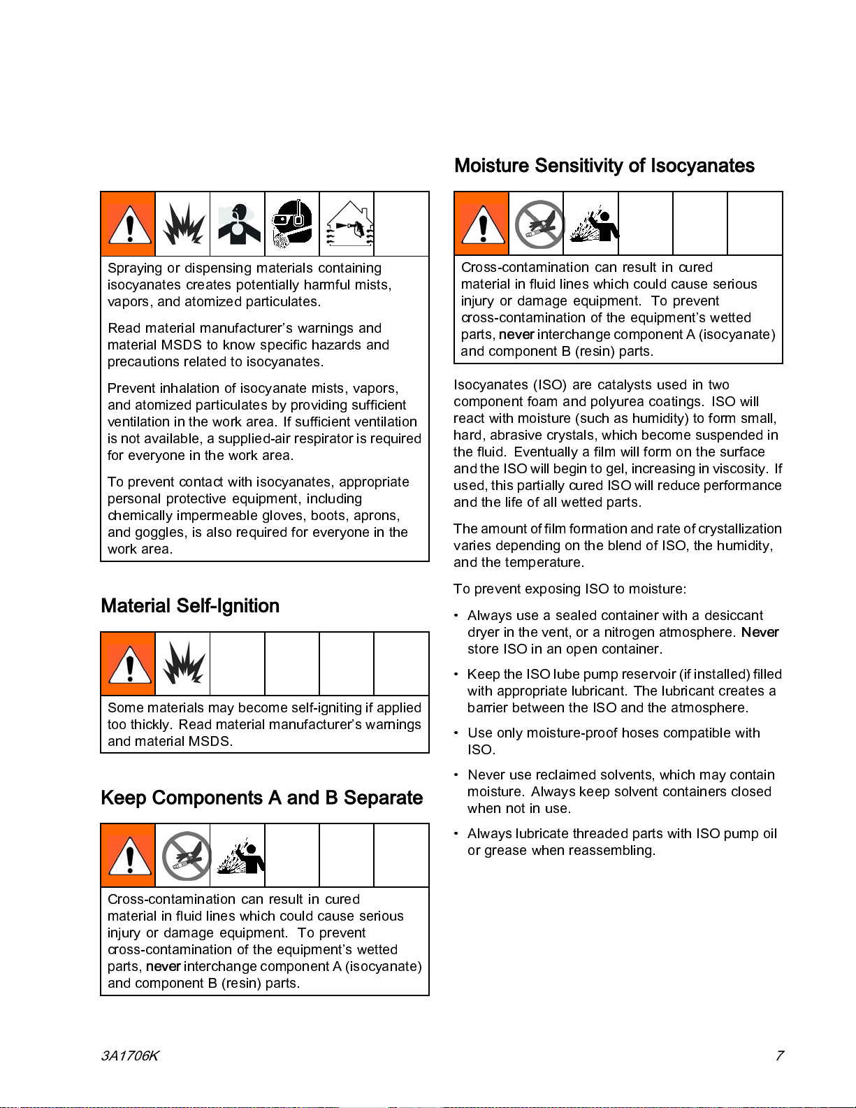
Important Two-Component Material Information
Important Two-Component Material Information
Isocyanate Conditions
Spraying or dispensing materials containing
isocyanates creates potentially harmful mists,
vapors, and atomized particulates.
Read material manufacturer’s warnings and
material MSDS to know specific hazards and
precautions rel ate d to isocyanates.
Prevent i nh ala tio n of isocy ana te mists, vapors,
and atomized particulates by providing sufficient
ventilation in the work area. If sufficient ventilation
is not available, a supplied-air respirator is required
for everyone in the work area.
To prevent contact with isocyanates, appropriate
personal protective equipment, including
chemically impermeable gloves, boots, aprons,
and goggles , is also requi red for everyone in the
work area.
Moisture Sensitivity of Isocyanates
Cross-contamination can result in cured
material in fluid lines which could cause serious
injury or damage equipment. To prevent
cross-contamination of the equipment’s wetted
parts,
never
interchange component A (is ocyanate)
and component B (resin) parts.
Isocyanates (ISO) are catalysts used in two
component foam and polyurea coatings. ISO will
react with moisture (such as humidity) to form small,
hard, abrasive crystals, which become suspended in
the fluid. Eventually a film will form on the surface
and the ISO will begi n to gel, inc reas ing in viscosity. If
used, this partially cured ISO will reduce performance
and the life of all wetted parts.
The amount of film formation and rate of crystal lization
varies depending on the blend of ISO, the humidity,
and the temperature.
Material Self-Ignition
Some materials may become self-igniting if applied
too thickly. Read material manufacturer’s warnings
and material MSDS.
Keep Components A and B Separate
Cross-contamination can result in cured
material in fluid lines which could cause serious
injury or damage equipment. To prevent
cross-contamination of the equipment’s wetted
parts,
never
interchange component A (is ocyanate)
and component B (resin) parts.
To prevent exposing ISO to moisture:
• Always use a sealed container with a desiccant
dryer in the ve nt, or a nit rogen atmosphere.
store ISO in an open container.
• Keep the ISO lube pump reservoir (if installed) filled
with appropriate lubricant. The lubricant creates a
barrier between the ISO and the atmosphere.
• Use only moisture-proof hoses compatible with
ISO.
• Never use reclaimed solvents, which may contain
moisture. Always keep solvent containers closed
when not in use.
• Always lubricate threaded parts with ISO pump oil
or grease when reassembling.
Never
3A1706K
7
Page 8

Important Two-Component Material Information
Foam Resins with 245 fa Blowing Agents
Some foam blowing agents will froth at temperatures
above 90°F (33°C) when not under pressure,
especially if agitated. To reduce frothing, minimize
preheating i n a circulation system.
Changing Materials
Changing the material types used in your equipment
requires special attention to avoid equipment damage
and downtime.
• When changing materials, flush the equipment
multiple times to ensure it is thoroughly clean.
• Always cl ea n th e flui d i nl et s trai ne rs after fl us hi ng.
• Check with your material manufacturer for chemical
compatibility.
• When changing between epoxies and urethanes
or po ly urea s, disasse mbl e and clean all fluid
components and change hoses. Epoxies often
have amines on the B (hardener) side. Polyureas
often have amines on the B (resin) side.
8 3A1706K
Page 9

Proportioner Models
E-30i Series
Proportioner Models
Auxiliary
Current at
240 V, 60
Hz*
259079
259080
259089
259090
50 Amps 240 V (1)
32 Amps
30 Amps
12 Amps
E-XP2i Series
Auxiliary
Current at
240 V, 60
Hz*
32 Amps
12 Amps
259081
259091
Includes:Part Available
Booster
Heat
(4000
Watts)
Includes:Part Available
Booster
Heat
(4000
Watts)
Air
Compressor
(5000 Watts)
Air
Compressor
(5000 Watts)
Voltage
(phase)
240 V (1)
240 V (1)
240 V (1)
Voltage
(phase)
240V(1)
240V(1)
Total
System
Load †
(Watts)
7,700
11,700
7,700
16,700
Total
System
Load †
(Watts)
11,700
16,700
Max Flow
Rate lb/min
(kg/min)
30 (13.5)
30 (13.5)
30 (13.5)
30 (13.5)
Max Flow
Rate gpm
(lpm)
2.0 (7.6)
2.0 (7.6)
Approxi-
mate Out-
put per Cy-
cle (A+B)
gal. (liter)
0.0272
(0.1034)
0.0272
(0.1034)
0.0272
(0.1034)
0.0272
(0.1034)
Approxi-
mate Output
per Cycle
(A+B) gal.
(liter)
0.0203
(0.0771)
0.0203
(0.0771)
Maximum
Fluid
Working
Pressure
psi (MPa,
bar)
2000 (13.8,
138)
2000 (13.8,
138)
2000 (13.8,
138)
2000 (13.8,
138)
Maximum
Fluid
Working
Pressure psi
(MPa, bar)
3500 (24.1,
241)
3500 (24.1,
241)
Total system watts used by system, based on maximum heated hose length of 310 ft (94.5 m) for
each unit.
* Full load amps available for auxiliary equipment when all bare-system components are operating
at maximum capabilities. Available auxiliary current is based on 310 ft (94.5 m) of heated hose.
An additional 3.0 amps of auxiliary current is available for each 50 ft (15.2 m) section of heated
hose that is not used.
Available auxiliary current will be less when the engine is de-rated for site altitude. Reduce the
Available Auxiliary Current in the chart by 2.5 Amps per 1000 ft (300 m) elevation increments. If the
available auxiliary current is less than zero, the system configuration may not support the full load
at that altitude.
Includes Complete Air Compressor Kit 24K335.
Refer to Circuit Breaker Configuration Options in the Operation manual.
See Approvals, page 10.
3A1706K 9
Page 10

Proportioner Models
Approvals
Model Approvals:
259079
Conforms to ANSI/UL Std. 73 Certified to CAN/CSA Std. C22.2 No. 68
259080
259081
Conforms to ANSI/UL Std. 499 Certified to CAN/CSA Std. C22.2 No. 88
10 3A1706K
Page 11

Systems
Systems
Maximum
Part
AP9079
AP9080
AP9081
AP9179
AP9180
AP9181
CS9079 2000 (13.8, 138)
CS9080 2000 (13.8, 138)
CS9081 3500 (24.1, 241)
CS9179 2000 (13.8, 138)
CS9180 2000 (13.8, 138)
CS9181 3500 (24.1, 241)
P29079
P29080
P29081
P29179
P29180
P29181
Fluid Working
Pressure psi
(MPa, bar)
2000 (13.8, 138)
2000 (13.8, 138)
3500 (24.1, 241)
2000 (13.8, 138)
2000 (13.8, 138)
3500 (24.1, 241)
2000 (13.8, 138)
2000 (13.8, 138)
3500 (24.1, 241)
2000 (13.8, 138)
2000 (13.8, 138)
3500 (24.1, 241)
Remote
Proportioner
259079 24K240 246050 Fusion™ AP 246101
259080 24K240 246050 Fusion™ AP 246101
259081 24K241 246055 Fusion™ AP 246100
259079 ✓ 24K394 246050 Fusion™ AP 246101
259080 ✓ 24K394 246050 Fusion™ AP 246101
259081 ✓ 24K395 246055 Fusion™ AP 246100
259079 24K240 246050
259080 24K240 246050
259081 24K241 246055
259079 ✓ 24K394 246050
259080 ✓ 24K394 246050
259081 ✓ 24K395 246055
259079 24K240 246050
259080 24K240 246050
259081 24K241 246055
259079 ✓ 24K394 246050
259080 ✓ 24K394 246050
259081 ✓ 24K395 246055
Display
Module Kit
Heated Hose
50 ft (15 m) 10 ft (3 m) Model Part
Gun
Fusion™ CS CS0101
Fusion™ CS CS0101
Fusion™ CS CS0000
Fusion™ CS CS0101
Fusion™ CS CS0101
Fusion™ CS CS0000
Probler® P2 GCP2R1
Probler® P2 GCP2R1
Probler® P2 GCP2R0
Probler® P2 GCP2R1
Probler® P2 GCP2R1
Probler® P2 GCP2R0
3A1706K
11
Page 12

Accessories
Systems with Air Compressor
Maximum
Part
AP9089
AP9090
AP9091
AP9189
AP9190
AP9191
CS9089 2000 (13.8, 138)
CS9090 2000 (13.8, 138)
CS9091 3500 (24.1, 241)
CS9189 2000 (13.8, 138)
CS9190 2000 (13.8, 138)
CS9191 3500 (24.1, 241)
P29089
P29090
P29091
P29189
P29190
P29191
Fluid Working
Pressure psi
(MPa, bar)
2000 (13.8, 138)
2000 (13.8, 138)
3500 (24.1, 241)
2000 (13.8, 138)
2000 (13.8, 138)
3500 (24.1, 241)
2000 (13.8, 138)
2000 (13.8, 138)
3500 (24.1, 241)
2000 (13.8, 138)
2000 (13.8, 138)
3500 (24.1, 241)
Proportioner
259089 ✓ 24K240 246050 Fusion™ AP 246101
259090 ✓ 24K240 246050 Fusion™ AP 246101
259091 ✓ 24K241 246055 Fusion™ AP 246100
259089 ✓ ✓ 24K394 246050 Fusion™ AP 246101
259090 ✓ ✓ 24K394 246050 Fusion™ AP 246101
259091 ✓ ✓ 24K395 246055 Fusion™ AP 246100
259089 ✓ 24K240 246050
259090 ✓ 24K240 246050
259091 ✓ 24K241 246055
259089 ✓ ✓ 24K394 246050
259090 ✓ ✓ 24K394 246050
259091 ✓ ✓ 24K395 246055
259089 ✓ 24K240 246050
259090 ✓ 24K240 246050
259091 ✓ 24K241 246055
259089 ✓ ✓ 24K394 246050
259090 ✓ ✓ 24K394 246050
259091 ✓ ✓ 24K395 246055
Air
Compressor
Remote
Display
Module Kit
Heated Hose Gun
50 ft
(15 m)
10 ft
(3 m)
Model Part
Fusion™ CS CS0101
Fusion™ CS CS0101
Fusion™ CS CS0000
Fusion™ CS CS0101
Fusion™ CS CS0101
Fusion™ CS CS0000
Probler® P2 GCP2R1
Probler® P2 GCP2R1
Probler® P2 GCP2R0
Probler® P2 GCP2R1
Probler® P2 GCP2R1
Probler® P2 GCP2R0
Accessories
Kit Number Description
24N449
24K207
24K338 Remote Display Module Kit
24K335
125970
24M490
24M125
24M178
4M258
2
24K336 Hose Rack
50 ft (15 m) CAN cable (for remote
display module)
Fluid Temperature Sensor (FTS)
with RTD
lete Air Compressor Kit
Comp
Air Compressor (without air supply
tank)
Air Compressor (mount ed 30 gallon
tank)
Air Tank (12 gallons, 113.5 liters)
Air Dryer (desiccant)
Compressor Rack (frame only)
Kit Number Description
15V551
15M483 Remote Display Module Protective
4
24K33
24K333
24K337 Light Tower Kit
24M174
24L911
1006
12
24N365
ADM Protective Covers (10 pack)
Covers (10 pack)
Feed Pump Shutdown Kit
Line and Cable Extension Kit
Fuel
Drum Level Sticks
Pallet Support Kit
150 ft (45 m) cable (for remote
display module)
TD Test Cables (to aide resistance
R
easurements)
m
12
3A1706K
Page 13

Supplied Manuals
Supplied Manuals
The following manuals are shipped with the Reactor.
Refer to these manuals for detailed equipment
information.
Manuals are also available at www.graco.com.
Manual Description
3A1705 Reactor E-30i and E-XP2i,
Operation
16K761
16K913 Reactor E-30i and E-XP2i,
SEBU8311–02Perkins® Engine, Repair-Parts
–
F3231, ver
16
Reactor E-30i and E-XP2i, Startup
Instructions
Shutdown Instructions
Access at www.perkins.com. Go
to Service and Support/manuals.
Select engine family a nd type code
“GN”.
Contact Perkins for engine warranty
and service.
Mecc Alte Self-Regulating Alternator
Series NPE, Repair-Parts
Access at www.meccalte.com.
Select “meccalte” logo / Download
/ Instruction Manuals. Select NPE
instruction manual on page 5. Go to
Support and enter serial number for
Parts List and Help Videos.
Contact Mecc Alte for warranty and
service.
Champion Air Compressor,
Operation/Maintenance & Parts list.
For warranty and service call
Gardner-Denver Customer Serivce
(866) 276–3440 or Champion (815)
875–3321.
Related Manuals
Manuals are available at www.graco .com.
Component manuals in English:
System Manuals
3A1705
Displacement Pump Manual
309577 Electric Reactor Displacement Pump,
Feed System Manuals
309572 Heated Hose, Instructions-Parts
309852 Circulation and Return Tube Kit,
309815 Feed Pump Kits, Instructions-Pa rts
309827
Spray Gun Manuals
309550
312666
313213
Accessory Manuals
3A1902
3A1903 Hose Rack, Instructions-Parts
3A1904 Fuel Tank/Battery Move Kit,
3A1905
3A1906 Light Tower Kit, Instructions-Parts
3A1907 Remote Display Module,
3A2574
Reactor E-30i and E-XP2i, Operation
Repair-Parts
Instructions-Parts
Feed Pump Air Supply Kit,
Instructions-Parts
Fusion ™ AP Gun
Fusion ™ CS Gun
Probler P2 Gun
Compressor Rack, Instructions-Parts
Instructions-Parts
Feed Pump Shutdown Kit,
Instructions-Parts
Instructions-Parts
Pallet Support Kit, Instructions-Parts
3A1706K 13
Page 14

Troubleshooting
Troubleshooting
Error Codes
Note
Error codes
displayed o
screens on
Error
Code
A1NM
Error
Location
MCM
and Troubleshooting
are stored in the error log and
n the Error and Troubleshooting
the ADM.
Type Name
ALARM No Motor
Current
There are three types of errors that ca n oc c ur. Errors
are indicated on the display as well as by the light
tower (optional).
Alarms are indicated by
a parameter critical to the process has reached a
level requiring the system to stop. The alarm needs
to be addressed immediately.
Deviati
indicat
reached
enough t
Advisories are indicated by
indicates a parameter that is not immediately critical
to the process. The advisory needs attention to
prevent more serious issues in the future.
Cause Solution
Loose or bad motor or
wire connection.
Motor brushes
completely worn down.
Bad MCM. Replace MCM. See
ons are indicated by
es a parameter critical to the process has
a level requiring attention, but not sufficient
o stop the system at thi s time.
. This condition indicates
. This condition
. This condition
Check for tight motor wire
terminationingreencon-
nector. If loose, contact
Graco distributor for re-
work instructions. Check
for tight motor brush wire
terminal screw. See
Repair Motor Brushes,
page 59.
Check motor brushes and
replace if needed.
Replace Motor Control
Module (MCM), page 86.
14
3A1706K
Page 15

Troubleshooting
Error
Code
A4CH
A4CM MCM
A4DA
A4DB
A4DH Hose ALARM High Heater
Error
Location
Hose ALARM High Relay
Boost A
Boost B
Type Name
Current Hose
ALARM
ALARM High Heater
High MCM
Current
Current
Current
Cause Solution
Wiring problem.
Shorted contactor.
MCM is drawing too
much current from the
system.
Short circuit in booster
heater wiring.
Bad heater.
Short circuit in hose
wiring.
Check wiring between
HPTCM and contactor.
Look for shorted wire
between HPTCM and
contactor terminals A1 and
A2.
Measure resistance
between A1 and A2
terminals. The resistance
should be about 289Ω.
If contactor is measuring
less than 100Ω, then the
contactor is shorted and
should be replaced.
If problem continues
replace MCM. See
Replace Motor Control
Module (MCM), page 8 6.
Check wiring for touching
wires.
Measure resistance of
heater(s), replace if
needed. See Repair
Booster Heater, page 68.
Check continuity of
transformer windings,
normal reading are about
0.2Ω on both primary and
secondary. If reading is
0Ω replace transformer.
Check for shorts between
the primary winding and
the support frame of the
transformer.
3A1706K 15
Page 16

Troubleshooting
Error
Code
A4NM
A7CH
A7DA Boost A
A7DB Boost B
A7DH Hose ALARM Unexpected
A8DA
A8DB
A8DH
Error
Location
MCM
Hose ALARM Unexpected
Boost A
Boost B
Hose
Type Name
ALARM High Motor
Current
Relay Current
ALARM Unexpected
Heater Current
Heater Current
ALARM No Heater
Current
Cause Solution
Short circuit of motor
wiring.
Motor will not rotate. Replace motor Repair
Chemical pump is stuck
Shorted HPTCM. Replace Module. See
Shorted LPTCM. Replace Module. See
Turned off main power
switch with heaters and
motor ON.
Turned on hose circuit
breaker with hose heat
on.
Failed to power off after
loading software.
Shorted HPTCM. Replace Module. See
Tripped circuit breaker. Visually check circuit
Loose/broken
connection.
Check wiring to the motor
to ensure no bare wires
are touching and that
no wires are shorted to
ground.
Electric Motor, page 61.
Repairorreplace
chemical pump. See
Remove Pump, p age 54.
ReplaceHighPower
Temperature Control
Module (HPTCM), page
86.
Replace Low Power
Temperature Control
Module (LPTCM), page
86.
Turn off heat and motor
power at ADM before
turning off the main power
switch.
Turn on circuit breaker
with hose heat off.
Power off after software
downloaded.
ReplaceHighPower
Temperature Control
Module (HPTCM), page
86.
breaker for a tripped
condition.
Check heater wiring for
loose wires.
16 3A1706K
Page 17

Troubleshooting
Error
Code
CACA
CACB
CACH
CACM
CACP
Error
Location
Boost A
Boost B
Hose
MCM
Remote
Display
Module
Type Name
ALARM
Communication
Error
Cause Solution
Module does not have
software or dial is s et to
wrong position.
No 24 VDC supply to
module.
LooseorbrokenCAN
cable.
Bad module
Insert a system token into
the missing GCA module
and cycle th e power. Wait
until the red light on the
module stops flashing
before removing the token.
Verify the dial on the
module is in the correct
position: 0 for hose, A for
boost A, B for boost B.
MCM switch: 0 for E-30i,
1forE-XP2i
Green light on each
module should be lit. If
green light is not lit, check
to make sure each CAN
cable connection is tight.
Verify the power supply is
outputting 24 VDC. If not,
replace po wer supply. See
System Repair manual.
Check the CAN cables
running between GCA
modules and tighten if
needed. If the problem still
persists move each cable
around the connector and
watch the flashing yellow
light on the GCA modules.
If the lights stops replace
the CAN cable.
(CACA or CACB) Replace
LPTCM. See Replace
Low Power Temperature
Control Module (LPTCM),
page 86.
3A1706K
(CACH) Replace HPTCM.
See Replace High Power
Temperature Control
Module (HPTCM), page
86.
(CACM) Re-
place MCM. See
Replace Motor Control
Module (MCM), page 8 6.
(CACP) Replace Remote
Display Module. See
Remote Display Module
manual for instructions.
17
Page 18

Troubleshooting
Error
Code
DADX
DE0X
F9DX
H1MH Hose ALARM Low Line
H4MH Hose ALARM High Line
K8NM MCM ALARM Locked Rotor
L1AX
L1BX
Error
Location
MCM
MCM
MCM
ADM ALARM
Type Name
ALARM Pump Runaway Flow rate is too large
ALARM
ALARM Pressure Flow
Pump Cycle
Switch Fault
Cutback
Frequency
Frequency
Low Chemical
Level A
Low Chemical
Level B
Cause Solution
Mix chamber too large for
system selected. Use mix
chamber rated for system.
Ensure the system has
chemical and the feed
pumps are operating
correctly.
No material in pumps.
Verify pumps are
supplying chemica l. If
necessary, replace or refill
drums.
Inlet ball valves are closed.
Open ball valves.
Faulty or missing cycle
switch.
Mix chamber is too
largefortheset
pressure.
Line frequency is below
55 Hz.
Line frequency is above
65 Hz.
Locked rotor. Replace motor. See
Chemical pump is
stuck.
Tanks low on material. Fill tanks with material.
Check wiring between
cycleswitchandMCM
port 6.
Reference the pressure
flow curves in the
operation manual and
select a tip size that is
the correct size for the set
pressure.
Check frequenc y . If
out of tolerance, see
supplied 120/240V
alternator manual for
repair instructions.
Check frequenc y . If
out of tolerance, see
supplied 120/240V
alternator manual for
repair instructions.
Repair Electric Motor,
page 61.
Repairorreplace
pump. See
Remove Pump, p age 54.
18 3A1706K
Page 19

Troubleshooting
Error
Code
MBN0
MMUX
P4AX
P4BX
P6AX
P6BX
Error
Location
MCM
USB
MCM
MCM
Type Name
ADVI-
SORY
ADVI-
SORY
ALARM
ALARM Pressure
Motor Brush
Wear
USB Log Full USB logs have reached
Over Pressure A
Over Pressure B
Transducer
Fault A
Pressure
Transducer
Fault B
Cause Solution
Brushes have worn
down and need
replacing.
alevelweredataloss
will occur if logs are not
downloaded.
System pressurized
before allowing heat to
reach setpoint.
Bad pressure
transducer.
Loose/bad connection.
Bad sensor.
Replace Brushes. See
Repair Motor Brushes,
page 59.
Use a USB drive and
download all logs.
Turn on the heat and allow
thehosetoreachthe
setpoint before turning on
the pumps.
Verify the ADM pressure
reading the a nalog gauges
at the manifold. Replace
transducers if they do
not match. See Replace
Transducers, page 65.
Check to ensure the
pressure transducer is
properly installed and
all wires are properly
connected.
Check if the error follows
the transducer. Discon-
nect transducer cable from
#8 and #9 connectors on
MCM. Reverse A and B
connections and check if
the error follows. If the er-
ror follows the transducer,
replace the pressure
transducer. See Replace
Transducers, page 65.
If the error does not fol-
low, replace MCM. See
Replace Motor Control
Module (MCM), page 8 6.
3A1706K 19
Page 20

Troubleshooting
Error
Code
P7AX
P7BX
P0AX
P0BX
T1DE Engine
Error
Location
MCM
MCM ADVISORY
MCM ADVISORY
Heat
Exchanger
Type Name
ALARM Pressure
Imbalance A High
(P7AX)
Pressure
Imbalance B High
(P7BX)
Pressure
Imbalance A High
Pressure
Imbalance B High
ALARM Low Temperature
Coolant Outlet
Cause Solution
Pressure difference
between A and B material
is greater than the
defined value.
Pressure imbalance is
defined too low.
Out of material.
Fluid leaking from heater
inlet rupture disk (372).
Feed system defective. Check feed pum p and hoses
See P7AX.
See P7BX.
Radiator fan will not st op. Replace fan relay. See
Engine thermostat is
stuck open.
Ensure the material flow is
equally restricted on both
material lines.
Ensure that the pressure
imbalance value, on the
System Se tup screen, is at
an acceptable maximum
pressure to prevent
unnecessary alarms and
abort dispenses.
Fill tanks with material.
Check if heater
and PRESSURE
RELIEF/SPRAY valve
(SA or SB) are plugged.
Clear. Replace rupture disk
(372). Do not replac e with a
pipe plug.
for blockage. Check that the
feed pumps have the correct
air pressure.
Replace Load Center
Relays and Fuses , page 64.
Replace thermostat. See
Perkins dealer.
20 3A1706K
Page 21

Troubleshooting
Error
Code
T2AE
T2BE
Error
Location
Heat
Exchanger
Type Name
DEVIATION
Low Temperature
Hx A
Low Temperature
Hx B
Cause Solution
Recirculating material to
heat with drum feed pumps
only.
Coolant circulation pump
not working.
Air lock in circulation pump.
Loose or incorrect wiring
connections.
No voltag
etocoilof
valve.
Recirculate material using
Jog mode for heat exchanger
heating.
Check for 240 VAC on pump.
If there is the correct voltage,
replace circulation pump. See
Replace Circulation Pump,
page 78.
Check for coolant flow in sight
glass.
Verify coolant valve con-
nections, see Electrical
Schematics, page 134. Check
coolant valve harness (D).
See Harness Identification,
page 134. Verify voltage is
11–13 volts at coolant valve
connectors.
Turn on the manual valve
switch, on the load center,
to manually turn on the
solenoids and see if the
temperature rises. If
not, check voltage output
on J6 connector on the
load center (242) and
ensure the LEDs are on.
See Load Center, page 143.
Follow Load Center
Diagnostics, page 37.If
necessary, replace the
load center board. See
Replace Load Center, page 64.
If voltage is present, measure
the resistance of the coil, it
should be approximately 12.5
Ω, if coil is open replace coil.
If voltage is present, test the coil
with screwdriver. The screw-
driver should magnetically stick
inside the coil. If screwdriver
sticks, then the coil is good.
Replace the plunger on valve
or replace the complete valve
assembly. See Replace Control
Valve, page 77.
3A1706K
21
Page 22

Troubleshooting
Error
Code
T2DA
T2DB
T2DH Hose ALARM
T2DE Heat
T3NM
T4AE
T4BE
Error
Location
Boost A
Boost B
Exchanger
MCM ADVISORY
Heat
Exchanger
Type Name
ALARM
ADVISORY
ALARM
Low Chemical
Temperature
Low Chemical
Temperature
Low Temperature
Coolant Outlet
High Motor
Temperature
High Chemical
Temperature Hx A
(T4AE)
High Chemical
Temperature Hx B
(T4BE)
Cause Solution
Flow is too high at current
setpoint.
Bad heater(s) Confirm resistance of heater
Cold chemical in
unheated portion of
system passed hose FTS
at startup.
Radiator fan will not st op. Replace fan relay. See
Engine thermostat is
stuck open.
Motor is operating
outside of pressure
flow curve. The system
is running at a lower
setpoint to preserve
motor life.
Manual override switch
on load center board is in
the on position.
A or B side control valve
solenoid is stuck in the
open position. Debris
in valve diaphragm
or plunger preventing
spring-loaded closed
function.
Short on load center
board. If the blue and red
LEDs are on while the
heat is off, then the load
center board is bad.
(T4BE only) J 6 connec to r
on load center “Heat
Valves” location is not
centered.
AandBheat
exchanger RTD cables
cross-connected to
splitter cable.
Use a smaller mix chamber
that is rated for the unit in
use.
is 23–26.5 ohms. Replace if
OL/open loop.
Recirculate heated chemical
back to drum in cold
conditions before startup.
Replace Load Center
Relays and Fuses , page 64.
Replace thermostat. See
Perkins distributor to
replace.
Run the system at a
lowerdutycycleorwith
a smaller mix chamber.
See performance charts in
system operation manual.
Open cabinet cover and turn
switch to the off position.
Disconnect connector from
solenoid coil. If temperature
does not decrease, rebuild
solenoid. See Replace
Control Valve, page 77.
Follow Load Center
Diagnostics, page 37.If
necessary, replace load
center board. See Replace
Load Center, page 64.
Reconnect J6 connector
on load center in centered
location.
Swap RTD connections to
splitter 1 an 2 markings. See
Reactor Wiring Diagram,
page 144.
22
3A1706K
Page 23

Troubleshooting
Error
Code
T4CA
T4CB
T4CH
T4CM MCM
T4DA
T4DB
T4DE Heat
Error
Location
Boost A
Boost B
Hose
Boost A
Boost B
Exchanger
Type Name
ALARM
ALARM
ALARM
ALARM High Temperature
(T4CA or T4CB)
LPTCM Over
Temperature
(T4CH) HPTCM
Over Temperature
High MCM
Temperature
High Chemical
Temperature
Coolant Outlet
Cause Solution
Coolingfan notoperating. If fan is not working check
wiring between CB03 and
fan. If wiring is good, replace
fan. See Replace Electrical
Enclosure Fan, page 67.
Overheated module. Turn controller off. Wait
a few minutes. If the
condition does not clear or
regenerates consistently,
replace module.
See ReplaceHighPower
Temperature Control
Module (HPTCM), page 86,
or Replace Low Power
Temperature Control
Module (LPTCM), page 86.
High ambient
temperature.
Overheated control
module.
Bad RTD or bad RTD
placement against heater
rod.
Bad Low Power
Temperature Control
Module.
Radiator fan not
functioning properly.
Plugged radiator.
High ambient
temperature.
Ensure ambient te m perature
is below 120°F(48°C) before
using the system.
Stop the pumps. Wait
a few minutes. If the
condition does not clear
or regenerates consis-
tently, replace MCM. See
Replace Motor Control
Module (MCM), page 86.
Swap A and B heater
power cables and RTD
cables and see if issue
follows. If so, replace RTD.
See Replace RTD, page 69.
Swap the A and B LPTCMs
and see if the issue follows
the module. If so replace
LPTCM. See Replace Low
Power Temperature Control
Module (LPTCM), page 86.
Check fan relay (K4) and
fuse (30 Amp ATO “F3”)
on load center board.
Replace if needed. See
Replace Load Center
Relays and Fuses, page 64.
Replace if needed. See
Remove Radiator, p age 84.
Ensure ambient te m perature
is below 120°F(48°C) before
using the system.
3A1706K 23
Page 24

Troubleshooting
Error
Code
T4DH Hose ALARM
T4NM
Error
Location
MCM
Type Name
ALARM High Motor
High Chemical
Temperature
Temperature
Cause Solution
Hose portion exposed
to an excessive heat
source, like hot sun or
coiled hose, can pass
fluid more than 27°F
(15°C) over temperature
settingtotheFTS.
Bad High Power
Temperature Control
Module.
Cooling fans are not
operating properly.
Shade exposed hose from
hot sun or expose FTS to
same environment when
at rest. Uncoil entire hose
before heating to avoid
self-heating.
Replace HPTCM. Se e
Replace High Power
Temperature Control
Module (HPTCM), page 86.
Ensure ambient temperature
is less than 120°F (48°C).
Check to see that the fans
are moving. Measure
voltagetofans. There
shouldbe240VAC.Ifno
voltage is measured, check
wiring between fan and
circuit breaker CB03.
If the fans have voltage but
are not moving, replace fan.
Bad electric motor.
Use an air hose to blow out
around the fan housings and
remove any built-up debris.
Replace motor. See Repair
Electric Motor, page 61.
24
3A1706K
Page 25

Troubleshooting
Error
Code
T6AE Heat
T6BE Heat
T6DA Boost A
T6DB Boost B
T6DE Engine
T6DH Hose ALARM
Error
Location
Exchanger
A
Exchanger
B
Heat
Exchanger
Type Name
ALARM RTD Fault
RTD Cable or FTS
Fault
Cause Solution
Broken or loose RTD
cable or connection.
Bad RTD.
Broken RTD cable in
hose or bad FTS.
Check all wiring and
connection to RTD.
Switch the RTD with another
and see if the error message
follows the RTD. Replace
RTD if the error follows the
RTD.
ExposeeachhoseRTD
connection to check and
retighten any loose con-
nector. Measure hose RTD
cable and FTS continuity.
See Check RTD Cables
andFTS,page71.Order
RTD Test Kit 24N365 for
measurement.
See Temporary Manual
Hose Temperature Control
instructions, in the operation
manual, to finish the job until
repair can be completed.
3A1706K 25
Page 26

Troubleshooting
Error
Code
T8AE
T8BE
Error
Location
Heat
Exchanger
Type Name
ALARM Temperature Not
Rising Hx A (T8AE)
Temperature Not
Rising Hx B (T8BE)
Cause Solution
Low chemical supply
temperature.
System stored below
20°F(-7°C) causing slow
control valve operation.
Plugged filter in sight glass.
Indicated by consistent
low A and B temperature
alarms.
Coolant debris stuck in
valve pilot hole or passages.
No coolant flow. Check coolant level. Check for
Use Jog Mode to recirculate
heated chemical back to
drum in cold conditions before
spraying. Chemical below
32°F(0°C) at startup.
Ensure ambient temperature is
above 20°F(-7°C).
Clean or replace filter. To
replace filter in sight glass, see
Repair Sight Glass Filter, page
79 and order replacement filter
kit 24L922. To replace filter in
filter housing, see Repair Filter
Housing Filter, page 80 and
order replacement filter kit
24T028.
Inspect and clean control valve.
Repair or replace if necessary.
See Replace Control Valve,
page 77.
coolant flow in sight glass.
Continued on next page.
Ensure that the circulation
pump has 240 VAC. If not,
replace the circulation pump.
See Replace Circulation Pump,
page 78.
(T8AE only) J6 connector on
load center “Heat Valves”
location is not centered.
Bad valve solenoid coil. Turn on the manual valve
Valve solenoid not getting
12 VDC electrical signal.
Bad load center.
Reconnect J6 connector on
load center in centered location.
switch, on the load center, and
see if the solenoid shifts. For
coolant valve LED identification,
see Load Center Diagnostics,
page 37. If solenoid does not
shift, replace solenoid coil. See
Replace Control Valve, page
77.
Verify 12 VDC signal is at the
valve solenoid coil connector.
All three valves are normally
closed with power removed.
See Electrical Schematics,
page 134 for valve wiring
harness identification diagram.
Follow Load Center
Diagnostics, page 37. If neces-
sary, replace load center. See
Replace Load Center, page 64.
26 3A1706K
Page 27

Troubleshooting
Error
Code
T8AE
T8BE
T8DA
T8DB
T8DH Hose ALARM Temperature Not
V1CM MCM
V1MH Hose ALARM Low Line Voltage
Error
Location
Heat
Exchanger
Boost A
Boost B
Type Name
ALARM Temperature
Not Rising Hx
A (T8AE)
Temperature
Not Rising Hx
B (T8BE)
ALARM Temperature Not
Rising
Rising
ALARM Bus Under
Voltage
Cause Solution
A and B heat
exchanger RTD cables
cross-connected to
splitter cable.
Bad heater rod (boost).
Low chemical supply
temperature.
Bad heated hose. Measure hose resistance,
Started s pray in g before
engine and hose reached
operating temperature.
Low chemical supply
temperature.
Tripped MCM circuit
breaker (CB02).
Loose or bad connection .
Low generator line
voltage
High auxiliary inrush
current.
Swap RTD connections to
splitter 1 an 2 markings. See
Reactor Wiring Diagram,
page 144.
Measure resistance, 23 – 26
Ω, of heater rod, replace if
reading open. See Replace
Heater Element, page 68.
Recirculate heated chemical
back to drum in cold
conditions before spraying
chemical below 32°F(0°C)
at startup. Use Jog Mode for
heat exchanger heating.
replace if reading open. See
Heated Hose manual for
repair.
Wait until operating
temperatures have been
reached on engine and hose
before spray in g.
Recirculate heated chemical
back to drum in cold
conditions before spraying.
Chemical below 32°F(0°C)
at startup.
Visually check circuit
breaker for a tripped
condition. If Diagnostic
screen is enabled, MCM
Bus14Vindicatesnormal
voltage and 1 V indicates
failed MCM.
Check wiring for loose wires.
Measure voltage across
main power switch. Voltage
should measure between
190 and 264 VAC.
Ensure compressor or
air dryer are setup to be
continuous run and sized
accordingtomanual.
3A1706K
27
Page 28

Troubleshooting
Error
Code
V4CM MCM
V4MH
WBNM
WMCE MCM
WSCX
WSUX USB ADVISORY USB Invalid
WXUD ADM ADVISORY USB Download
WXUU ADM
WX00
Error
Location
HPTCM
MCM
ADM
MCM
Type Name
ALARM
ALARM High Line Voltage
ALARM
ALARM
ADVISORY Invalid CAN
ADVISORY USB Upload Error Custom language file
ALARM External Input The alarm external input
Bus Overvoltage
Motor Sensor
Fault
Load Center Fault
Configuration
Configuration
Error
Cause Solution
Incoming line voltage is
too high.
Bad Connection between
MCM (Port 10) a nd brush
wear/over temperature
board.
Bad brush wear/over
temperature board.
Bad connection between
MCM (Port 2) and load
center board.
Bad load center.
Duplicate node on CAN
network.
A valid configuration file
can'tbefoundforthe
USB.
Bad ADM.
Log download failed. Backup and reformat the
failed to upload
has been driven low.
Measure voltage across
main power switch. Voltage
should measure between
190 and 264 VAC. If voltage
is too high, see supplied
alternator manual for
generator specifications and
repair.
Check connection and
cables.
Replace Motor. See
Replace Motor Control
Module (MCM), page 86.
Check connection and
cables.
Replaceloadcenter. See
Replace Load Center, page
64.
Verify LPTCM are set to A
and B.
Insert a system token into
theADMandcyclethe
power. Wait until the lights
on USB port stop flashing
before removing the token.
Replace ADM. See
Repair Advanced Display
Module (ADM), page 85.
USB drive. Retry download.
Perform normal USB
download and use the new
disptext.txt file to upload the
custom language.
An active alarm is being
generated by the external
trigger. If the external alarm
is not configured check for a
short in the wiring going to
MCMport7,pins1and3.
28 3A1706K
Page 29

Troubleshooting
System
For air compress or service or warranty, contact th e Champion division of Gardner-Denver. See
Supplied Manuals, page 13, for contacts.
Before performing any troubleshooting procedures:
1. Relieve Pressure. See Pressure Relief Procedure, page 46.
2. Turn main power switch OFF.
3. Allow equipment to cool.
Problem
Reactor ADM does not turn on. No power.
Electric motor does not operate.
Loose connections.
Tripped circuit breaker (CB02). Reset breaker, see Repair Circuit
Worn brushes.
Broken or misaligned brush
springs.
Brushes or springs binding in
brush holder.
Shorted armature.
Check motor commutator for burn
spots or other damage.
Cause Solution
Turn main power switch ON.
Turn circuit breakers ON, see
Repair Circuit Breaker Module,
page 62.
Check circuit breaker (CB10). See
Repair Circuit Breaker Module,
page 62.
Check MCM connection 13.
Breaker Module, page 62.Check
240VAC at output of breaker.
Check both sides. Length
mustbe0.7in. (17mm)
minimum. To replace, see
Repair Motor Brushes, page 59.
Realign or replace, see
Repair Motor Brushes, page 59.
Clean brush holder and align
brush leads for free movement.
Replace motor, see
Repair Electric Motor, page 61.
Remove motor. Have motor shop
resurface commutator, if possible.
3A1706K 29
Page 30

Troubleshooting
Problem Cause Solution
Electric motor cooling fans not
working.
Pump output low.
Fluidleakinpumppackingnut
area.
No pressure on one side. Fluid leaking from heater inlet
Air compressor does not start.
Air compressor shuts down
randomly.
Air compressor supply tank does
not drain water.
Air compressor water drain valve
constantly blows air.
Water in air line supplying
proportioner.
Tripped circuit breaker (CB03). Reset circuit breaker (CB03).
Loose wire.
Fan blade obstructed. Remove obstruction.
Defective fan. Replace. See
Obstructed fluid hose or gun; fluid
hose ID too small.
Worn piston valve or intake valve
in displacement pump.
Pressure setpoint too high. Reduce setpoint and output will
Worn throat seals.
rupture disk (372).
Tripped circuit breaker (CB04). Reset circuit breaker (CB04).
Not wired correctly. See
Compressor starter overheated
from rapid multiple start and stop
procedures.
Loose wire connections. Check and retighten all wire
Pilot air ball valve (1017) is closed. Open ball valve.
Water drain valve (1016) shuttle
valve is stuck.
Water drain valve (1016) shuttle
valve is stuck in the center
position.
Desiccant pellets saturated with
moisture (blue color changed to
pink).
Very high humidity conditions.
Check 240VAC at output of
breaker.
Check. See
Electrical Schematics, page 134.
Replace Motor Fan, page 66.
Open, clear; use hose with larger
ID.
Seepumpmanual.
increase.
Replace. See pump manual.
Check if heater and PRESSURE
RELIEF/SPRAY valve (SA or SB)
are plugged. Clear. Replace
rupture disk (372) with a new one;
do not replace with a pipe plug.
Electrical Schematics, page 134.
Let starter cool down for 2 minutes
then press reset on the air
compressor electrical enclosure
and start.
connections in the air compressor
electrical enclosure.
Replace drain valve.
Close and re-open the pilot ai r
valve (1017).
Replace desiccant pellets. Order
desiccant repl acement kit 288810.
See manual 309921.
Open manual water drain valve
(1016) regularly. See Systems
with Air Compressors, page 100.
30 3A1706K
Page 31
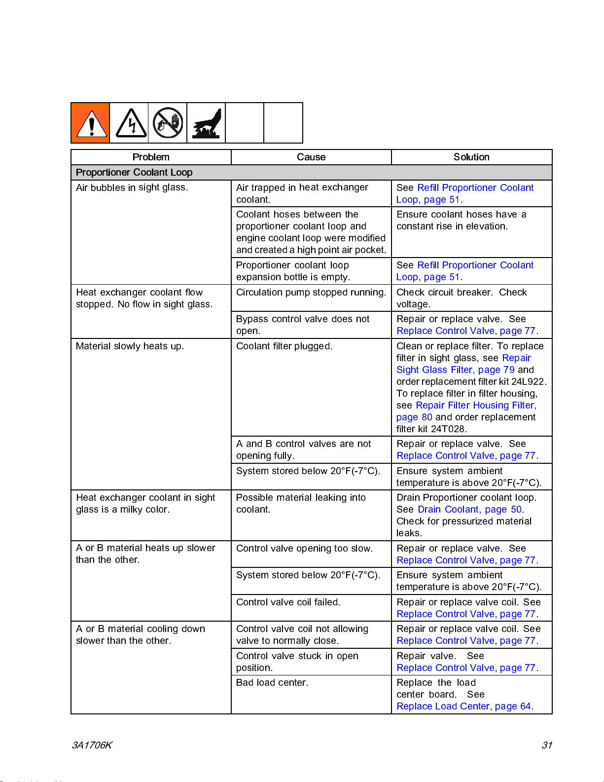
Coolant System
Problem Cause Solution
Proportioner Coolant Loop
Air bubbles in
Heat exchanger coolant flow
stopped. No flow in sight glass.
Material slowly heats up.
Heat exchanger coolant in sight
glassisamilkycolor.
A or B material heats up slower
than the other.
A or B material cooling down
slower than the other.
sight glass.
Troubleshooting
Air trapped in
coolant.
Coolant hoses between the
proportioner coolant loop and
engine coolant loop were modified
and created a high point air pocket.
Proportion
expansion b
Circulation pump stopped running. Check circuit breaker. Check
Bypass con
open.
Coolant filter plugged. Clean or replace filter. To replace
AandBc
gfully.
openin
System stored be low 20°F(-7°C).
Possible material leaking into
coolant.
Control valve opening too slow. Repair or replace valve. See
System stored be low 20°F(-7°C).
Control valve coil failed. Repair or replace valve coil. See
Control valve coil not allowing
valvetonormallyclose.
Control valve stuck in open
position.
Bad load center. Replace the load
heat exchanger
er coolant loop
ottle is empty.
trol valve does not
ontrol valves are not
See Refill Proportioner Coolant
Loop, page 51.
Ensure coolant hoses have a
constant rise in elevation.
See Refill Proportioner Coolant
Loop, page 51.
voltage.
Repair or replace valve. See
Replace Control Valve, page 77.
filter in sight glass, see Repair
Sight Glass Filter, page 79 and
order replacement filter kit 24L922.
To replace filter in filter housing,
see Repair Filter Housing Filter,
page 80 and order replacement
filter kit 24T028.
Repair or replace valve. See
Replace Control Valve, page 77.
Ensure system a mbi en t
temperature is above 20°F(-7°C).
Drain Proportioner cool ant loop.
See Drain Coolant, page 50.
Check for pressurized material
leaks.
Replace Control Valve, page 77.
Ensure system a mbi en t
temperature is above 20°F(-7°C).
Replace Control Valve, page 77.
Repair or replace valve coil. See
Replace Control Valve, page 77.
Repair valve. See
Replace Control Valve, page 77.
center board. See
Replace Load Center, page 64.
3A1706K 31
Page 32
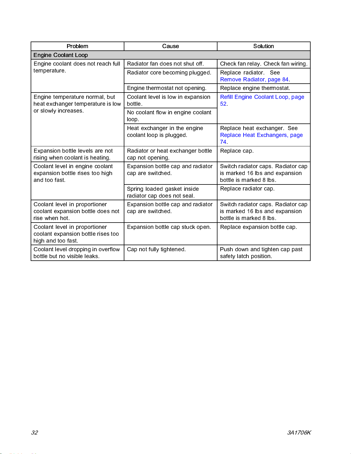
Troubleshooting
Problem Cause Solution
Engine Coolant Loop
Engine coolant does not reach full
temperature.
Engine temperature normal, but
heat exchanger temperature is low
or slowly increases.
Expansion bottle levels are not
rising when coolant is heating.
Coolant level in engine coolant
expansion bottle rises too high
and too fast.
Coolant level in proportioner
coolant expansion bottle does not
rise when hot.
Coolant level in proportioner
coolant expansion bottle rises too
high and too fast.
Coolant level dropping in overflow
bottle but no visible leaks.
Radiator fan does not shut off. Check fan relay. Check fan wiring .
Radiator core becoming plugged.
Engine thermostat not opening. Replace engine thermostat.
Coolant level is low in expansion
bottle.
No coolant flow in engine coolant
loop.
Heat exchanger in the engine
coolant loop is plugged.
Radiator or heat exchanger bottle
cap not opening.
Expansion bottle cap and radiator
cap are switched.
Spring loaded gasket inside
radiator cap does not seal.
Expansion bottle cap and radiator
cap are switched.
Expansion bottle cap stuck o pen. Replace expansion bottle cap.
Cap not fully tightened.
Replace radiator. See
Remove Radiator, page 84.
Refill Engine Coolant Loop, page
52.
Replace heat exchanger. See
Replace Heat Exchangers, page
74.
Replace cap.
Switch radiator caps. Radiator cap
is marked 16 lbs and expansion
bottleismarked8lbs.
Replace radiator cap.
Switch radiator caps. Radiator cap
is marked 16 lbs and expansion
bottleismarked8lbs.
Push down and tighten cap past
safety latch position.
32 3A1706K
Page 33
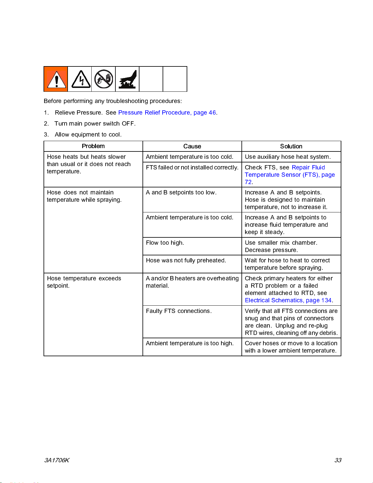
Hose Heat System
Before performing any troubleshooting procedures:
1. Relieve Pressure. See Pressure Relief Procedure, page 46.
2. Turn main power switch OFF.
3. Allow equipment to cool.
Troubleshooting
Problem
than usual or it does not reach
temperature.
Hose does not maintain
temperature while spraying.
Hose temperature exceeds
setpoint.
Cause Solution
Ambient temperature is too cold. Use auxiliary hose heat system.Hose heats but heats slower
FTS failed or not insta lled correctly. Check FTS, see Repair Fluid
Temperature Sensor (FTS), page
72.
A and B setpoints too low. Increase A and B setpoints.
Hose is designed to maintain
temperature, not to increase it.
Ambient temperature is too cold. Increase A and B setpoints to
increase fluid temperature and
keep it steady.
Flow too high. Use smaller mix chamber.
Decrease pressure.
Hose was not fully preheated. Wait for hose to heat to correct
temperature before s pray i ng.
A and/or B heaters are overheating
material.
Faulty FTS connections. Verify that all FTS connections are
Check primary heaters for either
a RTD problem or a failed
element attached to RTD, see
Electrical Schematics, page 134.
snug and that pins of connectors
are clean. Unplug and re-plug
RTD wires, cleaning off any debris.
Ambient temperature is too high.
3A1706K 33
Cover hoses or move to a location
with a lower ambient temperature.
Page 34
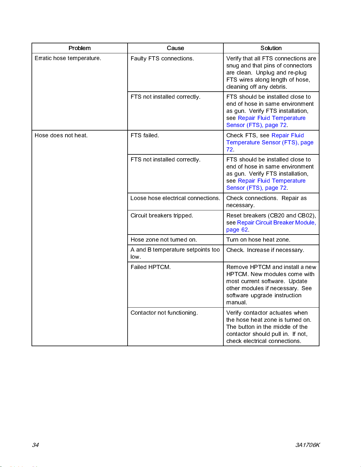
Troubleshooting
Problem
Erratic hose temperature.
Hose does not heat.
Cause Solution
Faulty FTS connections. Verify that all FTS connections are
snug and that pins of connectors
are clean. Unplug and re-plug
FTS wires along length of hose,
cleaning off any debris.
FTS not ins tal led correctly. FTS shoul d be install ed close to
endofhoseinsameenvironment
as gun. Verify FTS installation,
see Repair Fluid Temperature
Sensor (FTS), page 72.
FTS failed. Check FTS, see Repair Fluid
Temperature Sensor (FTS), page
72.
FTS not ins tal led correctly. FTS shoul d be install ed close to
endofhoseinsameenvironment
as gun. Verify FTS installation,
see Repair Fluid Temperature
Sensor (FTS), page 72.
Loose hose electrical connections. Check connections. Repair as
necessary.
Circuit breakers tripped. Reset breakers (CB20 and CB02),
see Repair Circuit Breaker Module,
page 62.
Hose zone not turned on. Turn on hose heat zone.
A and B temperature setpoints too
low.
Failed HPTCM. Remove HPTCM and ins tall a new
Contactor not functioning. Verify contactor actuates when
Check. Increase if necessary.
HPTCM. New modules come wi th
most current software. Update
other module s if necessary . See
software upgrade instruction
manual.
thehoseheatzoneisturnedon.
Thebuttoninthemiddleofthe
contactor should pull in. If not,
check electrical connections.
34 3A1706K
Page 35
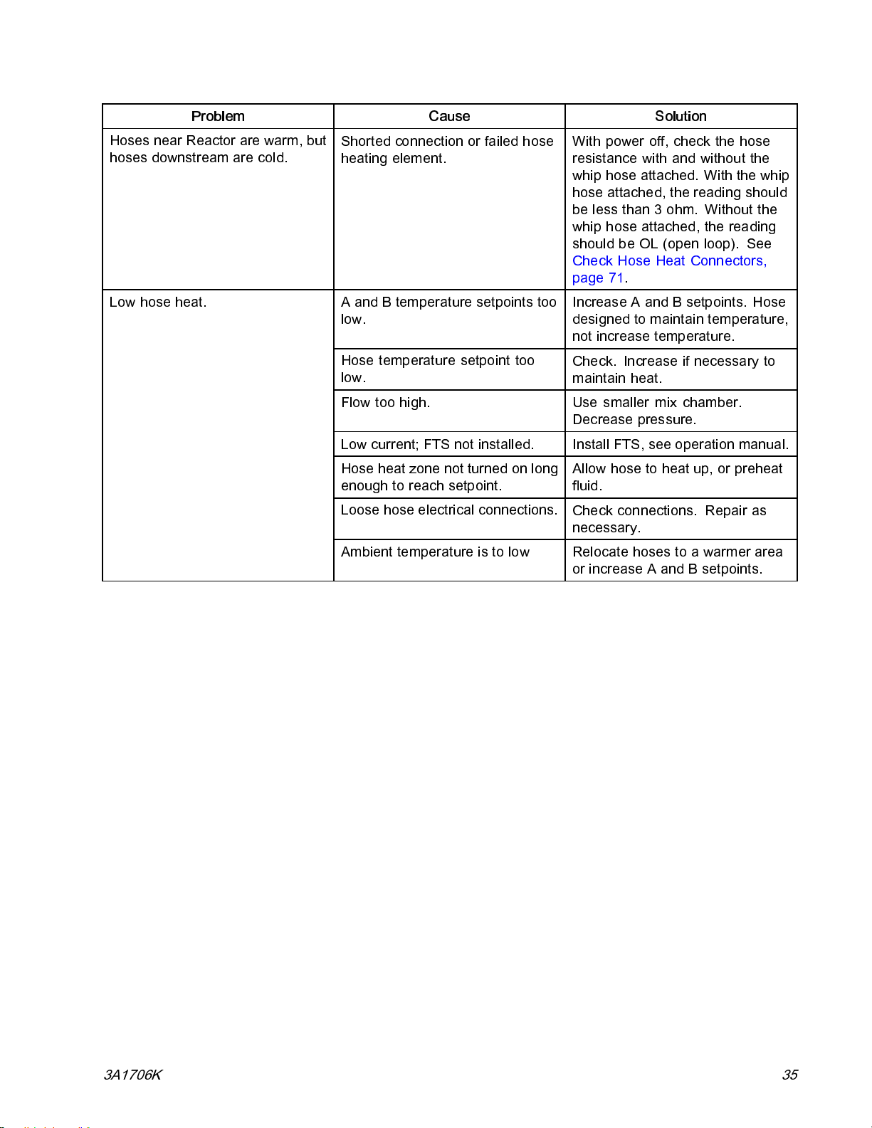
Troubleshooting
Problem
Hoses near Reactor are warm, but
hoses downstream are cold.
Low hose heat.
Cause Solution
Shorted connection or failed hose
heating element.
A and B temperature setpoints too
low.
Hose temperature setpoint too
low.
Flow too high. Use smaller mix chamber.
Low current; FTS not installed. Install FTS, see operation manual.
Hose heat zone not turned on long
enough to reach setpoint.
Loose hose electrical connections.
With power off, check the hose
resistance with and without the
whip hose attached. With the whip
hose attached, the reading should
be less than 3 ohm. Without the
whip hose attached, the reading
shouldbeOL(openloop). See
Check Hose Heat Connectors,
page 71.
Increase A and B setpoints. Hose
designed to maintain temperature,
not increase temperature.
Check. Increase if necessary to
maintain heat.
Decrease pressure.
Allow hose to heat up, or preheat
fluid.
Check connections. Repair as
necessary.
Ambient temperature is to low Relocate hoses to a warmer area
or increase A and B setpoints.
3A1706K 35
Page 36

Troubleshooting
Booster Heater
Before performing any troubleshooting procedures:
1. Relieve Pressure. See Pressure Relief Procedure, page 46.
2. Turn main power switch O FF.
3. Allow equipment to cool.
Problems
Try the recommended solutions in the order given for each problem, to avoid unnecessary repairs. Also,
determine that all circuit breakers, switches, and controls are properly set and wiring is correct before
assuming there is a problem.
Problem Cause Solution
Booster heater(s) does not heat.
Control of booster heat is
abnormal; high temperature
overshoots (T4DA, T4DB) occurs
intermittently.
Heat turned off. Turn on heat zones.
Temperature control alarm.
Signal failure from RTD. Signal failure from RTD.
Dirty RTD connections. Examine RTD cables connected
RTD not contacting heater
element.
Failed heater element. See
Signal failure from RTD. See (T4DA, T4DB), Error Codes
Check ADM for error codes.
to LPTCMs. Confirm RTDs are
not plugged into opposite heat
zone. Unplug and re-plug RTD
connectors. Unplug and re-plug
RTD connectors. Ensure RTD tip
contacts the heater element.
Loosen ferrule nut, push in RTD
so tip contacts heater element.
Holding RTD tip against heater
element, tighten ferrule nut 1/4
turn past tight.
Replace Heater Element, page 68.
and Troubleshooting, page 14.
36 3A1706K
Page 37
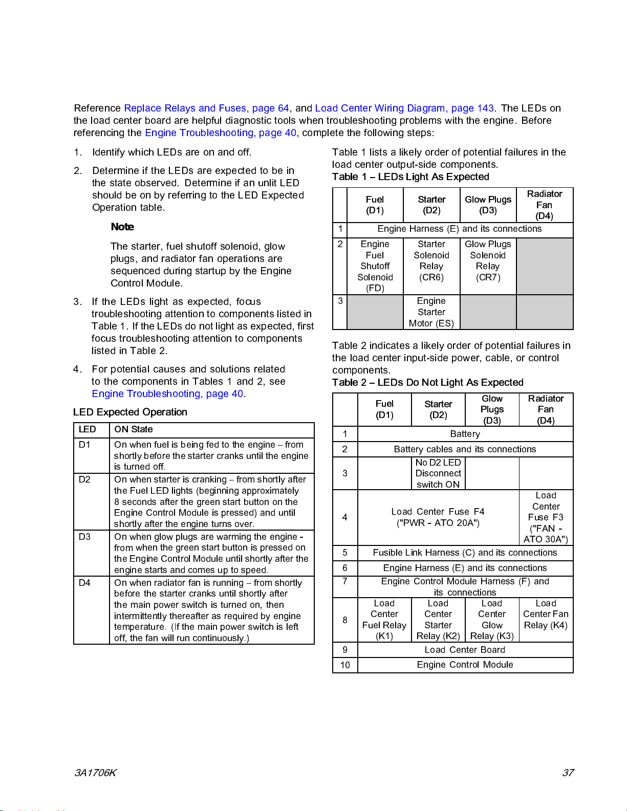
Troubleshooting
Load Center Diagnostics
Reference Replac e Relays and Fuses, page 64,andLoad Center Wiring Diagram, page 143. The LEDs on
the load center board are helpful diagnos tic tools when troubleshooting problems with the engine. Before
referencing the Engine Troubleshooti ng, page 40, complete the following steps:
1. Identify which LEDs are on and off.
2. Determine if the LEDs are expected to be in
the state observed. Determine if an unlit LED
should be on by referring to the LED Expected
Operation table.
Note
The starter, fuel shutoff solenoid, glow
plugs, and radiator fan operations are
sequenced during startup by the Engine
Control Module.
3. If the LEDs light as expected, focus
troubleshooting attention to components listed in
Table 1. If the LEDs do not light as expected, first
focus troubleshooting attention to c omponents
listed in Table 2.
4. For potential causes and solutions related
to the components in Tables 1 and 2, see
Engine Troubleshooting, page 40.
LED Expected Operation
LED
D1
D2
D3
D4 On when radiator fan is running – from shortly
ON State
On when fuel is being fed to the engine – from
shortly before the starter cranks until the engine
is turned off.
On when starter is cranking – from shortly after
the Fuel LED lights (beginning approximately
8 seconds after the green start button on the
Engine Control Module is pressed) and until
shortly after the engine turns over.
On whe
from
the E
engi
before the starter cranks until shortly after
the main power switch is turned on, then
intermittently thereafter as required by engine
temperature. (If the main power switch is left
off, the fan will run continuously.)
n glow plugs are warming the engine -
when the green start button is pressed on
ngine Control Module until shortly after the
ne starts and comes up to speed.
Table 1 lists a likely order of potential failures in the
load center output-side components.
Table 1 – LEDs Light As Expected
Fuel
(D1)
1 Engine Harness (E) and its connections
2 Engine
Fuel
Shutoff
Solenoid
(FD)
3 Engine
Starter
(D2)
Starter
Solenoid
Relay
(CR6)
Starter
Motor (ES)
Glow Plugs
(D3)
Glow Plugs
Solenoid
Relay
(CR7)
Radiator
Fan
(D4)
Table 2 indicates a likely order of potential failures in
the load center input-side power, cable, or control
components.
Table 2 – LEDs Do Not Light As Expected
Fuel
(D1)
1
2
3
4
5
6
7
8
Fuel Relay
9 Load Center Board
10
Battery cables and its connections
Load Center Fuse F4
Fusible Link Harness (C) and its connections
Engine Harness (E) and its connections
Engine Control Module Harness (F) and
Load
Center
(K1)
Starter
(D2)
Battery
No D2 LED
Disconnect
switch ON
("PWR - ATO 20A")
its connections
Load
Center
Starter
Relay (K2)
Engine Control Module
Glow
Plugs
(D3)
Load
Center
Glow
Relay (K3)
Radiator
Fan
(D4)
Load
Center
Fuse F3
("FAN -
ATO 30A")
Load
Center Fan
Relay (K4)
3A1706K 37
Page 38

Troubleshooting
Load Center Component Identificati on
Figure 1
F3 Radiator Fan Fuse
F4
K1 Fuel Relay
K2
K3
K4 Radiator Fan Relay
MV
LED
D1
D2
D3
D4 Radiator Fan
D10
D12
D14
D23
Load Cent
Starter R
Glow Plu
Manual V
Related Component
Fuel Shutoff Solenoid Green
Starter
Glow Plugs
A Coolant Valve
B Coolant Valve
Bypass Coolant Valve
Manual Valve Switch
er Power Fuse
elay
gRelay
alve Switch
Manual Valve Switch ON (engine off)
Figure 2
Color
Red
Green
Green Radiator fan is on.
Red
Blue
Green
Red
ON-State Description
Fuel shutoff solenoid on the engine is open.
Starter is cranking.
Glow plugs are heating.
A-side (red) coolant valve is open.
B-side (blue) coolant valve is open.
Bypass co ol ant valve is ope n.
Manua
l valve switch is in the ON position.
38 3A1706K
Page 39
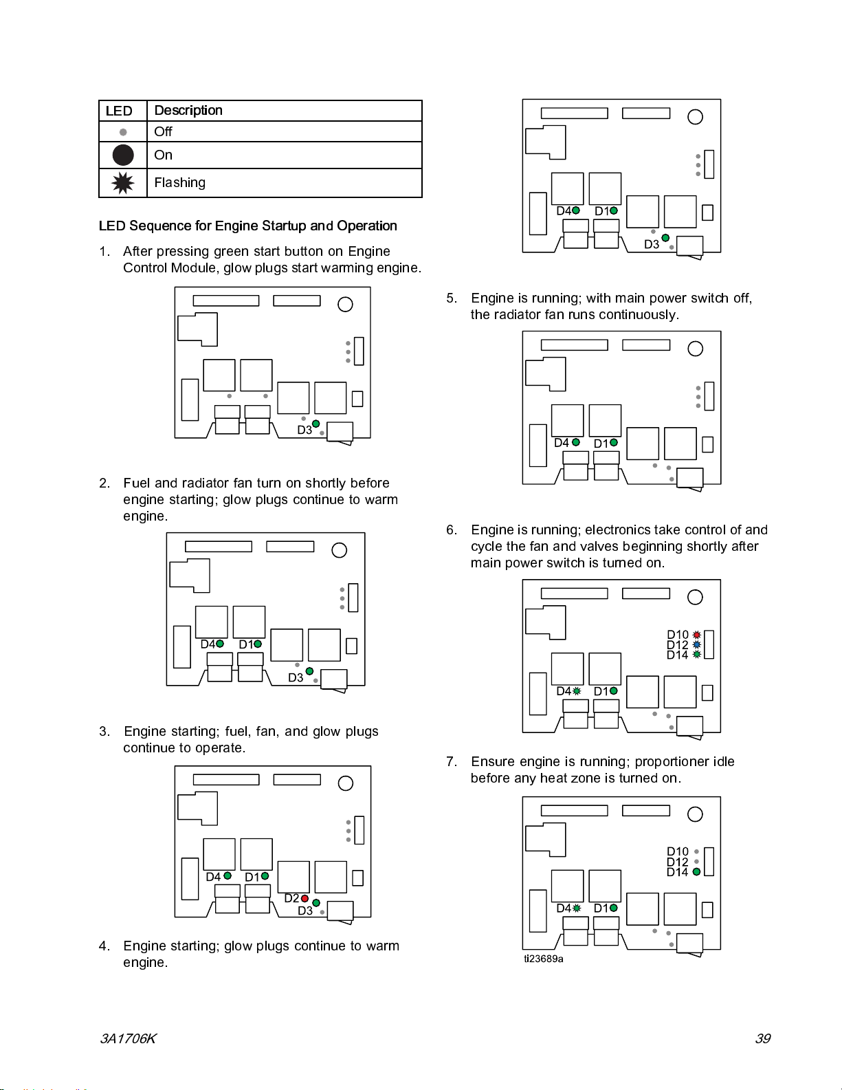
Troubleshooting
LED
LED Sequence for Engine Startup and Operation
1. After pressing green start button on Engine
2. Fuel and radiator fan turn on shortly before
Description
Off
On
Flashing
Control Module, glow plugs start warming engine.
engine starting; glow plugs continue to warm
engine.
5. Engine is running; with main power switch off,
the radiator fan runs continuously.
6. Engine is running; electronics take control of and
cycle the fan and valves beginning shortly after
main power switch is turned on.
3. Engine starting; fuel, fan, and glow plugs
continue to operate.
7. Ensure engine is running; proportioner idle
before any heat zone is turned on.
4. Engine starting; glow plugs continue to warm
engine.
3A1706K 39
Page 40
Troubleshooting
Engine
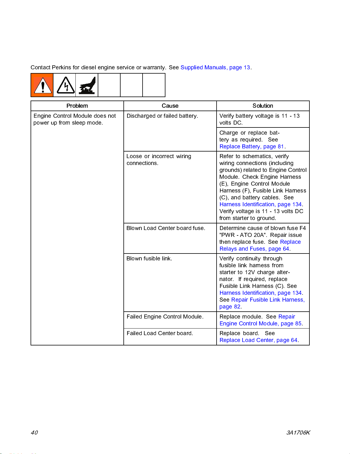
Contact Perki ns for d ie se l engine service or warranty. See Supplied Manuals, page 13.
Problem Cause Solution
Engine Control Module does not
power up from sleep mode.
Discharged or failed battery.
Loose or incorrect wiring
connections.
Blown Load Center board fuse. Determine cause of blown fuse F4
Blown fusible link. Verify continuity through
Verify battery voltage is 11 - 13
volts DC.
Charge or replace bat-
tery as required. See
Replace Battery, page 81.
Refer to schematics, verify
wiring connections (including
grounds) related to Engine Control
Module. Check Engine Harness
(E), Engine Control Module
Harness (F), Fusible Link Harness
(C), and battery cables. See
Harness Identification, page 134.
Verify voltage is 11 - 13 volts DC
from starter to ground.
"PWR - ATO 20A". Repair issue
then replace fuse. See Replace
Relays and Fuses, page 64.
fusible link harness from
starter to 12V charge alter-
nator. If required, replace
Fusible Link Harness (C). See
Harness Identification, page 134.
See Repair Fusible Link Harness,
page 82.
Failed Engine Control Module. Replace module. See Repair
Engine Control Module, page 85.
Failed Load Center board. Replace board. See
Replace Load Center, page 64.
40 3A1706K
Page 41
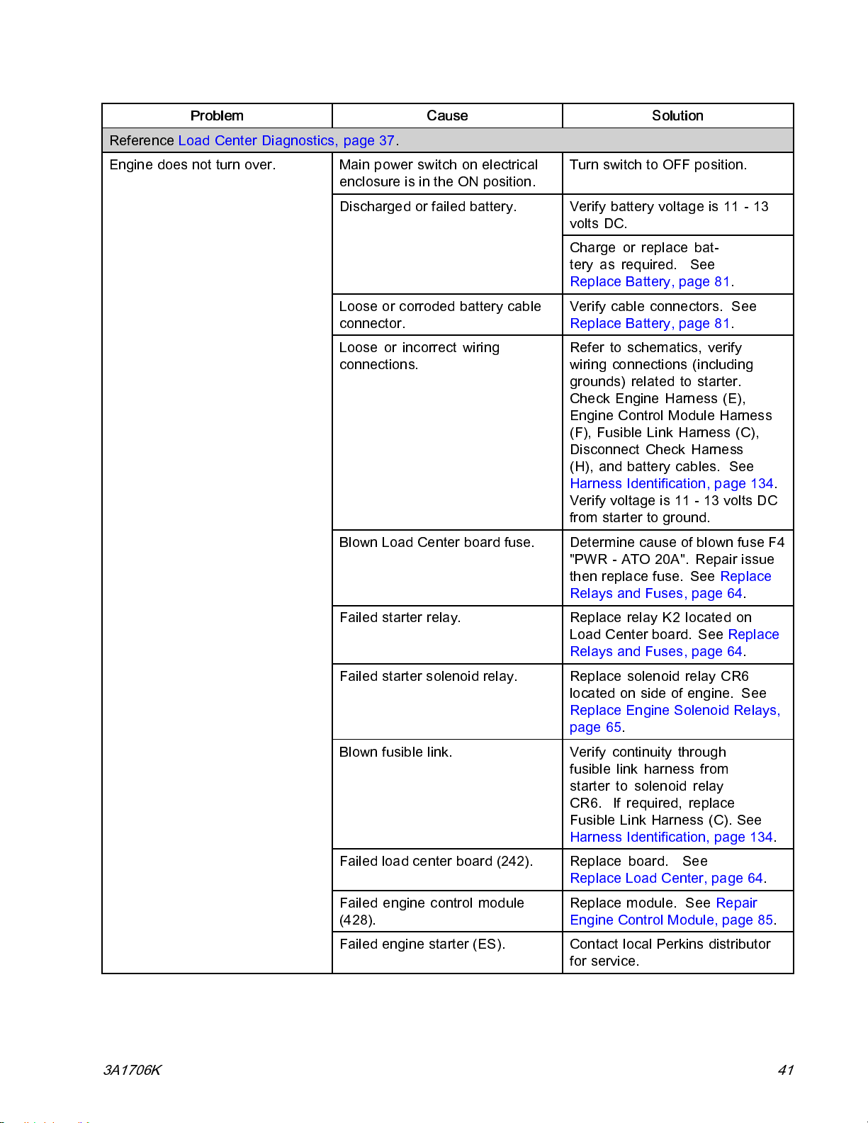
Troubleshooting
Problem
Reference Load Center Diagnostics, page 37.
Engine does not turn over.
Main power switch on electrical
enclosure is in the ON position.
Discharged or failed battery.
Loose or corroded battery cable
connector.
Loose or incorrect wiring
connections.
Cause Solution
Turn switch to OFF position.
Verify battery voltage is 11 - 13
volts DC.
Charge or replace bat-
tery as required. See
Replace Battery, page 81.
Verify cable connectors. See
Replace Battery, page 81.
Refer to schematics, verify
wiring connections (including
grounds) related to starter.
Check Engine Harness (E),
Engine Control Module Harness
(F), Fusible Link Harness (C),
Disconnect Check Harness
(H), and battery cables. See
Harness Identification, p age 134.
Verifyvoltageis11-13voltsDC
from starter to ground.
Blown Load Center board fuse. Determine cause of blown fuse F4
"PWR - ATO 20A". Repair issue
then replace fuse. See Replace
Relays and Fuses, page 64.
Failed starter relay. Replace relay K2 located on
Load Center board. See Replace
Relays and Fuses, page 64.
Failed starter s ole noi d rel ay . Replace solenoid relay CR6
locatedonsideofengine. See
Replace Engi ne Solenoid Relays,
page 65.
Blown fusible link. Verify continuity through
fusible link harness from
starter to solenoid relay
CR6. If required, replace
Fusible Link Harness (C). See
Harness Identification, page 134.
Failed load center board (242). Replace board. See
Replace Load Center, page 64.
Failed engine control module
(428).
Failed engine starter (ES). Contact local Perkins distributor
Replace module. See Repair
Engine Control Module, page 85.
for service.
3A1706K
41
Page 42

Troubleshooting
Problem
Reference Load Center Diagnostics, page 37.
Engine turns over, but does not
start.
Low fuel level. Refill fuel tank.
Lost prime.
Loose or incorrect wiring
connections.
Blocked air intake. Replace air filter.
Blocked exhaust system.
Blocked fuel filter. Inspect/replace fuel filter.
Failed fuel relay.
Cause Solution
Ensure fuel tank is at least half full,
prime with bulb until fuel is flowing
through return line to tank.
Refer to schematics, verify
wiring connections (including
to grounds) related to engine
fuel shutoff solenoid. Check
Engine Harness (E), Engine
Control Module Harness (F), and
Fusible Link Harness (C). See
Harness Identification, page 134.
Check that exhaust system is
open (rain cap is free to move, no
exhaust obstructions or plugging).
Remove blockage.
Replace relay K1 located on
Load Center board. See Replace
Relays and Fuses, page 64.
Solenoid valve rod stuck in
extended position.
Failed e ngine fuel shutoff solenoid.
Failed glow plug relay. Replace relay K3 located on
Failed glow plug solenoid rela y.
Failed glow plug assembly.
Remove valve rod and clean with
WD-40.
Verify engine fuel shutoff solenoid
(FD) related wiring according to
schematics (see Cause "Loose
or incorrect wiring connections",
above).
Contact local Perkins distributor
for service.
Load Center board. See Replace
Engine Solenoid Relays, page 65.
Replace solenoid relay CR7
locatedonsideofengine.
See Replace Engine Solenoid
Relays, page 65.
Verify glow plug related wiring
accordingtoschematics(see
Cause "Loose or incorrect wiring
connections", above).
Contact local Perkins distributor
for service.
42
3A1706K
Page 43
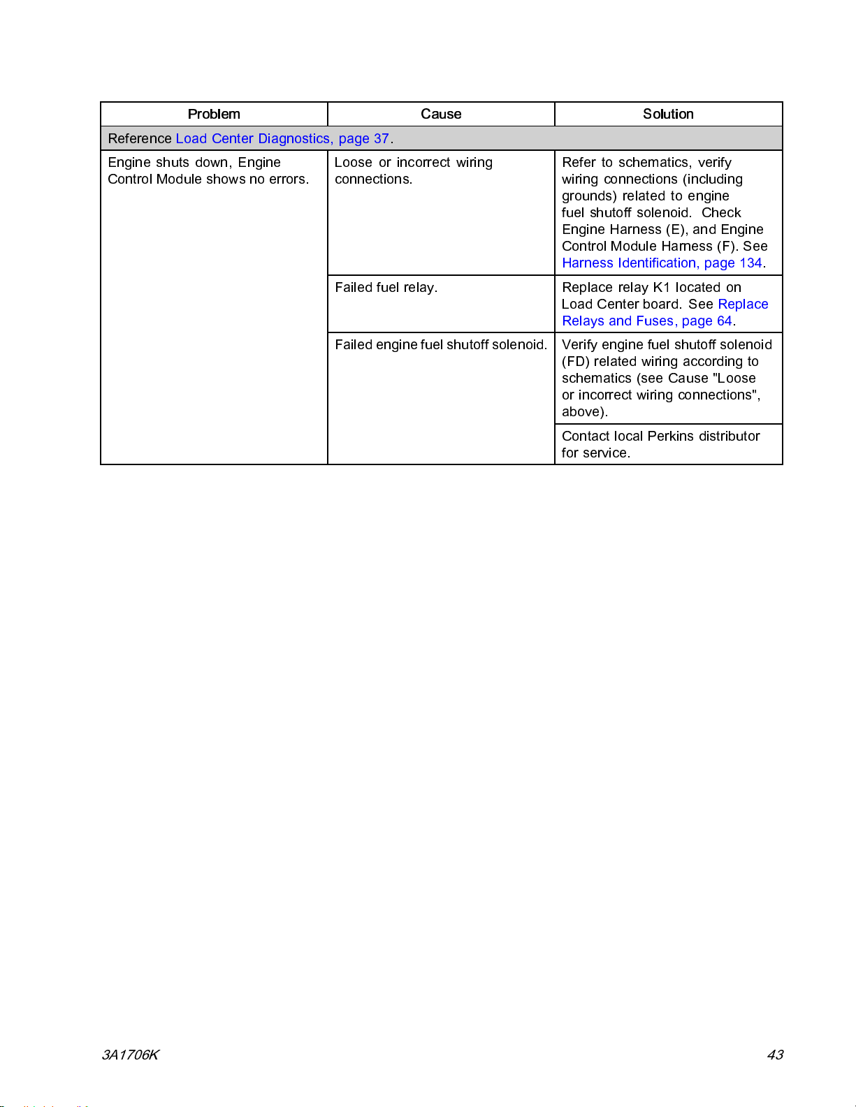
Troubleshooting
Problem
Reference Load Center Diagnostics, page 37.
Engine shuts down, Engine
Control Module shows no errors.
Loose or incorrect wiring
connections.
Failed fuel relay.
Failed engine fuel shutoff solenoid.
Cause Solution
Refer to schematics, verify
wiring connections (including
grounds) related to engine
fuel shutoff solenoid. Check
Engine Harness (E), and Engine
Control Module Harness (F). See
Harness Identification, page 134.
Replace relay K1 located on
Load Center board. See Replace
Relays and Fuses, page 64.
Verify engine fuel shutoff solenoid
(FD) related wiring according to
schematics (see Cause "Loose
or incorrect wiring connections",
above).
Contact local Perkins distributor
for service.
3A1706K 43
Page 44
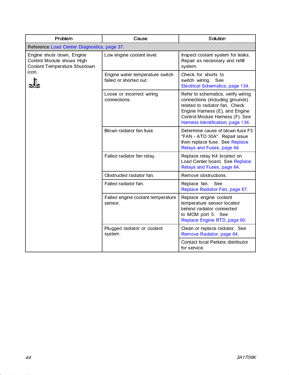
Troubleshooting
Problem
Reference Load Center Diagnostics, page 37.
Engine shuts down, Engine
Control Module shows High
Coolant Temperature Shutdown
icon.
Low engine coolant level.
Engine water temperature switch
failed or shorted out.
Loose or incorrect wiring
connections.
Blown radiator fan fuse. Determine cause of blown fuse F3
Failed radiator fan relay.
Obstructed radiator fan. Remove obstructions.
Cause Solution
Inspect coolant system for l eaks.
Repair as necessary and refill
system.
Check for shorts to
switch wiring. See
Electrical Schematics, page 134.
Refer to schematics, verify wiring
connections (including grounds)
related to radiator fan. Check
Engine Harness (E), and Engine
Control Module Harness (F). See
Harness Identification, page 134.
"FAN-ATO30A". Repairissue
then replace fuse. See Replace
Relays and Fuses, page 64
Replace relay K4 located on
Load Center board. See Replace
Relays and Fuses, page 64.
Failed radiator fan. Replace fan. See
Replace Radiator Fan, page 67.
Failed engine coolant temperature
sensor.
Plugged radiator or coolant
system.
Replace engine coolant
temperature sensor located
behind radiator connected
to MCM port 5. See
Replace Engine RTD, page 90.
Clean or replace radiator. See
Remove Radiator, page 84.
Contact local Perkins distributor
for service.
44
3A1706K
Page 45
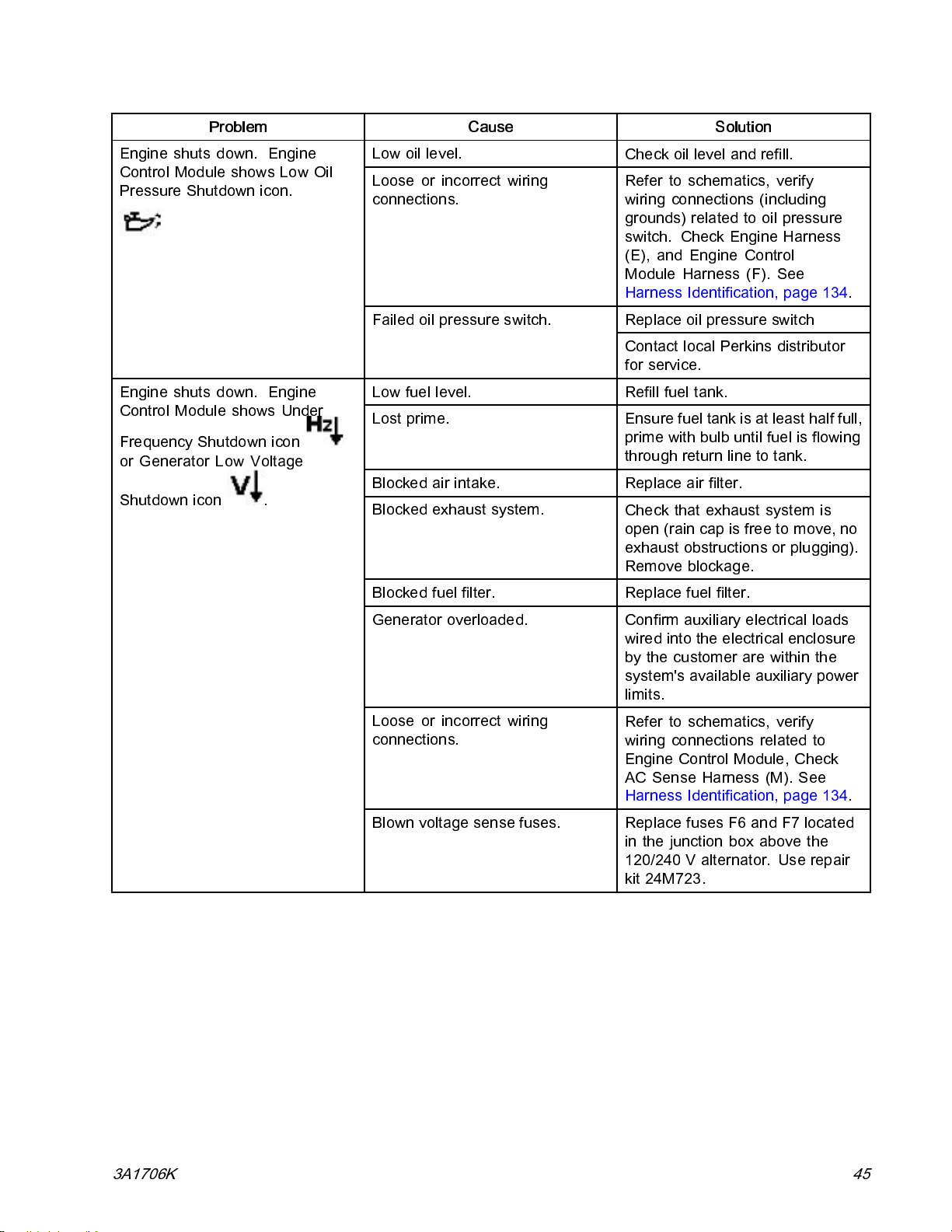
Troubleshooting
Problem
Engine shuts down. Engine
Control Module shows Lo w Oil
Pressure Shutdown icon.
Engine shuts down. Engine
Control Module shows Under
Frequency Shutdown icon
or Generator Low Voltage
Shutdown icon
.
Cause Solution
Low oil level.
Loose or incorrect wiring
connections.
Failed oil pressure switch.
Low fuel level. Refill fuel tank.
Lost prime.
Blocked air intake.
Blocked exhaust system.
Check oil level and refill.
Refer to schematics, verify
wiring connections (including
grounds) related to oil pressure
switch. Check Engine Harness
(E), and Engine Control
Module Harness (F). See
Harness Identification, page 134.
Replace oil pressure switch
Contact local Perkins distributor
for service.
Ensure fuel tank is at least half full,
prime with bulb until fuel is flowing
throughreturnlinetotank.
Replace air filter.
Check that exhaust system is
open (rain cap is free to move, no
exhaust obstructions or plugging).
Remove blockage.
Blocked fuel filter. Replace fuel filter.
Generator overloaded. Confirm auxiliary electrical loads
wired into the electrical enclosure
by the customer are within the
system's avai la bl e auxiliary power
limits.
Loose or incorrect wiring
connections.
Blown voltage sense fuses. Replace fuses F6 and F7 located
Refer to schematics, verify
wiring connections related to
Engine Control Module, Check
AC Sense Harness (M). See
Harness Identification, page 134.
in the junction box above the
120/240 V alternator. Use repair
kit 24M723.
3A1706K 45
Page 46
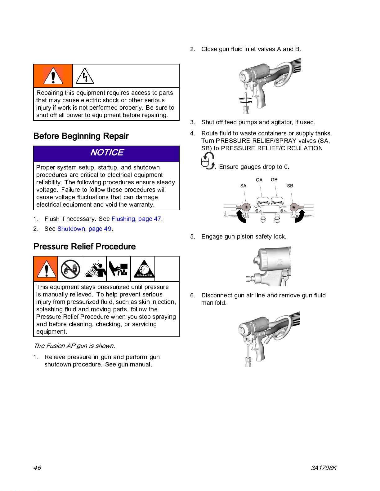
Repair
Repair
Repairing this equipment requires ac cess to parts
that may cause electric shock or other serious
injury if work is not performed properly. Be sure to
shut off all po wer to equipment before repairing.
Before Beginning Repair
NOTICE
Proper system setup, startup, and shutdown
procedures are critical to electrical equipment
reliability. The following procedures ensure steady
voltage. Failure to follow these procedures will
cause voltage fluctuations that can damage
electrical equ ip men t and void the warranty.
1. Fl us h if nec es sa ry. See Flushing, page 47.
2. See Shutdown, page 49.
2. Close gun fluid inlet valves A and B.
3. Shut off feed pumps and agitator, if used.
4. Route fluid to waste containers or supply tanks.
Turn PRESSURE RELIEF/SPRAY valve s (SA,
SB) to PRESSURE RELIEF/CIRCULATION
. Ensure gauges drop to 0.
5. Engage gun piston safety lock.
Pressure Relief Procedure
This equi pme nt stays pressuriz ed until pressu re
is manually relieved. To help prevent serious
injury from pressurized fluid, such as skin injection,
splashing fluid and moving parts, follow the
Pressure Relief Procedure when you stop spraying
and before cleaning, checking, or servicing
equipment.
The Fusion AP gun is shown.
1. Relieve pressure in gun and perform gun
shutdown procedure. See gu n manual.
6. Disconnect gun air line and remove gun fluid
manifold.
46 3A1706K
Page 47
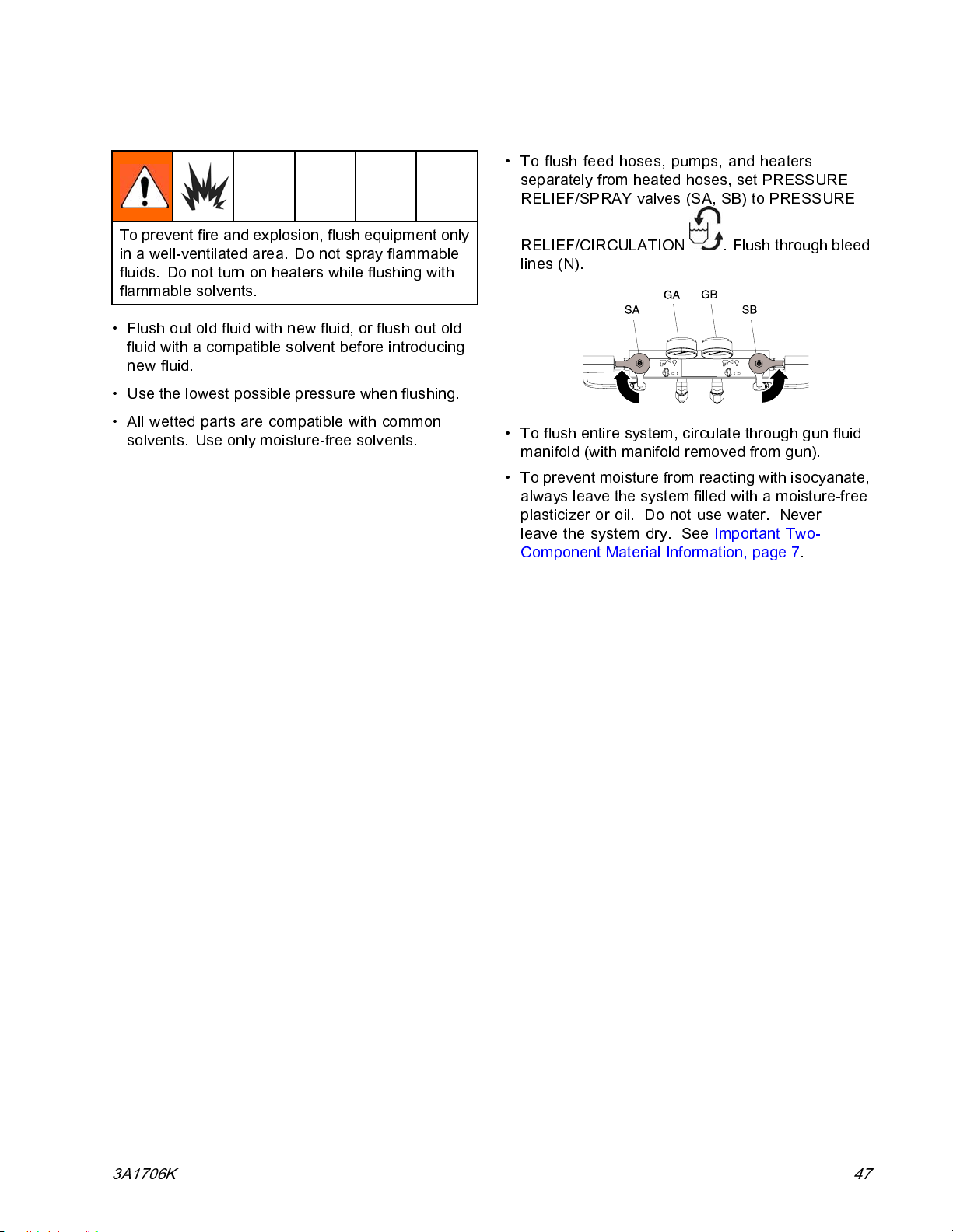
Flushing
Repair
• To flush feed hoses, pumps, and heaters
separately from heated hoses, set PRESSURE
RELIEF/SPRAY valves (SA, SB) to PRESSURE
To prevent fire and explosion, flush equipment only
in a well-ventilated area. Do not spray flammable
fluids. Do not turn on heaters while flushin g with
flammable solvents.
• Flush out old fluid with new fluid, or fl ush out old
fluid with a compatible solvent before introducing
new fluid.
• Use the lowest possible pressure when flushing.
• All wetted parts are compatible with co mmon
solvents. Use only moisture-free solvents.
RELIEF/CIRCULATION
lines (N).
• To flush entire system, circulate through gun fluid
manifold (with manifold removed from gun).
• To prevent mois ture from reac ting with i so cy an ate,
always leave the system filled with a moisture-free
plasticizer or oil. Do not use water. Never
leave the system dry. See Important Two-
Component Material Information, page 7.
. Flush through bleed
3A1706K
47
Page 48
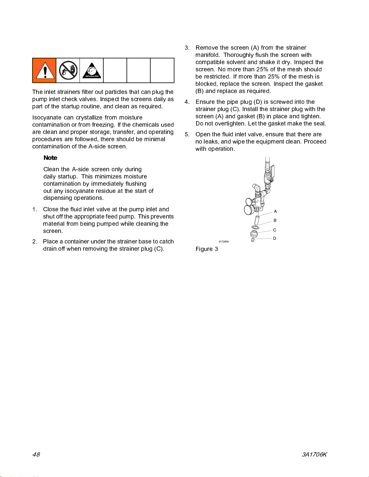
Repair
Flush Inlet Strainer Screen
The inlet strainers filter out particles that can plug the
pump inlet check valves. Inspect the screens daily as
part of the startup routine, and clean as required.
Isocyanate can crystallize from moisture
contamination or from freezing. If the chemicals used
are clean and proper storage, transfer, and operating
procedures are followed, there should be minimal
contamination of the A-side screen.
Note
Clean the A-side screen only during
daily startup. This minimizes moisture
contamination by immediately flushing
out any isocyanate residue at the start of
dispensing operations.
1. Close the fluid inlet valve at t he pump inlet and
shut off the appropriate feed pump. This prevents
material from being pumped while cleaning the
screen.
3. Remove the screen (A) from the strainer
manifold. Thoroughly flush the screen with
compatible solvent and shake it dry. Inspect the
screen. No more than 25% of the mesh should
be restricted. If more than 25% of the mesh is
blocked, replace the screen. Inspect the gasket
(B) and replace as required.
4. Ensure the pipe plug (D) is screwed into the
strainer plug (C). Install the strainer plug with the
screen (A) and gasket (B) in place and tighten.
Do not ov ertighten. Let the gasket make the seal.
5. Open the fluid inlet valve, ensure that there are
no leaks, and wipe the equipment clean. Proceed
with operation.
2. Place a containerunder the strainer base to catch
drain off when removing the strainer plug (C).
Figure 3
48 3A1706K
Page 49

Shutdown
Repair
NOTICE
Proper system setup, s ta rtup, and shutdown
procedures are critical to electrical equipment
reliability. The fo ll owi ng proc ed ures ensure steady
voltage. Failure to follow these procedures will
cause voltage fluctuations that can damage
electrical equipment and void the warranty.
1. Press to stop the pumps.
2. Turn off heat zones.
3. Relieve pressure. See
Pressure Relief Procedure, page 46.
4. Press
5. Press
6. Turn off t
breathi
7. Close th
to park the Co mponent A Pump.
eactivate th e system.
to d
he air compressor, air dryer, and
ng air.
e main air shutoff valve.
8. Turn main power switch off.
To prevent electric shock do not remove any
shrouds or open the electrical enclosure door.
240 V is still present in the system until the
engine has stopped.
9. Allow engine dwell time.
NOTICE
Allow engine dwell time, per manufacturer
recommendations, prior to shutdown. Dwell
time will help engine cool down after running at
operating temperature for any period of time.
10. Press on the engine control module.
11. Open air compressor bleed valve to relieve
pressure and remove water from tank.
12. Close all fluid supply valves.
3A1706K 49
Page 50
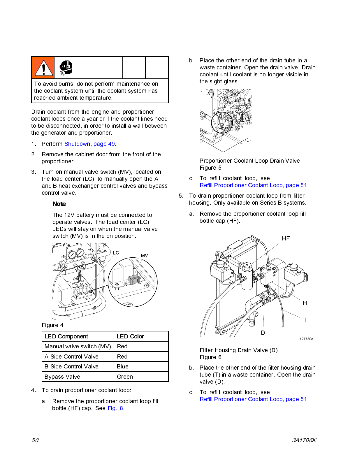
Repair
Drain Coolant
To avoid burns, do not perform m aintenance on
the cool ant system un til the coolant system has
reached ambient temperature.
Drain coolant from the engine and proportioner
coolant loops once a year or if the coolant lines need
to be disconnected, in order to install a wall between
the generator and proportioner.
1. Perform Shutdown, page 49.
2. Remove the cabinet door from the front of the
proportioner.
3. Turn on manual valve switch (MV), located on
the load center (LC), to manually open the A
and B heat exchanger control valves and bypass
control valve.
Note
The 12V battery must be connected to
operate valves. The load center (LC)
LEDs will stay on when the manual valve
switch (MV) is in the on position.
b. Place the other end of the drain tube in a
waste container. Open the drain valve. Drain
coolant until coolant is no longer visible in
the sight glass.
Proportioner Coolant Loop Drain Valve
Figure 5
c. To refill coolant loop, see
Refill Proportioner Coolant Loop, page 51.
5. To drain proportioner coolant loop from filter
housing. Only available on Series B systems.
a. Remove the proportioner coolant loop fill
bottle cap (HF).
Figure 4
LED Component LED Color
Manual valve switch (MV)
A Side Control Valve
B Side Control Valve
pass Valve
By
4. To drain proportioner coolant loop:
a. Remove the proportioner coolant loop fill
bottle (HF) cap. See Fig. 8.
50 3A1706K
Red
Red
Blue
Green
Filter Housing Drain Valve (D)
Figure 6
b. Place the other end of the filter housing drain
tube (T) in a waste container. Open the drain
valve (D).
c. To refill coolant loop, see
Refill Proportioner Coolant Loop, page 51.
Page 51
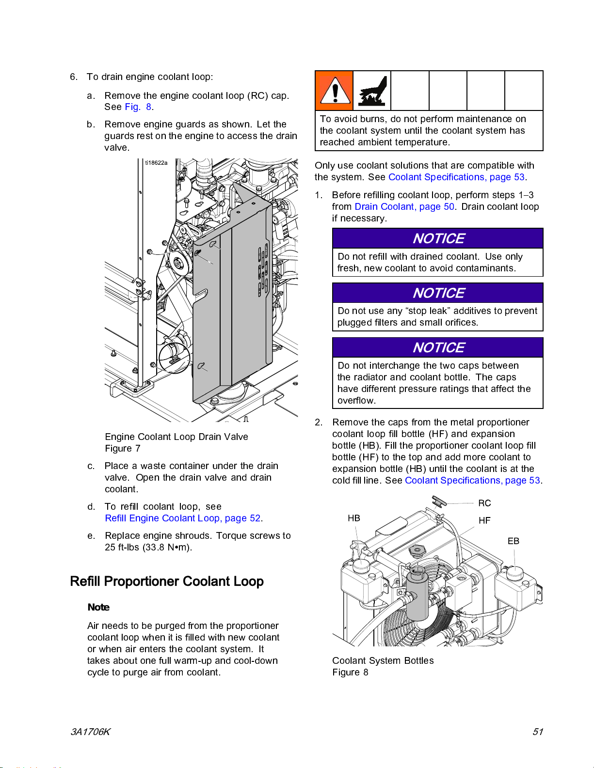
6. To drain engine coolant loop:
a. Remove the engine coolant loop (RC) cap.
See Fig. 8.
b. Remove engine guards as shown. Let the
guards rest on the engine to access the drain
valve.
Repair
To avoid burns, do not perform maintenance on
the coolan t system unti l the coolant system has
reached ambient temperature.
Only use coolant solutions that are compatible with
the system. See Coolant Specifications, page 53.
1. Before refilling coolant loop, perform steps 1–3
from Drain Coolant, page 50. Drain coolant loo p
if necessary.
NOTICE
Do not refill with drained coolant. Use only
fresh, new coolant to avoid contaminants.
NOTICE
Do not use any “stop leak” additives to prevent
plugged filters and small orifices.
Engine Coolant Loop Drain Valve
Figure 7
c. Place a waste container under the drain
valve. Open the drain valve and drain
coolant.
d. To refill coolant loop, see
Refill Engine Coolant Loop, page 52.
e. Replace engine shrouds. Torque screws to
25 ft-lbs (33.8 N∙m).
Refill Proportioner Coolant Loop
Note
Air needs to be purged from the proportioner
coolant loop when it is filled with new coolant
or when air ente rs the cool ant system. It
takes about one full warm-up and cool-down
cycle to purge air from cool ant .
NOTICE
Do not interchange the t wo caps between
the radiator and coolant bottle. The caps
have different pressure ratings that affect the
overflow.
2. Remove the caps from the metal proportioner
coolant loop fill bottle (HF) and expansion
bottle (HB). Fill the proportioner coolant loop fill
bottle (HF) to the top and add more coolant to
expansion bottle (HB) until the coolant is at the
cold fill line. See Coolant Specifications, page 53.
Coolant System Bottles
Figure 8
3A1706K 51
Page 52
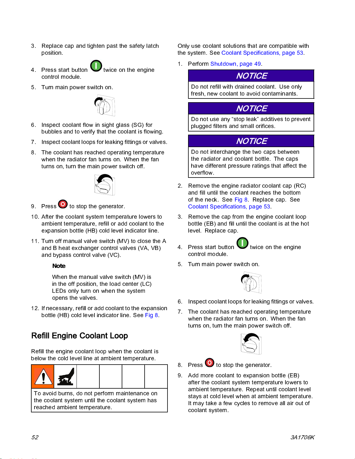
Repair
3. Replace cap and tighten past the safety latch
position.
4. Press start button
control module.
5. Turn main power switch on.
6. Inspect coolant flow in sight glass (SG) for
bubbles and to verify that the coolant is flowing.
7. Inspect coolant loops for leaking fittings or valves.
8. The coolant has reached operating temperature
when the radiator fan turns on. When the fan
turns on, turn the main power switch off.
9. Press to stop the generator.
twice on the engine
Only use coolant solutions that are compatible with
the system. See Coolant S pecifications, page 53.
1. Perform Shutdown, page 49.
NOTICE
Do not refill with drained coolant. Use only
fresh, new coolant to avoid c ontaminants.
NOTICE
Do not use any “stop leak” additives to prevent
plugged filters and small orifices .
NOTICE
Do not interchange the two caps between
the radiator and coolant bottle. The caps
have different pressure ratings that affect the
overflow.
2. Remove the engine radiator coolant cap (RC)
and fill until the coolant reaches the bottom
of the neck. See Fig 8.Replacecap.See
Coolant Specifications, page 53.
10. After the coolant system temperature lowers to
ambient temperature, refill or add coolan t to the
expansion bottle (HB) cold level indicator line.
11.Turnoffmanualvalveswitch(MV)toclosetheA
and B heat exchanger control valves (VA, VB)
and bypass control valve (VC).
Note
When the manual valve switch (MV) is
in the off position, the load center (LC)
LEDs only turn on when the system
opens the valves.
12. If necessary, refill or add coolant to the expansion
bottle (HB) cold level indicator line. See Fig 8.
Refill Engine Coolant Loop
Refill the engine coolant loop when the coolant is
below the cold level line at ambient temperature.
To avoid burns, do not perform m aintenance on
the cool ant system un til the coolant system has
reached ambient temperature.
3. Remove the cap from the engine coolant loop
bottle (EB) and fill unti l the coolant is at the hot
level. Replace cap.
4. Press start button
control m odule.
5. Turn main power switch o n.
6. Inspect coolant loops for leaking fittings or valves.
7. The coolant has reached operating temperature
when the radiator fan turns on. When the fan
turns on, turn the main power switch off.
8. Press to stop the generator.
9. Add more coolant to expansion bottle (EB)
after the coolant system temperature lowers to
ambient temperature. Repeat until coolant level
stays at cold level when at ambient temperature.
It may take a few cycles to remove all air out of
coolant system.
twiceontheengine
52 3A1706K
Page 53

Repair
Coolant Specifications
NOTICE
Do not refill with straight water or tap water.
Changing the 50% mix ratio use of tap water will
allow fittings to rust.
Only refill the coolant loops with a solution of 50%
distilled or soft water and 50% green ethylene glycol
antifreeze with a corrosion inhibitor. Do not use
common tap water; it contains chlorides and minerals
which form scale on the coolant system walls. Do n ot
use any stop leak products. The additives in these
products will clog the heat exchanger and fluid valves,
decreasing system performance. Use only antifreeze
that meets specification ASTM D3306–89, BS658, or
AS 2108. A pre-diluted mix is recommended, such
as PEAK Ready Use 50/50 Pre-Diluted.
Change Pump Lubricant
Check the c ond iti on o f the ISO pump lubric ant daily.
Change the lubricant if it becomes a gel, its color
darkens, or it becomes diluted with is oc y ana te.
1. Follow Pressure Rel ief Procedure, page 46.
2. Lift the lubricant reservoir (R) out of the bracket
and remove the container from the cap. Holding
the cap over a suitable container, remove the
check valve and allow the lubricant to drain.
Reattach the check valve to th e inlet hose.
3. Drain the reservoir and flush it with clean
lubricant.
4. When the reservoir is flushed clean, fill with fresh
lubricant.
5. Thread the reservoir onto the cap assembly and
place it in the bracket.
6. The lubrication system is ready for operation. No
priming is required.
Gel formation is due to moisture absorption by the
pump lubricant. The interval between changes
depends on the environment in which the equipment
is operating. The pump lubrication system minimizes
exposure to moisture, but some contamination is still
possible.
Lubricant discoloration is due to continual seepage of
small amounts o f iso cy an ate past t he pum p pa ck i ngs
during operation. If the packings are operating
properly, lubri ca nt replacement due to discoloration
should not be necessary more often than every 3 or
4weeks.
To change pump lubrica nt:
Pump Lubric at ion System
Figure 9
3A1706K 53
Page 54
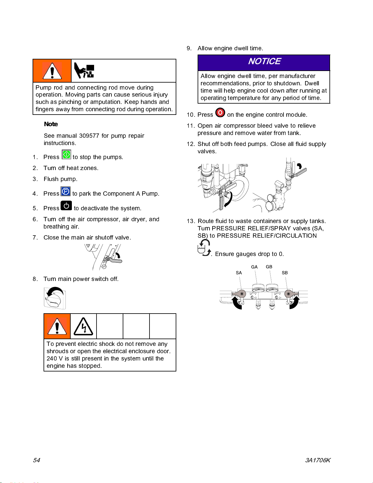
Repair
Remove Pump
Pump rod and connecting rod move during
operation. Moving parts can cause serious injury
such as pinching or amputati on. Keep hands and
fingers away from connecting rod during operation.
Note
See manual 309577 for pump repair
instructions.
1. Press
2. Turn off heat zones.
3. Flush pump.
4. Press
5. Press
6. Tu rn off the air compre ss or, air dryer, and
breathing air.
7. Close the main air shutoff valve.
to stop the pumps.
to park the Component A Pump.
to deactivat e the system.
9. Allow engine dwell time.
NOTICE
Allow engine dwell time, per manufacturer
recommendations, prior to shutdown. Dwell
time will help engine cool down after running at
operating temperature for any period of time.
10. Press on the engine control module.
11. Open air compressor bleed valve to relieve
pressure and remove water from tank.
12. Shut off both feed pumps. Close all fluid supply
valves.
13. Route flu
Turn PRE
SB) to PR
id to waste containers or supply tanks.
SSURE RELIEF/SPRAY valves (SA,
ESSURE RELIEF/CIRCULATION
8. Turn main power switch off.
To prevent electric shock do not remove any
shrouds or open the electrical enc losure door.
240 V is stil l present in the sys tem until th e
engine has stopped.
. Ensur
e gauges drop to 0.
54 3A1706K
Page 55
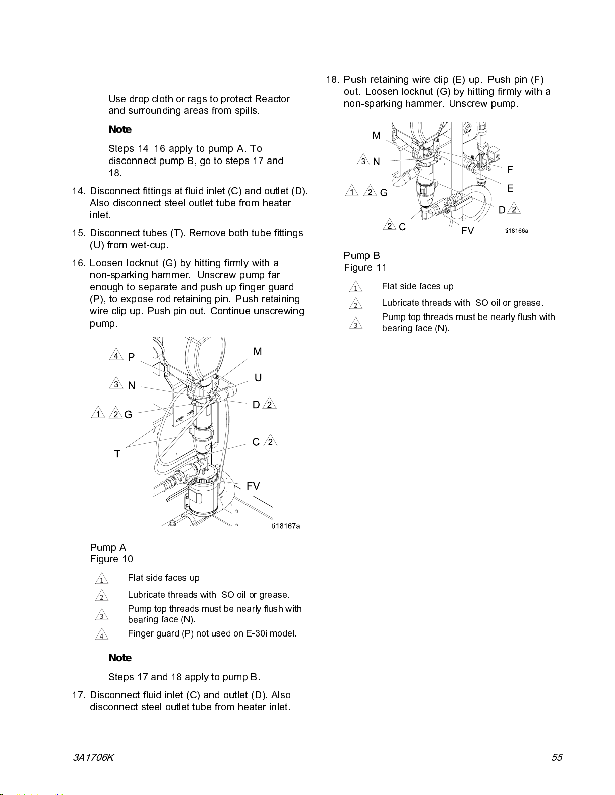
Repair
Note
Use drop cloth or rags to protect Reactor
and surrounding areas from spills.
Note
Steps 14–16 apply to pump A. To
disconnect pump B, go to steps 17 and
18.
14. Disconnect fittings at fluid inlet (C) and outlet (D).
Also disconnect steel out let tube from heater
inlet.
15. Disconnect tubes (T). Remove both tube fittings
(U) from wet-cup.
16. Loosen locknut (G) by hitting firmly with a
non-sparking hammer. Unscrew pump far
enough to separate and push up finger guard
(P), to expose rod retaining pin. Push retaining
wire clip up. Push pin out. Continue unscrewing
pump.
18. Push retaining wire clip (E) up. Push pin (F)
out. Loosen locknut (G) by hitting firmly with a
non-sparking hammer. Unscrew pump.
Pump B
Figure 11
Flat side faces up.
1
Lubricate threads with ISO oil or grease.
2
Pump top threads must be nearly flush with
3
bearing face (N).
Pump A
Figure 10
Flat side faces up.
1
Lubricate threads with ISO oil or grease.
2
p top threads must be nearly flush with
Pum
3
4
ring face (N).
bea
Finger guard (P) not used on E-30i model.
Note
Steps 17 and 18 apply to pump B.
17. Disconnect fluid inlet (C) and outlet (D). Also
disconnect steel outlet tube from heater inlet.
3A1706K 55
Page 56
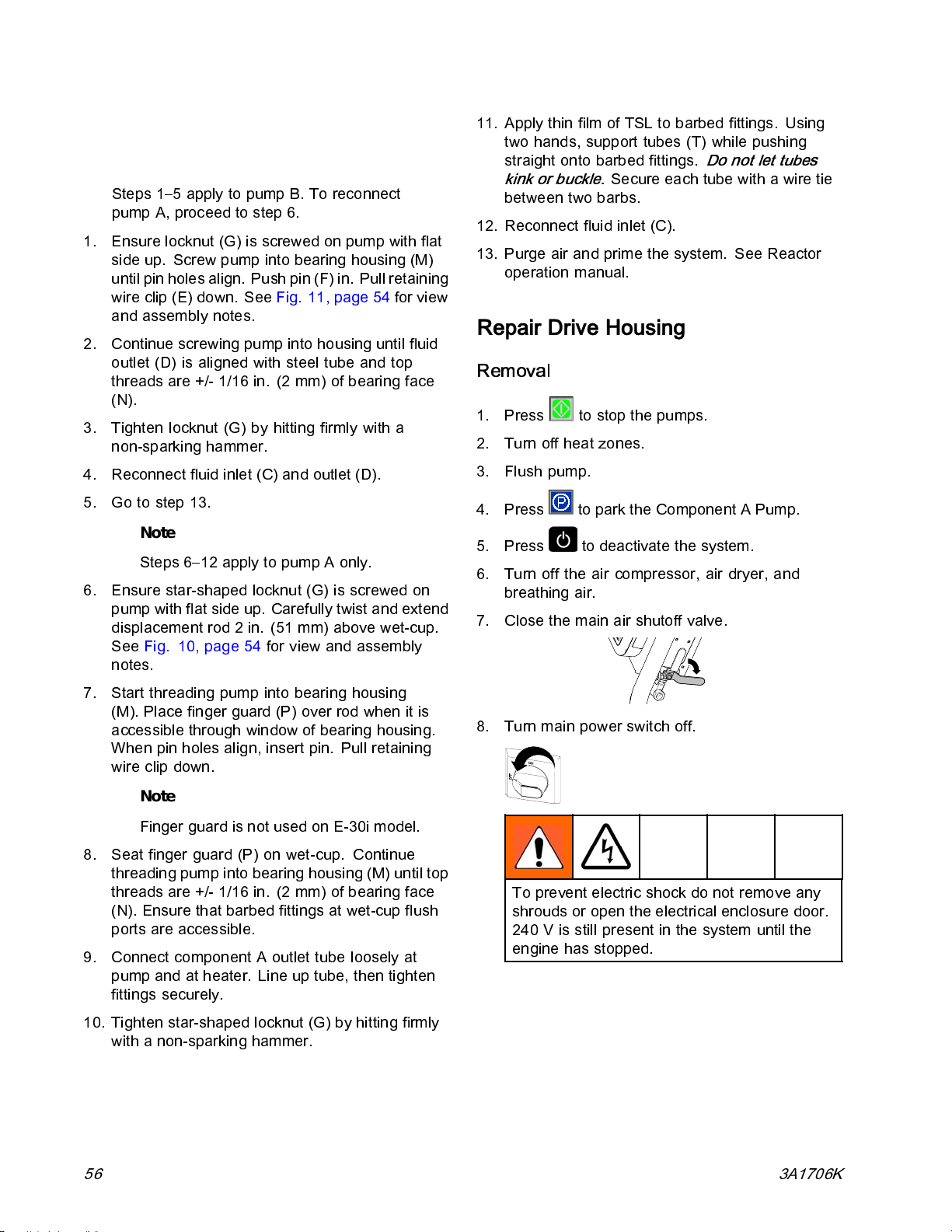
Repair
Install Pump
Note
Steps 1–5 apply to pump B. To reconnect
pump A, proceed to ste p 6.
1. Ensure locknut (G) is screwed on pump with flat
side up. Screw pump into bearing housing (M)
until pi n holes align. Push pin (F) in. Pull retaining
wire clip (E) down. See Fig. 11, page 54 for view
and assembly notes.
2. Continue screwing pump into housing until fluid
outlet (D) is aligned with steel tube and top
threads are +/- 1/16 in. (2 mm) of bearing face
(N).
3. Tighten locknut (G) by hitting firmly with a
non-sparking hammer.
4. Reconnect fluid inlet (C) and outlet (D).
5. Go to step 13.
Note
Steps 6–12 apply to pump A only.
6. Ensure star-shaped locknut (G) is screwed on
pump with flat side up. Carefully twist and extend
displacement rod 2 in. (51 mm) above wet-cup.
See Fig. 10, page 54 for view and assembly
notes.
11. Apply thin film of TSL to barbed fittings. Using
two hands, support tubes (T) while pushing
straight onto barbed fittings.
kink or buckle.
between two barbs.
12. Reconnect fluid inlet (C).
13. Purge air and prime the system. See Reactor
operation manual.
Secureeachtubewithawiretie
Do not let tubes
Repair Drive Housing
Removal
1. Press to stop the pumps.
2. Turn off heat zones.
3. Flush pump.
4. Press
5. Press
6. Tu rn off the air compres s or, air dryer, and
breathing air.
7. Close the main air shutoff valve.
to park the Component A Pump.
to deactivate the system.
7. Start threading pump into bearing housing
(M). Place finger guard (P) over rod when it is
accessible through window of bearing housing.
When pin holes align, insert pin. Pull retaining
wire clip down.
Note
Finger guard is not us ed on E-30i model.
8. Seat finger guard (P) on wet-cup. Continue
threading pump into bearing housi ng (M) until top
threads are +/- 1/16 in. (2 mm) of bearing face
(N). Ensure that barbed fittings at wet-cup flush
ports are accessible.
9. Connect component A outlet tube loosely at
pump and at heater. Line up tube, then tighten
fittings securely.
10. Tighten star-shaped locknut (G) by hitting firmly
with a non-sparking hammer.
8. Turn main power switch off.
To prevent electric shock do not remove any
shrouds or open the electrical enclosure door.
240 V is stil l present in the syst em until the
engine has stopped.
56 3A1706K
Page 57
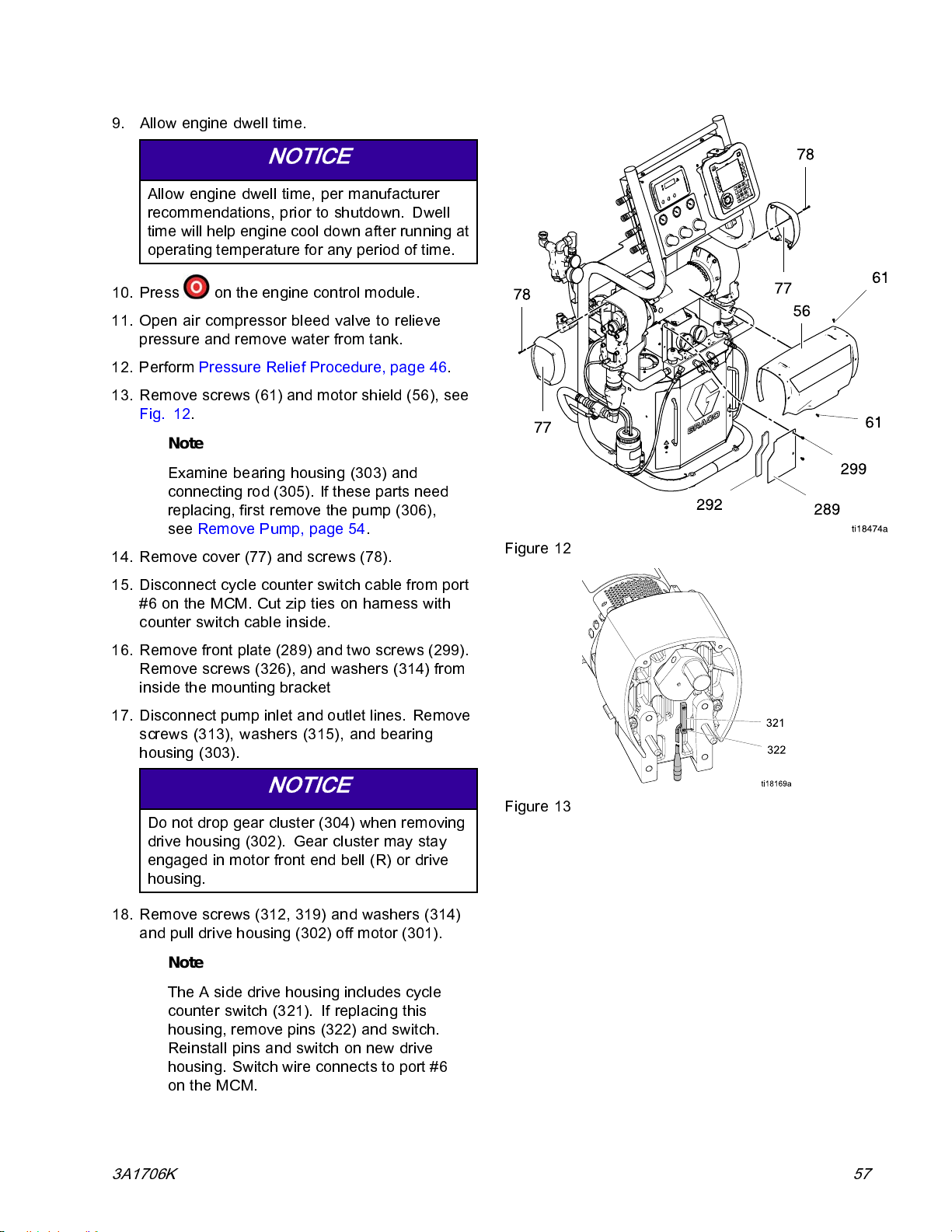
9. Allow engine dwell time.
NOTICE
Allow engine dwell time, per manufacturer
recommendations, prior to shutdown. Dwell
time will help engine cool down after runnin g at
operating temperature for any period of time.
10. Press on the engine control mod ule.
11. Open air compressor bleed valve to relieve
pressure and remove water from tank.
12. Perform Pressure Relief Proc edure, page 46.
13. Remove screws (61) and motor shield (56), see
Fig. 12.
Note
Examine bearing housing (303) and
connecting rod (305). If these parts need
replacing, first remove the pump (306),
see Remove Pump, page 54.
14. Remove cover (77) and screws (78).
Repair
Figure 12
15. Discon nec t c y cl e counter switch cab le from port
#6ontheMCM.Cutziptiesonharnesswith
counter switch cable inside.
16. Remove front plate (289) and two screws (299).
Remove screws (326), and washers (314) from
inside the mounting bracket
17. Disconnect pump inl et and outlet lines. Remove
screws (313), washers (315), and bearing
housing (303).
NOTICE
Do not drop gear c luster (304) when removing
drive housing (302). Gear cluster may stay
engaged in motor front end bell (R) or drive
housing.
18. Remove screws (312, 319) and washers (314)
and pull drive housing (302) off motor (301).
Note
The A side drive housing includes cycle
counter switch (321). If replacing this
housing, remove pins (322) and switch.
Reinstall pins and switch on new drive
housing. Switch wire connects to port #6
on the MCM.
Figure 13
3A1706K 57
Page 58
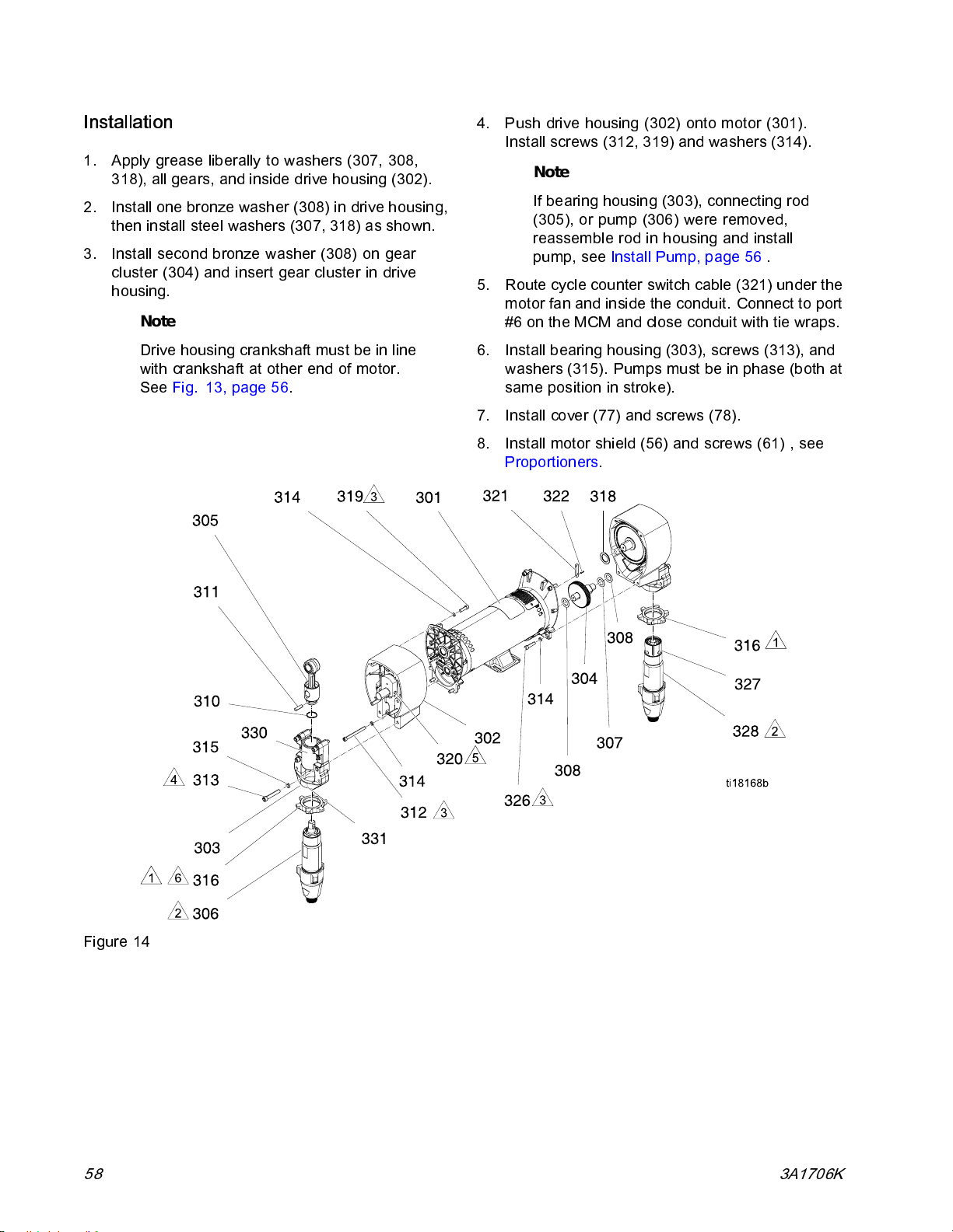
Repair
Installation
1. Apply grease liberally to washers (307, 308,
318), all gears, and inside drive housing (302).
2. Install one bronze washer (308) in drive housing,
then install steel washers (307, 318) as shown.
3. Install second bronze washer (308) on gear
cluster (304) and insert gear cluster in drive
housing.
Note
Drive housing crankshaft must be in line
with crankshaft at other end of motor.
See Fig. 13, page 56.
4. Push drive housing (302) onto motor (301).
Install screws (312, 319) and washers (314).
Note
If bearing housing (303), connecting rod
(305), or pump (306) were removed,
reassemblerodinhousingandinstall
pump, see Install Pump, page 56 .
5. Route cycle counter switch cable (321) under the
motor fan and inside the conduit. Connect to port
#6 on the MCM and close conduit with tie wraps.
6. Install bearing housing (303), screws (313), and
washers (315). Pumps must be in phase (both at
same position in stroke).
7. Install cover (77) and screws (78).
8. Install motor shield (56) and screws (61) , see
Proportioners.
Figure 14
58 3A1706K
Page 59
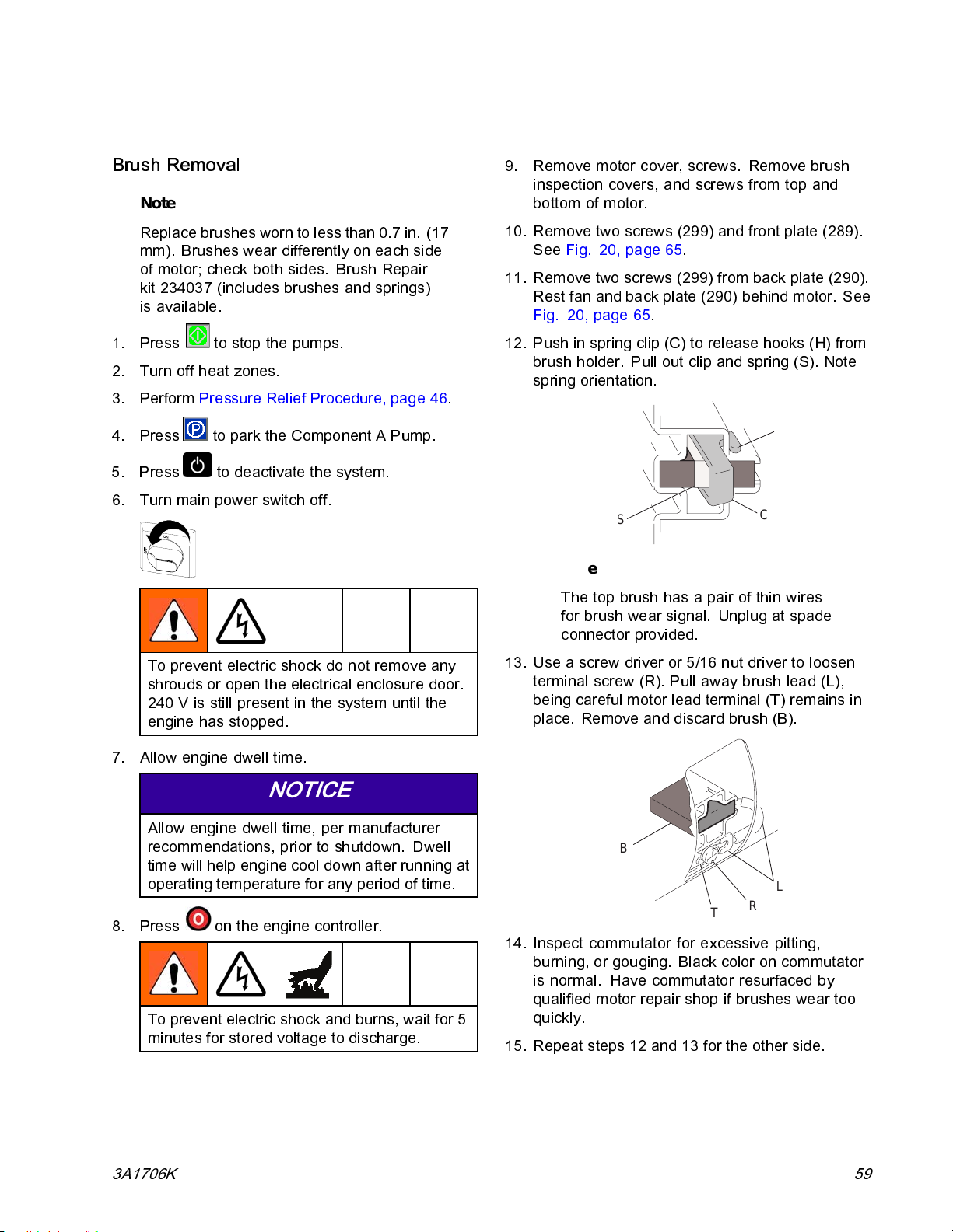
Repair Motor Brushes
Repair
Brush Removal
Note
Replace brushes worn to less than 0.7 in. (17
mm). Brushes wear differently on each side
of motor; check both sides. Brush Repair
kit 234037 (includes brushes and springs)
is available.
1. Press
2. Turn off heat zones.
3. Perform Pressure Relief Procedure, page 46.
4. Press
5. Press
6. Turn main power switch off.
to stop the pumps.
to park the Co mponent A Pump.
to deactivate the system.
9. Remove motor cover, screws. Remove brush
inspection covers, and screws from top and
bottom of motor.
10. Remove two screws (299) and front plate (289).
See Fig. 20, page 65.
11. Remove two sc rews (299) from back plate (290).
Rest fan and back plate (290) behind motor. See
Fig. 20, page 65.
12. Push in s pring clip (C) to release hooks (H) from
brush holder. Pull out clip and spring (S). Note
spring orientation.
H
S
C
Note
The top brush has a pair of thin wires
for brush wear signal. Unplug at spade
connector provided.
To prevent electric shock do not remove any
shrouds or open the electrical enclosure door.
240 V is still present in the system until the
engine has stopped.
7. Allow engine dwell time.
NOTICE
Allow engine dwell time, per manufacturer
recommendations, prior to shutdown. Dwell
time will help engine cool down after runnin g at
operating temperature for any period of time.
8. Press on the engine controller.
To prevent electric shock and burns, wait for 5
minutes for stored voltage to discharge.
13. Use a screw driver or 5/16 nut driver to loosen
terminal screw (R). Pull away brush lead (L),
being careful motor lead terminal (T) remains in
place. Remove and discard brush (B).
B
L
R
T
14. Inspect commutator for excessive pitting,
burning, or gouging. Black color on commuta tor
is normal. Have commutator resurfaced by
qualified motor repair shop if brushes wear too
quickly.
15. Repeat steps 12 and 13 for the other side.
3A1706K 59
Page 60
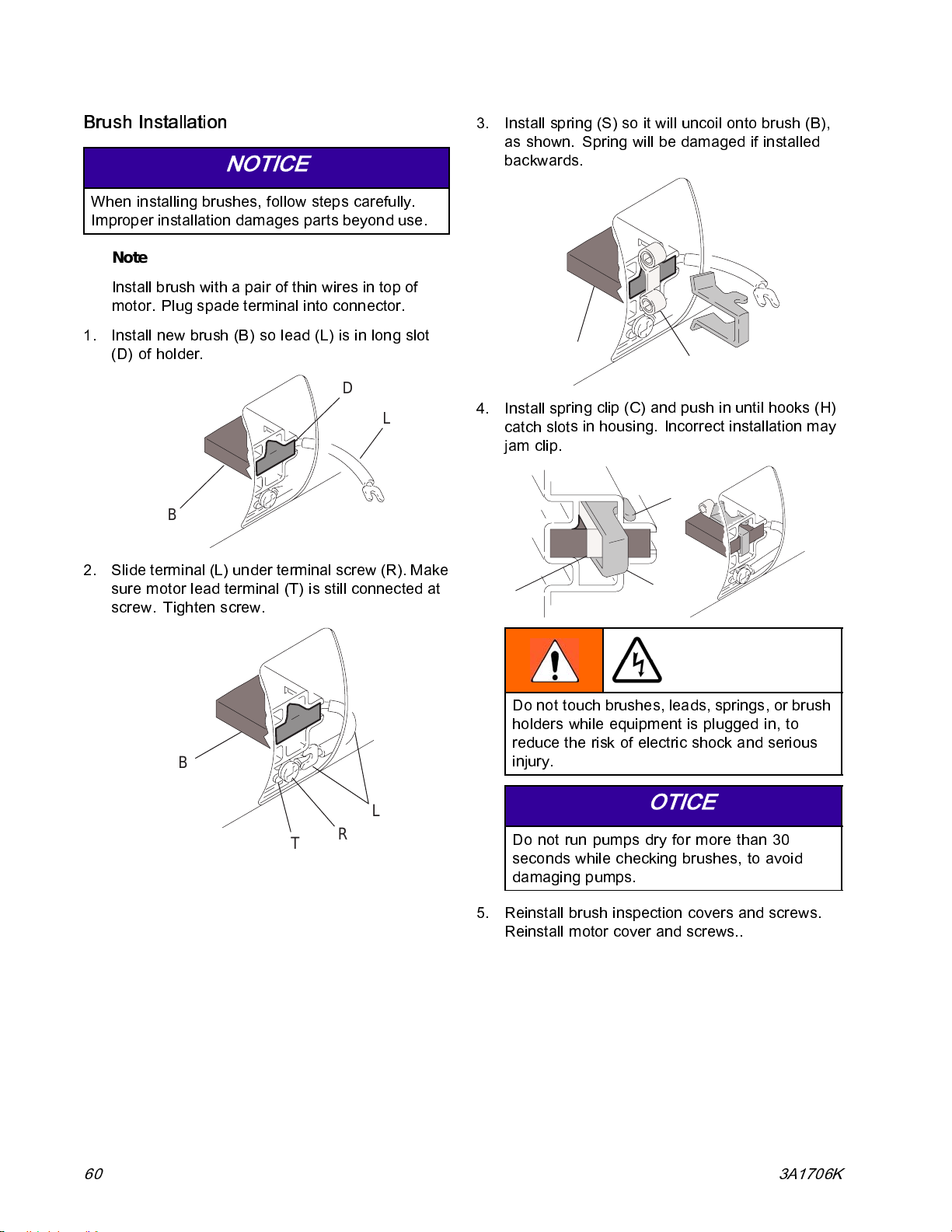
Repair
Brush Installation
NOTICE
When i ns tal li ng brushes, follow steps carefully.
Improper installati on damages parts beyond use .
Note
Install brush with a pair of thin wires in top of
motor. Plug spade terminal into connector.
1. Install new brush (B) so lead (L) is in long slot
(D) of holder.
D
L
B
2. Slide terminal (L) under terminal screw (R). Make
sure motor lead terminal (T) is still connected at
screw. Tighten screw.
3. Install spring (S) so it will uncoil onto brush (B),
as shown. Spring will be damaged if installed
backwards.
4. Install sp
catch slot
jam clip.
S
B
ring clip (C) and push in until hooks (H)
s in housing. Incorrect installation may
S
H
C
Do not touch brushes, leads, springs, or brush
holders while equipment is plugged in, to
reduce the risk of electric shock and serious
B
L
T
R
injury.
NOTICE
Do not
secon
damag
5. Reinstall brush inspection covers and screws.
Reinstall motor cover and screws..
run pumps dry for more than 30
dswhilecheckingbrushes,toavoid
ing pumps.
60 3A1706K
Page 61
Repair
6. Reinstall fan assembly and plates.
7. Test brushes with both pump pins (F)
disconnected. See Fi g. 12, page 56.
a. Start engine.
b. Activate system.
c. Press circulate
d. Press
e. Select J 1 (jog mode). Slowly increase jog
setting to J 6. Inspect brush and commutator
contact area for excessive arcing. Arcs
should not “trail” or ci rcle around commutator
surface. Run motor for 20-30 min at J 6 to
seat brushes.
to start motor.
to enter jog mode.
Repair Electric Motor
Removal
NOTICE
5. Disconnect brushwear/over temperature cable
from port #10 on MCM. Cut tie wraps around
harness to remove cable.
6. Remove four screws (273) holding motor (301) to
bracket. Lift motor off unit.
Installation
1. Place motor on unit. Thread motor
cables into conduit as before. See
Electrical Schematics, page 134.
2. Fasten motor with screws (273) until screws
are fully threaded in mounting bracket. Do not
tighten screws until drive housing and pumps are
connected to the motor.
Note
If necessary, loosen screws (273) to
align the motor (301) with side brackets.
3. Install drive housing and pump assemblies, see
Installation, page 58.
4. Install screws (326) and washers (314). Tighten
screws (273).
Be careful not to drop or damage the motor. The
motor is heavy and may require two people to lift.
1. Remove drive housing and pump assemblies.
See Repair Drive Housing, page 56.
2. Disconnect electric motor (301) power cable from
port #13 on the MCM.
3. Remove two screws (299) and motor fan
assembly. Rest the motor fan assembly behi nd
the motor without straining the fan power cabl e.
See Fig. 20, page 65.
4. Remove screws (326) and washers (314). Test
brushes with both pump pins (F) disconnected.
See Fig. 14, page 57.
5. Route motor (301) power cord from motor
through conduit and connect to port #13 on
MCM. Route brushwear/over temperature cable
up from motor and connect to port #10 on MCM.
Insert cables in conduit and use tie wraps to
secure the conduit together and the pallet.
6. Connect motor fan assembly to motor (301). See
Fig. 20, page 62.
7. Install front bracket.
8. Install drive housing covers and motor cover.
9. Return to service.
3A1706K 61
Page 62
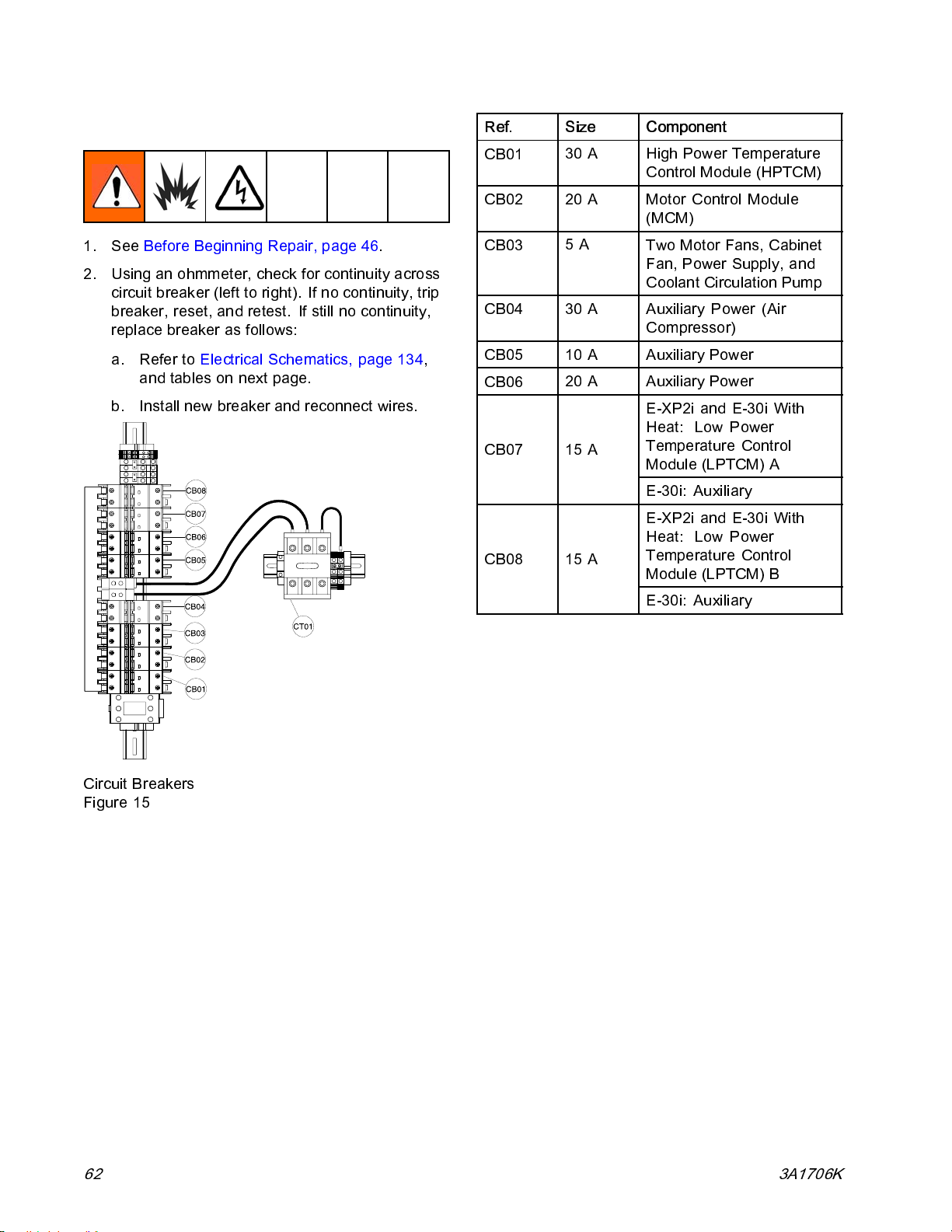
Repair
Repair Circuit Breaker Module
1. See Before Beginning Repair, page 46.
2. Using an ohmmeter, check for continuity across
circuit breaker (left to right). If no continuity, trip
breaker, reset, and retest. If still no continuity,
replace breaker as follows:
a. Refer to Electrical Schematics, page 134,
and tables on next page.
b. Install new breaker and reconnect wires.
Ref. Size Component
CB01
CB02
CB03
CB04 30 A Auxiliary Power (Air
CB05
CB06
CB07 15 A
CB08
30 A High Power Temperature
Control Module (HPTCM )
20 A
5A
10 A Auxiliary Power
20 A Auxiliary Power
15 A
Motor Control Module
(MCM)
Two Motor Fans, Cabinet
Fan, Power Supply, and
Coolant Circulation Pump
Compressor)
E-XP2i and E-30i With
Heat: Low Power
Temperature Control
Module (LPTCM) A
E-30i: Auxiliary
E-XP2i and E-30i With
Heat: Low Power
Temperature Control
Module (LPTCM) B
Circuit Breakers
Figure 15
E-30i: Auxiliary
62 3A1706K
Page 63
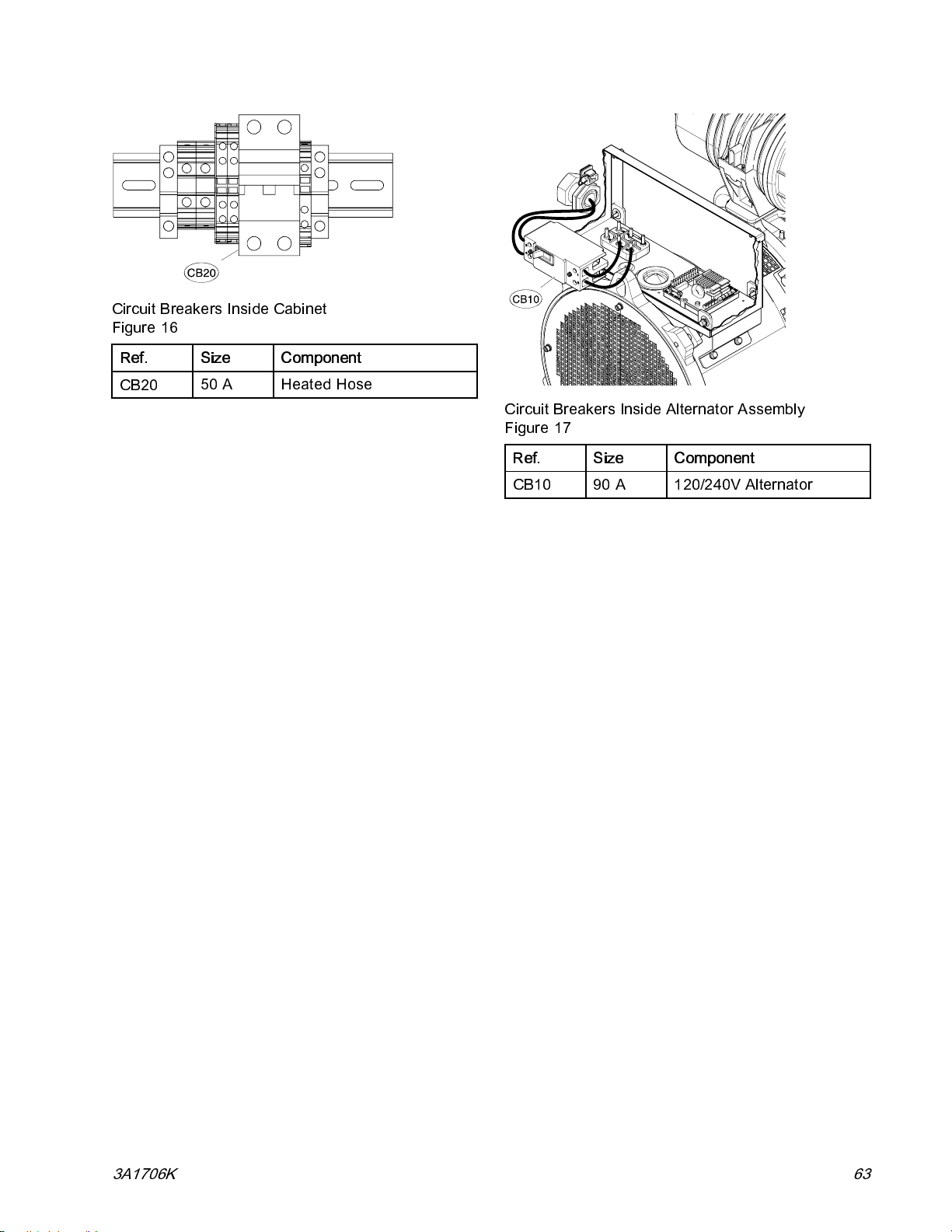
Circuit Breakers Inside Cabinet
Figure 16
Ref. Size Component
Repair
CB20
50 A Heated Hose
Circuit Breakers Inside Alternator Assembly
Figure 17
Ref. Size Component
CB10
90 A 120/240V Alternator
3A1706K 63
Page 64

Repair
Replace Relays and Fuses
Replace Load Center Relays and Fuses
1. Disconnect the negative lug from the negative
post ofthebattery. See Replace Battery, page 81.
2. Remove the bad relay or fuse from the load
center (242) and install a new relay or fuse. See
Fig. 18.
3. Connect battery cable. See
Replace Battery, page 81.
Relay and Fuse Identification Table
See Load Center Wiring Diagram, page 143.
Repair
Kit
24L958
24L959
Ref
K1
K2
K3
K4
F3 FAN-ATO - 30A
F4 PWR-ATO - 20A
Component
Fuel Relay
Starter Relay
Glow Plug Relay
Fan Relay
Fuse for load center
relay K4 and radiator
fan.
Fuse for load center
relays K1, K2, K3
and their related
components; Engine
Control Module
power; and coolant
valve control.
Load Center Relay and Fuse Identification
Figure 18
Replace Load Center
NOTICE
Before handling board, put on a static conductive
wrist strap to protect against static discharge which
can damage board. Follow instructions provided
with wrist strap.
1. Perform Shutdown, page 49.
2. Disconnect the negative lug from the negative
post of the battery. See R epl ac e Battery, page 81
3. Disconnect all connectors. See
Load Center Wiring Diagram, page 143
4. Remove four bolts (250) and load center (242).
5. Install new load center (242) and
reconnect all connectors. See
Load Center Wiring Diagram, page 143
6. Connect battery cable. See
Replace Battery, page 81.
64 3A1706K
Page 65
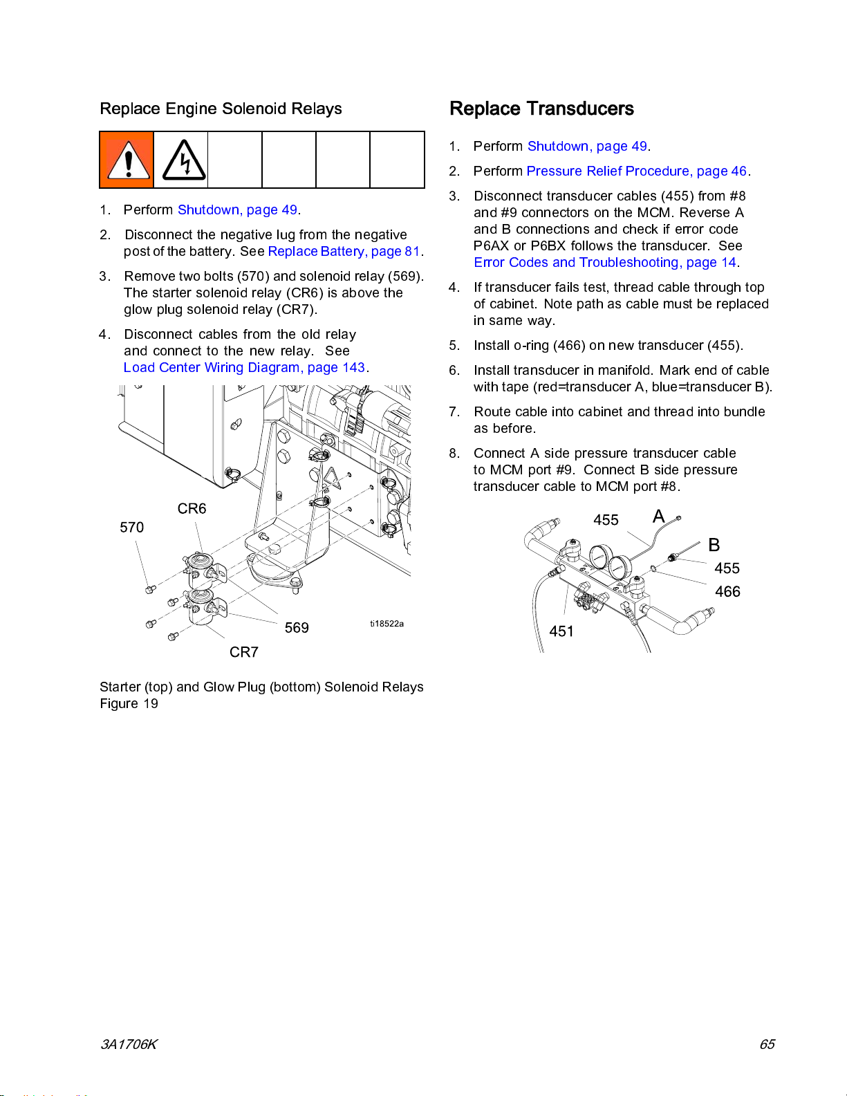
Repair
Replace Engine Solenoid Relays
1. Perform Shutdown, page 49.
2. Disconnect the negative lug from the negative
post of the battery. See Replace Battery, page81.
3. Remove two bolts (570) and solenoid relay (569).
The starter solenoid relay (CR6) is above the
glow plug solenoid relay (CR7).
4. Disconnect cables from the old relay
and conne ct to the new relay. See
Load Center Wiring Diagram, page 143.
Replace Transducers
1. Perform Shutdown, page 49.
2. Perform Pressure Relief Procedure, page 46.
3. Disconnect transducer cables (455) from # 8
and #9 connectors on the MCM. Reverse A
and B connections and check if error code
P6AX or P6BX follows the transducer. See
Error Codes and Troubleshooting, page 14.
4. If transducer fails test, thread cable through top
of cabinet. Note path as cable must be replaced
in same way.
5. Install o-ring (466) on new transducer (455).
6. Install transducer in manifold. Mark e nd of cable
with tape (red=transducer A, blue=transduc er B).
7. Route cable into cabinet and thread into bundle
as before.
8. Connect A side pressure transducer cable
to MCM port #9. Connect B side pressure
transducer cable to MCM port #8.
Starter (top) and Gl ow Plug (bottom) Sole noi d Relay s
Figure 19
3A1706K 65
Page 66
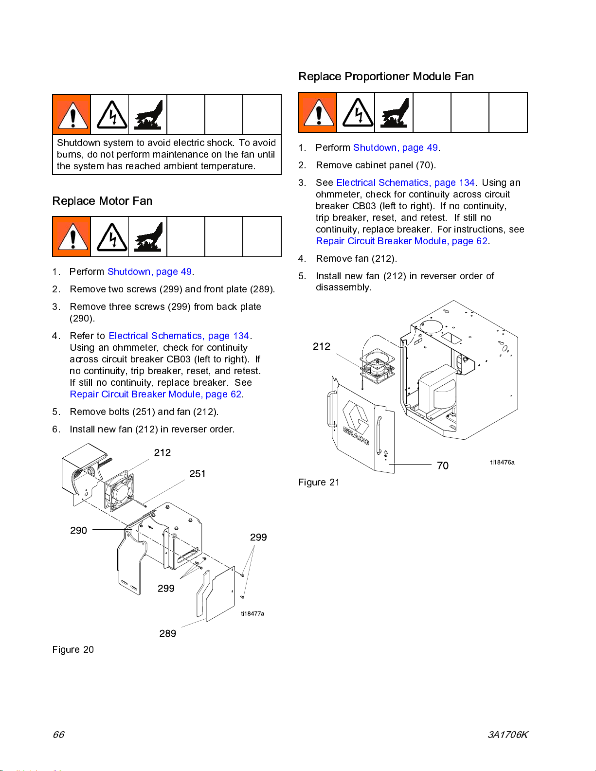
Repair
Replace Fans
Shutdown system to avoid electric shock. To avoid
burns, do not perform maintenance on the fan until
the system ha s reached ambient temperature.
Replace Motor Fan
1. Perform Shutdown, page 49.
2. Remove two screws (299) and front plate (289).
3. Remove three screws (299) from back plate
(290).
4. Refer to Electrical Schematics, page 134.
Using an ohmmeter, check for continuity
across circuit breaker CB03 (left to right). If
no continuity, trip breaker, reset, and retest.
If still no continuity, replace breaker. See
Repair Circuit Breaker Module, page 62.
Replace Proportioner Module Fan
1. Perform Shutdown, page 49.
2. Remove cabinet panel (70).
3. See Electrical Schemat ics, page 134.Usingan
ohmmeter, check for continuity across circuit
breaker CB03 (left to righ t). If no continuity ,
trip breaker, reset, and retest. If still no
continuity, replace breaker. For instructions, see
Repair Circuit Breaker Module, page 62.
4. Remove fan (212).
5. Install new fan (212) in reverser order of
disassembly.
5. Remove bolts (251) and fan (212).
6. Install new fan (212) in reverser order.
Figure 20
Figure 21
66 3A1706K
Page 67
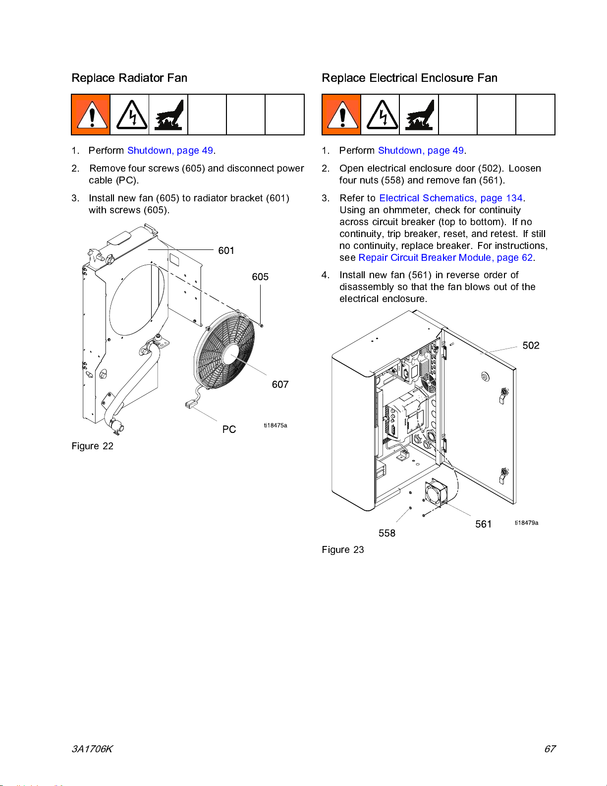
Repair
Replace Radiator Fan
1. Perform Shutdown, page 49.
2. Remove four screws (605) and disconnect power
cable (PC).
3. Install new fan (605) to radiator bracket (601)
with screws (605).
Replace Electrical Enclosure Fan
1. Perform Shutdown, page 49.
2. Open electrical enclosure door (502). Loosen
four nuts (558) and remove fan (56 1).
3. Refer to Electrical Schematics, page 134.
Using an ohmmeter, check for continuity
across circuit breaker (top to bottom). If no
continuity, trip breaker, res et, and retest. If still
no continuity, replace breaker. For instructions,
see Repair Circuit Breaker Module, page 62.
4. Install new fan (561) in reverse order of
disassembly so that the fan blows out of the
electrical enclosure.
Figure 22
Figure 23
3A1706K 67
Page 68
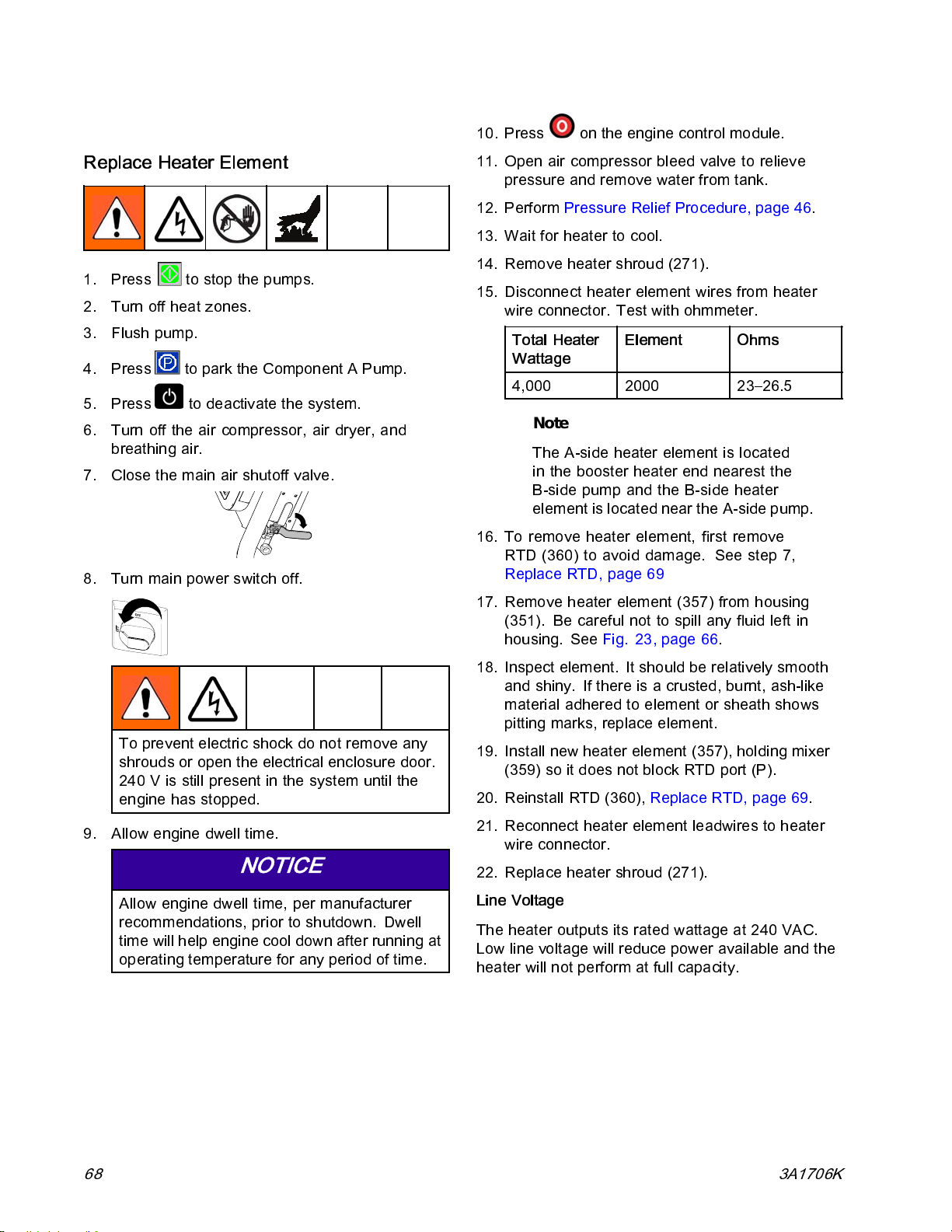
Repair
Repair Booster Heater
Replace Heater Element
1. Press to stop the pumps.
2. Turn off heat zones.
3. Flush pump.
4. Press
5. Press
6. Tu rn off the air compre ss or, air dryer, and
breathing air.
7. Close the main air shutoff valve.
8. Turn main power switch off.
to park the Component A Pump.
to deactivat e the system.
10. Press on the engine control module.
11. Open air compressor bleed valve to relieve
pressure and remove water from tank.
12. Perform Pressure Relief Procedure, page 46.
13. Wait for heater to cool.
14. Remove heater shroud (271).
15. Disconnect heater element wires from heater
wire connector. Test with ohmmeter.
Total Heater
Wattage
4,000 2000 23–26.5
Note
The A-side heater element is located
in the booster heater end nearest the
B-side pump and the B-side heater
element is located near the A-side pump.
16. To remove heater element, first remove
RTD (360) to avoid damage. See step 7,
Replace RTD, page 69
17. Remove heater element (357) from housing
(351). Be careful not to spill any fluid left in
housing. See Fig. 23, page 66.
Element Ohms
To prevent electric shock do not remove any
shrouds or open the electrical enc losure door.
240 V is stil l present in the sys tem until th e
engine has stopped.
9. Allow engine dwell time.
NOTICE
Allow engine dwell time, per manufacturer
recommendations, prior to shutdown. Dwell
time will help engine cool down after running at
operating temperature for any period of time.
18. Inspect element. It should be relatively smooth
and shiny. If there is a crusted, burnt, ash-like
material adhered to element or sheath shows
pitting marks, replace element.
19. Install new heater element (357), holding mixer
(359) so it does not block RTD port (P).
20. Reinstall RTD (360), Replace RTD, page 69.
21. Reconnect heater element leadwires to heater
wire connector.
22. Replace heater shroud (271).
Line Voltage
The heater outputs its rated wattage at 240 VAC.
Low line voltage will reduce power available and the
heater will not perform at full capacity.
68 3A1706K
Page 69
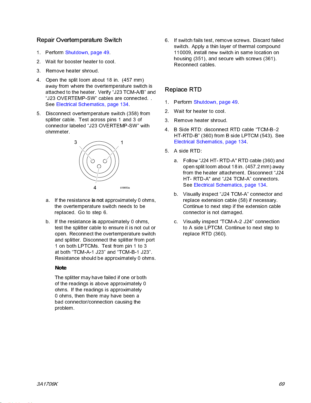
Repair
Repair Overtemperature Switch
1. Perform Shutdown, page 49.
2. Wait for booster heater to cool.
3. Remove heater shroud.
4. Open the split loom about 18 in. (457 mm)
away from where the overtemperature switch is
attached to the heater. Verify “J23 TCM-A/B” and
“J23 OVERTEMP-SW” cables are connected. .
See Electrical Schematics, page 134.
5. Disconnect overtemperature switch (358) from
splitter cable. Test across pins 1 and 3 of
connector labeled “J23 OVERTEMP-SW” with
ohmmeter.
6. If switch fails test, remove screws. Discard failed
switch. Apply a thin layer of thermal compound
110009, install new switch in same location on
housing (351), and secure with screws (361).
Reconnect cables.
Replace RTD
1. Perform Shutdown, page 49.
2. Wait for heater to cool.
3. Remove heater shroud.
4. B Side RTD: disconnect RTD cable “TCM-B–2
HT-RTD-B” (360) from B side LPTCM (543). See
Electrical Schematics, page 134.
5. A side RTD:
a. Follow “J24 HT- RTD-A" RTD cable (360) and
open split loom about18in. (457.2 mm) away
from the heater attachment. Disconnect “J24
HT- RTD-A" and “J24 TCM-A” connectors.
See Electrical Schematics, page 134.
a. If the resistance
the overtemperature switch needs to be
replaced. Go to step 6.
b. If the resistanceisapproximately 0 ohms,
test the splitter cable to ensure it is not cut or
open. Reconnect the overtemperature switch
and splitter. Disconnect the splitter from port
1onbothLPTCMs. Testfrompin1to3
at both “TCM-A-1 J23” and “TCM-B-1 J23”.
Resistance should be approximately 0 ohms.
Note
The splitter may have failed if one or both
of the readings is above approximately 0
ohms. If the readings is approximately
0 ohms, then there may have been a
bad connector/connection causing the
problem.
is not
approximately 0 ohms,
b. Visually inspect “J24 TCM-A” connector and
replace e xte ns ion cable (58) if necessa ry.
Continue to next step if the extension cable
connector is not damaged.
c. Visually inspect “TCM-A-2 J24” connection
toAsideLPTCM.Continuetonextstepto
replace RTD (360).
3A1706K 69
Page 70
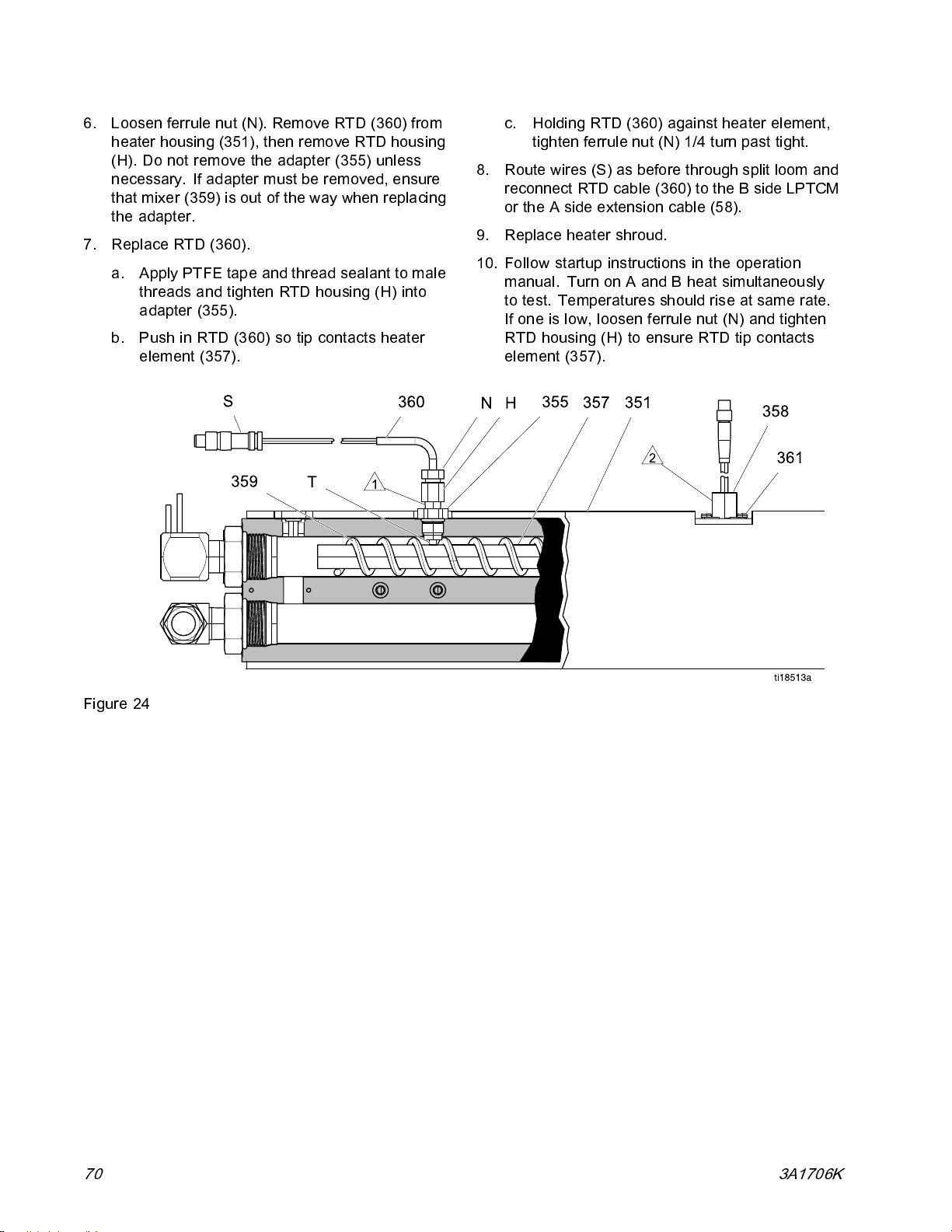
Repair
6. Loosen ferrule nut (N). Remove RTD (360) from
heater housing (351), then remove RTD housing
(H). Do not remove the adapter (35 5) unless
necessary. If adapter must be removed, ensure
that mixer (359) is out of the way when replacing
the adapter.
7. Replace RTD (360).
a. Apply PTFE tape and thread sealant to male
threads and tighten RTD housing (H) into
adapter (355).
b. Push in RTD (360) so tip contacts heater
element (357).
c. Holding RTD (360) against heater element,
tighten ferrule nut (N) 1/4 turn past tight.
8. Route wires (S) as before through split loom and
reconnect RTD cable (360) to the B side LPTCM
or the A side extension cable (58).
9. Replace heater shroud.
10. Follow startup instructions in the operation
manual. Turn on A and B heat simultaneously
totest.Temperaturesshouldriseatsamerate.
If one is low, lo osen ferrule nut (N) and tighten
RTD housing (H) to ensure RTD tip contacts
element (357).
Figure 24
70 3A1706K
Page 71
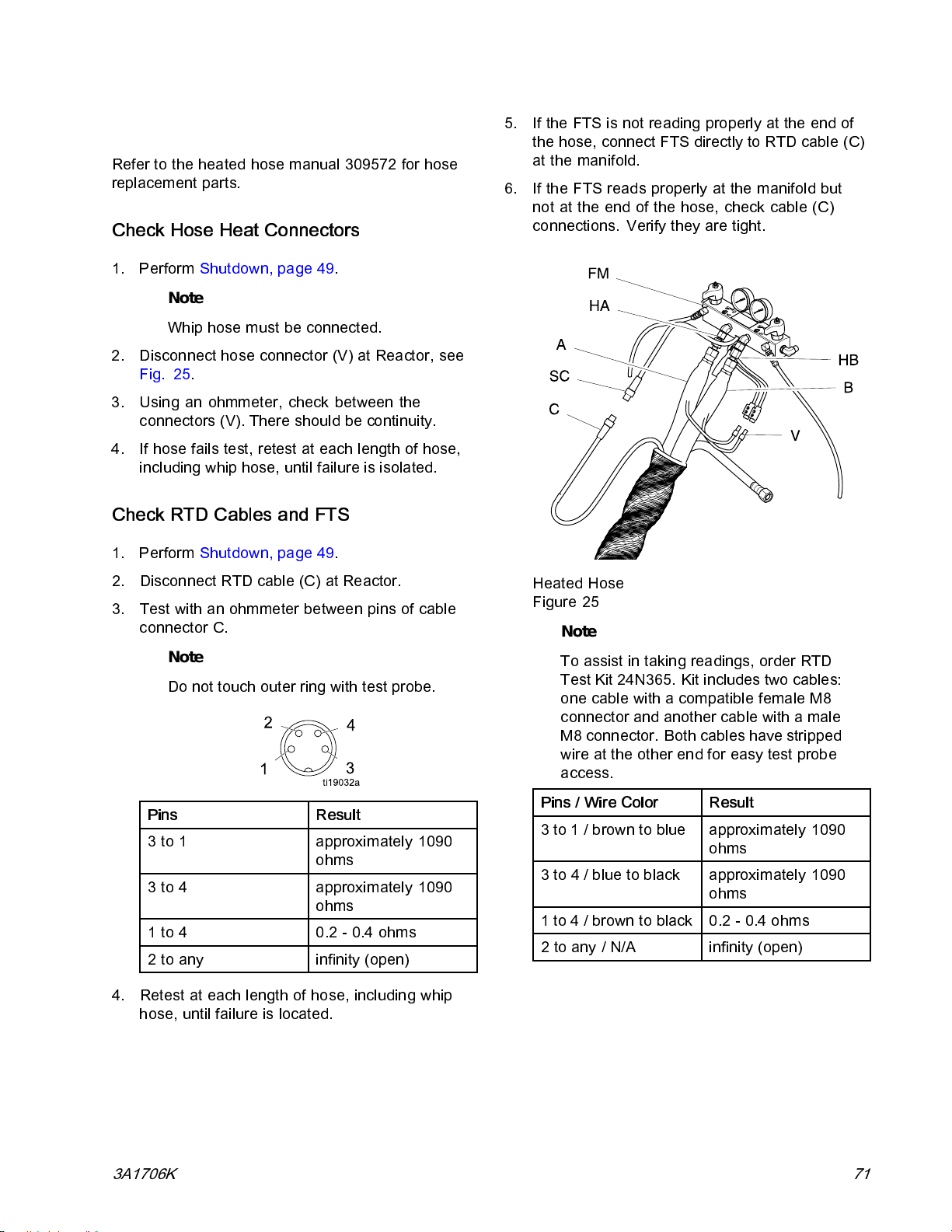
Repair
Repair Heated Hose
Refer to the heated hose manual 309572 for hose
replacement parts.
Check Hose Heat Connectors
1. Perform Shutdown, page 49.
Note
Whip hose must be connected.
2. Disconnect hose connector (V) at Reactor, see
Fig. 25.
3. Using an ohmmeter, check between the
connectors (V). Th ere should be continuity .
4. If hose fails test, retest at each length of hose,
including whip hose, until failure is isolated.
Check RTD Cables and FTS
1. Perform Shutdown, page 49.
5. If the FTS is not reading properly at the end of
the hose, connect FTS directly to RTD cable (C)
at the manifold.
6. If the FTS reads properly at the manifold but
not at the end o f the hose, check cable (C)
connections. Verify they are tight.
2. Disconnect RTD cable (C) at Reactor.
3. Test with an ohmmeter between pins of cable
connector C.
Note
Do not touch outer ring with test probe.
Pins Result
3 to 1 approximately 1090
ohms
3 to 4 approximately 1090
ohms
1 to 4 0.2 - 0.4 ohms
2toany
4. Retest at each length of hose, including whip
hose, until failure is located.
infinity (open)
Heated Hose
Figure 25
Note
To assist in taking readings, order RTD
Test Kit 24N365. Kit includes two cables:
one cable with a compatible female M8
connector and another cable with a male
M8 connector. Both cables have stripped
wire at the other end for easy test probe
access.
Pins / Wire Color
3 to 1 / brown to blue approximately 1090
/ blue to black
3to4
1 to 4 / brown to black 0.2 - 0.4 ohms
2toany/N/A
Result
ohms
oximately 1090
appr
ohms
infinity (open)
3A1706K
71
Page 72
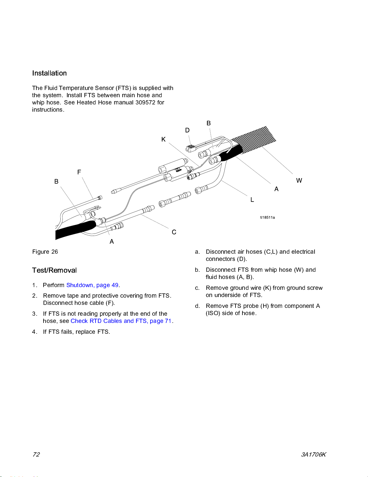
Repair
Repair Fluid Temperature Sensor (FTS)
Installation
The Fluid Temperature Sensor (FTS) is supplied with
the s y ste m. Install FTS between main hose and
whip hose. See Heated Hose manual 309572 for
instructions.
Figure 26
Test/Removal
1. Perform Shutdown, page 49.
2. Remove tape and protective covering from FTS .
Disconnect hose cable (F).
3. If FTS is not reading properly at the end of the
hose, see Check RTD Cables and FTS, page 71.
4. If FTS fails, replace FTS.
a. Disconnect air hoses (C,L) and electrical
connectors (D).
b. Disconnect FTS from whip hose (W) and
fluid hoses (A, B).
c. Remove ground wire (K) from ground screw
on underside of FTS.
d. Remove FTS probe (H) from component A
(ISO) side of hose.
72
3A1706K
Page 73
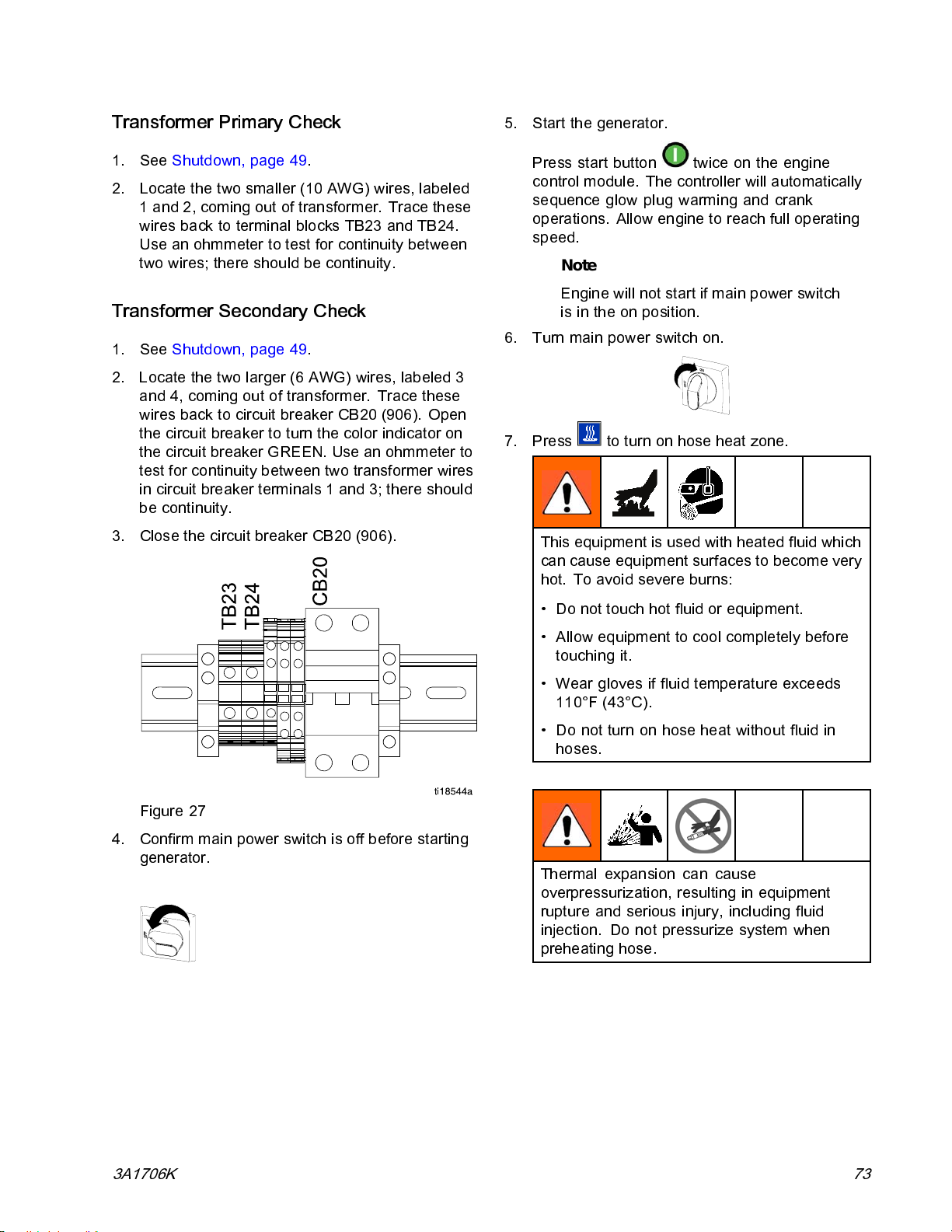
Repair
Transformer Primary Check
1. See Shutdown, page 49.
2. Locate the two smaller (10 AWG) wires, labeled
1 and 2, coming out of transformer. Trace these
wires back to terminal blocks TB23 and TB24.
Use an ohmmeter to test for continuity between
two wires; there should be c onti nu ity.
Transformer Secondary Check
1. See Shutdown, page 49.
2. Locate the two larger (6 AWG) wires, labeled 3
and 4, coming out of transformer. Trace these
wires back to circuit breaker CB20 (906). Open
the circuit breaker to turn the color indicator on
the circuit breaker GREEN. Use an ohmmeter to
test for continuity between two transformer wires
in circuit breaker terminals 1 and 3; there should
be co nti nui ty .
3. Close the circuit breaker C B20 (906).
5. Start the generator.
Press start button
control module. The controller will automatically
sequence glow plug warming and crank
operations. Allow engine to reach full operating
speed.
Note
Engine will not start if main power switch
is in the on position.
6. Turn main power switch on.
7. Press to turn on hose heat zone.
Thisequipmentisusedwithheatedfluidwhich
can cause equipment surfaces to bec ome very
hot. To avoid severe burns:
twiceontheengine
Figure 27
4. Confirm main power switch is off before starting
generator.
• Do not touch hot fluid or equipment.
• Allow equipment to cool completely before
touching it.
• Wear gloves if fluid temperature exceeds
110°F (43°C).
• Do not turn on hose heat witho ut fluid in
hoses.
Thermal expansion can cause
overpressurization, resulting in equipment
rupture and serious injury, including fluid
injection. Do not pressurize system when
preheating hose.
3A1706K 73
Page 74

Repair
8. To verify voltage on the secondary leads of the
transformer, measure between the terminals 2
and 4 on CB20. This will verify the circuit breaker
is working properly.
Model
310 ft 90 Vac*
210 ft 62 Vac*
* For 240 Vac line voltage.
9. See the Diagnostic Run Screen on the ADM. The
Diagnostic Run Screen displays the incoming
(240 Vac) to the HPTCM (TCM-H) “Hose Voltage”
and the hose current. The diagnostic screen will
show if the circuit breaker has been tripped for
the incoming power to the HPTCM.
Secondary Voltage
2. Perform Flushing, page 47.
3. Perform Shutdown, page 49.
4. Perform Drain Coolant, page 50.
5.
For proportioner heat exchangers:
a. Remove fuel tank. See
Remove Fuel Tank, page 81.
b. Disconnect both RTD con nectors (284). See
Replace Proportioner RTD, page 76.
c. Disconnect A and B material lines from
swivel fittings (297).
Replace Transformer
1. Perform Shutdown, page 49.
2. Open Reactor cabinet.
3. Remove bolts holding transformer (226) to
cabinet floor.
4. Disconnect the transformer wires. See
Reactor Cabinet Wiring Diagram, page 142
5. Remove transformer (226) f rom cabinet.
6. Install new transformer (226) in reverse orde r.
Replace Heat Exchangers
1. If a wall is installed between the generator and
the proportioner, remove the proportioner from
the pallet. See Remove Proportioner, page 88.
Proportioner Heat Exchangers
Figure 28
d. Disconnect hose clamps (37, 239) from heat
exchanger assembly (241).
e. Remove four nuts (249) and the heat
exchanger assembly (241). Pull heat
exchanger assembly out of coolant hoses.
f. Install a new heat exchanger assembly
(241) by following the removal steps in
reverse order. Orient control valves as
shown. Continue to next step to remove heat
exchangers (802) or (803).
74
3A1706K
Page 75
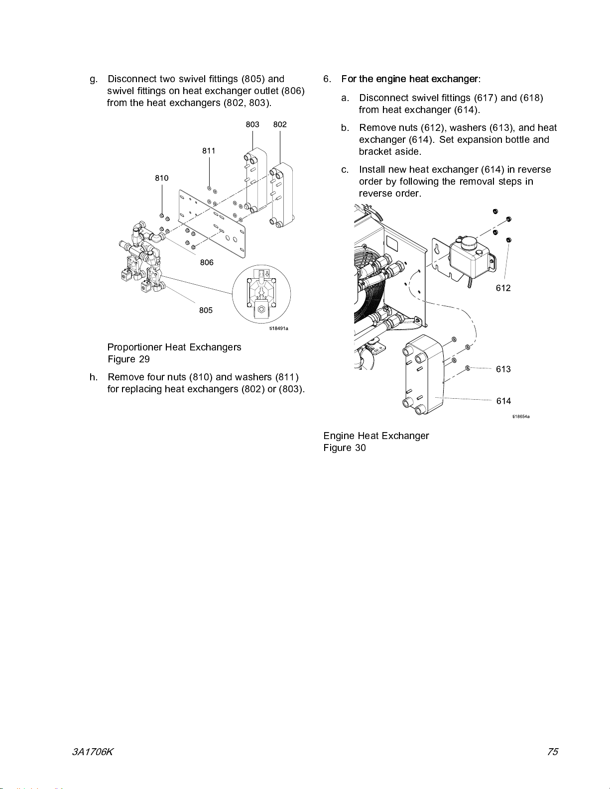
g. Disconnect two swivel fittings (805) and
swivel fittings on heat exchanger outlet (806)
from the heat exchangers (802, 803).
6.
For the engine heat exchanger:
a. Disconnect swivel fittings (617) and (618)
from heat exchanger (614).
b. Remove nuts (612), washers (613), and heat
exchanger (614). Set expansion bottle and
bracket aside.
c. Install new hea t exchanger (614) in reverse
order by following the removal steps in
reverse order.
Repair
Proportioner Heat Exchangers
Figure 29
h. Remove four nuts (810) and washers (811)
for replacing heat exchangers (802) or (803).
Engine Heat Exchanger
Figure 30
3A1706K 75
Page 76
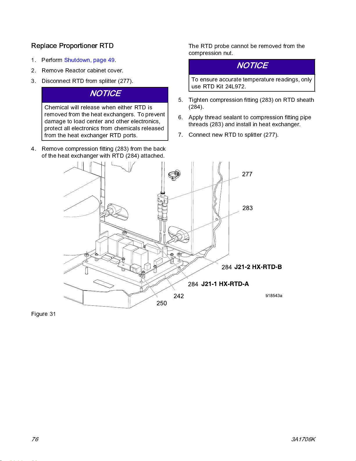
Repair
Replace Proportioner RTD
1. Perform Shutdown, page 49.
2. Remove Reactor cabinet cover.
3. Disconnect RTD from splitter (277).
NOTICE
Chemical will release when either RTD is
removed from the heat exchangers. To prevent
damage to load center and other electronics,
protect all electronics from chemicals released
from the heat exchanger RTD ports.
4. Remove compression fitting (283) from the back
of the heat exchanger with RTD (284) attached.
The RTD probe cannot be removed from the
compression nut.
NOTICE
To ensure accurate temperature readings, only
use RTD Kit 24L972.
5. Tighten compression fitting (283) on RTD sheath
(284).
6. Apply thread sealant to compression fitting pipe
threads (283) and install in heat exchanger.
7. Connect new RTD to splitter (277).
Figure 31
76 3A1706K
Page 77
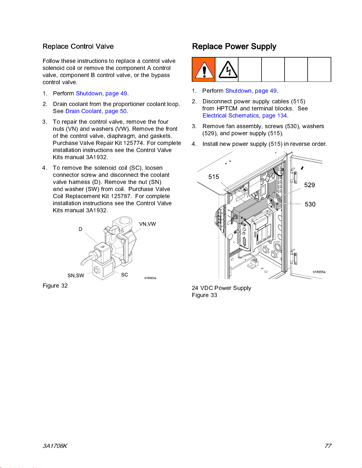
Repair
Replace Control Valve
Follow these instructions to replace a control valve
solenoid coil or remove the component A control
valve, component B control valve, or the by pas s
control valve.
1. Perform Shutdown, page 49.
2. Drain coolant from the proportioner coolant loop.
See Drain Coolant, page 50.
3. To repair the control valve, remove the four
nuts (VN) and washers (VW). Remove the front
of the control valve, diaphragm, and gaskets.
Purchase Valve Repair Kit 125774. For com plete
installation instructions see the Control Valve
Kits manual 3A1932.
4. To remove the solenoid coil (SC), loosen
connector screw and disconnect the coolant
valve harness (D). Remove the nut (SN)
and washer (SW) from coil. Purchase Valve
Coil Replacement Kit 125787. For complete
installation instructions see the Control Valve
Kits manual 3A1932.
Replace Power Supply
1. Perform Shutdown, page 49.
2. Disconnect power supply cables (515)
from HPTCM and terminal blocks. See
Electrical Schematics, page 134.
3. Rem ov e fan assembly , screws (530), washers
(529), and power supply (515).
4. Install new power supply (515) in reverse order.
Figure 32
3A1706K
24 VDC Power Supply
Figure 33
77
Page 78

Repair
Replace Circulation Pump
Do not perform maintenance on the coolant s ystem
until the coolant system has reached ambient
temperature.
1. Perform Shutdown, page 49.
2. Perform Drain Coolant, page 50.
3. If a wall is installed and the circulation pump can
not be accessed, remove the proportioner. See
Remove Proportioner, page 88.
4. Disconnect pump fittings (234) from swivel fitting
(275).
5. Remove pump cover (C).
6. Press in tabs to disconnect power wires (W).
7. Remove four outside nuts (254). Hold on to the
pump flanges (234) and remove the circulation
pump (233). Remove four inside nuts (254) to
remove flanges from the pump.
8. Place o-rings, supplied with the new circulation
pump (233), between the pump and the flange
fittings (234). Insert screws (255) through the
pump and flange fittings (234) and tighten four
nuts on screws (255).
9. Place circulation pump (233) on brackets (223)
so that coolant will flow towards the sight glass.
Install four nuts (254) on screws (255).
10. Connect power wires to pump and replace cover.
See Reactor Cabinet Wiring Diagram, page 142.
11. Connect flange fittings (234) to swivel on the
elbow flange fitting (234) and fitting (275).
Figure 34
78 3A1706K
Page 79
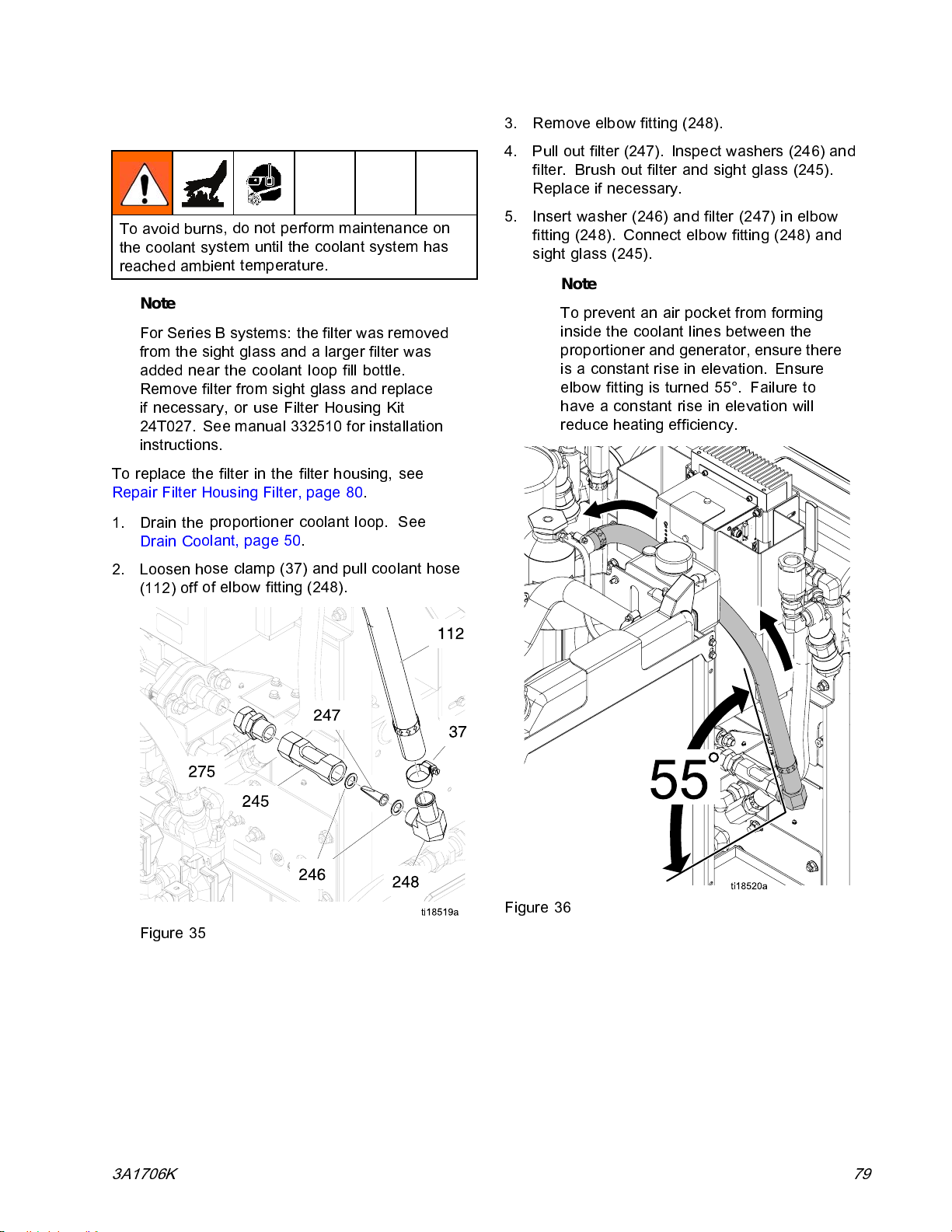
Repair
Repair Sight Glass Filter
To avoid burn
the coolant s
reached ambi
Note
For Series B systems: the filter was remov ed
from the sight glass and a larger filter was
added near the coolant loop fill bottle.
Remove filter from sight glass and replace
if necessary, or use Filter Housing Kit
24T027. See manual 332510 for installation
instructions.
To replace the filter in the filter housing, see
Repair Filter Housing Filter, page 80.
1. Drain the
Drain Co
2. Loosen h
(112) of
s, do not perform maintenance on
ystem until the coolant system has
ent temperature.
proportioner coolant loop. See
olant, page 50.
ose clamp (37) and pull coolant hose
f of elbow fitting (248).
3. Remove elbow fitting (248).
4. Pull out filter (247). Inspect washers (246) and
filter. Brush out filter and sight glass (245).
Replace if necessary.
5. Insert washer (246) and filter (247) in elbow
fitting (248). Connect elbow fitting (248) and
sight glass (245).
Note
To prevent an air pocket from forming
inside the coolant lines b etween the
proportioner and generator, ensure there
is a constant rise in elevation. Ensure
elbow fitting is turned 55°. Failure to
have a constant rise in elevation will
reduce heati ng efficiency.
Figure 36
Figure 35
3A1706K 79
Page 80
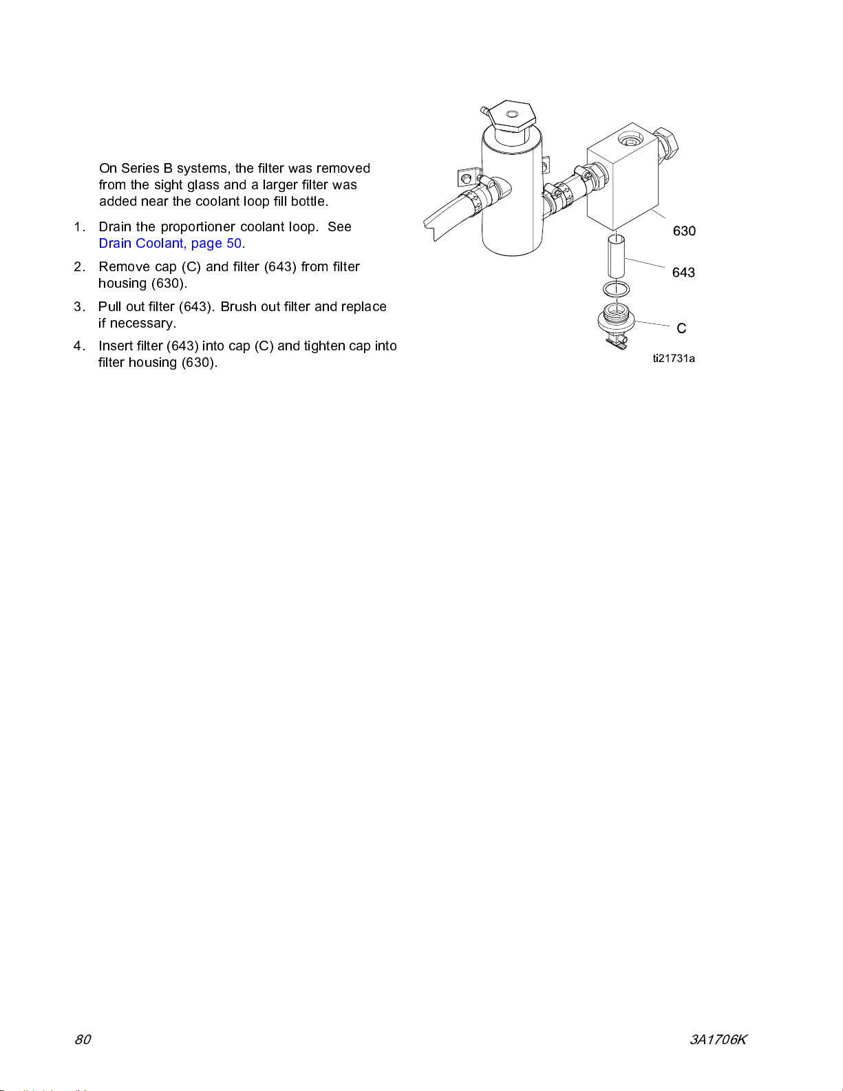
Repair
Repair Filter Housing Filter
Note
On Series B systems, the filter was rem ov ed
from the sight glass and a larger filter was
added near the coolant loop fill bottle.
1. Drain the proportioner coolant loop. See
Drain Coolant, page 50.
2. Remove cap (C) and filter (643) from filter
housing (630).
3. Pull out filter (643). Brush out filter and replace
if ne ce ss ary .
4. Insert filter (643) into cap (C) and tighten cap into
filter housing (630).
80 3A1706K
Page 81
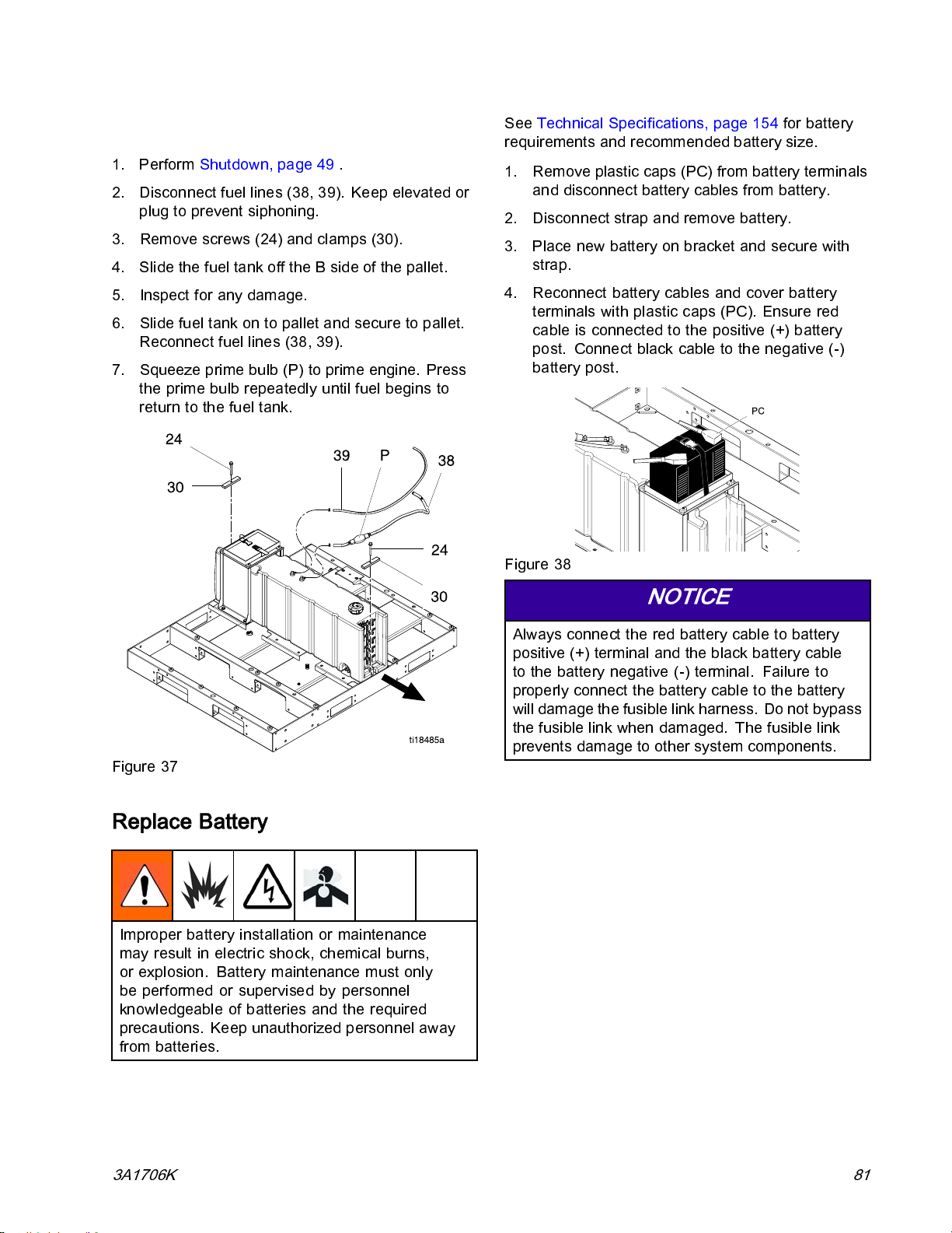
Repair
Remove Fuel Tank
1. Perform Shutdown, page 49 .
2. Disconnect fuel lines (38, 39). Keep elevated or
plug to prevent siphoni ng.
3. Remove screws (24) and clamps (30).
4. Slide the fuel tank off the B side of the pall et.
5. Inspect for any damage.
6. Slidefueltankontopalletandsecuretopallet.
Reconnect fuel lines (38, 39).
7. Squeeze prime bulb (P) to prime engine. Press
the prime bulb repeatedly until fuel begins to
return to the fuel tank.
See Technical Specifications, page 154 for battery
requirements and recommended battery size.
1. Remove plastic caps (PC) from battery terminals
and disconnect battery cables from battery.
2. Disconnect strap and remove battery.
3. Place new battery on bracket and secure with
strap.
4. Reconnect battery cables and cover battery
terminals with plastic caps (PC). Ensure red
cable is connected to the positive (+) battery
post. Connect black cable to the negative (-)
battery post.
Figure 38
Figure 37
Replace Battery
Improper battery installation or maintenance
may result in electric shock, chemical burns,
or explosion. Battery maintenance must only
be performed or supervised by personnel
knowledgeable of batteries and the required
precautions. Keep unauthorized personnel away
from batteries.
NOTICE
Always connect the red battery cable to ba ttery
positive (+) terminal and the black battery cable
to the battery negative (-) terminal. Failure to
properly connect the battery cable to the battery
will d amage the fusible link harness. Do not bypass
the fusible link when damage d. The fusible link
prevents damage to other system component s.
3A1706K 81
Page 82
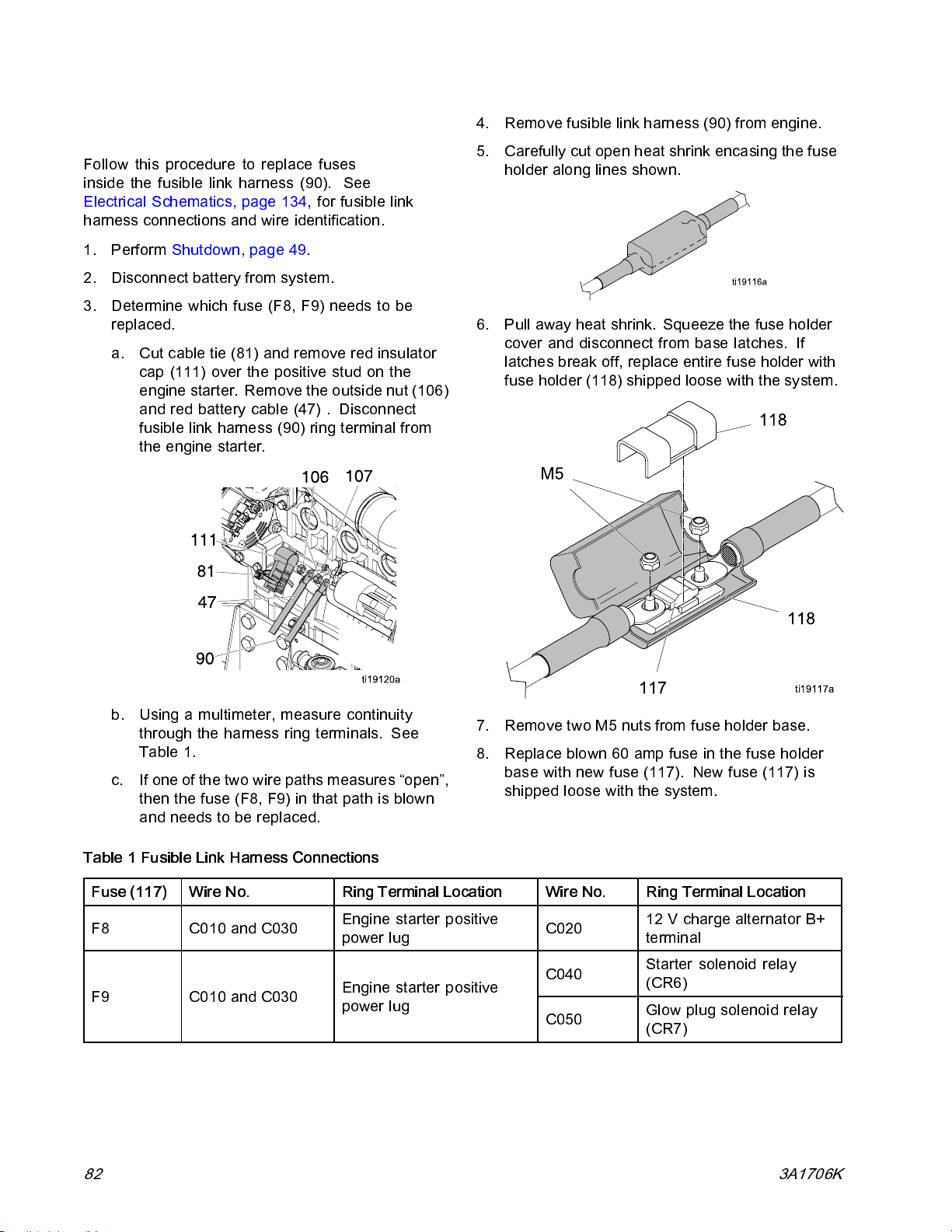
Repair
Repair Fusible Link Harness
Follow this procedure to replace fuses
inside the fusible link harness (90). See
Electrical Schematics, page 134, for fusible link
harness connections and wire identification.
1. Perform Shutdown, page 49.
2. Disconnect battery from system.
3. Determine which fuse (F8, F9) needs to be
replaced.
a. Cut cable tie (81) and remove red insulator
cap (111) over the positive stud on the
engine starter. Remove the outsi de nut (106)
and red battery cable (47) . Disconnect
fusible link harness (90) ring terminal from
the engine starter.
4. Remove fusible link harness (90) from engine.
5. Carefully cut open heat shrink encasing the fuse
holder along lines shown.
6. Pull away heat shrink. Squeeze the fuse holder
cover and disconnect from base latches. If
latches break off, replace entire fuse holder with
fuse holder (118) sh ipp ed loose wi th t he s y st em.
b. Using a multimeter, measure continuity
through the harness ring terminals. See
Table 1.
c. If one of the two wire paths measures “open”,
then the fuse (F8, F9) in that path is blown
and needs to be replaced.
Table 1 Fusible Link Harness Connections
Fuse (117) Wire No. Ring Terminal Location Wire No. Ring Terminal Location
F8
F9
C010 and C030
C010 and C030
Engine starter positive
power lug
Engine starter positive
power lug
7. Remove two M5 nuts from fuse holder base.
8. Replaceblown60ampfuseinthefuseholder
base with new fuse (117). New fuse (117) is
shipped l oos e with the sys tem.
C020
C040
C050
12 V charge alternator B+
terminal
Starter solenoid relay
(CR6)
Glow plug solenoid relay
(CR7)
82 3A1706K
Page 83

Repair
9. Replace M5 nuts over fuse and ring terminals.
Torque to 44 in.-lbs (5 N●m).
10. Connect fuse holder cover to fuse holder base.
Wrap entire fuse holder and heat shrink 3–4
times with tape (44).
NOTICE
Ensure tape entirely covers heat shrink.
Failure to seal the cut heat shrink with tape
may allow fluid to contact fusible link and
damage the fusible link.
11. Connect fusible link harness (90) and battery
cable to engine starter with nuts (106). Secure
to solenoid relay bracket with cable ties (81),
shipped l oos e with system.
12. Snap the cap insulator (111) over the red battery
cable (47). Position the red cap insulator so that
the stud is not exposed.
13. Insert cable tie (81) through cap insulator (111)
and tighten to the red battery cable (47). Ensure
that the stud is not exposed.
14. Reconnect black battery cable to the negative (-)
battery terminal and the red battery cable to the
positive (+) battery terminal.
NOTICE
Always connect the red battery cable to battery
positive (+) terminal and the black battery cable
to the battery negative (-) terminal. Failure
to properly connect the battery cable to the
battery will damage the fusible link harness.
Do not bypass the fusible link when damaged.
The fusible link prevents damage to other
system components.
3A1706K 83
Page 84
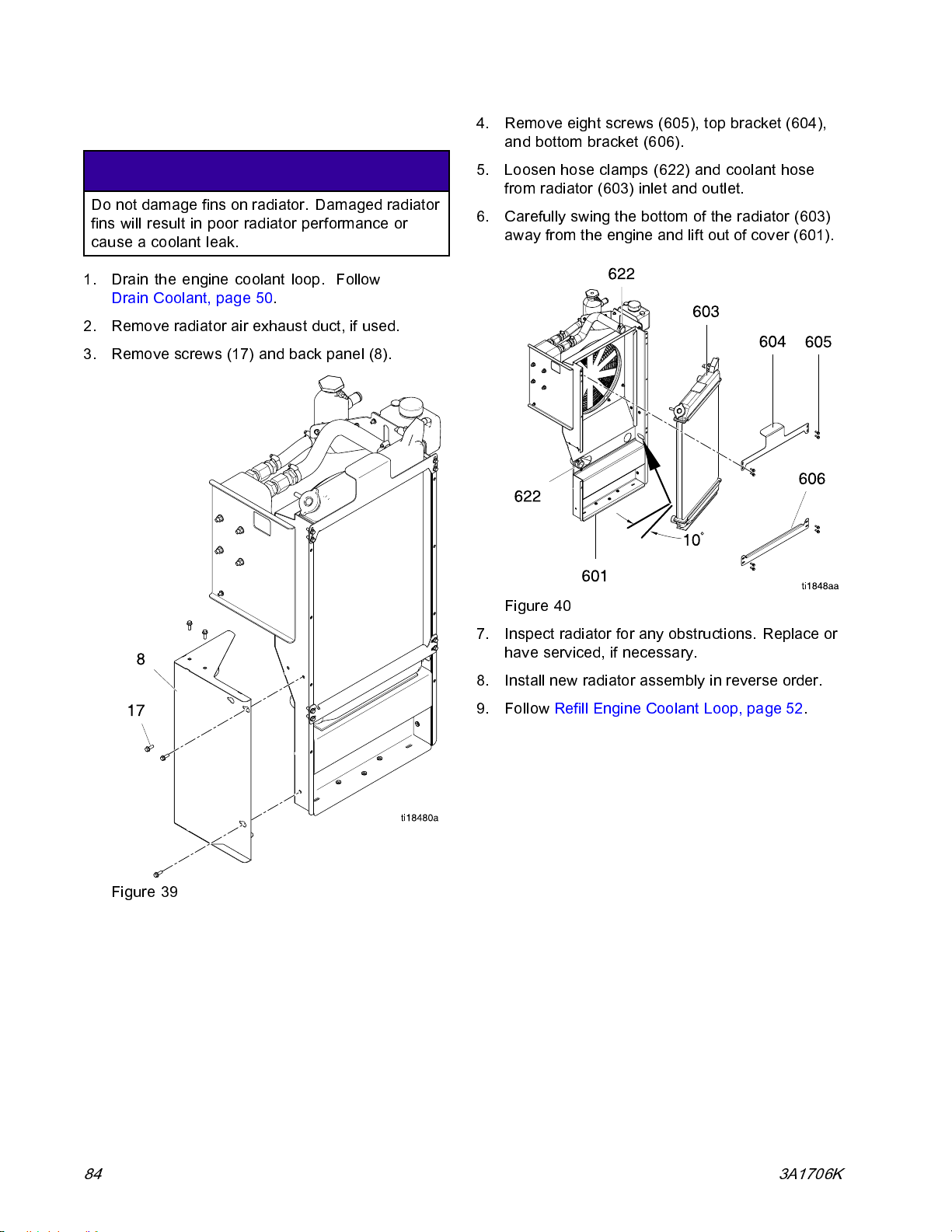
Repair
Remove Radiator
NOTICE
Do not damage fins on radiator. Damaged rad iator
fins will result in poor radiator performance or
cause a coolant leak.
1. Drain the engine coolant loop. Follow
Drain Coolant, page 50.
2. Remove radiator air exhaust duc t, if used.
3. Remove screws (17) an d back panel (8).
4. Remove eight screws (605), top bracket (60 4),
and bottom bracket (606).
5. Loosen hose clamps (622) and coolant hose
from radiator (603) inlet and outlet.
6. Carefully swing the bottom of the radiator (603)
away from the engine and lift out of cover (601).
Figure 39
Figure 40
7. Inspect radiator for any obstructions. Replace or
have serviced, if necessary.
8. Install new radiator assembly in reverse order.
9. Follow Refill Engine Coolant Loop, page 52.
84 3A1706K
Page 85
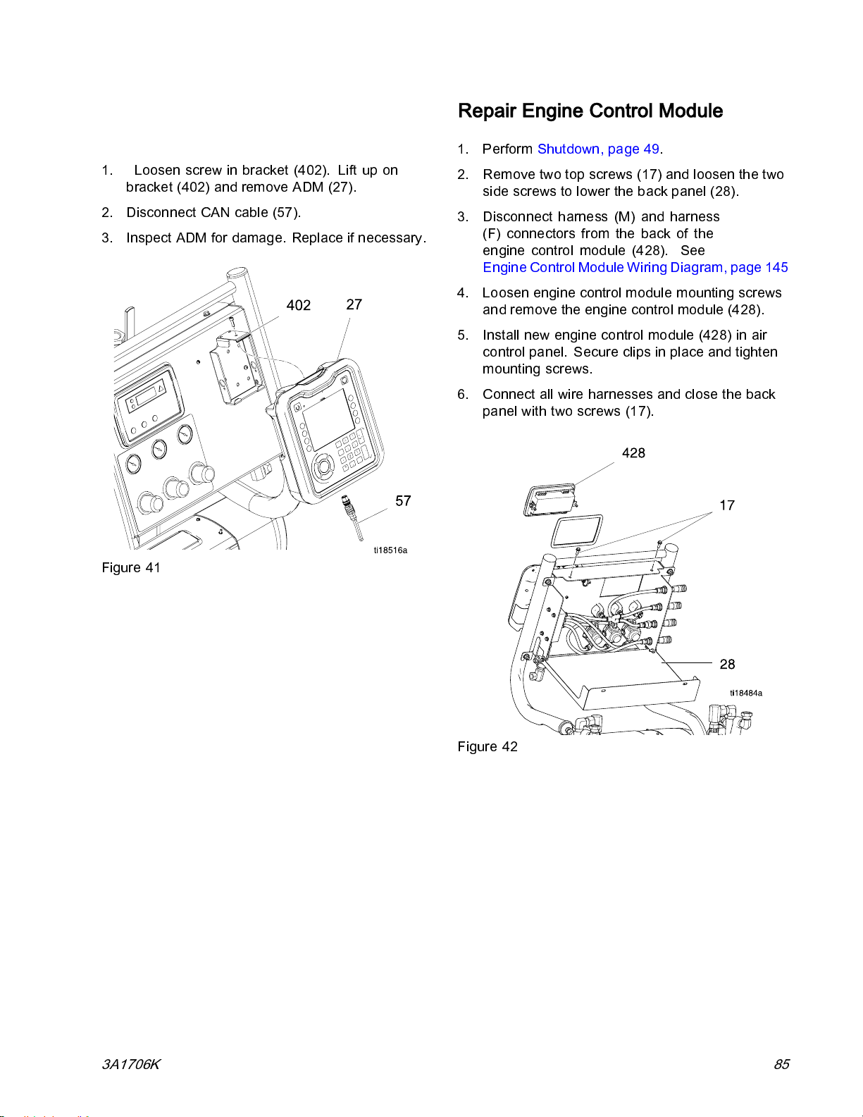
Repair
Repair Advanced Display Module (ADM)
1. Loosen screw in bracket (402). Lift up on
bracket (402) and remove ADM (27).
2. Disconnect CAN cable (57).
3. Ins pe ct ADM for da mag e. Repl ac e i f nec es sary .
Repair Engine Control Module
1. Perform Shutdown, page 49.
2. Remove two top screws (17) and loosen the two
side screws to lower the back panel (28).
3. Disconnect harness (M) and harness
(F) connectors from the back of the
engine control module (428). See
Engine Control Module Wiring Diagram, page 145
4. Loosen engine control module mounting screws
and remove the engine control mod ule (428).
5. Install new engine control module (428) in air
control panel. Secure clips in place and tighten
mounting screws.
6. Connect all wire harnesses and close the back
panel with two screws (17).
Figure 41
Figure 42
3A1706K 85
Page 86
Repair
Replace Motor Control Module (MCM)
See Fig. 43, page 86.
1. Perform Shutdown, page 49.
2. Remove four screws (73, 74) and two guards
(68).
3. Disconnect connectors from MCM (205).
Disconnect two power cables. See
Electrical Schematics, page 134.
4. Loosen top two bolts (258) and rem ove five lower
screws (258) and washers (256, 257) . Two
mounting locations use lock tooth wa sher (282).
5. Lift the MCM (205) out of bracket.
6. Install two sc rews (258) and washers (256, 257)
in top of new MCM (205).
7. Slide MCM (205) in bracket and allow the MCM
to rest on the top two s crews (258).
8. Install mounting screws (258) and washers (256,
257). Only two mounting locations use lock tooth
washer (282).
9. Ensure rotary switch is set to proper position for
E-30i or E-XP2i system. 0= E–30i and 1= E -XP2i .
10. Connect connectors to MCM. See
Electrical Schematics, page 134.
Replace High Power Temperature Control Module (HPTCM)
See Fig. 45, page 86.
2. Remove hole plug, screw (551), and washer
(554) from the back side of the electrical
enclosure.
3. Open electrical enclosure door (502).
4. Disconnect all connectors from the HPTCM (542)
inside and outside the power distribution box.
5. Remove screw (551) and washer (554) from
mounting bracket (536).
6. Install new HPTCM module (542). Reassemble
parts in reverse order.
Replace Low Power Temperature Control Module (LPTCM)
See Fig. 44, page 86.
1. Perform Shutdown, page 49.
2. Open electrical enclosure door (502).
3. Disconnect all connectors from the LPTCM (543)
inside and outside the power distribution box.
4. Loosen mounting bolts on LPTCM (543) and
disconnect module from base (544).
Note
Loosen nuts (528) to slide the back
electrical panel to the left to remove
module or base mounting bolts.
5. If the base needs to be replaced, disconnect
CAN cables, remove four mounting screws (458),
and remove ground screw in base (544).
1. Perform Shutdown, page 49.
86 3A1706K
6. Reassemble parts in reverse order.
Page 87
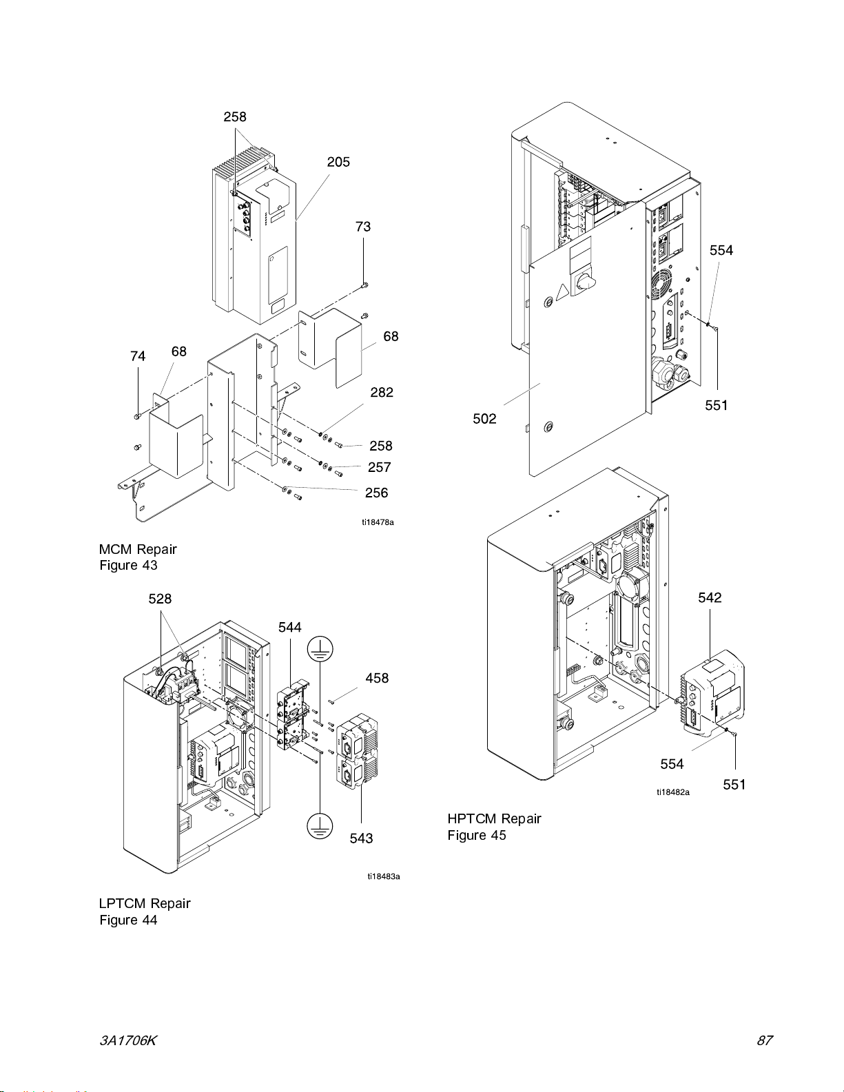
Repair
MCM Repair
Figure 43
LPTCM Repair
Figure 44
HPTCM Repair
Figure 45
3A1706K 87
Page 88
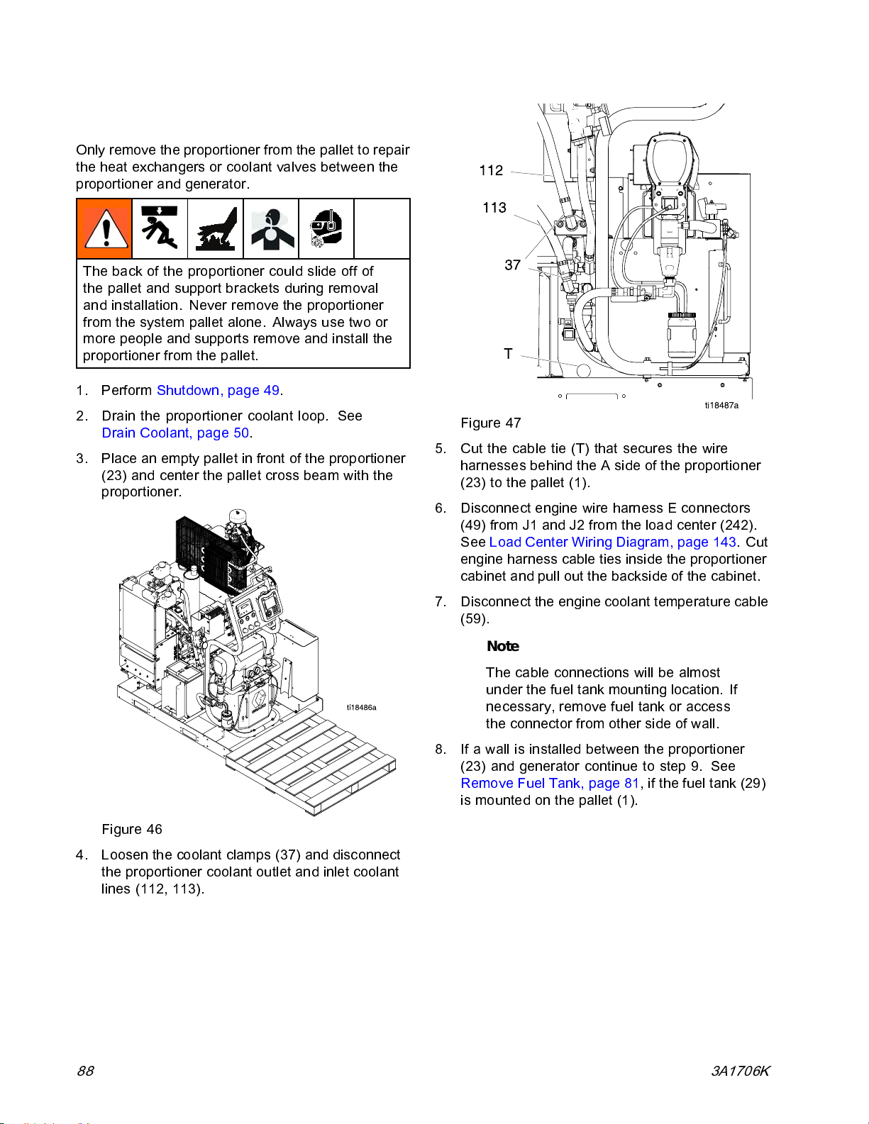
Repair
Remove Proportioner
Only remove the proportioner from the pallet to repair
the heat exchangers or cool ant valves between the
proportioner and generator.
The back of the proportioner could slide off of
the pallet and support brackets during removal
and installation. Never remove the proportioner
from the system pallet alone. Always use two or
more people and supports remove and install the
proportioner from the pallet.
1. Perform Shutdown, page 49.
2. Drain the proportioner coolant loop. See
Drain Coolant, page 50.
3. Place an empty pallet in front of the proportioner
(23) and center the pallet cross beam with the
proportioner.
Figure 47
5. Cut the cable tie (T) that secures the wire
harnesses behind the A side of the proportioner
(23) to the pallet (1).
6. Disconnect engine wire harness E connectors
(49) from J1 and J2 from the load center (242).
See Load Center Wiring Diagram , page 143.Cut
engine harness cable ties inside the proportioner
cabinet and pull out the backside of the cabinet.
7. Disconnect the engine coolant temperature cable
(59).
Note
The cable connections will be almost
under the fuel tank mounting location. If
necessary, remove fuel tank or access
the connector from other side of wall.
8. If a wall is installed between the proportioner
(23) and generator continue to step 9. See
Remove Fuel Tank, page 81,ifthefueltank(29)
ismountedonthepallet(1).
Figure 46
4. Loosen the coolant clamps (37) and disconnect
the proportioner coolant outlet and inlet coolant
lines (112, 113).
88 3A1706K
Page 89
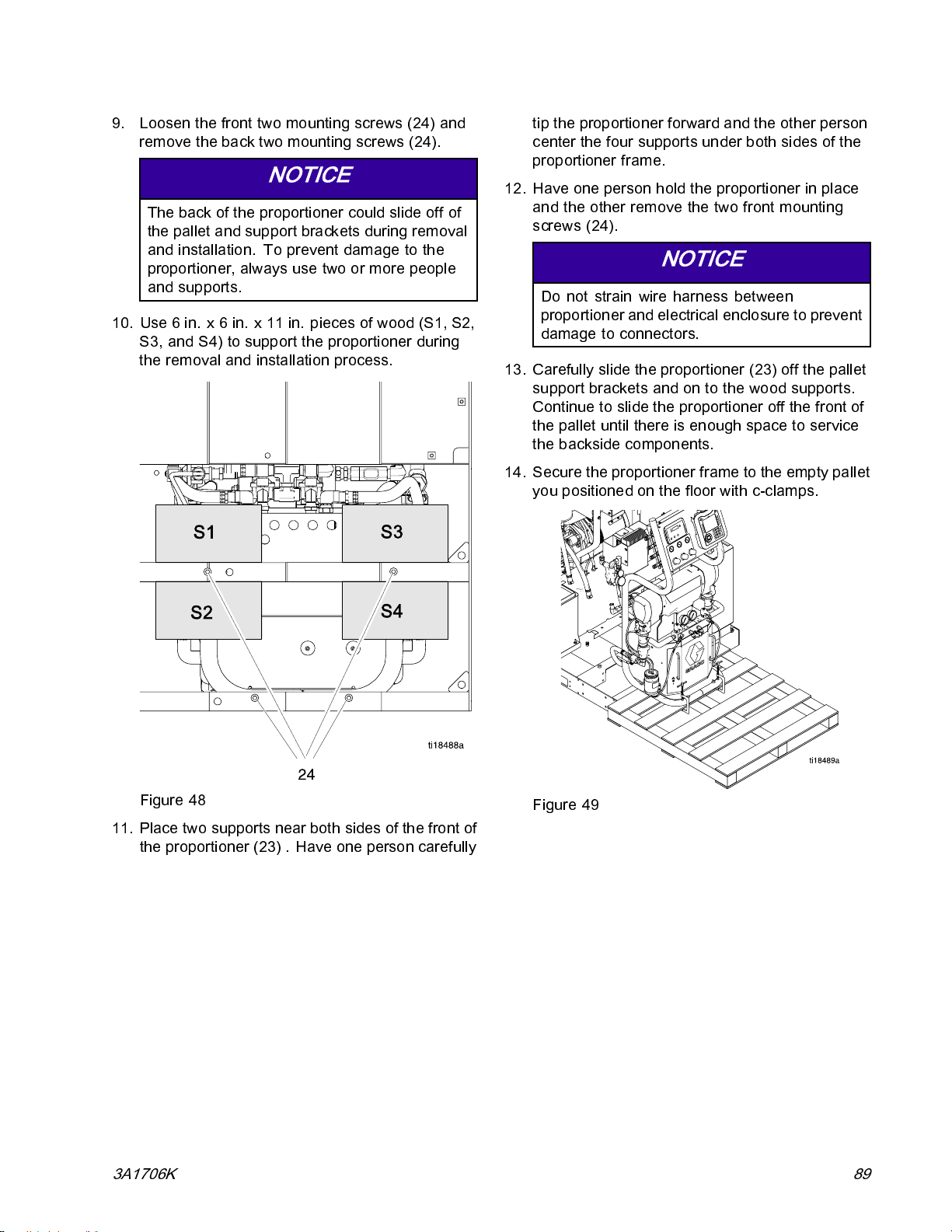
Repair
9. Loosen the front two mounting screws (24) and
remove the back two mounting screws (24).
NOTICE
The back of the proportioner could slide off of
the pallet and support brackets durin g removal
and installation. To prevent damage to the
proportioner, alw ay s use two or m ore people
and supports.
10. Use 6 in. x 6 in. x 11 in. pieces of wood (S1, S2,
S3, and S4) to support the proportioner during
the removal and installation process.
tip the proportioner forward and the other person
center the four supports under both sides of the
proportioner frame.
12. Have one person hold the proportioner in place
and the other remove the two front mounting
screws (24).
NOTICE
Do not strain wire harness between
proportioner a nd electrical enclosure to prevent
damage to connectors.
13. Carefully slide the proportioner (23) off the pallet
support brackets and on to the wood supports.
Continue to slide the proportioner off the front of
thepalletuntilthereisenoughspacetoservice
the backside components.
14. Secure the proportioner frame to the empty pallet
you positioned on the floor with c-clamps.
Figure 48
11. Place two supports near both sides of the front of
the proportioner (23) . Have one person carefully
3A1706K 89
Figure 49
Page 90
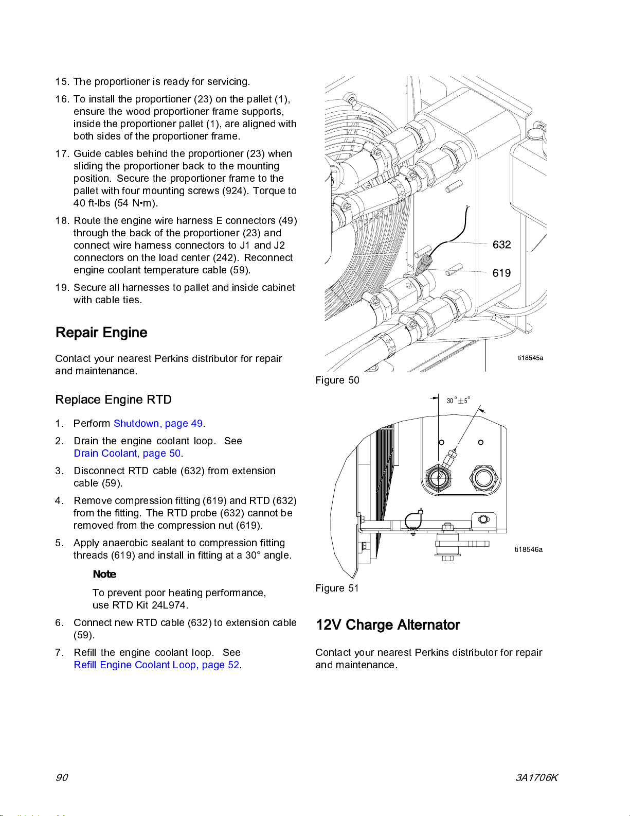
Repair
15. The proportioner is ready for servicing.
16. To install the proportioner (23) on the pallet (1),
ensure the wood proportioner frame supports,
inside the proportioner pallet (1), are aligned with
both sides of the proportioner frame.
17. Guide cables behind th e proportioner (23) when
sliding the proportioner back to the mounting
position. Secure the proportioner frame to the
pallet with four mounting screws (924). Torque to
40 ft-lbs (54 N•m).
18. Route the engine wire harness E connectors (49)
through the back of the proportioner (23) and
connect wire harness connectors to J1 and J2
connectors on the load center (242). Reconnect
engine coolant temperature cable (59).
19. Secure all harnesses to pallet and inside cabinet
with cable ties.
Repair Engine
Contact your nearest Perkins distributor for repair
and maintenance.
Replace Engine RTD
1. Perform Shutdown, page 49.
2. Drain the engine coolant loop. See
Drain Coolant, page 50.
3. Disconnect RTD cable (632) from extension
cable (59).
4. Remove compression fitting (619) and RTD (63 2)
from the fitting. The RTD probe (632) cannot be
removed from the compression nut (619).
5. Apply anaerobic sealant to compression fitting
threads (619) and install in fitting at a 30° angle.
Note
To prevent poor heating performance,
use RTD Kit 24L974.
6. Connect new RTD cable (632) to extension cable
(59).
7. Refill the engine coolant loop. See
Refill Engine Coolant Loop, page 52.
Figure 50
Figure 51
12V Charge Alternator
Contact your nearest Perkins distributor for repair
and maintenance.
90 3A1706K
Page 91
Notes
Notes
3A1706K 91
Page 92
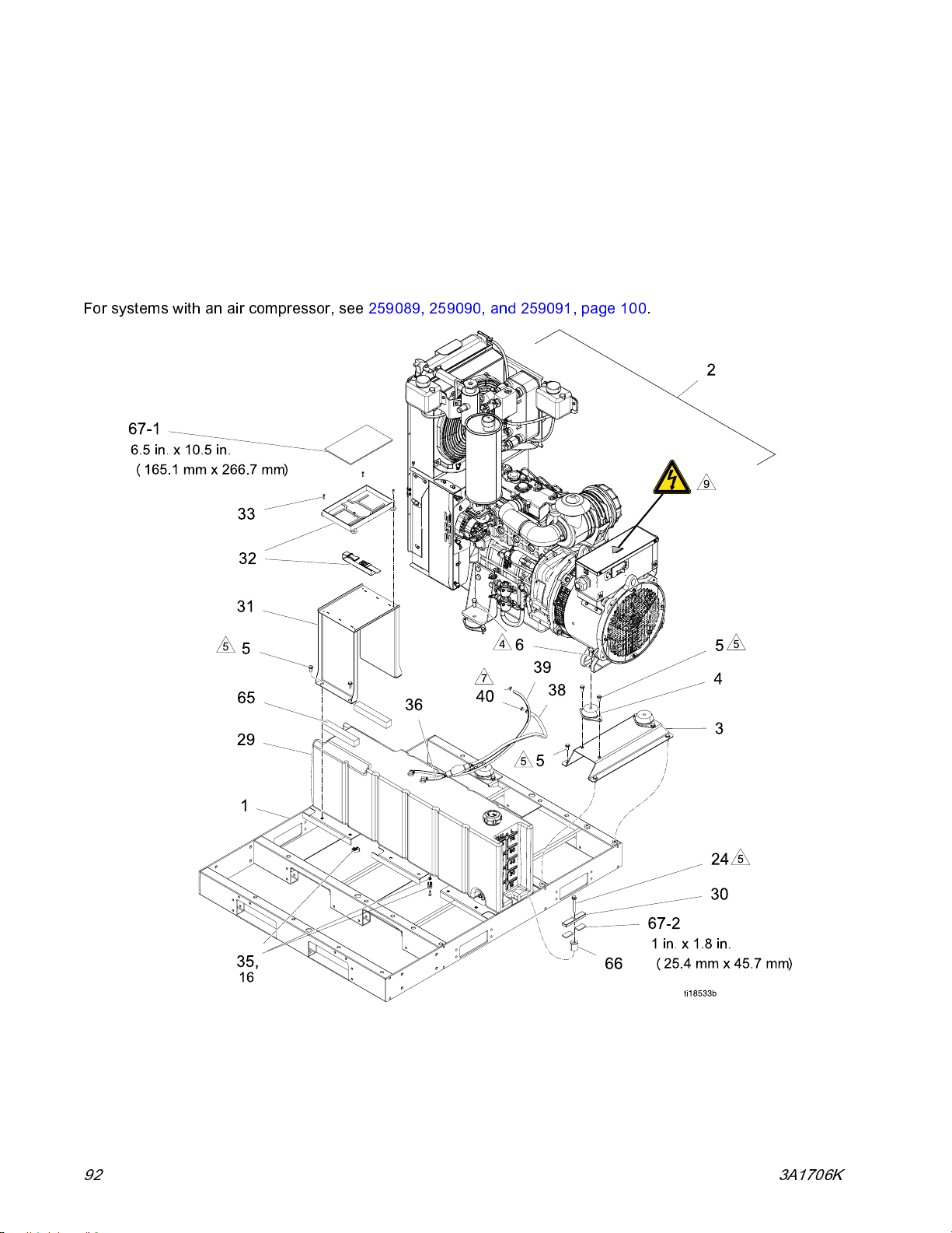
Parts
Parts
Systems
259079, E-30i
259080. E-30i with Booster Heat
259081, E-XP2i with Booster Heat
For systems with an air compressor, see 259089, 259090, and 259091, page 10 0.
92 3A1706K
Page 93
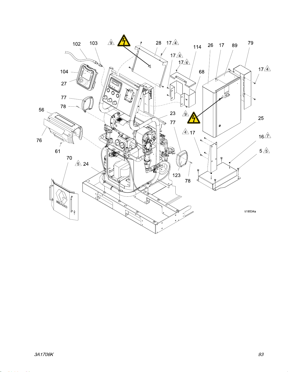
Parts
3A1706K 93
Page 94

Parts
94 3A1706K
Page 95
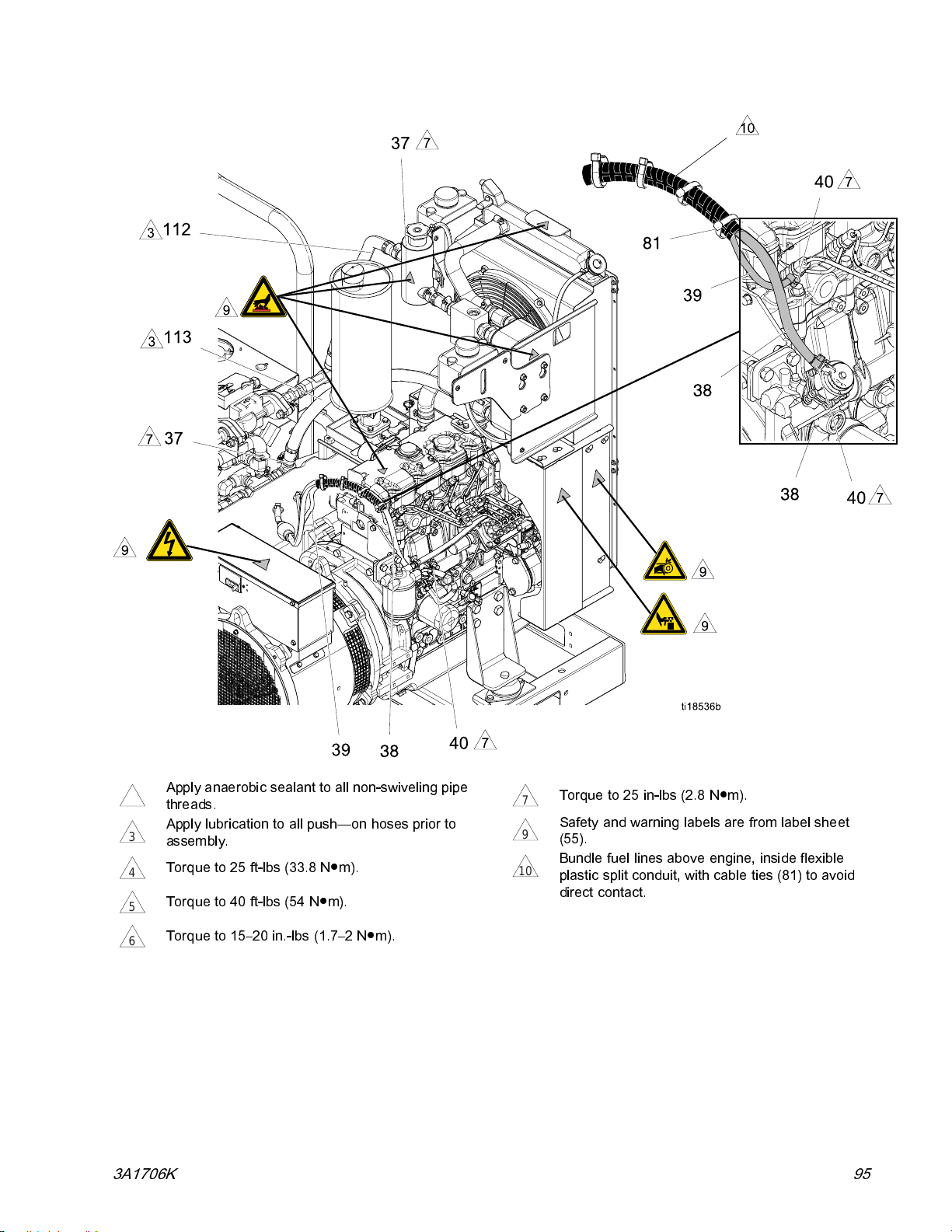
Parts
Apply anaerobic sealant to all non-swiveling pipe
2
threads.
Apply lubrication to all push—on hoses prior to
3
assembly.
Torque to 25 ft-lbs (33.8 N●m).
4
Torque to 40 ft-lbs (54 N●m).
5
Torque to 15–20 in.-lbs (1.7–2 N●m).
6
Torque to 25 in-lbs (2.8 N●m).
7
Safety and warning labels are from label sheet
9
(55).
Bundle fuel lines above engine, inside flexible
10
plastic split conduit, with cable ties (81) to avoid
direct contact.
3A1706K 95
Page 96

Parts
Quantity
Ref Part Description 259079 259080 259081
1 24J658
2
316H732
4 24L953 KIT, isolator (4 pack) 1 1 1
5
6 105324
816H898
916H894
16 115942
17 113161 SCREW, flanged, hex hd; 0.5 in. (13 mm), 1/4–20 36 36 36
21 125625
23
—
111192
—
—
—
BASE, pallet 1 1 1
GENERATOR, diesel, 22kw, see
22kW Diesel Generator, page 124 111
SUPPORT, generator 1 1 1
SCREW, cap flange hd; 0.875 in. (22 mm), 3/8–16 22 22 22
SCREW, cap, hex hd; 1.2 in (30 mm), M12 x 1.75 4 4 4
GUARD, engine, right 1 1 1
GUARD, engine, left 1 1 1
NUT, hex, flange head; 1/4–20 4 4 4
TIE, cable, fir tree 5 5 5
PROPORTIONER, E–30i, (230v, 1ph), see
Proportioners, page 104 1
PROPORTIONER, E–30i, (4.0kw, 230v, 1ph), see
Proportioners, page 104 1
PROPORTIONER, E-xp2i, (4.0kw, 230v, 1ph), see
Proportioners, page 104 1
24 125626
25 16H456 BRACKET, mounting 1 1 1
26
27 24L948
28 16H880
29 24K390
30 16J889 BRACKET, support, fuel tank 2 2 2
—
—
SCREW, hex hd, flanged; 3 in. (76 mm), 3/8–16 6 6 6
ENCLOSURE, electrical, heat, se e
Electrical Enclosure, page 121 11
ENCLOSURE, electrical, non-heat, see
Electrical Enclosure, page 121 1
MODULE, ADM 1 1 1
COVER, air panel 1 1 1
TANK, fuel, see Fuel Tank, page 131 111
96 3A1706K
Page 97
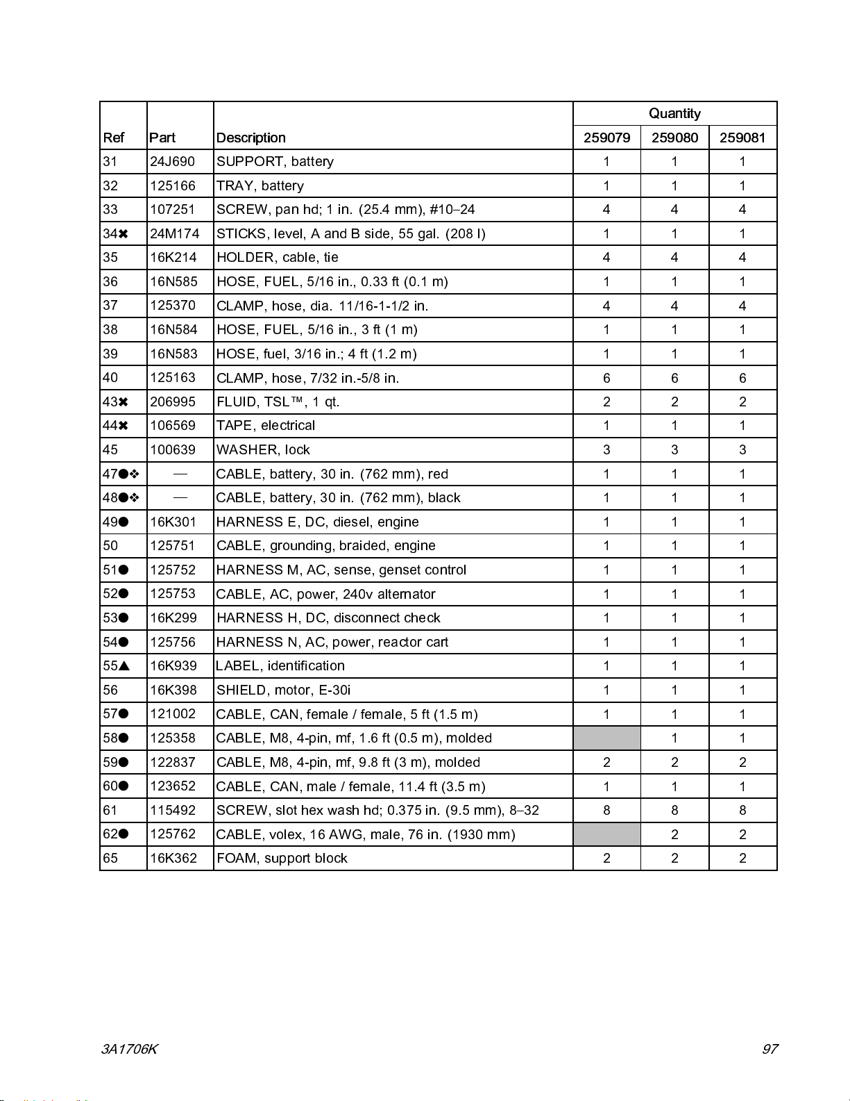
Parts
Quantity
Ref Part Description 259079 259080 259081
31 24J690
32 125166 TRAY, battery 1 1 1
33 107251 SCREW, pan hd; 1 in. (25.4 mm), #10–24 4 4 4
34✖ 24M174
35 16K214
36 16N585
37 125370
38 16N584
39 16N583 HOSE, fuel, 3/16 in.; 4 ft (1.2 m) 1 1 1
40 125163
43✖ 206995
44✖ 106569 TAPE, electrical 1 1 1
45 100639
47
48
49
50 125751
—
—
16K301
SUPPORT, battery 1 1 1
STICKS, level, A and B side, 55 gal. (208 l) 1 1 1
HOLDER, cable, tie 4 4 4
HOSE, FUEL, 5/16 in., 0. 33 ft (0.1 m) 1 1 1
CLAMP, hose, dia. 11/16-1-1/2 in. 4 4 4
HOSE, FUEL, 5/16 in., 3 ft (1 m) 1 1 1
CLAMP, hose, 7/32 in.-5/8 in. 6 6 6
FLUID, TSL™, 1 qt. 2 2 2
WASHER, lock 3 3 3
CABLE, batte ry, 30 in. (762 mm), red 1 1 1
CABLE, battery, 30 in. (762 mm), black 1 1 1
HARNESS E, DC, diesel, en gine 1 1 1
CABLE, grounding, braided, engine 1 1 1
51
125752
52
125753
53
16K299 HARNESS H, DC, disconnect check 1 1 1
54
125756
55
▲
16K939
56 16K398
57
121002
58
125358
59
122837 CABLE, M8, 4-pin, mf, 9.8 ft (3 m), molded 2 2 2
60
123652
61 115492
62
125762
65 16K362
HARNESS M, AC, sense, ge nset control 1 1 1
CABLE, AC, power, 240v alternator 1 1 1
HARNESS N, AC, power, reactor cart 1 1 1
LABEL, identification 1 1 1
SHIELD, motor, E-30i 1 1 1
CABLE, CAN, female / female, 5 ft (1.5 m) 1 1 1
CABLE, M8, 4-pin, mf, 1.6 ft (0.5 m), molded 1 1
CABLE, CAN, male / female, 11.4 ft (3.5 m) 1 1 1
SCREW, slot hex wash hd; 0.375 in. (9.5 mm), 8–32 8 8 8
CABLE, volex, 16 AWG, male, 76 in. (1930 mm) 2 2
FOAM, support block 2 2 2
3A1706K 97
Page 98
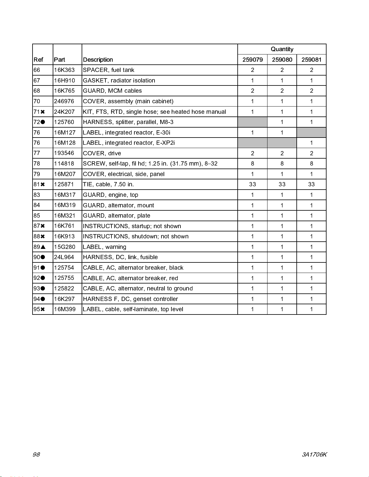
Parts
Quantity
Ref Part Description 259079 259080 259081
66 16K363
67 16H910
68 16K765
70 246976 COVER, assembly (main cabinet) 1 1 1
71✖ 24K207
72
125760
76 16M127 LABEL, integrated reactor, E-30i 1 1
76 16M128 LABEL, inte grated reactor, E-XP2i 1
77
78 114818
79 16M207
81✖ 125871 TIE, cable, 7.50 in. 33 33 33
83 16M317 GUARD, en gine, top 1 1 1
84 16M319
85 16M321
87✖ 16K761
88✖ 16K913
193546
SPACER, fuel tank 2 2 2
GASKET, radiator isolation 1 1 1
GUARD, MCM cables 2 2 2
KIT, FTS, RTD, single hose; see heated hose manual 1 1 1
HARNESS, splitter, parallel, M8-3 1 1
COVER, drive 2 2 2
SCREW, self-tap, fil hd; 1.25 in. (31.75 mm), 8–32 8 8 8
COVER, electrical, side, panel 1 1 1
GUARD, alternator, mount 1 1 1
GUARD, alternator, plate 1 1 1
INSTRUCTIONS, startup; not shown 1 1 1
INSTRUCTIONS, shutdown; not shown 1 1 1
89
▲
15G280 LABEL, warning 1 1 1
90
24L964 HARNESS, DC, link, fusible 1 1 1
91
125754
92
125755
93
125822
94
16K297
95✖ 16M399
CABLE, AC, alternator breaker, black 1 1 1
CABLE, AC, alternator breaker, red 1 1 1
CABLE, AC, alternator, neutral to ground 1 1 1
HARNESS F, DC, genset controller 1 1 1
LABEL, cable, self-laminate, top level 1 1 1
98 3A1706K
Page 99
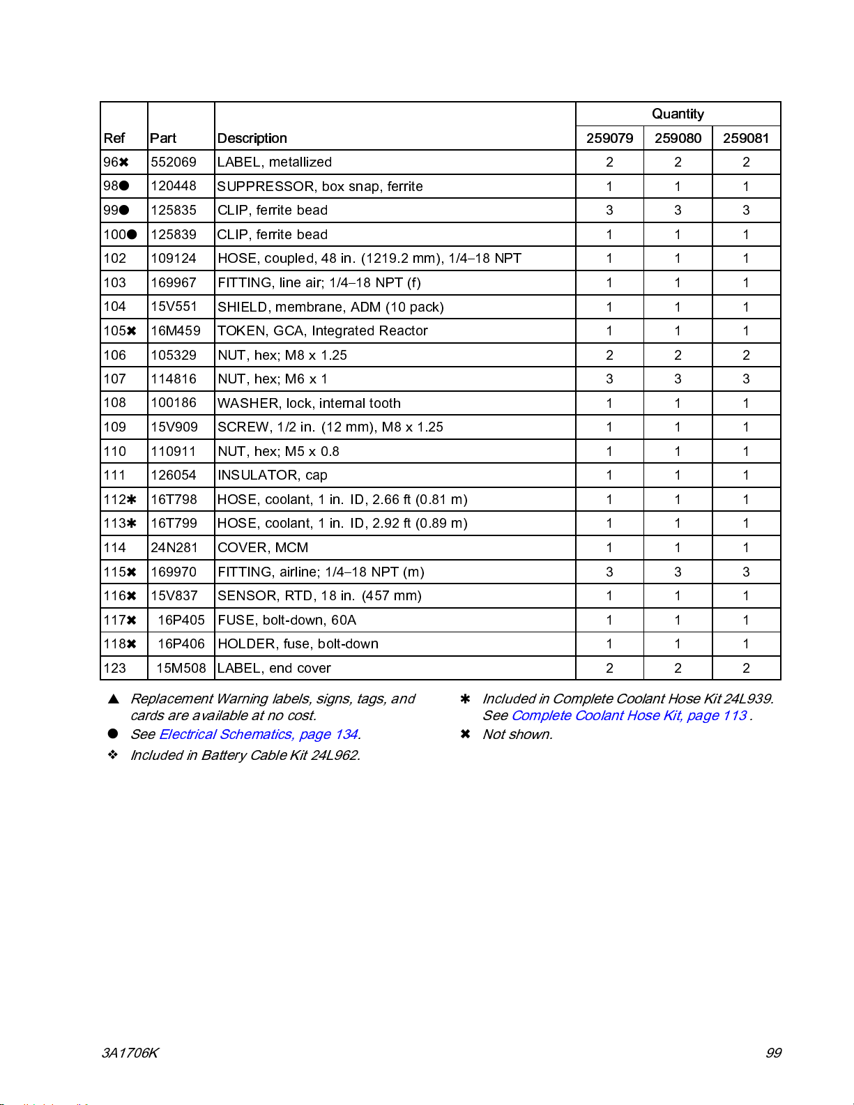
Parts
Quantity
Ref Part Description 259079 259080 259081
96✖ 552069 LABEL, metallized 2 2 2
98
99
120448
125835 CLIP, ferrite bead 3 3 3
SUPPRESSOR, box snap, ferrite 1 1 1
100125839
102 109124
103 169967
104 15V551
105✖ 16M459
106 105329 NUT, hex; M8 x 1.25 2 2 2
107 114816 NUT, hex; M6 x 1 3 3 3
108 100186
109 15V909
110 110911 NUT, hex; M5 x 0 .8 1 1 1
111 126054
11216T798
11316T799
114 24N281
115✖ 169970 FITTING, airline; 1/4–18 NPT (m) 3 3 3
116✖ 15V837
117✖ 16P405
CLIP, ferrite bead 1 1 1
HOSE, coupled, 48 in. (121 9.2 mm), 1/4–18 NPT 1 1 1
FITTING, line air; 1/4–18 NPT (f) 1 1 1
SHIELD, membrane, ADM (10 pack) 1 1 1
TOKEN, GCA, Integrated Reactor 1 1 1
WASHER, lock, internal tooth 1 1 1
SCREW,1/2in.(12mm),M8x1.25 1 1 1
INSULATOR, cap 1 1 1
HOSE, coolant, 1 in. ID, 2.66 ft (0.81 m) 1 1 1
HOSE, coolant, 1 in. ID, 2.92 ft (0.89 m) 1 1 1
COVER, MCM 1 1 1
SENSOR,RTD,18in. (457mm) 1 1 1
FUSE, bolt-down, 60A 1 1 1
118✖ 16P406
123 15M508 LABEL, end cover 2 2 2
▲
Replacement Warning labels, signs, tags, and
cards are available at no cost.
See Electrical Schematics, page 134.
Included in Battery Cable Kit 24L962.
HOLDER, fuse, bolt-down 1 1 1
Included in Complete Coolant Hose Kit 2 4L939.
See Complete Coolant Hose Kit, page 113 .
✖
Not shown.
3A1706K 99
Page 100
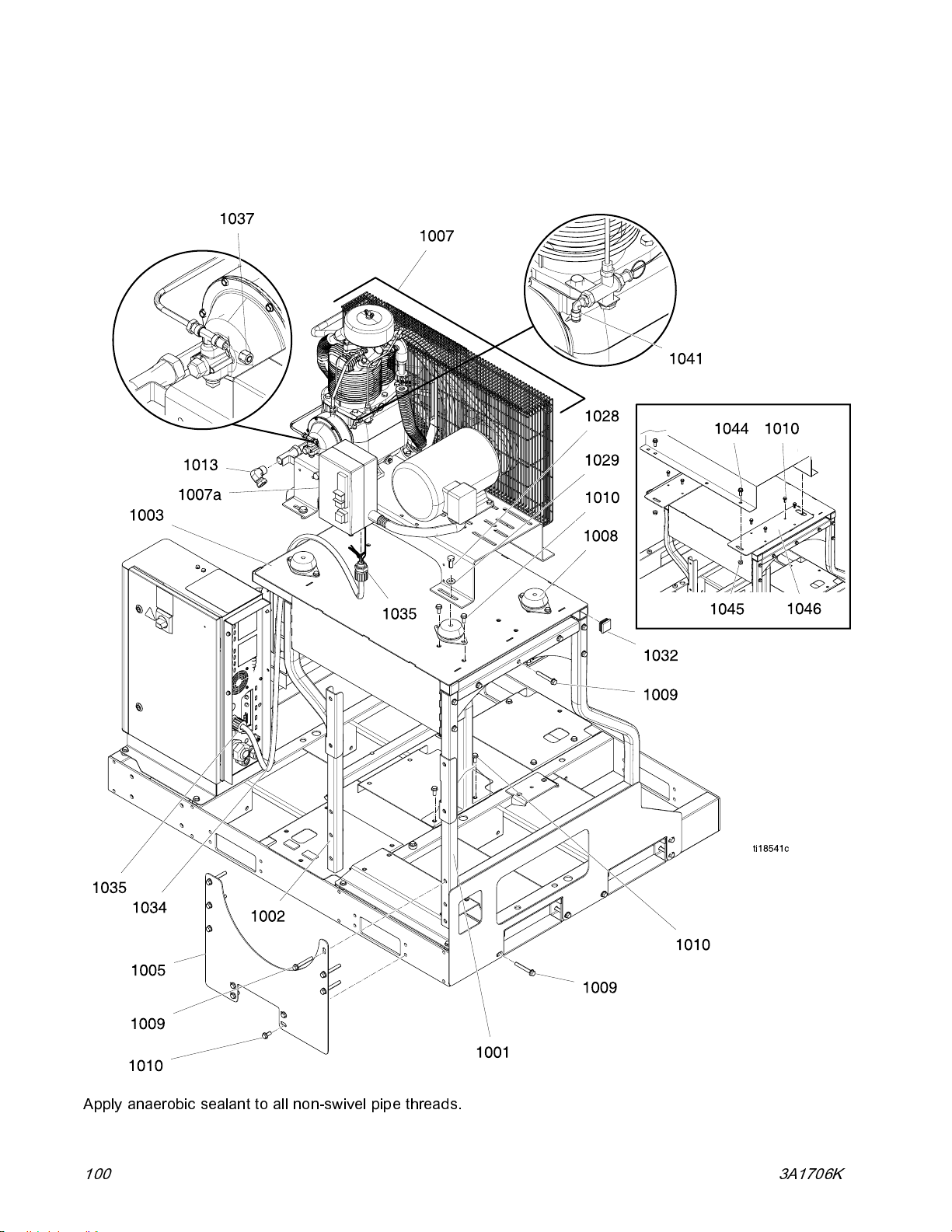
Parts
259089, E-30i with Air Compressor
259090. E-30i with Booster Heat and Air Compressor
259091, E-XP2i with Booster Heat and Air Compressor
Apply anaerobic sealant to all non-swivel pipe threads.
100 3A1706K
 Loading...