

Page 1
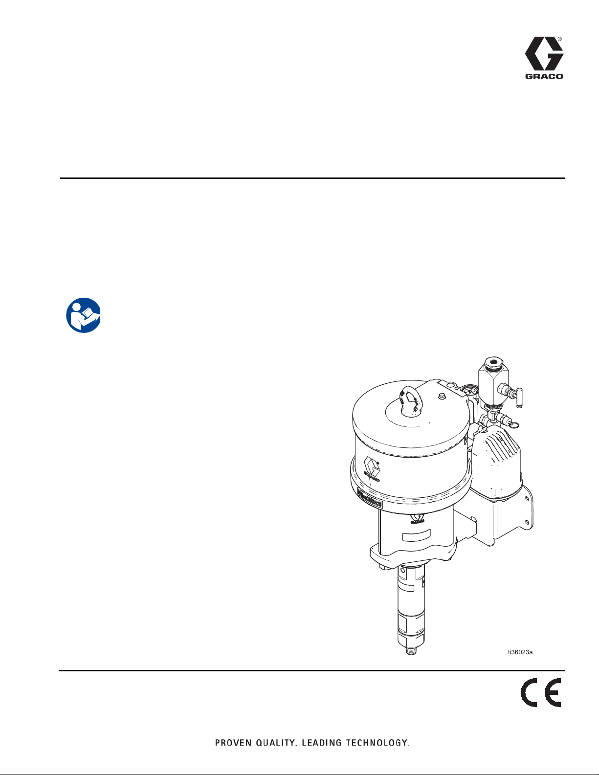
Instructions-Parts
®
Python
XL-DA25
3A6831A
Pump
Pneumatic pump for injecting chemicals at well sites. Not for use with sour gas.
For professional use only.
Not approved for use in European explosive atmosphere locations.
See page 3 for model information, including maximum working pressures.
Important Safety Instructions
Read all warnings and instructions in this manual.
Save all instructions.
EN
Page 2

Contents
Models . . . . . . . . . . . . . . . . . . . . . . . . . . . . . . . . . . . 3
Pump Models . . . . . . . . . . . . . . . . . . . . . . . . . . . 3
Configuration Number Matrix . . . . . . . . . . . . . . . . . 4
Pump Configuration . . . . . . . . . . . . . . . . . . . . . . 4
Lower Configuration . . . . . . . . . . . . . . . . . . . . . . 4
Warnings . . . . . . . . . . . . . . . . . . . . . . . . . .5
Installation . . . . . . . . . . . . . . . . . . . . . . . . . . . . . . . . 7
Grounding . . . . . . . . . . . . . . . . . . . . . . . . . . . . . . 7
Required Accessories . . . . . . . . . . . . . . . . . . . . . 7
Flush Before Using Equipment . . . . . . . . . . . . . . 7
Typical Installation . . . . . . . . . . . . . . . . . . . . . . . 8
Mount the Pump and Connect Chemical Supply 8
Connect Pneumatic Supply . . . . . . . . . . . . . . . . . 9
Route Exhaust to Remote Location . . . . . . . . . . 9
Connect Chemical Outlet . . . . . . . . . . . . . . . . . . 9
Operation . . . . . . . . . . . . . . . . . . . . . . . . . . . . . . . . 11
Pressure Relief Procedure . . . . . . . . . . . . . . . . 11
Flush the Equipment . . . . . . . . . . . . . . . . . . . . . 11
Prime the Pump . . . . . . . . . . . . . . . . . . . . . . . . 12
Calibrate Chemical Dosage . . . . . . . . . . . . . . . 12
Maintenance . . . . . . . . . . . . . . . . . . . . . . . . . . . . . . 13
Preventive Maintenance Schedule . . . . . . . . . . 13
Tighten Threaded Connections . . . . . . . . . . . . . 13
Tighten Packings . . . . . . . . . . . . . . . . . . . . . . . 13
Storage . . . . . . . . . . . . . . . . . . . . . . . . . . . . . . . 13
Troubleshooting . . . . . . . . . . . . . . . . . . . . . . . . . . 14
Repair - Pump Lower . . . . . . . . . . . . . . . . . . . . . . . 15
Disconnect the Pump Lower . . . . . . . . . . . . . . . 15
Pump Repair . . . . . . . . . . . . . . . . . . . . . . . . . . . 16
Reconnect the Pump Lower . . . . . . . . . . . . . . . 18
Repair - Pneumatic Motor . . . . . . . . . . . . . . . . . . . 19
Pneumatic Valve . . . . . . . . . . . . . . . . . . . . . . . . 19
Replace Pilot Valves . . . . . . . . . . . . . . . . . . . . . 22
Repair Pneumatic Motor . . . . . . . . . . . . . . . . . . 23
Parts . . . . . . . . . . . . . . . . . . . . . . . . . . . . . . . . . . . . 27
Python XL-DA25 Pneumatic Pump . . . . . . . . . . 27
Pump Lower . . . . . . . . . . . . . . . . . . . . . . . . . . . 29
Pneumatic Motor Parts . . . . . . . . . . . . . . . . . . . 31
Pneumatic Valve Parts . . . . . . . . . . . . . . . . . . . 33
Kits and Accessories . . . . . . . . . . . . . . . . . . . . . . 35
Pump Lower Models . . . . . . . . . . . . . . . . . . . . . 35
Additional Kits & Accessories . . . . . . . . . . . . . . 35
Dimensions . . . . . . . . . . . . . . . . . . . . . . . . . . . . . . . 36
Python XL-DA25 Pump Dimensions . . . . . . . . . 36
Wall Bracket Mounting Hole Diagram . . . . . . . . 37
Pneumatic Mounting Hole Diagrams . . . . . . . . . 38
Performance Charts . . . . . . . . . . . . . . . . . . . . . . . . 39
6 in. Motors . . . . . . . . . . . . . . . . . . . . . . . . . . . . 39
7.5 in. Motors . . . . . . . . . . . . . . . . . . . . . . . . . . . 40
Technical Specifications . . . . . . . . . . . . . . . . . . . . 41
Graco Standard Warranty . . . . . . . . . . . . . . . . . . . 42
2 3A6831A
Page 3
Models
Models
Pneumatic
Plunger Size
3/4 in.
1 in. 3,800 (2.6, 26)
3/4 in.
1 in. 6,100 (42.1, 421)
Motor Size
6.0 in.
7.5 in.
Maximum Working Pressure
psi (MPa, bar)
6,400 (44.1, 441)
10,000 (68.9, 689)
Maximum Pneumatic Inlet Pressure
psi (MPa, bar)
100 (0.69, 6.9)
NOTE: See the Configuration Number Matrix, page 4, to find the plunger and pneumatic motor size for your unit.
Pump Models
Part Number Configuration Code Motor Size Lower Size Lower Coating Seal Material
A22606 PCI-0600-075-113-XC-2-0
A22607 PCI-0600-075-113-XD-2-0 FFKM
A22608 PCI-0600-075-113-XE-2-0 TFE/P
A22612 PCI-0600-100-138-XC-2-0
A22613 PCI-0600-100-138-XD-2-0 FFKM
A22614 PCI-0600-100-138-XE-2-0 TFE/P
A22706 PCI-0750-075-113-XC-2-0
A22707 PCI-0750-075-113-XD-2-0 FFKM
A22708 PCI-0750-075-113-XE-2-0 TFE/P
A22712 PCI-0750-100-138-XC-2-0
A22713 PCI-0750-100-138-XD-2-0 FFKM
A22714 PCI-0750-100-138-XE-2-0 TFE/P
6.0 in.
7.5 in.
3/4 in. Chromex
1 in. Chromex
3/4 in. Chromex
1 in. Chromex
HNBR
HNBR
HNBR
HNBR
3A6831A 3
Page 4

Configuration Number Matrix
Configuration Number Matrix
Check the identification plate (ID) for the 17-digit Configuration Number of your pump. Use the following matrix to
define the components of your pump.
NOTE: Not all combinations are possible.
Sample Configuration Number: PCI-0600-075-113-XC-2-0
PCI 0600 075 113 X C 2 0
Pneumatic
Chemical
Injection
Pump Configuration
Pneumatic
Motor Size
Pump Lower
Primary Seal
Size
Pump Lower
Secondary
Seal Size
Pump Lower
Coating
Seal Material Pump Stroke
Length
Qualifier
Pneumatic
Motor Size
0600 6.0 in. 075 3/4 in. diameter 113 1-1/8 in. diameter X Chromex C HNBR 2 2.5 inch 0 None
0750 7.5 in. 100 1 in. diameter 138 1-3/8 in. diameter DFFKM
Pump Lower
Primary Seal Size
Pump Lower
Secondary Seal Size
Pump Lower
Coating
Seal
Material
ETFE/P
Pump Stroke
Length
Qualifier
4 3A6831A
Page 5
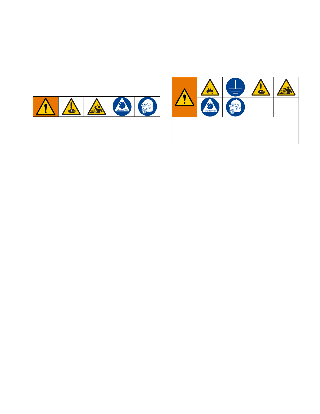
Warnings
Warnings
The following warnings are for the setup, use, grounding, maintenance, and repair of this equipment. The exclamation point symbol alerts you to a general warning and the hazard symbols refer to procedure-specific risks. When
these symbols appear in the body of this manual or o n warning labels, refer back to these Warnings. Product-specific
hazard symbols and warnings not covered in this section may appear throughout the body of this manual where
applicable.
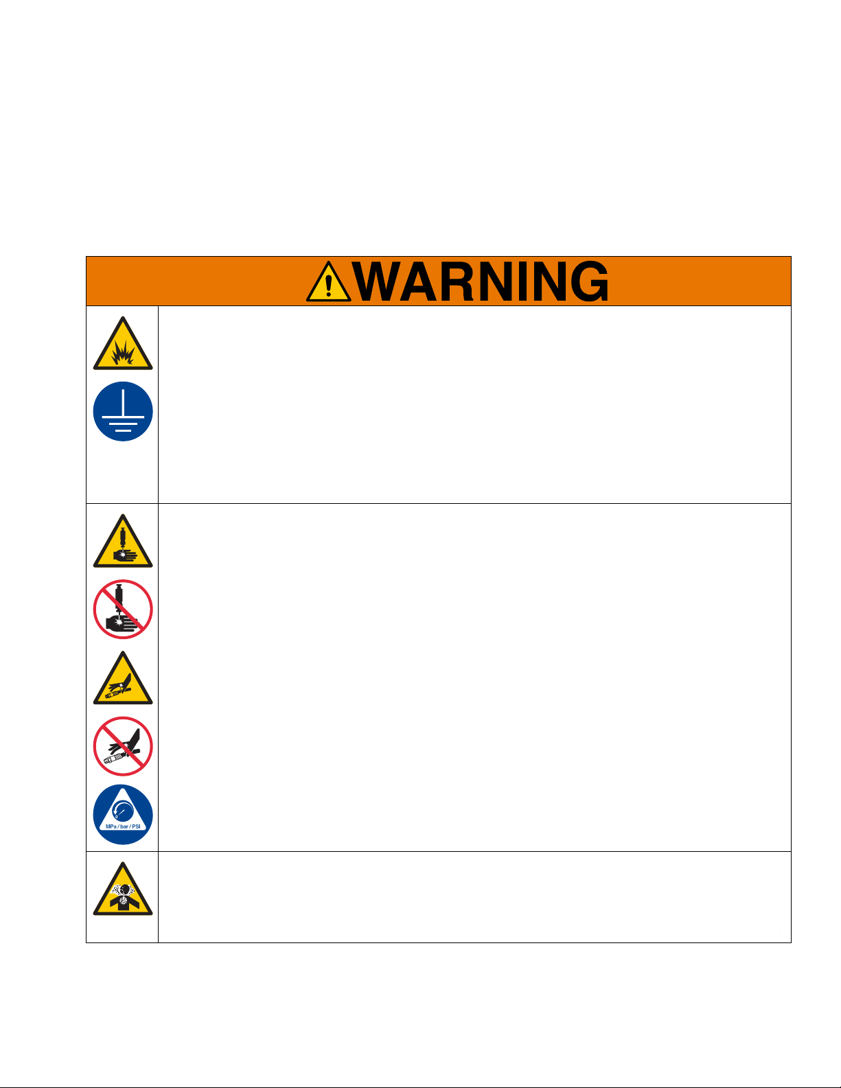
FIRE AND EXPLOSION HAZARD
When flammable fluids are present in the work area be aware that flammable fumes can ignite or
explode. To help prevent fire and explosion:
• Use equipment only in well ventilated area.
• Eliminate all ignition sources, such as cigarettes and portable electric lamps.
• Ground all equipment in the work area.
• Keep work area free of debris, including rags and spilled or open containers of solvent.
• Do not plug or unplug power cords or turn lights on or off when flammable fumes are present.
• Use only grounded hoses.
• Stop operation immediately if static sparking occurs or you feel a shock. Do not use equipment until
you identify and correct the problem.
• Keep a working fire extingui she r in the wor k ar ea .
SKIN INJECTION HAZARD
High-pressure fluid from dispensing device, hose leaks, or ruptured components will pierce skin. This
may look like just a cut, but it is a serious injury that can result in amputation. Get immediate surgical
treatment.
• Do not put your hand over the fluid outlet.
• Do not stop or deflect leaks with your hand, body, glove, or rag.
• Follow the Pressure Relief Procedure when you stop dispensing and before cleaning , checking, or
servicing equipment.
• Tighten all fluid connections before operating the equipment.
• Check hoses and couplings da ily. Re pla ce worn or dam ag e d pa rt s immed ia tely.
TOXIC FLUID OR FUMES HAZARD
Toxic fluids or fumes can cause serious injury or death if splashed in the eyes or on skin, inhaled, or
swallowed.
• Read Safety Data Sheet (SDS) to know the specific hazards of the fluids you are using.
• Store hazardous fluid in approved containers, and dispose of it according to applicable guidelines.
3A6831A 5
Page 6
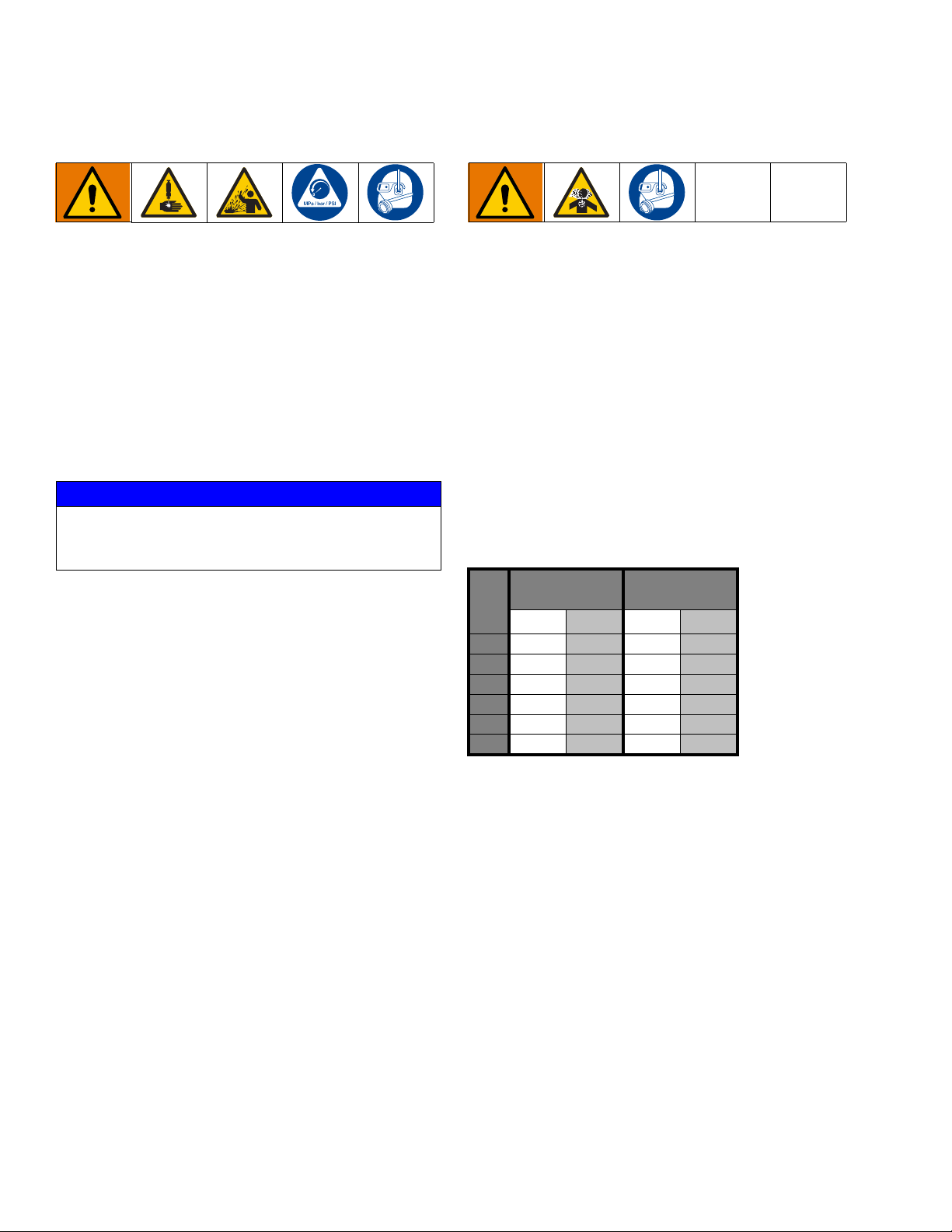
Warnings
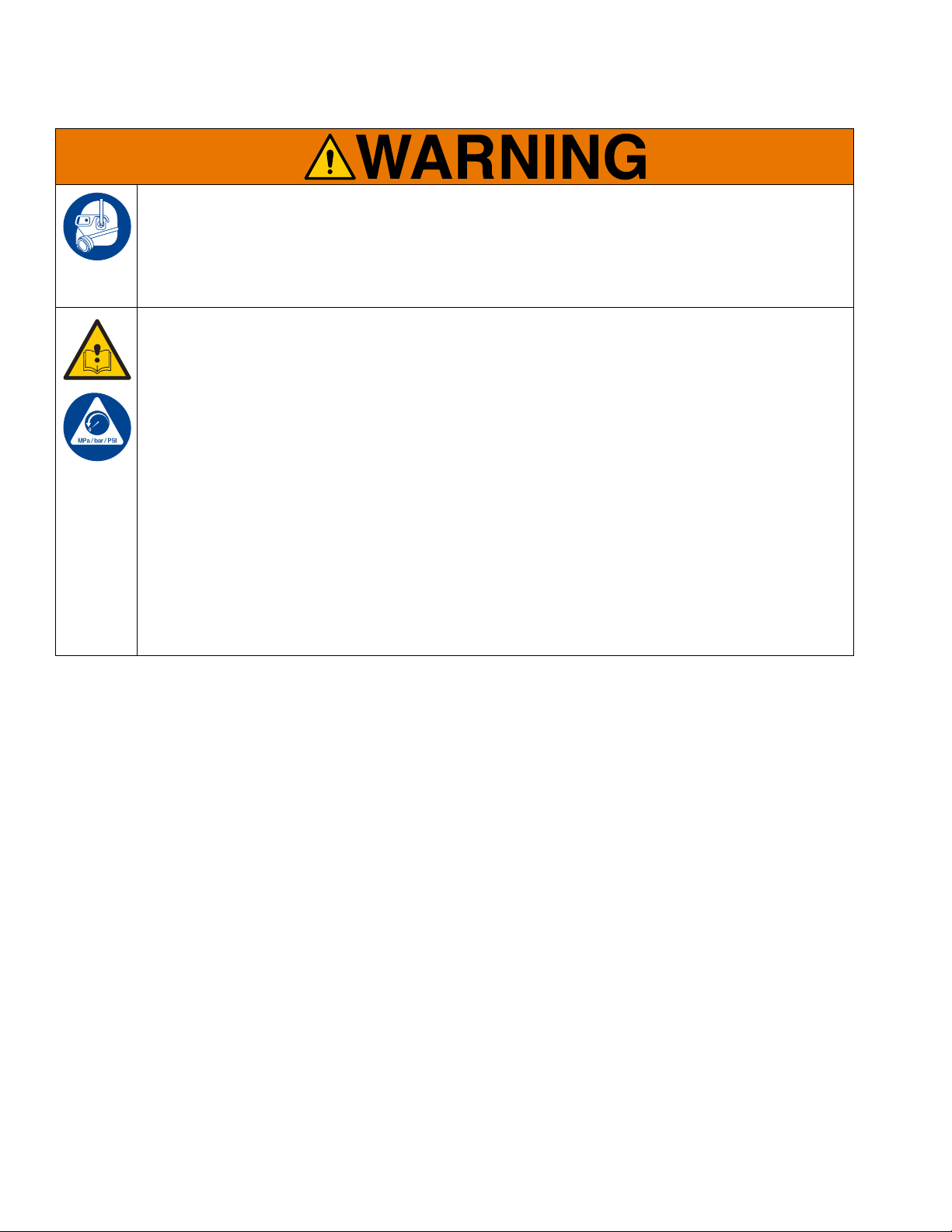
PERSONAL PROTECTIVE EQUIPMENT
Wear appropriate protective equipment when in the work area to help prevent serious injury, including
eye injury, hearing loss, inhalation of toxic fumes, and burns. Protective equipment includes but is not
limited to:
• Protective eyewear, and hearing protection.
• Respirators, protective clothing, and gloves as recommended by the fluid and solvent manufacture r.
EQUIPMENT MISUSE HAZARD
Misuse can cause death or serious injury.
• Do not operate the unit when fatigued or under the influence of drugs or alcohol.
• Do not exceed the maximum working pressure or temperature rating of the lowest rated system component. See Technical Data in all equipment manuals.
• Use fluids and solvents that are compatible with equipment wetted parts. See Technical Data in all
equipment manuals. Read fluid and solvent manufacturer’s warnings. For complete information
about your material, request Safety Data Sheet (SDS) from distributor or retailer.
• Turn off all equipment and follow the Pressure Relief Procedure when equipment is not in use.
• Check equipment regularly. Repair or replace worn or d amaged parts immediately with genuine manufacturer’s replacement parts only.
• Do not alter or modify equipment. Alterations or modifications may void agency approvals and create
safety hazards.
• Make sure all equipment is rated and approved for the environment in which you are using it.
• Use equipment only for its intended purpose. Call your distributor for information.
• Route hoses and cables away from traffic areas, sharp edges, moving parts, and hot surfaces.
• Do not kink or over bend hoses or use hoses to pull equipment.
• Keep children and animals away from work area.
• Comply with all applicable safety re gu la tion s.
6 3A6831A
Page 7
Installation
If using a flammable gas to drive the motor, to reduce
the risk of fire or explosion, route the exhaust away
from all sources of ignition. See Route Exhaust to
Remote Location on page 9.
NOTE: A small amount of the exhaust is not recover-
able, and will vent to atmosphere at the pump. However, a 100% Exhaust Capture Kit, B32651, is
available.
To reduce the risk of injury from ejected ice, do not
operate the motor without a plumbed exhaust line or
muffler installed.
Installation must comply with all local codes and regulations.
Grounding
The equipment must be grounded to reduce the risk
of static sparking. Static sparking can cause fumes to
ignite or explode. Grounding provides an escape wire
for the electric current.
Pump: ground through electrically conductive pneumatic and fluid lines.
Installation
Required Accessories
Install the following required accessories in the order
shown in F
Pneumatic Line
• Bleed-type master pneumatic valve (D): required
in your system to relieve air/gas trapped between it
and the pneumatic motor when the valve is closed.
• Be sure the valve is easily accessible from the
• Pump pneumatic regulator (E): to control pump
speed and outlet pressure. Locate it close to the
pump.
• Pneumatic line filter (C): removes harmful dirt and
moisture from compressed air/gas supply.
• Second bleed-type pneumatic valve (pneumatic
shutoff valve) (B): isolates pneumatic line accessories for servicing. Locate upstream from all other
pneumatic line accessories.
Fluid Line
• Fluid filter (Y-Strainer) (included in G): with a 60
mesh (250 micron) stainless steel element to filter
particles from the fluid before in reaches the pump.
IG. 1, using adapters as necessary.
pump and located downstream from the pneumatic regulator.
Pneumatic and fluid lines: use only electrically conductive lines.
Air compressor: follow manufacturer’s recommendations.
Fluid supply container: follow local code.
3A6831A 7
• Fluid shutoff valve (H): shuts off fluid flow.
• Pressure relief valve (J): overload protection.
Flush Before Using Equipment
The equipment was tested with lightweight oil, which is
left in the fluid passages to protect parts. To avoid contaminating your fluid with oil, flush the equipment with a
compatible solvent before using the equipm en t. See
Flush the Equipment, page 11.
Page 8
Installation
A
C
E
D
R
F
J
K
H
G
L
M
N
H
P
S
B
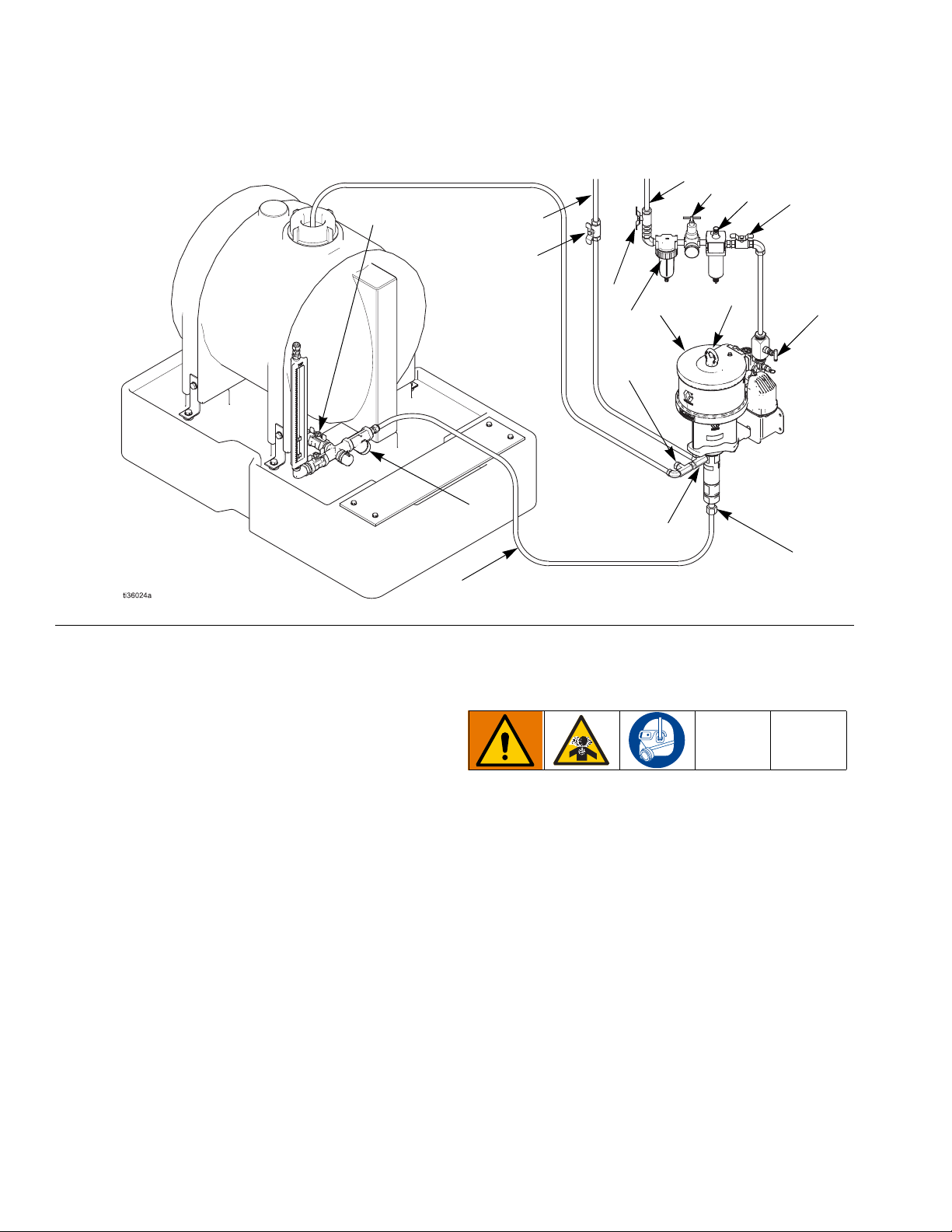
Typical Installation
FIG. 1:
FIG. 1 is an example of an installation with a Python
XL-DA25 chemical injection pump. Your installation may
differ from what is shown here. (See Required Acces-
sories, page 7.) The Python XL-DA25 pump (F) and
pneumatic needle valve (B) are the only components in
IG. 1 supplied by Graco. All other components a re sup-
F
plied by customer.
Key:
A Main Pneumatic Supply Line
B Secondary Pneumatic Bleed-Type Valve
C Pneumatic Filter
D Primary Bleed-type Master Pneumatic Valve
E Pneumatic Pressure Regulator
FPump
G Manifold Assembly (includes y-strainer and fluid shutoff
valve (H))
H Fluid Shutoff Valve (inlet & outlet)
J Fluid Pressure Relief Valve
K Fluid Inlet Line
LInlet Port
MOutlet Port
N Pneumatic Lubricator
P Fluid Outlet Line
R Speed Control Valve
S Lift Ring (for lifting the pump only)
Mount the Pump and Connect
Chemical Supply
The pump can be bolted to a wall or skid by the attached
bracket.
NOTE: The pump must always be mounted vertically.
If you have an application, or mounting configuration,
that requires installation in a manner different than
depicted in F
for assistance.
NOTE: A y-strainer (G) or chemical filter is required
before the pump inlet. This will keep any debris from the
IG. 1, please contact your Graco distributor
tank from reaching the pump seals. Fluid filter s ar e
available from Graco.
1. Mount the pump (F) and connect the fluid inlet
line (K).
8 3A6831A
Page 9
Installation
Connect Pneumatic Supply
1. Install the pneumatic regulator (E) and gauge to
control the inlet pressure. See Models on page 3 for
your model’s maximum pneumatic pressure.
NOTE: If less than 100 psi supply pressure is used, the
pump’s maximum output pressure will be decreased
proportionally.
Minimum Pneumatic Pressure can be found by first finding the table that corresponds to the plunger size (see
Minimum Pneumatic Pressures by Fluid Plunger
Size and Outlet Pressures on page 10). Next, using
the column that corresponds to the pneumatic motor
size, find the row equal to or slightly greater than the
outlet pressure of the pump. The value is the Minimum
Pneumatic Pressure required to achieve the fluid outlet
pressure.
2. Install a pneumatic line filter (C) to keep debris from
affecting pump performance and to increase pump
life.
NOTE: Keep the needle valve (B) closed at this point to
keep the pump from operating without fluid, which minimizes seal wear.
Connect Chemical Outlet
1. Connect a fluid line from the pump outlet port (M) to
the injection point.
2. Install a fluid pressure relief valve (J) on the outlet
side of the pump.
NOTE: A pressure relief valve is available from Graco
and can be connected back to the tank or directly to th e
inlet side of the pump. See Kits and Accessories on
page 35.
In the event of an injection line blockage, to reduce the
risk of skin injection and damage to the pump, ensure
the pressure relief valve is set at or below the maximum working pressure of the pump.
3. Set the pressure relief valve at or below the maximum working pressure of the pump.
3. Attach a pneumatic line to th e 1/ 4 in. fe ma le NPT
port on the needle valve (B).
Route Exhaust to Remote
Location
Replace the muffler (18) with a pneumatic line to route
exhaust to a remote location.
NOTICE
Due to the operational design of the pneumatic valve,
a small amount of the exhaust is not recoverable, a nd
will vent to atmosphere. However, a 100% Exhaust
Capture Kit, B32651, is available.
3A6831A 9
Page 10
Installation
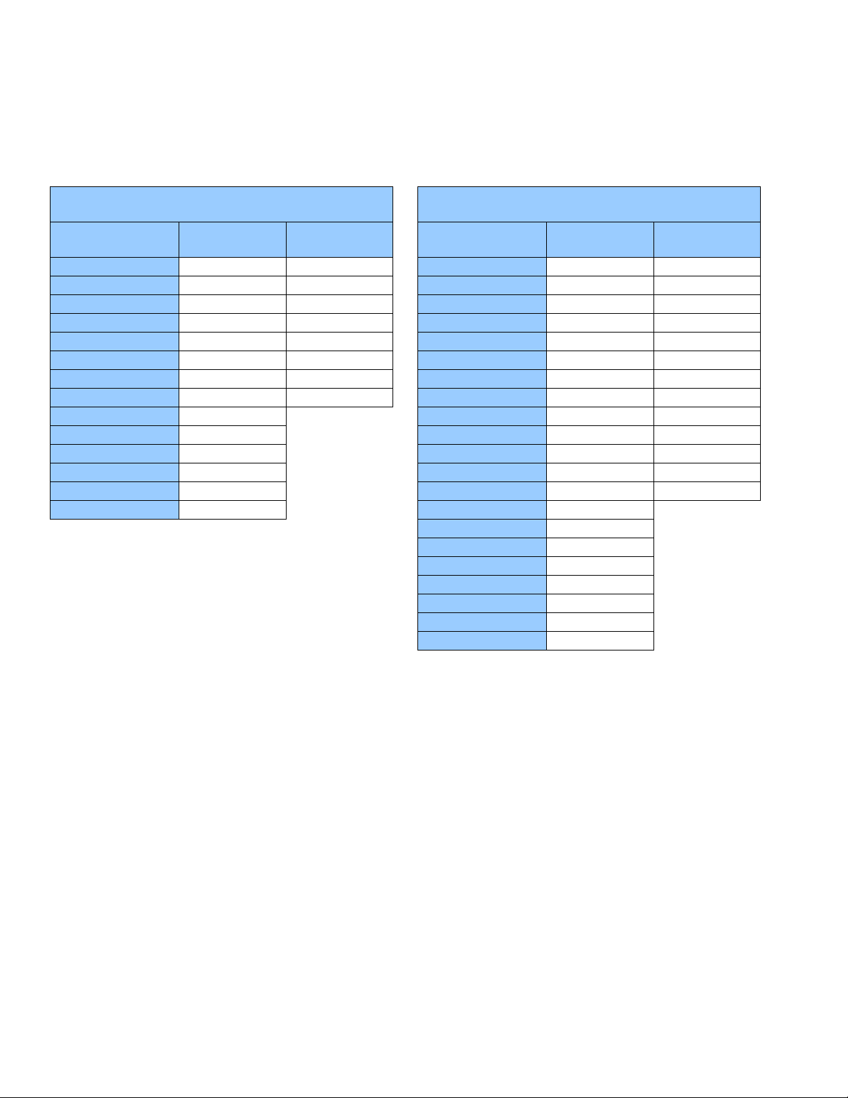
Minimum Pneumatic Pressures by Fluid Plunger Size and Outlet Pressures
Actual running pressure must be set in field to avoid stalling. See Performance Charts, starting on page 39, for maximum flows at any given pressure.
0600 (6.0 in) Pneumatic Motor Minimum Gas Pressure
psi (MPa, bar)
Outlet Pressure psi
(MPa, bar)
0 (0, 0) 15.0 (0.1, 1.0) 15.0 (0.1, 1.0)
500 (3.4, 34.5) 15.0 (0.1, 1.0) 15.0 (0.1, 1.0)
1000 (6.9, 68.9) 15.6 (0.1, 1.1) 26.3 (0.2, 1.8)
1500 (10.3, 103.4) 23.4 (0.2, 1.6) 39.5 (0.3, 2.7)
2000 (13.8, 137.9) 31.3 (0.2, 2.2) 52.6 (0.4, 3.6)
2500 (17.2, 172.4) 39.1 (0.3, 2.7) 65.8 (0.5, 4.5)
3000 (20.7, 206.8) 46.9 (0.3, 3.2) 79.0 (0.5, 5.4)
3500 (24.1, 241.3) 54.7 (0.4, 3.8) 92.1 (0.6, 6.4)
4000 (27.6, 275.8) 62.5 (0.4, 4.3)
4500 (31.0, 310.3) 70.3 (0.5, 4.8)
5000 (34.5, 344.7) 78.1 (0.5, 5.4)
5500 (37.9, 379.2) 85.9 (0.6, 5.9)
6000 (41.4, 413.7) 93.8 (0.6, 6.5)
6400 (44.1, 441.3) 100.0 (0.7, 6.9)
3/4 Inch
Fluid Plunger
1 Inch
Fluid Plunger
0750 (7.5 in) Pneumatic Motor Minimum Gas Pressure
psi (MPa, bar)
Outlet Pressure psi
(MPa, bar)
0 (0, 0) 15.0 (0.1, 1.0) 15.0 (0.1, 1.0)
500 (3.4, 34.5) 15.0 (0.1, 1.0) 15.0 (0.1, 1.0)
1000 (6.9, 68.9) 15.0 (0.1, 1.0) 16.4 (0.1, 1.1)
1500 (10.3, 103.4) 15.0 (0.1, 1.0) 24.6 (0.2, 1.7)
2000 (13.8, 137.9) 20.0 (0.1, 1.4) 32.8 (0.2, 2.3)
2500 (17.2, 172.4) 25.0 (0.2, 1.7) 41.0 (0.3, 2.8)
3000 (20.7, 206.8) 30.0 (0.2, 2.1) 49.2 (0.3, 3.4)
3500 (24.1, 241.3) 35.0 (0.2, 2.4) 57.4 (0.4, 4.0)
4000 (27.6, 275.8) 40.0 (0.3, 2.8) 65.6 (0.5, 4.5)
4500 (31.0, 310.3) 45.0 (0.3, 3.1) 73.8 (0.5, 5.1)
5000 (34.5, 344.7) 50.0 (0.3, 3.4) 82.0 (0.6, 5.7)
5500 (37.9, 379.2) 55.0 (0.4, 3.8) 90.2 (0.6, 6.2)
6000 (41.4, 413.7) 60.0 (0.4, 4.1) 98.4 (0.7, 6.8)
6500 (44.8, 448.2) 65.0 (0.4, 4.5)
7000 (48.3, 482.6) 70.0 (0.5, 4.8)
7500 (51.7, 517.1) 75.0 (0.5, 5.2)
8000 (55.2, 551.6) 80.0 (0.6, 5.5)
8500 (58.6, 586.1) 85.0 (0.6, 5.9)
9000 (62.1, 620.5) 90.0 (0.6, 6.2)
9500 (65.5, 655.0) 95.0 (0.7, 6.6)
10,000 (68.9, 689.5) 100.0 (0.7, 6.9)
3/4 Inch
Fluid Plunger
1 Inch
Fluid Plunger
For applications where the exhaust is ported to
a pressurized location, compute the difference
between the inlet and outlet pressures to get
the pneumatic pressure to be used in the
above tables. Minimum pressure differential is
15 psi (0.1 MPa, 1.0 bar).
10 3A6831A
Page 11
Operation
Operation
Pressure Relief Procedure
Follow the Pressure Relief Procedure whenever
you see this symbol.
This equipment stays pressurized until pressure is
manually relieved. To help prevent serious injury from
pressurized fluid, such as skin injection and splashing
fluid, follow the Pressure Relief Procedure when
you stop dispensing and before cleaning, checking, or
servicing the equipment.
NOTE: Always discharge fluid into an approved container or location.
1. Shut off all fluid and pneumatic lines (A, K, & P)
using the two fluid shutoff valves (H) and the pneumatic needle valve (B).
2. Slowly loosen the fluid lines to (K & P) at the pump
outlets (L & M) to bleed off any residual pressure.
3. Disconnect the fluid lines (K & P) from pump outlets
(L & M).
Flush the Equipment
To avoid fire and explosion, always ground equipment
and waste container. To avoid static sparking and
injury from splashing, always flush at the lowest possible pressure.
• Flush with a fluid that is compatible with the fluid
being dispensed and the equipment wetted parts.
1. Follow the Pressure Relief Procedure.
2. Connect the inlet port to the flushing fluid supply
source.
3. Connect the outlet port to the waste reservoir.
4. Run the pump until the dispensed fluid is predominately flushing fluid.
5. Follow the Pressure Relief Procedure.
3A6831A 11
Page 12
Operation
Prime the Pump
1. Verify all connections and fluid lines are tight.
NOTE: The pressure regulator (E) and inlet pneumatic
needle valve (B) both effect the pump cycle rate. After
inlet pressure is set, the needle valve can serve as a
speed control.
2. Adjust pneumatic regulator (E) to desired pressure.
3. Open bleed-type pn eu m at ic valv e (D) . Slowly turn
pump needle valve (B) counter-clockwise, increasing air/gas flow to the pump.
NOTICE
Pump runaway may occur if the needle valve (B) is
opened too far for pressure settings, causing damage
to the packing sets (102 and 107).
4. Keep the pump cycle rate less than 1 cycle every 3
seconds only while priming the pump.
Calibrate Chemical Dosage
1. Set the pump to an estimated setting of the flow
rate.
2. Follow the instructions provided with your calibration
gauge.
3. Adjust the cycle rate with the inlet pneumatic needle
valve (B) and/or the pressure regulator (E).
4. Repeat the steps 2 and 3 to verify your changes.
Repeat as necessary until the desired flow rate is
achieved.
Baseline Chemical Dosage Settings
See Performance Charts, starting on page 39, for maximum flows at any given pressure.
Plunger Pumps
CPM
10
20
30
40
50
60
3/4 in. Fluid
GPD LPD GPD LPD
180 680 269 1017
359 1360 537 2033
539 2041 806 3050
719 2721 1074 4066
899 3401 1343 5083
1078 4081 1611 6100
1 in. Fluid
Plunger Pumps
NOTE: Maximum cycle rate is 60 CPM (cycles per min-
ute), and the minimum cycle rate is 10 CPM. All values
are at 0 psi back pressure. Cycle rates over 60 may
cause excess wear and premature seal failure.
12 3A6831A
Page 13

Maintenance
Preventive Maintenance
Schedule
The operating conditions of your particular pump determines how often maintenance is required. Establish a
preventive maintenance schedule by recording when
and what kind of maintenance is needed, and then
determine a regular schedule for checking your pump.
Tighten Threaded Connections
Check that all threaded connections are tight at routine
intervals.
Tighten Packings
Maintenance
The packings included in your pump have the ability to
be adjusted to stop leaks that develop when the seals
are worn. If a leak develops in the pump’s fluid section,
tighten the packing nut clockwise by 1/16 of a turn, or
lower, until the leak is eliminated. The life of the packing
can be affected by over-tightening the packings. If the
packing nut needs to be tightened repeatedly after short
intervals, replace the packing.
Storage
If the pump is going to be stored for long periods, it is
recommended that the pump be flushed with a
light-weight oil or rust prohibiter to protect pump components. Store the pump with protective fluid inside whenever possible.
3A6831A 13
Page 14

Troubleshooting
Troubleshooting
1. Follow Pressure Relief Procedure, page 11,
before checking or repairing pump.
2. Check all possible problems and causes before disassembling pump.
Problem Cause Solution
Air bubbles in fluid. Fluid inlet line is loose. Tighten.
Fluid leaking. Loose fittings. Tighten fittings.
Worn seals. Adjust packing (if leak persists, replace
packing).
Pump stroking, but no fluid moving. Air in pump. Prime pump.
Worn or damaged check valve seals. Rebuild top and bottom poppets.
Pneumatic motor will not run. Damaged pneumatic valve (217). Replace or service pneumatic valve (217).
See page 19.
Damaged pilot valve (219). Replace pilot valves (219).
See page 22.
Air continuously exhausting around
pneumatic motor plunger.
Air continuously exhausting from muffler. Damaged pneumatic valve plate (305) or
Pneumatic motor “bounces” at top of
stroke.
Pneumatic motor “bounces” at bottom of
stroke.
Icing inside motor. Pneumatic motor operating at high
Damaged u-cups (203). Replace plunger u-cups (203).
See page 25.
Replace or service pneumatic valve (217).
cup (312).
Damaged bottom pilot valve (219). Replace bottom pilot valve (219). See
Damaged top pilot valve (219). Re place top pilot valve (219).
pressure or high cycle rate.
See page 19.
page 22.
See page 22.
Reduce pressure, cycle rate, or duty cycle
of motor.
Reduce dew point of compressed air in
moisture coalescing filter.
Pump fails to operate. Restricted line or inadequate air/gas
supply; closed or clogged valves.
Obstructed fluid line; fluid line ID is too
small.
Pump operates but does not prime. Held open or worn check valves or
packings.
Pump operates, but output is low on both
strokes.
Pump operates, but output is low on
downstroke.
Erratic or accelerated pump speed. Exhausted fluid supply. Refill and prime.
Fluid being pumped is visible on the packing nut.
14 3A6831A
Restricted line or inadequate air/gas
supply; closed or clogged valves.
Obstructed fluid line; fluid line ID is too
small.
Worn packings in pump. Replace packings. See page 16.
Held open or worn check valves or
packings.
Held open or worn check valves or
packings.
Worn packings. Tighten packing nut.
Clear line or increase air/gas supply.
Check that the valves are open.
Open, clear*; use line with larger ID.
Clear valve; replace packings.
See page 16.
Clear line or increase air/gas supply.
Check that the valves are open.
Open, clear*; use line with larger ID.
Clear valve; replace packings.
See page 16.
Clear valve, replace packings.
See page 16.
Replace packings. See page 16.
Page 15

Repair - Pump Lower
15
16
11
206
11
10
Before servicing or repairing your pump, verify that
pressure is relieved according to the Pressure Relief
Procedure, page 11, and that all fluid and pneumatic
lines are properly shut off, or sealed with compat ible
valves and disconnected.
• Always use Genuine Graco Parts an d Acce ss or ies,
available from your Graco distributor. If you supply
your own accessories, be sure they are adequately
sized and pressure rated for your system.
Disconnect the Pump Lower
Repair - Pump Lower
5. Hold the drip shield (4) out of the way if it is blocking
the pneumatic motor plunger (206). Hold the flats of
the pneumatic motor plunger (206) with a wrench.
Use another wrench to loosen the coupler nut (11).
Threads are very sharp. Use a rag to protect hands
when turning or carrying the pump.
1. Stop the pump in the middle of the stroke.
2. Follow the Pressure Relief Procedure, page 11.
3. Disconnect the fluid lines.
4. Loosen the screw (16) and remove the tie rod shield
(15). The drip shield (4) may slide down the tie ro ds
once the rod shield is removed.
FIG. 3
6. Lower the coupler nut (11) enough to remove the
coupling collars (10), and then remove the coupler
nut (11).
FIG. 4
FIG. 2
3A6831A 15
Page 16

Repair - Pump Lower
9
119
206
118
118
116
114
115
117
109
113
101
7. Use a hammer and brass rod to loosen the jam
nut (119). Unscrew the jam nut as far as possible.
FIG. 5
8. Unscrew the pump lower (9) by hand and place on
work bench.
Pump Repair
1. Remove the lower fluid cylinder (113) and cylinder
cap (117) assembly from the primary fluid cylinder
(101).
FIG. 6
2. Remove the cylinder cap (117) from the lower fluid
cylinder (113).
3. Remove the plunger (109).
4. Remove the cylinder cap check valve retainer (116)
and cylinder cap check valve poppet (114).
16 3A6831A
Page 17

Repair - Pump Lower
109
107
108
110
111
112
Primary
Seal Stack (102)
Secondary
Seal Stack (107)
103
108
106
105
103
102
101
119
FIG. 7
5. Remove the plunger check valve seat (112) and
plunger check valve poppet (110).
6. Remove the o-rings (118) from the lower fluid cylinder (113).
7. Remove the bearing (108) and secondary seal
stack (107) from the fluid cylinder (101).
8. Remove the packing nut (106), shim (105), bearing
(103) and primary seal stack (102) from the fluid cylinder (101).
FIG. 8
9. Install the new primary seal stacking (102) including
bearing (103). Use grease during installation.
10. Install the packing nut (106) with pipe sealant until
finger tight.
FIG. 9
11. Install the new secondary seal stack (107), including
bearing (108). Use grease during installation.
3A6831A 17
Page 18

Repair - Pump Lower
11
10
109
206
6
5
109
11
206
12. Install two new o-rings (118) on the lower fluid cylin der (113). Orientation does not matter for this part.
13. Apply anti-seize to both lower fluid cylinder (113)
threads and install into the fluid cylinder (101).
Torque to 100 ft-lb.
14. Inspect and replace the plunger o-ring (111), as
required, and insert the plunger poppet (110) into
the plunger (109) in the direction shown. Apply
medium strength (blue) thread locker to the check
seat (112). Torque to the following values depending on the size of your pump lower:
Pump Lower Size Torque
075 40 ft-lb (54 N•m)
100 90 ft-lb (122 N•m)
15. Apply petroleum-based lubricant to the fluid p lunger
(109) and install into the fluid cylinder (101).
16. Inspect and replace the cylinder o-ring (115), as
required, and insert the cylinder poppet (114) into
the cylinder cap (117) in the direction shown. Install
the check retainer (116). Torque to 10 ft-lb
(14 N•m).
17. Install the cylinder cap (117) onto the lower fluid cylinder (113). Torque to 100 ft-lb (136 N•m).
18. Install the packing nut shim (105) and torque the
packing nut (106) to 20 ft-lb (27 N•m).
Reconnect the Pump Lower
1. Tilt the pneumatic motor (1) onto its back, then hand
turn the pump lower (9) into the adapter plate (6).
Set the pump upright again.
FIG. 10
3. Put the coupling collars (10) into the coupler nut
(11) so the large flanges point upward.
4. Gently let the pneumatic motor plunger (206) drop
onto the fluid plunger (109). Hand tighten the coupler nut (11).
5. Screw the pump lower (9) into the adapter nut (5)
until the cylinder top is flush with the top of the
adapter plate (6).
2. Hold the pneumatic motor plunger (109) up with one
hand. With your other hand, put th e coupler nut ( 11)
on the plunger.
18 3A6831A
FIG. 11
6. Align the fluid outlet as shown and tighten the jam
nut.
7. Hold the flats of the motor plunger (206) with a
wrench. Use another wrench to tighten the coupler
nut (11). Torque the coupler nut (11) to 75-80 ft-lbs
(102-108 N•m).
8. Hold the drip shield (4) out of the way and replace
the tie rod shield (15).
Page 19

Repair - Pneumatic Motor
Repair - Pneumatic Motor
Replace Seals or Rebuild Pneumatic Valve
Inspect and replace seals and worn parts while disassembling and reassembling the pneumatic valve on the
next following pages.
Pneumatic Valve
Replace Complete Pneumatic Valve
1. Stop the pump. Follow Pressure Relief Procedure,
page 11.
2. Disconnect the pneumatic line to the motor.
3. See the figure on page 31. Remove four screws
(218). Remove the pneumatic valve (217) an d ga sket (216*).
4. To repair the pneum at ic valve , go to Disassemble
the Pneumatic Valve, page 19. To install a replacement pneumatic valve (217), continue with step 5.
5. Align the new pneumatic valve gasket (216*) on
the manifold, then attach the pneumatic valve (217).
Torque screws (218) to 95-105 in-lb (11-12 N•m).
6. Reconnect the pneumatic line to the motor.
IG. 12 and the following table to identify the kits
Use F
needed for replacements:
Symbol Kit Description
† Pneumatic Valve Seal Kits. See page 34
Pneumatic Valve Repair Kits. See page 34.
Pneumatic Valve End Cap Kits. See
page 34.
Disassemble the Pneumatic Valve
1. Perform steps 1-3 under Replace Complete Pneumatic Valve, page 19.
2. See F
3. See F
IG. 12. Use a 2 mm or 5/64 in. hex key to
remove two screws (309†). Remove the valve
plate (305), cup (312), and spring (311).
IG. 12. Remove the snap ring (310) from
each end. Use the piston to push the end caps
(307) out of the ends. Remove end cap o-rings
(306†).
4. Remove the piston (302). Remove the u-cup seals
(308†) from each end, and the detent assembly
(303) and detent cam (304) from the center.
3A6831A 19
Page 20

Repair - Pneumatic Motor
1
Apply lubricant.
310
307
307
†309
305
312
311
303
302
†308
†
308
301
304
310
ti16213a
†321
†321
313
314
1
1
1
1
1
1
1
1
FIG. 12
20 3A6831A
Page 21

Repair - Pneumatic Motor
Lips face down
Lips face up
†308
†308
302
ti12754a
312
ti16283a
Magnet
Reassemble the Pneumatic Valve
1. See F
IG. 12. Lubricate detent cam (304) and
install into housing.
2. See F
IG. 13. Lubricate the u-cups (308†) and
install on the piston (302) with lips facing toward
the center of the piston.
7. Install the spring (311). Lubricate and install the
pneumatic valve cup (312), see F
IG. 14. Align the
small round magnet with the pneumatic inlet.
8. Install the valve plate (305). Tighten the screws
(309†) to hold it in place.
FIG. 14
F
3. See F
4. Lubricate and install the detent assembly (303)
5. Lubricate new o-rings (306†) and install on the
6. Install a snap ring (310) on each end to hold end
9. Perform steps 5 and 6 under Replace Complete
Pneumatic Valve, page 19.
IG. 13
IG. 12. Lubricate both ends of the piston
(302) and install it in the housing.
into the piston.
end caps (307). Install the end caps into the housing.
caps in place.
3A6831A 21
Page 22

Repair - Pneumatic Motor
15
16
15
4
3
Replace Pilot Valves
1. Stop the pump. Follow the Pressure Relief Procedure, page 11.
2. Disconnect the pneumatic line to the motor.
3. Loosen the screw (16) and remove the tie rod
shield (15).
FIG. 15
4. Slide the drip shield (4) down on the tie rods (3).
FIG. 16
5. Use a 10 mm socket wrench to remove the old pilot
valves (219) from the top (213) and bottom (201)
covers. See the figure on page 31.
6. Lubricate and install the new pilot valves (219).
Torque to 95-105 in-lb (11-12 N•m).
7. Slide the drip shield (4) to the top of the tie rods (3)
and replace the tie rod shield (15).
8. Reconnect the pneumatic line to the motor.
22 3A6831A
Page 23

Repair Pneumatic Motor
15
16
11
206
14
NOTE: Pneumatic Motor Seal Kits are available. See
Kits and Accessories, page 35, for the correct kit for
your motor. For best results, use all parts in the kit.
Disconnect the Pneumatic Motor
1. Flush the pump, if possible. (See package manual.)
Follow the Pressure Relief Procedure, page 11.
2. Disconnect the pneumatic and fluid hoses, and the
ground wire.
3. Loosen the screw (16) and remove the tie rod shield
(15). The drip shield (4) may slide down the tie ro ds
once the rod shield is removed. (See F
IG. 16.)
Repair - Pneumatic Motor
FIG. 18
FIG. 17
4. Hold the drip shield (4) out of the way if it is blocking
the pneumatic motor plunger (206). Hold the flats of
the pneumatic motor plunger (206) with a wrench.
Use another wrench to loosen the coupler nut (11).
5. Remove the tie rod nu ts (8 ).
6. Use a socket wrench to remove the mounting
screws (14).
F
IG. 19
7. Lift up on the pneumatic motor to remove it. The tie
rods (3) and drip shield (4) will remain attached.
3A6831A 23
Page 24

Repair - Pneumatic Motor
ti12749a
ti12750a
3*
43*
ti12755a
Lips face up
U-cup faces up.
Flange faces down.
Disassemble the Pneumatic Motor
1. Use a 10 mm socket wrench to remove the four
screws (218), and remove the pneumatic valve
(217) and gasket (216).
2. Remove the mufflers (18).
3. Remove the four screws (218), and remove the
manifold (215) and two gaskets (214).
4. Use a 10 mm socket wrench to remove the pilot
valves (219), and the top and bottom covers (213
and 201).
5. Remove the 17 mm tie bolts (21 0). Th e nu m be r of
bolts depends on your configuration.
Configuration
PCI-0600-xxx-xxx-xx-x-x
Reassemble the Pneumatic Motor
NOTE: For easier reassembly, start with the top
cover (213) turned over on the workbench and assemble the pneumatic motor upside-down.
1. Lubricate and install the o-ring (209) on the top
cover (213).
2. Install the upper bumper (228) on the top cover.
3. Lubricate the inside of the cylinder (211). Lower the
cylinder onto the top cover (213).
4. Lubricate and install the o-ring (208) around the piston (205).
5. Slide the piston assembly down onto the
cylinder (211). Be sure the o-ring (208) stays in
place.
6. Install the shield (212) around the cylinder (211) and
in the groove on the top cover (213).
7. Lubricate and install the new u-cup seal in the bottom of the bearing (202) in the bottom cover (201).
The u-cup must face up and the flange face down.
IG. 21.
See F
PCI-0750-xxx-xxx-xx-x-x
6. Remove the top cover (213) and the o-ring (209).
7. Remove the shield (212) from around the
cylinder (211), and remove the cylinder.
8. Slide the piston assembly straight up off the bottom
cover (201).
NOTE: There is no need to take apart the piston assembly. If any part is worn or damaged, the entire assembly
should be replaced.
9. Remove the o-ring (208) from around the piston
(205).
10. Remove the retaining ring (204), u-cup seals (203),
and the o-ring (209) from the bottom cover (201).
FIG. 20
8. Lubricate and install the new u-cup seal (203) in the
top of the bearing. Lips must face up.
9. Lubricate and install the o-ring (209) in the bottom
cover (201).
10. Install the piston bumper (228) on the bottom
cover (201).
24 3A6831A
Page 25

Repair - Pneumatic Motor
ti14544a
201
206
211
213
212
11. Carefully place the bottom cover (201) on the cylinder (211), sliding the rod (206) through the be a ring
(202). The manifold surfaces of the top and bottom
covers must align. Be sure the shield (212) is in the
groove on both the top and bottom covers.
Reconnect the Pneumatic Motor
1. Replace the motor on the mounting bracket (2).
2. Screw the tie rods (3) into the motor, with the top
hex nuts (4) attached. Torque the tie rods to 5-10
ft-lb (7-13 N•m).
NOTE: Always tighten the tie rods (3) before tightening
the top hex nuts (4).
3. Tighten the top hex nu ts (4 ) to se cur e the mou nt ing
bracket (2).
4. Slide the pump with the adapter plate (6) attached
onto the tie rods (3).
5. Install the tie rod nuts (8). Torque to 100 in-lb
(11 N•m).
6. Align the hole in the fluid plunger (109) with the hole
in the pneumatic motor plunger (206).
7. Slide the drip shield (4) to the top of the tie rods (3)
and replace the tie rod shield (15).
IG. 21
F
12. Install the tie bolts (210) hand tight.
13. Install two gaskets (214) on the manifold (215), and
install the manifold. Torque bolts to 95-105 in-lb
(11-12 N•m). (The manifold is reversible for ease of
placement of the muffler or the remote exhaust.)
14. Align the pneumatic valve gasket (216) on the manifold (215), then attach the pneumatic valve (217).
15. Tighten the bolts (210) halfway. Work in a
criss-cross pattern while tightening the tie bolts.
Check that the shield remains in the grooves on
both covers. Continue tightening the bolts in pattern
and torque to 25-30 ft-lb (34-40 N•m).
16. Lubricate and install the pilot valves (219) in the top
and bottom covers. Torque to 5-105 in-lb (11-12
N•m).
17. Reinstall the mufflers (18).
18. See Reconnect the Pneumatic Motor on page 25.
8. Reconnect the pneumatic and fluid hoses, and the
ground wire.
3A6831A 25
Page 26

Repair - Pneumatic Motor
26 3A6831A
Page 27

Parts
1
18
17
26
27
26
24
25
22
23
12
13
14
2
15
10
4
11
3
5
6
7
9
8
16
119
32
Python XL-DA25 Pneumatic Pump
PCI-0750-050-075-XC-2-0 shown
Parts
3A6831A 27
Page 28

Parts
Python XL-DA25 Pump Parts List
Ref. Part Description Qty
1 B33007 Pneumatic motor, 6.0 in.;
PCI-0600-xxx-xxx-xx-2-x
B33008 Pneumatic motor, 7.5 in.;
PCI-0750-xxx-xxx-xx-2-x
2 B33100 Wall bracket 1
3 B33101 Motor tie rod 3
4 15V028 Drip shield 1
5 -- Lower adapter nut 1
6 B33102 Pump lower adapter;
PCI-xxxx-075-113-xx-2-x
B33111 Pump lower adapter;
PCI-xxxx-100-138-xx-2-x
7 -- Lock washer, 5/8 in.; stainless
steel; (included with ref. 3)
8 -- Hex nut; (included with ref. 3) 3
9See Pump
Lower Mod-
els, pg 35
10 B33103 Coupling collar; (pack of 10) 2
11 B33104 Coupler nut 1
12 -- Flat washer; (included with ref. 2) 4
13 -- Spring lock washer; (included with
14 -- Hex head screw; (included with
15 B33105 Shield 1
16 -- Screw, M4-.7, 10 mm; stainless
17 15U426 Reducing bushing, 3/4 in. nptf - 1/2
18 24D642 Muffler, 1050 AODD; ice resistant;
22 B33106 Bushing, 1/2 in. x 1/4 in. npt, mf, 1
23 B33107 Elbow fitting, 1/4 in. nptf x 1/4 in.
24 B33108 Tee fitting, 1/4 in. nptm-nptf-nptm 1
25 B33109 Safety valve, 110 PSI 1
26 B33110 Pipe bushing fitting, 1 in. x 1/4 in.
27 131295 Needle valve 1
32 15W719 Warning Safety Label 1
119 B33173 Jam nut, 3/4 in.;
B33174 Jam nut, 1 in.;
Pump lower 1
ref. 2)
ref. 2)
steel; (included with ref. 15)
in. nptm; (pack of 1)
(pack of 1)
nptm
npt; (pack of 1)
PCI-xxxx-075-113-xx-2-x
PCI-xxxx-100-138-xx-2-x
Replacement Danger and Warning labels, tags, and
cards are available at no cost.
1
1
1
1
3
4
4
1
2
2
1
2
1
1
28 3A6831A
Page 29

Pump Lower
101
102
103
106
105
109
107
108
118
110
111
112
113
118
117
116
115
114
104
123
Parts
3A6831A 29
Page 30

Parts
Pump Lower Parts List
PCI-xxxx-075-113-xx-2-x
Ref. Description
101 Fluid cylinder B33138 B33139 1
102 Primary seal stack See table below 1
103 Primary bearing B33136 B33137 1
104 Pellet (included with ref. 101) 1
105 Packing nut shim B3313 4 B33135 1
106 Packing nut B33132 B33133 1
107 Secondary seal stack See table below 1
108 Secondary bearing B33130 B33131 1
109 Fluid plunger B33128 B33129 1
110 Plunger poppet B33126 B33127 1
111 Plunger poppet o-ring See table below 1
112 Check seat B33124 B33125 1
113 Lower fluid cylinder B33122 B33123 1
114 Cylinder poppet B33120 B33121 1
115 Cylinder poppet o-ring See table below 1
116 Check retainer B33118 B33119 1
117 Cylinder cap B33116 B33117 1
118 O-ring packing; (pack of 10) B33114 B33115 2
119 Jam nut (shown on pg 27) B33112 B33113 1
123 Warning safety label 17G320 1
3/4 in. Part numbers
PCI-xxxx-100-138-xx-2-x
1 in. Part numbers Qty
Replacement Danger and Warning labels, tags, and cards are available at no cost.
Ref. Description Seal Material 3/4 in. 1 in.
C HNBR B33140 B33152
102 Primary Seal Stack
107 Secondary Seal Stack
111 Plunger Poppet O-ring
115 Cylinder Poppet O-ring
D FFKM B33141 B33153
E TFE/P B33142 B33154
C HNBR B33143 B33155
D FFKM B33144 B33156
E TFE/P B33145 B33157
C HNBR B33146 B33158
D FFKM B33147 B33159
E TFE/P B33148 B33160
C HNBR B33149 B33161
D FFKM B33150 B33162
E TFE/P B33151 B33163
30 3A6831A
Page 31

Pneumatic Motor Parts
201
210
242
228
209
202
203
204
206
205
208
212
209
213
237
243
219
229
230
211
214
227
216
217
218
218
219
221
215
PCI-0600, 6.0 in. (152.4 mm); PCI-0750, 7.5 in. (190.5 mm), shown
Parts
‡ These items are only available in Pneumatic Motor Kits B32251 and B32770
3A6831A 31
Page 32

Parts
Pneumatic Motor Parts List
Part number shown:
B33007 (PCI-0600): 6.0 in. (152.4 mm)
B33008 (PCI-0750): 7.5 in. (190.5 mm)
Ref. Part Description Qty
201 B33171 Lower cover; PCI-0600 1
B33172 Lower cover; PCI-0750 1
202 -- Bearing; (included with ref. 201) 1
203
204
205 24A550 Motor piston; PCI-0600 1
206 -- Piston Rod; (included with ref. 205) 1
208
209
210 B 33169 Hex cap screw; PCI-0600 4
211 15M672 Motor cylinder; PCI-0600 1
212 B33167 Bolt cover; PCI-0600 (includes
213 B33165 Upper cover; PCI-0600 1
-- U-cup packing 1
-- Retainer ring 1
16G515 Motor piston; PCI-0750 1
-- Packing o-ring; (included with ref. 205) 1
-- End cap o-ring 2
B33170 Hex cap screw; PCI-0750 6
16A516 Motor cylinder; PCI-0750 1
English warning label)
B33168 Bolt cover; PCI-0750 (includes
English warning label)
B33166 Upper cover; PCI-0750 1
Ref. Part Description Qty
214
215 24A580 Motor manifold 1
216
217 B33164 Pneumatic valve 1
218 -- Screw; M6; (included with ref. 215,
219 24A366 Pilot valve 2
221 -- Ball; (included with ref. 215, 24A580) 2
227 -- Expansion plug; (included with ref.
228 24A914 Bumper; PCI-0600 1
229 -- Upper bumper; (included with ref. 228,
1
230 -- Screw; M5; (included with ref. 228,
1
237 -- O-ring packing; (included with ref.
242
243 24E991 Hook 1
-- Manifold gasket; (included with ref.
215, 24A580)
17F429 Pneumatic valve gasket; (included
with ref. 215, 24A580)
24A580)
215, 24A580)
24A915 Bumper; PCI-0750 1
24A915)
24A915)
243)
-- Rod seal 1
2
1
8
2
1
3
1
Replacement Danger and Warning labels, tags, and cards are available at no cost.
Included in 6.0 in. Pneumatic Motor Seal Kit 24A547. See page 34.
Included in 7.5 in. Pneumatic Motor Seal Kit 24A551. See page 34.
32 3A6831A
Page 33

Pneumatic Valve Parts
310
307
307
309
305
312
311
303
302
308
308
301
304
310
ti16213a
321
321
313
314
Parts
3A6831A 33
Page 34

Parts
Pneumatic Valve Parts
Complete Pneumatic Valve Replacement Kit B33164
To replace the complete pneumatic valve, order Pneumatic Valve Replacement Kit B33164 (6 in. and 7 in.). The kit
includes items 301-312 below, and items 209 and 211 on page 32.
Pneumatic Valve Repair Kits
Pneumatic valve parts are not sold individually. The table below shows possible kit options for each part.
Pneumatic Valve
Ref. Description Qty.
301 Housing 1
302 Pneumatic valve piston 1
303 Detent piston 1
304 Detent cam 1
305 Pneumatic valve plate 1
307 Cap 2
308 U-cup packing 2
309 Screw; M3 2
310 Snap ring 2
311 Detent spring 1
312 Casting cup 1
313 Base cup 1
314 Casting cup gasket 1
321 O-ring packing 3
Replacement screws (309) are available in a pack of 10. Order Kit 24A359.
Repair Kit 24A538
Pneumatic Valve
Seal Kit 24A536
Pneumatic Valve
End Cap Kit 24A361
34 3A6831A
Page 35

Kits and Accessories
Kits and Accessories
Pump Lower Models Additional Kits & Accessories
Configuration
Part No.
B33016 075-113-XC-2
B33017 075-113-XD-2 FFKM
B33018 075-113-XE-2 TFE/P
B33022 100-138-XC-2
B33023 100-138-XD-2 FFKM
B33024 100-138-XE-2 TFE/P
Code
Lower
Size
3/4 in. Chromex
1 in. Chromex
Lower
Coating
Seal
Material
HNBR
HNBR
Part No. Description
B32045 225-750 PSI Pressure Relief Valve Kit
(Adjustable)
B32046 750-1500 PSI Pressure Relief Valve Kit
(Adjustable)
B32047 1500-2250 PSI Pressure Relief Valve Kit
(Adjustable)
B32048 2250-3000 PSI Pressure Relief Valve Kit
(Adjustable)
B32049 3000-4000 PSI Pressure Relief Valve Kit
(Adjustable)
B32050 4000-5000 PSI Pressure Relief Valve Kit
(Adjustable)
B32051 5000-6000 PSI Pressure Relief Valve Kit
(Adjustable)
HIP10RV 1000-10,000 PSI Pressure Relief Valve
Kit (Adjustable)
B32088 SST Calibration Column Kit
B32089 SST Manifold Assembly Kit
B32157 316 SST Ball Valve Kit, 3/4 in. NPT(F)
B32158 Fluid Filter 6000 PSI
B32159 Fluid Filter 10000 PSI
B32162 1/4 in. NPT(F) X 1/4 in. NPT(F) Check Kit;
10,000 PSI
3A6831A 35
Page 36

Dimensions
Dimensions
Python XL-DA25 Pump Dimensions
FIG. 22 Python Pump Dimensions
Size A B C D E
600 24.0 in.
(61.0 cm)
750 24.0 in.
(61.0 cm)
36 3A6831A
14.5 in.
(36.8 cm)
14.5 in.
(36.8 cm)
16.75 in.
(42.5 cm)
16.75 in.
(42.5 cm)
17.75 in.
(45.1 cm)
17.75 in
(45.1 cm)
8.0 in.
(20.3 cm)
8.0 in.
(20.3 cm)
Page 37

Wall Bracket Mounting Hole Diagram
2X 5.50
4X Ø .400
2.00
2.00
4X 6.936
2X 1.09
2X 8.59
4X 1.14
2.79
2.79
4X R 0.175
2X 1.000
2X 2.375
2X 11.00
Dimensions
3A6831A 37
Page 38

Dimensions
Four M8 X 1.25
optional
mounting holes
Two M8
mounting holes
Three 5/8-11
tie rod holes
5.906 in.
(150 mm)
bolt circle
ti12738a
ti12737a
3.38 in. (86 mm)
2.0 in. (50 mm)
5.250 in.
(133 mm)
4 in.
(102 mm)
Four M8 X 1.25
optional
mounting holes
Three 5/8-11
tie rod holes
5.906 in.
(150 mm)
bolt circle
Two M8
mounting holes
ti12740a
ti12739a
3.1 in. (78 mm)
5.250 in.
(133 mm)
3.1 in. (78 mm)
Pneumatic Mounting Hole Diagrams
PCI-0600 (6 in. motor)
FIG. 23
PCI-0750 (7.5 in. motor)
FIG. 24
38 3A6831A
Page 39

Performance Charts
0
0
200
(757)
400
(1514)
600
(2271)
800
(3028)
1000
(3785)
1200
(4542)
500
(34.5)
(3.45)
1000
(69.0)
(6.90)
1500
(103.4)
(10.34)
4500
(310.3)
(31.03)
0
10
20
30
40
50
60
AAB
B
C
C
D
D
E
E
2000
(137.9)
(13.79)
2500
(172.4)
(17.24)
3000
(206.8)
(20.68)
3500
(241.3)
(24.13)
4000
(275.8)
(27.58)
0
60
15
30
45
Inlet Pressure PSI (MPa, Bar)
A-15 (0.10, 1.0)
B-25 (0.17, 1.7)
C-50 (0.34, 3.4)
D-75 (0.52, 5.2)
E-100 (0.69, 6.9)
--- Fluid Flow
- - Air Flow
Flow -
GPD
(LPD)
Pressure - PSI (bar)(MPa)
Air Consumption
(SCFM)
Pump Speed
(cyc/min)
0
0
200
(757)
400
(1514)
600
(2271)
800
(3028)
1000
(3785)
1200
(4542)
1400
(5300)
1600
(6057)
1800
(6814)
500
(34.5)
(3.45)
1000
(69.0)
(6.90)
1500
(103.4)
(10.34)
0
10
20
30
40
50
60
AAB
B
C
C
D
D
E
E
2000
(137.9)
(13.79)
2500
(172.4)
(17.24)
3000
(206.8)
(20.68)
3500
(241.3)
(24.13)
0
60
15
30
45
Inlet Pressure PSI (MPa, Bar)
A-15 (0.10, 1.0)
B-25 (0.17, 1.7)
C-50 (0.34, 3.4)
D-75 (0.52, 5.2)
E-100 (0.69, 6.9)
--- Fluid Flow
- - Air Flow
Flow GPD
(LPD)
Pressure - PSI (bar)(MPa)
Air Consumption
(SCFM)
Pump Speed
(cyc/min)
6 in. Motors
3/4 in. Plunger (PCI-0600-075)
Performance Charts
FIG. 25
1 in. Plunger (PCI-0600-100)
FIG. 26
3A6831A 39
Page 40

Performance Charts
0
0
200
(757)
400
(1514)
600
(2271)
800
(3028)
1000
(3785)
1200
(4542)
1000
(69.0)
(6.90)
0
10
20
30
40
50
60
AAB
B
C
C
D
D EE
2000
(137.9)
(13.79)
3000
(206.8)
(20.68)
4000
(275.8)
(27.58)
6000
(413.7)
(41.37)
5000
(344.7)
(34.47)
7000
(482.6)
(48.26)
8000
(551.6)
(55.16)
0
60
15
30
45
Inlet Pressure PSI (MPa, Bar)
A-15 (0.10, 1.0)
B-25 (0.17, 1.7)
C-50 (0.34, 3.4)
D-75 (0.52, 5.2)
E-100 (0.69, 6.9)
--- Fluid Flow
- - Air Flow
Air Consumption
(SCFM)
Flow GPD
(LPD)
Pump Speed
(cyc/min)
Pressure - PSI (bar)(MPa)
0
0
200
(757)
400
(1514)
1000
(69.0)
(6.90)
2000
(137.9)
(13.79)
3000
(206.8)
(20.68)
4000
(275.8)
(27.58)
6000
(413.7)
(41.37)
5000
(344.7)
(34.47)
600
(2271)
800
(3028)
1000
(3785)
1200
(4542)
1400
(5300)
1600
(6057)
1800
(6814)
00
15
30
45
60
10
20
30
40
50
60
A
A
B
B
C
C
D
D
EE
Inlet Pressure PSI (MPa, Bar)
A-15 (0.10, 1.0)
B-25 (0.17, 1.7)
C-50 (0.34, 3.4)
D-75 (0.52, 5.2)
E-100 (0.69, 6.9)
--- Fluid Flow
- - Air Flow
Air Consumption
(SCFM)
Flow GPD
(LPD)
Pump Speed
(cyc/min)
Pressure - PSI (bar)(MPa)
7.5 in. Motors
3/4 in. Plunger (PCI-0750-075)
FIG. 27
1 in. Plunger (PCI-0750-100)
FIG. 28
40 3A6831A
Page 41

Technical Specifications
Technical Specifications
Python XL-DA25 Chemical Injection Pump
. . . . . . . . . . . . . . . . . . . . . . . . . . . . . . . . . . . . . . . US Metric
Maximum pneumatic inlet pressure See Models on page 3.
Maximum fluid working pressure See Models on page 3.
Maximum cycle rate 60 cpm
Environmental temperature range -40°– 176°F -40°– 80°C
Noise (dBa)
6.0 in. Pneumatic Motor Sound Power* 80.1 dBA
6.0 in. Pneumatic Motor Sound Pressure** 70.2 dBA
7.5 in. Pneumatic Motor Sound Power* 78.8 dBA
7.5 in. Pneumatic Motor Sound Pressure** 68.9 dBA
Inlet/Outlet Sizes
Fluid inlet size (3/4 in. plunger) 3/4 in. npt(m)
Fluid inlet size (1 in. plunger) 1 in. npt(m)
Fluid outlet size (3/4 in. and 1 in. plungers) 1/2 in. npt(f)
Pneumatic inlet size 1/4 in. npt(f)
Exhaust fitting size 1/2 in. npt(f)
Materials of Construction
See Configuration Number Matrix on page 4 for seal mate-
Pump/Check Valve Seal Material
Wetted Parts
Weight
6.0 in. Pneumatic Motor
0.75 in. lowers (CI-0600-075-113-xx-2-x) 57.5 lbs 26.1 kg
1.00 in. lowers (CI-0600-100-138-xx-2-x) 60.5 lbs 27.4 kg
7.5 in. Pneumatic Motor
0.75 in. lowers (CI-0750-075-113-xx-2-x) 62.5 lbs 28.3 kg
1.00 in. lowers (CI-0750-100-138-xx-2-x) 65.5 lbs 28.3 kg
rial. All other packing materials are PEEK and PTFE unless
otherwise noted.
See Configuration Number Matrix on page 4 for plunger
material. All other packing materials are 316 stainless steel
unless otherwise noted.
* Sound Power at 70 psi (0.48 MPa, 4.8 bar), 20 cpm. Sound power measured per ISO-9614-2.
** Sound Pressure was test 3.28 feet (1 m) from equipment.
3A6831A 41
Page 42

Graco Standard Warranty
Graco warrants all equipment referenced in this document which is manufactured by Graco and bearing its name to be free from defects in
material and workmanship on the date of sale to the original purchaser for use. With the exception of any special, extended, or limited warranty
published by Graco, Graco will, for a period of twelve months from the date of sale, repair or replace any part of the equipment determined by
Graco to be defective. This warranty applies only when the equipment is installed, operated and maintained in accordance with Graco’s written
recommendations.
This warranty does not cover, and Graco shall not be liable for general wear and tear, or any malfunction, damage or wear caused by faulty
installation, misapplication, abrasion, corrosion, inadequate or improper maintenance, negligence, accident, tampering, or substitution of
non-Graco component parts. Nor shall Graco be liable for malfunction, damage or wear caused by the incompatibility of Graco equipment with
structures, accessories, equipment or materials not supplied by Graco, or the improper design, manufacture, installation, operation or
maintenance of structures, accessories, equipment or materials not supplied by Graco.
This warranty is conditioned upon the prepaid return of the equipment claimed to be defective to an authorized Graco distributor for verification of
the claimed defect. If the claimed defect is verified, Graco will repair or replace free of charge any defective parts. The equipment will be returned
to the original purchaser transportation prepaid. If inspection of the equipment does not disclose any defect in material or workmanship, repairs
will be made at a reasonable charge, which charges may include the costs of parts, labor, and transportation.
THIS WARRANTY IS EXCLUSIVE, AND IS IN LIEU OF ANY OTHER WARRANTIES, EXPRESS OR IMPLIED, INCLUDING BUT NOT
LIMITED TO WARRANTY OF MERCHANTABILITY OR WARRANTY OF FITNESS FOR A PARTICULAR PURPOSE.
Graco’s sole obligation and buyer’s sole remedy for any breach of warranty shall be as set forth above. The buyer agrees that no other remedy
(including, but not limited to, incidental or consequential damages for lost profits, lost sales, injury to person or property, or any other incidental or
consequential loss) shall be available. Any action for breach of warranty must be brought within two (2) years of the date of sale.
GRACO MAKES NO WARRANTY, AND DISCLAIMS ALL IMPLIED WARRANTIES OF MERCHANTABILITY AND FITNESS FOR A
PARTICULAR PURPOSE, IN CONNECTION WITH ACCESSORIES, EQUIPMENT, MATERIALS OR COMPONENTS SOLD BUT NOT
MANUFACTURED BY GRACO. These items sold, but not manufactured by Graco (such as electric motors, switches, hose, etc.), are subject to
the warranty, if any, of their manufacturer. Graco will provide purchaser with reasonable assistance in making any claim for breach of these
warranties.
In no event will Graco be liable for indirect, incidental, special or consequential damages resulting from Graco supplying equipment hereunder, or
the furnishing, performance, or use of any products or other goods sold hereto, whether due to a breach of contract, breach of warranty, the
negligence of Graco, or otherwise.
Graco Information
For the latest information about Graco products, visit www.graco.com.
For patent information, see www.graco.com/patents.
TO PLACE AN ORDER, contact your Graco distributor or call to identify the nearest distributor.
Phone: 612-623-6921 or Toll Free: 1-800-328-0211 Fax: 612-378-3505
All written and visual data contained in this document reflects the latest product information available at the time of publication.
GRACO INC. AND SUBSIDIARIES • P.O. BOX 1441 • MINNEAPOLIS MN 55440-1441 • USA
Copyright 2019, Graco Inc. All Graco manufacturing locations are registered to ISO 9001.
Graco reserves the right to make changes at any time without notice.
Original instructions. This manual contains English. MM 3A6831
Graco Headquarters: Minneapolis
International Offices: Belgium, China, Japan, Korea
www.graco.com
Revision A,
May 2019
 Loading...