

Page 1
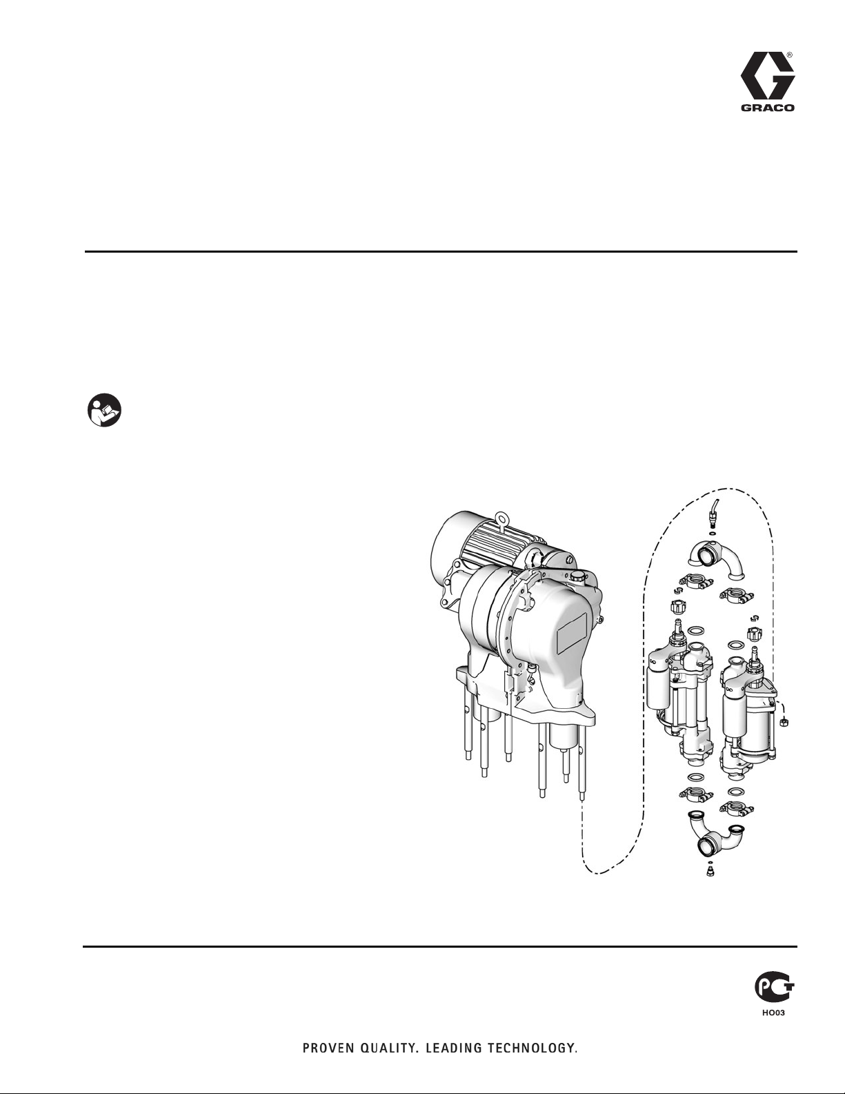
Instructions
Pump/Manifold Kits
To convert E-Flo® Electric Circulation Pumps to a different size lower.
For professional use only.
See page 2 for a list of available kits.
Important Safety Instructions
Read all warnings and instructions in this manual
and in E-Flo Repair-Parts manual 311594. Save
these instructions.
311611D
ENG
ti8720b
Page 2
Kit Parts
Kit Parts
Complete kits are available to convert from one size
lower to another. See the table below for available kits.
Kit Part
No.
289553 24F417
15J747 24F428
15J748 24F436
15J749 24F444
16F420 24F418
15J750 24F429
15J751 24F437
15J752 24F445
NOTE: The kits include the following parts. Parts
included in the kit are marked with an asterisk, for example (13*). Use all the new parts in the kit.
Ref.
No. Part No. Description Qty
13* 184128 COLLAR, coupling
14* 184059 NUT, coupling
15* 108683 NUT, lock, hex
16* 120351 GASKET, sanitary
17* n/a MANIFOLD
18* 120350 CLAMP, sanitary, 1.5
22* 24F428 LOWER, 1000 cc, Chromex cylinder;
24F436 LOWER, 1500 cc, Chromex cylinder;
24F444 LOWER, 2000 cc, Chromex cylinder;
24F429 LOWER, 1000 cc, MaxLife cylinder;
24F437 LOWER, 1500 cc, MaxLife cylinder;
Lower
Part No. Description
750 cc, Chromex
1000 cc, Chromex
1500 cc, Chromex
2000 cc, Chromex
750 cc, MaxLife
®
1000 cc, MaxLife
1500 cc, MaxLife
2000 cc, MaxLife
used in kit 15J747; see 3A0539 for
lower parts information
used in kit 15J748; see 3A0539 for
lower parts information
used in kit 15J749; see 3A0539 for
lower parts information
used in kit 15J750; see 3A0539 for
lower parts information
used in kit 15J751; see 3A0539 for
lower parts information
™
Ref.
No. Part No. Description Qty
24F445 LOWER, 2000 cc, MaxLife cylinder;
used in kit 15J752; see 3A0539 for
lower parts information
24F417 LOWER, 750 cc, Chromex cylinder;
used in kit 289553; see 3A0539 for
lower parts information
24F418 LOWER, 750 cc, MaxLife cylinder;
used in kit 16F420; see 3A0539 for
lower parts information
41* 111316 O-RING; chemically resistant fluoro-
elastomer
45* n/a PLUG, manifold
Parts designated n/a are not available separately.
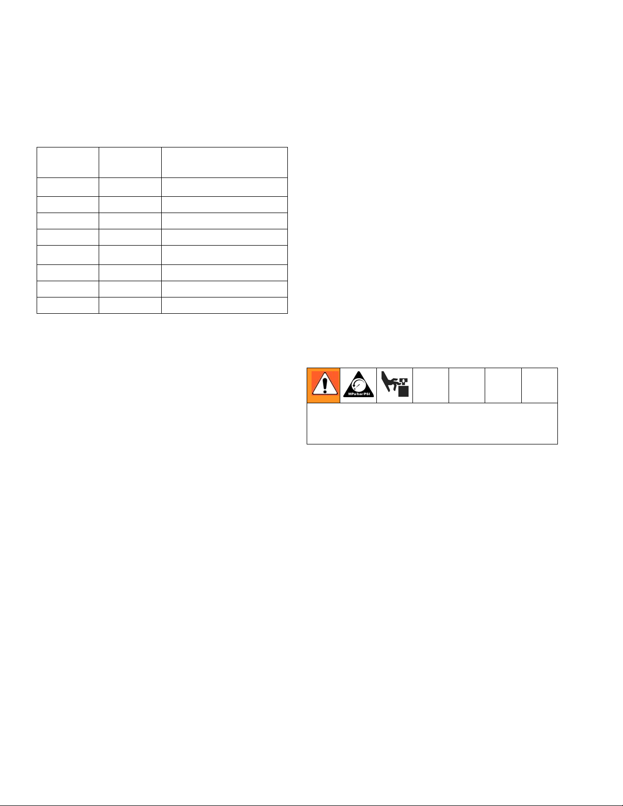
Pressure Relief Procedure
4
2
System pressure can cause the pump to cycle unex-
6
pectedly, which could result in serious injury from
4
splashing or moving parts.
2
4
1. Set START/STOP switch to STOP.
2
2. Push in SECURE DISABLE switch.
3. Open the back pressure regulator and all fluid drain
2
2
2
2
valves in the system, having a waste container
ready to catch drainage. Leave open until you are
ready to pressurize system again.
4. Check that pressure gauges on fluid supply and
return lines read zero. If gauges do not read zero,
determine cause and carefully relieve pressure by
VERY SLOWLY loosening a fitting. Clear obstruction before pressurizing system again.
2
2
2
2
2
2 311611D
Page 3

Flushing
Flushing
1. Follow Pressure Relief Procedure, page 2.
2. Supply the appropriate flushing material to the system.
3. Set pump to lowest possible fluid pressure, and start
the pump.
4. Flush long enough to thoroughly clean the system.
5. Follow Pressure Relief Procedure, page 2.
Kit Installation
Disassembly
10
Hold slider piston (9) flats with 3/4 in. wrench, and brace
against tie rod (3).
3
9
10
14
FIG. 1. Remove Coupling Nut (E-Flo Plus Shown)
8. Disconnect the fluid inlet and outlet lines from the
pump. Plug the ends to prevent fluid contamination.
12
ti9223b
32
1. Flush the pump, see page 3.
2. Jog the motor to bring the lower on the side being
repaired to the bottom of its stroke. This provides
access to the coupling nut (14).
3. Relieve the pressure, see page 2.
4. See F
5. Using a 1-5/8 in. open-end wrench, unscrew the
6. Repeat steps 2-5 for the other lower.
IG. 1. Place a 3/4 in. wrench on the slider pis-
ton (9) flats (just above the coupling nut), to keep
the slider piston/connecting rod from turning when
you are loosening the coupling nut (14). Orient the
wrench so it is braced against one of the tie rods (3).
Applying excessive force to the slider piston/connecting rod can shorten the life of the lower pin
bearing.
coupling nut (14) from the slider piston (9) and let it
slide down onto the pump piston rod. Be careful not
to lose the collars (13).
9. See F
10. Loosen the clamps (18) at the inlet and outlet mani-
11. Remove the coupling nut (14) and collars (13) from
12. Unscrew the locknuts (15). Remove the lower (22).
IG. 2. On pumps with a sensor circuit: At the
pump outlet manifold (17), loosen the transducer nut
(43) and unscrew the adapter (42) from the manifold. Remove the transducer (25a) from the manifold
port. Remove the existing o-ring (41) and discard.
folds (17). Remove the manifolds and gaskets (16).
the piston rods (PR).
See your separate lower manual for repair instructions.
7. Shut off electrical power and allow the unit to cool.
311611D 3
Page 4

Kit Installation
Reassembly
1. See FIG. 2. Install the coupling nut (14) on the
lower’s piston rod (PR).
2. Orient the lower (22) to the gear reducer (GR) as
shown. Position the lower on the tie rods (3). Screw
the tie rod locknuts (15) onto the tie rods handtight.
3. Assemble the inlet and outlet manifolds (17) to the
lower, using new gaskets (16) and clamps (18).
Torque the clamps (18) to 15-20 ft-lb (21-27 N•m).
4. Torque the locknuts (15) to 50-60 ft-lb (68-80 N•m).
5. At the outlet manifold (17):
a. On pumps with a sensor circuit: Install a new
black o-ring (41) on the transducer (25a). Insert
the transducer into the outlet manifold (17).
Torque the adapter (42) first, then the nut (43) to
15-20 ft-lb (21-27 N•m).
b. On pumps without a sensor circuit: Install a
black o-ring (41) on the plug (45). Screw the
plug into the outlet manifold (17) and torque to
15-20 ft-lb (21-27 N•m).
6. Install a black o-ring (41) on the plug (45). Screw the
plug into the inlet manifold (17) and torque to 15-20
ft-lb (21-27 N•m).
7. Ensure that the collars (13) are in place in the coupling nut (14).
8. Place a 3/4 in. wrench on the flats of the slider piston (9), to keep it from turning when you are tightening the coupling nut (14). Orient the wrench so it is
braced against one of the tie rods (3) or pump
stand. Tighten the coupling nut (14) onto the slider
piston (9) and torque to 75-80 ft-lb (102-108 N•m).
9. Turn on power and jog the motor to bring the other
drive to the bottom of its stroke. Repeat procedure
to connect the other lower.
NOTE: Update the drive software to reflect the change
in size of the lowers. See manual 311596.
10. Flush and test the pump before reinstalling it in the
system. Connect hoses and flush the pump. While it
is pressurized, check for smooth operation and
leaks. Adjust or repair as necessary before reinstalling in the system.
4 311611D
Page 5

4
Torque to 50-60 ft-lb (68-80 N•m).
5
Torque to 75-80 ft-lb (102-108 N•m).
7
Torque to 15-20 ft-lb (21-27 N•m).
14
Apply lithium grease.
15
On pumps without a sensor circuit, install a
plug (45) instead of the transducer (25a),
Kit Installation
25a
43
7
42
7
1
15
41*
17*
18*
7
13*
16*
14*
5
14
PR
*22
15*
*16
4
22*
9
3
FIG. 2: Fluid Section
41*
45*
16*
18*
7
17*
7
ti8720b
311611D 5
Page 6

Graco Standard Warranty
Graco warrants all equipment referenced in this document which is manufactured by Graco and bearing its name to be free from defects in
material and workmanship on the date of sale to the original purchaser for use. With the exception of any special, extended, or limited warranty
published by Graco, Graco will, for a period of twelve months from the date of sale, repair or replace any part of the equipment determined by
Graco to be defective. This warranty applies only when the equipment is installed, operated and maintained in accordance with Graco’s written
recommendations.
This warranty does not cover, and Graco shall not be liable for general wear and tear, or any malfunction, damage or wear caused by faulty
installation, misapplication, abrasion, corrosion, inadequate or improper maintenance, negligence, accident, tampering, or substitution of
non-Graco component parts. Nor shall Graco be liable for malfunction, damage or wear caused by the incompatibility of Graco equipment with
structures, accessories, equipment or materials not supplied by Graco, or the improper design, manufacture, installation, operation or
maintenance of structures, accessories, equipment or materials not supplied by Graco.
This warranty is conditioned upon the prepaid return of the equipment claimed to be defective to an authorized Graco distributor for verification of
the claimed defect. If the claimed defect is verified, Graco will repair or replace free of charge any defective parts. The equipment will be returned
to the original purchaser transportation prepaid. If inspection of the equipment does not disclose any defect in material or workmanship, repairs will
be made at a reasonable charge, which charges may include the costs of parts, labor, and transportation.
THIS WARRANTY IS EXCLUSIVE, AND IS IN LIEU OF ANY OTHER WARRANTIES, EXPRESS OR IMPLIED, INCLUDING BUT NOT LIMITED
TO WARRANTY OF MERCHANTABILITY OR WARRANTY OF FITNESS FOR A PARTICULAR PURPOSE.
Graco’s sole obligation and buyer’s sole remedy for any breach of warranty shall be as set forth above. The buyer agrees that no other remedy
(including, but not limited to, incidental or consequential damages for lost profits, lost sales, injury to person or property, or any other incidental or
consequential loss) shall be available. Any action for breach of warranty must be brought within two (2) years of the date of sale.
GRACO MAKES NO WARRANTY, AND DISCLAIMS ALL IMPLIED WARRANTIES OF MERCHANTABILITY AND FITNESS FOR A
PARTICULAR PURPOSE, IN CONNECTION WITH ACCESSORIES, EQUIPMENT, MATERIALS OR COMPONENTS SOLD BUT NOT
MANUFACTURED BY GRACO. These items sold, but not manufactured by Graco (such as electric motors, switches, hose, etc.), are subject to
the warranty, if any, of their manufacturer. Graco will provide purchaser with reasonable assistance in making any claim for breach of these
warranties.
In no event will Graco be liable for indirect, incidental, special or consequential damages resulting from Graco supplying equipment hereunder, or
the furnishing, performance, or use of any products or other goods sold hereto, whether due to a breach of contract, breach of warranty, the
negligence of Graco, or otherwise.
FOR GRACO CANADA CUSTOMERS
The Parties acknowledge that they have required that the present document, as well as all documents, notices and legal proceedings entered into,
given or instituted pursuant hereto or relating directly or indirectly hereto, be drawn up in English. Les parties reconnaissent avoir convenu que la
rédaction du présente document sera en Anglais, ainsi que tous documents, avis et procédures judiciaires exécutés, donnés ou intentés, à la suite
de ou en rapport, directement ou indirectement, avec les procédures concernées.
Graco Information
For the latest information about Graco products, visit www.graco.com.
TO PLACE AN ORDER, contact your Graco distributor or call to identify the nearest distributor.
Phone: 612-623-6921 or Toll Free: 1-800-328-0211 Fax: 612-378-3505
All written and visual data contained in this document reflects the latest product information available at the time of publication.
Graco reserves the right to make changes at any time without notice.
Original instructions. This manual contains English. MM 311611
Graco Headquarters: Minneapolis
International Offices: Belgium, China, Japan, Korea
GRACO INC. P.O. BOX 1441 MINNEAPOLIS, MN 55440-1441
Copyright 2007, Graco Inc. is registered to ISO 9001
www.graco.com
Revised 08/2010
 Loading...