

Page 1
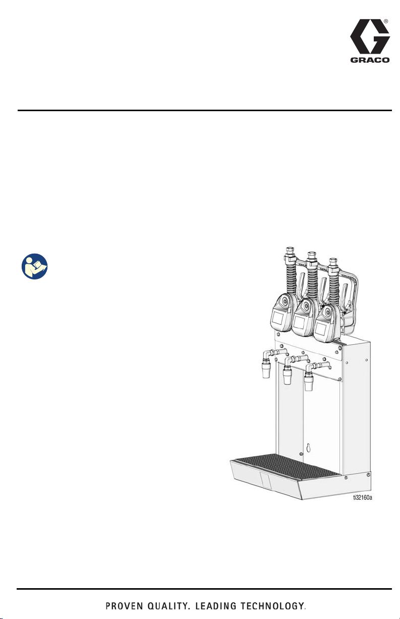
Installation and Service
Pulse® Metered Dispense
Valve Oil Bar
For fixed mounting of up to three Pulse metered dispense valves.
Not approved for use in explosive atmospheres or hazardous locations. For professional
use only.
Model No.: 25D130 - Configures metered dispense valves for installation in the
oil bar.
NOTE: One Model 25D130 is required for each model 24N415 metered dispense valve.
Maximum Working Pressure: 1500 psi (103 bar,10 MPa)
Model No.: 25D121 - Oil Dispenser Bar
3A5573C
EN
Important Safety
Instructions
Read all warnings and instructions
in this manual and all related Pulse
system manuals. Save all
instructions.
Related Manuals
3A5412 - Pulse Metered Dispense Valve
Refer to Parts, page 8 for reference numbers
used in these instructions.
Page 2
Installation
3
9
1
7
Installation
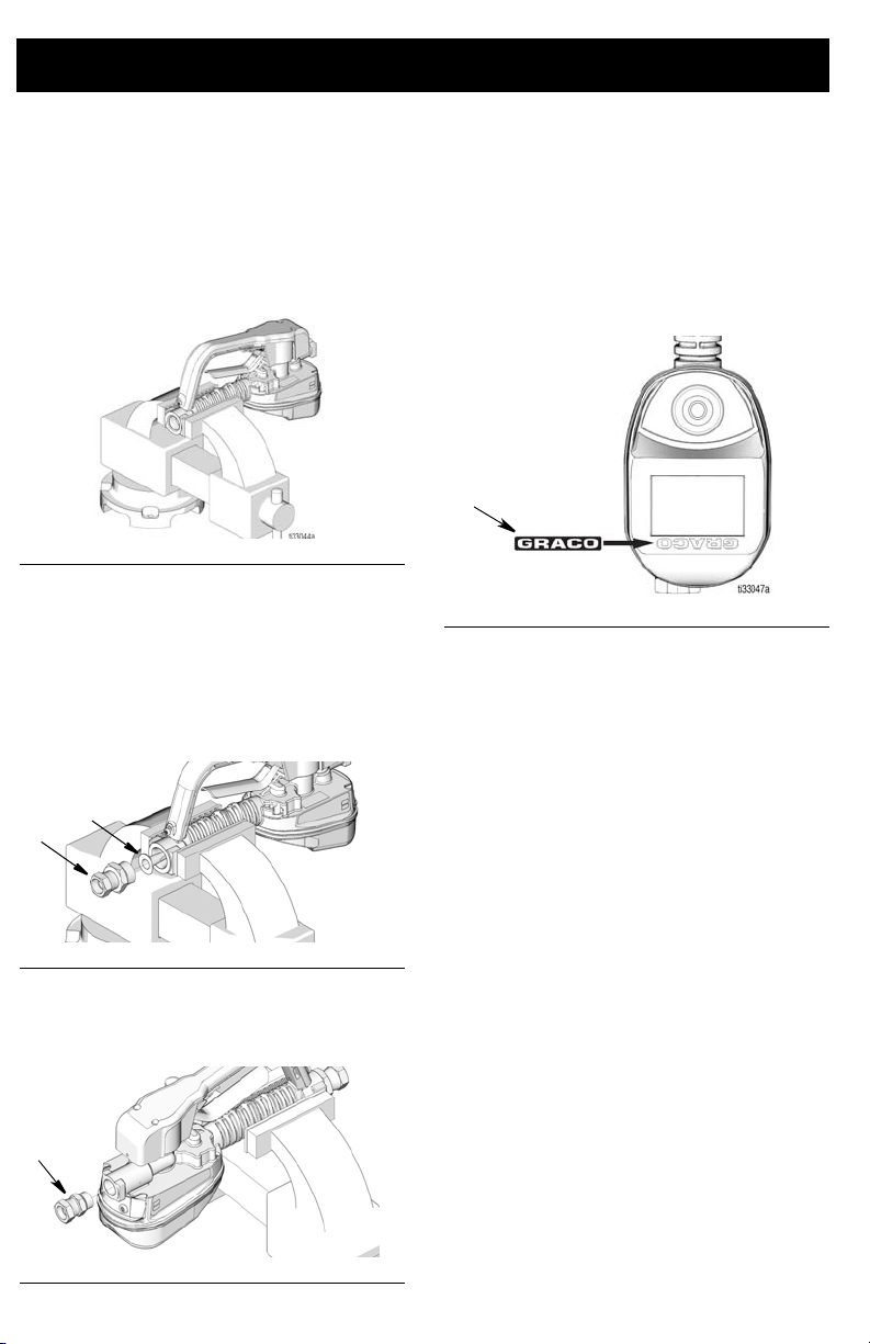
Prepare the Metered Dispense Valve for Installation
1. Secure the metered dispense valve in a
vise (FIG. 1).
FIG. 1
2. Install strainer (9) and fitting (3) in the
IG. 2). Use wrench to tighten fit-
inlet (F
ting.
NOTE: An o-ring is not required for the
strainer (9) installation. An o-ring is
required and installed on fitting (3).
4. Install Graco identification label (7) over
the existing GRACO identification label
in the orientation shown in F
IG. 4.
FIG. 4
5. Use the Utility Menu to flip the display for
easy viewing when the metered
dispense valve is installed in the Oil Bar.
See the Pulse Metered Dispense Valve
instruction manual for this procedure.
FIG. 2
3. Install fitting (1) in the outlet as shown
in FIG. 3. Tighten fitting with a wrench.
FIG. 3
2 3A5573C
Page 3
Assemble the Oil Bar
27
22
28
29
21
24
21
28, 29
27
25
27
24
Installation
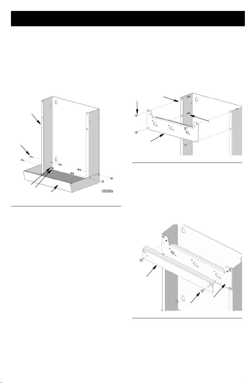
The oil bar requires assembly prior to use.
1. Attach dispenser wrapper (21) to drain
pan (22) using screws (27), lock
washers(28) and nuts (29) and existing
holes. Tighten nuts securely. (See FIG.
5).
FIG. 5
2. Use the existing mounting holes in the
back of the oil bar to secure it to a wall.
Select a location that is easily accessible
to the user and will adequately support
the weight of the oil bar, metered
dispense valves and plumbing.
3. Attach the meter mounting plate (24) to
the wrapper dispenser (21) using screws
(27), lock washers(28) and nuts (29) and
existing holes. Tighten nuts securely.
Refer to F
orientation for these parts.
IG. 6 for the correct installation
FIG. 6
4. Connect cover panel plate (25) to meter
mounting plate (24) using screws (27)
and existing holes. Tighten screws
securely. Refer to F
installation orientation for these parts.
NOTE: Do not assemble cover panel
plate (25) prior to meter installation.
IG. 7 for the correct
NOTE: Fasteners for this installation are
not included in the kit and must be
provided by the user. When selecting
fasteners consider the weight of the oil
bar, metered dispense valves, plumbing
fixtures and dispensed oil in the
container placed on the shelf. See
Technical Specifications, page 10.
FIG. 7
3A5573C 3
5. Install pan strainer (23) in drain pan (22).
Page 4
Installation
8
2
Sealant
or PTFE
Tape
25
27
24
2
a
b
24
4
5
24
2
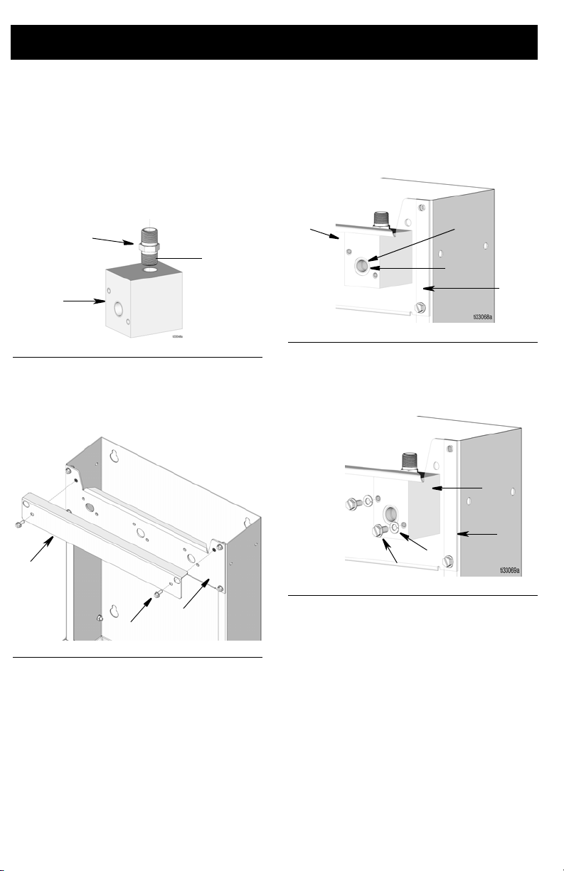
Install the Metered Dispense Valve in the Oil Bar
1. Wrap threads of pipe nipple (8) with
PTFE tape or thread sealant as shown in
FIG. 8. Install pipe nipple (8) in opening of
manifold (2). Tighten securely. Refer to
IG. 8 to determine the correct
F
installation position.
FIG. 8
2. If installed when assembling the Oil
Bar, remove screws (27) and remove
access panel (25).
3. Position manifold (2) inside oil bar,
orienting opening (a) on the front of the
manifold with opening (b) in the
mounting plate (24) as shown in F
IG. 10.
FIG. 10
4. Install screws (5) and washers (4) to hold
the manifold (2) in place. Tighten
securely.
FIG. 11
FIG. 9
4 3A5573C
Page 5

Installation
1
8
2
10
b
24
2
10
6
11
3
c
5. Install the metered dispense valve in oil
bar housing by connecting fitting (1) on
metered dispense valve to pipe nipple
(8) in manifold (2) as shown in FIG. 12.
Tighten securely.
NOTE: Do NOT apply thread sealant or
PTFE tape to threads of fitting (1).
FIG. 12
6. Wrap threads on the long end of nipple
adapter (10) with PTFE tape or thread
sealant as shown in F
IG. 13.
7. Install the end of the nipple adapter (10)
that was wrapped in the PTFE tape or
treated with thread sealant into the
manifold (2) through the hole (b) in the oil
bar mounting plate (24).
FIG. 14
8. Connect the swivel elbow (6) and high
flow nozzle (11) to nipple adapter (10) in
the orientation shown in F
securely.
NOTE: Do NOT apply thread sealant or
PTFE tape to threads.
IG. 15. Tighten
FIG. 13
FIG. 15
9. Connect fluid distribution lines (c) to
fitting (3).
3A5573C 5
FIG. 16
Page 6

Repair and Maintenance
WARNING
3
c
Repair and Maintenance
Pressure Relief Procedure
PRESSURIZED FLUID HAZARD
This equipment stays pressurized until
pressure is manually relieved. To help prevent serious injury from pressurized fluid,
such as skin injection, splashing fluid and
moving parts, follow the Pressure Relief
Procedure when you stop dispensing and
before cleaning, checking, or servicing the
equipment.
PERSONAL PROTECTIVE EQUIPMENT
Wear appropriate protective equipment
when in the work area to help prevent
serious injury, including eye injury, hearing
loss, inhalation of toxic fumes, and burns.
1. Turn off power supply to the pump.
2. Place a container under the drain valve
on the oil bar (F
3. Pull trigger to dispense as much of the
fluid as possible to relieve pressure.
4. Leave the nozzle open until you are
ready to pressurize the system.
IG. 18). Open the nozzle.
Oil Bar Disassembly
1. Relieve pressure. See the Pressure
Relief Procedure.
2. Disconnect fluid distribution lines (c)
from fitting (3) (see F
FIG. 17
3. Pull trigger to dispense as much of the
fluid remaining in the line as possible
(F
IG. 18).
NOTE: A collection container should
already be in place and the nozzle
should be open after performing
Pressure Relief Procedure (Step 1).
IG. 17).
FIG. 18
6 3A5573C
Page 7

4. Remove screws (27) and access panel
25
27
24
1
8
2
10
6
11
5
4
1
(25) (see FIG. 19).
FIG. 19
5. Disconnect fitting (1) from pipe nipple (8)
in manifold (2) as shown in FIG. 20.
Repair and Maintenance
FIG. 21
7. Remove screws (5) and washers (4)
from manifold (2). Lift manifold (2)
straight up and out of the oil bar housing
(FIG. 22).
FIG. 22
8. To protect the metered dispense valve,
lay it face down on a padded surface
FIG. 20
6. Unscrew nipple adapter assembly (10, 6
and 11) from manifold (1).
while performing any maintenance or
service work on the metered dispense
valve or oil bar.
Oil Bar Reassembly
NOTE: The nipple adapter (10), elbow
(6) and swivel nozzle (11) do not have to
be disassembled. These pieces can be
removed form the manifold as a single
assembly (F
3A5573C 7
IG. 21).
To reassemble the oil bar, follow the
Installing Metered Dispense Valve in Oil
Bar instructions beginning on page 4.
Page 8

Parts
3
9
1
8
4
5
6
11
10
2
Parts
Model 25D130
Ref Part No. Description Qty
1 131244 FITTING,
2 131245 MANIFOLD,
3 131246 FITTING,
4 100016 WASHER, lock 2
5 108296 SCREW, hex 2
6 121079 SWIVEL, elbow,
7 130195 LABEL, brand, oil bar 1
8 156849 PIPE, nipple 1
9 15M308 STRAINER, wire
10 160790 FITTING, nipple,
11 255461 NOZZLE, high flow 1
3/4 ORB UNF X 3/8
NPSM
dispenser
1-1/16 ORB UNF X
1/2 NPSM
ORB X NPSM
mesh
adapter
1
1
1
1
1
1
Metered Dispense Valve 24N415 is shown for
reference only. It must be ordered separately.
8 3A5573C
Page 9

Model 25D121
21
23
26
22
25
24
28
27
30
29
29
Parts
Ref Part No. Description Qty
21 181316 WRAPPER,
22 16D537 PAN, drain, coating 1
23 181319 STRAINER, pan 1
24 131242 PLATE, mount 1
25 131243 PLATE, cover panel 1
26 104663 PLUG, pipe 1
dispenser
Ref Part No. Description Qty
1
27* 108296 SCREW, hex 18
28* 100016 WASHER, lock 16
29* 100015 NUT, hex 16
30* 159346 WASHER 6
* Extra parts included for connecting multiple oil
bars together.
3A5573C 9
Page 10

Technical Specifications
Technical Specifications
Oil Bar
US Metric
Maximum Working Pressure 1500 psi 103 bar, 10 MPa
Wetted Materials Carbon steel, aluminum, Buna-n rubber
Weight
Model 25D121 30 lbs 13.61 kg
Model 25D130 5 lbs 2.26 kg
10 3A5573C
Page 11

NOTES
NOTES
3A5573C 11
Page 12

Graco Standard Warranty
Graco warrants all equipment referenced in this document which is manufactured by Graco and bearing its name to be
free from defects in material and workmanship on the date of sale to the original purchaser for use. With the exception of
any special, extended, or limited warranty published by Graco, Graco will, for a period of twelve months from the date of
sale, repair or replace any part of the equipment determined by Graco to be defective. This warranty applies only when
the equipment is installed, operated and maintained in accordance with Graco’s written recommendations.
This warranty does not cover, and Graco shall not be liable for general wear and tear, or any malfunction, damage or
wear caused by faulty installation, misapplication, abrasion, corrosion, inadequate or improper maintenance, negligence,
accident, tampering, or substitution of non-Graco component parts. Nor shall Graco be liable for malfunction, damage or
wear caused by the incompatibility of Graco equipment with structures, accessories, equipment or materials not supplied
by Graco, or the improper design, manufacture, installation, operation or maintenance of structures, accessories,
equipment or materials not supplied by Graco.
This warranty is conditioned upon the prepaid return of the equipment claimed to be defective to an authorized Graco
distributor for verification of the claimed defect. If the claimed defect is verified, Graco will repair or replace free of charge
any defective parts. The equipment will be returned to the original purchaser transportation prepaid. If inspection of the
equipment does not disclose any defect in material or workmanship, repairs will be made at a reasonable charge, which
charges may include the costs of parts, labor, and transportation.
THIS WARRANTY IS EXCLUSIVE, AND IS IN LIEU OF ANY OTHER WARRANTIES, EXPRESS OR IMPLIED,
INCLUDING BUT NOT LIMITED TO WARRANTY OF MERCHANTABILITY OR WARRANTY OF FITNESS FOR A
PARTICULAR PURPOSE.
Graco’s sole obligation and buyer’s sole remedy for any breach of warranty shall be as set forth above. The buyer agrees
that no other remedy (including, but not limited to, incidental or consequential damages for lost profits, lost sales, injury to
person or property, or any other incidental or consequential loss) shall be available. Any action for breach of warranty
must be brought within two (2) years of the date of sale.
GRACO MAKES NO WARRANTY, AND DISCLAIMS ALL IMPLIED WARRANTIES OF MERCHANTABILITY AND
FITNESS FOR A PARTICULAR PURPOSE, IN CONNECTION WITH ACCESSORIES, EQUIPMENT, MATERIALS OR
COMPONENTS SOLD BUT NOT MANUFACTURED BY GRACO. These items sold, but not manufactured by Graco
(such as electric motors, switches, hose, etc.), are subject to the warranty, if any, of their manufacturer. Graco will provide
purchaser with reasonable assistance in making any claim for breach of these warranties.
In no event will Graco be liable for indirect, incidental, special or consequential damages resulting from Graco supplying
equipment hereunder, or the furnishing, performance, or use of any products or other goods sold hereto, whether due to
a breach of contract, breach of warranty, the negligence of Graco, or otherwise.
FOR GRACO CANADA CUSTOMERS
The Parties acknowledge that they have required that the present document, as well as all documents, notices and legal
proceedings entered into, given or instituted pursuant hereto or relating directly or indirectly hereto, be drawn up in
English. Les parties reconnaissent avoir convenu que la rédaction du présente document sera en Anglais, ainsi que tous
documents, avis et procédures judiciaires exécutés, donnés ou intentés, à la suite de ou en rapport, directement ou
indirectement, avec les procédures concernées.
Graco Information
For the latest information about Graco products, visit www.graco.com.
For patent information, see www.graco.com/patents.
TO PLACE AN ORDER, contact your Graco distributor or call to identify the nearest distributor.
Phone: 612-623-6928 or Toll Free: 1-800-533-9655, Fax: 612-378-3590
All written and visual data contained in this document reflects the latest product information available at
Graco reserves the right to make changes at any time without notice.
Original instructions. This manual contains English. MM 3A5573
International Offices: Belgium, China, Japan, Korea
GRACO INC. AND SUBSIDIARIES • P.O. BOX 1441 • MINNEAPOLIS MN 55440-1441 • USA
Copyright 2018, Graco Inc. All Graco manufacturing locations are registered to ISO 9001.
the time of publication.
Graco Headquarters: Minneapolis
www.graco.com
Revision, September 2019
 Loading...