

Graco Pro Xp H60T10, Pro Xp H85T10, Pro Xp H85M10, Pro Xp H60M10, Pro Xp H85M57 Instructions Manual
...Page 1
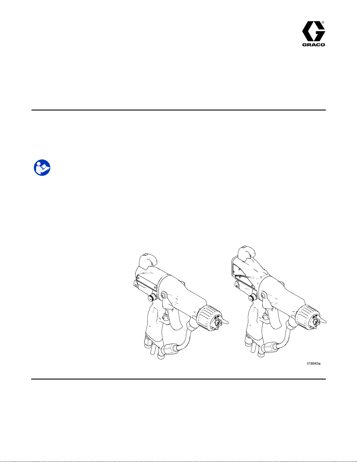
Instructions-Parts
Pro
Pro Pro
Air
Air Air
For
For For
For
For For
use
use use
3000psi(21MPa,210bar)Maximum
FluidWorkingPressure
100psi(0.7MPa,7bar)MaximumAir
WorkingPressure
Seepage3formodelpartnumbersand
approvalinformation.
Xp™
Xp™ Xp™
Assisted
- --Assisted Assisted
use
use use
use
use use
only.
only. only.
Class
in ininClass Class
Group
in ininGroup Group
Important
Important Important
Thisequipmentcouldpresenthazardsifnotoperatedaccordingto
theinformationinthismanual.Read Read
this
manual
this this
manual manual
Electrostatic
Electrostatic Electrostatic
Spray
Spray Spray
Div.
I, I,I,Div. Div.
II,
II, II,
Safety
Safety Safety
before
before before
Hazardous
I IIHazardous Hazardous
Zone
Zone Zone
Explosive
1 11Explosive Explosive
Instructions
Instructions Instructions
using
using using
Gun
Gun Gun
Locations
Locations Locations
Atmosphere
Atmosphere Atmosphere
Read
the
equipment.
the the
equipment. equipment.
using
Group
using using
Group Group
Locations
Locations Locations
all
warnings
all all
warnings warnings
Save
Save Save
and
and and
these
instructions.
these these
instructions. instructions.
materials.
D DDmaterials. materials.
using
Group
using using
Group Group
instructions
instructions instructions
IIA
materials.
IIA IIA
materials. materials.
in
in in
3A2495K
EN
For
professional
For For
professional professional
PROVENQUALITY.LEADINGTECHNOLOGY.
Page 2

Contents
Contents Contents
Models...............................................................3
Approvals...........................................................3
RelatedManuals................................................3
Warnings...........................................................4
GunOverview....................................................7
HowtheElectrostaticAASprayGun
Works............................................7
Controls,Indicators,andComponents...........8
SmartGuns.................................................9
Installation..........................................................14
WarningSign...............................................14
VentilatetheSprayBooth.............................14
AirSupplyLine............................................15
FluidSupplyLine.........................................15
Grounding...................................................17
GunSetup..........................................................21
GunSetupProcedure...................................21
CheckGunElectricalGrounding...................24
CheckFluidResistivity.................................25
CheckFluidViscosity...................................25
FlushBeforeUsingEquipment......................25
Operation...........................................................26
PressureReliefProcedure............................26
Startup........................................................27
Shutdown....................................................27
Maintenance......................................................28
DailyCareandCleaningChecklist................28
Flushing......................................................28
CleantheGunDaily.....................................30
DailySystemCare.......................................31
ElectricalTests...................................................32
TestGunResistance....................................32
TestPowerSupplyResistance.....................33
TestGunBarrelResistance..........................34
Troubleshooting..................................................35
SprayPatternTroubleshooting......................35
GunOperationTroubleshooting....................36
ElectricalTroubleshooting............................37
Repair................................................................39
PreparetheGunforService.........................39
AirCap,SprayTip,andFluidSeatHousing
Replacement..................................40
ElectrodeReplacement................................41
FluidTubeRemovalandReplacement...........42
FluidFilterReplacement...............................42
GunBarrelRemoval.....................................43
GunBarrelInstallation..................................43
FluidNeedleReplacement............................44
PowerSupplyRemovaland
Replacement..................................45
AlternatorRemovalandReplacement...........46
FanAirAdjustmentValveRepair..................48
AtomizingAirAdjustmentValve
Repair............................................48
ESOn-OffValveRepair...............................49
AirValveRepair...........................................50
SmartModuleReplacement..........................51
AirSwivelandExhaustValve
Replacement..................................52
Parts..................................................................53
StandardAir-AssistedSprayGun
Assembly.......................................53
SmartAir-AssistedSprayGun
Assembly.......................................55
AlternatorAssembly.....................................57
ESOn-OffValveAssembly...........................58
FanAirAdjustmentValveAssembly..............59
AirCapAssembly........................................60
SmartModuleAssembly...............................60
SprayTipSelectionChart....................................61
AEMFineFinishSprayTips..........................61
AEFFineFinishPre-OriceSpray
Tips...............................................62
RoundSprayTips........................................63
RecommendedFilterSizes...........................64
RepairKitsandAccessories................................65
GunAccessories..........................................65
InlineFluidFilterKitAccessories...................65
OperatorAccessories...................................66
SystemAccessories.....................................66
Signs..........................................................66
TestEquipment...........................................66
Hoses.........................................................67
Dimensions........................................................68
TechnicalSpecications......................................69
GracoProXpWarranty.......................................70
2
3A2495K
Page 3
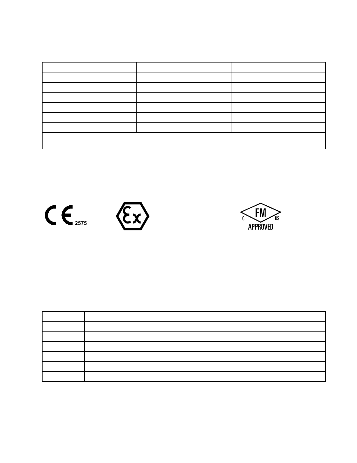
Models
2575
Models
Models Models
Part
No.
Part Part
No. No.
kV
kV kV
Display
Display Display
H60T1060
H60M1060
H85T1085
H85M1085
H85T57*
H85M57*
*HighAirFlowGunModels,equippedwithESOn-OffwithAirRestrictorValve,whichlimitsairowtothe
turbine.Forapplicationsthatrequirehighairowattheaircap.
Approvals
Approvals Approvals
85
85
G
II IIII2 22G G
0.24mJT6
Standard
Smart
Standard
Smart
Standard
Smart
FM12ATEX0068
EN50050–1
Ta0°C–50°C
Related
Related Related
Manual
Manual Manual
3A2499
307263ProbeandMeter,Instructions
308393
309227
309455TestFixture,HighVoltageProbe,andkVMeter,Instructions
406999
No.
No. No.
Manuals
Manuals Manuals
Description
Description Description
RoundSprayKit,Instructions
GunWasherKit,Instructions
GunFlushBoxModule,Instructions
VoltageTesterConversionKit,Instructions
3A2495K3
Page 4
Warnings
Warnings
Warnings Warnings
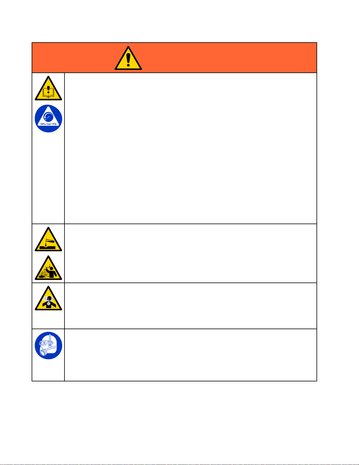
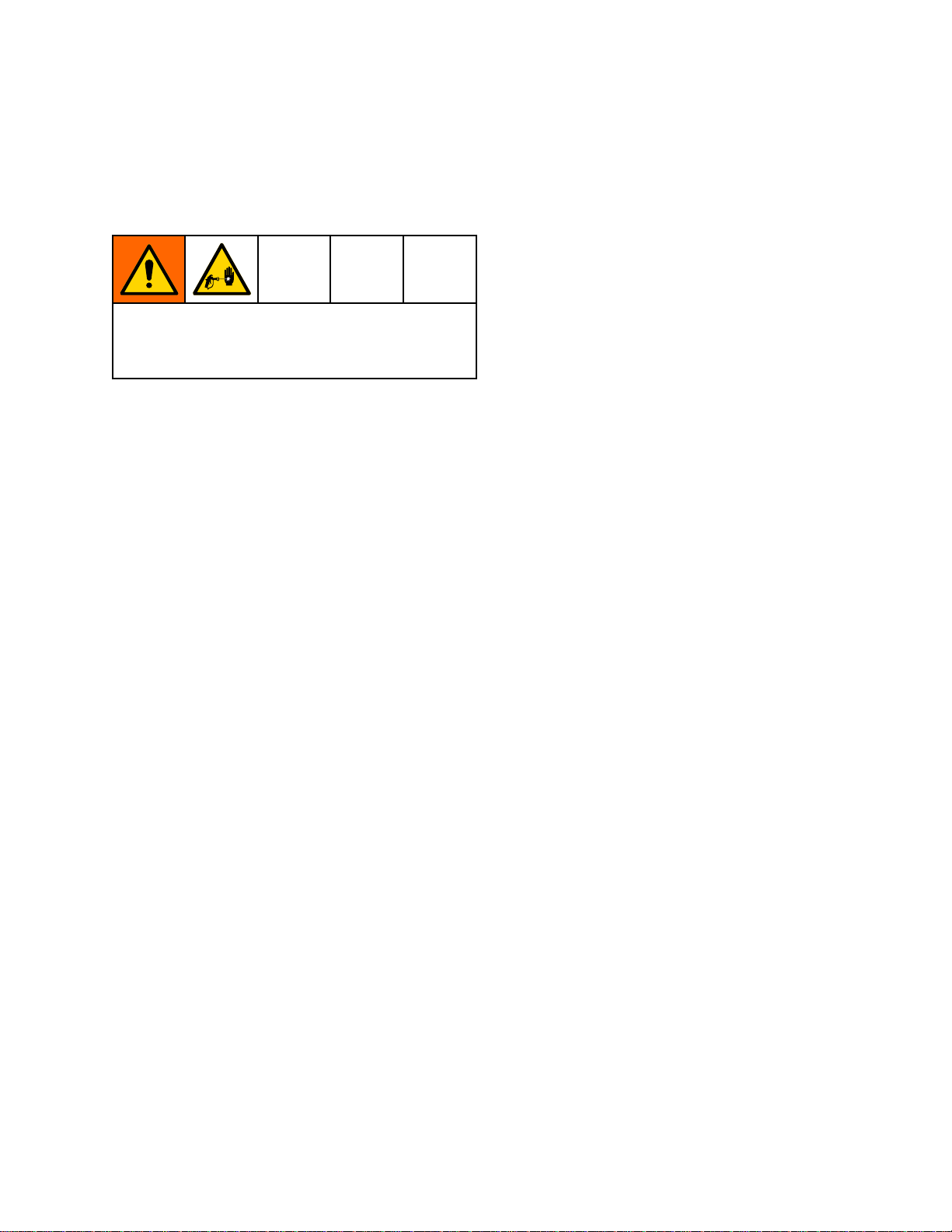
Thefollowingwarningsareforthesetup,use,grounding,maintenance,andrepairofthisequipment.The
exclamationpointsymbolalertsyoutoageneralwarningandthehazardsymbolsrefertoprocedure-specic
risks.Whenthesesymbolsappearinthebodyofthismanual,referbacktotheseWarnings.Product-specic
hazardsymbolsandwarningsnotcoveredinthissectionmayappearthroughoutthebodyofthismanual
whereapplicable.
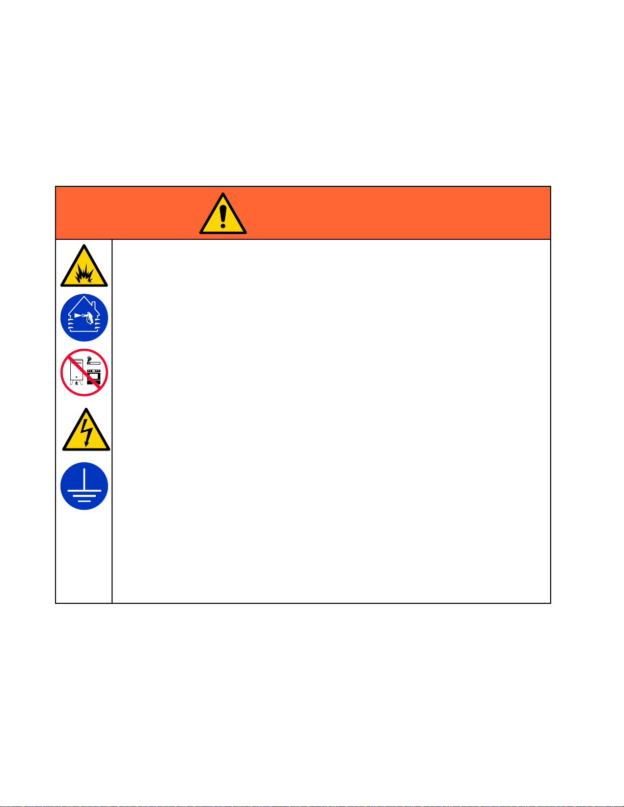
WARNING
WARNING WARNING
FIRE,
EXPLOSION,
FIRE, FIRE,
EXPLOSION, EXPLOSION,
Flammablefumes,suchassolventandpaintfumes,inwork work
Paintorsolventowingthroughtheequipmentcancausestaticsparking.Tohelpprevent
re,explosion,andelectricshock:
•Electrostaticequipmentmustbeusedonlybytrained,qualiedpersonnelwhounderstand
therequirementsofthismanual.
•Groundallequipment,personnel,objectbeingsprayed,andconductiveobjectsinorcloseto
sprayarea.Resistancemustnotexceed1megohm.SeeGrounding Grounding
•OnlyusegroundedGracoconductiveairsupplyhoses.
•Donotusepaillinersunlesstheyareconductiveandgrounded.
Stop
•Stop Stop
•Checkgunresistance,hoseresistance,andelectricalgroundingdaily.
•Useandcleanequipmentonlyinwellventilatedarea.
•Interlockthegunairanduidsupplytopreventoperationunlessventilationairowisabove
•UseonlyGroupIIAorGroupDmaterials.
•Usecleaningsolventswithhighestpossibleashpointwhenushingorcleaningequipment.
•Neversprayorushsolventathighpressure.
•Tocleantheexterioroftheequipment,cleaningsolventsmusthaveaashpointatleast15°
•Alwaysturntheelectrostaticsoffwhenushing,cleaningorservicingequipment.
•Eliminateallignitionsources;suchaspilotlights,cigarettes,portableelectriclamps,and
•Donotplugorunplugpowercordsorturnlightsonoroffwhenammablefumesarepresent.
•Keepworkareafreeofdebris,includingsolvent,ragsandgasoline.
•Keepthesprayareacleanatalltimes.Usenon-sparkingtoolstocleanresiduefromthe
•Keepaworkingreextinguisherintheworkarea.
operation
operation operation
equipmentuntilyouidentifyandcorrecttheproblem.
theminimumrequiredvalue.
Cor59°Faboveambienttemperature.Non-ignitableuidsarepreferred.
plasticdropcloths(potentialstaticsparking).
boothandhangers.
AND
ELECTRIC
AND AND
ELECTRIC ELECTRIC
immediately
immediately immediately
ifstaticsparkingoccursoryoufeelashock.Donotuse
SHOCK
SHOCK SHOCK
HAZARD
HAZARD HAZARD
work
area
area area
canigniteorexplodee.
Grounding
instructions.
4
3A2495K
Page 5
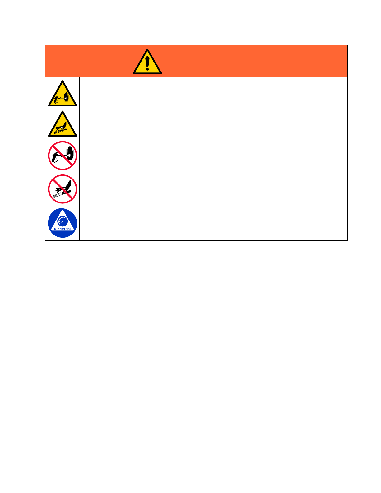
WARNING
WARNING WARNING
SKIN
INJECTION
SKIN SKIN
INJECTION INJECTION
High-pressureuidfromgun,hoseleaks,orrupturedcomponentswillpierceskin.Thismay
looklikejustacut,butitisaseriousinjurythatcanresultinamputation.Get Get
treatment.
treatment. treatment.
•Donotspraywithouttipguardandtriggerguardinstalled.
•Engagetriggerlockwhennotspraying.
•Donotpointgunatanyoneoratanypartofthebody.
•Donotputyourhandoverthespraytip.
•Donotstopordeectleakswithyourhand,body,glove,orrag.
•FollowthePressure Pressure
orservicingequipment.
•Tightenalluidconnectionsbeforeoperatingtheequipment.
•Checkhosesandcouplingsdaily.Replacewornordamagedpartsimmediately.
HAZARD
HAZARD HAZARD
Get
immediate
immediate immediate
Pressure
Relief
Procedure
Relief Relief
Procedure Procedure
whenyoustopsprayingandbeforecleaning,checking,
Warnings
surgical
surgical surgical
3A2495K5
Page 6
Warnings
WARNING
WARNING WARNING
EQUIPMENT
EQUIPMENT EQUIPMENT
Misusecancausedeathorseriousinjury.
•Donotoperatetheunitwhenfatiguedorundertheinuenceofdrugsoralcohol.
•Donotexceedthemaximumworkingpressureortemperatureratingofthelowestrated
systemcomponent.SeeTechnical Technical
•Useuidsandsolventsthatarecompatiblewithequipmentwettedparts.SeeTechnical Technical
Specications
Specications Specications
Forcompleteinformationaboutyourmaterial,requestSafetyDataSheets(SDSs)from
yourdistributororretailer.
•Donotleavetheworkareawhileequipmentisenergizedorunderpressure.
•TurnoffallequipmentandfollowthePressure Pressure
•Checkequipmentdaily.Repairorreplacewornordamagedpartsimmediatelywithgenuine
manufacturer’sreplacementpartsonly.
•Donotalterormodifyequipment.Alterationsormodicationsmayvoidagencyapprovals
andcreatesafetyhazards.
•Makesureallequipmentisratedandapprovedfortheenvironmentinwhichyouareusingit.
•Useequipmentonlyforitsintendedpurpose.Callyourdistributorforinformation.
•Routehosesandcablesawayfromtrafcareas,sharpedges,movingparts,andhotsurfaces.
•Donotkinkoroverbendhosesorusehosestopullequipment.
•Keepchildrenandanimalsawayfromworkarea.
•Complywithallapplicablesafetyregulations.
PLASTIC
PLASTIC PLASTIC
Manycleaningsolventscandegradeplasticpartsandcausethemtofail,whichcouldcause
seriousinjuryorpropertydamage.
MISUSE
MISUSE MISUSE
PARTS
PARTS PARTS
HAZARD
HAZARD HAZARD
Technical
inallequipmentmanuals.Readuidandsolventmanufacturer’swarnings.
CLEANING
CLEANING CLEANING
SOLVENT
SOLVENT SOLVENT
Specications
Specications Specications
Pressure
HAZARD
HAZARD HAZARD
Relief
Relief Relief
inallequipmentmanuals.
Procedure
Procedure Procedure
whenequipmentisnotinuse.
Technical
•Useonlycompatiblesolventstocleanplasticstructuralorpressure-containingparts.
•SeeTechnical Technical
TOXIC
TOXIC TOXIC
Toxicuidsorfumescancauseseriousinjuryordeathifsplashedintheeyesoronskin,
inhaled,orswallowed.
•ReadSafetyDataSheet(SDS)toknowthespecichazardsoftheuidsyouareusing.
•Storehazardousuidinapprovedcontainers,anddisposeofitaccordingtoapplicable
PERSONAL
PERSONAL PERSONAL
Wearappropriateprotectiveequipmentwhenintheworkareatohelppreventseriousinjury,
includingeyeinjury,hearingloss,inhalationoftoxicfumes,andburns.Thisprotective
equipmentincludesbutisnotlimitedto:
•Protectiveeyewear,andhearingprotection.
•Respirators,protectiveclothing,andglovesasrecommendedbytheuidandsolvent
Technical
thesolventmanufacturerforinformationandrecommendationsaboutcompatibility.
FLUID
FLUID FLUID
guidelines.
manufacturer.
Specications
Specications Specications
OR
FUMES
OR OR
FUMES FUMES
PROTECTIVE
PROTECTIVE PROTECTIVE
inallequipmentmanualsformaterialsofconstruction.Consult
HAZARD
HAZARD HAZARD
EQUIPMENT
EQUIPMENT EQUIPMENT
63A2495K
Page 7
GunOverview
Gun
Gun Gun
How
How How
Works
Works Works
Thisisnotanairspraygun.Tohelpprevent
seriousinjuryfrompressurizeduid,suchasskin
injection,andsplashinguid,readandfollowthe
Skin
Skin Skin
Theair-assistedsprayguncombinesairlessand
airsprayingconcepts.Thespraytipatomizes
andshapestheuidintoafanpattern,asdoes
aconventionalairlessspraytip.Airfromtheair
capfurtheratomizestheuidandcompletesthe
atomizationoftheuidtailstoproduceauniform
pattern.
Asthegunistriggered,partoftheregulatedair
operatesthealternatorturbineandtherestofthe
airhelpsatomizetheuidbeingsprayed.The
Overview
Overview Overview
the
Electrostatic
the the
Electrostatic Electrostatic
Injection
Injection Injection
Hazard
Hazard Hazard
Warnings
Warnings Warnings
AA
AA AA
Spray
Spray Spray
onpage5.
Gun
Gun Gun
alternatorgeneratespower,whichisconvertedby
thepowercartridgetosupplyhighvoltagetothe
gun’selectrode.
Theuidiselectrostaticallychargedasitpasses
theelectrode.Thechargeduidisattractedtothe
groundedworkpiece,wrappingaroundandevenly
coatingallsurfaces.
Theregulatedairthatisdirectedtotheaircapcan
befurthercontrolledusingthegun’satomizingair
adjustmentvalve.Thisvalvecanbeusedtorestrict
airowtotheaircapwhilemaintainingsufcientair
owtothealternator.Theatomizingairadjustment
valvedoesnotcontrolpatternwidth.Tochange
patternwidth,useanewtipsize,orusethefan
adjustmenttonarrowthepatternwidth.
Thehighworkinguidpressureofthisgunprovides
thepowerneededtoatomizehighersolidsmaterials.
NOTE:
NOTE: NOTE:
gun’satomizingairadjustmentvalvecompletelyoff.
Closingthisvalvedoesnotaffectalternatoroperation.
Forairlessatomization,ifdesired,turnthe
3A2495K
7
Page 8
GunOverview
Controls,
Controls, Controls,
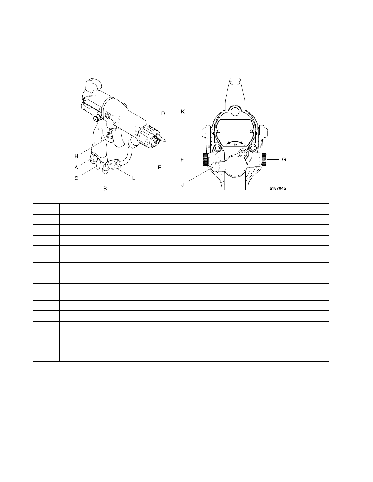
Theelectrostaticgunincludesthefollowingcontrols,indicators,andcomponents(seeFig.1).Forinformation
onSmartguns,alsoseeSmartGuns,page9.
Figure1GunOverview
Item
Item Item
A
Indicators,
Indicators, Indicators,
Description
Description Description
AirSwivelInlet1/4npsm(m)left-handthread,forGracogroundedairsupplyhose.
and
Components
and and
Components Components
Purpose
Purpose Purpose
BFluidInlet
C
D
EElectrode
FFanAirAdjustmentValve
G
H
J
K
LInlineFluidFilter
TurbineAirExhaust
AirCap/TipGuardand
SprayTip
AtomizingAirAdjustment
Valve
TriggerSafetyLockLockstriggertopreventgunfromspraying.
ESOn-OffValveTurnselectrostaticsON(I)orOFF(O).
ESIndicator(standard
gunonly;forSmart
gunindicator,see
OperatingMode,page9)
1/4npsm(m),foruidsupplyhose.
Barbedtting,forsuppliedexhausttube.
SeeSprayTipSelectionChart,page61,foravailablesizes.
Supplieselectrostaticchargetotheuid.
Adjustsfansizeandshape.Canbeusedtodecreasepatternwidth.
Adjustsatomizingairow.
LitwhenESisON(I).Colorindicatesalternatorfrequency.Seethe
LEDindicatortableintheGunSetupProcedure,page21.
Providesnalltrationofuid.Locatedinsideuidtubetting.
83A2495K
Page 9
GunOverview
Smart
Smart Smart
TheSmartGunmoduledisplayssprayingvoltage,
current,alternatorspeed,andthevoltagesetting(low
orhigh).Italsoallowstheusertochangetoalower
sprayingvoltage.Themodulehastwomodes:
•OperatingMode
•DiagnosticMode
Operating
Operating Operating
Bar
Bar Bar
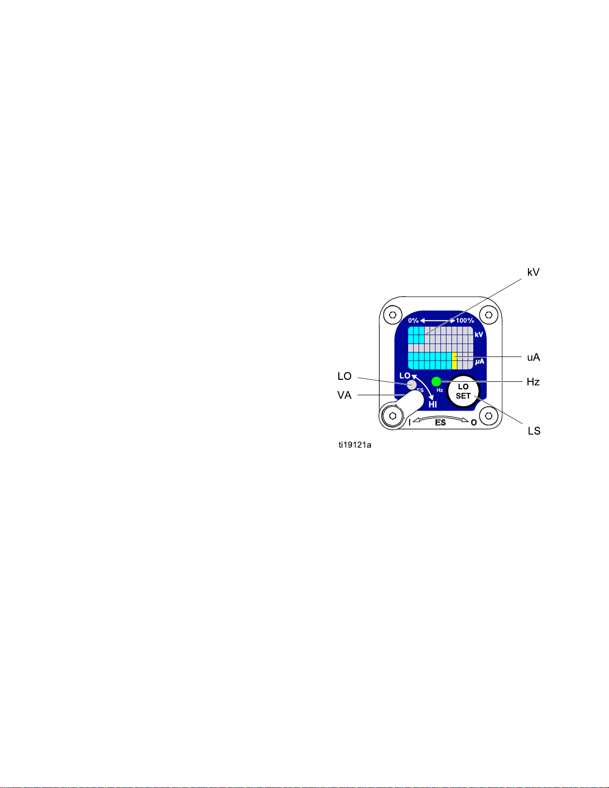
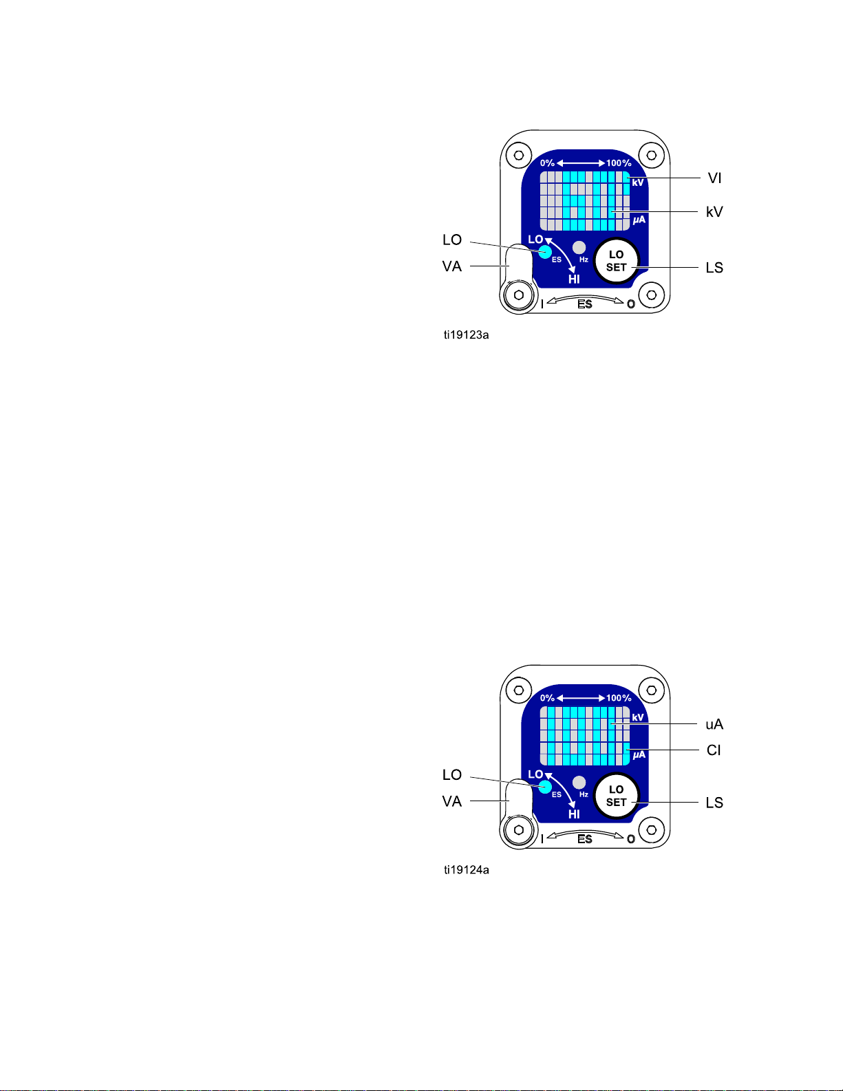
SeeFig.2andSmartGunKey,page11.The
OperatingModedisplaysgundataduringnormal
spraying.Thedisplayusesabargraphtoshowthe
voltagelevelinkiloVolts(kV)andthecurrentlevelin
microAmperes(uA).Thebargraphrangeisfrom0
to100%foreachvalue.
IftheuAbargraphLEDsareblue,thegunisready
tospray.IftheLEDsareyelloworred,thecurrentis
toohigh.Theuidmaybetooconductive,orsee
ElectricalTroubleshooting,page37forotherpossible
causes.
Guns
Guns Guns
Mode
Mode Mode
Graph
Graph Graph
Voltage
Voltage Voltage
Thevoltageadjustmentswitch(VA)allowsthe
operatortochangefromlowtohighvoltage.
•Thehighvoltagesettingisdeterminedbythe
maximumvoltageofthegunandisnotadjustable.
•Thelowvoltageindicator(LO)lights
whentheswitchissettoLO.Thelow
voltagesettingisuseradjustable.See
AdjustingtheLowVoltageSetting,page10.
NOTE:
NOTE: NOTE:
haslostcommunicationwiththepowersupply.See
ErrorDisplay,page10,forfurtherinformation.
Adjustment
Adjustment Adjustment
IftheErrordisplayappears,theSmartmodule
Switch
Switch Switch
Hz
Indicator
Hz Hz
Indicator Indicator
TheHzindicatorfunctionsthesameastheES
indicatoronstandardguns.Theindicatorlightsto
showthealternatorspeedstatus,andhasthree
colors:
•Greenindicatesthealternatorspeediscorrect.
•Iftheindicatorchangestoamberafteronesecond,
increasetheairpressure.
•Iftheindicatorchangestoredafteronesecond,
theairpressureistoohigh.Decreaseairpressure
untiltheindicatorisgreen.Tomaintainahigher
airpressure,installESOn/OffValveRestrictorKit
26A294.Then,adjustthepressureasneededto
ensuretoensuretheindicatorremainsgreen.
Figure2SmartGunModuleinOperatingMode
3A2495K9
Page 10

GunOverview
Error
Error Error
IftheSmartmodulelosescommunicationwith
thepowersupply,theErrordisplayappears,the
Hzindicatorturnsred,andtheSmartmoduleis
disabled.SeeFig.3andSmartGunKey,page11.
ThiscanoccurinOperatingModeorDiagnostic
Mode.SeeElectricalTroubleshooting,page37.
CommunicationmustberestoredtomaketheSmart
modulefunctional.
NOTE:
NOTE: NOTE:
appear.Ifthegunhasbeendisassembled,wait8
secondsbeforesprayingtoensurethatanError
conditionhasnotoccurred.
NOTE:
NOTE: NOTE:
displaywillnotappear.
Display
Display Display
Ittakes8secondsfortheErrordisplayto
Ifthereisnopowertothegun,theError
foryourgun.Continuepressingthebuttonuntilyou
reachthedesiredsetting.
NOTE:
NOTE: NOTE:
returntotheOperatingScreen.
NOTE:
NOTE: NOTE:
LockSymbol,page10.
Figure4LowVoltageSettingScreen(Unlocked)
Lock
Lock Lock
After2secondsofinactivitythedisplaywill
Thelowvoltagesettingmaybelocked.See
Symbol
Symbol Symbol
Figure3ErrorDisplay
Adjusting
Adjusting Adjusting
Thelowvoltagesettingisuseradjustable.Toaccess
thelowvoltagesettingscreenwheninOperating
Mode,presstheLOSETbutton(LS)momentarily.
Thescreenwilldisplaythecurrentlowvoltage
setting.SeeFig.4andSmartGunKey,page11.
Thepossiblerangesare:
•85kVguns:40–85kV
•60kVguns:30–60kV
SettheVoltageAdjustmentswitch(VA)toLO.Press
theLOSETbuttonrepeatedlytoincreasethesetting
inincrementsof5.Whenthedisplayreachesthe
maximumsettingitwillreturntotheminimumsetting
the
Low
the the
Voltage
Low Low
Voltage Voltage
Setting
Setting Setting
Thelowvoltagesettingmaybelocked.Whenlocked,
animage(LK)appearsonthescreen.SeeFig.5
andSmartGunKey,page11.
•WheninHImode,thelowvoltagesettingisalways always
locked.ThelocksymbolwillappearwhentheLO
SETbuttonispressed.
•WheninLOmode,thelocksymbolwill
only
only only
appearifthelockisenabled.See
LowVoltageLockScreen,page13,tolockor
unlockthelowvoltagesetting.
Figure5LowVoltageSettingScreen(Locked)
always
103A2495K
Page 11

GunOverview
Smart
Smart Smart
Table
Table Table
Item
Item Item
VA
LO
kV
uA
LSLOSETbuttonPressmomentarilytoentertheLowVoltageSettingscreen.
Gun
Key
Gun Gun
Key Key
Key
for
Figs.
1 11Key Key
for for
Description
Description Description
VoltageAdjustmentSwitchTwo-positionswitchsetsSmartgunvoltagetolowsetting(LO)or
LowVoltageMode
Indicator
Voltage(kV)DisplayDisplaysactualsprayingvoltageofthegun,inkV.InOperatingMode,
Current(uA)DisplayDisplaysactualsprayingcurrentofthegun,inuA.InOperatingMode,
2–9.
Figs. Figs.
2–9. 2–9.
Purpose
Purpose Purpose
highsetting(HI).ThisswitchisfunctionalinOperatingModeandin
DiagnosticMode.
Lights(blue)whentheSmartgunissettoLowVoltage.
displayisabargraph.InDiagnosticMode,voltageisdisplayedas
anumber.
displayisabargraph.InDiagnosticMode,currentisdisplayedas
anumber.
Pressandholdforapproximately5secondstoenterorexitDiagnostic
Mode.
WhileinDiagnosticMode,pressmomentarilytoadvancethrough
screens.
WhileontheLowVoltageLockScreen(inDiagnosticMode),press
andholdtoturnthelockonoroff.
LVLowVoltageDisplayDisplaysthelowvoltagesettingasanumber.Thesettingcanbe
changed.SeeFig.4.
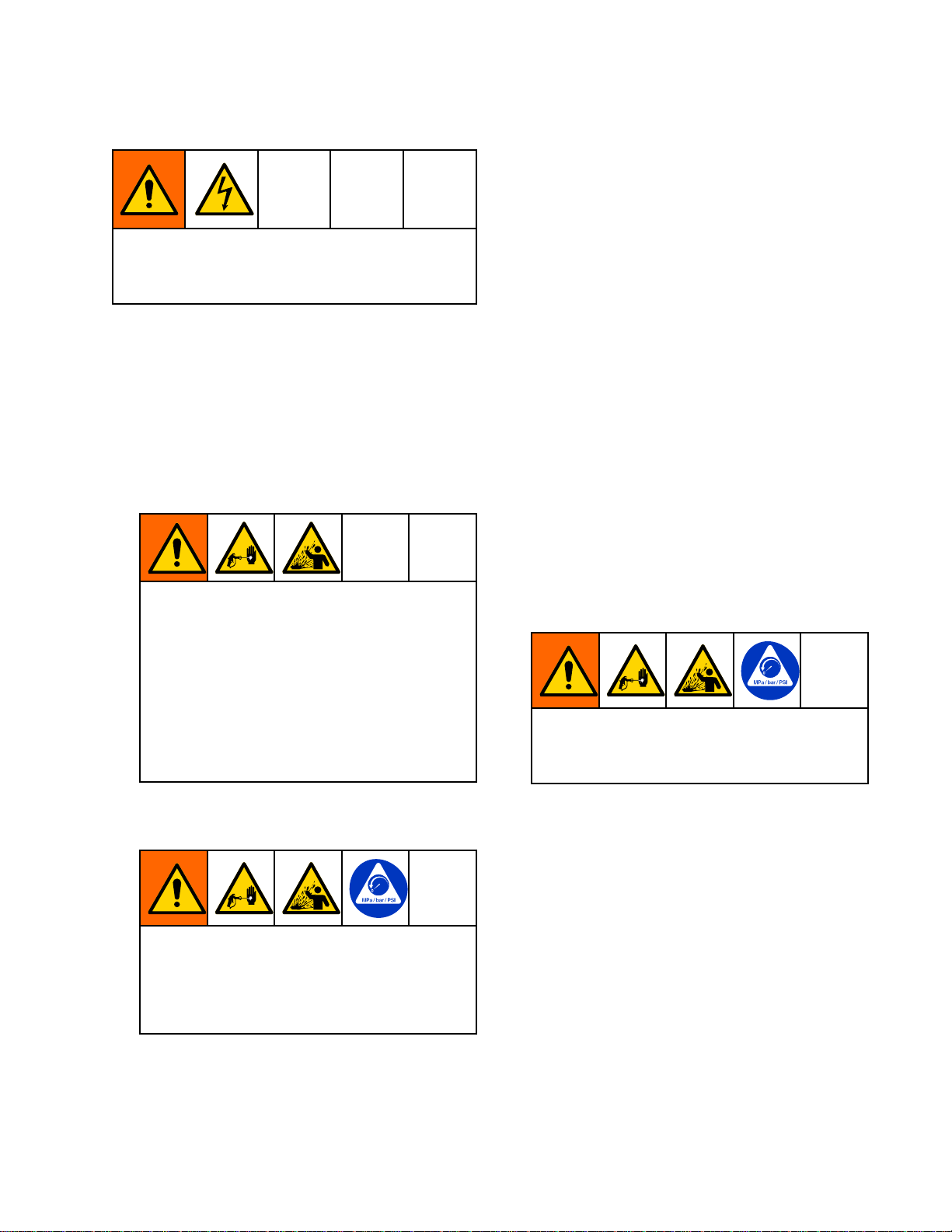
LKLowVoltageLocked
LD
ERErrorDisplay
VIVoltageIndicator
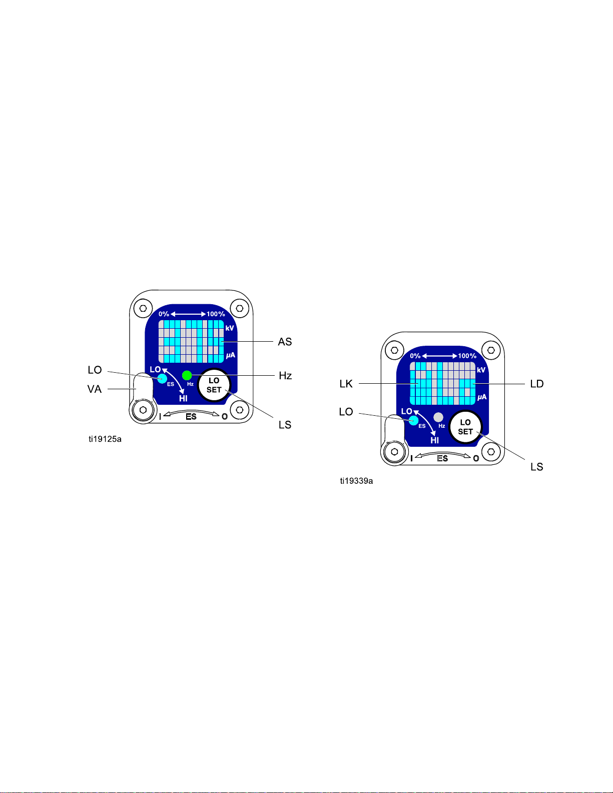
CICurrentIndicatorInDiagnosticMode,thetwobottomrightLEDsofthescreenlight,
ASAlternatorSpeedDisplayInDiagnosticMode,Hzlevelisdisplayedasanumber.SeeFig.8.
Hz
LODisplayAppearsontheLowVoltageLockScreen.SeeFig.9.
AlternatorSpeedIndicatorInOperatingMode,indicatorcolorvariestoshowthealternatorspeed
Appearsifthelowvoltagesettingislocked.SeeFig.5andFig.9.
AppearsiftheSmartmodulelosescommunicationwiththepower
supply.SeeFig.3.
InDiagnosticMode,thetwotoprightLEDsofthescreenlight,
indicatingthatthevaluedisplayedisinkV.SeeFig.6.
indicatingthatthevaluedisplayedisinuA.SeeFig.7.
status:
•Greenindicatesthealternatorspeedisatthecorrectlevel.
•Iftheindicatorchangestoamberafteronesecond,thealternator
speedistoolow.
•Iftheindicatorchangestoredafteronesecond,thealternatorspeed
istoohigh.TheindicatoralsoturnsrediftheErrordisplayappears.
InDiagnosticMode,theindicatorisgreenwhenintheAlternator
Speed(Hertz)screen.
3A2495K
11
Page 12
GunOverview
Diagnostic
Diagnostic Diagnostic
DiagnosticModeincludesfourscreenswhichdisplay
gundata:
•Voltage(kiloVolts)Screen
•Current(microAmperes)Screen
•AlternatorSpeed(Hertz)Screen
•LowVoltageLockScreen
NOTE:
NOTE: NOTE:
lowvoltagesetting;thesettingisnotadjustablein
DiagnosticMode.However,thevoltageadjustment
switch(VA)canbesettoHIorLOinOperatingMode
andinDiagnosticMode.
ToenterDiagnosticMode,pressandholdtheLOSET
(LS)buttonforapproximately5seconds.Thedisplay
willgototheVoltage(kiloVolts)Screen,page12.
Toadvancetothenextscreen,presstheLOSET
buttonagain.
ToexitDiagnosticMode,pressandholdtheLOSET
buttonforapproximately5seconds.Thescreenwill
returntoOperatingMode.
NOTE:
NOTE: NOTE:
Mode,thelastscreenviewedwillbedisplayedwhen
thegunisretriggered.
NOTE:
NOTE: NOTE:
fromtheLowVoltageLockScreen.See
LowVoltageLockScreen,page13fordetails.
Mode
Mode Mode
YoumustbeinOperatingModetoadjustthe
IfthegunisdetriggeredwhileinDiagnostic
DiagnosticModecannotbeexited
Figure6Voltage(kiloVolts)Screen
Current
Current Current
TheCurrent(microAmperes)Screenisthesecond
screenintheDiagnosticMode.SeeFig.7and
SmartGunKey,page11.Toenterthisscreen,press
theLOSETbuttonwhileintheVoltage(kiloVolts)
Screen.
Thisscreendisplaysthesprayingcurrentofthegun
asanumber(uA),roundedtothenearest5uA.The
twobottomrightLEDs(CI)ofthedisplaypanellight,
indicatingthattheCurrent(microAmperes)Screen
isdisplayed.Thedisplayisareadoutandcannot
bechanged.
(microAmperes)
(microAmperes) (microAmperes)
Screen
Screen Screen
Voltage
Voltage Voltage
TheVoltage(kiloVolts)Screenistherstscreento
appearafterenteringDiagnosticMode.SeeFig.6
andSmartGunKey,page11.Toenterthisscreen,
pressandholdtheLOSETbuttonforapproximately
5secondswhileintheOperatingMode.
Thisscreendisplaysthesprayingvoltageofthe
gunasanumber(kV),roundedtothenearest5kV.
ThetwotoprightLEDs(VI)ofthedisplaypanel
light,indicatingthattheVoltage(kiloVolts)Screen
isdisplayed.Thedisplayisareadoutandcannot
bechanged.
PresstheLOSETbuttontoadvancetothe
Current(microAmperes)Screen,page12.Press
andholdforapproximatelyvesecondstoreturnto
OperatingMode.
(kiloVolts)
(kiloVolts) (kiloVolts)
Screen
Screen Screen
PresstheLOSETbuttontoadvancetothe
AlternatorSpeed(Hertz)Screen,page13.Press
andholdforapproximatelyvesecondstoreturnto
OperatingMode.
Figure7Current(microAmperes)Screen
12
3A2495K
Page 13
GunOverview
Alternator
Alternator Alternator
TheAlternatorSpeed(Hertz)Screenisthethird
screenintheDiagnosticMode.SeeFig.8and
SmartGunKey,page11.Toenterthisscreen,
presstheLOSETbuttonwhileintheCurrent
(microAmperes)Screen.
Thisscreendisplaysthealternatorspeedasa3digit
number(AS),roundedtothenearest10Hz.The
displayisareadoutandcannotbechanged.Ifthe
alternatorspeedisgreaterthan999Hz,thedisplay
willshow999.
TheHzindicatorlightsgreentoshowthatyouare
viewingtheAlternatorSpeed(Hertz)Screen.
PresstheLOSETbuttontoadvancetothe
LowVoltageLockScreen,page13.Pressandhold
forapproximately5secondstoreturntoOperating
Mode.
Speed
Speed Speed
(Hertz)
(Hertz) (Hertz)
Screen
Screen Screen
Low
Voltage
Low Low
Voltage Voltage
TheLowVoltageLockScreenisthefourth
screenintheDiagnosticMode.SeeFig.9and
SmartGunKey,page11.Toenterthisscreen,press
theLOSETbuttonwhileintheAlternatorSpeed
(Hertz)Screen.
ThisscreendisplaysthestatusoftheLowVoltage
Lock.Ifthesettingislocked,thelockimage(LK)
appearstotheleftoftheLodisplay(LD).Ifthesetting
isunlocked,thelockimagedoesnotappear.
Tochangethelockstatus,pressandholdthe
LOSETbuttonuntilthelockimageappearsor
disappears.Ifthelockisset,theimagewillalso
appearontheLowVoltageSettingScreenwhenin
lowvoltagemode(seeFig.4).
NOTE:
NOTE: NOTE:
screen,becausepressingandholdingtheLOSET
buttonisusedtoturnthelockonoroff.Toexit,
pressLOSETmomentarilytoreturntotheVoltage
(kiloVolts)Screen,thenexitDiagnosticModefrom
there.
DiagnosticModecannotbeexitedfromthis
Lock
Screen
Lock Lock
Screen Screen
Figure8AlternatorSpeed(Hertz)Screen
Figure9LowVoltageLockScreen
3A2495K13
Page 14

Installation
Installation
Installation Installation
Installingandservicingthisequipmentrequires
accesstopartswhichmaycauseelectricshock
orotherseriousinjuryifworkisnotperformed
properly.
•Donotinstallorservicethisequipmentunless
youaretrainedandqualied.
•Besureyourinstallationcomplieswithlocal,
state,andnationalcodesfortheinstallation
ofelectricalapparatusinaClassI,Div.I,
hazardouslocationoraGroupII,ZoneI
explosiveatmospherelocation.
•Complywithalllocalcodesandregulations.
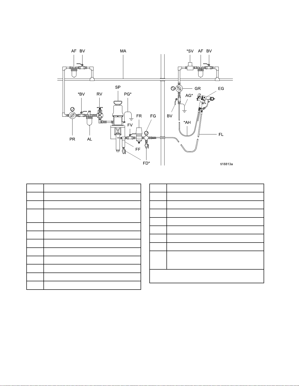
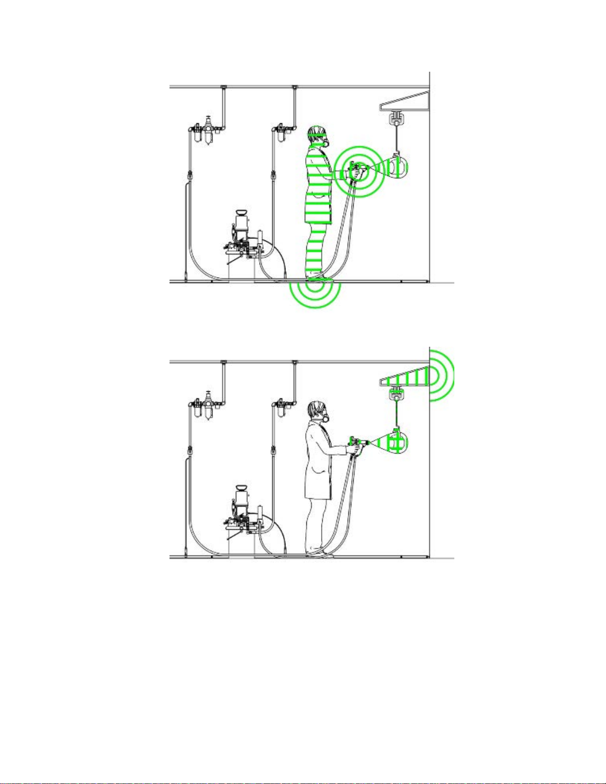
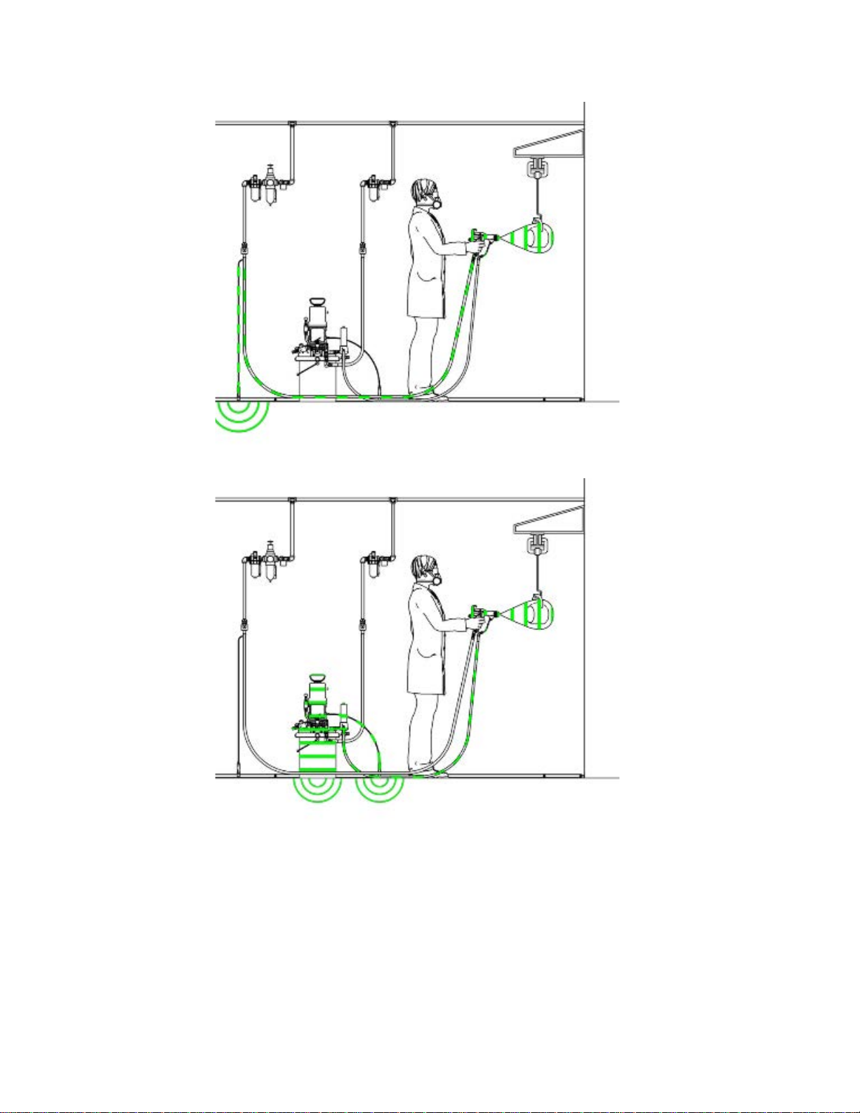
Fig.10(TypicalInstallation)showsatypical
electrostaticair-assistedspraysystem.Itisnotan
actualsystemdesign.Forassistanceindesigning
asystemtosuityourparticularneeds,contactyour
Gracodistributor.
Warning
Warning Warning
Sign
Sign Sign
Ventilate
Ventilate Ventilate
Donotoperatethegununlessventilatingairowis
abovetheminimumrequiredvalue.Providefresh
airventilationtoavoidthebuildupofammableor
toxicvaporswhenspraying,ushing,orcleaning
thegun.Interlockthegunairanduidsupply
topreventoperationunlessventilatingairowis
abovetheminimumrequiredvalue.
Thesprayboothmusthaveaventilationsystem.
Electricallyinterlockthegunairanduidsupplywith
theventilatorstopreventgunoperationanytimethat
theventilationairowfallsbelowminimumvalues.
Checkandfollowalllocalcodesandregulations
regardingairexhaustvelocityrequirements.Verify
theoperationoftheinterlockatleastonceayear.
NOTE:Theminimumallowableairexhaust
velocityis60feet/minute(19linearmeters/minute).
High-velocityairexhaustwilldecreasetheoperating
efciencyoftheelectrostaticsystem.
the
Spray
the the
Spray Spray
Booth
Booth Booth
Mountwarningsignsinthesprayareawherethey
caneasilybeseenandreadbyalloperators.An
EnglishWarningSignisprovidedwiththegun.
14
3A2495K
Page 15
Air
Supply
Air Air
Supply Supply
Toreducetheriskofelectricshock,theairsupply
hosemustbeelectricallyconnectedtoatrueearth
ground.Use Use
Hose.
Hose. Hose.
1.SeeFig.10.UsetheGracoGroundedAirSupply
Hose(AH)tosupplyairtothegun.Thegunair
inletttinghasaleft-handthread.Theairsupply
hosegroundwire(AG)mustbeconnectedtoa
trueearthground.Donotconnecttheairsupply
hosetothegunairinletyet.
2.Installanairlinelter/waterseparator(AF)onthe
gunairlinetoensureadry,cleanairsupplytothe
gun.Dirtandmoisturecanruintheappearance
ofyournishedworkpieceandcancausethe
guntomalfunction.
Toreducetheriskofseriousinjurydueto
componentrupture,includingskininjection,
pumppressuremustbelimitedbythepumpair
regulator.Donotrelyonthegunuidregulator
tolimittheuidpressuretothegun.
Line
Line Line
Use
only
Graco
only only
Graco Graco
Grounded
Grounded Grounded
Air
Supply
Air Air
Supply Supply
Installation
4.Installableed-typeairvalve(BV)onthepump
airsupplyline.Thebleed-typeairvalve(BV)is
requiredinyoursystemtoshutoffairtothepump
andrelieveairtrappedbetweenthevalveand
thepumpaftertheairregulatorisshutoff.Install
anadditionalbleed-typeairvalveonthemainair
line(MA)toisolatetheaccessoriesforservicing.
5.Installanairbleedvalve(BV)oneachgunair
supplylinetoshutoffairtothegun(s)andrelieve
airtrappedbetweenthevalveandthegunafter
theairregulatorisshutoff.
Fluid
Fluid Fluid
1.Blowouttheuidline(FL)withairandushit
2.Installauidpressureregulator(FR)ontheuid
3.Installauidlter(FF)nearthepumpoutlet,to
Supply
Supply Supply
withsolvent.Usesolventwhichiscompatible
withtheuidtobesprayed.Donotconnectthe
uidsupplylinetothegunuidinletyet.
linetocontroluidpressuretothegun.
removeparticlesandsedimentwhichcouldclog
thespraynozzle.
NOTE:
NOTE: NOTE:
additionalltration.
Thegunincludesaninlineuidlterfor
Line
Line Line
Theuidsupplypumpmustbepreventedfrom
producingauidpressuregreaterthanthe
3000psi(21MPa,210bar)
FluidPressure
supplypressuretoa30:1ratiopumpmustnot
exceed100psi(0.7MPa,7bar).
3.Installbleed-typeairregulators(PR,GR)on
thepumpandgunairsupplylinestocontrolair
pressuretothepumpandgun.
Trappedaircancausethepumptocycle
unexpectedly,whichcanresultinserious
injury,includingskininjectionandsplashing
uidintheeyesorontheskin.Donotoperate
theequipmentwithoutthebleed-typeairvalve
(BV)installed.
ofthegun.Forexample,theair
MaximumWorking
Toreducetheriskofseriousinjury,including
skininjectionandsplashinguidintheeyesor
ontheskin,donotoperateequipmentwithout
theuiddrainvalve(FD)installed.
4.Theuiddrainvalve(FD)isrequiredinyour
systemtoassistinrelievinguidpressureinthe
displacementpump,hose,andgun.Triggering
theguntorelievepressuremaynotbesufcient.
Installadrainvalveclosetothepump'suid
outlet.
3A2495K15
Page 16
Installation
NON
HAZARDOUS
NON NON
- --HAZARDOUS HAZARDOUS
LOCATION
LOCATION LOCATION
HAZARDOUS
HAZARDOUS HAZARDOUS
LOCATION
LOCATION LOCATION
Figure10TypicalInstallation
Typical
Typical Typical
Item
Item Item
AF
AG*GunAirHoseGroundWire
AH*GracoGroundedAirHose(left-hand
ALPumpAirLineLubricator
BV*PumpBleed-TypeAirShutoffValve
EGElectrostaticAirSprayGun
FD*
FFFluidFilter
FGFluidPressureGauge
FL
FRFluidPressureRegulator
Installation
Installation Installation
Description
Description Description
AirFilter/WaterSeparator
threads)
FluidDrainValve
FluidSupplyLine
Key
Key Key
Item
Item Item
FV
GRGunAirPressureRegulator
MA
PG*PumpGroundWire
PRPumpAirPressureRegulator
RVPumpRunawayValve
SPSupplyPump
SV*VentilationFanInterlockSolenoidValve
*Theseitemsarerequiredforsafeoperation.They
mustbepurchasedseparately.
Description
Description Description
FluidShutoffValve
MainAirSupplyLine
NOTE:
NOTE: NOTE:
aGracoaccessory.
Thesolenoidvalveisnotofferedas
163A2495K
Page 17
Grounding
Grounding Grounding
Theequipmentmustbegroundedtoreducethe
riskofstaticsparkingandelectricshock.Electric
orstaticsparkingcancausefumestoigniteor
explode.Impropergroundingcancauseelectric
shock.Groundallequipment,personnel,objects
beingsprayed,andconductiveobjectsinorclose
tothesprayarea.Theresistancemustnotexceed
1megohm.Groundingprovidesanescapewire
fortheelectriccurrent.
Whenoperatingtheelectrostaticgun,any
ungroundedobjects(suchaspeople,containers,and
tools)inthespraylocationcanbecomeelectrically
charged.
Thefollowingareminimumgroundingrequirements
forabasicelectrostaticsystem.Yoursystemmay
includeotherequipmentorobjectswhichmustbe
grounded.Yoursystemmustbeconnectedtoa
trueearthground.Checkgroundconnectionsdaily.
Checkyourlocalelectricalcodesandregulationsfor
detailedgroundinginstructions.
•
ElectrostaticAir-AssistedSprayGun:
thegunbyconnectingtheGracoGrounded
AirHosetothegun,andconnectingtheair
hosegroundwiretoatrueearthground.See
CheckGunElectricalGrounding,page24.
•
Pump/uidsource:
byconnectingitsgroundwiretoatrueearth
ground.
Groundthepump/uidsource
Installation
Ground
Allpersonsenteringthesprayarea:
•
shoeshavingconductivesolessuchasleather,
orwearpersonalgroundingstraps.Donot
wearshoeswithnon-conductivesolessuchas
rubberorplastic.Ifglovesarenecessary,wear
theconductiveglovessuppliedwiththegun.If
non-Gracoglovesareworn,cutoffngersorpalm
areaofglovestoensureyourhandcontactsthe
groundedgunhandle.Conductiveglovesand
footwearmustnotexceed100megohmperEN
ISO20344,EN1149–5.
•
Objectbeingsprayed:
cleanandgroundedatalltimes.
Keeptheworkpiecehangers
mustwear
•
Allelectricallyconductiveobjectsordevicesinthe
sprayarea:
•
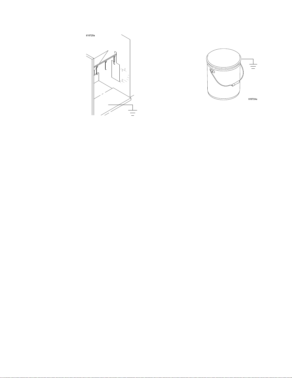
Fluidandwastecontainers:
wastecontainersinthesprayarea.Donotusepail
linersunlesstheyareconductiveandgrounded.
Whenushingthespraygun,thecontainerused
tocatchtheexcessuidmustbeelectrically
conductiveandgrounded.
•
Aircompressors:
tothemanufacturer'srecommendations.
•
Allairanduidlines
Useonlygroundedhoseswithamaximumof100
feet(30.5m)combinedhoselengthtoensure
groundingcontinuity
Theoorofthesprayarea:
•
conductiveandgrounded.Donotcovertheoor
withcardboardoranynon-conductivematerial
whichwouldinterruptgroundingcontinuity
mustbeproperlygrounded.
Groundalluidand
Groundtheequipmentaccording
mustbeproperlygrounded.
mustbeelectrically
3A2495K
17
Page 18
Installation
•
Flammableliquidsinthesprayarea:
inapproved,groundedcontainers.Donotuse
mustbekept
plasticcontainers.Donotstoremorethanthe
quantityneededforoneshift.
•
Allsolventpails:
metalcontainers,whichareconductive.Donot
useplasticcontainers.Useonlynon-ammable
solvents.Donotstoremorethanthequantity
neededforoneshift.
Useonlyapproved,grounded
183A2495K
Page 19
Installation
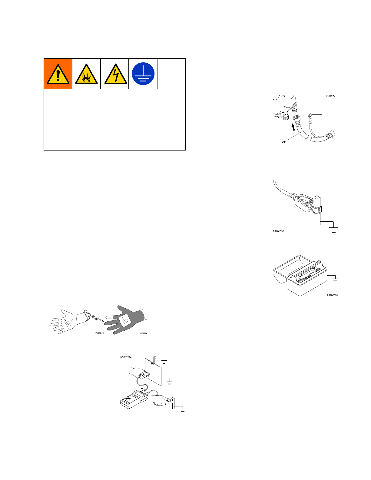
Figure11GroundtheOperatorOperatorisgroundedthroughthegunhandleand
conductiveshoes.
Figure12GroundtheObjectbeingSprayedObjectbeingsprayedisgroundedthroughcontact
withthehangerandconveyorsystem.
3A2495K19
Page 20
Installation
Figure13GroundtheGunGunisgroundedthroughtheconductiveairhose.
Figure14GroundtheFluidSupplyFluidsupplylineandsourcemustbegrounded.
203A2495K
Page 21
GunSetup
Gun
Gun Gun
Gun
Gun Gun
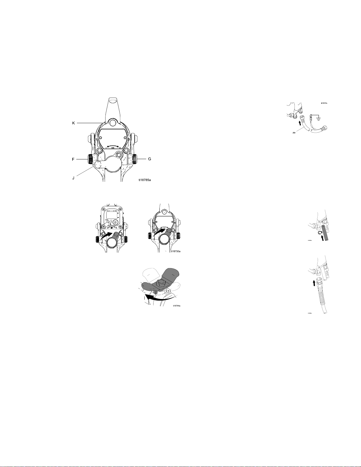
Seethegurebelowtolocatetheelectrostaticgun
controls.
Figure15ElectrostaticGunControls
1.TurnOFF(O)theESOn-Offswitch(J).
Setup
Setup Setup
Setup
Setup Setup
Procedure
Procedure Procedure
4.ConnecttheGracogroundedairhosetothegun
airinlet.Thegunairinletttinghasleft-hand
threads.
5.FollowallstepsunderGrounding,page17.
6.Followallstepsunder
CheckGunElectricalGrounding,page24.
Readingmustbelessthan1megohm.
7.Verifythatthematerialresistivitymeets
requirementsforelectrostaticspray.See
CheckFluidResistivity,page25.
8.Connecttheexhausttubeandsecurewiththe
clampprovided.
2.Shutofftheairbleedvalvetothegun.
3.Checkgunresistance.See
TestGunResistance,page32.
9.Connecttheuidhosetothegunuidinlet.
10.Flushifneeded.SeeFlushing,page28.
3A2495K
21
Page 22
GunSetup
Toreducetheriskofaskininjectioninjury,alwaysfollowthe
PressureReliefProcedure,page26,
beforeremovingorinstallingthespraytip,air
cap,ortipguard.
15.CheckthattheESOn-OffswitchisOFF(O).
11.Theuidoutputandpatternwidthdepend
onthesizeofthespraytip,theuid
viscosity,andtheuidpressure.Usethe
SprayTipSelectionChart,page61,asaguide
forselectingtheappropriatespraytipforyour
application.
12.Alignthespraytiptabwiththegrooveintheair
cap.Installthetip.
13.Installtheaircapandretainingring.Orientate
theaircapandtightentheretainingringsecurely.
14.Closetheatomizingairadjustmentvalve(G)and
thefanairadjustmentvalve(F).
16.Startthepump.Settheuidregulatorto400psi
(2.8MPa,28bar).
17.Sprayatestpattern.Examinetheparticlesizein
thecenterofthepattern(tailswillberemoved
instep21).Increasethepressureinsmall
increments.Sprayanotherpattern.Compare
particlesize.Continueincreasingpressureuntil
theparticlesizeremainsconstant.Donotexceed
3000psi(21MPa,210bar).
18.TurnON(I)theESOn-Offswitch.
22
3A2495K
Page 23

GunSetup
19.CheckthattheESindicator(K)[Hzindicatoron
Smartguns]islit.Seethefollowingtable.
Table
Table Table
Indicator
Indicator Indicator
Amber
20.Setthegunairregulatortodeliveraminimum
of45psi(0.32MPa,3.2bar)atthegunwhen
triggered,toensurefullsprayingvoltage.See
thetablebelow.
LED
2 22. ..LED LED
Color
Color Color
Green
Red
Indicator
Indicator Indicator
Whenspraying,theindicator
shouldremaingreen,indicating
sufcientairpressuretothe
alternatorturbine.
Iftheindicatorchangestoamber
afteronesecond,theairpressure
istoolow.Increaseairpressure
untiltheindicatorisgreen.
Iftheindicatorchangestored
afteronesecond,theairpressure
istoohigh.Decreaseairpressure
untiltheindicatorisgreen.To
maintainahigherapplicationair
pressure,installESOn/OffValve
RestrictorKit26A294.Adjustthe
pressureasneededtoensurethe
indicatorremainsgreen.
Colors
Colors Colors
Description
Description Description
21.Turntheatomizingairadjustmentvalve
counterclockwiseuntilanytailsdisappear.
22.Ifdesiredatomizationisnotachieved,change
thetipsize.Thesmallerthetiporice,thener
theatomization.
23.Sprayatestpiece.Examinetheedges
forcoverage.Ifwrapispoor,see
Troubleshooting,page35.
Table
Table Table
mm]
mm] mm]
Pressure
3 33. ..Pressure Pressure
Air
Hose
Air Air
Hose Hose
Length
Length Length
(using
(using (using
in ininft ftft(m) (m)
5/16
5/16 5/16
diameter
diameter diameter
15(4.6)52(0.36,3.6)
25(7.6)57(0.40,4.0)
50(15.3)68(0.47,4.7)
75(22.9)80(0.56,5.6)
100(30.5)90(0.63,6.3)
Drop
Drop Drop
Air
Air Air
(m)
in.
[8
in. in.
[8 [8
hose)
hose) hose)
NOTE:
NOTE: NOTE:
Regulator
Regulator Regulator
psi
in ininpsi psi
[with
gun
[with [with
gun gun
Setting
Setting Setting
(MPa,
(MPa, (MPa,
bar)
bar) bar)
triggered]
triggered] triggered]
openthefanairadjustmentvalveslightly.(Excessive
fanairowcancausepaintbuildupontheaircap.)
Ifanarrowerpatternisneededoccasionally,
3A2495K23
Page 24

GunSetup
Check
Check Check
MegohmmeterPartNo.241079(AA-seeFig.16)
isnotapprovedforuseinahazardouslocation.
Toreducetheriskofsparking,donotusethe
megohmmetertocheckelectricalgrounding
unless:
•Thegunhasbeenremovedfromthehazardous
•Orallsprayingdevicesinthehazardous
Failuretofollowthiswarningcouldcausere,
explosion,andelectricshockandresultinserious
injuryandpropertydamage.
GracoPartNo.241079Megohmmeterisavailable
asanaccessorytocheckthatthegunisproperly
grounded.
1.Haveaqualiedelectricianchecktheelectrical
2.TurnOFF(O)theESOn-Offswitch.
Gun
Gun Gun
location;
locationareturnedoff,ventilationfansinthe
hazardouslocationareoperating,andthereare
noammablevaporsinthearea(suchasopen
solventcontainersorfumesfromspraying).
groundingcontinuityofthespraygunandair
hose.
Electrical
Electrical Electrical
Grounding
Grounding Grounding
5.Makesurethegroundedairhoseisconnected
andthehosegroundwireisconnectedtoatrue
earthground.
6.Measuretheresistancebetweenthegunhandle
(BB)andatrueearthground(CC).Usean
appliedvoltageof500minimumto1000volts
maximum.Theresistanceshouldnotexceed1
megohm.SeeFig.16.
7.Iftheresistanceisgreaterthan1megohm,check
thetightnessofthegroundconnectionsandbe
suretheairhosegroundwireisconnectedtoa
trueearthground.Iftheresistanceisstilltoo
high,replacetheairhose.
3.Turnofftheairanduidsupplytothegun.Follow
thePressureReliefProcedure,page26.
4.Disconnecttheuidhose.
24
Figure16CheckGunElectricalGrounding
3A2495K
Page 25

GunSetup
Check
Check Check
Toreducetheriskofre,explosion,orelectric
shock,checktheuidresistivityinanon-hazardous
locationonly.ResistanceMeter722886andProbe
722860arenotapprovedforuseinahazardous
location.
Checkthattheresistivityoftheuidbeingsprayed
meetstherequirementsforanelectrostaticairspray
system.GracoPartNo.722886ResistanceMeter
and722860Probeareavailableasaccessories.
Followtheinstructionsincludedwiththemeterand
probe.
Fluidresistivityreadingsofatleast20megohms-cm
generallyprovidethebestelectrostaticresultsand
arerecommended.
Table
Table Table
Fluid
Fluid Fluid
Fluid
4 44. ..Fluid Fluid
Resistivity
Resistivity Resistivity
Resistivity
Resistivity Resistivity
Megohms Megohms
Levels
Levels Levels
Megohms
cm
- --cm cm
Check
Check Check
Aviscositycupandstopwatchareneededtocheck
uidviscosity.
1.Completelysubmergetheviscositycupin
2.Watchthestreamofuidcomingfromthebottom
3.Recordtheuidtype,elapsedtime,andsizeof
4.Iftheviscosityistoohighortoolow,contactthe
Flush
Flush Flush
Theequipmentwastestedinuidatthefactory.To
avoidcontaminatingyouruid,ushtheequipment
withacompatiblesolventbeforeusingtheequipment.
SeeFlushing,page28.
Fluid
Fluid Fluid
theuid.Liftthecupoutquickly,startingthe
stopwatchassoonasthecupiscompletely
removed.
ofthecup.Assoonasthereisabreakinthe
stream,shutoffthestopwatch.
theviscositycup.
materialsupplier.Adjustasnecessary.
Before
Before Before
Viscosity
Viscosity Viscosity
Using
Using Using
Equipment
Equipment Equipment
1–55–2020–200200–2000
Testelectrostatic
performance
Goodelectrostatic
results
Bestelectrostatic
results
Goodelectrostatic
results
3A2495K25
Page 26

Operation
Operation
Operation Operation
Pressure
Pressure Pressure
Thisequipmentstayspressurizeduntilpressure
ismanuallyrelieved.Tohelppreventserious
injuryfrompressurizeduid,suchasskininjection,
splashinguidandmovingparts,followthe
PressureReliefProcedurewhenyoustopspraying
andbeforecleaning,checking,orservicingthe
equipment.
1.TurnOFF(O)theESOn/Offswitch.
2.Engagethetriggerlock.
Relief
Relief Relief
Procedure
Procedure Procedure
4.Disengagethetriggerlock.
5.Triggerthegunintoagroundedmetalwaste
containertorelievetheuidpressure.
6.Engagethetriggerlock.
7.Openthepumpdrainvalve,havingawaste
containerreadytocatchthedrainage.Leave
thepumpdrainvalveopenuntilyouareready
tosprayagain.
3.Turnofftheairbleedvalvestotheuidsource
andtothegun.
8.Ifthespraytiporhoseiscompletelycloggedor
pressureisnotfullyrelieved,slowlyloosenthe
hoseendcoupling.Nowclearthespraytipor
hose.
263A2495K
Page 27

Operation
Startup
Startup Startup
FollowallstepsunderGunSetupProcedure,page21.
Checkthefollowinglistdaily,beforestartingto
operatethesystem,tohelpensureyouofsafe,
efcientoperation.
•Alloperatorsareproperlytrainedtosafelyoperate
anautomaticelectrostaticairspraysystemas
instructedinthismanual.
•Alloperatorsaretrainedinthe
PressureReliefProcedure,page26.
•Thewarningsignprovidedwiththegunismounted
inthesprayareawhereitcanbeeasilyseenand
readbyalloperators.
•Thesystemisthoroughlygroundedandthe
operatorandallpersonsenteringthesprayarea
areproperlygrounded.SeeGrounding,page17.
•Theconditionofthegun’selectrical
componentshasbeencheckedasinstructedin
ElectricalTests,page32.
•Ventilationfansareoperatingproperly.
•Workpiecehangersarecleanandgrounded.
•Alldebris(includingammableuidsandrags)is
removedfromthesprayarea.
•Allammableuidsinthespraybootharein
approved,groundedcontainers.
•Allconductiveobjectsinthesprayareaare
electricallygroundedandtheoorofthespray
areaiselectricallyconductiveandgrounded.
Shutdown
Shutdown Shutdown
Toreducetheriskofaninjury,followthe
PressureReliefProcedure,page26wheneveryou
areinstructedtorelievethepressure.
1.Flushthegun.SeeFlushing,page28.
2.FollowthePressureReliefProcedure,page26.
3.Hangthegunfromitshook,withthenozzle
pointingdown.
3A2495K
27
Page 28

Maintenance
Maintenance
Maintenance Maintenance
Daily
Daily Daily
Checkthefollowinglistdailyuponcompletionof
equipmentusage.
Care
Care Care
Flushthegun.SeeFlushing,page28.
Cleantheuidandairlinelters.
Cleantheoutsideofthegun.See
CleantheGunDaily,page30.
Cleantheaircapandspraytipdaily,at
aminimum.Someapplicationsrequire
morefrequentcleaning.Replacethespray
tipandaircapiftheyaredamaged.See
CleantheGunDaily,page30.
Checktheelectrodeandreplace
ifbrokenordamaged.See
ElectrodeReplacement,page41.
Checkforuidleakagefromthegunanduid
hoses.Tightenttingsorreplaceequipment
asneeded.
Checkelectricalgrounding.See
CheckGunElectricalGrounding,page24.
and
Cleaning
and and
Cleaning Cleaning
Checklist
Checklist Checklist
Flushing
Flushing Flushing
•Flushbeforechanginguids,beforeuidcandry
intheequipment,attheendoftheday,before
storing,andbeforerepairingequipment.
•Flushatthelowestpressurepossible.Check
connectorsforleaksandtightenasnecessary.
•Flushwithauidthatiscompatiblewiththeuid
beingdispensedandtheequipmentwettedparts.
Toreducetheriskofre,explosion,orelectric
shock:
•TurnOFF(O)theESOn-Offswitchbefore
ushingthegun.
•Alwaysgroundequipmentandwastecontainers.
•Flushequipmentonlyinawell-ventilatedarea.
•UseonlyGroupIIAushingmaterials.
Non-ignitableuidsarepreferred.
•Toavoidstaticsparkingandinjuryfrom
splashing,alwaysushatthelowestpossible
pressure.
NOTICE
NOTICE NOTICE
Donotusemethylenechlorideasaushingor
cleaningsolventwiththisgunasitwilldamage
nyloncomponents.
1.TurnOFF(O)theESOn-Offswitch.
2.FollowthePressureReliefProcedure,page26.
3.Removeandcleantheaircapandspraytip.
283A2495K
Page 29

Maintenance
4.Changetheuidsourcetosolvent,ordisconnect
theuidlineandconnectasolventsupplyline
tothegun.
5.Pointthegunintoagroundedmetalpail.Flush
untilcleansolventowsfromthegun.
6.FollowthePressureReliefProcedure,page26.
Engagethetriggerlock.
7.Shutoffordisconnectthesolventline.
8.Alignthespraytiptabwiththegrooveintheair
cap.Checktheconditionofthetipgasket(27a),
andreplaceifdamaged.Installthetip.
9.Reinstalltheaircap,tipguard,andretainingring.
10.Hangthegunfromitshook,withthenozzle
pointingdown.
11.Whenreadytosprayagain,reconnect
theuidsupplyline.Followthe
GunSetupProcedure,page21.
3A2495K29
Page 30

Maintenance
Clean
Clean Clean
•Cleanallpartswithanon-conductive,compatible
•Fluidintheairpassagescouldcausethegunto
1.TurnOFF(O)theESOn-Offswitch.
2.FollowthePressureReliefProcedure,page26.
3.Removetheaircap/tipguardandspraytip.
the
Gun
the the
Gun Gun
solvent.Conductivesolventscancausethegun
tomalfunction.
malfunctionandcoulddrawcurrentandreduce
theelectrostaticeffect.Fluidinthepowersupply
cavitycanreducetheturbinelife.Whenever
possible,pointthegundownwhencleaningit.
Donotuseanycleaningmethodwhichcould
allowuidintothegunairpassages.
Daily
Daily Daily
NOTICE
NOTICE NOTICE
6.Cleantheoutsideofthegunwithacompatible
solvent.Useasoftcloth.Pointthegundownto
preventsolventfromenteringthegunpassages.
Donotimmersethegun.
4.Flushthegun,seeFlushing,page28.
5.FollowthePressureReliefProcedure,page26.
303A2495K
Page 31

Maintenance
7.Cleantheaircap/tipguardandspraytipwitha
softbrushandcompatiblesolvent.
8.Ifnecessary,useatoothpickorothersofttoolto
cleantheaircapholes.Donotusemetaltools.
Daily
Daily Daily
1.FollowthePressureReliefProcedure,page26.
2.Cleantheuidandairlters.
3.Checkforuidleaks.Tightenallttings.
4.Cleanworkpiecehangers.Usenon-sparking
System
System System
tools.
Care
Care Care
9.Alignthespraytiptabwiththegrooveintheair
cap.Checktheconditionofthetipgasket(27a),
andreplaceifdamaged.Installthetip.
10.Installtheaircapandretainingring.Orientate
theaircapandtightentheretainingringsecurely.
5.Checkthemovementofthetriggerandvalves.
Lubricateifnecessary.
6.CheckGunElectricalGrounding,page24.
7.Hangthegunfromitshook,withthenozzle
pointingdown.
3A2495K31
Page 32

ElectricalTests
Electrical
Electrical Electrical
Electricalcomponentsinsidethegunaffect
performanceandsafety.Usethefollowing
procedurestotesttheconditionofthepowersupply
andgunbody,andelectricalcontinuitybetween
components.
Thegunbodyresistorcartridgeispartofthebody
andisnotreplaceable.Toavoiddestroyingthegun
body,donotattempttoremovethebodyresistor.
UsemegohmmeterPartNo.241079(AA)withan
appliedvoltageof500V.Connecttheleadsas
shown.
MegohmmeterPartNo.241079(AA-seeFig.17)
isnotapprovedforuseinahazardouslocation.
Toreducetheriskofsparking,donotusethe
megohmmetertocheckelectricalgrounding
unless:
Tests
Tests Tests
NOTICE
NOTICE NOTICE
Test
Test Test
1.Flushanddrytheuidpassage.
2.Measureresistancebetweentheelectrode
Gun
Gun Gun
needletip(25a)andtheairswivel(21).The
resistanceshouldbe:
•106–150megohmsfor60kVguns
•150–195megohmsfor85kVguns
Ifoutsidethisrange,goto
TestPowerSupplyResistance,page33.Ifin
range,seeElectricalTroubleshooting,page37for
otherpossiblecausesofpoorperformance.
Resistance
Resistance Resistance
•Thegunhasbeenremovedfromthehazardous
location;
•Orallsprayingdevicesinthehazardous
locationareturnedoff,ventilationfansinthe
hazardouslocationareoperating,andthereare
noammablevaporsinthearea(suchasopen
solventcontainersorfumesfromspraying).
Failuretofollowthiswarningcouldcausere,
explosion,andelectricshockandresultinserious
injuryandpropertydamage.
Figure17TestGunResistance
323A2495K
Page 33

ElectricalTests
Test
Test Test
1.Removethepowersupply(11).SeePower
2.Removethealternator(15)
3.Measureresistancefromthepowersupply's
4.Ifoutsidethisrange,replacethe
5.Ifyoustillhaveproblems,referto
6.Besurethespring(11a)isinplacebefore
Power
Power Power
SupplyRemovalandReplacement,page45.
fromthepowersupply.See
AlternatorRemovalandReplacement,page46.
groundstrips(EE)tothespring(11a).The
resistanceshouldbe:
•86–110megohmsfor60kVguns
•130–160megohmsfor85kVguns
powersupply.Ifinrange,goto
TestGunBarrelResistance,page34.
Electrical
Electrical Electrical
otherpossiblecausesofpoorperformance,or
contactyourGracodistributor.
reinstallingthepowersupply.
Supply
Supply Supply
Troubleshooting
Troubleshooting Troubleshooting
Resistance
Resistance Resistance
page
, ,,page page
37
37 37
, ,,for
Figure18TestPowerSupplyResistance
3A2495K33
Page 34

ElectricalTests
Test
Test Test
1.Insertaconductiverod(B)intothegunbarrel
2.Measuretheresistancebetweentheconductive
3.Iftheresistanceisstilloutsidetherange,
4.Iftheresistanceisinrange,replacethe
Gun
Gun Gun
(whichwasremovedforthepowersupplytest)
andagainstthemetalcontact(C)inthefrontof
thebarrel.
rod(B)andtheconductivering(9).The
resistanceshouldbe10–30megohms.Ifthe
resistanceisincorrect,makesurethemetal
contact(C)inthebarrelandtheconductivering
(9)arecleanandundamaged.
removetheconductivering(9)andmeasurethe
resistancebetweentheconductiverod(B)and
thewireleadatthebottomoftheconductivering
groove.
conductivering(9)withanewone.Insertthe
endsoftheconductiveringintotheslots(S)at
thefrontofthebarrel,thenpresstheringrmly
intothegroove(G).
Barrel
Barrel Barrel
Resistance
Resistance Resistance
Figure19TestGunBarrelResistance
Theconductivering(9)isaconductive(metal)
contactring,notasealingo-ring.Toreduce
theriskofre,explosion,orelectricshock:
•Donotremovetheconductiveringexcept
toreplaceit.
•Neveroperatethegunwithouttheconductive
ringinplace.
•Donotreplacetheconductiveringwith
anythingbutagenuineGracopart.
5.Iftheresistanceisstilloutsidetherange,replace
thegunbarrel.
343A2495K
Page 35

Troubleshooting
Troubleshooting
Troubleshooting Troubleshooting
Installingandservicingthisequipmentrequires
accesstopartswhichmaycauseanelectricshock
orotherseriousinjuryiftheworkisnotperformed
properly.Donotinstallorservicethisequipment
unlessyouaretrainedandqualied.
CheckallpossibleremediesintheTroubleshootingChartbeforedisassemblingthegun.
Spray
Spray Spray
NOTE:
NOTE: NOTE:
Problem
Problem Problem
Flutteringorspittingspray.
Irregularpattern.
Pattern
Pattern Pattern
Somespraypatternproblemsarecausedbytheimproperbalancebetweenairanduid.
Troubleshooting
Troubleshooting Troubleshooting
Cause
Cause Cause
Nouid.Rellsupply.
Airinuidsupply.Checkuidsource.Rell.
Fluidbuildup;partiallypluggedtip.
Worn/damagedtiporaircapholes.
Toreducetheriskofaskininjectioninjury,always
followthePressureReliefProcedure,page26,
wheneveryouareinstructedtorelievethe
pressure.
Solution
Solution Solution
Clean.See
CleantheGunDaily,page30.
Cleanorreplace.
Patternpushedtooneside;air
capgetsdirty.
Tailsinpattern.
Fluidbuilduponaircap/tipguard.
3A2495K35
Aircapholesplugged.
Airpressuretoolow.
Fluidpressuretoolow.Increase.
Airpressuretoohigh.Decrease.
Fluidpressuretoolow.Increase.
Aircapholesplugged.
Clean.See
CleantheGunDaily,page30.
Openatomizingairadjustment
valve.
Clean.See
CleantheGunDaily,page30.
Page 36

Troubleshooting
Gun
Gun Gun
Operation
Operation Operation
Problem
Problem Problem
Excessivesprayfog.
“OrangePeel”nish.
Fluidleaksfromtheuidpacking
area.
Airleaksfromthefrontofthegun.
Fluidleakagefromthefrontofthe
gun.
Troubleshooting
Troubleshooting Troubleshooting
Cause
Cause Cause
Atomizingairpressuretoohigh.
Fluidtoothin.
Atomizingairpressuretoolow.
Spraytipistoolarge.Usesmallertip.SeeSprayTip
Poorlymixedorltereduid.Remixorrelteruid.
Fluidtoothick.Reduceviscosity.
Wornuidneedlepackingsorrod.Replacepackings.SeeFluid
Airvalveisnotseatingproperly.
Wornordamageduidneedleball.SeeFluidNeedleReplacement,
Solution
Solution Solution
Closeatomizingairvalvepartway,
ordecreaseairpressureaslow
aspossible;minimum45psi(0.32
MPa,3.2bar)neededatgunfor
fullvoltage.
Increaseviscosityorincreaseuid
owrate.
Openatomizingairvalvemoreor
increasegunairinletpressure;
uselowestairpressurenecessary.
SelectionChart,page61.
NeedleReplacement,page44.
Replaceairvalve.See
AirValveRepair,page50.
page44.
Wornuidseathousing.SeeAirCap,SprayTip,andFluid
Loosespraytip.Tightenretainingring.
Damagedtipseal.
Gundoesnotspray.
Dirtyaircap.Damagedorpluggedaircap.
Excessivepaintwrapbackto
operator.
Lowuidsupply.Adduidifnecessary.
Damagedspraytip.Replace.
Dirtyorcloggedspraytip.
Damageduidneedle.SeeFluidNeedleReplacement,
Poorgrounding.
Incorrectdistancefromguntopart.Shouldbe8–12in.(200–300mm).
SeatHousingReplacement,page
40.
SeeAirCap,SprayTip,andFluid
SeatHousingReplacement,page
40.
Clean.See
CleantheGunDaily,page30.
page44.
Cleanaircap.See
CleantheGunDaily,page30.
SeeGrounding,page17.
363A2495K
Page 37

Troubleshooting
Electrical
Electrical Electrical
Problem
Problem Problem
Poorwrap.
Troubleshooting
Troubleshooting Troubleshooting
Cause
Cause Cause
ESOn/OffswitchisOFF(O).TurnON(I).
Gunairpressuretoolow(ES
indicatorisamber).
Atomizingairpressuretoohigh.Decrease.
Fluidpressuretoohigh.Decrease,orreplaceworntip.
Incorrectdistancefromguntopart.Shouldbe8-12in.(200-300mm).
Poorlygroundedparts.Resistancemustbe1megohmor
Faultygunresistance.
Lowuidresistivity.See
Fluidleaksfromtheuidneedle
packingsandcausesashort.
Faultyalternator.
ESOn/OffswitchisOFF(O).TurnON(I). ESorHzindicatorisnotlit.
Solution
Solution Solution
Checkairpressuretogun;
minimum45psi(0.32MPa,3.2
bar)neededatgunforfullvoltage.
less.Cleanworkpiecehangers.
See
TestGunResistance,page32.
CheckFluidResistivity,page25.
SeeFluidNeedleReplacement,
page44.
SeeAlternatorRemovaland
Replacement,page46.
Operatorgetsshockfrom
workpiece.
Nopower.
Operatornotgroundedorisnear
ungroundedobject.
Gunnotgrounded.SeeCheckGunElectrical
Workpiecenotgrounded.Resistancemustbe1megohmor
Checkpowersupply,alternator,
andalternatorribboncable.See
PowerSupplyRemovaland
Replacement,page45and
AlternatorRemovaland
Replacement,page46.
SeeGrounding,page17. Operatorgetsmildshock.
Grounding,page24,and
TestGunResistance,page32.
less.Cleanworkpiecehangers.
3A2495K37
Page 38

Troubleshooting
Problem
Problem Problem
Voltage/currentdisplaystaysred
(smartgunsonly).
ESorHzindicatorisamber.
ESorHzindicatorisred.
ErrordisplayappearsandHz
indicatorisred(Smartgunsonly).
Cause
Cause Cause
Gunistooclosetothepartbeing
sprayed.
Checkuidresistivity.See
Dirtygun.
Alternatorspeedistoolow.Increaseairpressureuntil
Alternatorspeedistoohigh.Decreaseairpressureuntil
Smartmodulehaslost
communicationwiththepower
supply.
Solution
Solution Solution
Gunshouldbe8–12in.(200–300
mm)fromthepart.
CheckFluidResistivity,page25.
SeeCleantheGunDaily,page30.
indicatorisgreen.Toavoid
over-atomization,usethe
atomizingairrestrictorvalveto
reducetheatomizingairtotheair
cap.
indicatorisgreen,orinstallES
On-OffwithAirRestrictor,which
limitstheairowtotheturbine.
Checkforgoodconnections
betweenSmartModuleand
powersupply.SeeSmartModule
Replacement,page51and
PowerSupplyRemovaland
Replacement,page45.
383A2495K
Page 39

Repair
Repair
Repair Repair
Prepare
Prepare Prepare
Installingandrepairingthisequipmentrequires
accesstopartsthatmaycauseelectricshockor
otherseriousinjuryiftheworkisnotperformed
properly.Donotinstallorservicethisequipment
unlessyouaretrainedandqualied.
Toreducetheriskofinjury,followthe
PressureReliefProcedure,page26,before
checkingorservicinganypartofthesystem
andwheneveryouareinstructedtorelievethe
pressure.
•Checkallpossibleremediesin
Troubleshooting,page35,beforedisassembling
thegun.
the
Gun
the the
Gun Gun
for
Service
for for
Service Service
•Useavisewithpaddedjawstopreventdamage
toplasticparts.
•Lubricatethesomeneedleassemblyparts(20)
andcertainuidttingswithdielectricgrease(57),
asspeciedinthetext.
•Lightlylubricateo-ringsandsealswithnon-silicone
grease.OrderPartNo.111265Lubricant.Donot
over-lubricate.
•OnlyusegenuineGracoparts.Donotmixoruse
partsfromotherProGunmodels.
•AirSealRepairKit24N789isavailable.The
kitmustbepurchasedseparately.Kitpartsare
markedwithanasterisk,forexample(3*).
1.Flushthegun.SeeFlushing,page28.
2.Relievethepressure.See
PressureReliefProcedure,page26.
3.Disconnectthegunairanduidlines.
4.Removethegunfromtheworksite.Repairarea
mustbeclean.
3A2495K39
Page 40

Repair
Air
Cap,
Air Air
Cap, Cap,
Spray
Spray Spray
Tip,
and
Tip, Tip,
Fluid
and and
Fluid Fluid
Seat
Seat Seat
Housing
Housing Housing
Replacement
Replacement Replacement
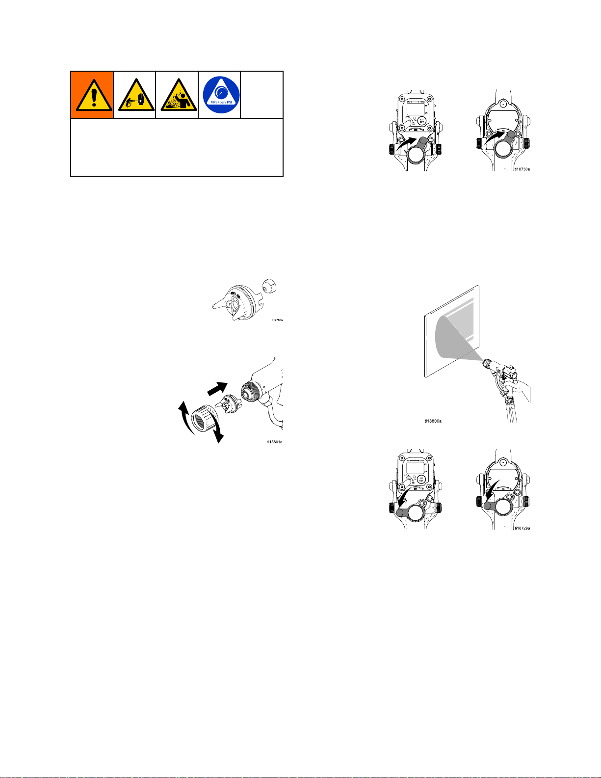
1.SeePreparetheGunforService,page39.
2.Removetheretainerring(22)andaircap/tip
guardassembly(25).
Figure20RemoveAirCap
3.Disassembletheaircapassembly.Checkthe
conditionoftheu-cup(22a),o-ring(25b),andtip
gasket(27a).Replaceanydamagedparts.
4.Toreplacetheelectrode(25a),see
ElectrodeReplacement,page41.
Theconductivering(9)isaconductivemetal
contactring,notasealingo-ring.Toreduce
theriskofre,explosion,orelectricshock:
•Donotremovetheconductiveringexcept
toreplaceit.
•Neveroperatethegunwithouttheconductive
ringinplace.
•Donotreplacetheconductiveringwith
anythingbutagenuineGracopart.
5.Triggerthegunandremovetheuidseathousing
(24),usingthemulti-tool(61).
Figure21DisassembleAirCapAssembly
Figure22TipGasket
Figure23ReplaceFluidSeatHousing
403A2495K
Page 41

Repair
NOTICE
NOTICE NOTICE
Donotovertightentheuidseathousing(24).
Overtighteningmaydamagethehousingand
thegunbarrel,resultinginimproperuid
shutoff.
6.Triggerthegunandinstalltheuidseathousing
(24).Tightenuntilsnug,then1/4turnmore.
7.Checkthatthespraytipgasket(27a)isinplace.
Alignthespraytiptabwiththegrooveintheair
cap(25).Installthespraytip(27)intheaircap.
8.Makesurethattheelectrode(25a)isinstalled
correctlyintheaircap.
9.Checkthattheaircapo-ring(25b)isinplace.
10.Checkthattheu-cup(22a)isinplaceonthe
retainingring(22).Thelipsoftheu-cupmust
faceforward.
NOTICE
NOTICE NOTICE
Toavoiddamagingthetipguard,orientthe
aircapassembly(25)beforetighteningthe
retainingring(22).Donotturntheaircap
whentheretainingringistight.
11.Orientatetheaircapandtightentheretaining
ringsecurely.
12.SeeTestGunResistance,page32.
Electrode
Electrode Electrode
Toreducetheriskofre,explosion,orelectric
shock,donotoperatethespraygunwithoutthe
electrodeinstalledintheaircap.
1.Followthestepsin
PreparetheGunforService,page39.
2.Removetheaircapassembly(25).See
AirCap,SprayTip,andFluidSeatHousing
Replacement,page40.
3.Pulltheelectrode(25a)outofthebackoftheair
cap,usinganeedle-nosepliers.
4.Pushthenewelectrodethroughtheaircaphole.
Makesuretheshortend(BB)oftheelectrode
engagesthehole(CC)inthebackoftheair
cap.Presstheelectrodeinplacermlywithyour
ngers.
5.Installtheaircapassembly.
6.FollowthestepsinTestGunResistance,page32.
Replacement
Replacement Replacement
Figure24ReplaceElectrode
3A2495K
41
Page 42
Repair
Fluid
Fluid Fluid
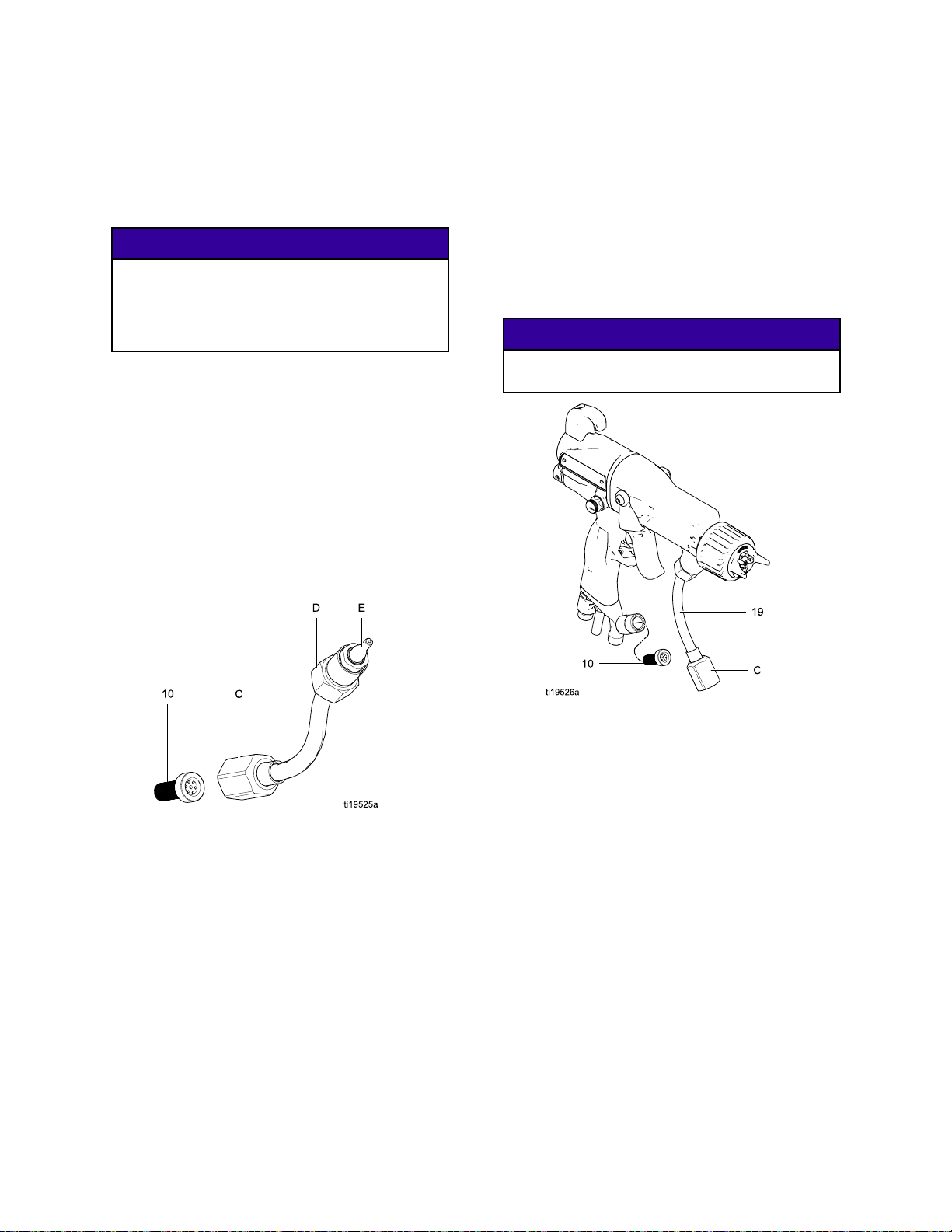
1.SeePreparetheGunforService,page39.
2.Disconnectthebottomuidtubenut(C).
3.Carefullyunscrewthetopuidtubenut(D).
4.Applydielectricgrease(57)totheentirelengthof
5.Applylowstrengthsealanttotheuidtubenut
6.Installtheuidtubeintothegunbarreland
7.Makesuretheuidlter(10)isinplaceinthe
Tube
Tube Tube
Becarefulnottodamagetheuidtube
assembly(19)whencleaningorinstalling
it,especiallythesealingsurface(E).Ifthe
sealingsurfaceisdamaged,theentireuid
tubeassemblymustbereplaced.
theplasticextensionontheuidtube.
threads.
tightenthetopnut(D)untilsnug,then1/2turn
tighter.Therewillbeagapbetweenthenutand
barrel.Donotover-tightenthenut.
uidtting.Tightenthebottomnut(C)securely
ontothetting.Makesurethetopnutremains
tight.
Removal
Removal Removal
and
Replacement
and and
Replacement Replacement
NOTICE
NOTICE NOTICE
Fluid
Fluid Fluid
1.SeePreparetheGunforService,page39.
2.Disconnectthebottomuidtubenut(C).
3.Removetheuidlter(10)fromtheuidtting.
4.Installtheuidlter(10)intheuidtting.Tighten
Filter
Filter Filter
Cleanorreplacethelter,asneeded.
thebottomnut(C)ontothettingandtorqueto
140–150in-lb(15.8–16.9N•m).Makesurethe
topnutremainstightat20–30in-lb(2.3–3.4N•m).
Besuretheuidtube(19)isnottwistedafter
tighteningthebottomnut(C).
Replacement
Replacement Replacement
NOTICE
NOTICE NOTICE
Figure25FluidTube
Figure26ReplaceFluidFilter
42
3A2495K
Page 43

Repair
Gun
Gun Gun
1.SeePreparetheGunforService,page39.
2.Disconnectthebottomuidtubenut(N).
3.Loosenthetwoscrews(6).
4.Holdthegunhandle(16)withonehandandpull
NOTE:
NOTE: NOTE:
removethealternator/powersupplyassemblyfrom
thebarrel.
Barrel
Barrel Barrel
Carefullyseparatethetubeassembly(T)from
thebracket(7).
Toavoiddamagingthepowersupply(11),
pullthegunbarrelstraightawayfromthegun
handle.Ifnecessary,gentlymovethegun
barrelfromsidetosidetofreeitfromthegun
handle.
thebarrel(1)straightoffthehandle.
Ifthepowersupplyremainsinthebarrel,
Removal
Removal Removal
NOTICE
NOTICE NOTICE
Gun
Gun Gun
1.Besurethegasket(5*)andgroundingspring
2.Makesurethespring(11a)isinplaceonthe
3.Tightenthetwoscrews(6)oppositelyandevenly
4.Makesuretheuidlter(10)isinplaceinthe
5.FollowthestepsinTestGunResistance,page32.
Barrel
Barrel Barrel
(37a)areinplace.Makesurethegasketair
holesarealignedproperly.Replacethegasketif
damaged.
tipofthepowersupply(11).Liberally Liberally
dielectricgrease(57)tothetipofthepower
supply.Placethegunbarrel(1)overthepower
supplyandontothegunhandle(16).
(aboutahalfturnpastsnug,or20in-lbs,2.3
N•m).
Toavoiddamagingthegunbarrel,donot
over-tightenthescrews(6).
uidtting.Tightenthebottomnut(N)ontothe
ttingandtorqueto140–150in-lb(15.8–16.9
N•m).Makesurethetopnutremainstight.
Installation
Installation Installation
Liberally
NOTICE
NOTICE NOTICE
apply
Figure27GunBarrelRemoval
Figure28GunBarrelInstallation
3A2495K43
Page 44

Repair
Fluid
Fluid Fluid
1.SeePreparetheGunforService,page39.
2.Removetheaircapassemblyanduidseat
3.Removethegunbarrel.See
4.Removethetriggerscrews(13)andtrigger(12).
5.Unscrewthespringcap(37).Removethespring
6.Besuretheseathousing(24)isremoved.Place
7.Usingtheexternalhexendoftheplasticmulti-tool
Needle
Needle Needle
housing.SeeAirCap,SprayTip,andFluidSeat
HousingReplacement,page40.
GunBarrelRemoval,page43.
(20a).
the2mmballendwrench(60)inthebackof
theuidneedleassembly.Pushthetoolforward
sothetwosegmentsoftheneedleengage,and
turnitcounterclockwiseabout12fullturnsto
unthreadtheneedle.
(61),carefullypushstraightontheuidneedle
ballfromthefrontofthebarreluntiltheuidseals
releasefromthebore.
Topreventneedleassemblyseparationor
damage,becertainneedleisdisengaged
beforeremoving.
Replacement
Replacement Replacement
NOTICE
NOTICE NOTICE
Figure29RemoveCapandSprings
8.Removetheuidneedleassemblyfromtheback
ofthegunbarrel.
9.Installtheuidneedleassemblyinthegunbarrel.
Pushinontheneedlewiththedriver(60)and
tighten.
10.Installthespring(20a).
11.Installthespringcap(37).Makesurethe
groundingspring(37a)isinplace.
12.Installthetrigger(12)andscrews(13).
13.Installthegunbarrel.See
GunBarrelInstallation,page43.
14.Installtheseathousingandaircapassembly.
SeeAirCap,SprayTip,andFluidSeatHousing
Replacement,page40.
15.SeeTestGunResistance,page32.
Figure30RemoveFluidNeedle
Figure31ReplaceFluidNeedle
44
3A2495K
Page 45

Repair
Power
Power Power
•Inspectthegunhandlepowersupplycavityfordirt
ormoisture.Cleanwithaclean,dryrag.
•Donotexposegasket(5)tosolvents.
1.SeePreparetheGunforService,page39.
2.SeeGunBarrelRemoval,page43.
3.Graspthepowersupply(11)withyourhand.
4.Inspectthepowersupplyandalternatorfor
5.Toseparatethepowersupply(11)fromthe
6.SeeTestPowerSupplyResistance,page33.
7.
Supply
Supply Supply
Becarefulwhenhandlingthepowersupply
(11)toavoiddamagingit.
Withagentlesidetosidemotion,freethepower
supply/alternatorassemblyfromthegunhandle
(16),thencarefullypullitstraightout.
Modelsonly,
fromthesocketatthetopofthehandle.
damage.
alternator(15),disconnectthe3-wireribbon
connector(PC)fromthepowersupply.
Modelsonly,
(40)fromthepowersupply.Slidethealternator
upandoffthepowersupply.
Replacethepowersupplyifnecessary.
Torepairthealternator,see
AlternatorRemovalandReplacement,page46.
Smartmodelsonly:
circuit(40)tothepowersupply.
Removal
Removal Removal
NOTICE
NOTICE NOTICE
disconnecttheexiblecircuit(40)
disconnectthe6–pinexiblecircuit
connectthe6–pinexible
and
Replacement
and and
Replacement Replacement
OnSmart
OnSmart
9.Insertthepowersupply/alternatorassemblyin
thegunhandle(16).Makesurethegroundstrips
(EE)makecontactwiththehandle.OnSmart
models,aligntheconnectorofthe6–pinexible
circuit(40)withthesocket(CS)atthetopofthe
handle.Pushtheconnectorsecurelyintothe
socketasyouslidethepowersupply/alternator
assemblyintothehandle.
Figure32ConnectFlexibleCircuit
10.Makesurethegasket(5*),groundspring
(37a),andpowersupplyspring(11a)are
inplace.Replacegasket(5*)ifdamaged.
Assemblethebarrel(1)tothehandle(16).See
GunBarrelInstallation,page43.
11.SeeTestGunResistance,page32.
NOTICE
NOTICE NOTICE
Topreventdamagetothecableandpossible
interruptionofthegroundcontinuity,bendthe
alternator’s3-wireribboncable(PC)upward
andback,sothebendfacesthepowersupply
andtheconnectorisatthetop.
8.Connectthe3-wireribbonconnector(PC)tothe
powersupply.Tucktheribbonforward,under
thepowersupply.Slidethealternator(15)down
ontothepowersupply(11).
Figure33PowerSupply
3A2495K45
Page 46

Repair
Alternator
Alternator Alternator
NOTE:
NOTE: NOTE:
ofoperation.OrderPartNo.24N706BearingKit.
Partsincludedinthekitaremarkedwithasymbol(♦).
1.SeePreparetheGunforService,page39.
2.Removethepowersupply/alternatorassembly
3.Measureresistancebetweenthetwoouter
4.Usingaatbladescrewdriver,prytheclip(15h)
5.Ifnecessary,rotatethefan(15e)soitsblades
Replacealternatorbearingsafter2000hours
anddisconnectthealternator.SeePowerSupply
RemovalandReplacement,page45.
terminalsofthe3-wireconnector(PC);itshould
be2.0–6.0ohms.Ifoutsidethisrange,replace
thealternatorcoil(15a).
offthehousing(15d).Removethecap(15f),
usingathinbladeorscrewdriver.
clearthefourbearingtabs(T)ofthehousing
(15d).
Removal
Removal Removal
and
Replacement
and and
Replacement Replacement
6.Pushthefanandcoilassembly(15a)outthe
frontofthehousing(15d).
Figure35AlternatorCross-Section
♦5isnotshownintheillustration.
Figure34FanOrientation
NOTICE
NOTICE NOTICE
Donotscratchordamagethemagnet(M)or
shaft(S).Donotpinchordamagethe3–wire
connector(PC)whendisassemblingand
reassemblingthebearings.
7.Holdthecoilassembly(15a)onaworkbench
withthefanendfacingup.Usingawideblade
screwdriver,prythefan(15e)offtheshaft(S).
8.Removethetopbearing(15b2).
9.Removethebottombearing(15b1).
10.Installthenewbottombearing(15b1♦)onthe
longendoftheshaft(S).Theattersideofthe
bearingmustfaceawayfromthemagnet(M).
Installinthecoil(15a)sothebearingbladesare
ushwiththesurfaceofthecoil.
11.Pressthenewtopbearing(15b2♦)ontotheshort
endoftheshaftsothebearingbladesareush
withthesurfaceofthecoil(15a).Theatterside
ofthebearingmustfaceawayfromthecoil.
463A2495K
Page 47

Repair
12.Holdthecoilassembly(15a)onaworkbench
withthefanendfacingup.Pressthefan(15e♦)
ontothelongendoftheshaft(S).Thefanblades
mustbeorientedasshown.
13.Carefullypressthecoilassembly(15a)intothe
frontofthehousing(15d♦)whilealigningthe
pinonthecoilwiththeslotinthehousing.The
3–wireconnector(PC)mustbepositionedbelow
thewidernotch(W)ofthehousingtabs,as
showninFig.35.Besurethecoilalignmentpins
(P)arepositionedasshowninFig.34.
14.Rotatethefan(15e)soitsbladesclearthefour
bearingtabs(T)atthebackofthehousing.
Ensurethatthebladesofthebottombearing
(15b1♦)alignwiththetabs.
15.Seatthecoilfullyintothehousing(15d♦).Secure
withtheclip(15h♦),ensuringthatitstabsengage
theslotsinthehousing.
16.Ensurethattheo-ring(15g)isinplace.Install
thecap(15f).
17.Installthealternatoronthepowersupply,and
installbothpartsinthehandle.SeePower
SupplyRemovalandReplacement,page45.
Figure36Alternator
3A2495K
47
Page 48
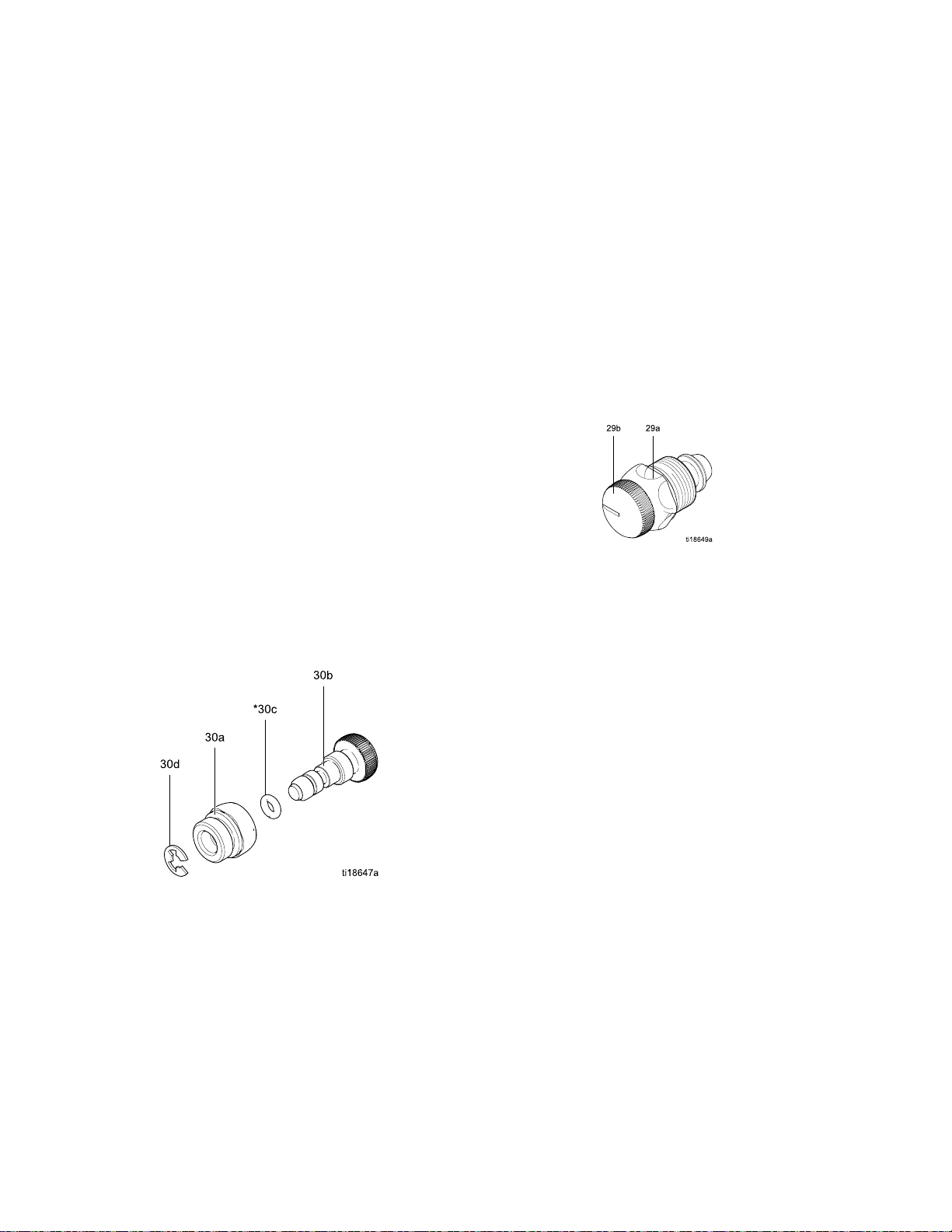
Repair
Fan
Air
Fan Fan
1.Followthestepsin
PreparetheGunforService,page39.
2.Placeawrenchontheatsofthevalveassembly
(30)andunscrewitfromthehandle(16).
NOTE:
NOTE: NOTE:
assembly(gotostep9)orasindividualparts
(steps3-9).
3.Removetheretainingring(30d).
4.Turnthevalveshaft(30b)counterclockwiseuntil
itcomesfreefromthevalvehousing(30a).
5.Removetheo-ring(30c).
6.Cleanallpartsandinspectforwearordamage.
NOTE:
NOTE: NOTE:
111265.Donotover-lubricate.
7.Whenreassemblingthefanairvalve(30),lightly
lubricatethevalvethreadsandscrewtheshaft
(30b)fullyintothehousing(30a)untilbottomed.
Installtheo-ring(30c*),lubricate,andunscrew
thevalvestemuntiltheo-ringentersthehousing.
8.Reassembletheretainingring(30d).Unscrew
thevalvestemfromthehousinguntilitisstopped
bytheretainingring.
9.Screwthevalveassembly(30)intothegun
handle(16),usingawrenchontheatsofthe
housing.Torqueto15in-lb(1.7N•m).
Adjustment
Air Air
Adjustment Adjustment
Youmayreplacethevalveasan
Usenon-siliconegrease,PartNo.
Valve
Valve Valve
Repair
Repair Repair
Atomizing
Atomizing Atomizing
Repair
Repair Repair
1.Followthestepsin
PreparetheGunforService,page39.
2.Placeawrenchontheatsofthevalveassembly
(29)andunscrewitfromthehandle(16).
3.Inspectthevalveassembly.Ifdamaged,install
anewvalve(29).
4.Beforeinstallingthevalveassemblyinthe
handle,unscrewthevalvestem(29b)fromthe
housing(29a)untilitstops.
5.Installthevalveassemblyintothegunhandle.
Torquethevalvehousing(29a)to15in-lb(1.7
N•m).
Figure38AtomizingAirAdjustmentValve
Air
Adjustment
Air Air
Adjustment Adjustment
Valve
Valve Valve
Figure37FanAirAdjustmentValve
483A2495K
Page 49

Repair
ES
On
Off
ES ES
On On
Valve
- --Off Off
Valve Valve
Repair
Repair Repair
1.Followthestepsin
PreparetheGunforService,page39.
2.Loosenthecaptivescrew(26p).Removethe
valve(26)fromthehandle.
3.Lubricatetheo-rings(26b*and26g*)with
non-siliconegrease,PartNo.111265.Donot
over-lubricate.
NOTE:
NOTE: NOTE:
lubricantontheo-ringscanbepushedintothe
gunairpassageandblemishthenishonthe
workpiece.
Donotover-lubricateparts.Excessive
4.Cleanandinspectpartsfordamage.Replace
ifnecessary.
NOTE:
NOTE: NOTE:
mustpointupward.
5.Reinstallthevalve.Torquethescrew(26p)to
15-25in-lb(1.7-2.8N•m).
Theprotrusionontheretainerplate(26f)
Figure39ESOn-OffValve
3A2495K49
Page 50

Repair
Air
Valve
Air Air
Valve Valve
Repair
Repair Repair
1.Followthestepsin
PreparetheGunforService,page39.
2.FollowthestepsinGunBarrelRemoval,page43.
3.Removethescrews(13)andtrigger(12).
4.RemovetheESOn-OffValve.See
ESOn-OffValveRepair,page49.
5.Removethespring(2).
6.Pushonthefrontoftheairvalveshafttoforceit
outthebackofthehandle.Inspecttherubber
seal(23a*)andreplaceifdamaged.
7.Inspecttheu-cup(3).Donotremovetheu-cup
unlessdamaged.Ifremoved,installthenewone
withitslipsfacingintothegunhandle(16).Place
theu-cupontheshaftoftheairvalvetohelpseat
itinthegunhandle.
8.Installtheairvalve(23)andspring(2)intothe
gunhandle(16).
9.InstalltheESOn-OffValve.See
ESOn-OffValveRepair,page49.
10.Installthetrigger(12)andscrews(13).
11.Followthestepsin
GunBarrelInstallation,page43.
Figure40InstallU-Cup
Figure41AirValve
503A2495K
Page 51

Repair
Smart
Smart Smart
IftheErrordisplayappears,theSmartModulehas
lostcommunicationwiththepowersupply.Checkfor
goodconnectionsbetweentheSmartModuleand
thepowersupply.
Ifthemodule’sLEDsarenotlighting,replacethe
module.
1.Followthestepsin
2.Removethepivotscrew(31e),o-ring(31f),and
3.Removetheremainingthreescrews(31d)from
4.PulltheSmartModuleoutthebackofthegun.
5.Removethegasket(31b).
6.Installanewgasket(31b)onthenewcartridge
7.Alignthemodule’sribboncable(RC)with
8.Installthepivotscrew(31e),o-ring(31f),and
9.Installthethreeremainingscrews(31d).Torque
Module
Module Module
PreparetheGunforService,page39.
ESHI/LOswitch(31c)atthebottomleftcornerof
theSmartModulecartridge(31a).
thecartridge.
Disconnecttheribboncable(RC)fromthe
connector(GC)inthegunhandle.
(31a).Makesurethenotchedcornersofthe
gasketareatthetop.
thegun’scable(GC)andslidethemsecurely
together,asshown.Tucktheconnectedcables
intotherecessofthegunhandle.Installthe
moduleushtothebackofthegunhandle.
ESHI/LOswitchinthebottomleftcornerofthe
cartridge(31a).
to7–9in-lb(0.8–1.0N•m).
Replacement
Replacement Replacement
Figure42SmartModule
Figure43AlignRibbonCables
3A2495K51
Page 52

Repair
Air
Swivel
Air Air
Swivel Swivel
1.Followthestepsin
PreparetheGunforService,page39.
2.Toreplacetheairexhaustvalve:
a.Removetheclamp(36)andtheexhausttube
(35).
b.Unscrewtheswivel(21)fromthegunhandle
(16).Theswivelisaleft-handthread.
Removethebracket(7).
c.Pulltheexhaustvalve(8)fromthehandle
(16).Inspecttheo-ring(8a)andreplaceif
necessary.
d.Installtheo-ring(8a*)ontheexhaustvalve
(8).Lubricatetheo-ringwithalightcoating
ofnon-siliconegrease.
e.Installtheexhaustvalve(8)inthehandle
(16).
f.Applythreadsealanttothetopthreadsof
theswivel(21).Positionthebracket(7)and
screwtheswivelintothegunhandle(16).
Torqueto75–85in-lb(8.4–9.6N•m).
g.Installthetube(35)andclamp(36).
3.Toreplacetheairinletswivel:
and
Exhaust
and and
Exhaust Exhaust
Valve
Valve Valve
Replacement
Replacement Replacement
Figure44AirInletFittingandAirExhaustValve
a.Unscrewtheswivel(21)fromthegunhandle
(16).Theswivelisaleft-handthread.
b.Applythreadsealanttothetopthreadsofthe
swivel.Screwtheswivelintothegunhandle.
Torqueto75–85in-lb(8.4–9.6N•m).
523A2495K
Page 53

Parts
1
Parts
Parts Parts
Standard
Standard Standard
Part
No.
Part Part
No. No.
Part
No.
Part Part
No. No.
Part
No.
Part Part
No. No.
Air
Assisted
Air Air
- --Assisted Assisted
H60T10
H60T10 H60T10
H85T10
H85T10 H85T10
H85T57
H85T57 H85T57
60
kV
Electrostatic
60 60
kV kV
Electrostatic Electrostatic
85
kV
Electrostatic
85 85
kV kV
Electrostatic Electrostatic
85
kV
High
85 85
kV kV
High High
Spray
Spray Spray
Air
Flow
Air Air
Flow Flow
Gun
Gun Gun
Air-Assisted
Air-Assisted Air-Assisted
Air-Assisted
Air-Assisted Air-Assisted
Electrostatic
Electrostatic Electrostatic
Assembly
Assembly Assembly
Spray
Gun,
Spray Spray
Spray
Spray Spray
Air-Assisted
Air-Assisted Air-Assisted
Series
Gun, Gun,
Series Series
Gun,
Series
Gun, Gun,
Series Series
C
C C
C
C C
Spray
Gun,
Spray Spray
Series
Gun, Gun,
Series Series
A
A A
Torqueto20in-lb(2N•m).
3A2495K53
Page 54

Parts
Part
No.
Part Part
Part
Part Part
Part
Part Part
Ref.
Ref. Ref.
No.
No. No.
1
2185116
3*
5*
624N740
7
8249323VALVE,exhaust1
8a*
924N747
10238562FILTER,inline,100mesh;see
11
11a24N979
1224N663
1324A445
1524N664
19
20
20a24N782
2124N626
2224N793
22a*
2324N633VALVE,air1
23a*
2424N725
H60T10
No. No.
H60T10 H60T10
No.
H85T10
No. No.
H85T10 H85T10
No.
H85T57
No. No.
H85T57 H85T57
Part
Part Part
24N746
24N745
188749
25N921
24N742
112085
24N660
24N661
24N761HANDLE;60kVAAgun1 16
24N762HANDLE;85kVAAgun1
24N744
24N743
24N780
24N781
198307
276733
60
kV
Electrostatic
60 60
kV kV
Electrostatic Electrostatic
85
kV
Electrostatic
85 85
kV kV
Electrostatic Electrostatic
85
kV
High
85 85
kV kV
No.
Description
No. No.
Description Description
BODY,gun;60kVgun,includes
gasket(5)
BODY,gun;85kVgun,includes
gasket(5)
SPRING,compression
PACKING,u-cup
GASKET,body
SCREW,hexsocket;packof2
BRACKET
O-RING
RING,conductive
notebelow
POWERSUPPLY,60kVgun
POWERSUPPLY,85kVgun
SPRING
TRIGGER;includesitem13
SCREW,trigger;packageof2
See
AlternatorAssembly,page57
TUBE,uid;60kVgun
TUBE,uid;85kVgun
NEEDLEASSEMBLY;60kV
gun;includesitem20a
NEEDLEASSEMBLY;85kV
gun;includesitem20a
SPRING,uidneedle
SWIVEL,airinlet;M12x1/4
npsm(m);left-handthread
RING,retainer;includes22a
PACKING,u-cup;UHMWPE;
partof22
SEAL
HOUSING,seat
Air
High High
Air Air
Air-Assisted
Air-Assisted Air-Assisted
Air-Assisted
Air-Assisted Air-Assisted
Flow
Electrostatic
Flow Flow
Electrostatic Electrostatic
Spray
Gun,
Spray Spray
Spray
Spray Spray
Air-Assisted
Air-Assisted Air-Assisted
Qty
Qty Qty
1
1
1
1
1
1
1
1
1
1
1
1
1
1
1
1
1
1
1
1
1
1
1
1
1
1
Series
Gun, Gun,
Series Series
Gun,
Series
Gun, Gun,
Series Series
Ref.
Ref. Ref.
No.
No. No.
2524N727
25a24N643
2624N632ForH60T10andH85T10mod-
27AEMxxx
27a183459
2924N792
3024N634
3224E404
32a
35185103
36110231
3724N785
37a197624
3824N786
51112080
54
55▲
56▲16P802
57
58117824
60107460
61276741
6224N783
Spray
Spray Spray
Part
Part Part
26A294
AEFxxx
———
24N603
24N604
179791
116553
C
C C
C
C C
Gun,
Series
Gun, Gun,
Series Series
No.
Description
No. No.
Description Description
SeeAirCapAssembly,page60
ELECTRODE;packageof5
els.SeeESOn-OffValve
Assembly,page58
ForH85T57models.See
ESOn-OffValveAssembly,
page58
TIPASSEMBLY;customer’s
choice;includesitem27a
GASKET,tip
ATOMIZINGAIR
ADJUSTMENTVALVE
SeeFanAirAdjustmentValve
Assembly,page59
STOP,trigger;includesitem32a
PIN,dowel1
TUBE,exhaust;1/4in.(6mm)
ID(shippedloose)
CLAMP
CAP,spring;includesitem37a
SPRING,compression
PLUG,fancontrol;option,
shippedlooseforuseinplace
ofitem29
TOOL,needle(shippedloose)
COVER,gun,60kVguns;
packageof10
COVER,gun,85kVguns;
packageof10
TAG,warning(notshown)
SIGN,warning(notshown)
GREASE,dielectric;1oz(30
ml)tube(notshown)
GLOVE,conductive,medium;
packageof12;alsoavailable
insmall(117823)andlarge
(117825)
TOOL,wrench,ballend
(shippedloose)
MULTI-TOOL(shippedloose)
HOOK;includesscrew
A
A A
Qty
Qty Qty
1
1
1
1
1
1
1
1
1
1
1
1
1
1
1
1
1
1
1
1
1
1
1
1
▲ReplacementDangerandWarninglabels,tags,and
cardsareavailableatnocost.
*ThesepartsareincludedinAirSealRepairKit24N789
(purchaseseparately).
Partslabeled———arenotavailableseparately.
NOTE:
NOTE: NOTE:
SeeInlineFluidFilterKitAccessories,page65for
kitoptionsinstandardandalternatemeshsizes.
543A2495K
Page 55

Parts
1
Smart
Smart Smart
Part
Part Part
Part
Part Part
Part
Part Part
Air
Assisted
Air Air
- --Assisted Assisted
No.
H60M10
No. No.
H60M10 H60M10
No.
H85M10
No. No.
H85M10 H85M10
No.
H85M57
No. No.
H85M57 H85M57
60
60 60
85
85 85
85
85 85
Spray
Spray Spray
kV
Electrostatic
kV kV
Electrostatic Electrostatic
kV
Electrostatic
kV kV
Electrostatic Electrostatic
kV
High
kV kV
High High
Gun
Gun Gun
Air
Flow
Air Air
Flow Flow
Assembly
Assembly Assembly
Air-Assisted
Air-Assisted Air-Assisted
Air-Assisted
Air-Assisted Air-Assisted
Electrostatic
Electrostatic Electrostatic
Spray
Gun,
Spray Spray
Spray
Spray Spray
Air-Assisted
Air-Assisted Air-Assisted
Series
Gun, Gun,
Series Series
Gun,
Series
Gun, Gun,
Series Series
C
C C
C
C C
Spray
Gun,
Spray Spray
Series
Gun, Gun,
Series Series
A
A A
Torqueto20in-lb(2N•m).
3A2495K55
Page 56

Parts
Part
No.
Part Part
Part
Part Part
Part
Part Part
Ref.
Ref. Ref.
No.
No. No.
1
2185116
3*
5*
624N740
7
8249323VALVE,exhaust1
8a*
924N747
10238562FILTER,inline,100mesh;see
11
11a24N979
1224N663
1324A445
1524N664
19
20
20a24N782
2124N626
2224N793
22a*
2324N633VALVE,air1
23a*
2424N725
2524N727
H60M10
No. No.
H60M10 H60M10
No.
H85M10
No. No.
H85M10 H85M10
No.
H85M57
No. No.
H85M57 H85M57
Part
Part Part
24N746
24N745
188749
25N921
24N742
112085
24N660
24N661
24N763HANDLE,smart;60kVAAgun1 16
24N764HANDLE,smart;85kVAAgun1
24N744
24N743
24N780
24N781
198307
276733
60
kV
Electrostatic
60 60
kV kV
Electrostatic Electrostatic
85
kV
Electrostatic
85 85
kV kV
Electrostatic Electrostatic
85
kV
High
85 85
kV kV
High High
No.
Description
No. No.
Description Description
BODY,gun;60kVgun,includes
gasket(5)
BODY,gun;85kVgun,includes
gasket(5)
SPRING,compression
PACKING,u-cup
GASKET,body
SCREW,hexsocket;sst;
packageof2
BRACKET
O-RING
RING,conductive
notebelow
POWERSUPPLY,60kVgun
POWERSUPPLY,85kVgun
SPRING
TRIGGER;includesitem13
SCREW,trigger;packageof2
See
AlternatorAssembly,page57
TUBE,uid;60kVgun
TUBE,uid;85kVgun
NEEDLEASSEMBLY;60kV
gun;includesitem20a
NEEDLEASSEMBLY;85kV
gun;includesitem20a
SPRING,uidneedle
SWIVEL,airinlet;M12x1/4
npsm(m);left-handthread
RING,retainer;includes22a
PACKING,u-cup;UHMWPE;
partof22
SEAL
HOUSING,seat
SeeAirCapAssembly,page60
Air-Assisted
Air-Assisted Air-Assisted
Air-Assisted
Air-Assisted Air-Assisted
Air
Flow
Air Air
Electrostatic
Flow Flow
Electrostatic Electrostatic
Spray
Gun,
Spray Spray
Spray
Spray Spray
Air-Assisted
Air-Assisted Air-Assisted
Qty
Qty Qty
1
1
1
1
1
1
1
1
1
1
1
1
1
1
1
1
1
1
1
1
1
1
1
1
1
1
1
Series
Gun, Gun,
Series Series
Gun,
Series
Gun, Gun,
Series Series
Ref.
Ref. Ref.
No.
No. No.
25a24N643
2624N632ForH60M10andH85M10
27AEMxxx
27a183459
2924N792
3024N634
3124N756
3224E404
32a
35185103
36110231
3724N785
37a197624
3824N786
40245265
51112080
54
55▲
56▲16P802
57
58117824
60107460
61276741
6224N783
Spray
Spray Spray
Part
Part Part
26A294
AEFxxx
———
24N603
24N604
179791
116553
C
C C
C
C C
Gun,
Series
Gun, Gun,
Series Series
No.
Description
No. No.
Description Description
ELECTRODE;packageof5
models.SeeESOn-OffValve
Assembly,page58
ForH85M57models.See
ESOn-OffValveAssembly,
page58
TIPASSEMBLY;customer’s
choice;includesitem27a
GASKET,tip
ATOMIZINGAIR
ADJUSTMENTVALVE
SeeFanAirAdjustmentValve
Assembly,page59
SeeSmartModuleAssembly,
page60
STOP,trigger;includesitem32a
PIN,dowel1
TUBE,exhaust;1/4in.(6mm)
ID(shippedloose)
CLAMP
CAP,spring;includesitem37a
SPRING,compression
PLUG,fancontrol;option,
shippedlooseforuseinplace
ofitem29
CIRCUIT,exible
TOOL,needle(shippedloose)
COVER,gun,60kVguns;
packageof10
COVER,gun,85kVguns;
packageof10
TAG,warning(notshown)
SIGN,warning(notshown)
GREASE,dielectric;1oz(30
ml)tube(notshown)
GLOVE,conductive,medium;
packageof12;alsoavailable
insmall(117823)andlarge
(117825)
TOOL,wrench,ballend
(shippedloose)
MULTI-TOOL(shippedloose)
HOOK;includesscrew
A
A A
Qty
Qty Qty
1
1
1
1
1
1
1
1
1
1
1
1
1
1
1
1
1
1
1
1
1
1
1
1
1
▲ReplacementDangerandWarninglabels,tags,and
cardsareavailableatnocost.
*ThesepartsareincludedinAirSealRepairKit24N789
(purchaseseparately).
NOTE:
NOTE: NOTE:
SeeInlineFluidFilterKitAccessories,page65for
kitoptionsinstandardandalternatemeshsizes.
Partslabeled———arenotavailableseparately.
563A2495K
Page 57

Parts
Alternator
Alternator Alternator
Part
No.
Part Part
No. No.
Assembly
Assembly Assembly
24N664
24N664 24N664
Alternator
Alternator Alternator
Assembly
Assembly Assembly
Ref.
Ref. Ref.
No.
No. No.
15a24N705
15b♦24N706
15c24Y264
15d♦24N707
15e♦
Part
Part Part
No.
No. No.
———
Description
Description Description
COIL,alternator
BEARINGKIT(includestwo
bearings,item15dhousing,
item15efan,item15fcap,
andoneitem15hclip)
SHAFTKIT(includesshaft
andmagnet)
HOUSING;includesitem15f
FAN;partofitem15b
*ThesepartsareincludedinAirSealRepairKit
24N789(purchaseseparately).
♦ThesepartsareincludedinBearingKit24N706
(purchaseseparately).
Qty
Qty Qty
1
1
1
1
1
Ref.
Ref. Ref.
No.
No. No.
15f♦
15g*
15h♦24N709
5♦*
Part
Part Part
No.
No. No.
———
110073
25N921
Description
Description Description
CAP,housing;partofitem
15d
O-RING
CLIP;packageof5(oneclip
includedwithitem15b)
GASKET,barrel(notshown
indrawing)
Qty
Qty Qty
1
1
1
1
Partslabeled———arenotavailableseparately.
3A2495K57
Page 58
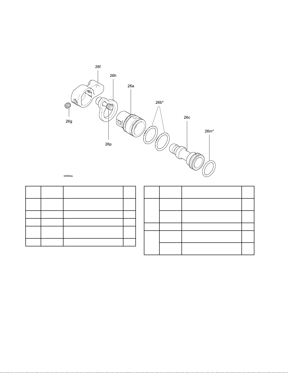
Parts
ES
On
Off
ES ES
On On
Part
No.
Part Part
No. No.
Part
No.
Part Part
No. No.
Valve
- --Off Off
Valve Valve
24N632
24N632 24N632
26A294
26A294 26A294
Assembly
Assembly Assembly
ES
On-Off
ES ES
On-Off On-Off
ES
On-Off
ES ES
On-Off On-Off
Valve
Assembly
Valve Valve
Assembly Assembly
Valve
with
Air
Valve Valve
with with
Restrictor
Air Air
Restrictor Restrictor
Assembly
Assembly Assembly
Part
No.
Ref.
Ref. Ref.
No.
No. No.
26a
26b*
26c
26f
26g
Part Part
———
15D371
———
24N650
GC2081SCREW,set,sockethead
Description
No. No.
Description Description
HOUSING,valve;blackfor
24N632,bluefor26A294
O-RING
PISTON,valve
LEVER,ESon-off;includes
26g
*ThesepartsareincludedinAirSealRepairKit
24N789(purchaseseparately).
Part
No.
Qty
Qty Qty
1
2
1
1
1
Ref.
Ref. Ref.
No.
No. No.
26h
26m*
26p
Part Part
24N631
16J578
113746
24N740
GC2081SCREW,captive;packof2;
Description
No. No.
Description Description
PLATE,retaining;forkit
24N632
PLATE,retaining;forkit
26A294
O-RING
SCREW,captive;packof2;
forkit24N632
forkit26A294
Qty
Qty Qty
1
1
1
1
Partslabeled———arenotavailableseparately.
583A2495K
Page 59

Parts
Fan
Air
Fan Fan
Part
Part Part
Adjustment
Air Air
Adjustment Adjustment
No.
24N634
No. No.
24N634 24N634
Fan
Fan Fan
Valve
Valve Valve
Air
Adjustment
Air Air
Adjustment Adjustment
Assembly
Assembly Assembly
Valve
Assembly
Valve Valve
Assembly Assembly
Ref.
Ref. Ref.
No.
No. No.
30a
30b
30c*
30d24N646
*ThesepartsareincludedinAirSealRepairKit
24N789(purchaseseparately).
Partslabeled———arenotavailableseparately.
Part
Part Part
———
———
111504
No.
Description
No. No.
Description Description
NUT,valve1
STEM,valve
O-RING
RING,retaining;packageof6
Qty
Qty Qty
1
1
1
3A2495K59
Page 60

Parts
Air
Cap
Air Air
Cap Cap
Part
No.
Part Part
No. No.
Ref.
Ref. Ref.
No.
No. No.
25a24N643
25b24N734
25c
25d24N726
27a183459
24N727
24N727 24N727
Part
Part Part
———
Assembly
Assembly Assembly
Air
Cap
Air Air
No.
Description
No. No.
Description Description
ELECTRODE;packageof5
O-RING;ptfe;packageof5
(alsoavailableinpackageof
10;order24E459)
AIRCAP
GUARD,tip,orange
GASKET,tip(notshown)
Assembly
Cap Cap
Assembly Assembly
Partslabeled———arenotavailableseparately.
Smart
Smart Smart
Part
Part Part
Qty
Qty Qty
1
1
1
1
5
Ref.
Ref. Ref.
No.
No. No.
31a
31b24P433
31c24N787
31d♦
31e♦
31f
Module
Module Module
No.
24N756
No. No.
24N756 24N756
Part
No.
Part Part
No. No.
———
———
———
112319
Assembly
Assembly Assembly
Smart
Smart Smart
Description
Description Description
CARTRIDGE
GASKET
SWITCH,ESHI/LO
SCREW
SCREW,pivot
O-RING
Module
Module Module
Assembly
Assembly Assembly
Qty
Qty Qty
1
1
1
3
1
1
Partslabeled———arenotavailableseparately.
♦ThesepartsareincludedinSmartModuleScrew
Kit24N757(purchaseseparately).
603A2495K
Page 61

SprayTipSelectionChart
Spray
Spray Spray
AEM
AEM AEM
Recommendedforhighnishqualityapplicationsatlowandmediumpressures.Orderdesiredtip,Part Part
AEMxxx,
AEMxxx, AEMxxx,
Orice
Orice Orice
Size
Size Size
in.
in. in.
(mm)
(mm) (mm)
0.007
(0.178)
0.009
(0.229)
0.011
(0.279)
0.013
(0.330)
0.015
(0.381)
0.017
(0.432)
0.019
(0.483)
0.021
(0.533)
0.023
(0.584)
0.025
(0.635)
0.029
(0.736)
0.031
(0.787)
0.033
(0.838)
0.037
(0.939)
0.039
(0.990)
*Tipsaretestedinwater.
Tip
Tip Tip
Fine
Fine Fine
wherexxx=3–digitnumberfromthematrixbelow.
Fluid
Fluid Fluid
oz/min
oz/min oz/min
at
600
at at
600 600
psi
psi psi
MPa,
MPa, MPa,
41
bar)
41 41
bar) bar)
4.0
(0.1)
7.0
(0.2)
10.0
(0.3)
13.0
(0.4)
17.0
(0.5)
22.0
(0.7)
28.0
(0.8)
35.0
(1.0)
40.0
(1.2)
50.0
(1.5)
68.0
(1.9)
78.0
(2.2)
88.0
(2.5)
108.0
(3.1)
118.0
(3.4)
Selection
Selection Selection
Finish
Finish Finish
(4.1
(4.1 (4.1
Spray
Spray Spray
Output
Output Output
(l/min)
(l/min) (l/min)
1000
at atat1000 1000
psi
(7.0
psi psi
(7.0 (7.0
MPa,
MPa, MPa,
70
bar)
70 70
bar) bar)
5.2
(0.15)
9.1
(0.27)
13.0
(0.4)
16.9
(0.5)
22.0
(0.7)
28.5
(0.85)
36.3
(1.09)
45.4
(1.36)
51.9
(1.56)
64.8
(1.94)
88.2
(2.65)
101.1
(3.03)
114.1
(3.42)
140.0
(4.20)
153.0
(4.59)
Tips
Tips Tips
2–4
2–4 2–4
(50–
(50– (50–
100)
100) 100)
107207307
Chart
Chart Chart
Maximum
Maximum Maximum
4–6
4–6 4–6
(100–
(100– (100–
150)
150) 150)
209309409509609
211311411511611711811
213313413513613713813
215315415515615715815
217317417517617717
Pattern
Pattern Pattern
8
6 66- --8 8
(150
-
(150 (150
- -
200)
200) 200)
319419519619719
Width
Width Width
in.
in. in.
10
8 88- --10 10
(200
(200 (200
250)
250) 250)
Spray
Spray Spray
421521621721821
423523623723823
425525625725825
431631831
at
12
in.
at at
12 12
(mm)
(mm) (mm)
10
12
10 10
- --12 12
-
(250
- -
-
(250 (250
- -
300)
300) 300)
Tip
Tip Tip
539
(305
in. in.
(305 (305
12
14
12 12
- --14 14
(300
(300 (300
350)
350) 350)
mm)
mm) mm)
14
14 14
-
(350
- -
(350 (350
400)
400) 400)
737
Part
No.
No. No.
16
16
- --16 16
-
- -
18
16 16
- --18 18
(400
-
(400 (400
- -
450)
450) 450)
829
833
Fluidoutput(Q)atotherpressures(P)canbecalculatedbythisformula:Q=(0.041)(QT) whereQT=
uidoutput(oz/min)at600psifromtheabovetablefortheselectedoricesize.
3A2495K61
Page 62

SprayTipSelectionChart
AEF
AEF AEF
Recommendedforhighnishqualityapplicationsatlowandmediumpressures.AEFtipshaveapre-orice
thatassistsinatomizingsheerthinningmaterials,includinglacquers.
Orderdesiredtip,Part Part
Fine
Fine Fine
Orice
Orice Orice
Size
Size Size
in.
(mm)
in. in.
(mm) (mm)
0.008
(0.203)
0.010
(0.254)
0.012
(0.305)
0.014
(0.356)
0.016
(0.406)
*Tipsaretestedinwater.
Finish
Finish Finish
Part
Fluid
Fluid Fluid
oz/min
oz/min oz/min
600
at atat600 600
(4.1
(4.1 (4.1
41
41 41
5.6(0.17)7.7(0.22)
9.5(0.28)
12.0
(0.35)
16.0
(0.47)
20.0
(0.59)
psi
psi psi
MPa,
MPa, MPa,
bar)
bar) bar)
Pre
Orice
Pre Pre
- --Orice Orice
No.
AEFxxx,
No. No.
AEFxxx, AEFxxx,
Output
Output Output
(l/min)
(l/min) (l/min)
at
1000
at at
1000 1000
psi
(7.0
psi psi
(7.0 (7.0
MPa,
70
MPa, MPa,
70 70
bar)
bar) bar)
12.5
(0.37)
16.0
(0.47)
21.0
(0.62)
26.5
(0.78)
Spray
Spray Spray
wherexxx=3–digitnumberfromthematrixbelow.
(150
6 66- --8 88(150 (150
200)
200) 200)
310410510610710810
312412512612712812
314414514614714814
Tips
Tips Tips
Maximum
Maximum Maximum
-
- -
8 88- --10 10
(200
(200 (200
416516616716
Pattern
Pattern Pattern
10
250)
- --250) 250)
Width
Width Width
in.
in. in.
10
12
10 10
- --12 12
(250
300)
(250 (250
- --300) 300)
Spray
Spray Spray
at
12
in.
at at
12 12
in. in.
(mm)
(mm) (mm)
12
14
12 12
- --14 14
(300
350)
(300 (300
- --350) 350)
Tip
Tip Tip
608
(305
mm)
(305 (305
mm) mm)
14
16
14 14
- --16 16
(350
400)
(350 (350
- --400) 400)
16
18
16 16
- --18 18
(400
450)
(400 (400
- --450) 450)
Fluidoutput(Q)atotherpressures(P)canbecalculatedbythisformula:Q=(0.041)(QT) whereQT=
uidoutput(oz/min)at600psifromtheabovetablefortheselectedoricesize.
623A2495K
Page 63

SprayTipSelectionChart
Round
Round Round
Toconverttheguntoaroundspraypattern,use
roundsprayconversionkit24N391.Seemanual
3A2499.
Part
Part Part
2368364A
2368376A
2368387A
2368395B
2368407B
2368419B
23684211B
*Flowsarebasedonwhiteacrylic,enamelpaint.
Spray
Spray Spray
No.
No. No.
Tips
Tips Tips
Size
No.
Size Size
No. No.
300
300 300
11.8oz/min(350cc/min)16.2oz/min(480cc/min)23.7oz/min(700cc/min)
Approximate
Approximate Approximate
psi
(2.1
psi psi
(2.1 (2.1
2.5oz/min(73cc/min)4.1oz/min(120cc/min)5.7oz/min(170cc/min)
2.9oz/min(86cc/min)5.1oz/min(150cc/min)7.4oz/min(220cc/min)
3.2oz/min(95cc/min)5.4oz/min(160cc/min)7.8oz/min(230cc/min)
5.4oz/min(160cc/min)7.8oz/min(230cc/min)11.0oz/min(330cc/min)
7.1oz/min(210cc/min)9.1oz/min(270cc/min)14.2oz/min(420cc/min)
8.8oz/min(260cc/min)11.8oz/min(350cc/min)17.9oz/min(530cc/min)
Flow
Rates
for
Light
to
Flow Flow
Rates Rates
for for
Light Light
(20–40
(20–40 (20–40
MPa,
21
bar)
MPa, MPa,
21 21
600
bar) bar)
600 600
centipoise)*
centipoise)* centipoise)*
psi
(4.2
psi psi
(4.2 (4.2
Medium
to to
Medium Medium
MPa,
42
MPa, MPa,
42 42
Viscosity
Viscosity Viscosity
bar)
bar) bar)
Coatings
Coatings Coatings
1200
psi
(8.4
1200 1200
psi psi
84
84 84
MPa,
(8.4 (8.4
MPa, MPa,
bar)
bar) bar)
3A2495K63
Page 64

SprayTipSelectionChart
Recommended
Recommended Recommended
Filter
Filter Filter
200mesh25N890
150mesh25N889
100mesh238562
60mesh238564
Filter
Filter Filter
Filter
Size
Size Size
Part
Filter Filter
Part Part
No.
No. No.
Sizes
Sizes Sizes
Round
Orice
Orice Orice
0.007(0.178)
0.009(0.229)
0.011(0.279)
0.011(0.279)
0.013(0.330)
0.013(0.330)
0.015(0.381)
0.017(0.432)
0.019(0.483)
0.021(0.533)
0.023(0.584)
0.025(0.635)
0.023(0.584)
0.025(0.635)
0.029(0.736)
0.031(0.787)
0.033(0.838)
0.037(0.939)
0.039(0.990)
Size
Size Size
in.
(mm)
in. in.
(mm) (mm)
Round Round
Filter
Filter Filter
200mesh25N890
150mesh25N889
100mesh238562
Spray
Spray Spray
Size
Size Size
Tips
Tips Tips
Filter
Part
Filter Filter
Part Part
No.
No. No.
Tip
Part
Tip Tip
Part Part
No.
No. No.
2368364A
2368376A
2368376A
2368387A
2368395B
2368407B
2368419B
23684211B
Tip
Size
Tip Tip
No.
Size Size
No. No.
643A2495K
Page 65

RepairKitsandAccessories
Repair
Repair Repair
Repair
Repair Repair
24N789
24N706AlternatorBearingRepairKit
Gun
Gun Gun
General
General General
Round
Round Round
Trigger
Trigger Trigger
Fan
Fan Fan
Accessories
Accessories Accessories
Part
No.
Part Part
No. No.
105749
111265
116553
24N603
24N604
24N758
Spray
Spray Spray
Part
No.
Part Part
No. No.
24N319
and
and and
Part
No.
Part Part
No. No.
24N520
24N521
24N633
24P170MetalTriggerKit
Valve
Valve Valve
Part
No.
Part Part
No. No.
24N634
24P172
25N919
Kits
Kits Kits
Kits
Kits Kits
Accessories
Accessories Accessories
Description
Description Description
CleaningBrush.
Non-siliconeLubricant,4oz(113g).
DielectricGrease.1oz(30ml)
GunCovers.For40kVand60kVguns.
Boxof10.
GunCovers.For85kVguns.Boxof10.
DisplayCovers.KeepsSmartdisplay
clean.Packageof5.
Accessories
Accessories Accessories
Description
Description Description
RoundSprayKit.Toconvertastandard
air—assistedsprayguntoaround
sprayaircap.Seemanual3A2499.
Grip
Grip Grip
Description
Description Description
ComfortGrip.Snap-ongripincreases
handlesizetoreduceoperatorfatigue.
Mediumsize.
ComfortGrip.Snap-ongripincreases
handlesizetoreduceoperatorfatigue.
Largesize.
PlasticTriggerKit(includedingun
models)
Accessories
Accessories Accessories
Description
Description Description
FanValve(includedingunmodels)
QuickAdjustFanValveforquickchange
offansize
QuickAdjustFanValvewithspring
return
and
and and
Repair
Repair Repair
AirSealRepairKit
Accessories
Accessories Accessories
Accessories
Accessories Accessories
Kit
Description
Kit Kit
Description Description
Adapter
Adapter Adapter
Part
Part Part
112534
185105
185493
24N642
224754
ES
ES ES
Part
Part Part
24N632
26A294
24P635
Inline
Inline Inline
60mesh
100mesh
150mesh
200mesh
and
Fitting
and and
No.
Description
No. No.
Description Description
AirLineQuickDisconnectFitting
Non-swivelAirInlet;1/4–18npsm(m)
(left-handthread)
AirHoseAdapter;1/4npt(m)x1/4–18
npsm(m)(left-handthread)
BallSwivel,forgunairinlet.1/4npsm
(left-handthread)
Valve,ball1/4npsm(left-handthread)
On/Off
On/Off On/Off
Filter
Filter Filter
Valve
Valve Valve
No.
Description
No. No.
Description Description
ESOn-OffValve(includedinH60M10,
H60T10,H85M10,H85T10)
ESOn/OffValvewithAirRestrictor
forhighatomizationairapplications.
Usethisaccessoryiftheturbinelight
indicatorisredandyouwanttomaintain
ahigherapplicationairpressure.Install
thekit,thenadjustthepressureas
neededtoensuretheindicatorremains
green.
ESAlwaysONvalve.Whenthisvalve
isinstalled,theelectrostaticsareon
anytimeairpressureissuppliedtothe
gun.Fluidadjustmentispossible.Use
with224754ballvalveinstalledatthe
gunairinlet.
Fluid
Fluid Fluid
Size
Size Size
Accessories
Fitting Fitting
Accessories Accessories
Accessories
Accessories Accessories
Filter
Filter Filter
224453
2385633
2385641
2385613
238562(includedingun
models)
25N8911
25N8923
25N8931
25N8943
Kit
Accessories
Kit Kit
Accessories Accessories
Filter
Kit
Filter Filter
Part
Kit Kit
Part Part
No.
No. No.
Qty.
Qty. Qty.
5
1
3A2495K65
Page 66

RepairKitsandAccessories
Operator
Operator Operator
Part
No.
Part Part
No. No.
117823
117824
117825
System
System System
Part
No.
Part Part
No. No.
222011
24N528
24P312
Accessories
Accessories Accessories
Description
Description Description
ConductiveGloves,boxof12(small)
ConductiveGloves,boxof12
(medium)
ConductiveGloves,boxof12(large)
Accessories
Accessories Accessories
Description
Description Description
GroundWireandClamp
GunFlushBoxAdapter.Toconvert
existinggunushboxestoholdProXp
guns.Seemanual309227.
GunWasherKit.Toconvertexisting
gunwasherstocleanProXpguns.See
manual308393.
Signs
Signs Signs
Part
No.
Part Part
No. No.
16P802
16P798
16P799
Test
Test Test
Equipment
Equipment Equipment
Part
Part Part
No.
No. No.
241079Megohmmeter.500Voutput,0.01–2000
722886
722860
Description
Description Description
EnglishWarningSign,availableat
nochargefromGraco
EnglishDailyCareSign
EnglishSetupSign
Description
Description Description
megohms.Useforgroundcontinuity
andgunresistancetests.Not Not
hazardous
hazardous hazardous
PaintResistanceMeter.Useforuid
resistivitytest.Seemanual307263.Not Not
for
use
for for
use use
PaintProbe.Useforuidresistivitytest.
Seemanual307263.Not Not
hazardous
hazardous hazardous
locations.
locations. locations.
hazardous
in ininhazardous hazardous
locations.
locations. locations.
Not
for
use
for for
locations.
locations. locations.
Not
for
use
for for
use use
in
use use
in in
Not
in
in in
245277TestFixture,HighVoltageProbe,and
kVMeter.Usetotesttheelectrostatic
voltageofthegun,andtheconditionof
thealternatorandpowersupplywhen
beingserviced.Seemanual309455.
663A2495K
Page 67

RepairKitsandAccessories
Hoses
Hoses Hoses
Grounded
Grounded Grounded
Air
Hoses
Air Air
Hoses Hoses
100psi(0.7MPa,7bar)MaximumWorkingPressure
0.315in.(8mm)ID;1/4npsm(f)x1/4npsm(f)
left-handthread
Part
No.
Part Part
No. No.
AirFlex
AirFlex AirFlex
244963
244964
244965
24J138
24N736
244966
24N737
244967
24N738
244968
244969
Part
Part Part
Standard
Standard Standard
223068
223069
223070
223071
223072
223073
223074
0.375
0.375 0.375
left
left left
Flexible
Flexible Flexible
No.
No. No.
Grounded
Grounded Grounded
in.
(10
in. in.
(10 (10
hand
thread
- --hand hand
thread thread
Description
Description Description
Grounded
Grounded Grounded
6ft(1.8m)
15ft(4.6m)
25ft(7.6m)
31ft(9.4m)
25ft(7.6m),with112534Quick
Disconnect
36ft(11m)
36ft(11m),with112534Quick
Disconnect
50ft(15m)
50ft(15m),with112534Quick
Disconnect
75ft(23m)
100ft(30.5m)
Description
Description Description
6ft(1.8m)
15ft(4.6m)
25ft(7.6m)
36ft(11m)
50ft(15m)
75ft(23m)
100ft(30.5m)
mm)
ID;
mm) mm)
ID; ID;
Air
Air Air
Air
Hose
Air Air
Hose Hose
3/8
npsm(f)
3/8 3/8
npsm(f) npsm(f)
Hose
Hose Hose
(Gray)
(Gray) (Gray)
Part
No.
Part Part
No. No.
Grounded
Grounded Grounded
ground
ground ground
235068
235069
(Gray)
(Gray) (Gray)
235070
235071
235072
235073
235074
Air
Air Air
path
path path
Whip
Hoses
Whip Whip
Hoses Hoses
Air
Air Air
Hose
Hose Hose
(Red)
(Red) (Red)
Description
Description Description
with
with with
6ft(1.8m)
15ft(4.6m)
25ft(7.6m)
36ft(11m)
50ft(15m)
75ft(23m)
100ft(30.5m)
stainless
stainless stainless
steel
braid
steel steel
braid braid
100psi(0.7MPa,7bar)MaximumWorkingPressure
0.188in.(5mm)ID;1/4npsm(m)x1/4npsm(f)
left-handthread
Part
No.
Part Part
No. No.
Air
Whip
Air Air
path
path path
236130
236131
Fluid
Fluid Fluid
Hose
Whip Whip
Hose Hose
(Red)
(Red) (Red)
Hoses
Hoses Hoses
with
with with
Description
Description Description
stainless
stainless stainless
3ft(0.9m)
6ft(1.8m)
steel
braid
steel steel
ground
braid braid
ground ground
3300psi(22.7MPa,227bar)MaximumWorking
Pressure
1/4in.(6mm)ID;1/4npsm(fbe);nylon.
Part
No.
Part Part
No. No.
240793
240794
Fluid
Whip
Fluid Fluid
Hoses
Whip Whip
Hoses Hoses
Description
Description Description
25ft(7.6m)
50ft(15m)
3200psi(22MPa,220bar)MaximumWorking
Pressure
1/4
npsm(f)
x xx1/4 1/4
npsm(f) npsm(f)
1/8in.(3mm)ID;1/4npsm(f)x1/4npt(m);nylon.
Part
No.
Part Part
No. No.
Description
Description Description
24A225
24A226
50ft(15m)
75ft(23m)
236134
236135
3ft(0.9m)
6ft(1.8m)
3A2495K67
Page 68
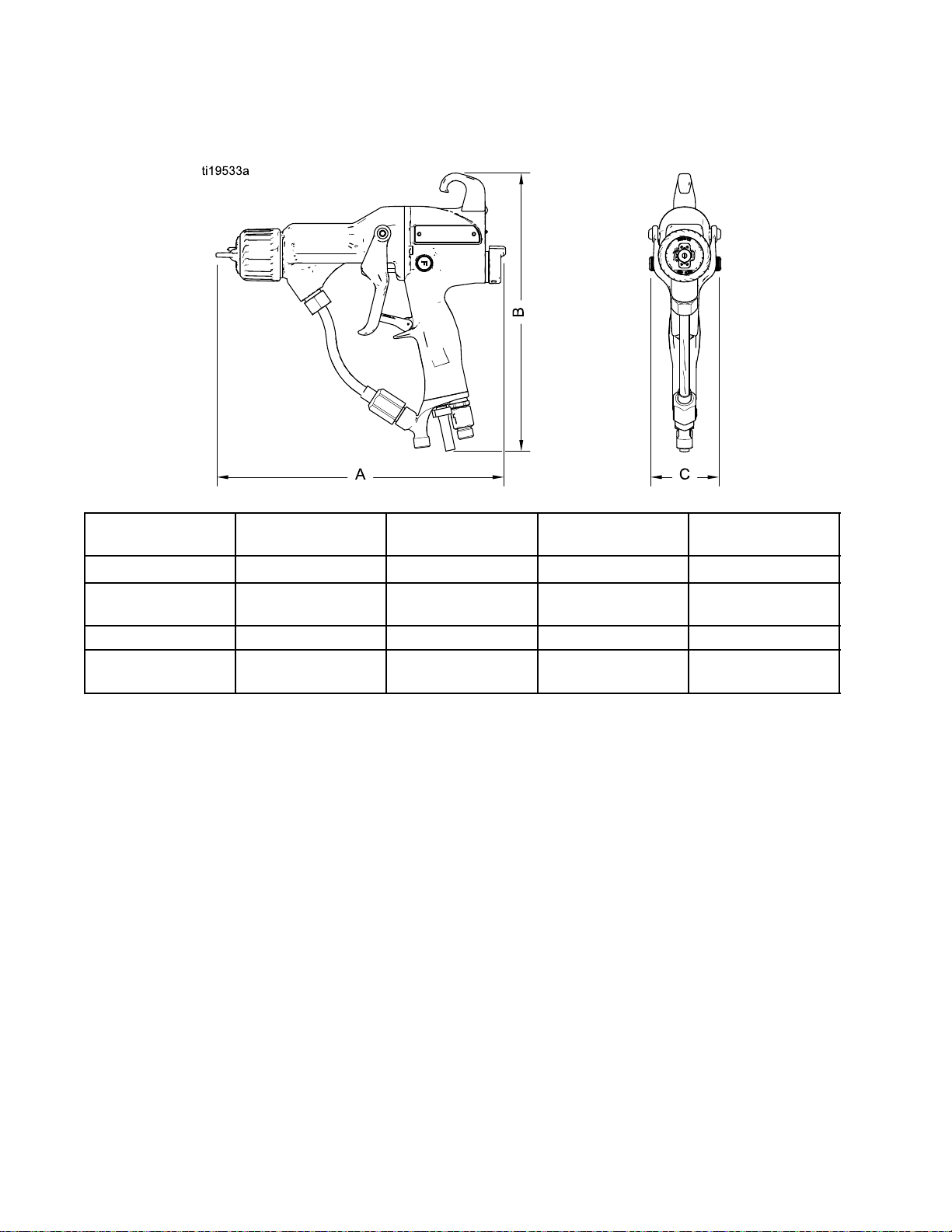
Dimensions
Dimensions
Dimensions Dimensions
Figure45
Gun
Gun Gun
H60T10
H85T10and
H85T57
H60M10
H85M10and
H85M57
Model
Model Model
A,
in.
(mm)
A, A,
in. in.
(mm) (mm)
9.7(246)9.1(231)2.4(61)23.2(659)
10.7(272)9.2(234)2.4(61)25.8(732)
9.8(249)9.9(251)2.4(61)25.7(728)
10.8(274)9.9(251)2.4(61)28.3(801)
B,
in.
(mm)
B, B,
in. in.
(mm) (mm)
C,
in.
(mm)
C, C,
in. in.
(mm) (mm)
Weight,
Weight, Weight,
oz
(g)
oz oz
(g) (g)
683A2495K
Page 69

TechnicalSpecications
Technical
Technical Technical
Electrostatic
Electrostatic Electrostatic
MaximumWorkingFluidPressure3000psi21MPa,210bar
MaximumWorkingAirPressure100psi0.7MPa,7.0bar
MinimumAirPressureatGunInlet
AirConsumption
Requiredturbineairow6scfm
Rangeoftotalairowunder
normalsprayingconditions
MaximumFluidOperating
Temperature
AmbientTemperature
PaintResistivityRange
AirInletFitting
FluidInletFitting
OutputVoltage
MaximumCurrentDraw
SoundPower(measuredperISO
Standard9216)
SoundPressure(measured1m
fromgun)
WettedPartsPEEK,UHMWPE,FEP,PTFE,acetal,nylon,polyethylene
Specications
Specications Specications
Air
Assisted
Air Air
- --Assisted Assisted
Spray
Guns
Spray Spray
Guns Guns
170l/min
220–400l/min
Metric
Metric Metric
U.S.
U.S. U.S.
45psi0.32MPa,3.2bar
7.5–14scfm
120°F48°C
41°–122°F5°–50°C
3megohm/cmtoinnity
1/4npsm(m)left-handthread
1/4–18npsm(m)
ProXp60Models:60kV
ProXp85Models:85kV
125microamperes
at40psi:88.9dB(A)
at100psi:99.7dB(A)
at40psi:86.0dB(A)
at100psi:95.0dB(A)
at0.28MPa,2.8bar:88.9dB(A)
at0.7MPa,7.0bar:99.7dB(A)
at0.28MPa,2.8bar:86.0dB(A)
at0.7MPa,7.0bar:95.0dB(A)
3A2495K69
Page 70

Graco
Graco Graco
GracowarrantsallequipmentreferencedinthisdocumentwhichismanufacturedbyGracoandbearingitsname
tobefreefromdefectsinmaterialandworkmanshiponthedateofsaletotheoriginalpurchaserforuse.Withthe
exceptionofanyspecial,extended,orlimitedwarrantypublishedbyGraco,Gracowill,foraperiodoftwelvemonths
fromthedateofsale,repairorreplaceanypartoftheequipmentdeterminedbyGracotobedefective.However,any
deciencyinthebarrel,handle,trigger,hook,internalpowersupply,andalternator(excludingturbinebearings)willbe
repairedorreplacedforthirty-sixmonthsfromthedateofsale.Thiswarrantyappliesonlywhentheequipmentis
installed,operatedandmaintainedinaccordancewithGraco’swrittenrecommendations.
Thiswarrantydoesnotcover,andGracoshallnotbeliableforgeneralwearandtear,oranymalfunction,damage
orwearcausedbyfaultyinstallation,misapplication,abrasion,corrosion,inadequateorimpropermaintenance,
negligence,accident,tampering,orsubstitutionofnon-Gracocomponentparts.NorshallGracobeliablefor
malfunction,damageorwearcausedbytheincompatibilityofGracoequipmentwithstructures,accessories,
equipmentormaterialsnotsuppliedbyGraco,ortheimproperdesign,manufacture,installation,operationor
maintenanceofstructures,accessories,equipmentormaterialsnotsuppliedbyGraco.
Thiswarrantyisconditionedupontheprepaidreturnoftheequipmentclaimedtobedefectivetoanauthorized
Gracodistributorforvericationoftheclaimeddefect.Iftheclaimeddefectisveried,Gracowillrepairorreplace
freeofchargeanydefectiveparts.Theequipmentwillbereturnedtotheoriginalpurchasertransportationprepaid.
Ifinspectionoftheequipmentdoesnotdiscloseanydefectinmaterialorworkmanship,repairswillbemadeata
reasonablecharge,whichchargesmayincludethecostsofparts,labor,andtransportation.
THIS
WARRANTY
THIS THIS
WARRANTY WARRANTY
INCLUDING
INCLUDING INCLUDING
PARTICULAR
PARTICULAR PARTICULAR
Graco’ssoleobligationandbuyer’ssoleremedyforanybreachofwarrantyshallbeassetforthabove.Thebuyer
agreesthatnootherremedy(including,butnotlimitedto,incidentalorconsequentialdamagesforlostprots,lost
sales,injurytopersonorproperty,oranyotherincidentalorconsequentialloss)shallbeavailable.Anyactionfor
breachofwarrantymustbebroughtwithintwo(2)yearsofthedateofsale.
GRACO
GRACO GRACO
FITNESS
FITNESS FITNESS
OR
OR OR
Graco(suchaselectricmotors,switches,hose,etc.),aresubjecttothewarranty,ifany,oftheirmanufacturer.Graco
willprovidepurchaserwithreasonableassistanceinmakinganyclaimforbreachofthesewarranties.
InnoeventwillGracobeliableforindirect,incidental,specialorconsequentialdamagesresultingfromGraco
supplyingequipmenthereunder,orthefurnishing,performance,oruseofanyproductsorothergoodssoldhereto,
whetherduetoabreachofcontract,breachofwarranty,thenegligenceofGraco,orotherwise.
FORGRACOCANADACUSTOMERS
ThePartiesacknowledgethattheyhaverequiredthatthepresentdocument,aswellasalldocuments,noticesand
legalproceedingsenteredinto,givenorinstitutedpursuantheretoorrelatingdirectlyorindirectlyhereto,bedrawn
upinEnglish.LespartiesreconnaissentavoirconvenuquelarédactionduprésentedocumentseraenAnglais,
ainsiquetousdocuments,avisetprocéduresjudiciairesexécutés,donnésouintentés,àlasuitedeouenrapport,
directementouindirectement,aveclesprocéduresconcernées.
MAKES
MAKES MAKES
FOR
FOR FOR
COMPONENTS
COMPONENTS COMPONENTS
Pro
Pro Pro
IS
IS IS
BUT
NOT
BUT BUT
NOT NOT
PURPOSE.
PURPOSE. PURPOSE.
NO
WARRANTY,
NO NO
WARRANTY, WARRANTY,
PARTICULAR
A AAPARTICULAR PARTICULAR
SOLD
SOLD SOLD
Xp
Xp Xp
EXCLUSIVE,
EXCLUSIVE, EXCLUSIVE,
LIMITED
LIMITED LIMITED
BUT
BUT BUT
Warranty
Warranty Warranty
AND
AND AND
TO
WARRANTY
TO TO
WARRANTY WARRANTY
AND
AND AND
PURPOSE,
PURPOSE, PURPOSE,
NOT
MANUFACTURED
NOT NOT
MANUFACTURED MANUFACTURED
LIEU
OF
ANY
IS ISISIN ININLIEU LIEU
DISCLAIMS
DISCLAIMS DISCLAIMS
IN
IN IN
OF OF
OF
MERCHANTABILITY
OF OF
MERCHANTABILITY MERCHANTABILITY
ALL
ALL ALL
CONNECTION
CONNECTION CONNECTION
OTHER
ANY ANY
OTHER OTHER
IMPLIED
IMPLIED IMPLIED
BY
GRACO.
BY BY
GRACO. GRACO.
WARRANTIES,
WARRANTIES, WARRANTIES,
OR
OR OR
WARRANTIES
WARRANTIES WARRANTIES
WITH
ACCESSORIES,
WITH WITH
ACCESSORIES, ACCESSORIES,
Theseitemssold,butnotmanufacturedby
EXPRESS
EXPRESS EXPRESS
WARRANTY
WARRANTY WARRANTY
OF
MERCHANTABILITY
OF OF
MERCHANTABILITY MERCHANTABILITY
EQUIPMENT,
EQUIPMENT, EQUIPMENT,
OR
IMPLIED,
OR OR
OF
OF OF
IMPLIED, IMPLIED,
FITNESS
FITNESS FITNESS
FOR
FOR FOR
AND
AND AND
MATERIALS
MATERIALS MATERIALS
A
A A
Graco
Graco Graco
For
For For
For
For For
To
To To
Phone:
Phone: Phone:
Allwrittenandvisualdatacontainedinthisdocumentreectsthelatestproductinformationavailableatthetimeofpublication.
the
latest
the the
latest latest
patent
patent patent
place
an
place place
an an
612-623-6921or ororToll Toll
Information
Information Information
information
information information
information,
information, information,
order,
order, order,
contactyourGracoDistributororcalltoidentifythenearestdistributor.
GRACO
GRACO GRACO
INC.
INC. INC.
Copyright
Copyright Copyright
about
about about
see
see see
Toll
Free:
Free: Free:
Gracoreservestherighttomakechangesatanytimewithoutnotice.
OriginalInstructions.ThismanualcontainsEnglish,MM3A2495
AND
SUBSIDIARIES
AND AND
SUBSIDIARIES SUBSIDIARIES
2012,
Graco
2012, 2012,
Graco Graco
Graco
Graco Graco
products,
products, products,
www.graco.com/patents.
1-800-328-0211Fax: Fax:
International
International International
Inc.
Inc. Inc.
Graco
Graco Graco
All
Graco
All All
Graco Graco
Fax:
Headquarters:
Headquarters: Headquarters:
Ofces:
Ofces: Ofces:
Belgium,China,Japan,Korea
P.O.
BOX
• ••P.O. P.O.
BOX BOX
manufacturing
manufacturing manufacturing
www.graco.com
RevisionK,2019–03
visit
visit visit
www.graco.com.
612-378-3505
Minneapolis
1441
1441 1441
• ••MINNEAPOLIS, MINNEAPOLIS,
MINNEAPOLIS,
locations
locations locations
MN
MN MN
are
registered
are are
registered registered
55440-1441
55440-1441 55440-1441
ISO
to totoISO ISO
USA
• ••USA USA
9001.
9001. 9001.
 Loading...