

Page 1
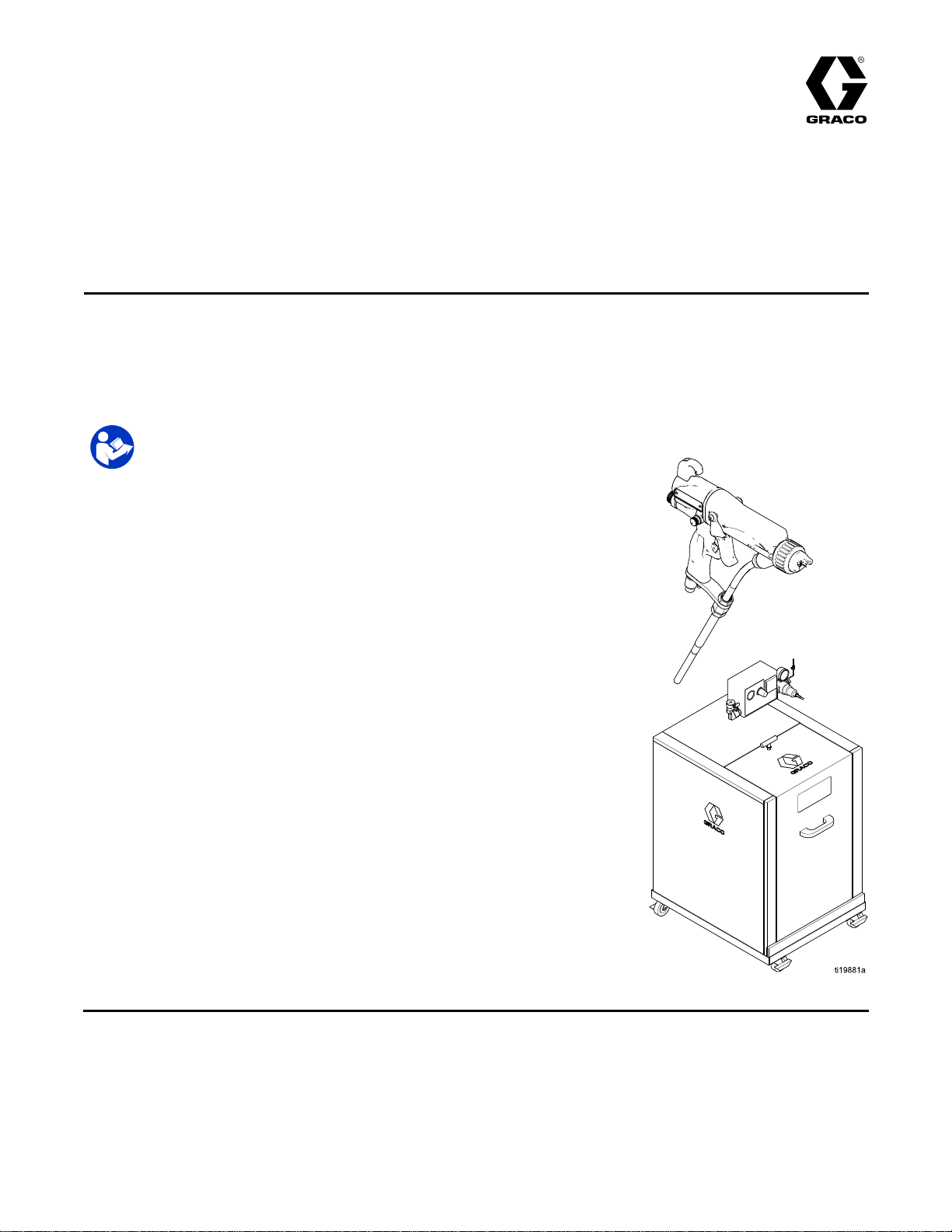
Instructions-Parts
WB100
WB100 WB100
Pro
Pro Pro
Air
Air Air
one
one one
For
For For
100psi(0.7MPa,7.0bar)Maximum
FluidWorkingPressure
100psi(0.7MPa,7.0bar)MaximumAir
WorkingPressure
Seepages3and4formodelpart
numbersandapprovalinformation.
Xp™
Xp™ Xp™
spray
spray spray
of
the
of of
the the
professional
professional professional
Important
Important Important
Readallwarningsandinstructionsinthismanual.Save Save
instructions.
instructions. instructions.
Isolation
Isolation Isolation
60
WB
60 60
WB WB
system
system system
conditions
conditions conditions
for
use
for for
use
use use
Safety
Safety Safety
when
use use
when when
for
non
for for
non non
- --ammability ammability
only.
only. only.
Instructions
Instructions Instructions
System
System System
Gun
Gun Gun
electrostatically
electrostatically electrostatically
ammability
and
and and
3A2496H
EN
spraying
spraying spraying
listed
on
listed listed
on on
conductive,
conductive, conductive,
page
3.
page page
3. 3.
Save
these
these these
waterborne
waterborne waterborne
uids
that
meet
at
uids uids
that that
meet meet
least
at at
least least
PROVENQUALITY.LEADINGTECHNOLOGY.
Page 2

Contents
Contents Contents
Models.................................................................3
RelatedManuals..................................................4
Warnings.............................................................5
GunOverview......................................................8
HowtheElectrostaticSprayGunWorks...........8
SprayingWaterborneFluids
Electrostatically................................8
Controls,Indicators,andComponents.............9
SmartGuns.................................................10
Installation..........................................................15
SystemRequirements..................................15
WarningSign...............................................15
InstalltheSystem.........................................15
VentilatetheSprayBooth.............................15
AirSupplyLine............................................16
GroundtheCabinet......................................16
ConnecttheWaterborneFluidHose..............17
Grounding...................................................22
AgitatorKitAccessory..................................24
FluidRegulatorKitAccessory.......................25
GunSetup..........................................................26
GunSetupProcedure...................................26
SoftSprayGunSetupProcedure..................30
HVLPGunSetupProcedure.........................31
RoundSprayGunSetupProcedure..............33
AbrasiveMaterialGunSetup
Procedure......................................35
MoldReleaseGunSetupProcedure.............36
CheckGunElectricalGrounding...................38
FlushBeforeUsingEquipment......................38
Operation...........................................................39
PressureReliefProcedure............................39
FluidVoltageDischargeandGrounding
Procedure......................................39
FilltheFluidSupply......................................40
Startup........................................................40
Shutdown....................................................41
Maintenance......................................................42
DailyCareandCleaningChecklist................42
Flushing......................................................42
CleantheGunDaily.....................................44
DailySystemCare.......................................46
ElectricalTests...................................................47
TestGunResistance....................................47
TestPowerSupplyResistance.....................48
TestElectrodeResistance............................49
TestGroundStripResistance.......................50
TestCylinderResistance..............................50
Troubleshooting..................................................51
VoltageLossTroubleshooting.......................51
SprayPatternTroubleshooting......................54
GunOperationTroubleshooting....................55
ElectricalTroubleshooting............................56
Repair................................................................58
PreparetheGunforService.........................58
AirCapandNozzleReplacement..................59
AirCap,SprayTip,andNozzle
Replacement(Model
L60M19)........................................60
ElectrodeReplacement................................61
NeedleReplacement(ModelL60M19)...........62
FluidPackingRodRemoval..........................62
PackingRodRepair.....................................63
BarrelRemoval............................................65
BarrelInstallation.........................................65
PowerSupplyRemovaland
Replacement..................................66
AlternatorRemovalandReplacement...........67
FanAirAdjustmentValveRepair..................69
AtomizingAirRestrictorValveRepair............70
ESOn-OffandFluidAdjustmentValve
Repair............................................71
AirValveRepair...........................................72
SmartModuleReplacement..........................73
AirSwivelandExhaustValve
Replacement..................................74
Parts..................................................................75
StandardWaterborneAirSprayGun
Assembly.......................................75
SmartWaterborneAirSprayGun
Assembly.......................................77
MoldReleaseSmartAirSprayGun
Assembly.......................................79
IsolationEnclosure.......................................81
TubingandWiring.......................................84
PackingRodAssembly.................................86
AlternatorAssembly.....................................87
ESOn-OffandFluidAdjustmentValve...........88
FanAirAdjustmentValveAssembly..............89
AtomizingAirRestrictorValve
Assembly.......................................89
AirCapAssembly........................................90
SmartModuleAssembly...............................90
RoundSprayAssembly................................91
FluidNozzles.....................................................93
FluidNozzleSelectionChart.........................93
FluidNozzlePerformanceCharts..................94
AirCaps.............................................................96
AirCapSelectionGuide...............................96
AirConsumptionCharts.............................101
SprayTipSelectionChart(ModelL60M19MRG
GunOnly)...........................................102
AEMFineFinishSprayTips........................102
AEFFineFinishPre-OriceSpray
Tips.............................................103
RoundSprayTips......................................104
RepairKitsandAccessories..............................105
Dimensions......................................................109
TechnicalSpecications....................................111
2
3A2496H
Page 3

Models
2575
Models
Models Models
FMapprovedforusewithuidsthatmeetthefollowingcondition:
•MaterialdoesnotsustainburninginaccordancewiththeStandardTest
MethodforSustainedBurningofLiquidMixtures,ASTMD4206.
0.35
0.35 0.35
Part
Part Part
24N580WB100WaterborneIsolationEnclosure233825withstandardelectrostaticairspraygun
24P629WB100WaterborneIsolationEnclosure233825withsmartelectrostaticairspraygun
24P630WB100WaterborneIsolationEnclosure246511withstandardelectrostaticairspraygun
24P631WB100WaterborneIsolationEnclosure246511withsmartelectrostaticairspraygun
233825WB100
24P734WB100
246511WB100
L60T17ProXp60
with
50
hose
J, J,J,with with
FM12ATEX0080
FM12ATEX0080 FM12ATEX0080
No
No No
50 50
ft ftfthose hose
EN
50059
EN EN
50059 50059
Ta
0°C
Ta Ta
50°C
0°C 0°C
– ––50°C 50°C
Model
Model Model
WB
max
max max
•Materialswhichcannotbeignited,inanymixturewithair,byanenergy
Description
Description Description
L60T17,groundedairhose235070,andshieldedwaterborneuidhose24M732.
L60M17,groundedairhose235070,andshieldedwaterborneuidhose24M732.
L60T18,groundedairhose235070,andunshieldedwaterborneuidhose24M733.
L60M18,groundedairhose235070,andunshieldedwaterborneuidhose24M733.
WaterborneIsolationEnclosureforshieldedhoses.Doesnotincludehosesandgun.
WaterborneIsolationEnclosure246511withMRGsmartelectrostaticairspraygun
L60M19,groundedairhose235070,andunshieldedwaterborneuidhose24M733.
WaterborneIsolationEnclosureforunshieldedhoses.Doesnotincludehoses
andgun.
StandardElectrostaticAirSprayGun,forwaterbornecoatings.
ModelsCompliantwithEN50059whenused
withuidsthatmeetthefollowingcriteria:
sourceoflessthan500mJ.
L60M17ProXp60
L60T18ProXp60
L60M18ProXp60
L60M19ProXp60
WBMRG
24M732
24M733
25N916
25N917
-——
-——
-——
-——
WB
WB
WB
SmartElectrostaticAirSprayGun,forwaterbornecoatings.
StandardElectrostaticAirSprayGun,forwaterbornecoatings.
SmartElectrostaticAirSprayGun,forwaterbornecoatings.
SmartElectrostaticAirSprayGun,formoldreleaseapplications.
ShieldedWaterborneFluidHoseAssembly,25ft(7.6m).
UnshieldedWaterborneFluidHoseAssembly,25ft(7.6m).
ShieldedWaterborneFluidHoseAssembly,50ft(15.2m).
UnshieldedWaterborneFluidHoseAssembly,50ft(15.2m).
3A2496H3
Page 4

RelatedManuals
Related
Related Related
Manual
Manual Manual
3A2498
307263ProbeandMeter,Instructions
309455TestFixture,HighVoltageProbe,andkVMeter,Instructions
406999
No.
No. No.
Manuals
Manuals Manuals
Description
Description Description
RoundSprayKit,Instructions
VoltageTesterConversionKit,Instructions
4
3A2496H
Page 5
Warnings
Warnings Warnings
Thefollowingwarningsareforthesetup,use,grounding,maintenance,andrepairofthisequipment.The
exclamationpointsymbolalertsyoutoageneralwarningandthehazardsymbolsrefertoprocedure-specic
risks.Whenthesesymbolsappearinthebodyofthismanualoronwarninglabels,referbacktothese
Warnings.Product-specichazardsymbolsandwarningsnotcoveredinthissectionmayappearthroughout
thebodyofthismanualwhereapplicable.
WARNING
WARNING WARNING
FIRE
AND
FIRE FIRE
Combustibledustinwork work
•Fluidsusedmustmeetthefollowingammabilityrequirements:
Stop
•Stop Stop
equipmentuntilyouidentifyandcorrecttheproblem.
•Checkgunresistance,hoseresistance,andelectricalgroundingdaily.
•Useandcleanequipmentonlyinwellventilatedarea.
•Interlockthegunairsupplytopreventoperationunlessventilationairowisabovethe
minimumrequiredvalue.
•Onlyusenon-ammablesolventswhenushingorcleaningequipment.
•Alwaysturntheelectrostaticsoffwhenushing,cleaningorservicingequipment.
•Eliminateallignitionsources;suchaspilotlights,cigarettes,portableelectriclamps,and
plasticdropcloths(potentialstaticarc).
•Donotplugorunplugpowercordsorturnlightsonoroffwhenammablefumesarepresent.
•Keepsprayareafreeofdebris,includingsolvent,ragsandgasoline.
•Keepaworkingreextinguisherintheworkarea.
EXPLOSION
AND AND
EXPLOSION EXPLOSION
FM,
FMc
•FM, FM,
MaterialdoesnotsustainburninginaccordancewiththeStandardTestMethodfor
SustainedBurningofLiquidMixtures,ASTMD4206.
CE
•CE CE
Materialswhichcannotbeignited,inanymixturewithair,byanenergysourceof
lessthan500mJ.
operation
operation operation
Approved:
FMc FMc
Approved: Approved:
EN
50059
- --EN EN
50059 50059
immediately
immediately immediately
HAZARD
HAZARD HAZARD
work
area
area area
canigniteorexplode.Tohelppreventreandexplosion:
Compliant:
Compliant: Compliant:
ifstaticsparkingoccursoryoufeelashock.Donotuse
Warnings
3A2496H5
Page 6
Warnings
WARNING
WARNING WARNING
ELECTRIC
ELECTRIC ELECTRIC
Impropergrounding,setup,orusageofanisolatedwaterbornesystemcanresultinelectric
shock.Tohelppreventelectricshock:
•Groundallequipment,personnel,objectbeingsprayed,andconductiveobjectsinorclose
tosprayarea.SeeGrounding Grounding
•Connecttheelectrostaticguntoavoltageisolationsystemthatwilldischargethesystem
voltagewhennotinuse.
•Allcomponentsoftheisolationsystemthatarechargedtohighvoltagemustbecontained
withinanisolationenclosurethatpreventspersonnelfrommakingcontactwiththehigh
voltagecomponentsbeforethesystemvoltageisdischarged.
•FollowtheFluid Fluid
thevoltage;beforecleaning,ushing,orservicingthesystem;beforeapproachingthefrontof
thegun;andbeforeopeningtheisolationenclosurefortheisolateduidsupply.
•Donotenterahighvoltageorhazardousareauntilallhighvoltageequipmenthasbeen
discharged.
•Donottouchthegunnozzleorelectrode,orcomewithin4in.(102mm)oftheelectrode
duringgunoperation.FollowtheFluid Fluid
•Interlockthegunairsupplywiththevoltageisolationsystemtoshutofftheairsupplyanytime
theisolationsystemenclosureisopened.
•Onlyusethered-coloredGracoelectricallyconductivegunairhosewiththisgun.Donot
useblackorgray-coloredGracoairhoses.
•Donotsplicehosestogether.InstallonlyonecontinuousGracowaterborneuidhose
betweentheisolateduidsupplyandthespraygun.
PRESSURIZED
PRESSURIZED PRESSURIZED
Fluidfromtheequipment,leaks,orrupturedcomponentscansplashintheeyesoronskin
andcauseseriousinjury.
SHOCK
SHOCK SHOCK
Fluid
HAZARD
HAZARD HAZARD
Grounding
Voltage
Voltage Voltage
EQUIPMENT
EQUIPMENT EQUIPMENT
instructions.
Discharge
Discharge Discharge
HAZARD
HAZARD HAZARD
and
Grounding
and and
Grounding Grounding
Fluid
Voltage
Voltage Voltage
Procedure
Procedure Procedure
Discharge
Discharge Discharge
and
and and
wheninstructedtodischarge
Grounding
Grounding Grounding
Procedure
Procedure Procedure
.
•FollowthePressure Pressure
cleaning,checking,orservicingequipment.
•Tightenalluidconnectionsbeforeoperatingtheequipment.
•Checkhoses,tubes,andcouplingsdaily.Replacewornordamagedpartsimmediately.
Pressure
Relief
Procedure
Relief Relief
Procedure Procedure
whenyoustopspraying/dispensingandbefore
63A2496H
Page 7

Warnings
WARNING
WARNING WARNING
EQUIPMENT
EQUIPMENT EQUIPMENT
Misusecancausedeathorseriousinjury.
•Donotoperatetheunitwhenfatiguedorundertheinuenceofdrugsoralcohol.
•Donotexceedthemaximumworkingpressureortemperatureratingofthelowestrated
systemcomponent.SeeTechnical Technical
•Useuidsandsolventsthatarecompatiblewithequipmentwettedparts..SeeTechnical Technical
Specications
Specications Specications
Forcompleteinformationaboutyourmaterial,requestaSafetyDataSheet(SDS)from
yourdistributororretailer.
•Donotleavetheworkareawhileequipmentisenergizedorunderpressure.
•TurnoffallequipmentandfollowthePressure Pressure
•Checkequipmentdaily.Repairorreplacewornordamagedpartsimmediatelywithgenuine
manufacturer’sreplacementpartsonly.
•Donotalterormodifyequipment.Alterationsormodicationsmayvoidagencyapprovals
andcreatesafetyhazards.
•Makesureallequipmentisratedandapprovedfortheenvironmentinwhichyouareusingit.
•Useequipmentonlyforitsintendedpurpose.Callyourdistributorforinformation.
•Routehosesandcablesawayfromtrafcareas,sharpedges,movingparts,andhotsurfaces.
•Donotkinkoroverbendhosesorusehosestopullequipment.
•Keepchildrenandanimalsawayfromworkarea.
•Complywithallapplicablesafetyregulations.
PLASTIC
PLASTIC PLASTIC
Manysolventscandegradeplasticpartsandcausethemtofail,whichcouldcauseserious
injuryorpropertydamage.
MISUSE
MISUSE MISUSE
PARTS
PARTS PARTS
HAZARD
HAZARD HAZARD
Technical
inallequipmentmanuals.Readuidandsolventmanufacturer’swarnings.
CLEANING
CLEANING CLEANING
SOLVENT
SOLVENT SOLVENT
Specications
Specications Specications
Pressure
HAZARD
HAZARD HAZARD
Relief
Relief Relief
inallequipmentmanuals.
Procedure
Procedure Procedure
whenequipmentisnotinuse.
Technical
•Useonlycompatiblewater-basedsolventstocleanplasticstructuralorpressure-containing
parts.
•SeeTechnical Technical
TOXIC
TOXIC TOXIC
Toxicuidsorfumescancauseseriousinjuryordeathifsplashedintheeyesoronskin,
inhaled,orswallowed.
•ReadSafetyDataSheet(SDS)toknowthespecichazardsoftheuidsyouareusing.
•Storehazardousuidinapprovedcontainers,anddisposeofitaccordingtoapplicable
PERSONAL
PERSONAL PERSONAL
Wearappropriateprotectiveequipmentwhenintheworkareatohelppreventseriousinjury,
includingeyeinjury,hearingloss,inhalationoftoxicfumes,andburns.Thisprotective
equipmentincludesbutisnotlimitedto:
•Protectiveeyewear,andhearingprotection.
•Respirators,protectiveclothing,andglovesasrecommendedbytheuidandsolvent
Technical
thesolventmanufacturerforinformationandrecommendationsaboutcompatibility.
FLUID
FLUID FLUID
guidelines.
manufacturer.
Specications
Specications Specications
OR
FUMES
OR OR
FUMES FUMES
PROTECTIVE
PROTECTIVE PROTECTIVE
inallequipmentmanualsformaterialsofconstruction.Consult
EQUIPMENT
EQUIPMENT EQUIPMENT
3A2496H
7
Page 8

GunOverview
Gun
Gun Gun
How
How How
Works
Works Works
Theairhosesuppliesairtothespraygun.Partofthe
airoperatesthealternatorturbineandtherestofthe
airatomizestheuidbeingsprayed.
Thealternatorgeneratespower,whichisconverted
bythepowercartridgetosupplyhighvoltagetothe
gun’selectrode.
Thepumpsuppliesuidtotheuidhoseandgun,
wheretheuidiselectrostaticallychargedasit
passestheelectrode.Thechargeduidisattracted
tothegroundedworkpiece,wrappingaroundand
evenlycoatingallsurfaces.
Spraying
Spraying Spraying
Electrostatically
Electrostatically Electrostatically
Thiselectrostaticairspraygunisdesignedtospray
only
only only
ammabilityrequirements:
Overview
Overview Overview
the
Electrostatic
the the
Electrostatic Electrostatic
Waterborne
Waterborne Waterborne
waterborneuidswhichmeetthefollowing
Spray
Spray Spray
Fluids
Fluids Fluids
Gun
Gun Gun
CE-EN
•CE-EN CE-EN
Materialswhichcannotbeignited,inanymixture
withair,byanenergysourceoflessthan500mJ.
Whenconnectedtoavoltageisolationsystem,
alloftheuidinthespraygun,uidhose,and
isolateduidsupplyischargedtohighvoltage,
whichmeansthatthesystemhasmoreelectrical
energythanasolvent-basedsystem.Therefore,
onlynon-ammableuids(asdenedunder
Models,page3)canbesprayedwiththesystemor
beusedtoclean,ush,orpurgethesystem.
Precautionsmustbetakenwhenusingelectrostatic
waterborneequipmenttoavoidpotentialshock
hazards.Whenthespraygunchargestheisolated
uidtohighvoltage,itissimilartocharginga
capacitororabattery.Thesystemwillstoresomeof
theenergywhilesprayingandretainsomeofthat
energyafterthespraygunisshutoff.Donottouch
thegunnozzleorcomewithin4in.(102mm)of
theelectrodeuntilthestoredenergyisdischarged.
Theamountoftimeittakestodischargethe
energydependsonthesystemdesign.Followthe
FluidVoltageDischargeandGroundingProcedure,
page39,beforeapproachingthefrontofthegun.
50059
50059 50059
Compliant:
Compliant: Compliant:
FM,
FMc
•FM, FM,
Materialdoesnotsustainburninginaccordance
withtheStandardTestMethodforSustained
BurningofLiquidMixtures,ASTMD4206.
Approved:
FMc FMc
Approved: Approved:
NOTE:
NOTE: NOTE:
voidiftheelectrostaticspraygunisconnectedtoa
non-Gracovoltageisolationsystemorifthegunis
operatedabove60kV.
TheGracowarrantyandapprovalsare
83A2496H
Page 9
GunOverview
Controls,
Controls, Controls,
Theelectrostaticgunincludesthefollowingcontrols,indicators,andcomponents.ForinformationonSmart
guns,alsoseeSmartGuns,page10.
Figure1GunOverview
Item
Item Item
Indicators,
Indicators, Indicators,
Description
Description Description
and
Components
and and
Components Components
Purpose
Purpose Purpose
A
BFluidInlet
C
D
EElectrodeNeedle
FFanAirAdjustmentValve
G
HFluidAdjustmentKnob
J
K
AirSwivelInlet1/4npsm(m)left-handthread,forGracored-coloredgroundedair
TurbineAirExhaust
AirCapandNozzleSeeAirCaps,page96andFluidNozzles,page93foravailable
AtomizingAirRestrictor
Valve
ESOn-OffValveTurnselectrostaticsON(I)orOFF(O).
ESIndicator(standard
gunonly;forSmart
gunindicator,see
OperatingMode,page10)
supplyhose.
Gracowaterborneuidsupplyhose
Barbedtting,forsuppliedexhausttube.
sizes.
Supplieselectrostaticchargetotheuid.
Adjustsfansizeandshape.Canbeusedtodecreasepatternwidth.
Restrictsaircapairow.Replacewithplug(included)ifdesired.
Adjustsuidowbylimitinguidneedletravel.Useonlyinlowow
conditions,toreducewear.
LitwhenESisON(I).Colorindicatesalternatorfrequency.Seethe
LEDindicatortableonpage36.
3A2496H9
Page 10
GunOverview
Smart
Smart Smart
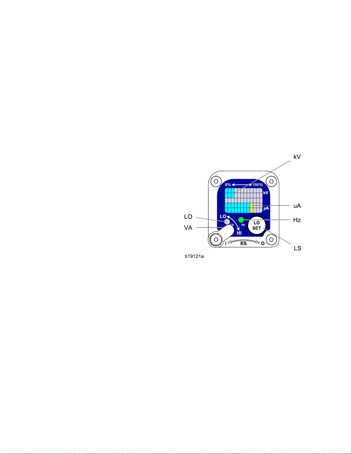
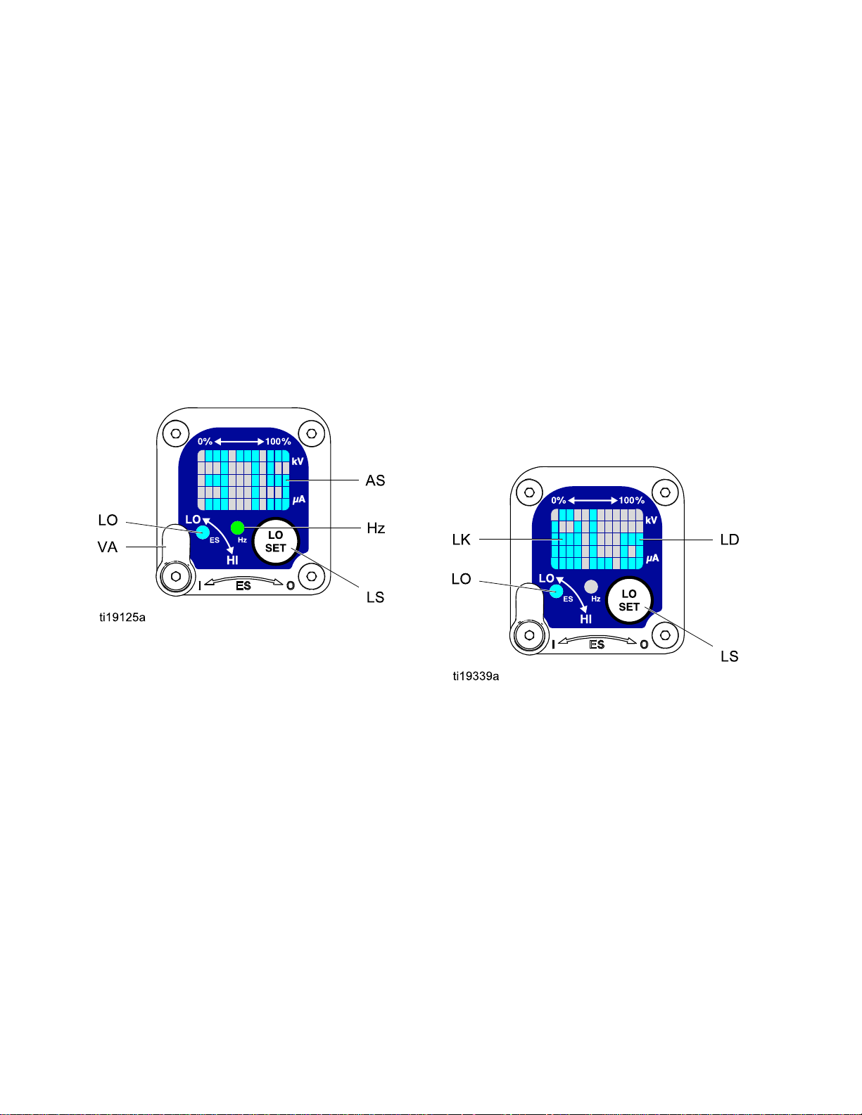
TheSmartGunmoduledisplayssprayingvoltage,
current,alternatorspeed,andthevoltagesetting(low
orhigh).Italsoallowstheusertochangetoalower
sprayingvoltage.Themodulehastwomodes:
•OperatingMode
•DiagnosticMode
Operating
Operating Operating
Bar
Bar Bar
SeeFig.2andSmartGunKey,page12.The
OperatingModedisplaysgundataduringnormal
spraying.Thedisplayusesabargraphtoshowthe
voltagelevelinkiloVolts(kV)andthecurrentlevelin
microAmperes(uA).Thebargraphrangeisfrom0
to100%foreachvalue.
IfthebargraphLEDsareblue,thegunisreadyto
spray.IftheLEDsareyelloworred,thecurrentis
toohigh.Theuidmaybetooconductive,orsee
ElectricalTroubleshooting,page56forotherpossible
causes.
Guns
Guns Guns
Mode
Mode Mode
Graph
Graph Graph
Voltage
Voltage Voltage
Thevoltageadjustmentswitch(VA)allowsthe
operatortochangefromlowtohighvoltage.
•Thehighvoltagesettingisdeterminedbythe
maximumvoltageofthegunandisnotadjustable.
•Thelowvoltageindicator(LO)lights
whentheswitchissettoLO.Thelow
voltagesettingisuseradjustable.See
AdjustingtheLowVoltageSetting,page11.
NOTE:
NOTE: NOTE:
haslostcommunicationwiththepowersupply.See
ErrorDisplay,page11forfurtherinformation.
Adjustment
Adjustment Adjustment
IftheErrordisplayappears,theSmartmodule
Switch
Switch Switch
Hz
Indicator
Hz Hz
Indicator Indicator
TheHzindicatorfunctionsthesameastheES
indicatoronstandardguns.Theindicatorlightsto
showthealternatorspeedstatus,andhasthree
colors:
•Greenindicatesthealternatorspeediscorrect.
•Iftheindicatorchangestoamberafteronesecond,
increasetheairpressure.
•Iftheindicatorchangestoredafteronesecond,
theairpressureistoohigh.Decreaseairpressure
untiltheindicatorisgreen.Tomaintainahigher
airpressure,installESOn/OffValveRestrictorKit
26A160.Then,adjustthepressureasneededto
ensuretoensuretheindicatorremainsgreen.
Figure2SmartGunModuleinOperatingMode
103A2496H
Page 11
GunOverview
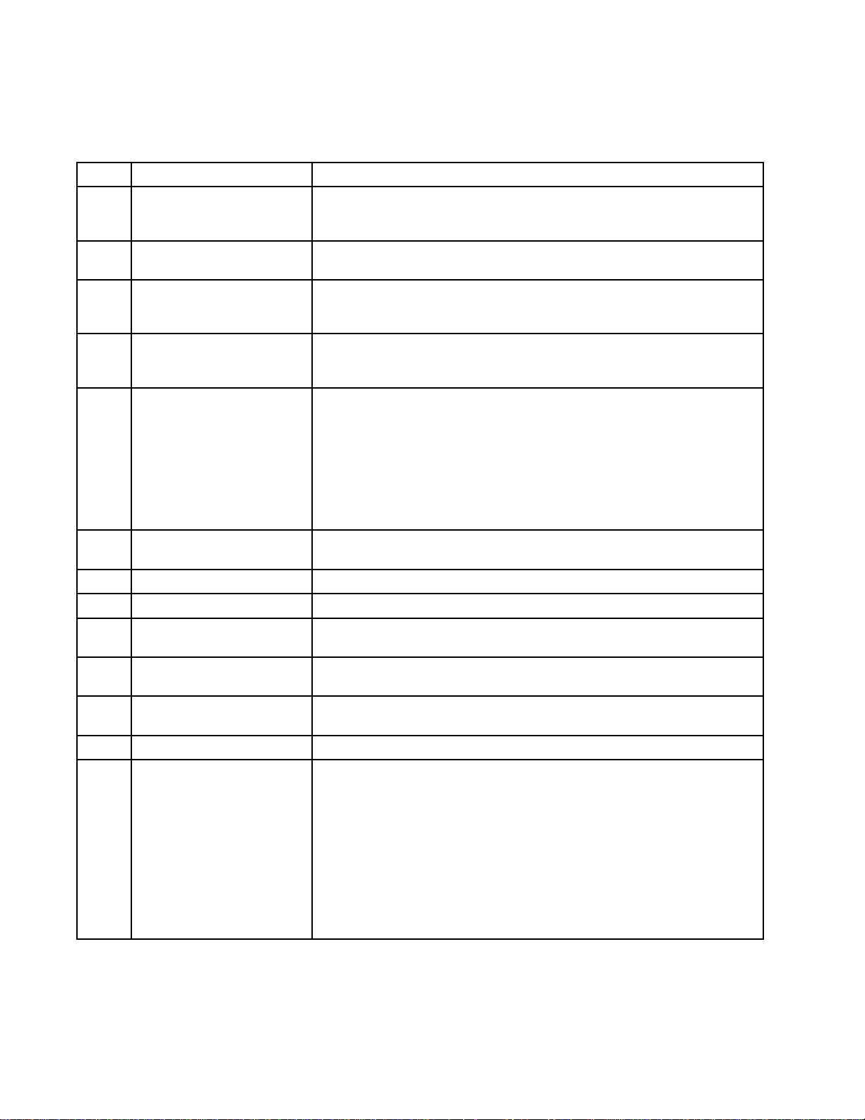
Error
Error Error
IftheSmartmodulelosescommunicationwith
thepowersupply,theErrordisplayappears,the
Hzindicatorturnsred,andtheSmartmoduleis
disabled.SeeFig.3andSmartGunKey,page12.
ThiscanoccurinOperatingModeorDiagnostic
Mode.SeeElectricalTroubleshooting,page56.
CommunicationmustberestoredtomaketheSmart
modulefunctional.
NOTE:
NOTE: NOTE:
appear.Ifthegunhasbeendisassembled,wait8
secondsbeforesprayingtoensurethatanError
conditionhasnotoccurred.
NOTE:
NOTE: NOTE:
displaywillnotappear.
Display
Display Display
Ittakes8secondsfortheErrordisplayto
Ifthereisnopowertothegun,theError
NOTE:
NOTE: NOTE:
returntotheOperatingScreen.
NOTE:
NOTE: NOTE:
LockSymbol,page11.
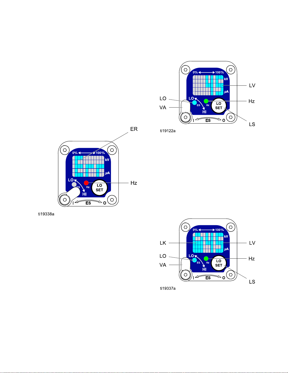
Figure4LowVoltageSettingScreen(Unlocked)
Lock
Lock Lock
Thelowvoltagesettingmaybelocked.Whenlocked,
animage(LK)appearsonthescreen.SeeFig.5
andSmartGunKey,page12.
After2secondsofinactivitythedisplaywill
Thelowvoltagesettingmaybelocked.See
Symbol
Symbol Symbol
Figure3ErrorDisplay
Adjusting
Adjusting Adjusting
Thelowvoltagesettingisuseradjustable.Toaccess
thelowvoltagesettingscreenwheninOperating
Mode,presstheLOSETbutton(LS)momentarily.
Thescreenwilldisplaythecurrentlowvoltage
setting.SeeFig.4andSmartGunKey,page12.
Therangeis30–60kV.
SettheVoltageAdjustmentswitch(VA)toLO.Press
theLOSETbuttonrepeatedlytoincreasethesetting
inincrementsof5.Whenthedisplayreachesthe
maximumsetting(60kV)itwillreturntotheminimum
setting(30kV).Continuepressingthebuttonuntil
youreachthedesiredsetting.
the
Low
the the
Voltage
Low Low
Voltage Voltage
Setting
Setting Setting
•WheninHImode,thelowvoltagesettingisalways always
locked.ThelocksymbolwillappearwhentheLO
SETbuttonispressed.
•WheninLOmode,thelocksymbolwill
only
only only
appearifthelockisenabled.See
LowVoltageLockScreen,page14,tolockor
unlockthelowvoltagesetting.
Figure5LowVoltageSettingScreen(Locked)
always
3A2496H
11
Page 12
GunOverview
Smart
Smart Smart
Table
Table Table
Item
Item Item
VA
LO
kV
uA
LSLOSETbuttonPressmomentarilytoentertheLowVoltageSettingscreen.
Gun
Key
Gun Gun
Key Key
Key
for
Figs.
1 11Key Key
for for
Description
Description Description
VoltageAdjustmentSwitchTwo-positionswitchsetsSmartgunvoltagetolowsetting(LO)or
LowVoltageMode
Indicator
Voltage(kV)DisplayDisplaysactualsprayingvoltageofthegun,inkV.InOperatingMode,
Current(uA)DisplayDisplaysactualsprayingcurrentofthegun,inuA.InOperatingMode,
2–9.
Figs. Figs.
2–9. 2–9.
Purpose
Purpose Purpose
highsetting(HI).ThisswitchisfunctionalinOperatingModeandin
DiagnosticMode.
Lights(blue)whentheSmartgunissettoLowVoltage.
displayisabargraph.InDiagnosticMode,voltageisdisplayedas
anumber.
displayisabargraph.InDiagnosticMode,currentisdisplayedas
anumber.
Pressandholdforapproximately5secondstoenterorexitDiagnostic
Mode.
WhileinDiagnosticMode,pressmomentarilytoadvancethrough
screens.
WhileontheLowVoltageLockScreen(inDiagnosticMode),press
andholdtoturnthelockonoroff.
LVLowVoltageDisplayDisplaysthelowvoltagesettingasanumber.Thesettingcanbe
changed.SeeFig.4.
LKLowVoltageLocked
LD
ERErrorDisplay
VIVoltageIndicator
CICurrentIndicatorInDiagnosticMode,thetwobottomrightLEDsofthescreenlight,
ASAlternatorSpeedDisplayInDiagnosticMode,Hzlevelisdisplayedasanumber.SeeFig.8.
Hz
LODisplayAppearsontheLowVoltageLockScreen.SeeFig.9.
AlternatorSpeedIndicatorInOperatingMode,indicatorcolorvariestoshowthealternatorspeed
Appearsifthelowvoltagesettingislocked.SeeFig.5andFig.9.
AppearsiftheSmartmodulelosescommunicationwiththepower
supply.SeeFig.3.
InDiagnosticMode,thetwotoprightLEDsofthescreenlight,
indicatingthatthevaluedisplayedisinkV.SeeFig.6.
indicatingthatthevaluedisplayedisinuA.SeeFig.7.
status:
•Greenindicatesthealternatorspeedisatthecorrectlevel.
•Iftheindicatorchangestoamberafteronesecond,thealternator
speedistoolow.
•Iftheindicatorchangestoredafteronesecond,thealternatorspeed
istoohigh.TheindicatoralsoturnsrediftheErrordisplayappears.
InDiagnosticMode,theindicatorisgreenwhenintheAlternator
Speed(Hertz)screen.
12
3A2496H
Page 13
GunOverview
Diagnostic
Diagnostic Diagnostic
DiagnosticModeincludesfourscreenswhichdisplay
gundata:
•Voltage(kiloVolts)Screen
•Current(microAmperes)Screen
•AlternatorSpeed(Hertz)Screen
•LowVoltageLockScreen
NOTE:
NOTE: NOTE:
lowvoltagesetting;thesettingisnotadjustablein
DiagnosticMode.However,thevoltageadjustment
switch(VA)canbesettoHIorLOinOperatingMode
andDiagnosticMode.
ToenterDiagnosticMode,pressandholdtheLOSET
(LS)buttonforapproximately5seconds.Thedisplay
willgototheVoltage(kiloVolts)Screen,page13.
Toadvancetothenextscreen,presstheLOSET
buttonagain.
ToexitDiagnosticMode,pressandholdtheLOSET
buttonforapproximately5seconds.Thescreenwill
returntoOperatingMode.
NOTE:
NOTE: NOTE:
Mode,thelastscreenviewedwillbedisplayedwhen
thegunisretriggered.
NOTE:
NOTE: NOTE:
fromtheLowVoltageLockScreen.See
LowVoltageLockScreen,page14fordetails.
Mode
Mode Mode
YoumustbeinOperatingModetoadjustthe
IfthegunisdetriggeredwhileinDiagnostic
DiagnosticModecannotbeexited
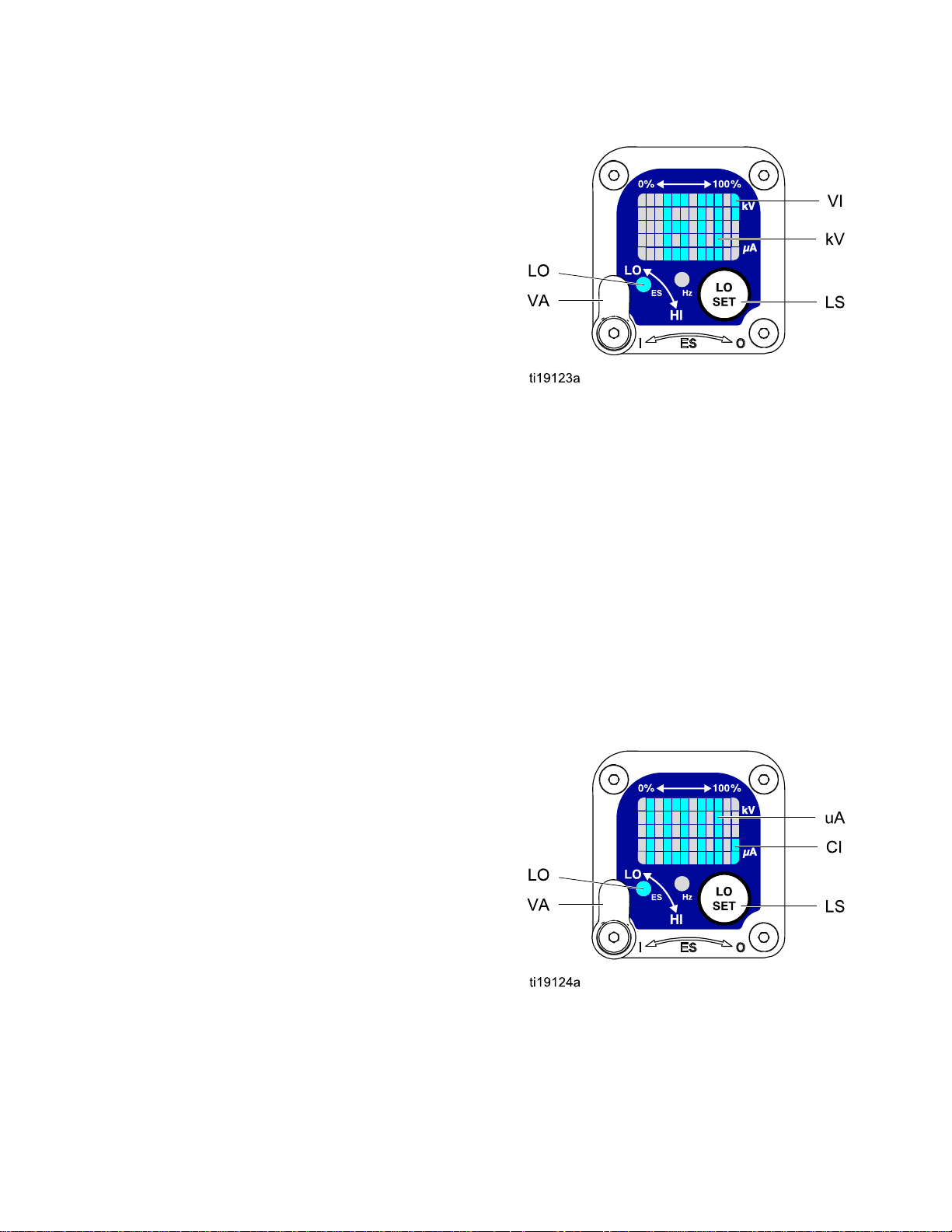
Figure6Voltage(kiloVolts)Screen
Current
Current Current
TheCurrent(microAmperes)Screenisthesecond
screenintheDiagnosticMode.SeeFig.7and
SmartGunKey,page12.Toenterthisscreen,press
theLOSETbuttonwhileintheVoltage(kiloVolts)
Screen.
Thisscreendisplaysthesprayingcurrentofthegun
asanumber(uA),roundedtothenearest5uA.The
twobottomrightLEDs(CI)ofthedisplaypanellight,
indicatingthattheCurrent(microAmperes)Screen
isdisplayed.Thedisplayisareadoutandcannot
bechanged.
(microAmperes)
(microAmperes) (microAmperes)
Screen
Screen Screen
Voltage
Voltage Voltage
TheVoltage(kiloVolts)Screenistherstscreento
appearafterenteringDiagnosticMode.SeeFig.6
andSmartGunKey,page12.Toenterthisscreen,
pressandholdtheLOSETbuttonforapproximately
5secondswhileintheOperatingMode.
Thisscreendisplaysthesprayingvoltageofthe
gunasanumber(kV),roundedtothenearest5kV.
ThetwotoprightLEDs(VI)ofthedisplaypanel
light,indicatingthattheVoltage(kiloVolts)Screen
isdisplayed.Thedisplayisareadoutandcannot
bechanged.
PresstheLOSETbuttontoadvancetothe
Current(microAmperes)Screen,page13.Press
andholdforapproximately5secondstoreturnto
OperatingMode.
(kiloVolts)
(kiloVolts) (kiloVolts)
Screen
Screen Screen
PresstheLOSETbuttontoadvancetothe
AlternatorSpeed(Hertz)Screen,page14.Press
andholdforapproximately5secondstoreturnto
OperatingMode.
Figure7Current(microAmperes)Screen
3A2496H13
Page 14
GunOverview
Alternator
Alternator Alternator
TheAlternatorSpeed(Hertz)Screenisthethird
screenintheDiagnosticMode.SeeFig.8and
SmartGunKey,page12.Toenterthisscreen,
presstheLOSETbuttonwhileintheCurrent
(microAmperes)Screen.
Thisscreendisplaysthealternatorspeedasa3
digitnumber(AS),roundedtothenearest5Hz.The
displayisareadoutandcannotbechanged.Ifthe
alternatorspeedisgreaterthan999Hz,thedisplay
willshow999.
TheHzindicatorlightsgreentoshowthatyouare
viewingtheAlternatorSpeed(Hertz)Screen.
PresstheLOSETbuttontoadvancetothe
LowVoltageLockScreen,page14.Pressandhold
forapproximately5secondstoreturntoOperating
Mode.
Speed
Speed Speed
(Hertz)
(Hertz) (Hertz)
Screen
Screen Screen
Low
Voltage
Low Low
Voltage Voltage
TheLowVoltageLockScreenisthefourth
screenintheDiagnosticMode.SeeFig.9and
SmartGunKey,page12.Toenterthisscreen,press
theLOSETbuttonwhileintheAlternatorSpeed
(Hertz)Screen.
ThisscreendisplaysthestatusoftheLowVoltage
Lock.Ifthesettingislocked,thelockimage(LK)
appearstotheleftoftheLodisplay(LD).Ifthesetting
isunlocked,thelockimagedoesnotappear.
Tochangethelockstatus,pressandholdthe
LOSETbuttonuntilthelockimageappearsor
disappears.Ifthelockisset,theimagewillalso
appearontheLowVoltageSettingScreenwhenin
lowvoltagemode(seeFig.4).
NOTE:
NOTE: NOTE:
screen,becausepressingandholdingtheLOSET
buttonisusedtoturnthelockonoroff.Toexit,
pressLOSETmomentarilytoreturntotheVoltage
(kiloVolts)Screen,thenexitDiagnosticModefrom
there.
DiagnosticModecannotbeexitedfromthis
Lock
Screen
Lock Lock
Screen Screen
Figure8AlternatorSpeed(Hertz)Screen
Figure9LowVoltageLockScreen
14
3A2496H
Page 15
Installation
Installation
Installation Installation
System
System System
Theuseofmultiplegunswithoneisolationcabinet
maycauseelectricshock,re,orexplosion.To
helppreventinjuryorequipmentdamage,useonly
onegunperisolationcabinet.
AGracovoltageisolationsystemmusthavethe
followingfeatures:
•Anisolationenclosurethatpreventspersonsfrom
makingcontactwiththehighvoltagecomponents
beforethesystemvoltageisdischarged.All
componentsoftheisolationsystemthatare
chargedtohighvoltagemustbecontainedwithin
theenclosure.
•Ableedresistortodrainoffthesystemvoltage
whenthespraygunisnotinuse.Ametalpartof
theuidsupplyunitmustbeelectricallyconnected
tothebleedresistor.
•Asafetyinterlockthatautomaticallydischargesthe
systemvoltagewhenanyoneopenstheisolation
enclosure.
Requirements
Requirements Requirements
Install
Install Install
Installingandservicingthisequipmentrequires
accesstopartswhichmaycauseelectricshock
orotherseriousinjuryifworkisnotperformed
properly.
•Donotinstallorservicethisequipmentunless
•Complywithalllocalcodesandregulations
Fig.19showsatypicalelectrostaticairspraysystem.
Itisnotanactualsystemdesign.Forassistance
indesigningasystemtosuityourparticularneeds,
contactyourGracodistributor.
Ventilate
Ventilate Ventilate
the
the the
youaretrainedandqualied.
System
System System
the
Spray
the the
Spray Spray
Booth
Booth Booth
NOTICE
NOTICE NOTICE
Thesystemshouldnothaveanyseverearcing
occurringwhentheisolationmechanismopens
andcloses.Severearcingwillshortenthelifeof
thesystemcomponents.
NOTE:
NOTE: NOTE:
voidiftheelectrostaticspraygunisconnectedtoa
non-Gracovoltageisolationsystemorifthegunis
operatedabove60kV.
Warning
Warning Warning
Mountwarningsignsinthesprayareawherethey
caneasilybeseenandreadbyalloperators.An
EnglishWarningSignisprovidedwiththegun.
TheGracowarrantyandapprovalsare
Sign
Sign Sign
Donotoperatethegununlessventilatingairowis
abovetheminimumrequiredvalue.Providefresh
airventilationtoavoidthebuildupofammableor
toxicvaporswhenspraying,ushing,orcleaning
thegun.Interlockthegunairanduidsupply
topreventoperationunlessventilatingairowis
abovetheminimumrequiredvalue.
Thesprayboothmusthaveaventilationsystem.
Electricallyinterlockthegunairanduidsupplywith
theventilatorstopreventgunoperationanytimethat
theventilationairowfallsbelowminimumvalues.
Checkandfollowalllocalcodesandregulations
regardingairexhaustvelocityrequirements.Verify
theoperationoftheinterlockatleastonceayear.
NOTE:Theminimumallowableairexhaustvelocity
is60feet/minute(19linearmeters/minute).High
velocityairexhaustwilldecreasetheoperating
efciencyoftheelectrostaticsystem.
3A2496H15
Page 16

Installation
Air
Supply
Air Air
Supply Supply
Toreducetheriskofelectricshock,theairsupply
hosemustbeelectricallyconnectedtoatrueearth
ground.Use Use
Hose.
Hose. Hose.
Toreducetheriskofelectricshockorother
seriousinjury,youmustusethered-coloredGraco
ElectricallyConductiveAirHoseforthegunair
supply,andyoumustconnectthehoseground
wiretoatrueearthground.Donotusetheblack
orgray-coloredGracoairhoses.
1.SeeFig.19.Installanairlinelter/water
separator(M)onthemainairsupplylineto
ensureadry,cleanairsupplytothegun.Dirtand
moisturecanruintheappearanceofyournished
workpieceandcancausetheguntomalfunction.
2.TheWB100systemincludesableed-typeair
regulator(N)onthegunairsupplyline(P),to
controlairpressuretothegun.
3.Connectthered-coloredGracoElectrically
ConductiveAirHose(P)betweenthegunair
regulator(N)andthegun’sairinlet.Thegunair
inletttinghasaleft-handthread.Connectthe
airsupplyhosegroundwire(Q)toatrueearth
ground.
Line
Line Line
Use
only
Graco
only only
Graco Graco
Grounded
Grounded Grounded
Air
Supply
Air Air
Supply Supply
Trappedaircancausetheuidsupplyunitto
cycleunexpectedly,whichcanresultinserious
injury,includingsplashinguidintheeyesor
ontheskin.Donotoperatetheequipment
withoutthebleed-typeairvalve(B)installed.
4.TheWB100systemincludesableed-typeair
valve(B).Thebleed-typeairvalveisrequired
toshutoffallairtothesystemandrelieveair
trappedbetweenthevalveandtheuidsupply
unitaftertheairregulatorisshutoff.Connectthe
mainairsupplyline(A)tothebleedvalve.
5.Installanadditionalbleed-typeairvalve(CC)
upstreamoftheairlter(M)toisolatethelter
forservicing.
Ground
Ground Ground
Connectthemaingroundwire(V)toatrueearth
ground.
the
Cabinet
the the
Cabinet Cabinet
163A2496H
Page 17
Installation
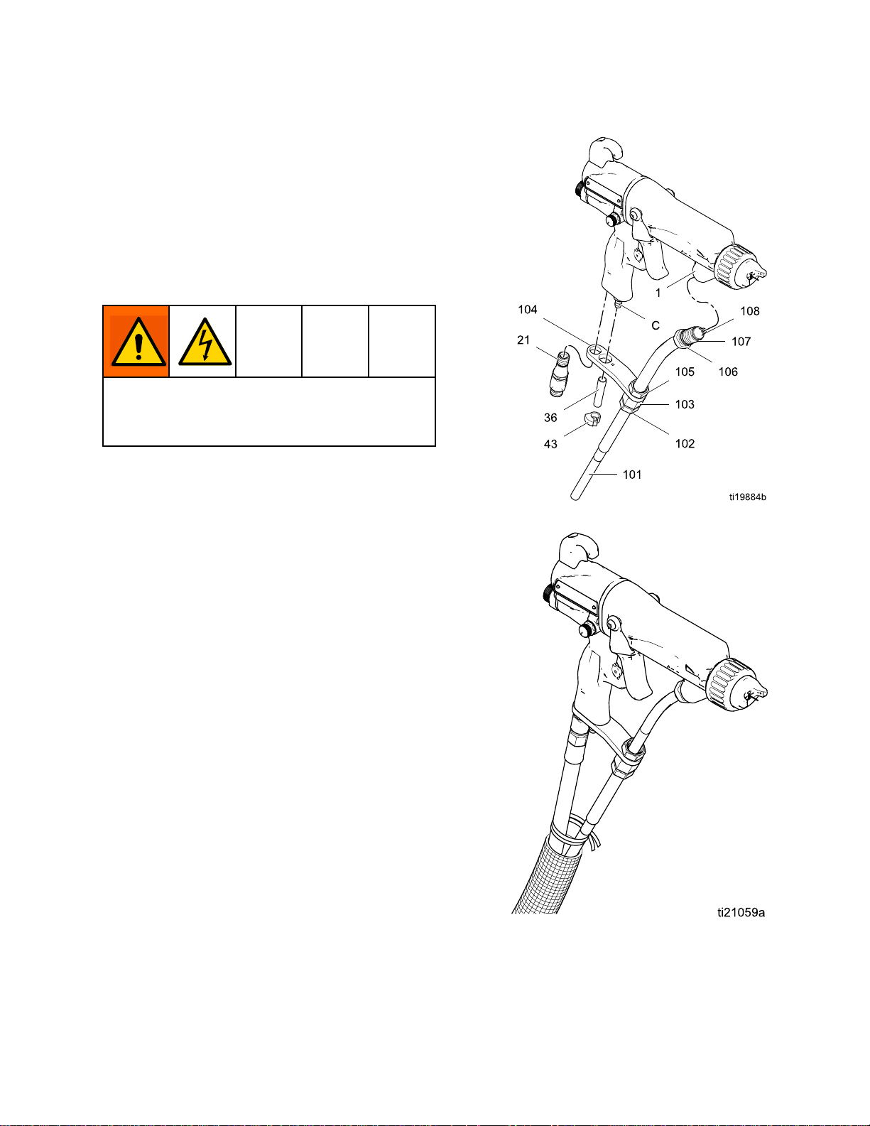
Connect
Connect Connect
AlwaysuseaGracowaterborneuidhosebetween
thevoltageisolationsystemuidoutletandthegun
uidinlet.Thewaterborneuidhose(101)consists
ofaninnerPTFEtube(T)andanabrasion-resistant
outerjacket(J).Shieldedhose24M732alsohas
aconductivelayer(C),Theconductivelayeris
connectedtogroundatthegunttingbracket(104).
Beforeconnectingthewaterborneuidhosetothe
gun,blowitoutwithairandushwithwaterto
removecontaminants.Flushthegunbeforeusingit.
Toreducetheriskofelectricshock,installonly
onecontinuousGracowaterbornehosebetween
theisolateduidsupplyandthegun.Donotsplice
hosestogether.
1.Removethegunairinlettting(21).
NOTE:
NOTE: NOTE:
failureoccurswherehighvoltagearcsthrough
theinnertube,voltagewillbedischargedto
groundthroughtheconductivehoselayer.When
properlyinstalled,theconductivehoselayeris
groundedthroughitsconnectiontothegrounded
enclosure.
Usingunshieldeduidhosesminimizesthe
systemcapacitance,resultinginfasterresponse
timesandalargereductionintheenergystored
inthesystem,ascomparedtoshieldedhoses.
However,withoutthegroundshield,aweak
staticchargecanoccasionallybuilduponthe
outersurfaceofthehose.Tominimizeany
staticchargefeltonthehosesurface,bundle
theairanduidhosetogether,andwrapwitha
protectivecover,asshown.
the
Waterborne
the the
Waterborne Waterborne
Inashieldedhosesystem,ifahose
Fluid
Fluid Fluid
Hose
Hose Hose
Figure10ConnecttheFluidHose
Figure11BundlingtheAirandFluidHoses
3A2496H
17
Page 18
Installation
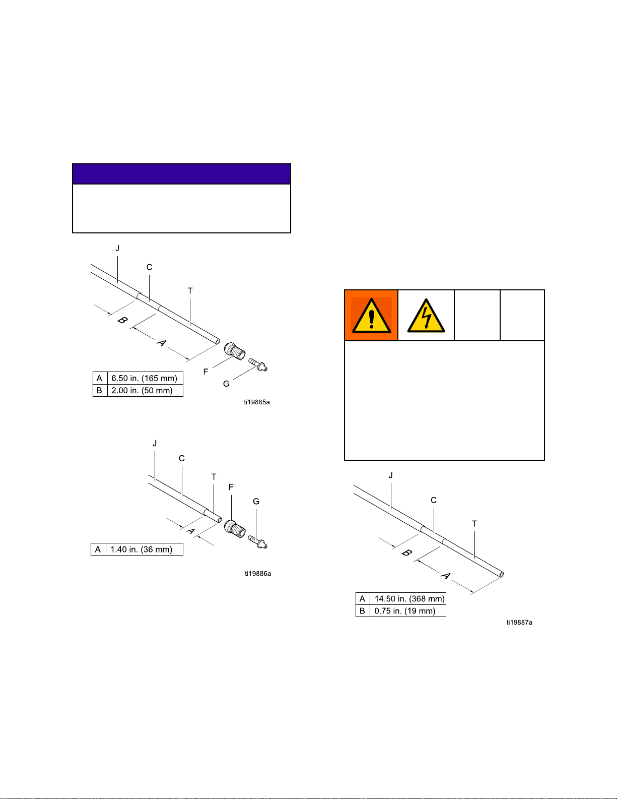
2.Fortheuidhosetotproperly,itmustbe
strippedandassembledtothedimensionsshown
inFig.12.Applydielectricgreasetotheinner
tube(T)ofthehose.Slidethetting(F)onto
thetube(T).Pressthebarbedtting(G)intothe
tubeuntilitsshoulderbottomsonthetube.A
newGracowaterborneuidhosecomesfully
assembledtothesedimensions.
NOTICE
NOTICE NOTICE
Becarefulnottocutintotheinnertube(T)of
thehosewhenstrippingthehose.Nicksor
cutsinthePTFEtubewillcausepremature
hosefailure.
Figure12ShieldedHose24M732Dimensions
atGun
4.Loosenthestrainreliefnut(102)sothebracket
canmovefreelyonthehose.
5.Alignthebracket(104)holeswiththeairinletand
exhaustoutlet.Securewiththeairinlettting
(21).Tightenthestrainreliefnut(102)tosecure
thehose.
6.Checkthatthenut(105)istightenedsecurelyto
theferrulehousing(103).
7.Presstheexhausttube(36)ontotheexhaust
valvebarb(C).Securewiththeclamp(43).
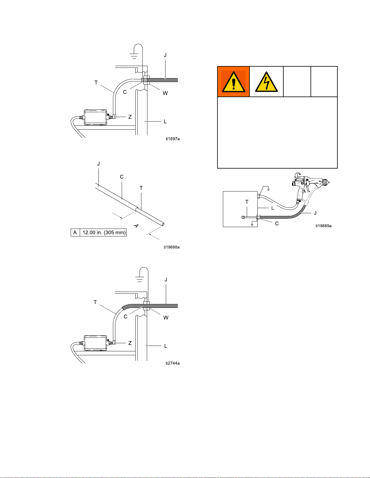
8.Connecttheotherendofthehosetotheisolated
uidsupplyasfollows:
GracoWB100Enclosure:
a.
thestrainrelieftting(W).Ensureconductive
layer(C)haspassedthroughtting.Tighten
to55in-lb(6.2N•m).Pullbackonhoseto
checkitissecure.
For
Shielded
For For
Shielded Shielded
Conductivehoselayer(C)mustbe
groundedthroughitsconnectiontothe
isolationsystem’sgroundedenclosure(L)
orgroundedfence.Tomaintaingrounding
continuity,theconductivehoselayer(C)
mustbeengagedintheferrulewhenthe
strainreliefnutistightened.Failureto
properlyinstallthehoseinthestrainrelief
couldresultinanelectricshock.
Hose
Hose Hose
Slidehosethrough
Systems:
Systems: Systems:
Figure13UnshieldedHose24M733Dimensions
atGun
3.Generouslyapplydielectricgrease(44)tothe
o-ring(107)andthethreadsofthetting(106).
Pullthettingback1-1/2in.(38mm)andapply
greasetotheexposedPTFEhosetollthearea
betweenthehoseandthetting.Makesurethe
barrelinletiscleananddry,thenscrewthetting
intotheuidinletofthegunbarrel(1).
Figure14ShieldedHose24M732
DimensionsatWB100Enclosure
183A2496H
Page 19
Installation
Figure15ShieldedHose24M732
ConnectionatWB100Enclosure
Non-GracoIsolatedEnclosure:
b.
hoseasinstructedintheisolationsystem
manual.
For
Shielded
For For
Shielded Shielded
Conductivehoselayer(C)mustbe
groundedthroughitsconnectiontothe
isolationsystem’sgroundedenclosure(L)
orgroundedfence.Tomaintaingrounding
continuity,theconductivehoselayer(C)
mustbeengagedintheferrulewhenthe
strainreliefnutistightened.Failureto
properlyinstallthehoseinthestrainrelief
couldresultinanelectricshock.
Hose
Systems:
Hose Hose
Systems: Systems:
Connect
Figure16UnshieldedHose24M733
DimensionsatWB100Enclosure
Figure17UnshieldedHose24M733
ConnectionatWB100Enclosure
Figure18ShieldedFluidHoseConnection
atNon-GracoIsolationEnclosure
c.Connecttheendofthetube(T)tothepump
uidoutlettting(Z).
NOTE:
NOTE: NOTE:
arevoidiftheelectrostaticspraygunis
connectedtoanon-Gracovoltageisolation
systemorifthegunisoperatedabove60kV.
TheGracowarrantyandapprovals
3A2496H19
Page 20
Installation
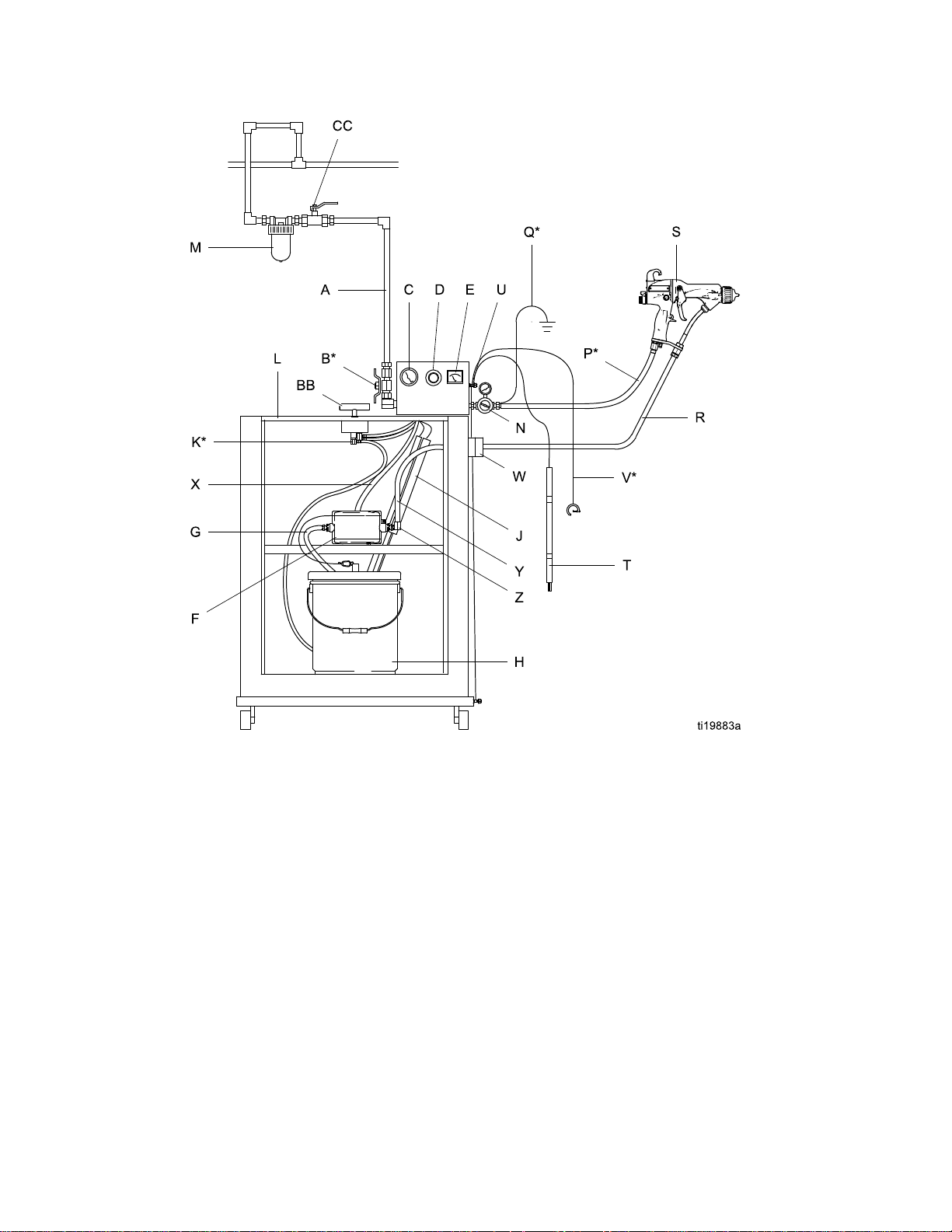
Figure19TypicalInstallation,ProXpWB100
WaterborneSystem
203A2496H
Page 21

Installation
Typical
Typical Typical
Installation
Installation Installation
Item
Item Item
A
B*Bleed-TypeAirShutoffValve
CPumpAirPressureGauge
DPumpAirPressureRegulator
EkVMeter
FPump
GPumpSuctionHose
H
J*
K*EnclosureSafetyInterlock
LIsolatedEnclosure
M
N
P*GracoRedGroundedAirHose(left-handthreads)
Q*GunAirHoseGroundWire
Key
Key Key
Description
Description Description
MainAirSupplyLine
PaintContainer
BleedResistor
GunAirLineFilter
GunAirPressureRegulator
R
SWaterborneElectrostaticAirSprayGun
T
U
V*MainGroundWire
W
X
Y
Z
AA
BB
CCAccessoryBleed-TypeAirShutoffValve
*Theseitemsarerequiredforsafeoperation.TheyareincludedwiththeWB100system.
GracoWaterborneFluidHose
GroundingRod
GroundTerminal
StrainReliefFitting
PumpAirSupplyLine
GroundingCylinder
PumpFluidOutletFitting
IsolatedEnclosureDoor(notshown,toillustrateinternalcomponents.Doormustbeclosed
andlockedtooperatesystem).
EnclosureT-HandleLockingScrew(partofdoorassembly)
3A2496H
21
Page 22
Installation
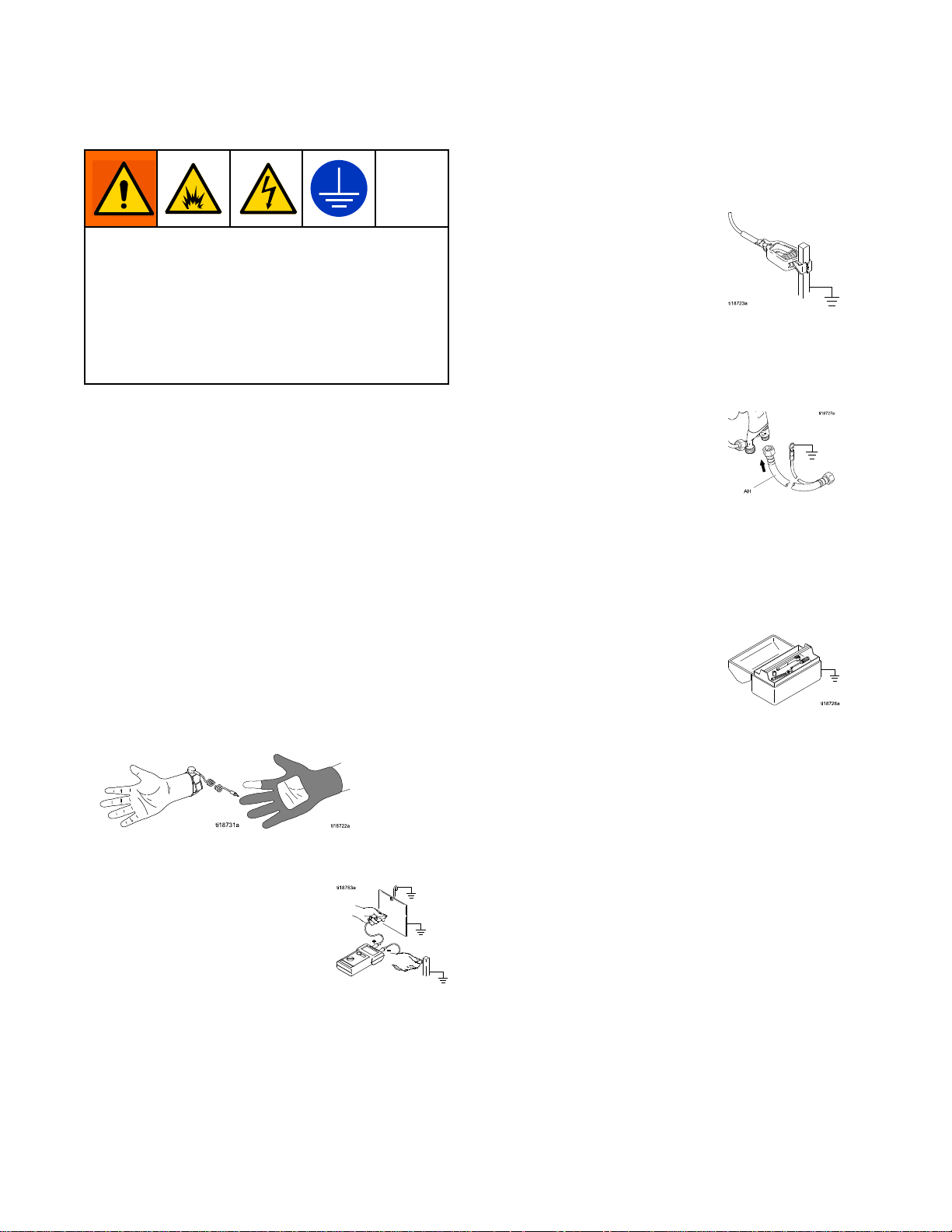
Grounding
Grounding Grounding
Theequipmentmustbegroundedtoreducethe
riskofstaticsparkingandelectricshock.Electric
orstaticsparkingcancausefumestoigniteor
explode.Impropergroundingcancauseelectric
shock.Groundallequipment,personnel,objects
beingsprayed,andconductiveobjectsinorclose
tothesprayarea.Theresistancemustnotexceed
1megohm.Groundingprovidesanescapewire
fortheelectriccurrent.
Whenoperatingtheelectrostaticgun,any
ungroundedobjects(suchaspeople,containers,and
tools)inthespraylocationcanbecomeelectrically
charged.
Thefollowingareminimumgroundingrequirements
forabasicelectrostaticsystem.Yoursystemmay
includeotherequipmentorobjectswhichmustbe
grounded.Yoursystemmustbeconnectedtoa
trueearthground.Checkgroundconnectionsdaily.
Checkyourlocalelectricalcodesandregulationsfor
detailedgroundinginstructions.
Allpersonsenteringthesprayarea:
•
shoeshavingconductivesolessuchasleather,
orwearpersonalgroundingstraps.Donot
wearshoeswithnon-conductivesolessuchas
rubberorplastic.Ifglovesarenecessary,wear
theconductiveglovessuppliedwiththegun.If
non-Gracoglovesareworn,cutoffngersorpalm
areaofglovestoensureyourhandcontactsthe
groundedgunhandle.
•
Objectbeingsprayed:
cleanandgroundedatalltimes.
Keeptheworkpiecehangers
mustwear
•
VoltageIsolationSystem:
voltageisolationsystemtoatrueearthground.
SeeGroundtheCabinet,page16.
•
ElectrostaticAirSprayGun:
byconnectingthered-coloredGracoGrounded
AirHosetothegun,andconnectingtheair
hosegroundwiretoatrueearthground.See
CheckGunElectricalGrounding,page38.
•
GracoShieldedWaterborneFluidHose
(24M732):
conductivelayer.Installasinstructedunder
ConnecttheWaterborneFluidHose,page17.
•
Allelectricallyconductiveobjectsordevicesinthe
sprayarea:
•
Fluidandwastecontainers:
wastecontainersinthesprayarea.Donotusepail
linersunlesstheyareconductiveandgrounded.
Whenushingthespraygun,thecontainerused
tocatchtheexcessuidmustbeelectrically
conductiveandgrounded.
Aircompressors:
•
tothemanufacturer'srecommendations.
•
Allairlines
groundedhoseswithamaximumof100feet(30.5
m)combinedhoselengthtoensuregrounding
continuity.
Thehoseisgroundedthroughthe
mustbeproperlygrounded.
Groundtheequipmentaccording
mustbeproperlygrounded.Useonly
Electricallyconnectthe
Groundthegun
Groundalluidand
22
3A2496H
Page 23

•
Theoorofthesprayarea:
conductiveandgrounded.Donotcovertheoor
withcardboardoranynon-conductivematerial
whichwouldinterruptgroundingcontinuity.
mustbeelectrically
•
Allsolventpails:
metalcontainers,whichareconductive.Donot
useplasticcontainers.Useonlynon-ammable
solvents.Donotstoremorethanthequantity
neededforoneshift.
Useonlyapproved,grounded
Installation
3A2496H23
Page 24
Installation
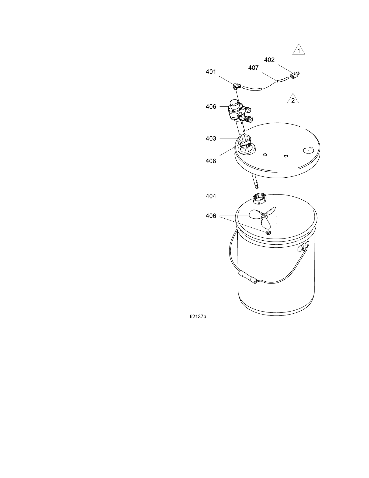
Agitator
Agitator Agitator
ToaddanagitatortotheGracoisolationsystem,order
PartNo.245895.See245895AgitatorKit,page108,
forthekitpartslist.
1.Dischargethesystemvoltage(seeFluidVoltage
DischargeandGroundingProcedure,page39).
2.Relievethepressure(see
PressureReliefProcedure,page39).
3.Opentheisolatedenclosuredoor.
4.Removethebackofthecontrolbox(258).
5.Removetube(A2)fromelbow(282)attheair
manifold;seeTubingandWiring,page84.
InstalltheYtting(402)intotheelbow.Install
tubes(A2)and(407)intotheYtting.Routethe
agitatortube(407)intothecabinet.
6.Replacethebackofthecontrolbox(258).
7.Assembletheotherpartsofthekitasshown.
Securetheagitatorwiththesetscrew(408).
8.Returnthesystemtoservice.
Kit
Accessory
Kit Kit
Accessory Accessory
Figure20245895AgitatorKit
24
3A2496H
Page 25
Installation
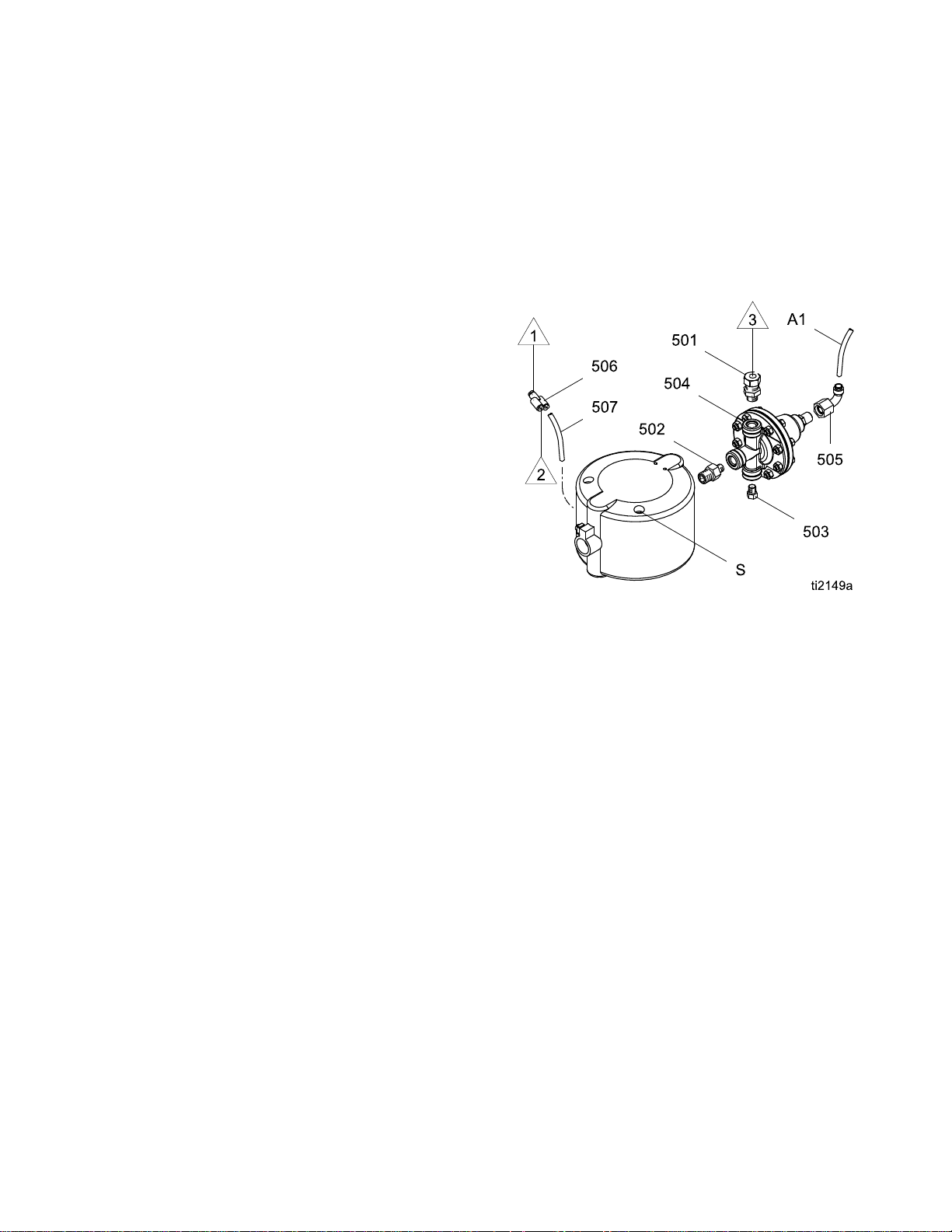
Fluid
Fluid Fluid
ToaddauidregulatortotheGracoisolation
system,orderPartNo.245944.See
245944FluidRegulatorKit,page108forthe
kitpartslist.
1.Dischargethesystemvoltage(seeFluidVoltage
2.Relievethepressure(see
3.Opentheisolatedenclosuredoor.
4.Removethe1/4in.(6mm)ODtube(A1)fromthe
5.Removethewaterborneuidhosefromthepump
6.Unscrewthetwopumpmountingscrews(S)and
7.Removethebackofthecontrolbox(258).
8.Removetube(A2)fromelbow(282)attheair
9.Replacethebackofthecontrolbox(258).
10.Assembletheuidregulatorkitasshown.
11.Reinstallthepumpintheisolationenclosure.
Regulator
Regulator Regulator
DischargeandGroundingProcedure,page39).
PressureReliefProcedure,page39).
pumpairinlet;seeTubingandWiring,page84.
uidoutlettting(231)andremovethetting.
removethepumpfromtheisolationenclosure.
manifold;seeTubingandWiring,page84.
InstalltheYtting(506)intheelbow.Install
tubes(A2)and(507)intotheYtting.Routethe
tube(507)intothecabinet.
Usethetwomountingholestotheleftofthe
holesusedpreviously,toallowclearanceforthe
uidregulator.
Kit
Accessory
Kit Kit
Accessory Accessory
12.Connecttube(A1)totheairinletofuidregulator
(504).Connecttube(507)tothepumpairinlet.
13.Connectthewaterborneuidhosetotheuid
regulatoroutlettting(501).
14.Returnthesystemtoservice.
NOTE:
NOTE: NOTE:
217)willnowoperatetheairpiloteduidregulator
(504).Thepumpwillnowoperateattheinletair
pressure.
Figure21245944FluidRegulatorKit
Thecabinetairregulatorandgauge(216,
3A2496H25
Page 26
GunSetup
Gun
Gun Gun
Gun
Gun Gun
Toreducetheriskofreandexplosion,uidsused
mustmeetthefollowingammabilityrequirements:
•FM, FM,
•CE CE
Contactwiththechargedcomponentsofthespray
gunwillcauseanelectricshock.Donottouchthe
gunnozzleorelectrodeorcomewithin4in.(102
mm)ofthefrontofthegunduringoperationor
untilperformingtheFluidVoltageDischargeand
GroundingProcedure,page39.
FollowtheFluidVoltageDischargeandGrounding
Procedure,page39whenyoustopsprayingand
wheneveryouareinstructedtodischargethe
voltage.
Setup
Setup Setup
Setup
Setup Setup
FM,
FMc
FMc FMc
Materialdoesnotsustainburninginaccordance
withtheStandardTestMethodforSustained
BurningofLiquidMixtures,ASTMD4206.
CE
EN
- --EN EN
Materialswhichcannotbeignited,inanymixture
withair,byanenergysourceoflessthan500mJ.
Procedure
Procedure Procedure
Approved:
Approved: Approved:
50059
50059 50059
Compliant:
Compliant: Compliant:
Foradditionalstepstosetupspecialtyguns,
seeSoftSprayGunSetupProcedure,page30,
RoundSprayGunSetupProcedure,page33,
HVLPGunSetupProcedure,page31,
AbrasiveMaterialGunSetupProcedure,page35,
andMoldReleaseGunSetupProcedure,page36.
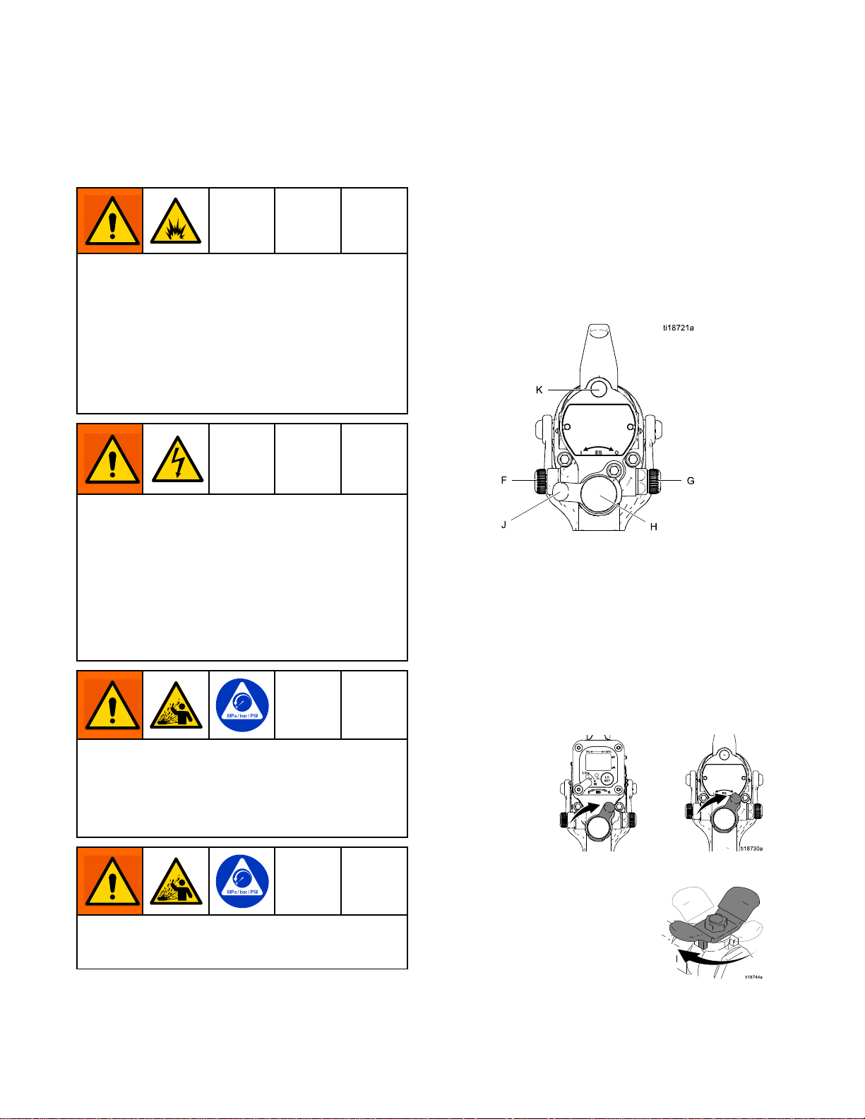
Seethegurebelowtolocatetheelectrostaticgun
controls.
Figure22ElectrostaticGunControls
1.Thegunisshippedwiththeuidnozzleandair
capinstalled.Checkthattheretainingringis
tight.
NOTE:
NOTE: NOTE:
sizeuidnozzleoraircap,see
FluidNozzleSelectionChart,page93and
AirCapSelectionGuide,page96.
Toinstallthenozzleandaircap,see
AirCapandNozzleReplacement,page59.
2.TurnOFF(O)theESOn-Offswitch(J).
Toselectadifferent
Toreducetheriskofcomponentrupture,which
cancauseseriousinjury,donotexceedthe
maximumworkingpressureofthelowestrated
systemcomponent.Thisequipmenthasa100psi
(0.7MPa,7bar)maximumworkingairanduid
pressure.
3.Shutofftheairbleedvalvetothegun.
Toreducetheriskofaninjury,followthe
PressureReliefProcedure,page39wheneveryou
areinstructedtorelievethepressure.
4.Checkgunresistance.Followthestepsin
TestGunResistance,page47.
263A2496H
Page 27
GunSetup
5.Connectthewaterbornehose.Followthesteps
inConnecttheWaterborneFluidHose,page17.
6.ConnecttheredGracogroundedairhosetothe
gunairinlet.Thegunairinletttinghasleft-hand
threads.SeeAirSupplyLine,page16.
7.FollowallstepsinGrounding,page22.
8.Followallstepsin
CheckGunElectricalGrounding,page38.
Readingmustbelessthan100ohms.
9.Connecttheexhausttubeandsecurewiththe
clampprovided.
10.Flushifneeded.SeeFlushing,page42.
11.Positiontheaircapasneeded.
13.Fullyopentheuidadjustmentvalve(H)
counterclockwise.
14.Fullyopentheatomizingairrestrictorvalve(G)
clockwise.
15.TurnON(I)theESOn-Offswitch(J).
12.Fullyopenthefanairadjustmentvalve(F)
counterclockwise.
3A2496H
WhentheESOn-OffswitchisturnedON(I),
theuidsupplyischargedwithhighvoltage
untilthevoltageisdischarged.Contactwith
thechargedcomponentsofthespraygunwill
causeanelectricshock.Donottouchthegun
nozzleorelectrodeorcomewithin4in.(102
mm)ofthefrontofthegunduringoperation.
27
Page 28
GunSetup
16.Setthegunairregulatortodeliveraminimum
45psi(0.32MPa,3.2bar)atthegunwhen
triggered,toensurefullsprayingvoltage.
Table
Table Table
using
using using
mm)
mm) mm)
Pressure
2 22. ..Pressure Pressure
Air
Hose
Air Air
Hose Hose
Length
Length Length
in ininft ftft(m) (m)
5/16
5/16 5/16
diameter
diameter diameter
15(4.6)55(0.38,3.8)
25(7.6)65(0.45,4.5)
50(15.3)80(0.56,5.6)
Drop
Drop Drop
(m)
inch
(8
inch inch
(8 (8
hose
hose hose
18.Shutofftheairtothegun.TurnOFF(O)theES
On-Offswitch(J).
19.Startthepump.Adjusttheuidregulatoruntilthe
streamfromtheguntravels8-12in.(200-300
mm)beforefallingoff.Typically,ifuidpressure
isbelow5psi(.04MPa,0.4bar)orabove30psi
(0.21MPa,2.1bar),achangeofnozzlesizeis
recommended.
Air
Regulator
Air Air
Regulator Regulator
psi
in ininpsi psi
with
gun
with with
gun gun
Setting
Setting Setting
(MPa,
(MPa, (MPa,
bar)
bar) bar)
triggered
triggered triggered
17.VerifythattheESindicator(K)[Hzindicatoron
Smartguns]islit.
Table
Table Table
Indicator
Indicator Indicator
Amber
LED
3 33. ..LED LED
Color
Color Color
Green
Red
Indicator
Indicator Indicator
Whenspraying,theindicator
shouldremaingreen,indicating
sufcientairpressuretothe
alternatorturbine.
Iftheindicatorchangestoamber
afteronesecond,theairpressure
istoolow.Increaseairpressure
untiltheindicatorisgreen.
Iftheindicatorchangestored
afteronesecond,theairpressure
istoohigh.Decreaseairpressure
untiltheindicatorisgreen.To
maintainahigherapplicationair
pressure,installESOn/OffValve
RestrictorKit26A160.Adjustthe
pressureasneededtoensurethe
indicatorremainsgreen.
Colors
Colors Colors
Description
Description Description
20.Turnontheairtothegun.TurnON(I)theES
On-Offswitch(J).
283A2496H
Page 29
GunSetup
21.Sprayatestpattern.Checktheatomization.
•Ifover-atomizationoccursatminimum
pressure,adjusttheatomizingairrestrictor
valve.
•Ifatomizationisinadequate,increaseair
pressureordecreaseuidow.
22.Adjustthefanairadjustmentvalve.
•Fullyopenthefanairadjustmentvalve,
counterclockwise,forthelongestpattern.
•Turnthevalveclockwisetorestrictthefanair
andcreateashorterpattern.
WhentheESOn-OffswitchisturnedON(I),
theuidsupplyischargedwithhighvoltage
untilthevoltageisdischarged.Contactwith
thechargedcomponentsofthespraygunwill
causeanelectricshock.Donottouchthegun
nozzleorelectrodeorcomewithin4in.(102
mm)ofthefrontofthegunduringoperation.
23.Sprayatestpiece.Examinetheedges
forcoverage.Ifwrapispoor,see
Troubleshooting,page51.
3A2496H29
Page 30
GunSetup
Soft
Spray
Soft Soft
Spray Spray
Gun
Gun Gun
Setup
Setup Setup
Procedure
Procedure Procedure
Toconvertaguntoachieveasoftspraypatternfor
smallorlightweightparts,dothefollowing:
1.Installasoftsprayaircap.See
AirCapSelectionGuide,page96.
2.Forbestresults,installa1.0mm
or1.2mmuidnozzle.See
FluidNozzleSelectionChart,page93.
3.Followsteps1–13inthe
GunSetupProcedure,page26.
4.Adjusttheatomizingair.Fullyclosetheatomizing
airrestrictorvalve(G)counterclockwise.Then,
opentheatomizingairrestrictorvalve(G)one
halfturntooneturn.
5.TurnON(I)theESOn-Offswitch(J).
Table
Table Table
using
using using
mm)
mm) mm)
7.VerifythattheESindicator(K)[Hzindicatoron
Smartguns]islit.
Table
Table Table
Indicator
Indicator Indicator
Amber
Pressure
4 44. ..Pressure Pressure
Air
Hose
Air Air
Hose Hose
Length
Length Length
Color
Color Color
Green
in ininft ftft(m) (m)
5/16
5/16 5/16
diameter
diameter diameter
15(4.6)55(0.38,3.8)
25(7.6)65(0.45,4.5)
50(15.3)80(0.56,5.6)
LED
5 55. ..LED LED
Drop
Drop Drop
(m)
inch
(8
inch inch
(8 (8
hose
hose hose
Indicator
Indicator Indicator
Whenspraying,theindicator
shouldremaingreen,indicating
sufcientairpressuretothe
alternatorturbine.
Iftheindicatorchangestoamber
afteronesecond,theairpressure
istoolow.Increaseairpressure
untiltheindicatorisgreen.
Colors
Colors Colors
Description
Description Description
Air
Regulator
Air Air
Regulator Regulator
psi
(MPa,
in ininpsi psi
(MPa, (MPa,
with
gun
with with
triggered
gun gun
triggered triggered
Setting
Setting Setting
bar)
bar) bar)
6.Setthegunairregulatortodeliveraminimum
45psi(0.32MPa,3.2bar)atthegunwhen
triggered,toensurefullsprayingvoltage.
Red
8.Continuewithsteps18–23inthe
GunSetupProcedure,page26.
NOTE:
NOTE: NOTE:
productionrateof3.5oz/min(100cc/min).For
bestsoftsprayresults,limittheproductionrate
to7oz/min(200cc/min)orless.
NOTE:
NOTE: NOTE:
much,adjusttheatomizingairrestrictorvalve
(G)counterclockwiseslightlytolimittheairow.
Toimproveatomization,adjusttheatomizingair
restrictorvalve(G)clockwiseslightlytoincrease
theairowordecreasetheuidow.
Iftheindicatorchangestored
afteronesecond,theairpressure
istoohigh.Decreaseairpressure
untiltheindicatorisgreen.To
maintainahigherapplicationair
pressure,installESOn/OffValve
RestrictorKit26A160.Adjustthe
pressureasneededtoensurethe
indicatorremainsgreen.
Thesoftsprayaircapisoptimizedfora
Iftheobjectbeingsprayedismovingtoo
303A2496H
Page 31

GunSetup
HVLP
HVLP HVLP
TosprayHVLP,airpressureattheaircapmustbe
10PSI(0.07MPa,0.7bar)orless.Tosetupan
HVLPgun,dothefollowing:
1.InstallanHVLPaircap.See
2.Followsteps1–11inthe
3.Fullyopentheuidadjustmentvalve(H)
4.Adjusttheairintheaircap.
Gun
Gun Gun
AirCapSelectionGuide,page96.
GunSetupProcedure,page26.
counterclockwise.
a.Fullyclosethefanairadjustmentvalve(F)
clockwise,thenopenitcounterclockwisetwo
turns.
b.Fullyclosetheatomizingairrestrictorvalve
(G)counterclockwise,thenopenitclockwise
oneturn.
Setup
Setup Setup
Procedure
Procedure Procedure
Table
Table Table
using
using using
mm)
mm) mm)
NOTE:
NOTE: NOTE:
volumeofairtoatomizepaintatlow
pressure.Gunairregulatorstaticpressure
settingsof70PSIorhigheraretypically
required.Toachievetherequiredgunair
pressures,useashorterlengthairhoseora
largerdiameterairhose.SeeGroundedAir
HosesinHoses,page107.
e.VerifythattheESindicator(K)[Hzindicator
onSmartguns]islit.
Table
Table Table
Indicator
Indicator Indicator
Pressure
6 66. ..Pressure Pressure
Air
Hose
Air Air
Hose Hose
Length
Length Length
Color
Color Color
in ininft ftft(m) (m)
5/16
5/16 5/16
diameter
diameter diameter
15(4.6)55(0.38,3.8)
25(7.6)65(0.45,4.5)
50(15.3)80(0.56,5.6)
TheHVLPaircaprequiresahigh
LED
7 77. ..LED LED
Drop
Drop Drop
(m)
inch
(8
inch inch
(8 (8
hose
hose hose
Indicator
Indicator Indicator
Colors
Colors Colors
Description
Description Description
Air
Regulator
Air Air
Regulator Regulator
Setting
Setting Setting
(MPa,
(MPa, (MPa,
with
gun
with with
gun gun
psi
in ininpsi psi
bar)
bar) bar)
triggered
triggered triggered
Green
Amber
c.TurnON(I)theESOn-Offswitch(J).
Red
d.Setthegunairregulatortodeliveraminimum
45psi(0.32MPa,3.2bar)atthegunwhen
triggered,toensurefullsprayingvoltage.
Whenspraying,theindicator
shouldremaingreen,indicating
sufcientairpressuretothe
alternatorturbine.
Iftheindicatorchangesto
amberafteronesecond,theair
pressureistoolow.Increase
airpressureuntiltheindicator
isgreen.
Iftheindicatorchangesto
redafteronesecond,theair
pressureistoohigh.Decrease
airpressureuntiltheindicator
isgreen.Tomaintainahigher
applicationairpressure,install
ESOn/OffValveRestrictorKit
26A160.Adjustthepressure
asneededtoensurethe
indicatorremainsgreen.
3A2496H31
Page 32

GunSetup
f.VerifythattheaircappressuresmeetHVLP
requirementsof10PSI(0.07MPa,0.7
bar)orlessusingtheHVLPvericationkit
25E919.Seemanual3A6833.Adjustthe
fanairadjustmentvalve(F)andatomizing
airrestrictorvalvetoachieve10PSIorless
asneeded.
g.VerifythattheESindicator(K)[Hzindicator
onSmartguns]remainsgreen.
5.Continuewithsteps18–23inthe
GunSetupProcedure,page26.
323A2496H
Page 33

GunSetup
Round
Round Round
Toachievearoundspraypattern,dothefollowing:
1.Installaroundspraykit.SeeRoundSpray
2.Followsteps1–11inthe
3.Fullyopentheuidadjustmentvalve(H)
4.Adjusttheairintheaircap.
Spray
Spray Spray
AccessoriesinGunAccessories,page105.To
achieveasoftpatternforsmallpartsorincreased
transferefciency,selectthemediumpatternor
smallpatternmodels.
GunSetupProcedure,page26.
counterclockwise.
a.Fullyclosetheatomizingairrestrictorvalve
(G)counterclockwise.Then,openthe
atomizingairrestrictorvalve(G)oneturn.
Gun
Gun Gun
Setup
Setup Setup
Procedure
Procedure Procedure
6.Setthegunairregulatortodeliveraminimum
45psi(0.32MPa,3.2bar)atthegunwhen
triggered,toensurefullsprayingvoltage.
Table
Table Table
using
using using
mm)
mm) mm)
Pressure
8 88. ..Pressure Pressure
Air
Hose
Air Air
Hose Hose
Length
Length Length
in ininft ftft(m) (m)
5/16
5/16 5/16
diameter
diameter diameter
15(4.6)55(0.38,3.8)
25(7.6)65(0.45,4.5)
Drop
Drop Drop
(m)
inch
(8
inch inch
(8 (8
hose
hose hose
Air
Regulator
Air Air
Regulator Regulator
psi
in ininpsi psi
with
gun
with with
gun gun
Setting
Setting Setting
(MPa,
(MPa, (MPa,
bar)
bar) bar)
triggered
triggered triggered
b.Fullyclosethefanairadjustmentvalve(F)
clockwise.
5.TurnON(I)theESOn-Offswitch(J).
50(15.3)80(0.56,5.6)
7.VerifythattheESindicator(K)[Hzindicatoron
Smartguns]islit.
Table
Table Table
Indicator
Indicator Indicator
Amber
LED
9 99. ..LED LED
Color
Color Color
Green
Red
Indicator
Indicator Indicator
Whenspraying,theindicator
shouldremaingreen,indicating
sufcientairpressuretothe
alternatorturbine.
Iftheindicatorchangestoamber
afteronesecond,theairpressure
istoolow.Increaseairpressure
untiltheindicatorisgreen.
Iftheindicatorchangestored
afteronesecond,theairpressure
istoohigh.Decreaseairpressure
untiltheindicatorisgreen.To
maintainahigherapplicationair
pressure,installESOn/OffValve
RestrictorKit26A160.Adjustthe
pressureasneededtoensurethe
indicatorremainsgreen.
Colors
Colors Colors
Description
Description Description
3A2496H33
Page 34

GunSetup
8.Shutofftheairtothegun.TurnOFF(O)theES
On-Offswitch(J).
9.Startthepump.Adjusttheuidregulatorto
achievetheproductionratethatyouwant.
NOTE:
NOTE: NOTE:
aproductionrateof5oz/min(150cc/min).For
bestroundsprayresults,limittheproductionrate
to10oz/min(300cc/min)orless.
10.Turnontheairtothegun.TurnON(I)theES
On-Offswitch(J).
Theroundsprayaircapisoptimizedfor
11.Sprayatestpattern.Checktheatomization.
NOTE:
NOTE: NOTE:
objectbeingsprayedismovingtoomuch,
adjusttheatomizingairrestrictorvalve(G)
counterclockwiseslightlytolimittheairow.To
improveatomization,adjusttheatomizingair
restrictorvalve(G)clockwiseslightlytoincrease
theairowordecreasetheuidow.
12.Adjustthepatternsize.
•Forthelargestspraypattern,fullyclosethefan
•Forthesmallestspraypattern,fullyopenthe
13.Sprayatestpiece.Examinetheedges
forcoverage.Ifwrapispoor,see
Troubleshooting,page51.
Iftheatomizationistoone,orifthe
airadjustmentvalve(F)clockwise.
fanairadjustmentvalve(F)counterclockwise.
343A2496H
Page 35

GunSetup
Abrasive
Abrasive Abrasive
NOTE:
NOTE: NOTE:
taskseachday:
•Cleanthegun.SeeCleantheGunDaily,page44.
•Inspecttheelectrodeandreplaceifdamaged.See
ElectrodeReplacement,page61.
Toextendwearlifewithabrasive,metallic,and
extremelyabrasivematerials,dothefollowing:
1.Toconvertagunforabrasivematerials:
•Selectaprecisionhighwear
orhighwearnozzle.See
FluidNozzleSelectionChart,page93.
Sizethenozzleproperlytoreduceuid
pressurebelow30psi(0.21MPA,2.1bar),
producingan8-12in(200-300mm)uid
stream.
•Use24N632ESOn-OffandFixedFluidValve.
2.Followsteps1–18inthe
GunSetupProcedure,page26.
3.Startthepump.Adjusttheuidregulatoruntilthe
streamfromtheguntravels8-12in.(200-300
mm)beforefallingoff.Typically,ifuidpressure
isbelow5psi(.04MPa,0.4bar)orabove30psi
(0.21MPa,2.1bar),achangeofnozzlesizeis
recommended.
Material
Material Material
Toextendwearlife,performthefollowing
Gun
Gun Gun
Setup
Setup Setup
Procedure
Procedure Procedure
4.Turnontheairtothegun.TurnON(I)theES
On-Offswitch(J).
5.Sprayatestpattern.Checktheatomization.If
over-atomizationoccursatminimumpressure,
adjusttheatomizingairrestrictorvalve.If
atomizationisinadequate,increaseairpressure
ordecreaseuidow.
NOTE:
NOTE: NOTE:
knobinthefullowpositionatalltimesor
install24N632ESOn-OffandFixedFluidValve.
Alwaysuseanexternaluidregulator.Donot
usetheuidadjustmentknobtosettheuid
pressure.
Operatethegunwiththeuidadjustment
NOTE:
NOTE: NOTE:
toextendelectrodewirewearlife.Reducethe
guninletairpressureoradjusttheatomizingair
restrictorvalve(G)counterclockwisetoreduce
atomizingairwhentheapplicationallows.
6.Adjustthefanairadjustmentvalve.
•Fullyopenthefanairadjustmentvalve,
•Turnthevalveclockwisetorestrictthefanair
NOTE:
NOTE: NOTE:
extendelectrodewirewearlife.Reducethegun
inletairpressureoradjustthefanairadjustment
valve(F)clockwisetoreducefanairwhenthe
applicationallows.
7.Sprayatestpiece.Examinetheedges
forcoverage.Ifwrapispoor,see
Troubleshooting,page51.
Usetheminimumatomizingairpressure
counterclockwise,forthelongestpattern.
andcreateashorterpattern.
Usetheminimumfanairpressureto
3A2496H35
Page 36

GunSetup
Mold
Mold Mold
Tosetupamoldreleasegun,dothefollowing:
1.ModelL60M19MoldReleaseGunissupplied
2.Followsteps2–10inthe
3.Theuidoutputandpatternwidthdependonthe
4.Alignthespraytiptabwiththegrooveintheair
Release
Release Release
withPartNo.24N748Nozzle,24N727AirCap,
andaspraytipofchoice.Ifyourequireadifferent
sizespraytip,seeSprayTipSelectionChart
(ModelL60M19MRGGunOnly),page102,or
consultwithyourGracodistributor.Toinstall
thetip,seeAirCap,SprayTip,andNozzle
Replacement(ModelL60M19),page60.
GunSetupProcedure,page26.
sizeofthespraytip,theuidviscosity,andthe
uidpressure.UsetheSprayTipSelectionChart
(ModelL60M19MRGGunOnly),page102,asa
guideforselectingtheappropriatespraytipfor
yourapplication.
cap.Installthetip.
Gun
Gun Gun
Setup
Setup Setup
Procedure
Procedure Procedure
9.Sprayatestpattern.Examinetheparticlesizein
thecenterofthepattern(tailswillberemoved
instep21).Increasethepressureinsmall
increments.Sprayanotherpattern.Compare
particlesize.Continueincreasingpressureuntil
theparticlesizeremainsconstant.Donotexceed
3000psi(21MPa,210bar).
10.TurnON(I)theESOn-Offswitch.
5.Installtheaircapandretainingring.Orientate
theaircapandtightentheretainingringsecurely.
6.Closetheatomizingairadjustmentvalve(G)and
thefanairadjustmentvalve(F).
7.CheckthattheESOn-OffswitchisOFF(O).
8.Startthepump.Settheuidregulatorto400psi
(2.8MPa,28bar).
11.CheckthattheESindicator(K)[Hzindicatoron
Smartguns]islit.Seethefollowingtable.
Table
10
LED
Table Table
10 10
Indicator
Indicator Indicator
Color
Color Color
Green
Amber
Red
Indicator
. ..LED LED
Indicator Indicator
Whenspraying,theindicator
shouldremaingreen,indicating
sufcientairpressuretothe
alternatorturbine.
Iftheindicatorchangestoamber
afteronesecond,theairpressure
istoolow.Increaseairpressure
untiltheindicatorisgreen.
Iftheindicatorchangestored
afteronesecond,theairpressure
istoohigh.Decreaseairpressure
untiltheindicatorisgreen.To
maintainahigherapplicationair
pressure,installESOn/OffValve
RestrictorKit26A294.Adjustthe
pressureasneededtoensurethe
indicatorremainsgreen.
Colors
Colors Colors
Description
Description Description
363A2496H
Page 37

GunSetup
12.Setthegunairregulatortodeliveraminimum
of45psi(0.32MPa,3.2bar)atthegunwhen
triggered,toensurefullsprayingvoltage.See
thetablebelow.
Table
11
Table Table
Length
Length Length
(using
(using (using
mm]
mm] mm]
13.Turntheatomizingairadjustmentvalve
counterclockwiseuntilanytailsdisappear.
Pressure
11 11
. ..Pressure Pressure
Air
Hose
Air Air
Hose Hose
in ininft ftft(m) (m)
5/16
5/16 5/16
diameter
diameter diameter
15(4.6)52(0.36,3.6)
25(7.6)57(0.40,4.0)
50(15.3)68(0.47,4.7)
75(22.9)80(0.56,5.6)
100(30.5)90(0.63,6.3)
Drop
Drop Drop
Air
Air Air
(m)
in.
[8
in. in.
[8 [8
hose)
hose) hose)
in ininpsi psi
[with
[with [with
14.Ifdesiredatomizationisnotachieved,change
thetipsize.Thesmallerthetiporice,thener
theatomization.
15.Sprayatestpiece.Examinetheedges
forcoverage.Ifwrapispoor,see
Troubleshooting,page51.
Regulator
Regulator Regulator
psi
gun
gun gun
Setting
Setting Setting
(MPa,
(MPa, (MPa,
bar)
bar) bar)
triggered]
triggered] triggered]
NOTE:
NOTE: NOTE:
openthefanairadjustmentvalveslightly.(Excessive
fanairowcancausepaintbuildupontheaircap.)
Ifanarrowerpatternisneededoccasionally,
3A2496H37
Page 38

GunSetup
Check
Check Check
MegohmmeterPartNo.241079(AA-seeFig.
21)isnotapprovedforuseinahazardousarea.
Toreducetheriskofsparking,donotusethe
megohmmetertocheckelectricalgrounding
unless:
•Thegunhasbeenremovedfromthehazardous
•Orallsprayingdevicesinthehazardousarea
Failuretofollowthiswarningcouldcausere,
explosion,andelectricshockandresultinserious
injuryandpropertydamage.
GracoPartNo.241079Megohmmeterisavailable
asanaccessorytocheckthatthegunisproperly
grounded.
1.Haveaqualiedelectricianchecktheelectrical
2.TurnOFF(O)theESOn-Offswitch.
Gun
Gun Gun
area;
areturnedoff,ventilationfansinthehazardous
areaareoperating,andtherearenoammable
vaporsinthearea(suchasopensolvent
containersorfumesfromspraying).
groundingcontinuityofthespraygunandair
hose.
Electrical
Electrical Electrical
Grounding
Grounding Grounding
7.Iftheresistanceisgreaterthan100ohms,check
thetightnessofthegroundconnectionsandbe
suretheairhosegroundwireisconnectedtoa
trueearthground.Iftheresistanceisstilltoo
high,replacetheairhose.
Figure23CheckGunElectricalGrounding
8.Usinganohmmeter(AA)measuretheresistance
betweenthecabinetgroundlug(214)andatrue
earthground(CC).Theresistancemustbeless
than100ohms.
3.Turnofftheairanduidsupplytothegun.Follow
thePressureReliefProcedure,page39.The
uidhosemustnothaveanyuidinit.
4.Disconnecttheuidhose.
5.Makesurethered-coloredgroundedairhose
(AH)isconnectedandthehosegroundwireis
connectedtoatrueearthground.
6.Measuretheresistancebetweenthegunhandle
(BB)andatrueearthground(CC).Usean
appliedvoltageof500minimumto1000volts
maximum.Theresistanceshouldnotexceed
100ohms.SeeFig.22.
383A2496H
Figure24CheckCabinetGrounding
Flush
Flush Flush
Theequipmentwastestedinuidatthefactory.To
avoidcontaminatingyouruid,ushtheequipment
withacompatiblesolventbeforeusingtheequipment.
SeeFlushing,page42.
Before
Before Before
Using
Using Using
Equipment
Equipment Equipment
Page 39

Operation
Operation
Operation Operation
Pressure
Pressure Pressure
Thisequipmentstayspressurizeduntilpressure
ismanuallyrelieved.Tohelppreventserious
injuryfrompressurizeduid,suchassplashing,
followthePressureReliefProcedurewhenyou
stopsprayingandbeforecleaning,checking,or
servicingtheequipment.
1.TurnOFF(O)theESOn/Offswitch.
2.FollowtheFluidVoltageDischargeand
GroundingProcedure,page39.
3.Turnofftheairbleedvalvestotheuidsource
andtothegun.
Relief
Relief Relief
Procedure
Procedure Procedure
Fluid
Fluid Fluid
Grounding
Grounding Grounding
Theuidsupplyischargedwithhighvoltageuntil
thevoltageisdischarged.Contactwiththecharged
componentsofthevoltageisolationsystemor
spraygunelectrodewillcauseanelectricshock.
Toavoidanelectricshock,followtheFluid Fluid
Discharge
Discharge Discharge
•wheneveryouareinstructedtodischargethe
•beforecleaning,ushing,orservicingthesystem
•beforeapproachingthefrontofthegun
•orbeforeopeningtheisolationenclosureforthe
1.TurntheESON/OFFvalveOFFandwait30
voltage
equipment
isolateduidsupply.
seconds.
Voltage
Voltage Voltage
and
and and
Discharge
Discharge Discharge
Procedure
Procedure Procedure
Grounding
Grounding Grounding
Procedure:
Procedure: Procedure:
and
and and
Fluid
Voltage
Voltage Voltage
4.Triggerthegunintoagroundedmetalwaste
containertorelievetheuidpressure.
5.Relieveuidpressureintheuidsupplyunitas
instructedinyouruidsupplyunitmanual.
3A2496H39
2.FullyunscrewthedoorT-handlelockingscrew.
Thiswillshutofftheairtothegunandtriggerthe
groundingcylindertodischargeanyremaining
electricalcharge.
3.Usethegroundingrodtotouchthepump
andsupplypail.Ifyouseeanyarcs,see
ElectricalTroubleshooting,page56.
Page 40

Operation
Fill
the
Fill Fill
Fluid
the the
Fluid Fluid
Supply
Supply Supply
Startup
Startup Startup
1.FollowtheFluidVoltageDischargeand
GroundingProcedure,page39.
2.FollowthePressureReliefProcedure,page39.
3.Opentheisolatedenclosuredoor.
4.Removethepailcoverfromthepail,holdingarag
overthesuctiontubestrainertopreventanyuid
fromdrippingintotheisolatedenclosure.Place
thecoverandsuctiontubeoutsidetheenclosure.
5.Removethesupplypailfromtheenclosure.
NOTICE
NOTICE NOTICE
Besuretowipeupalluidspillsintheisolated
enclosure.Fluidcancreateaconductivepath
andcausethesystemtoshortout.
6.Cleanupanyuidspillsintheenclosure,using
asoftclothandanon-ammable,compatible
solvent.
7.Fillthesupplypailwithuidandreturnittothe
enclosure.Cleanupanyspills.
8.Reinstallthepailcover,holdingaragoverthe
suctiontubestrainertopreventuidspillswhile
youplacethepumpsuctiontubeinthepail.
9.Closetheisolatedenclosuredoorandfasten
securelywiththeT-handlelockingscrew.
FollowallstepsunderGunSetupProcedure,page26.
Beforeoperatingthesystem,checkthefollowinglist
dailytoensuresafe,efcientoperation.
Alloperatorsareproperlytrainedtosafely
operateanelectrostaticwaterborneairspray
systemasinstructedinthismanual.
Alloperatorsaretrainedinthe
PressureReliefProcedure,page39.
Theelectrostaticsareturnedoffandsystem
voltageisdischargedaccordingtothe
FluidVoltageDischargeandGrounding
Procedure,page39,beforeanypersonen-
terstheisolationenclosure,beforecleaning,
andbeforeperforminganymaintenanceor
repair.
Thewarningsignprovidedwiththegunis
mountedinthesprayareawhereitcanbe
easilyseenandreadbyalloperators.
Thesystemisthoroughlygroundedand
theoperatorandallpersonsenteringthe
sprayareaareproperlygrounded.See
Grounding,page22.
TheGracowaterborneuidhoseisingood
conditionwithnocutsorabrasionsofthe
PTFElayer.Replacehoseifdamaged.
Theconditionofthegun’selectrical
componentshasbeencheckedasinstructed
inElectricalTests,page47.
Ventilationfansareoperatingproperly.
Workpiecehangersarecleanandgrounded.
Alldebris(includingammableuidsand
rags)isremovedfromthesprayarea.
Allammableuidsinthespraybootharein
approved,groundedcontainers.
Allconductiveobjectsinthesprayareaare
electricallygroundedandtheoorofthe
sprayareaiselectricallyconductiveand
grounded.
Fluidsusedmustmeetthefollowing
ammabilityrequirements:
FM,
FMc
•FM, FM,
Materialdoesnotsustainburningin
accordancewiththeStandardTestMethod
forSustainedBurningofLiquidMixtures,
ASTMD4206.
CE
•CE CE
Materialswhichcannotbeignited,inany
mixturewithair,byanenergysourceof
lessthan500mJ.
Approved:
FMc FMc
Approved: Approved:
EN
50059
- --EN EN
50059 50059
Compliant:
Compliant: Compliant:
403A2496H
Page 41

Operation
Shutdown
Shutdown Shutdown
Toreducetheriskofaninjury,followthe
PressureReliefProcedure,page39wheneveryou
areinstructedtorelievethepressure.
1.Dischargethesystemvoltage,seeFluidVoltage
DischargeandGroundingProcedure,page39.
2.Flushthegun,seeFlushing,page42
3.FollowthePressureReliefProcedure,page39.
4.Hangthegunfromitshook,withthenozzle
pointingdown.Besuretokeepthegunfrom
groundingout.
3A2496H
41
Page 42

Maintenance
Maintenance
Maintenance Maintenance
Toreducetheriskofaninjury,followthe
PressureReliefProcedure,page39,whenever
youareinstructedtorelievethepressure.
Flushing
Flushing Flushing
•Flushbeforechanginguids,beforeuidcandry
intheequipment,attheendoftheday,before
storing,andbeforerepairingequipment.
•Flushatthelowestpressurepossible.Check
connectorsforleaksandtightenasnecessary.
Daily
Daily Daily
Checkthefollowinglistdailyuponcompletionof
equipmentusage.
Care
Care Care
Flushthegun.SeeFlushing,page42.
Cleantheuidandairlinelters.
Cleantheoutsideofthegun.See
CleantheGunDaily,page44.
Cleantheaircapanduidnozzledaily,
ataminimum.Someapplicationsrequire
morefrequentcleaning.Replacethespray
tipandaircapiftheyaredamaged.See
CleantheGunDaily,page44.
Checktheelectrodeandreplace
ifbrokenordamaged.See
ElectrodeReplacement,page61.
Checkforuidleakagefromthegunanduid
hoses.Tightenttingsorreplaceequipment
asneeded.
Checkelectricalgrounding.See
CheckGunElectricalGrounding,page38.
and
Cleaning
and and
Cleaning Cleaning
Checklist
Checklist Checklist
Toreducetheriskofre,explosion,orelectric
shock,turnOFF(O)theESOn-Offswitchbefore
ushingthegun.
FollowtheFluidVoltageDischargeandGrounding
Procedure,page39,beforeushing.
Onlyush,purge,orcleanthegunwithuidsthat
meetthefollowingammabilityrequirements:
FM,
FMc
•FM, FM,
Materialdoesnotsustainburninginaccordance
withtheStandardTestMethodforSustained
BurningofLiquidMixtures,ASTMD4206.
CE
•CE CE
Materialswhichcannotbeignited,inanymixture
withair,byanenergysourceoflessthan500mJ.
Donotusemethylenechlorideasaushingor
cleaningsolventwiththisgunasitwilldamage
nyloncomponents.
1.TurnOFF(O)theESOn-Offswitch.Wait30
secondsforthevoltagetobleedoff.
Approved:
FMc FMc
Approved: Approved:
EN
50059
- --EN EN
50059 50059
Compliant:
Compliant: Compliant:
NOTICE
NOTICE NOTICE
2.Dischargethesystemvoltage.SeeFluidVoltage
DischargeandGroundingProcedure,page39.
3.FollowthePressureReliefProcedure,page39.
42
3A2496H
Page 43

Maintenance
4.Changetheuidsourcetosolvent.
NOTE:
NOTE: NOTE:
removethespraytipbeforeushing.See
AirCap,SprayTip,andNozzleReplacement
(ModelL60M19),page60.
5.Pointthegunintoagroundedmetalpail.Flush
untilcleansolventowsfromthegun.
6.FollowthePressureReliefProcedure,page39.
ForModelL60M19MoldReleaseGun,
7.Opentheisolatedenclosuredoor.Leavethe
ushinguidinthesystemuntilyouareready
tosprayagain.
8.Hangthegunfromitshook,withthenozzle
pointingdown.Besuretokeepthegunfrom
groundingout.
9.Beforeusingthesystemelectrostaticallyagain,
makesurenoammablevaporsarepresent.
3A2496H43
Page 44

Maintenance
Clean
Clean Clean
•Cleanallpartswithacompatiblesolvent.
•Fluidintheairpassagescouldcausethegunto
1.TurnOFF(O)theESOn-Offswitch.
2.Flushthegun.SeeFlushing,page42.
3.FollowthePressureReliefProcedure,page39.
the
Gun
the the
Gun Gun
Conductivesolventscancausethegunto
malfunction.
malfunctionandcoulddrawcurrentandreduce
theelectrostaticeffect.Fluidinthepowersupply
cavitycanreducetheturbinelife.Whenever
possible,pointthegundownwhencleaningit.
Donotuseanycleaningmethodwhichcould
allowuidintothegunairpassages.
Daily
Daily Daily
NOTICE
NOTICE NOTICE
4.Cleantheoutsideofthegunwithanon-ammable
solvent,asdenedunderFlushing,page42.
Useasoftcloth.Pointthegundowntoprevent
solventfromenteringthegunpassages.Donot
immersethegun.
44
3A2496H
Page 45

Maintenance
5.Removetheaircap.
6.Cleantheaircap,retainingring,andnozzlewith
asoftbrushandnon-ammablesolvent.
7.Ifnecessary,useatoothpickorothersofttoolto
cleantheaircapholes.Donotusemetaltools.
8.Reinstalltheaircap.Tightensecurely.
3A2496H45
Page 46

Maintenance
Daily
Daily Daily
1.FollowthePressureReliefProcedure,page39.
2.Cleantheuidandairlters.
3.Checkforuidleaks.Tightenallttings.
4.Cleanworkpiecehangers.Usenon-sparking
5.Checkthemovementofthetriggerandvalves.
6.CheckGunElectricalGrounding,page38.
7.Hangthegunfromitshook,withthenozzle
System
System System
tools.
Lubricateifnecessary.
pointingdown.Besuretokeepthegunfrom
groundingout.
Care
Care Care
8.Cleanthecabinet:
•Inspectthecabinetandcleanupanyspilled
paint.Conductivepaintresidueallowedto
contactgroundedpartsmayshortoutthe
electrostatics.
•Keeptheinsideofthecabinetclean,forproper
operation.
•InspectthedoorT-handlelockingscrew
regularly,toensurethethreadsarewell
greased.Applysilicone-freegreasetothe
threadswhennecessary.
•Visuallyinspectthegroundstrip(240)
fordamage.Replaceifneeded.
Measuretheresistanceweekly.See
TestGroundStripResistance,page50.
463A2496H
Page 47

ElectricalTests
Electrical
Electrical Electrical
Electricalcomponentsinsidethegunaffect
performanceandsafety.Usethefollowing
procedurestotesttheconditionofthepowersupply
andgunbody,andelectricalcontinuitybetween
components.
PowerSupplyRemovalandReplacement,page66.
UsemegohmmeterPartNo.241079(AA)andan
appliedvoltageof500V.Connecttheleadsas
shown.
MegohmmeterPartNo.241079(AA-seeFig.
25)isnotapprovedforuseinahazardousarea.
Toreducetheriskofsparking,donotusethe
megohmmetertocheckelectricalgrounding
unless:
•Thegunhasbeenremovedfromthehazardous
area;
•Orallsprayingdevicesinthehazardousarea
areturnedoff,ventilationfansinthehazardous
areaareoperating,andtherearenoammable
vaporsinthearea(suchasopensolvent
containersorfumesfromspraying).
Tests
Tests Tests
Test
Test Test
1.Followthestepsunder
2.Triggerthegunandmeasureresistance
Gun
Gun Gun
PreparetheGunforService,page58.
betweentheelectrodeneedletip(3)andthe
airswivel(21).Theresistanceshouldbe
104–150megohms(90–120megohmsfor
ModelL60M19).Ifoutsidethisrange,goto
TestPowerSupplyResistance,page48.
Ifinrange,see
VoltageLossTroubleshooting,page51forother
possiblecausesofpoorperformance,orcontact
yourGracodistributor.
Resistance
Resistance Resistance
Failuretofollowthiswarningcouldcausere,
explosion,andelectricshockandresultinserious
injuryandpropertydamage.
Figure25TestGunResistance
3A2496H
47
Page 48

ElectricalTests
Test
Test Test
1.Followthestepsunder
2.Removethepowersupply(11).
3.Removetheturbinealternator(15)fromthe
4.Measureresistancefromthepowersupply's
5.Besurethespring(11a)isinplacebefore
Power
Power Power
PreparetheGunforService,page58.
powersupply.
groundstrips(EE)tothespring(11a).The
resistanceshouldbe90–115megohms.If
outsidethisrange,replacethepowersupply.Ifin
range,gotoTestElectrodeResistance,page49.
reinstallingthepowersupply.
Supply
Supply Supply
Resistance
Resistance Resistance
Figure26TestPowerSupplyResistance
483A2496H
Page 49

ElectricalTests
Test
Test Test
1.Followthestepsunder
2.Insertaconductiverod(FF)intothegunbarrel
3.Measuretheresistancebetweentheconductive
4.Ifinrange,goto
5.Removetheelectrode(3),see
6.Makesurethemetalcontactring(DD)in
Electrode
Electrode Electrode
PreparetheGunforService,page58.
(whichwasremovedforthepowersupplytest)
andagainstthemetalcontact(DD)inthefront
ofthebarrel.
rod(FF)andtheelectrode(3).Theresistance
shouldbe10–30megohms(lessthan5megohms
forModelL60M19).
ElectricalTroubleshooting,page56,forother
possiblecausesofpoorperformance,orcontact
yourGracodistributor.
ElectrodeReplacement,page61.Measurethe
resistancebetweenthecontact(HH)andthe
electrodewire(GG).Theresistanceshouldbe
10-30megohms.Ifoutofrange,replacethe
electrode.
thebarrel,thenozzlecontactring(4a),and
theelectrodecontact(HH)arecleanand
undamaged.
Resistance
Resistance Resistance
Figure27TestElectrodeResistance
Figure28Electrode
Figure29NozzleConductiveO-Ring
3A2496H49
Page 50

ElectricalTests
Test
Test Test
Usinganohmmeter,measuretheresistancebetween
thelatchhousing(206)andthegroundlug(214).
Thegroundstripisgroundedthroughthecartback
tothegroundlug.Resistancemustbelessthan100
ohms.Ifgreaterthan100ohms,replacetheground
strip(240).
Ground
Ground Ground
Strip
Strip Strip
Resistance
Resistance Resistance
Test
Test Test
Removetheenclosuredoor.Usinganohmmeter,
measuretheresistancefromthepump(209)tothe
groundlug(214).Resistancemustbelessthan
100ohms.Ifgreaterthan100ohms,replacethe
groundingcylinder(227).
Cylinder
Cylinder Cylinder
Resistance
Resistance Resistance
Figure30TestGroundStripResistance
Figure31TestCylinderResistance
503A2496H
Page 51

Troubleshooting
Troubleshooting Troubleshooting
Installingandservicingthisequipmentrequires
accesstopartswhichmaycauseanelectricshock
orotherseriousinjuryiftheworkisnotperformed
properly.Donotinstallorrepairthisequipment
unlessyouaretrainedandqualied.
Troubleshooting
areelectricallyconnectedthroughtheconductive,
waterborneuid.
Beforetroubleshootingorservicingthevoltage
isolationsystemitself,youneedtodeterminewhich
componentinthesystemismostlikelycausinga
problem.Possiblecausesincludethefollowing:
Spray
Spray Spray
Gun
Gun Gun
FollowtheFluidVoltageDischargeandGrounding
Procedure,page39beforecheckingorservicing
thesystemandwheneveryouareinstructedto
dischargethevoltage.
Toreducetheriskofaninjury,followthe
PressureReliefProcedure,page39,whenever
youareinstructedtorelievethepressure.
CheckallpossibleremediesintheTroubleshooting
Chartbeforedisassemblingthegun.
Voltage
Voltage Voltage
Normalsprayingvoltageforasystemusingthe
waterbornegunis45-55kV.Thesystemvoltageis
lowerduetosprayingcurrentdemandsandvoltage
isolationsystemlosses.
Alossofsprayingvoltagecanbecausedbya
problemwiththespraygun,uidhose,orvoltage
isolationsystem,sinceallofthesystemcomponents
Loss
Loss Loss
Troubleshooting
Troubleshooting Troubleshooting
•Fluidleakage
•Dielectricbreakdownattheuidhoseconnection
oruidpackings
•Notenoughairpressureforthealternatorturbine
•Faultypowersupply
•Excessiveoversprayongunsurfaces
•Fluidintheairpassages
Waterborne
Waterborne Waterborne
•Dielectricfailureofthehose(pin-holeleakinthe
PTFElayer)
•Airgapintheuidcolumnbetweenthegunandthe
isolateduidsupply,causingalowvoltagereading
ontheisolationsystemvoltagemeter.
Voltage
Voltage Voltage
•Fluidleakage
•Dirtyinterior
Fluid
Fluid Fluid
Isolation
Isolation Isolation
Hose
Hose Hose
System
System System
3A2496H51
Page 52

Troubleshooting
Visual
Visual Visual
First,checkthesystemforanyvisiblefaultsorerrors
tohelpisolatewhetherthespraygun,uidhoseor
voltageisolationsystemhasfailed.Avoltageprobe
andmeter,partno.245277,ishelpfulfordiagnosing
voltageproblemsandisrequiredforsomeofthe
troubleshootingteststhatfollow.
1.Checkthatalloftheairanduidtubesandhoses
2.Checkthatthevoltageisolationsystemvalves
3.Checkthattheinterioroftheisolatedenclosure
4.Checkthatthespraygunandvoltageisolation
5.CheckthatthegunESON/OFFvalveisinthe
6.Checkthatthevoltageisolationsystem's
7.Makesurethevoltageisolationsystemisin
8.Toeliminateairgapsintheuidcolumn,spray
9.Checkthesprayguncoverandbarrelfor
10.Inspecttheentiresystemforanyvisibleuid
Checks
Checks Checks
areproperlyconnected.
andcontrolsareproperlysetforoperation.
isclean.
systemhavesufcientairpressure.
ONpositionandthatthegunESindicatorlight
ison.IftheESindicatorlightisnoton,remove
thespraygunforserviceandcompletethe
ElectricalTests,page47.
enclosuredoorisclosedandthatanysafety
interlocksareengagedandworkingproperly.
the“isolate”mode,whereitisisolatingtheuid
voltagefromground.
enoughuidtopurgetheairoutbetweenthe
voltageisolationsystemandthespraygun.An
airgapintheuidhosecanbreaktheelectrical
continuitybetweenthespraygunandtheisolated
uidsupplyandcausealowvoltagereadingon
avoltagemeterconnectedtotheisolateduid
supply.
accumulatedoverspray.Excessiveoverspray
cancreateaconductivepathbacktothe
groundedgunhandle.Installanewguncover
andcleantheexteriorofthegun.
leakageandrepairanyuidleaksthatarefound.
Payspecialattentiontothefollowingareas:
•Packingareaofthespraygun.
•Fluidhose:checkforleakageoranybulgesin
theoutercover,whichmayindicateaninternal
leak.
•Internalvoltageisolationsystemcomponents
Tests
Tests Tests
Ifyoustillhavenovoltage,separatethespraygun
andhosefromthevoltageisolationsystemand
checkwhetherthegunandhosealonewillhold
voltagewiththefollowingtest.
1.Flushthesystemwithwaterandleavethelines
lledwithwater.
2.Dischargethesystemvoltage(seeFluidVoltage
DischargeandGroundingProcedure,page39).
3.FollowthePressureReliefProcedure,page39.
4.Disconnecttheuidhosefromthevoltage
isolationsystem.
Avoidallowinganywatertoleakoutoftheuid
hoseasthatcouldcauseasignicantairgapin
theuidcolumnuptothegunelectrode,which
canbreaktheconductivitypathandconceala
potentialfailurearea.
5.Positiontheendofthehoseasfaraspossible
awayfromanygroundedsurface.Theendof
thehosemustbeatleast1ft.(0.3m)fromany
ground.Makesurethatnooneiswithin3ft.(0.9
m)oftheendofthehose.
6.TurntheESON/OFFvalvetoONandtrigger
thegunjustenoughtoturnontheairtothegun
butnottheuid.Measurethevoltageatthegun
electrodewithavoltageprobeandmeter.
7.Dischargethesystemvoltagebywaiting30
secondsandthentouchingthegunelectrode
withagroundedrod.
8.Checkthemeterreading:
•Ifthemeterreadingis45to55kV,thegunand
uidhoseareokay,andtheproblemisinthe
voltageisolationsystem.
•Ifthemeterreadingisbelow45kV,the
problemisinthegunoruidhose.
9.Flushtheuidhoseandgunwithenoughairto
dryouttheuidpassages.
10.TurntheESON/OFFvalvetoONandtriggerthe
gun.Measurethevoltageatthegunelectrode
withavoltageprobeandmeter.
•Ifthemeterreadingis45-55kV,thegun
powersupplyisokay,andthereisprobablya
dielectricbreakdownsomewhereintheuid
hoseorgun.Continuewithstep11.
•Ifthemeterreadingisbelow45kV,dothe
ElectricalTests,page47,tocheckthegunand
powersupplyresistance.Ifthosetestsshow
thegunandpowersupplyareokay,continue
withstep11.
523A2496H
Page 53

11.Adielectricbreakdownismostlikelyinoneof
thefollowingthreeareas.Repairorreplacethe
componentthatisfailing.
a.Fluidhose:
•Checkforleakageoranybulgesinthe
outercover,whichmayindicateapin-hole
leakthroughthePTFElayer.Disconnect
theuidhosefromthegun,andlookfor
signsofuidcontaminationontheoutside
ofthePTFEportionoftheuidtube.
•Inspecttheendofthehoseconnectedto
thevoltageisolationsystem.Lookforcuts
ornicks.
•Makesurethehoseisproperlystripped
(seeConnecttheWaterborneFluidHose,
page17).Restriporreplacethehose.
b.Fluidpackings:
Removethepackingassemblyfromthegun
(seeFluidPackingRodRemoval,page62),
andlookforsignsofuidleakageorany
blackenedareas,whichwouldindicatearcing
isoccurringalongthepackingrod.
c.Fluidhoseconnectiontothespraygun:
Troubleshooting
Abreakdownattheuidhoseconnection
jointwouldbecausedbyuidleakingpast
theo-ringsealsontheendofthehose.
Removethehoseatthegunconnectionand
lookforsignsofuidleakagealongthePTFE
tube.
12.Beforereassemblingthegun,cleananddrythe
gunuidinlettube.Repacktheinnerspacerof
theuidpackingrodwithdielectricgreaseand
reassemblethegun.
13.Reconnecttheuidhose.
14.Checkthegunvoltagewiththevoltageprobe
andmeterbeforellingthegunwithuid.
3A2496H53
Page 54

Troubleshooting
Spray
Spray Spray
CheckallpossibleremediesintheTroubleshooting
Chartbeforedisassemblingthegun.
Problem
Problem Problem
Flutteringorspittingspray.
Improperspraypattern. Damagedordirtynozzleoraircap.
Pattern
Pattern Pattern
Troubleshooting
Troubleshooting Troubleshooting
Somespraypatternproblemsarecausedbythe
improperbalancebetweenairanduid.
Cause
Cause Cause
Nouid.Rellsupply.
Loose,dirty,damaged
nozzle/seat.
Airinuidsupply.Checkuidsource.Rell.
Fluidbuilduponaircapornozzle.
Fanairpressuretoohigh.Decrease.
Fluidtoothin.Increaseviscosity.
Fluidpressuretoolow.Increase.
Solution
Solution Solution
Cleanorreplacenozzle,see
CleantheGunDaily,page44,or
AirCapandNozzleReplacement,
page59.
Cleanorreplace.SeeAirCapand
NozzleReplacement,page59.
Clean.See
CleantheGunDaily,page44.
Fanairpressuretoolow.Increase.
Fluidtoothick.Reduceviscosity.
Toomuchuid.Decreaseow.
Didnotapply50%overlap.Overlapstrokes50%. Streaks.
Dirtyordamagedaircap.
Cleanorreplaceaircap.See
CleantheGunDaily,page44,or
AirCapandNozzleReplacement,
page59.
543A2496H
Page 55

Troubleshooting
Gun
Gun Gun
Operation
Operation Operation
Problem
Problem Problem
Excessivesprayfog.
“OrangePeel”nish.
Fluidleaksfromtheuidpacking
area.
Airleaksfromthefrontofthegun.
Fluidleakagefromthefrontofthe
gun.
Troubleshooting
Troubleshooting Troubleshooting
Cause
Cause Cause
Atomizingairpressuretoohigh.
Fluidtoothin,oruidowistoo
low.
Atomizingairpressuretoolow.
Poorlymixedorltereduid.Remixorrelteruid.
Fluidtoothick.Reduceviscosity.
Wornpackingsorrod.
Airvalveisnotseatingproperly.
Wornelectrode.
Wornuidnozzleseat.Replacenozzle.SeeAirCapand
Solution
Solution Solution
Closerestrictorvalvepartway,or
decreaseairpressureaslowas
possible;minimum45psi(0.32
MPa,3.2bar)neededatgunfor
fullvoltage.
Increaseviscosityorincreaseuid
owrate.
Openatomizingairvalvemoreor
increasegunairinletpressure;
uselowestairpressurenecessary.
Replacepackings.See
PackingRodRepair,page63.
Replaceairvalve.See
AirValveRepair,page72.
Replaceelectrode.See
ElectrodeReplacement,page61.
NozzleReplacement,page59.
Gundoesnotspray.
Dirtyaircap.
Excessivepaintwrapbackto
operator.
Looseuidnozzle.
Damagednozzleo-ring.
Lowuidsupply.Adduidifnecessary.
Dirtyorcloggeduidnozzle.Clean.See
Closedordamageduid
adjustmentvalve.
Misalignedaircapanduidnozzle.Cleanuidbuildupoffaircap
Poorgrounding.
Incorrectdistancefromguntopart.Shouldbe8–12in.(200–300mm).
Tighten.
Replaceo-ring.SeeAirCapand
NozzleReplacement,page59.
CleantheGunDaily,page44.
Openvalve,orsee
ESOn-OffandFluidAdjustment
ValveRepair,page71.
anduidnozzleseat.See
CleantheGunDaily,page44.
SeeGrounding,page22.
3A2496H55
Page 56

Troubleshooting
Electrical
Electrical Electrical
Problem
Problem Problem
Voltagestillpresentat
gunafterfollowingthe
FluidVoltageDischargeand
GroundingProcedure,page39.
Poorwrap.
Troubleshooting
Troubleshooting Troubleshooting
Cause
Cause Cause
ESOn/Offswitchisnotturned
OFF(O).
Didnotwaitlongenoughfor
voltagetodischarge.
Airpocketinuidlineleavesuid
neargunisolated.
Voltageisolationsystemfailed.Servicevoltageisolationsystem.
Groundingcylindernotoperating.See
ESOn/OffswitchisOFF(O).TurnON(I).
Gunairpressuretoolow(ES
indicatorisamber).
Atomizingairpressuretoohigh.Decrease.
Fluidpressuretoohigh.Decrease.
Incorrectdistancefromguntopart.Shouldbe8-12in.(200-300mm).
Solution
Solution Solution
TurnOFF(O).
Waitlongerbeforetouching
electrodewithgroundingrod.
Checkforbleedresistorfailure.
Determinecauseandcorrect.
Purgeairfromuidline.
TestCylinderResistance,page50.
Replaceifneeded.
Checkairpressuretogun;
minimum45psi(0.32MPa,3.2
bar)neededatgunforfullvoltage.
Poorlygroundedparts.Resistancemustbe1megohmor
less.Cleanworkpiecehangers.
Faultygunresistance.
Fluidleaksfromthepacking(2c)
andcausesashort.
Faultyalternator.
ESHI/LOswitchisonLO(Smart
gunsonly)
Spilledpaint,driedpaint,orother
contaminantsinsidetheWB100
Enclosure,causingashortcircuit.
ESOn/OffswitchisOFF(O).TurnON(I). ESorHzindicatorisnotlit.
Nopower.
See
TestGunResistance,page47.
Cleanthepackingrodcavity,or
replacethepackingrod.See
PackingRodRepair,page63.
SeeAlternatorRemovaland
Replacement,page67.
Checkswitchactuation;replaceif
needed.
Cleaninteriorofenclosure.
Checkpowersupply,alternator,
andalternatorribboncable.See
PowerSupplyRemovaland
Replacement,page66.
563A2496H
Page 57

Troubleshooting
Problem
Problem Problem
Operatorgetsmildshock.
Operatorgetsshockfrom
workpiece.
Voltage/currentdisplaystaysred
(smartgunsonly).
ESorHzindicatorisamber.
ESorHzindicatorisred.
Cause
Cause Cause
Operatornotgroundedorisnear
ungroundedobject.
Gunnotgrounded.SeeCheckGunElectrical
Aweakstaticchargehasbuiltup
onthesurfaceofanunshielded
uidhose.Thisisachargeonthe
hosesurface,notafailureofthe
hoseinsulation.
Workpiecenotgrounded.Resistancemustbe1megohmor
Gunistooclosetothepartbeing
sprayed.
Dirtygun.
Alternatorspeedistoolow.Increaseairpressureuntil
Alternatorspeedistoohigh.Decreaseairpressureuntil
Solution
Solution Solution
SeeGrounding,page22.
Grounding,page38,and
TestGunResistance,page47.
Bundleandwraptheairanduid
hosestogether.SeeConnectthe
WaterborneFluidHose,page17.
less.Cleanworkpiecehangers.
Gunshouldbe8–12in.(200–300
mm)fromthepart.
SeeCleantheGunDaily,page44.
indicatorisgreen.Toavoid
over-atomization,usethe
atomizingairrestrictorvalveto
reducetheatomizingairtotheair
cap.
indicatorisgreen.
ErrordisplayappearsandHz
indicatorisred(Smartgunsonly).
Smartmodulehaslost
communicationwiththepower
supply.
CheckforgoodconnectionsbetweentheSmartModuleandthe
powersupply.SeeSmartModule
Replacement,page73and
PowerSupplyRemovaland
Replacement,page66.
3A2496H57
Page 58

Repair
Repair
Repair Repair
Prepare
Prepare Prepare
Installingandrepairingthisequipmentrequires
accesstopartsthatmaycauseelectricshockor
otherseriousinjuryiftheworkisnotperformed
properly.Donotinstallorservicethisequipment
unlessyouaretrainedandqualied.Toreduce
theriskofre,explosion,orelectricshock,before
ushingthegun:
•FollowtheFluidVoltageDischargeand
GroundingProcedure,page39,andturnOFF
(O)theESOn-Offswitchbeforeushing,
checking,orservicingthesystemandwhenever
youareinstructedtodischargethevoltage.
•Cleanallpartswithanon-ammableuidas
denedunderModels,page3.
•Donottouchthegunnozzleorcomewithin4in.
(102mm)ofthenozzleduringgunoperationor
untilyouperformtheFluidVoltageDischarge
andGroundingProcedure,page39.
Toreducetheriskofinjury,followthePressure
ReliefProcedurebeforecheckingorservicingany
partofthesystemandwheneveryouareinstructed
torelievethepressure.
the
Gun
the the
Gun Gun
for
Service
for for
Service Service
•Checkallpossibleremedies
inTroubleshooting,page51beforedisassembling
thegun.
•Useavisewithpaddedjawstopreventdamage
toplasticparts.
•Lubricatesomepackingrodparts(2)andcertain
uidttingswithdielectricgrease(44),asspecied
inthetext.
•Lightlylubricateo-ringsandsealswithnon-silicone
grease.OrderPartNo.111265Lubricant.Donot
over-lubricate.
•OnlyusegenuineGracoparts.Donotmixoruse
partsfromotherProGunmodels.
•AirSealRepairKit24N789isavailable.The
kitmustbepurchasedseparately.Kitpartsare
markedwithanasterisk,forexample(6a*).
•FluidSealRepairKit24N790isavailable.The
kitmustbepurchasedseparately.Kitpartsare
markedwithasymbol,forexample(2a‡).
1.FollowtheFluidVoltageDischargeand
GroundingProcedure,page39.
2.Flushthegun.SeeFlushing,page42.
3.Blowtheuidlinesdrywithair.
4.Relievethepressure.See
PressureReliefProcedure,page39.
5.Disconnectthegunairanduidlinesatthe
isolationsystem.
6.Removethegunfromtheworksite.Repairarea
mustbeclean.
583A2496H
Page 59

Repair
Air
Cap
Air Air
Cap Cap
and
Nozzle
and and
Nozzle Nozzle
Replacement
Replacement Replacement
NOTICE
NOTICE NOTICE
Triggerthegunwhileremovingthenozzletohelp
drainthegunandpreventanypaintorsolventleft
inthegunfromenteringtheairpassages.
1.Followthestepsin
PreparetheGunforService,page58.
2.Removetheretainingring(6)andaircap(5).
3.Triggerthegunwhileremovingtheuidnozzle
(4)assemblywiththemulti-tool(41).
Thenozzlecontactring(4a)isaconductive
contactring,notasealingo-ring.Toreduce
theriskofsparkingorelectricshock,donot
removethenozzlecontactring(4a)exceptto
replaceitandneveroperatethegunwithout
thecontactringinplace.Donotreplacethe
contactringwithanythingbutagenuineGraco
part.
NOTE:
NOTE: NOTE:
111265,onthesmallo-ring(4b).Donot
over-lubricate.Donotlubricatetheconductive
contactring(4a).Excessivegreasecanmixwith
paintandblemishthenishontheworkpiece.
4.Makesuretheconductivecontactring(4a)and
thesmallo-ring(4b)areinplaceonthenozzle
(4).Lightlylubricatethesmallo-ring(4b).
NOTE:
NOTE: NOTE:
showsomewearatthepointwhereitmakes
contactwiththebarrelpin.Thisisnormaland
doesnotrequirereplacement.
5.Makesuretheelectrodeneedle(3)isnger-tight.
6.Triggerthegunwhileinstallingtheuidnozzle
(4)withthemulti-tool(41).Tightenuntiltheuid
nozzleseatsinthegunbarrel(1/8to1/4turn
pasthand-tight).
Usenon-siliconegrease,PartNo.
Theconductivecontactring(4a)may
7.Installtheaircap(5)andretainingring(6).Make
suretheu-cup(6a*)isinplacewiththelipsfacing
forward.
Figure32AirCapandNozzleReplacement
3A2496H59
Page 60

Repair
Air
Cap,
Air Air
Cap, Cap,
Spray
Spray Spray
Tip,
and
Tip, Tip,
Nozzle
and and
Nozzle Nozzle
Replacement
Replacement Replacement
(Model
(Model (Model
L60M19)
L60M19) L60M19)
1.SeePreparetheGunforService,page58.
2.Removetheretainerring(6)andaircap/tipguard
assembly(5).
Figure33RemoveAirCap
3.Disassembletheaircapassembly.Checkthe
conditionoftheu-cup(6a),electrode(5a),o-ring
(5b),andtipgasket(10a).Replaceanydamaged
parts.
4.Toreplacetheelectrode(5a),pulltheitoutofthe
backoftheaircap,usinganeedle-nosepliers.
Pushthenewelectrodethroughtheaircap
hole.Makesuretheshortendoftheelectrode
engagestheholeinthebackoftheaircap.Press
theelectrodeinplacermlywithyourngers.
NOTICE
NOTICE NOTICE
Theconductivering(4c)isaconductivemetal
contactring,notasealingo-ring.Forbest
performanceandtoavoidpotentialdamageto
thespraygun,donotremovetheconductive
ring(4c)excepttoreplaceitandneveroperate
thegunwithouttheconductiveringinplace.
Donotreplacetheconductiveringwith
anythingbutagenuineGracopart.
5.Triggerthegunandremovethenozzle(4),using
anadjustablewrench.
Figure36ReplaceNozzle
NOTICE
NOTICE NOTICE
Figure34DisassembleAirCapAssembly
Figure35TipGasket
603A2496H
Donotovertightenthenozzle(4).
Overtighteningmaydamagethehousingand
thegunbarrel,resultinginimproperuid
shutoff.
6.Ensurethattheo-rings(4a,4b,and9)arein
placeonthenozzle.Triggerthegunandinstall
thenozzle(4).Tightenuntilsnug,then1/4turn
more.
7.Checkthatthespraytipgasket(10a)isinplace.
Alignthespraytiptabwiththegrooveintheair
cap(5).Installthespraytip(10)intheaircap.
8.Makesurethattheelectrode(5a)isinstalled
correctlyintheaircap.
9.Checkthattheaircapo-ring(5b)isinplace.
Page 61

Repair
10.Checkthattheu-cup(6a)isinplaceonthe
retainingring(6).Thelipsoftheu-cupmustface
forward.
NOTICE
NOTICE NOTICE
Toavoiddamagingthetipguard,orientthe
aircapassembly(5)beforetighteningthe
retainingring(6).Donotturntheaircapwhen
theretainingringistight.
11.Orientatetheaircapandtightentheretaining
ringsecurely.
12.SeeTestGunResistance,page47.
Electrode
Electrode Electrode
1.Followthestepsin
PreparetheGunforService,page58.
2.Removetheaircapandnozzle.See
AirCapandNozzleReplacement,page59.
3.Unscrewtheelectrode(3)withthemulti-tool(41).
Toavoiddamagingtheplasticthreads,bevery
carefulwheninstallingtheelectrode.
4.Applylow-strengthpurplethreadlockertothe
electrodeandpackingrodthreads.Installthe
electrodenger-tight.Donotovertighten.
5.Installtheuidnozzleandaircap.See
AirCapandNozzleReplacement,page59.
Toavoidequipmentdamage,useonlythe
electrodeneedleavailableinkit26A416.
Alternateelectrodesarenotacceptableforuse
anddonottthepackingrodthreads.
Replacement
Replacement Replacement
NOTICE
NOTICE NOTICE
NOTICE
NOTICE NOTICE
Figure37ElectrodeReplacement
3A2496H61
Page 62

Repair
Needle
Needle Needle
1.SeePreparetheGunforService,page58.
2.Removetheaircapandnozzle.See
3.Unscrewtheneedle(3).
4.Applylow-strength(purple)Loctite®orequivalent
5.Installtheuidnozzleandaircap.See
6.SeeTestGunResistance,page47.
Replacement
Replacement Replacement
AirCap,SprayTip,andNozzleReplacement
(ModelL60M19),page60.
threadsealanttotheneedleandpackingrod
threads.Installtheneedlenger-tight.Donot
overtighten.
AirCap,SprayTip,andNozzleReplacement
(ModelL60M19),page60.
(Model
(Model (Model
L60M19)
L60M19) L60M19)
Fluid
Fluid Fluid
1.Followthestepsin
2.Removetheaircapanduidnozzle.See
3.Removetheelectrode.See
4.Loosenthetriggerscrews(13)andremovethe
5.Removethepackingrod(2),usingthemulti-tool
6.Checkallpartsforwearordamageandreplace
Packing
Packing Packing
PreparetheGunforService,page58.
AirCapandNozzleReplacement,page59.
ElectrodeReplacement,page61.
trigger(12).
(41).Removethespring(17).
ifnecessary.
Rod
Removal
Rod Rod
Removal Removal
Figure39FluidPackingRodRemoval
Figure38ElectrodeReplacement
623A2496H
Page 63

Repair
Packing
Packing Packing
NOTE:
NOTE: NOTE:
Adjust
Adjust Adjust
NOTE:
NOTE: NOTE:
isdischargedandtheuidstopsbeforetheairow
stops.Thepackingrodassemblyispre-adjustedat
thefactoryforproperairleadandlag.Adjustonly
ifnecessary,asfollows.
1.Removethespring(17)fromthenut(2k).
Rod
Rod Rod
Youmayreplacethepackingrodasindividualpartsorasanassembly.
the
the the
Thegunbeginsemittingairbeforetheuid
Repair
Repair Repair
Air
Flow
Air Air
Lead
Flow Flow
Lead Lead
and
Lag
and and
Lag Lag
2.Useahexwrenchtoholdtheendofthepacking
rod.Turnbothadjustmentnuts(2j,2k)outto
increasethelead/lagtimefortheairow.The
recommendedadjustmentisonehalfturnand
notmorethanonefullturn.
3.Tightenthenutstogethertoxtheminthenew
position.
3A2496H63
Page 64

Repair
Reassemble
Reassemble Reassemble
NOTE:
NOTE: NOTE:
gunbarrel,makesuretheinternalsurfacesofthe
barrelareclean.Removeanyresiduewithasoft
brushorcloth.Checktheinsideofthebarrelfor
marksfromhighvoltagearcing.Ifmarksarepresent,
replacethebarrel.
1.Placethepackingnut(2f)andseal(2b‡)onthe
2.Filltheinnercavityofthespacer(2h‡)with
3.Placetheuidpacking(2c‡)onthepackingrod
Beforeinstallingtheuidpackingrodintothe
uidrod(2e).Flatsonthepackingnutmustface
thebackoftheuidrod.Thesealo-ringmust
faceawayfromthepackingnut.
dielectricgrease(44).Placethespaceronthe
uidrod(2e)inthedirectionshown.Generously
applydielectricgreasetotheoutsideofthe
spacer.
(2e)withitslipsfacingthefrontoftherod.Install
theneedlepacking(2d‡)withthemaleend
towardtheuidpacking,theninstallthehousing
(2g).
the
Packing
the the
Packing Packing
Rod
Rod Rod
4.Lightlytightenthepackingnut(2f).Thepacking
nutisproperlytightenedwhenthereis3lb(13.3
N)ofdragforcewhenslidingthepackinghousing
(2g)assemblyalongtherod.Tightenorloosen
thepackingnutasneeded.
5.Installtheo-ring(2a‡)ontheoutsideofhousing
(2g).Lubricatetheo-ringwithnon-silicone
grease,PartNo.111265.Donotover-lubricate.
6.Installthespring(17)againstthenut(2j)as
shown.
7.Installthepackingrodassembly(2)intothe
gunbarrel.Usingthemulti-tool(41),tightenthe
assemblyuntiljustsnug.
8.Installtheelectrode.See
ElectrodeReplacement,page61,step4.
9.Installthenozzleandaircap.See
AirCapandNozzleReplacement,page59,
steps5–7.
10.Installthetrigger(12)andscrews(13).
Figure40PackingRod
643A2496H
Page 65

Repair
Barrel
Barrel Barrel
1.Followthesteps
2.Removetheairinlettting(21)andtakethe
3.Loosenthetwoscrews(27).
4.Holdthegunhandle(16)withonehandandpull
NOTE:
NOTE: NOTE:
removethealternator/powersupplyassemblyfrom
thebarrel.
Removal
Removal Removal
inPreparetheGunforService,page58.
bracket(104)offthegunhandle(16).
NOTICE
NOTICE NOTICE
Toavoiddamagingthepowersupply(11),pull
thegunbarrel(1)straightawayfromthegun
handle(16).Ifnecessary,gentlymovethegun
barrelfromsidetosidetofreeitfromthegun
handle.
thebarrel(1)straightoffthehandle.
Ifthepowersupplyremainsinthebarrel,
Barrel
Barrel Barrel
1.Besurethegasket(28*)andgroundingspring
2.Makesurethespring(11a)isinplaceonthetipof
3.Tightenthetwoscrews(27)oppositelyand
4.Positionthebracket(104)onthegunhandle(16)
5.Applydielectricgrease(44)totheexposedinner
6.Checkthatthenut(105)istightontheferrule
7.FollowthestepsinTestGunResistance,page47.
Installation
Installation Installation
(18)areinplace.Makesurethegasketair
holesarealignedproperly.Replacethegasketif
damaged.
thepowersupply(11).Liberally Liberally
grease(44)tothetipofthepowersupply.Place
thebarrel(1)overthepowersupplyandontothe
gunhandle(16).
evenly(aboutahalfturnpastsnug,or20in-lb.,
2N•m).
Toavoiddamagingthegunbarrel,donot
over-tightenthescrews(27).
andsecurewiththeairinlettting(21).
tubeoftheuidhose(101).
housing(103).
Liberally
NOTICE
NOTICE NOTICE
applydielectric
Figure41BarrelRemoval
Figure42BarrelInstallation
3A2496H65
Page 66

Repair
Power
Power Power
•Inspectthegunhandlepowersupplycavityfordirt
ormoisture.Cleanwithaclean,dryrag.
•Donotexposegasket(28)tosolvents.
1.Followthestepsin
2.FollowthestepsinBarrelRemoval,page65.
3.Graspthepowersupply(11)withyourhand.
4.Inspectthepowersupplyandalternatorfor
5.Toseparatethepowersupply(11)fromthe
6.Followthestepsin
Supply
Supply Supply
PreparetheGunforService,page58.
Becarefulwhenhandlingthepowersupply
(11)toavoiddamagingit.
Withagentlesidetosidemotion,freethepower
supply/alternatorassemblyfromthegunhandle
(16),thencarefullypullitstraightout.
Modelsonly,
fromthesocketatthetopofthehandle.
damage.
alternator(15),disconnectthe3-wireribbon
connector(PC)fromthepowersupply.
Modelsonly,
(24)fromthepowersupply.Slidethealternator
upandoffthepowersupply.
TestPowerSupplyResistance,page48.
Replacethepowersupplyifnecessary.
Torepairthealternator,see
AlternatorRemovalandReplacement,page67.
Removal
Removal Removal
NOTICE
NOTICE NOTICE
disconnecttheexiblecircuit(24)
disconnectthe6–pinexiblecircuit
and
Replacement
and and
Replacement Replacement
OnSmart
OnSmart
9.Insertthepowersupply/alternatorassemblyin
thegunhandle(16).Makesurethegroundstrips
(EE)makecontactwiththehandle.OnSmart
models,aligntheconnectorofthe6–pinexible
circuit(24)withthesocket(CS)atthetopofthe
handle.Pushtheconnectorsecurelyintothe
socketasyouslidethepowersupply/alternator
assemblyintothehandle.
Figure43ConnectFlexibleCircuit
10.Makesurethegasket(28*),groundspring
(18),andpowersupplyspring(11a)arein
place.Replacegasket(28*)ifdamaged.
Assemblethebarrel(1)tothehandle(16).See
BarrelInstallation,page65.
11.FollowthestepsinTestGunResistance,page47.
NOTICE
NOTICE NOTICE
Topreventdamagetothecableandpossible
interruptionofthegroundcontinuity,bendthe
alternator’s3-wireribboncable(PC)upward
andback,sothebendfacesthepowersupply
andtheconnectorisatthetop.
7.
Smartmodelsonly:
circuit(24)tothepowersupply.
8.Connectthe3-wireribbonconnector(PC)tothe
powersupply.Tucktheribbonforward,under
thepowersupply.Slidethealternator(15)down
ontothepowersupply(11).
663A2496H
connectthe6–pinexible
Figure44PowerSupply
Page 67

Repair
Alternator
Alternator Alternator
NOTE:
NOTE: NOTE:
ofoperation.OrderPartNo.24N706BearingKit.
Partsincludedinthekitaremarkedwithasymbol(♦).
1.Followthestepsin
2.Removethepowersupply/alternatorassembly
3.Measureresistancebetweenthetwoouter
4.Usingaatbladescrewdriver,prytheclip(15h)
5.Ifnecessary,rotatethefan(15e)soitsblades
Replacealternatorbearingsafter2000hours
PreparetheGunforService,page58.
anddisconnectthealternator.SeePowerSupply
RemovalandReplacement,page66.
terminalsofthe3-wireconnector(PC);itshould
be2.0–6.0ohms.Ifoutsidethisrange,replace
thealternatorcoil(15a).
offthehousing(15d).Removethecap(15f),
usingathinbladeorscrewdriver.
clearthefourbearingtabs(T)ofthehousing
(15d).
Removal
Removal Removal
and
Replacement
and and
Replacement Replacement
6.Pushthefanandcoilassembly(15a)outthe
frontofthehousing(15d).
Figure46AlternatorCross-Section
♦28isnotshowninillustration.
Figure45FanOrientation
NOTICE
NOTICE NOTICE
Topreventdamage,donotscratchordamage
themagnet(M)orshaft(S).Donotpinch
ordamagethe3–wireconnector(PC)when
disassemblingandreassemblingthebearings.
7.Holdthecoilassembly(15a)onaworkbench
withthefanendfacingup.Usingawideblade
screwdriver,prythefan(15e)offtheshaft(S).
8.Removethetopbearing(15b2).
9.Removethebottombearing(15b1).
10.Installthenewbottombearing(15b1♦)onthe
longendoftheshaft(S).Theattersideofthe
bearingmustfaceawayfromthemagnet(M).
Installinthecoil(15a)sothebearingbladesare
ushwiththesurfaceofthecoil.
11.Pressthenewtopbearing(15b2♦)ontotheshort
endoftheshaftsothebearingbladesareush
withthesurfaceofthecoil(15a).Theatterside
ofthebearingmustfaceawayfromthecoil.
3A2496H67
Page 68

Repair
12.Holdthecoilassembly(15a)onaworkbench
withthefanendfacingup.Pressthefan(15e♦)
ontothelongendoftheshaft(S).Thefanblades
mustbeorientedasshown.
13.Carefullypressthecoilassembly(15a)intothe
frontofthehousing(15d♦)whilealigningthe
pinonthecoilwiththeslotinthehousing.The
3–wireconnector(PC)mustbepositionedbelow
thewidernotch(W)ofthehousingtabs,as
showninFig.46.Besurethecoilalignmentpins
(P)arepositionedasshowninFig.45.
14.Rotatethefan(15e)soitsbladesclearthefour
bearingtabs(T)atthebackofthehousing.
Ensurethatthebladesofthebottombearing
(15b1♦)alignwiththetabs.
15.Seatthecoilfullyintothehousing(15d♦).Secure
withtheclip(15h♦),ensuringthatitstabsengage
theslotsinthehousing.
16.Ensurethattheo-ring(15g)isinplace.Install
thecap(15f).
17.Installthealternatoronthepowersupply,and
installbothpartsinthehandle.SeePower
SupplyRemovalandReplacement,page66.
Figure47Alternator
683A2496H
Page 69

Repair
Fan
Air
Fan Fan
Adjustment
Air Air
Adjustment Adjustment
Valve
Valve Valve
Repair
Repair Repair
1.Followthestepsin
PreparetheGunforService,page58.
2.Placeawrenchontheatsofthevalvehousing
(30a)andunscrewthevalvefromthehandle
(16).
NOTE:
NOTE: NOTE:
assembly(gotostep9)orreplaceonlytheo-ring
(steps3–9).
3.Removetheretainingring(30d).
4.Turnthevalveshaft(30b)counterclockwiseuntil
itcomesfreefromthevalvehousing(30a).
5.Inspecttheo-ring(30c).Removeifdamaged.
6.Cleanallpartsandinspectforwearordamage.
NOTE:
NOTE: NOTE:
111265.Donotover-lubricate.
7.Whenreassemblingthefanairvalve(30),lightly
lubricatethevalvethreadsandscrewtheshaft
(30b)fullyintothehousing(30a)untilbottomed.
Installtheo-ring(30c*),lubricate,andunscrew
thevalvestemuntiltheo-ringentersthehousing.
Youmayreplacethevalveasan
Usenon-siliconegrease,PartNo.
8.Reassembletheretainingring(30d).Unscrew
thevalvestemfromthehousinguntilitisstopped
bytheretainingring.
9.Screwthevalveassembly(30)intothegun
handle(16),usingawrenchontheatsofthe
housing.Torqueto15in-lb(1.7N•m).
Figure48FanAirAdjustmentValve
3A2496H69
Page 70

Repair
Atomizing
Atomizing Atomizing
1.Followthestepsin
PreparetheGunforService,page58.
2.Placeawrenchontheatsofthevalvehousing
(29a)andunscrewthevalvefromthehandle
(16).
NOTE:
NOTE: NOTE:
assembly(gotostep9)orreplaceonlytheo-ring
(steps3–9).
3.Unscrewthevalvestem(29e).Removethe
retainingring(29d).
4.Turnthevalvebody(29b)counterclockwiseuntil
itcomesfreefromthevalvehousing(29a).
5.Inspecttheo-ring(29c).Removeifdamaged.
6.Cleanallpartsandinspectforwearordamage.
NOTE:
NOTE: NOTE:
111265.Donotover-lubricate.
7.Whenreassemblingtheatomizingairrestrictor
valve(29),lightlylubricatetheo-ring(29c)and
pushthevalvebody(29b)fullyintothehousing
(29a)untilbottomed.
8.Reassembletheretainingring(29d).Threadthe
valvestem(29e)halfwayintothevalvebody
(29b).
9.Aligntheslot(S)inthevalvestemwiththerib(R)
inthegunhandle.Screwthevalveassembly(29)
intothegunhandle(16),usingawrenchonthe
atsofthehousing.Torqueto15in-lb(1.7N•m).
NOTE:
NOTE: NOTE:
desired,installthesuppliedplug(42).
Iftheatomizingairrestrictorvalveisnot
Air
Restrictor
Air Air
Restrictor Restrictor
Youmayreplacethevalveasan
Usenon-siliconegrease,PartNo.
Valve
Valve Valve
Repair
Repair Repair
Figure49AtomizingAirRestrictorValve
Figure50AlignValveStem
703A2496H
Page 71

Repair
ES
On
Off
and
ES ES
On On
- --Off Off
Fluid
and and
Fluid Fluid
Adjustment
Adjustment Adjustment
Valve
Valve Valve
Repair
Repair Repair
1.Followthestepsin
PreparetheGunforService,page58.
2.Loosenthecaptivescrew(26p).Removethe
valve(26)fromthehandle.
3.Lubricatetheo-rings(26b*and26m*)with
non-siliconegrease,PartNo.111265.Donot
over-lubricate.
NOTE:
NOTE: NOTE:
lubricantontheo-ringscanbepushedintothe
gunairpassageandblemishthenishonthe
workpiece.
Donotover-lubricateparts.Excessive
4.Cleanandinspectpartsfordamage.Replace
ifnecessary.
NOTE:
NOTE: NOTE:
mustpointupward.
5.Reinstallthevalve.Torquethescrew(27)to
15-25in-lb(1.7-2.8N•m).
Theprotrusionontheretainerplate(26h)
Figure51ESOn-OffValveRepair,24N630and
26A160
Figure52ESOn-OffValveRepair,24N632
3A2496H
71
Page 72

Repair
Air
Valve
Air Air
Valve Valve
Repair
Repair Repair
1.Followthestepsin
PreparetheGunforService,page58.
2.FollowthestepsinBarrelRemoval,page65.
3.Removethescrews(13)andtrigger(12).
4.RemovetheESOn-OffValve.SeeESOn-Off
andFluidAdjustmentValveRepair,page71.
5.Removethespring(34).
6.Pushonthefrontoftheairvalveshafttoforceit
outthebackofthehandle.Inspecttherubber
seal(23a*)andreplaceifdamaged.
7.Inspecttheu-cup(35).Donotremovetheu-cup
unlessdamaged.Ifremoved,installthenewone
withitslipsfacingintothegunhandle(16).Place
theu-cupontheshaftoftheairvalvetohelpseat
itinthegunhandle.
8.Installtheairvalve(23)andspring(34)intothe
gunhandle(16).
9.InstalltheESOn-OffValve.SeeESOn-Offand
FluidAdjustmentValveRepair,page71.
10.Installthetrigger(12)andscrews(13).
11.FollowthestepsinBarrelInstallation,page65.
Figure54AirValve
Figure53InstallU-Cup
72
3A2496H
Page 73

Repair
Smart
Smart Smart
IftheErrordisplayappears,theSmartModulehas
lostcommunicationwiththepowersupply.Checkfor
goodconnectionsbetweentheSmartModuleand
thepowersupply.
Ifthemodule’sLEDsarenotlighting,replacethe
module.
1.Followthestepsin
2.Removethepivotscrew(31e),o-ring(31f),and
3.Removetheremainingthreescrews(31d)from
4.PulltheSmartModuleoutthebackofthegun.
5.Removethegasket(31b).
6.Installanewgasket(31b)onthenewcartridge
7.Alignthemodule’sribboncable(RC)with
8.Installthepivotscrew(31e),o-ring(31f),and
9.Installthethreeremainingscrews(31d).Torque
Module
Module Module
PreparetheGunforService,page58.
ESHI/LOswitch(31c)atthebottomleftcornerof
theSmartModulecartridge(31a).
thecartridge.
Disconnecttheribboncable(RC)fromthe
connector(GC)inthegunhandle.
(31a).Makesurethenotchedcornersofthe
gasketareatthetop.
thegun’scable(GC)andslidethemsecurely
together,asshown.Tucktheconnectedcables
intotherecessofthegunhandle.Installthe
moduleushtothebackofthegunhandle.
ESHI/LOswitchinthebottomleftcornerofthe
cartridge(31a).
to7–9in-lb(0.8–1.0N•m).
Replacement
Replacement Replacement
Figure55SmartModule
Figure56AlignRibbonCables
3A2496H73
Page 74

Repair
Air
Swivel
Air Air
Swivel Swivel
Replacement
Replacement Replacement
1.Followthestepsin
PreparetheGunforService,page58.
2.Toreplacetheairexhaustvalve:
a.Removetheclamp(43)andtheexhausttube
(36).
b.Unscrewtheswivel(21)fromthegunhandle
(16).Theswivelisaleft-handthread.
Removethebracket(104).
c.Pulltheexhaustvalve(19)fromthehandle
(16).Inspecttheo-ring(19a)andreplaceif
necessary.
d.Installtheo-ring(19a*)ontheexhaustvalve
(19).Lubricatetheo-ringwithalightcoating
ofnon-siliconegrease.
e.Installtheexhaustvalve(19)inthehandle
(16).
f.Applythreadsealanttothetopthreadsofthe
swivel(21).Positionthebracket(104)and
screwtheswivelintothegunhandle(16).
Torqueto75–85in-lb(8.4–9.6N•m).
g.Checkthatthenuts(102,105)aretight.
h.Installthetube(36)andclamp(43).
3.Toreplacetheairinletswivel:
and
Exhaust
and and
Exhaust Exhaust
Valve
Valve Valve
Figure57AirInletFittingandAirExhaustValve
a.Unscrewtheswivel(21)fromthegunhandle
(16).Theswivelisaleft-handthread.
b.Applythreadsealanttothetopthreadsofthe
swivel.Screwtheswivelintothegunhandle.
Torqueto75–85in-lb(8.4–9.6N•m).
74
3A2496H
Page 75

Parts
1
Parts
Parts Parts
Standard
Standard Standard
Part
No.
Part Part
No. No.
Part
No.
Part Part
No. No.
Part
No.
Part Part
No. No.
Part
No.
Part Part
No. No.
Waterborne
Waterborne Waterborne
L60T17
L60T17 L60T17
L60T18
L60T18 L60T18
24M732
24M732 24M732
24M733
24M733 24M733
60
kV
Electrostatic
60 60
kV kV
Electrostatic Electrostatic
60
kV
Electrostatic
60 60
kV kV
Electrostatic Electrostatic
Shielded
Shielded Shielded
Unshielded
Unshielded Unshielded
Air
Spray
Air Air
Spray Spray
Waterborne
Waterborne Waterborne
Waterborne
Waterborne Waterborne
Waterborne
Waterborne Waterborne
Waterborne
Waterborne Waterborne
Gun
Gun Gun
Fluid
Hose
Fluid Fluid
Hose Hose
Fluid
Fluid Fluid
Assembly
Assembly Assembly
Air
Spray
Gun,
Air Air
Spray Spray
Air
Spray
Air Air
Spray Spray
(101),
sold
(101), (101),
sold sold
Hose
(101),
Hose Hose
(101), (101),
Series
Gun, Gun,
Series Series
Gun,
Series
Gun, Gun,
Series Series
separately
separately separately
sold
sold sold
separately separately
separately
C CCincludesitems1–48
C CCincludesitems1–48
for
gun
for for
model
gun gun
model model
for
gun
for for
gun gun
L60T17
L60T17 L60T17
model
model model
L60T18
L60T18 L60T18
Torqueto20in-lb(2N•m).
3A2496H75
Page 76

Parts
Part
No.
Part Part
Part
Part Part
Part
Part Part
Part
Part Part
Ref.
Ref. Ref.
No.
No. No.
124N667
224N655
L60T17
No. No.
L60T17 L60T17
No.
L60T18
No. No.
L60T18 L60T18
No.
24M732
No. No.
24M732 24M732
No.
24M733
No. No.
24M733 24M733
Part
Part Part
60
kV
Electrostatic
60 60
kV kV
Electrostatic Electrostatic
60
kV
Electrostatic
60 60
kV kV
Electrostatic Electrostatic
Shielded
Shielded Shielded
Unshielded
Unshielded Unshielded
No.
Description
No. No.
Description Description
BODY,gun(includesref.28)
SeePackingRodAssembly,
Waterborne
Waterborne Waterborne
Waterborne
Waterborne Waterborne
Waterborne
Waterborne Waterborne
Waterborne
Waterborne Waterborne
Fluid
Fluid Fluid
Fluid
Fluid Fluid
page86
324N652NEEDLE,electrode,black1
424N616
4a24N645
4b111507
5
24N477
624P892
198307
6a*
1124N662
11a24N979
1224N663
1324A445
1524N664
24P744
24P743
17185111
18197624
1924P036VALVE,exhaust1
112085
19a*
2124N626
2324N633VALVE,air1
276733
23a*
2624N630
2724N740
25N921
28*
2924T304
3024N634
34185116
188749
35*
36185103
NOZZLE,1.5mm;includes4a
and4b
O-RING,conductive
O-RING;uoroelastomer
AIRCAP
RING,retainer;includes6a
PACKING,u-cup;UHMWPE
POWERSUPPLY,60kVgun
SPRING
TRIGGER
SCREW,trigger;packageof2
See
AlternatorAssembly,page87
HANDLE;forgunmodelL60T17
HANDLE;forgunmodelL60T18
SPRING,compression
SPRING,compression
O-RING
SWIVEL,airinlet;M12x1/4
npsm(m);left-handthread
SEAL,airvalve
SeeESOn-OffandFluid
AdjustmentValve,page88
SCREW,hexsocket;10–24x
0.53in.;sst;
packageof2
GASKET,barrel
SeeAtomizingAirRestrictor
ValveAssembly,page89
SeeFanAirAdjustmentValve
Assembly,page89
SPRING,compression
PACKING,u-cup
TUBE,exhaust;1/4in.(6mm)
ID(shippedloose)
Air
Spray
Gun,
Air Air
Spray Spray
Air
Spray
Air Air
Spray Spray
Hose
(101),
Hose Hose
Hose
Hose Hose
Qty
Qty Qty
1
1
1
1
1
1
1
1
1
1
1
1
1
1 16
1
1
1
1
1
1
1
1
1
1
1
1
1
1
sold
(101), (101),
sold sold
(101),
(101), (101),
Ref.
Ref. Ref.
No.
No. No.
40107460
41276741
4224N786
43110231
44116553
45117824
46
48▲186118
5024N783
101
103
104197954
105185548NUT1
10616N953
107102982
10816N916
Series
Gun, Gun,
Series Series
Gun,
Series
Gun, Gun,
Series Series
separately
separately separately
sold
sold sold
Part
Part Part
24N604
24M732
24M733
25N916
25N917
198663
190863
185547
15B932
separately
separately separately
No.
No. No.
C CCincludesitems1–48
C CCincludesitems1–48
for
gun
for for
model
gun gun
model model
for
gun
for for
gun gun
Description
Description Description
TOOL,wrench,ballend;4mm
(shippedloose)
MULTI-TOOL(shippedloose)
PLUG,restrictor(shippedloose;
foruseinsteadofitem29)
CLAMP,exhausttube(shipped
loose)
GREASE,dielectric;1oz(30
ml)tube(notshown)
GLOVE,conductive,medium;
packageof12;alsoavailable
insmall(117823)andlarge
(117825)
COVER,gun;packageof10
SIGN,warning(notshown)
HOOK;includesscrew
HOSE,shielded,waterborne
uid,25ft(7.6m);forgunmodel
L60T17;includes102–108;sold
separately
HOSE,unshielded,waterborne
uid,25ft(7.6m);forgunmodel
L60T18;includes102–108;sold
separately
HOSE,shielded,waterborne
uid,50ft(15.2m);forgun
modelL60T17;includes
102–108;soldseparately
HOSE,unshielded,waterborne
uid,50ft(15.2m);forgun
modelL60T18;includes
102–108;soldseparately
FERRULE,forshieldedhose
FERRULE,forunshieldedhose
HOUSING,ferrule,forshielded
hose
HOUSING,ferrule,for
unshieldedhose
BRACKET,uidtting
FITTING,barrel
O-RING
FITTING,seal
L60T17
L60T17 L60T17
model
model model
L60T18
L60T18 L60T18
Qty
Qty Qty
1
1
1
1
1
1
1
1
1
1
1
1
1
1 102
1
1
1
1
1
1
1
▲ReplacementDangerandWarninglabels,tags,
andcardsareavailableatnocost.
*ThesepartsareincludedinAirSealRepairKit
24N789(purchaseseparately).
763A2496H
Page 77

Parts
1
Smart
Smart Smart
Part
Part Part
Part
Part Part
Part
Part Part
Part
Part Part
Waterborne
Waterborne Waterborne
No.
L60M17
No. No.
L60M17 L60M17
No.
L60M18
No. No.
L60M18 L60M18
No.
24M732
No. No.
24M732 24M732
No.
24M733
No. No.
24M733 24M733
60
60 60
60
60 60
Shielded
Shielded Shielded
Unshielded
Unshielded Unshielded
Air
Spray
Air Air
Spray Spray
kV
Electrostatic
kV kV
Electrostatic Electrostatic
kV
Electrostatic
kV kV
Electrostatic Electrostatic
Waterborne
Waterborne Waterborne
Waterborne
Waterborne Waterborne
Gun
Gun Gun
Waterborne
Waterborne Waterborne
Waterborne
Waterborne Waterborne
Fluid
Fluid Fluid
Assembly
Assembly Assembly
Air
Spray
Gun,
Air Air
Spray Spray
Air
Spray
Air Air
Spray Spray
Hose
(101),
Hose Hose
Fluid
Hose
Fluid Fluid
Hose Hose
sold
(101), (101),
sold sold
(101),
(101), (101),
Series
Gun, Gun,
Series Series
Gun,
Series
Gun, Gun,
Series Series
separately
separately separately
sold
separately
sold sold
separately separately
C
C C
C
C C
for
gun
for for
model
gun gun
model model
for
gun
for for
gun gun
L60M17
L60M17 L60M17
model
model model
L60M18
L60M18 L60M18
Torqueto20in-lb(2N•m).
3A2496H
77
Page 78

Parts
Part
No.
Part Part
Part
Part Part
Part
Part Part
Part
Part Part
Ref.
Ref. Ref.
No.
No. No.
124N667
224N655
L60M17
No. No.
L60M17 L60M17
No.
L60M18
No. No.
L60M18 L60M18
No.
24M732
No. No.
24M732 24M732
No.
24M733
No. No.
24M733 24M733
Part
Part Part
60
kV
Electrostatic
60 60
kV kV
Electrostatic Electrostatic
60
kV
Electrostatic
60 60
kV kV
Electrostatic Electrostatic
Shielded
Shielded Shielded
Unshielded
Unshielded Unshielded
No.
Description
No. No.
Description Description
BODY,gun(Includesref.28)
SeePackingRodAssembly,
Waterborne
Waterborne Waterborne
Waterborne
Waterborne Waterborne
Waterborne
Waterborne Waterborne
Waterborne
Waterborne Waterborne
Fluid
Fluid Fluid
Fluid
Fluid Fluid
page86
324N652NEEDLE,electrode,black1
424N616
4a24N645
4b111507
5
24N477
624P892
198307
6a*
1124N662
11a24N979
1224N663
1324A445
1524N664
24P742
16
24P741
17185111
18197624
1924P036VALVE,exhaust1
112085
19a*
2124N626
2324N633VALVE,air1
276733
23a*
24245265
2624N630
2724N740
25N921
28*
2924T304
3024N634
3124N756
34185116
NOZZLE,1.5mm;includes4a
and4b
O-RING,conductive
O-RING;uoroelastomer
AIRCAP
RING,retainer;includes6a
PACKING,u-cup;UHMWPE
POWERSUPPLY,60kVgun
SPRING
TRIGGER
SCREW,trigger;packageof2
See
AlternatorAssembly,page87
HANDLE,smart;forgunmodel
L60M17
HANDLE,smart;forgunmodel
L60M18
SPRING,compression
SPRING,compression
O-RING
SWIVEL,airinlet;M12x1/4
npsm(m);left-handthread
SEAL,airvalve
CIRCUIT,exible
SeeESOn-OffandFluid
AdjustmentValve,page88
SCREW,hexsocket;10–24x
0.53in.;sst;
packageof2
GASKET,barrel
SeeAtomizingAirRestrictor
ValveAssembly,page89
SeeFanAirAdjustmentValve
Assembly,page89
SeeSmartModuleAssembly,
page90
SPRING,compression
Air
Spray
Gun,
Air Air
Spray Spray
Air
Spray
Air Air
Spray Spray
Hose
(101),
Hose Hose
Hose
Hose Hose
Qty
Qty Qty
1
1
1
1
1
1
1
1
1
1
1
1
1
1
1
1
1
1
1
1
1
1
1
1
1
1
1
1
sold
(101), (101),
sold sold
(101),
(101), (101),
Ref.
Ref. Ref.
No.
No. No.
35*
36185103
40107460
41276741
4224N786
43110231
44116553
45117824
46
48▲186118
5024N783
101
103
104197954
105185548NUT1
10616N953
107102982
10816N916
Series
Gun, Gun,
Series Series
Gun,
Series
Gun, Gun,
Series Series
separately
separately separately
sold
separately
sold sold
separately separately
Part
Part Part
188749
24N604
24M732
24M733
25N916
25N917
198663
190863
185547
15B932
C
C C
C
C C
for
gun
for for
No.
No. No.
model
gun gun
model model
for
gun
for for
gun gun
Description
Description Description
PACKING,u-cup
TUBE,exhaust;1/4in.(6mm)
ID(shippedloose)
TOOL,wrench,ballend;4mm
(shippedloose)
MULTI-TOOL(shippedloose)
PLUG,restrictor(shippedloose;
foruseinsteadofitem29)
CLAMP,exhausttube(shipped
loose)
GREASE,dielectric;1oz(30
ml)tube(notshown)
GLOVE,conductive,medium;
packageof12;alsoavailable
insmall(117823)andlarge
(117825)
COVER,gun;packageof10
SIGN,warning(notshown)
HOOK;includesscrew
HOSE,shielded,waterborne
uid,25ft(7.6m);forgunmodel
L60M17;includes102–108;sold
separately
HOSE,unshielded,waterborne
uid,25ft(7.6m);forgunmodel
L60M18;includes102–108;sold
separately
HOSE,shielded,waterborne
uid,50ft(15.2m);forgun
modelL60M17;includes
102–108;soldseparately
HOSE,unshielded,waterborne
uid,50ft(15.2m);forgun
modelL60M18;includes
102–108;soldseparately
FERRULE,forshieldedhose
FERRULE,forunshieldedhose
HOUSING,ferrule,forshielded
hose
HOUSING,ferrule,for
unshieldedhose
BRACKET,uidtting
FITTING,barrel
O-RING
FITTING,seal
L60M17
L60M17 L60M17
model
model model
L60M18
L60M18 L60M18
Qty
Qty Qty
1
1
1
1
1
1
1
1
1
1
1
1
1
1
1
1 102
1
1
1
1
1
1
1
▲ReplacementDangerandWarninglabels,tags,
andcardsareavailableatnocost.
*ThesepartsareincludedinAirSealRepairKit
24N789(purchaseseparately).
783A2496H
Page 79

Parts
1
Mold
Mold Mold
Assembly
Assembly Assembly
Part
Part Part
Part
Part Part
Release
Release Release
No.
L60M19
No. No.
L60M19 L60M19
No.
24M733
No. No.
24M733 24M733
Smart
Smart Smart
60
kV
60 60
kV kV
Unshielded
Unshielded Unshielded
Air
Spray
Air Air
Spray Spray
Electrostatic
Electrostatic Electrostatic
Waterborne
Waterborne Waterborne
Gun
Gun Gun
Mold
Release
Mold Mold
Release Release
Fluid
Fluid Fluid
Air
Spray
Gun,
Air Air
Spray Spray
Hose
(101),
Hose Hose
sold
(101), (101),
sold sold
Series
Gun, Gun,
Series Series
separately
separately separately
C
C C
Torqueto20in-lb(2N•m).
3A2496H79
Page 80

Parts
Part
No.
Part Part
Part
Part Part
Ref.
Ref. Ref.
No.
No. No.
124N667
224N655
L60M19
No. No.
L60M19 L60M19
No.
24M733
No. No.
24M733 24M733
Part
Part Part
60
kV
Electrostatic
60 60
kV kV
Electrostatic Electrostatic
Unshielded
Unshielded Unshielded
No.
Description
No. No.
Description Description
BODY,gun(includesref.28)
SeePackingRodAssembly,
Mold
Release
Mold Mold
Release Release
Waterborne
Waterborne Waterborne
Fluid
Fluid Fluid
page86
324N749NEEDLE1
424N748
4a24N645
4b111507
4c24P893
5
24N727
5a
24N643
6245790
198307
6a*
10AEMxxx
AEFxxx
10a183459
1124N662
11a24N979
1224N663
1324A445
1524N664
24P741HANDLE,smart1
16
17185111
18197624
1924P036VALVE,exhaust1
112085
19a*
2124N626
2324N633VALVE,air1
276733
23a*
24245265
2624N630
2724N740
25N921
28*
NOZZLE,seat;includes4a-4c
O-RING,conductive
O-RING;uoroelastomer
RING,conductive
SeeAirCapAssembly,page90
ELECTRODE;packageof5
RING,retainer;includes6a
PACKING,u-cup;UHMWPE
TIPASSEMBLY;customer’s
choice;includesitem27a
GASKET,tip
POWERSUPPLY,60kVgun
SPRING
TRIGGER
SCREW,trigger;packageof2
See
AlternatorAssembly,page87
SPRING,compression
SPRING,compression
O-RING
SWIVEL,airinlet;M12x1/4
npsm(m);left-handthread
SEAL,airvalve
CIRCUIT,exible
SeeESOn-OffandFluid
AdjustmentValve,page88
SCREW,hexsocket;10–24x
0.53in.;sst;packageof2
GASKET,barrel
Air
Spray
Gun,
Air Air
Spray Spray
Hose
(101),
Hose Hose
(101), (101),
Qty
Qty Qty
1
1
1
1
1
1
1
1
1
1
1
1
1
1
1
1
1
1
1
1
1
Ref.
Ref. Ref.
No.
No. No.
2924N792
3024N634
3124N756
34185116
35*
36185103
40107460
41276741
4224N786
43110231
44116553
45117824
46
48▲186118
5024N783
101
102
103
1
1
1
1
1
104197954
105185548NUT1
10616N953
107102982
10816N916
Series
Gun, Gun,
Series Series
sold
separately
sold sold
separately separately
Part
Part Part
188749
24N604
24M733
25N917
190863FERRULE1
15B932
C
C C
No.
Description
No. No.
Description Description
ATOMIZINGAIR
ADJUSTMENTVALVE
SeeFanAirAdjustmentValve
Assembly,page89
SeeSmartModuleAssembly,
page90
SPRING,compression
PACKING,u-cup
TUBE,exhaust;1/4in.(6mm)
ID(shippedloose)
TOOL,wrench,ballend;4mm
(shippedloose)
MULTI-TOOL(shippedloose)
PLUG,restrictor(shippedloose;
foruseinsteadofitem29)
CLAMP,exhausttube(shipped
loose)
GREASE,dielectric;1oz(30
ml)tube(notshown)
GLOVE,conductive,medium;
packageof12;alsoavailable
insmall(117823)andlarge
(117825)
COVER,gun;packageof10
SIGN,warning(notshown)
HOOK;includesscrew
HOSE,unshielded,waterborne
uid,25ft(7.6m);includes
102–108;soldseparately
HOSE,unshielded,waterborne
uid,50ft(15.2m);includes
102–108;soldseparately
HOUSING,ferrule
BRACKET,uidtting
FITTING,barrel
O-RING
FITTING,seal
Qty
Qty Qty
1
1
1
1
1
1
1
1
1
1
1
1
1
1
1
1
1
1
1
1
1
1
▲ReplacementDangerandWarninglabels,tags,
andcardsareavailableatnocost.
*ThesepartsareincludedinAirSealRepairKit
24N789(purchaseseparately).
803A2496H
Page 81

Parts
Isolation
Isolation Isolation
Part
No.
Part Part
No. No.
Part
No.
Part Part
No. No.
Enclosure
Enclosure Enclosure
233825
233825 233825
246511
246511 246511
Waterborne
Waterborne Waterborne
Waterborne
Waterborne Waterborne
Isolation
Isolation Isolation
Isolation
Isolation Isolation
Enclosure,
Enclosure, Enclosure,
Enclosure,
Enclosure, Enclosure,
forusewithshieldedwaterborneuidhose
forusewithunshieldedwaterborneuidhose
3A2496H81
Page 82

Parts
Part
No.
Ref.
Part Part
Ref. Ref.
No.
No. No.
———
201
201a15A947
202116993
20315A660PLATE1
20415A551T-HANDLE,latch1
20515A545
20615A524
207113061
———
208
209233501PUMP,diaphragm;sst;see
———
210
———
211
———
212
213241005
214104029
215116989VALVE,air1
216111804
217113060
218116473NIPPLE;1/4nptx1/4npsm1
185547
221
15B932
198663
222
190863
223101390
224154636
225185548NUT1
226190410
227116988
22815A518
229104267
———
230
231114456
232116315
235▲15A682LABEL,warning1
236116316
237218798
238114958
Description
No. No.
Description Description
CABINET,enclosure;includes
201a
DOOR,cabinet
CASTER,brake
STEM,handle,door
HOUSING,latch
SWITCH,push,air
TUBE;1/2in.(13mm)OD;
polyethylene
309303
SCREW,hexhdcap;5/16–18x
5.5in.(140mm)
WASHER,plain;0.344in.ID
NUT,lock;5/16–182
COVER,pail
LUG,ground
REGULATOR,air
GAUGE,air;1/8npt
FERRULE,housing;for24N580,
24P629,and233825
FERRULE,housing;for24P630,
24P631,and246511
FERRULE;for24N580,24P629,
and233825
FERRULE;for24P630,24P631,
and246511
WASHER,lock,internaltooth
WASHER,plain;0.625in.ID
RESISTOR,bleed
CYLINDERROD
HOUSING,cylinderrod
REGULATOR,air
BUSHING;plastic;3/4x1/2npt
ELBOW,tube;3/8nptx3/8in.
(10mm)ODtube
ELBOW,tube;3/8nptx1/2in.
(13mm)ODtube
FITTING,tube;1/2nptx1/2in.
(13mm)ODtube
STRAINER,16mesh;sst
STRAP,tie
Part
No.
Qty
Qty Qty
1
1
4
1
1
1
A/R
1
2
2
1
1
1
1
1
1
1
1
1
2
1
1
1
1
1
1
1
1
1
3
Ref.
Ref. Ref.
No.
No. No.
239222011
240234018
241110209NUT,regulator11
242114051
243210084
244
245
246
247107257
248
249160430
251
252
253
256162449NIPPLE,reducing;1/2nptx1/4
257101874TERMINAL,ring
258116990
259113983
260237933METER,0–90kV1
261113336ADAPTER;1/4npt1
262
263
264
265
266
267
268
270116991
271203953
272
273
274155541
275114261TERMINAL,ring;no.101
27615A780
278117314
279113319
Part Part
———
———
———
———
———
———
———
———
———
———
———
———
———
———
———
———
Description
No. No.
Description Description
GROUNDWIRE;25ft(7.6m)
STRIP,grounding;aluminum
WASHER,shim,;atch
ROD,ground
SCREW,hexhd;1/4–20x5/8
in.(16mm)
WASHER,plain;1/4in.(6mm)
NUT,hex;1/4–2016
SCREW,thread-forming
TUBE;1/4in.(6mm)OD;nylon
GAUGE,air
WIRE,10gauge;greenwith
yellowstripe
CONNECTOR,swiveltee;1/8
nptx5/32in.(4mm)tube
NUT,hex;10–321
npt
BOX,control
RING,retaining;1/2in.(13mm)
SCREW,panhd;10–32x5/8in.
(16mm)
SCREW,panhd;10–32x1/4in.
(6mm)
HOLDER,tie
SCREW,buttonhd;10–24x1.5
in.(38mm)
SCREW,buttonhd;10–32x1.0
in.(25mm)
NUT,hex;M5x0.82
WASHER,lock;no.10
TEE,run,manifold
SCREW,hexhdcapwithpatch;
10–24x3/8in.(10mm)
WIRE,14gauge;redA/R
WIRE,ground,14gauge;green
withyellowstripe
UNION,swivel;1/4npt
PLUG,hexhd
BULKHEADCONNECTOR;1/4
npt
CONNECTOR,tube;1/4nptx
3/8in.(10mm)ODtube
Qty
Qty Qty
1
1
1
1
16
16
1
A/R
1
1
1
2
5
1
1
4
1
3
2
2
9
1
1
A/R
1
1
1
2
823A2496H
Page 83

Part
No.
Ref.
Ref. Ref.
No.
No. No.
280
281
282
283
285112791
286
300★235070
Part Part
———
———
———
———
———
Description
No. No.
Description Description
ELBOW,tube
FITTING,tube;1/8nptx5/32in.
(4mm)ODtube
SWIVEL,tube;1/4nptx1/4in.
(6mm)ODtube
SWIVEL,tube;1/8nptx5/32in.
(4mm)ODtube
CLAMP
TUBE;3/8in.(10mm)OD
HOSE,air,grounded;0.315in.
(8mm)ID;1/4npsm(f)x1/4
npsm(f)left-handthread;red
coverwithstainlesssteelbraid
groundpath;25ft(7.6m)long
Qty
Qty Qty
1
1
4
2
1
A/R
1
▲ReplacementDangerandWarninglabels,tags,
andcardsareavailableatnocost.
★Theairhose(300)andgun(301)arenotincluded
with233825and246511IsolationEnclosures.They
areshownforillustrativepurposesonly.Seepages3
and4forlistingsofmodelswhichincludeanairhose
andgun.
Thepailisshownforillustrativepurposesbutisnot
included.
Parts
Part
No.
Ref.
Ref. Ref.
No.
No. No.
301★
Part Part
L60T17
L60T18
L60M19
L60M18
L60M19
Description
No. No.
Description Description
GUN;seeStandardWaterborne
AirSprayGunAssembly,page
75
GUN;seeSmartWaterborneAir
SprayGunAssembly,page77
GUN;seeMoldReleaseSmart
AirSprayGunAssembly,page
79
Qty
Qty Qty
1
1
1
3A2496H83
Page 84

Parts
Tubing
Tubing Tubing
Detail
Detail Detail
and
Wiring
and and
Wiring Wiring
Views
Views Views
Control
of ofofControl Control
Box
Box Box
Detail
View
Detail Detail
View View
Door
of ofofDoor Door
Interlock
Interlock Interlock
Switch
Switch Switch
843A2496H
Page 85

Parts
Tubing
Tubing Tubing
and
Wiring
and and
Wiring Wiring
Chart
Chart Chart
Usethediagramstondtheconnectionpointsfor
thetubingandwiringlistedbelow.
Code
Code Code
A1248
A2248
B2249
B3249
B4249
B5249
C1
C2
C3
Ref.
Ref. Ref.
272
251
273
Length
No.
Length Length
No. No.
in.
(mm)
in. in.
(mm) (mm)
20(508)1/4ODtube,regulator
9(229)1/4ODtube,regulator
17(432)5/32ODtube,manifoldair
20(508)5/32ODtube,valveteeto
5(127)5/32ODtube,regulator
22(559)5/32ODtube,valveteeto
9(229)red14gaugewirefromtop
8(204)
34(864)
Description
Description Description
(216)topump
(216)tomanifold
todoorinterlockswitch
cylinder
(216)togauge(217)
doorinterlockswitch
ofbleedresistortometer
green/yellow14gaugewire
frominternalboxground
lugtocylindercap
green/yellow10gaugewire
fromexternalgroundlugto
cart
Code
Code Code
C4
C5
C6
C7
C8
C9
E1286
Ref.
Ref. Ref.
239n/a
243n/agreen/yellow10gaugewire
226n/a
272
272
251n/agreen/yellow10gaugewire
Length
No.
Length Length
No. No.
in.
(mm)
in. in.
(mm) (mm)
16(407)red14gaugewirefrom
12(305)red14gaugewirefrom
4(102)3/8ODtube,bulkheadto
Description
Description Description
green/yellow25ft(7.6m)
groundwirewithclamp,
fromexternalgroundlugto
trueearthground
fromexternalgroundlugto
groundprobe
redwirefrombleedresistor
topump
pumptopailcoverwith
clamp
pump(209)togroundon
cylinderbracket
frommeter(+)tointernal
boxgroundlug
manifold
3A2496H85
Page 86

Parts
Packing
Packing Packing
Part
No.
Part Part
No. No.
Includesitems2a-2k
Rod
Rod Rod
24N655
24N655 24N655
Assembly
Assembly Assembly
Packing
Packing Packing
Rod
Assembly
Rod Rod
Assembly Assembly
Part
No.
Ref.
Part Part
Ref. Ref.
No.
No. No.
2a‡111316
2b‡116905
2c‡178409
2d‡178763
24N703
2e
Description
No. No.
Description Description
O-RING
SEAL
PACKING,uid
PACKING,needle
ROD,packing(includes
items2jand2k)
197641NUT,packing1
2f
‡ThesepartsareincludedinFluidSealRepairKit
24N790(purchaseseparately).
◆ThesepartsareincludedinTriggerAdjustmentNut
Kit24N700(purchaseseparately).
Part
No.
Qty
Qty Qty
1
1
1
1
1
Ref.
Part Part
Ref. Ref.
No.
No. No.
2g185495
2h‡186069
———
2j◆
———
2k◆
Description
No. No.
Description Description
HOUSING,packing
SPACER,packing
NUT,triggeradjustment(part
ofitem2e)
NUT,triggeradjustment(part
ofitem2e)
Qty
Qty Qty
1
1
1
1
Partslabeled———arenotavailableseparately.
863A2496H
Page 87

Parts
Alternator
Alternator Alternator
Part
No.
Part Part
No. No.
Assembly
Assembly Assembly
24N664
24N664 24N664
Alternator
Alternator Alternator
Assembly
Assembly Assembly
Ref.
Ref. Ref.
No.
No. No.
15a24N705
15b♦24N706
15c24Y264
15d♦24N707
Part
Part Part
No.
No. No.
Description
Description Description
COIL,alternator
BEARINGKIT(includestwo
bearings,item15dhousing,
item15efan,item15fcap,
andoneitem15hclip)
SHAFTKIT(includesshaft
andmagnet)
HOUSING;includesitem15f
*ThesepartsareincludedinAirSealRepairKit
24N789(purchaseseparately).
♦ThesepartsareincludedinBearingKit24N706
(purchaseseparately).
Qty
Qty Qty
1
1
1
1
Ref.
Ref. Ref.
No.
No. No.
15e♦
15f♦
15g*
15h♦24N709
28♦*
Part
Part Part
No.
No. No.
———
———
110073
25N921
Description
Description Description
FAN;partofitem15b
CAP,housing;partofitem
15d
O-RING
CLIP;packageof5(oneclip
includedwithitem15b)
GASKET,barrel(notshown)
Qty
Qty Qty
1
1
1
1
1
Partslabeled———arenotavailableseparately.
3A2496H87
Page 88

Parts
ES
On
Off
and
ES ES
On On
- --Off Off
Part
No.
Part Part
Valve
Valve Valve
Part
Part Part
Fluid
Fluid Fluid
Part
Part Part
24N630
No. No.
24N630 24N630
No.
26A160
No. No.
26A160 26A160
Adjustment
Adjustment Adjustment
No.
24N632
No. No.
24N632 24N632
Fluid
and and
Fluid Fluid
ES
On-Off
ES ES
On-Off On-Off
ES
On-Off
ES ES
On-Off On-Off
Valve
Valve Valve
ES
On-Off
ES ES
On-Off On-Off
Adjustment
Adjustment Adjustment
and
Fluid
and and
with
with with
and
and and
Adjustment
Fluid Fluid
Adjustment Adjustment
Air
Restrictor
Air Air
Restrictor Restrictor
Fixed
Fluid
Fixed Fixed
Fluid Fluid
Valve
Valve Valve
Part
No.
Ref.
Ref. Ref.
No.
No. No.
and
and and
Valve
Valve Valve
26a
26b*
26c
26f
26g
26h24N631PLATE,retaining1
26j
26m*
26p24N740
Part Part
———
———
15D371
———
24N649
24N650
———
24N648
25E767
113746
Description
No. No.
Description Description
HOUSING,valve;blackfor
standardmodel24N630,blue
forrestrictedmodel26A160
HOUSING,valve;model
24N632
O-RING
PISTON,valve
LEVER,ESon-off;includes
26g;models24N630and
36A160
LEVER,ESon-off;includes
26g;model24N632
SCREW,set,sockethead
KNOB,adjustment,uid;
includes26g;models24N630
and36A160
KNOB,adjustment,uid;blue;
includes26g;models24N630
and36A160
O-RING
SCREW,captive;packof2
Qty
Qty Qty
1
1
2
1
1
1
2
1
1
1
1
*ThesepartsareincludedinAirSealRepairKit
24N789(purchaseseparately).
Partslabeled———arenotavailableseparately.
883A2496H
Page 89

Fan
Air
Fan Fan
Part
Part Part
(shown)
(shown) (shown)
Ref.
Ref. Ref.
No.
No. No.
30a
30b
30c*
30d24N646
*ThesepartsareincludedinAirSealRepairKit
24N789(purchaseseparately).
Partslabeled———arenotavailableseparately.
Adjustment
Air Air
Adjustment Adjustment
No.
24N634
No. No.
24N634 24N634
Part
Part Part
———
———
111504
Fan
Fan Fan
No.
Description
No. No.
Description Description
NUT,valve1
STEM,valve
O-RING
RING,retaining;packageof6
Valve
Valve Valve
Air
Adjustment
Air Air
Adjustment Adjustment
Assembly
Assembly Assembly
Valve
Valve Valve
Parts
Atomizing
Atomizing Atomizing
Assembly
Assembly
Assembly Assembly
Qty
Qty Qty
1
1
1
Assembly Assembly
Part
No.
Part Part
No. No.
Assembly
Assembly Assembly
Part
Ref.
Ref. Ref.
No. No.
29a
29b
29c*
29d118907
29e
29f
29g
Part Part
No.
———
———
———
111516
———
———
———
Air
Restrictor
Air Air
Restrictor Restrictor
24T304
24T304 24T304
(shown)
(shown) (shown)
Atomizing
Atomizing Atomizing
No.
Description
No. No.
Description Description
HOUSING,valve
BODY,valve
BODY,valve;roundsprayonly
O-RING
RING,retaining
STEM,valve
KNOB,shaft;roundsprayonly
SETSCREW,knob;round
sprayonly
Valve
Valve Valve
Air
Restrictor
Air Air
Restrictor Restrictor
Valve
Valve Valve
Qty
Qty Qty
1
1
1
1
1
1
1
1
*ThesepartsareincludedinAirSealRepairKit
24N789(purchaseseparately).
Partslabeled———arenotavailableseparately.
3A2496H89
Page 90

Parts
Air
Cap
Air Air
Cap Cap
Part
No.
Part Part
No. No.
Ref.
Ref. Ref.
No.
No. No.
5a
5b24N734
5c
5d24N726
10a183459
24N727 24N727
Part
Part Part
24N643
———
Assembly
Assembly Assembly
24N727
Air
Cap
Air Air
No.
Description
No. No.
Description Description
ELECTRODE;packageof5
O-RING;ptfe;packageof5
(alsoavailableinpackageof
10;order24E459)
AIRCAP
GUARD,tip,orange
GASKET,tip(notshown)
Assembly
Cap Cap
Assembly Assembly
Partslabeled———arenotavailableseparately.
Smart
Smart Smart
Part
Part Part
Qty
Qty Qty
1
1
1
1
5
Ref.
Ref. Ref.
No.
No. No.
31a
31b24P433
31c24N787
31d♦
31e♦
31f
Module
Module Module
No.
24N756
No. No.
24N756 24N756
Part
No.
Part Part
No. No.
———
———
———
112319
Assembly
Assembly Assembly
Smart
Smart Smart
Description
Description Description
CARTRIDGE
GASKET
SWITCH,ESHI/LO
SCREW
SCREW,pivot
O-RING
Module
Module Module
Assembly
Assembly Assembly
Qty
Qty Qty
1
1
1
3
1
1
Partslabeled———arenotavailableseparately.
♦ThesepartsareincludedinSmartModuleScrew
Kit24N757(purchaseseparately).
903A2496H
Page 91

Parts
Round
Round Round
Part
Part Part
NOTE:
NOTE: NOTE:
Spray
Spray Spray
No.
24N318
No. No.
24N318 24N318
Assembly
Assembly Assembly
large
pattern
large large
pattern pattern
Itemsmarkedwitha★areshownfor
referenceandarenotincludedinthekit.
Part
No.
Ref.
Ref. Ref.
No.
No. No.
424N729
4a24N645
4b111507
5
2924N733
3024N732
4924N730
Part Part
24N731
Description
No. No.
Description Description
NOZZLE,roundspray;includes4aand4b.See
FluidNozzleSelectionChart,
page93.
O-RING,conductive
O-RING;uoroelastomer
AIRCAP,roundspray.See
AirCapSelectionGuide,page
96.
ATOMIZINGAIR
RESTRICTORVALVE,
roundspray
FANAIRADJUSTMENT
VALVE,roundspray
DIFFUSER,roundspray
Qty
Qty Qty
1
1
1
1
1
1
1
3A2496H91
Page 92

Parts
Part
No.
Part Part
Part
Part Part
NOTE:
NOTE: NOTE:
25N836
No. No.
25N836 25N836
No.
25N837
No. No.
25N837 25N837
Itemsmarkedwitha★areshownfor
small
pattern
small small
pattern pattern
medium
medium medium
pattern
pattern pattern
referenceandarenotincludedinthekit.
Part
No.
Ref.
Ref. Ref.
No.
No. No.
3
3c
425N835
4a24N645
4b111507
4c117610
4d111516
5
6
Part Part
25N838
25N839
25N938
25N939
113137
113746
———
———
25N840
25N841
———
Description
No. No.
Description Description
AIRCAP,inner,smallpattern;
includes3a–3c
AIRCAP,inner,medium
pattern;includes3a–3c
DEFLECTOR,smallpattern
DEFLECTOR,mediumpattern
O-RING,smallpattern
O-RING,mediumpattern
DIFFUSER,smallpattern
DIFFUSER,mediumpattern
NOZZLE,roundspray;
includes4a–4d
O-RING,conductive
O-RING;uoroelastomer
O-RING
CONDUCTIVECONTACT
RING
AIRCAP,smallpattern
AIRCAP,mediumpattern
RETAININGRING
Qty
Qty Qty
1
1
1 3a
1
1 3b
1
1
1
1
1
1
1
1
1
1
1
923A2496H
Page 93

FluidNozzles
Fluid
Fluid Fluid
Fluid
Fluid Fluid
Toreducetheriskofaninjury,followthePressureReliefProcedure,page39,beforeremovingorinstalling
auidnozzleand/oraircap.
Fluid
Fluid Fluid
Part
Part Part
24N619
24N613
25N895
25N896
24N616
25N897
24N618
Nozzles
Nozzles Nozzles
Nozzle
Nozzle Nozzle
Nozzle
Nozzle Nozzle
No.
No. No.
Selection
Selection Selection
Orice
Orice Orice
mm
mm mm
0.55(.022)
0.75(.029)
1.0(.042)Green
1.2(.047)Gray
1.5(.055)
1.8(.070)
2.0(.079)
Size
Size Size
(in.)
(in.) (in.)
Chart
Chart Chart
Color
Color Color
Black
Black
Black
Brown
Black
Description
Description Description
Standard
Standard Standard
forstandardcoatings
nozzles
nozzles nozzles
(STD)
(STD) (STD)
25N831
25N832
25N833
25N834
24N620
24N621
24N622
24N623
24N624
24N625
1.0(.042)Green
1.2(.047)Gray
1.5(.055)
1.8(.070)
0.75(.029)
1.0(.042)
1.2(.047)
1.5(.055)
1.8(.070)
2.0(.079)
Precision
Precision Precision
Black
Brown
Blue
withhardenedSSTseatanddamageresistantSSTtip;for
standardcoatings,abrasives,andmetallics
High
High High
withhardenedceramicseat,forabrasivesandmetallics
high
wear
high high
wear
nozzles
wear wear
nozzles nozzles
nozzles
wear wear
nozzles nozzles
(HW)
(HW) (HW)
(PHW)
(PHW) (PHW)
3A2496H93
Page 94

FluidNozzles
5
0.5
1.0
1.5
2.0
2.5
3.0
0 1 2
60 120 180 240 300
3 4 5 6 7 8 9 10
10
15
20
25
30
35
40
45
50
Fluid
Fluid Fluid
Nozzle
Nozzle Nozzle
Performance
Performance Performance
Charts
Charts Charts
Usethefollowingproceduretoselecttheproperuidnozzleforyourapplication.
1.Foreachuidnozzlechart,ndthepointonthe
graphcorrespondingtoyourdesiredowrate
andviscosity.Markthepointoneachgraphwith
apencil.
2.Thethickverticallineineachgraphrepresents
thetargetowrateforthatnozzlesize.Find
thegraphthathasthemarkedpointclosestto
thethickverticalline.Thisistherecommended
nozzlesizeforyourapplication.Signicantly
exceedingthetargetowratemayresultin
lowersprayperformanceduetoexcessiveuid
velocity.
Key
Key Key
NOTE:
NOTE: NOTE:
Fluid
to totoFluid Fluid
Nozzle
Nozzle Nozzle
Performance
Performance Performance
Charts
Charts Charts
Fluidpressuresaremeasuredatthesprayguninlet.
260CentipoiseFluid
160CentipoiseFluid
70CentipoiseFluid
20CentipoiseFluid
3.Fromthemarkedpoint,moveacrosstothe
verticalscaletondtherequireduidpressure.
Iftherequiredpressureistoohigh,usethenext
largestnozzlesize.Iftheuidpressureistoolow
(<0.35bar,3.5kPa,5psi),usethenextsmallest
nozzlesize.
Table
12
Table Table
FLUID
FLUID FLUID
PRES-
PRES- PRESSURE:
SURE: SURE:
bar,
psi
943A2496H
Orice
12 12
. ..Orice Orice
Size:
0.55
mm
Size: Size:
0.55 0.55
FLUID
FLUID FLUID
oz/min,cc/min
(0.022
mm mm
(0.022 (0.022
FLOW:
FLOW: FLOW:
in.)
in.) in.)
Table
13
Table Table
FLUID
FLUID FLUID
PRES-
PRES- PRESSURE:
SURE: SURE:
bar,
psi
Orice
13 13
. ..Orice Orice
Size:
0.75
mm
Size: Size:
0.75 0.75
FLUID
FLUID FLUID
oz/min,cc/min
(0.030
mm mm
(0.030 (0.030
FLOW:
FLOW: FLOW:
in.)
in.) in.)
Page 95

FluidNozzles
Table
14
Table Table
FLUID
FLUID FLUID
PRES-
PRES- PRESSURE:
SURE: SURE:
bar,
psi
Table
Table Table
Orice
14 14
. ..Orice Orice
15
Orice
15 15
. ..Orice Orice
Size:
1.0
mm
Size: Size:
1.0 1.0
FLUID
FLUID FLUID
oz/min,cc/min
Size:
1.2
Size: Size:
1.2 1.2
(0.040
mm mm
(0.040 (0.040
FLOW:
FLOW: FLOW:
mm
(0.047
mm mm
(0.047 (0.047
in.)
in.) in.)
in.)
in.) in.)
Table
17
Table Table
FLUID
FLUID FLUID
PRES-
PRES- PRESSURE:
SURE: SURE:
bar,
psi
Table
Table Table
Orice
17 17
. ..Orice Orice
18
Orice
18 18
. ..Orice Orice
Size:
1.8
mm
Size: Size:
1.8 1.8
FLUID
FLUID FLUID
oz/min,cc/min
Size:
2.0
Size: Size:
2.0 2.0
(0.070
mm mm
(0.070 (0.070
FLOW:
FLOW: FLOW:
mm
(0.080
mm mm
(0.080 (0.080
in.)
in.) in.)
in.)
in.) in.)
FLUID
FLUID FLUID
PRES-
FLUID
FLUID FLUID
PRES-
PRES- PRESSURE:
SURE: SURE:
bar,
psi
FLUID
FLOW:
FLUID FLUID
FLOW: FLOW:
oz/min,cc/min
Table
16
Table Table
FLUID
FLUID FLUID
PRES-
PRES- PRESSURE:
SURE: SURE:
bar,
psi
Orice
16 16
. ..Orice Orice
Size:
1.5
mm
Size: Size:
1.5 1.5
(0.059
mm mm
(0.059 (0.059
in.)
in.) in.)
PRES- PRESSURE:
SURE: SURE:
bar,
psi
FLUID
FLOW:
FLUID FLUID
FLOW: FLOW:
oz/min,cc/min
FLUID
FLOW:
FLUID FLUID
FLOW: FLOW:
oz/min,cc/min
3A2496H95
Page 96

AirCaps
Air
Air Air
Air
Air Air
Thechartsinthissectioncanassistyouinselecting
anaircap.
•Keepinmindthatmorethanoneaircapcanmeet
•Whenselectinganaircap,considercoating
Caps
Caps Caps
Cap
Cap Cap
Toreducetheriskofaninjury,followthe
PressureReliefProcedure,page39,before
removingorinstallingauidnozzleand/oraircap.
yournishrequirements.
properties,partgeometry,patternshape,pattern
size,andoperatorpreferences.
Selection
Selection Selection
Guide
Guide Guide
Measurements
Measurements Measurements
Allaircappatternshapesandlengthsinthefollowing
chartsweremeasuredunderthefollowingconditions,
unlessotherwisenoted:
NOTE:
NOTE: NOTE:
material-dependent.
•Distancetotarget:10in.(254mm)
•Inletairpressure:50psi(34kPa,3.4bar)
•Fanair:adjustedformaximumlength
•Fluidowrate:10oz/min(300cc/min)
Patternshapeandlengthare
963A2496H
Page 97

AirCaps
Pattern
Pattern Pattern
NOTE:Patternshapesareinuencedbythematerialviscosity,owrate,andairpressuresettings.Thegun
maynotmaintaintheintendeddesignshapeunderallconditions.
•Round Round
•Fan Fan
Shape
Shape Shape
Round
Fan
–Fan Fan
patterns
patterns patterns
patterns
patterns patterns
Fan
patterns
patterns patterns
optionforsmallerpartsorcut-inpainting.
haveaswirling,slow,roundconepatternforexcellentnishandtransferefciency.
havetwostyles:roundendsandtaperedends.
with
round
with with
round round
ends
ends ends
areversatile.Theycanbeusedinanyapplicationandareoftenthebest
Fan
patterns
–Fan Fan
patterns patterns
passes.
with
tapered
with with
tapered tapered
ends
ends ends
arebestforachievingevencoatingthicknesswithoverlappingpaint
3A2496H97
Page 98

AirCaps
General
General General
Part
Part Part
24N477Black
24W479
24N438BlackAlternate
24N376Black
24N276Blue
24N277Red
24N278
24N274Black
General
General General
Part
Part Part
24N477Black
24W479
24N438BlackAlternateRound
24N376Black
24N276Blue
24N277Red
24N278
24N274Black
Fan
Pattern
Fan Fan
Pattern Pattern
No.
Color
No. No.
Color Color
Green
Green
Fan
Pattern
Fan Fan
Pattern Pattern
No.
Color
No. No.
Color Color
Green
Green
Air
Caps:
Air Air
Caps: Caps:
Description
Description Description
StandardMostversatileaircap.Recommendedformostmaterialsandapplications.Class
LongPattern
ShortPatternShorterpattern,optimizedforpaintingwithoverlappingpasses.
Air
Caps:
Air Air
Caps: Caps:
Description
Description Description
Standard
LongPatternTapered
ShortPattern
Descriptions
Descriptions Descriptions
Guidelines
Guidelines Guidelines
Anish.Oftenusedinwaterborneapplications.
Similartothestandardaircapwithanalternatearrangementofatomizingair.
Longestspraypattern,optimizedforpaintinglargepartswithoverlappingpaint
passes.Oftenusedinwaterborneapplications.
Specications
Specications Specications
Pattern
Pattern Pattern
Shape
Shape Shape
Round
end
end
end
Tapered
end
for
Use
for for
Use Use
Nominal
Nominal Nominal
Pattern
Pattern Pattern
Length
Length Length
in.
(mm)
in. in.
(mm) (mm)
15-17
(381-432)
15-17
(381-432)
17-19
(432-483)
12-14
(305-356)
Recommended
Recommended Recommended
Fluid
Viscosity*
Fluid Fluid
Viscosity* Viscosity*
Lighttomedium
Lighttomedium
Lighttomedium
Lighttomedium
Recommended
Recommended Recommended
Production
Production Production
Rates**
Rates** Rates**
Standard
Standard
Standard
StandardGood
Atom-
Atom- Atomization
ization ization
Best
Best
BetterBetter
Clean-
Clean- Cleanliness
liness liness
Good
Good
Best
*FluidViscosity,incentipoise(cp)at70°F(21°C).
Centipoise=centistokesxuidspecicgravity.
Lighttomedium20–70cp
Mediumtoheavy70–360cpLow
Highsolids360+cpHigh
**RecommendedProductionRates
Standard300cc/minto500cc/min(10oz/min
VeryHigh
to17oz/min)
100cc/minto300cc/min(3oz/min
to10oz/min)
500cc/minto600cc/min(17oz/min
to20oz/min)
600cc/minto750cc/min(20oz/min
to25oz/min)
983A2496H
Page 99

AirCaps
Specialty
Specialty Specialty
Part
Part Part
25E670Black
24N275BlackAerospace
24N279Black
24N439Black
25E671BlackHVLPForapplicationswhereHVLPisrequired.
Specialty
Specialty Specialty
Part
Part Part
25E670Black
24N275BlackAerospaceTapered
24N279Black
24N439Black
25E671BlackHVLPRound
Fan
Pattern
Fan Fan
Pattern Pattern
No.
Color
No. No.
Color Color
Fan
Pattern
Fan Fan
Pattern Pattern
No.
Color
No. No.
Color Color
Air
Caps:
Air Air
Caps: Caps:
Description
Description Description
SoftSprayForpaintingsmall,lightweightpartswithaslow-movingspraypattern.Optimized
SolidsOptimizedformediumandheavyviscosityandhighsolidcoatingsatstandard
SolidsHigh
Flow
Air
Caps:
Air Air
Caps: Caps:
Description
Description Description
SoftSpray
Solids
SolidsHigh
Flow
Descriptions
Descriptions Descriptions
Guidelines
Guidelines Guidelines
forlowproductionrates.
Optimizedforaerospacecoatings.
•ClassAnish
•Light,medium,andheavyviscosity,andhighsolidcoatings
•Veryhighproductionrates
productionrates.
Requiredforusewith2.0mmnozzles.Optimizedformediumandheavyviscosity
andhighsolidcoatingsathighproductionrates.
Specications
Specications Specications
Pattern
Pattern Pattern
Shape
Shape Shape
Round
end
end
Round
end
Tapered
end
end
for
Use
for for
Use Use
Nominal
Nominal Nominal
Pattern
Pattern Pattern
Length
Length Length
in.
(mm)
in. in.
(mm) (mm)
10-12
(254-
305)***
14-16
(356-406)
14-16
(356-406)
11-13
(279-330)
11-13
(279-330)
Recommended
Recommended Recommended
Viscosity*
Viscosity* Viscosity*
LighttomediumLowBetter
Light,medium,and
heavyviscosity,and
highsolids
Mediumtoheavy
viscosityandhigh
solids
Mediumtoheavy
viscosityandhigh
solids
Lighttomedium
Fluid
Fluid Fluid
Recommended
Recommended Recommended
Production
Production Production
Rates**
Rates** Rates**
VeryHigh
Standard
HighBestBetter
StandardGoodGood
Atom-
Atom- Atomiza-
iza- ization
tion tion
Good
Better
Clean-
Clean- Cleanliness
liness liness
Good
Best
Good
*FluidViscosity,incentipoise(cp)at70°F(21°C).
Centipoise=centistokesxuidspecicgravity.
Lighttomedium20–70cp
Mediumtoheavy70–360cpLow
Highsolids360+cpHigh
***Thesoftsprayaircapwasmeasuredwiththeuidowrateadjustedto3.5oz/min(100cc/min).
**RecommendedProductionRates
Standard300cc/minto500cc/min(10oz/min
VeryHigh
to17oz/min)
100cc/minto300cc/min(3oz/min
to10oz/min)
500cc/minto600cc/min(17oz/min
to20oz/min)
600cc/minto750cc/min(20oz/min
to25oz/min)
3A2496H99
Page 100

AirCaps
Round
Round Round
Round
Round Round
Pattern
Pattern Pattern
Part
No.
Part Part
No. No.
24N318BlackLarge
25N837BlackMedium
25N836Black
Pattern
Pattern Pattern
Part
No.
Part Part
No. No.
24N318BlackLargePatternRound
25N837BlackMedium
25N836Black
*FluidViscosity,incentipoise(cp)at70°F(21°C).
Centipoise=centistokesxuidspecicgravity.
Lighttomedium20–70cp
Mediumtoheavy70–360cpLow
Highsolids360+cpHigh
Air
Caps:
Air Air
Color
Color Color
Air
Caps:
Air Air
Caps: Caps:
Color
Color Color
Descriptions
Caps: Caps:
Descriptions Descriptions
Description
Description Description
Pattern
Pattern
Small
Pattern
Specications
Specications Specications
Description
Description Description
Pattern
SmallPattern
Guidelines
Guidelines Guidelines
Conventionalroundpatterndesignforlargerpatternsupto8in(20cm).Swirling,
slow,roundconepatternforexcellentnishandtransferefciency.
Dualinnerandouteratomizingairdesignforimprovedatomizationatlowairows.
Formediumpatternsupto6inches(15cm).Swirling,slow,roundconepatternfor
excellentnishandtransferefciency.
Dualinnerandouteratomizingairdesignforimprovedatomizationatlowairows.
Forsmallpatternsupto4inches(10cm).Swirling,slow,roundconepatternfor
excellentnishandtransferefciency.
Pattern
Pattern Pattern
Shape
Shape Shape
end
Round
end
Round
end
for
Use
for for
Use Use
Nominal
Nominal Nominal
Pattern
Pattern Pattern
Diameter
Diameter Diameter
in.
(mm)
in. in.
(mm) (mm)
8(203)
6(152)
4(102)
Recommended
Recommended Recommended
Viscosity*
Viscosity* Viscosity*
LighttomediumLow
LighttomediumLowBetter
LighttomediumLowBetter
**RecommendedProductionRates
Standard300cc/minto500cc/min(10oz/min
VeryHigh
Fluid
Fluid Fluid
Recommended
Recommended Recommended
Production
Production Production
Rates**
Rates** Rates**
to17oz/min)
100cc/minto300cc/min(3oz/min
to10oz/min)
500cc/minto600cc/min(17oz/min
to20oz/min)
600cc/minto750cc/min(20oz/min
to25oz/min)
Atom-
Atom- Atomiza-
iza- ization
tion tion
GoodGood
Clean-
Clean- Cleanliness
liness liness
Good
Good
1003A2496H
 Loading...