

Page 1
Instructions-Parts
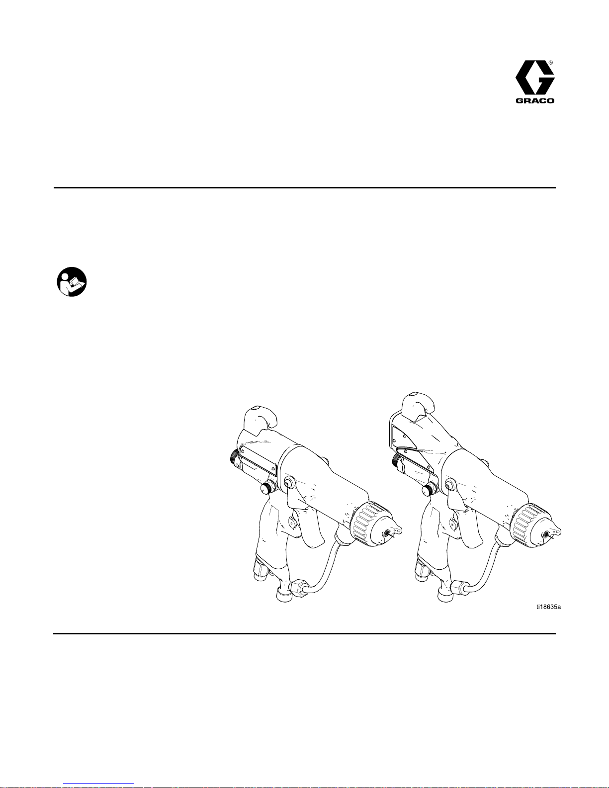
Pro Pro
Pro
Xp™ Xp™
Xp™
Electrostatic Electrostatic
Electrostatic
Air Air
Air
Spray Spray
Spray
Gun Gun
Gun
3A2494D
EN
For For
For
use use
use
in ininClass Class
Class
I, I,I,Div. Div.
Div.
I IIHazardous Hazardous
Hazardous
Locations Locations
Locations
using using
using
Group Group
Group
D DDspray spray
spray
materials. materials.
materials.
For For
For
use use
use
in in
in
Group Group
Group
II, II,
II,
Zone Zone
Zone
1 11Explosive Explosive
Explosive
Atmosphere Atmosphere
Atmosphere
Locations Locations
Locations
using using
using
Group Group
Group
IIA IIA
IIA
spray spray
spray
materials. materials.
materials.
For For
For
professional professional
professional
use use
use
only. only.
only.
Important Important
Important
Safety Safety
Safety
Instructions Instructions
Instructions
Readallwarningsandinstructionsinthismanual.
Save Save
Save
these these
these
instructions. instructions.
instructions.
100 psi (0.7 MPa, 7.0 bar) Maximum
Fluid Working Pressure
100 psi (0.7 MPa, 7.0 bar) Maximum Air
Working Pressure
See See
See
page page
page
3 33for for
for
model model
model
part part
part
numbers numbers
numbers
and and
and
approval approval
approval
information. information.
information.
PROVENQUALITY.LEADINGTECHNOLOGY.
Page 2

Contents Contents
Contents
Models...............................................................3
Warnings...........................................................4
GunOverview....................................................7
HowtheElectrostaticSprayGun
Works............................................7
Controls,Indicators,andComponents...........8
SmartGuns.................................................9
Installation..........................................................15
WarningSign...............................................15
VentilatetheSprayBooth.............................15
AirSupplyLine............................................16
FluidSupplyLine.........................................16
GunSetup..........................................................18
GunSetupChecklist....................................18
Grounding...................................................21
CheckGunElectricalGrounding...................25
CheckFluidResistivity.................................26
CheckFluidViscosity...................................26
FlushBeforeUsingEquipment......................26
GuidelinesforAbrasiveMaterials..................26
Operation...........................................................27
PressureReliefProcedure............................27
Startup........................................................27
Shutdown....................................................27
Maintenance......................................................28
Flushing......................................................28
CleantheGunDaily.....................................29
DailySystemCare.......................................30
ElectricalTests...................................................31
TestGunResistance....................................31
TestPowerSupplyResistance.....................32
TestElectrodeResistance............................32
Troubleshooting..................................................33
SprayPatternTroubleshooting......................33
GunOperationTroubleshooting....................34
ElectricalTroubleshooting............................35
Repair................................................................37
PreparetheGunforService.........................37
AirCapandNozzleReplacement..................38
ElectrodeReplacement................................39
FluidPackingRodRemoval..........................40
PackingRodRepair.....................................40
BarrelRemoval............................................42
BarrelInstallation.........................................42
PowerSupplyRemovaland
Replacement..................................43
AlternatorRemovalandReplacement...........44
FluidTubeRemovalandReplacement...........46
FanAirAdjustmentValveRepair..................47
AtomizingAirRestrictorValveRepair............48
ESOn-OffandFluidAdjustmentValve
Repair............................................49
AirValveRepair...........................................50
SmartModuleReplacement..........................51
AirSwivelandExhaustValve
Replacement..................................52
Parts..................................................................53
StandardAirSprayGunAssembly................53
RoundSprayAssembly................................55
StandardHighConductivityAirSprayGun
Assembly.......................................56
SmartHighConductivityAirSprayGun
Assembly.......................................58
SmartAirSprayGunAssembly.....................60
PackingRodAssembly.................................62
AlternatorAssembly.....................................63
ESOn-OffandFluidAdjustmentValve...........64
FanAirAdjustmentValveAssembly..............65
AtomizingAirRestrictorValve
Assembly.......................................65
SmartModuleAssembly...............................66
HighConductivityFluidTube
Assembly.......................................67
AirCapsandFluidNozzles.................................68
FluidNozzleSelectionChart.........................68
FluidNozzlePerformanceCharts..................68
AirCapSelectionChart................................70
AirConsumptionCharts...............................71
RepairKits,RelatedManuals,and
Accessories..........................................73
GunAccessories..........................................73
OperatorAccessories...................................74
SystemAccessories.....................................74
TestEquipment...........................................74
Hoses.........................................................75
Dimensions........................................................76
TechnicalData...................................................77
GracoProXpWarranty.......................................78
2
3A2494D
Page 3
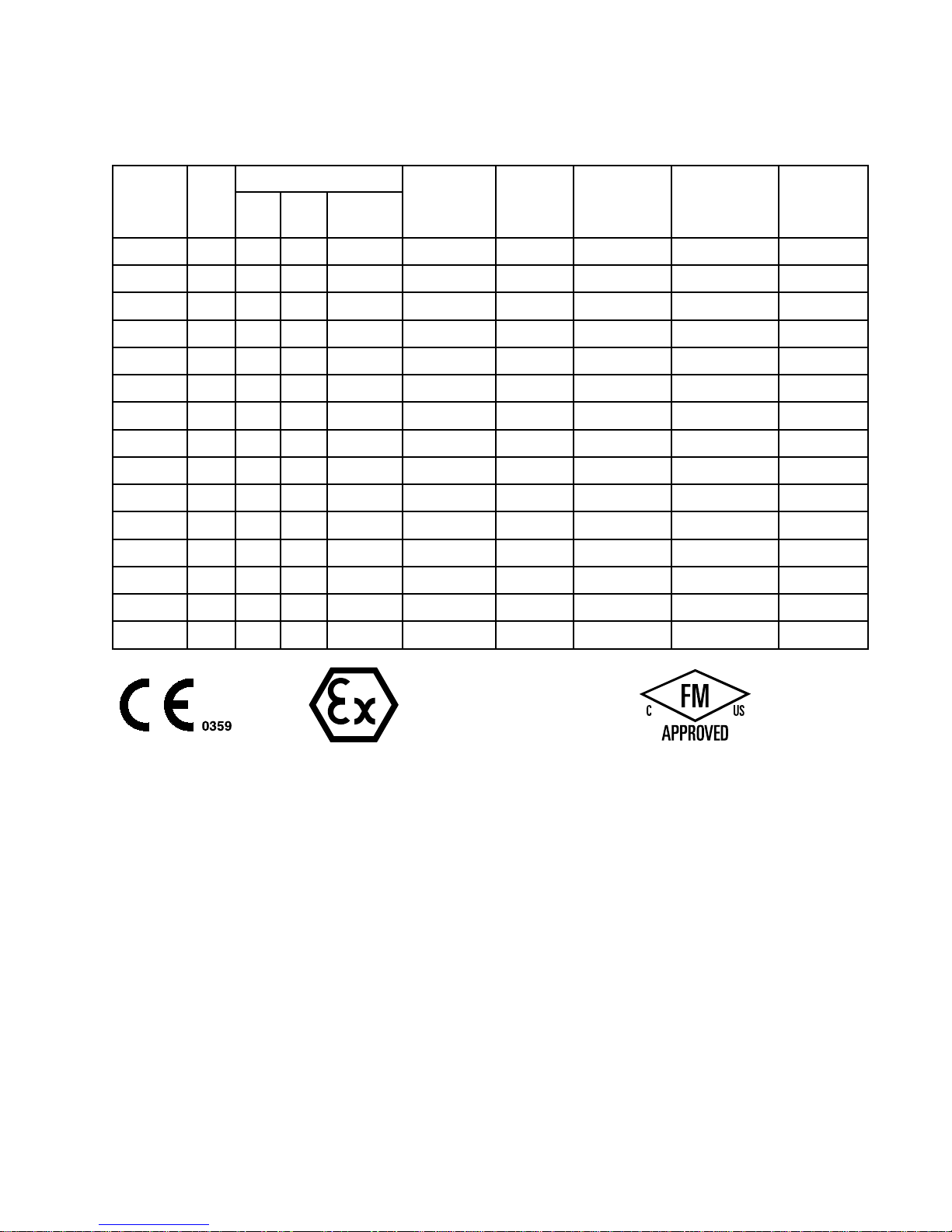
Models
Models Models
Models
Nozzle Nozzle
Nozzle
Part Part
Part
No. No.
No.
kV kV
kV
1.5 1.5
1.5
mm mm
mm
1.2 1.2
1.2
mm mm
mm
Round Round
Round
Spray Spray
Spray
Standard Standard
Standard
Display Display
Display
Smart Smart
Smart
Display Display
Display
Standard Standard
Standard
Coatings Coatings
Coatings
High High
High
Conductivity/ Conductivity/
Conductivity/
High High
High
Wear Wear
Wear
Increased Increased
Increased
Transfer Transfer
Transfer
Efciency Efciency
Efciency
L40T1040
✔✔✔
L40T1440
✔✔✔✔
L40T1540
✔✔✔✔
L40T1640
✔✔✔
L60T1060
✔✔✔
L60T1160
✔✔✔
L60T1260
✔✔✔
L60T1660
✔✔✔
L60M1060
✔✔✔
L60M1260
✔✔✔
L60M1660
✔✔✔
L85T1085
✔✔✔
L85T1685
✔✔✔
L85M1085
✔✔✔
L85M1685
✔✔✔
II IIII2 22G G
G
EEx0.24mJT6
FM12ATEX0068
EN50050
Ta0°C–50°C
3A2494D 3
Page 4
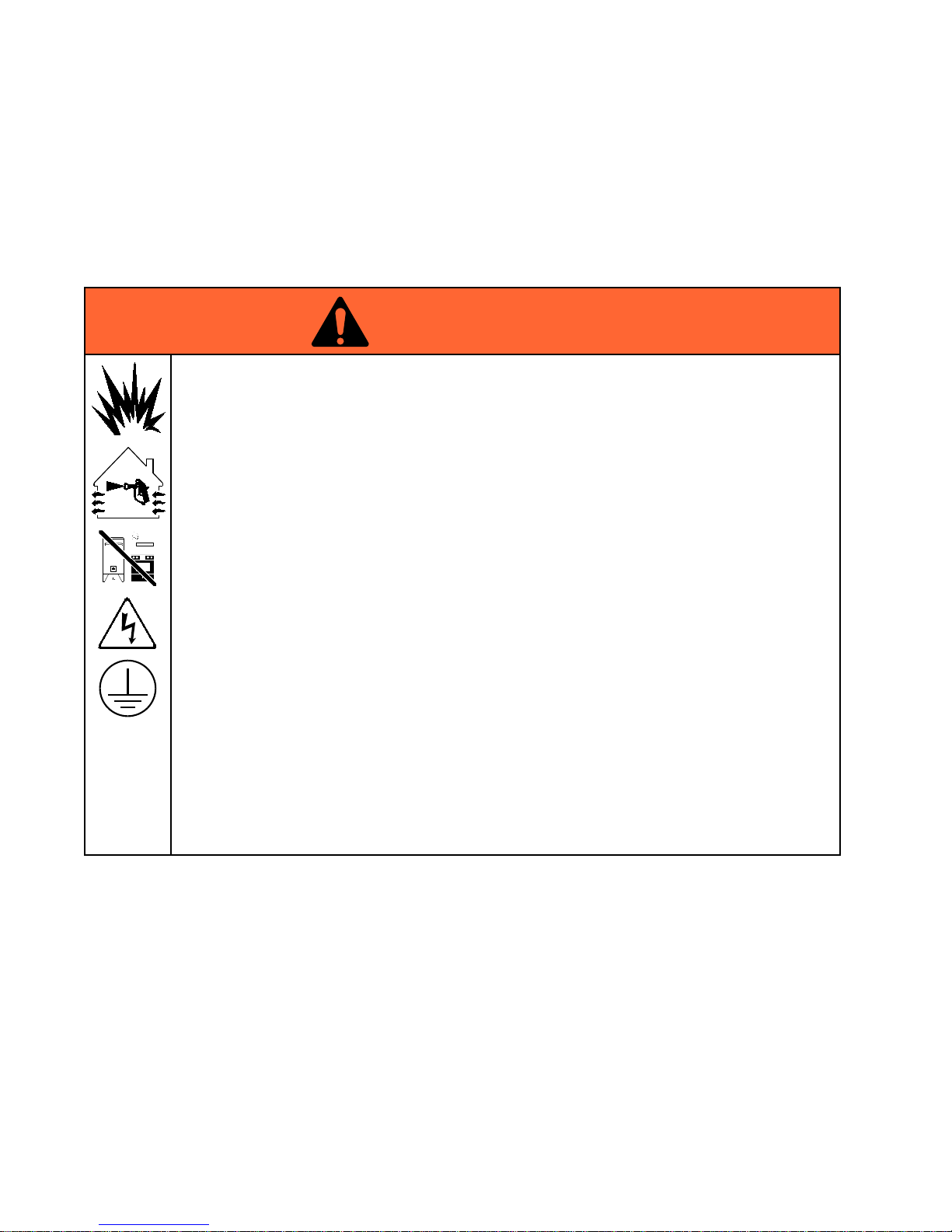
Warnings
Warnings Warnings
Warnings
Thefollowingwarningsareforthesetup,use,grounding,maintenance,andrepairofthisequipment.The
exclamationpointsymbolalertsyoutoageneralwarningandthehazardsymbolsrefertoprocedure-specic
risks.Whenthesesymbolsappearinthebodyofthismanualoronwarninglabels,referbacktothese
Warnings.Product-specichazardsymbolsandwarningsnotcoveredinthissectionmayappearthroughout
thebodyofthismanualwhereapplicable.
WARNING WARNING
WARNING
FIRE, FIRE,
FIRE,
EXPLOSION, EXPLOSION,
EXPLOSION,
AND AND
AND
ELECTRIC ELECTRIC
ELECTRIC
SHOCK SHOCK
SHOCK
HAZARD HAZARD
HAZARD
Flammablefumes,suchassolventandpaintfumes,inwork work
work
area area
area
canigniteorexplode.Tohelp
preventre,explosion,andelectricshock:
•Electrostaticequipmentmustbeusedonlybytrained,qualiedpersonnelwhounderstand
therequirementsofthismanual.
•Groundallequipment,personnel,objectbeingsprayed,andconductiveobjectsinorcloseto
sprayarea.Resistancemustnotexceed1megohm.SeeGrounding Grounding
Grounding
instructions.
•OnlyusegroundedGracoconductiveairsupplyhoses.
•Donotusepaillinersunlesstheyareconductiveandgrounded.
•Stop Stop
Stop
operation operation
operation
immediately immediately
immediately
ifstaticsparkingoccursoryoufeelashock.Donotuse
equipmentuntilyouidentifyandcorrecttheproblem.
•Checkgunresistance,hoseresistance,andelectricalgroundingdaily.
•Useandcleanequipmentonlyinwellventilatedarea.
•Interlockthegunairsupplytopreventoperationunlessventilatingfansareon.
•Usecleaningsolventswithhighestpossibleashpointwhenushingorcleaningequipment.
•Tocleantheexterioroftheequipment,cleaningsolventsmusthaveaashpointatleast
5°Caboveambienttemperature.
•Alwaysturntheelectrostaticsoffwhenushing,cleaningorservicingequipment.
•Eliminateallignitionsources;suchaspilotlights,cigarettes,portableelectriclamps,and
plasticdropcloths(potentialstaticarc).
•Donotplugorunplugpowercordsorturnlightsonoroffwhenammablefumesarepresent.
•Keepsprayareafreeofdebris,includingsolvent,ragsandgasoline.
•Keepaworkingreextinguisherintheworkarea.
4
3A2494D
Page 5
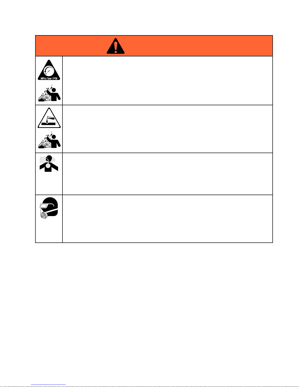
Warnings
WARNING WARNING
WARNING
PRESSURIZED PRESSURIZED
PRESSURIZED
EQUIPMENT EQUIPMENT
EQUIPMENT
HAZARD HAZARD
HAZARD
Fluidfromtheequipment,leaks,orrupturedcomponentscansplashintheeyesoronskin
andcauseseriousinjury.
•FollowthePressure Pressure
Pressure
Relief Relief
Relief
Procedure Procedure
Procedure
whenyoustopspraying/dispensingandbefore
cleaning,checking,orservicingequipment.
•Tightenalluidconnectionsbeforeoperatingtheequipment.
•Checkhoses,tubes,andcouplingsdaily.Replacewornordamagedpartsimmediately.
PLASTIC PLASTIC
PLASTIC
PARTS PARTS
PARTS
CLEANING CLEANING
CLEANING
SOLVENT SOLVENT
SOLVENT
HAZARD HAZARD
HAZARD
Manysolventscandegradeplasticpartsandcausethemtofail,whichcouldcauseserious
injuryorpropertydamage.
•Useonlycompatiblewater-basedsolventstocleanplasticstructuralorpressure-containing
parts.
•SeeTechnical Technical
Technical
Data Data
Data
inthisandallotherequipmentinstructionmanuals.Readuidand
solventmanufacturer’sMSDSsandrecommendations.
TOXIC TOXIC
TOXIC
FLUID FLUID
FLUID
OR OR
OR
FUMES FUMES
FUMES
Toxicuidsorfumescancauseseriousinjuryordeathifsplashedintheeyesoronskin,
inhaled,orswallowed.
•ReadMSDS’stoknowthespecichazardsoftheuidsyouareusing.
•Storehazardousuidinapprovedcontainers,anddisposeofitaccordingtoapplicable
guidelines.
PERSONAL PERSONAL
PERSONAL
PROTECTIVE PROTECTIVE
PROTECTIVE
EQUIPMENT EQUIPMENT
EQUIPMENT
Wearappropriateprotectiveequipmentwhenintheworkareatohelppreventseriousinjury,
includingeyeinjury,hearingloss,inhalationoftoxicfumes,andburns.Thisprotective
equipmentincludesbutisnotlimitedto:
•Protectiveeyewear,andhearingprotection.
•Respirators,protectiveclothing,andglovesasrecommendedbytheuidandsolvent
manufacturer.
3A2494D 5
Page 6
Warnings
WARNING WARNING
WARNING
EQUIPMENT EQUIPMENT
EQUIPMENT
MISUSE MISUSE
MISUSE
HAZARD HAZARD
HAZARD
Misusecancausedeathorseriousinjury.
•Donotoperatetheunitwhenfatiguedorundertheinuenceofdrugsoralcohol.
•Donotexceedthemaximumworkingpressureortemperatureratingofthelowestrated
systemcomponent.SeeTechnical Technical
Technical
Data Data
Data
inallequipmentmanuals.
•Useuidsandsolventsthatarecompatiblewithequipmentwettedparts.SeeTechnical Technical
Technical
Data Data
Data
inallequipmentmanuals.Readuidandsolventmanufacturer’swarnings.Forcomplete
informationaboutyourmaterial,requestMSDSfromdistributororretailer.
•Donotleavetheworkareawhileequipmentisenergizedorunderpressure.
•TurnoffallequipmentandfollowthePressure Pressure
Pressure
Relief Relief
Relief
Procedure Procedure
Procedure
whenequipmentisnotinuse.
•Checkequipmentdaily.Repairorreplacewornordamagedpartsimmediatelywithgenuine
manufacturer’sreplacementpartsonly.
•Donotalterormodifyequipment.Alterationsormodicationsmayvoidagencyapprovals
andcreatesafetyhazards.
•Makesureallequipmentisratedandapprovedfortheenvironmentinwhichyouareusingit.
•Useequipmentonlyforitsintendedpurpose.Callyourdistributorforinformation.
•Routehosesandcablesawayfromtrafcareas,sharpedges,movingparts,andhotsurfaces.
•Donotkinkoroverbendhosesorusehosestopullequipment.
•Keepchildrenandanimalsawayfromworkarea.
•Complywithallapplicablesafetyregulations.
6 3A2494D
Page 7

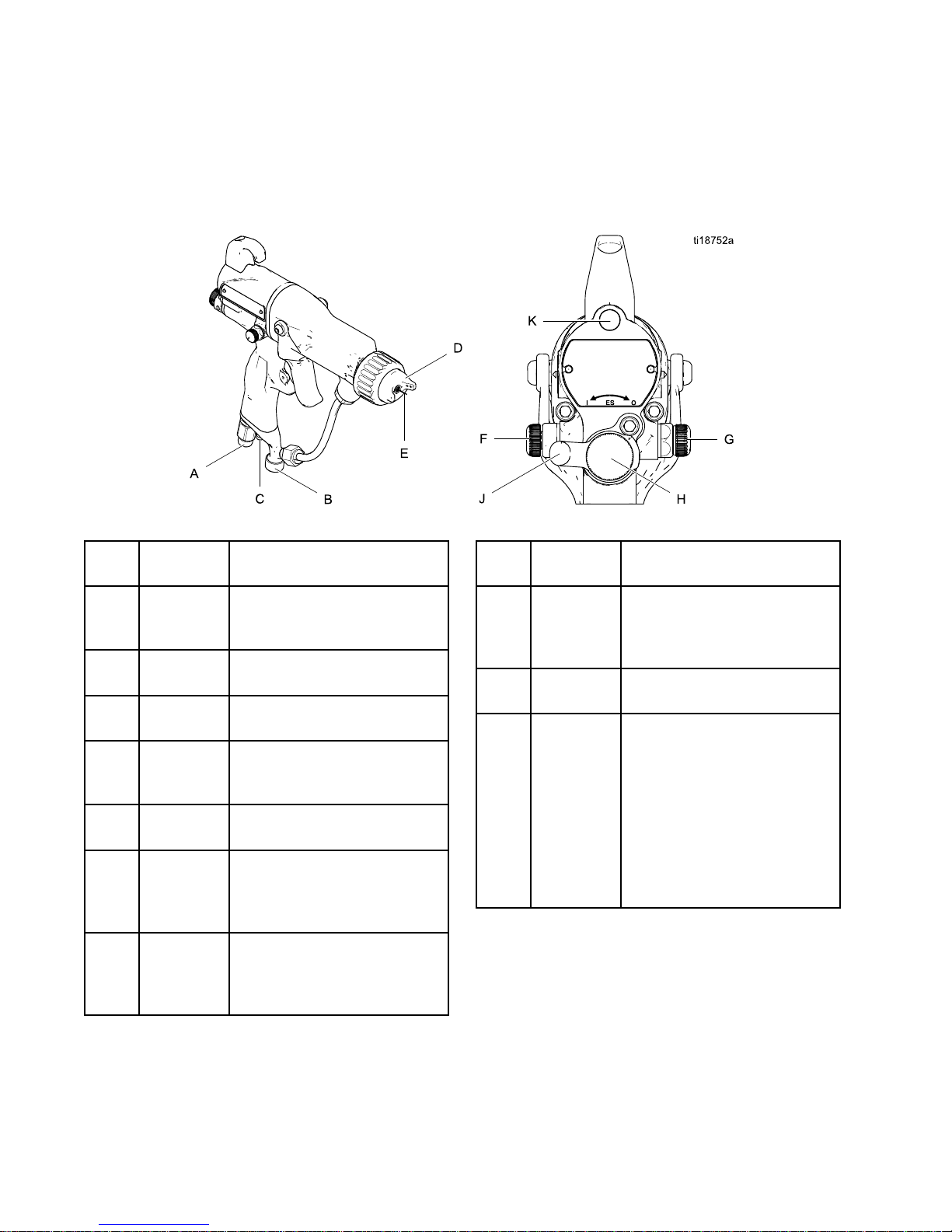
GunOverview
Gun Gun
Gun
Overview Overview
Overview
How How
How
the the
the
Electrostatic Electrostatic
Electrostatic
Spray Spray
Spray
Gun Gun
Gun
Works Works
Works
Theairhosesuppliesairtothespraygun.Partof
theairoperatesthealternatorturbineandtherest
oftheairatomizestheuidbeingsprayed.The
alternatorgeneratespower,whichisconvertedby
thepowercartridgetosupplyhighvoltagetothe
gun’selectrode.
Thepumpsuppliesuidtotheuidhoseandgun,
wheretheuidiselectrostaticallychargedasit
passestheelectrode.Thechargeduidisattracted
tothegroundedworkpiece,wrappingaroundand
evenlycoatingallsurfaces.
3A2494D
7
Page 8
GunOverview
Controls, Controls,
Controls,
Indicators, Indicators,
Indicators,
and and
and
Components Components
Components
Theelectrostaticgunincludesthefollowing
controls,indicators,andcomponents(seeFig.
1).ForinformationonSmartguns,alsosee
SmartGuns,page9.
Figure1GunOverview
Item Item
Item
Descrip- Descrip-
Description tion
tion
Purpose Purpose
Purpose
A
AirSwivel
Inlet
1/4npsm(m)left-handthread,
forGracogroundedairsupply
hose.
BFluidInlet
3/8npsm(m),foruidsupply
hose.
C
TurbineAir
Exhaust
Barbedtting,forsupplied
exhausttube.
D
AirCap
and
Nozzle
SeeAirCapsandFluid
Nozzles,page68,foravail-
ablesizes.
EElectrode
Needle
Supplieselectrostaticcharge
totheuid.
FFanAir
Adjustment
Valve
Adjustsfansizeandshape.
Canbeusedtodecrease
patternwidth.
G
Atomizing
Air
Restrictor
Valve
Restrictsaircapairow.
Replacewithplug(included)
ifdesired.
Item Item
Item
Descrip- Descrip-
Description tion
tion
Purpose Purpose
Purpose
HFluidAd-
justment
Knob
Adjustsuidowbylimiting
uidneedletravel.Useonly
inlowowconditions,to
reducewear.
J
ESOn-Off
Valve
TurnselectrostaticsON(I)or
OFF(O).
K
ESIndicator(standardgun
only;for
Smartgun
indicator,see
Operating
Mode,
page9)
LitwhenESisON(I).Colorindicatesalternatorfrequency.
SeetheLEDindicatortable
intheGunSetupChecklist,
page18.
8 3A2494D
Page 9
GunOverview
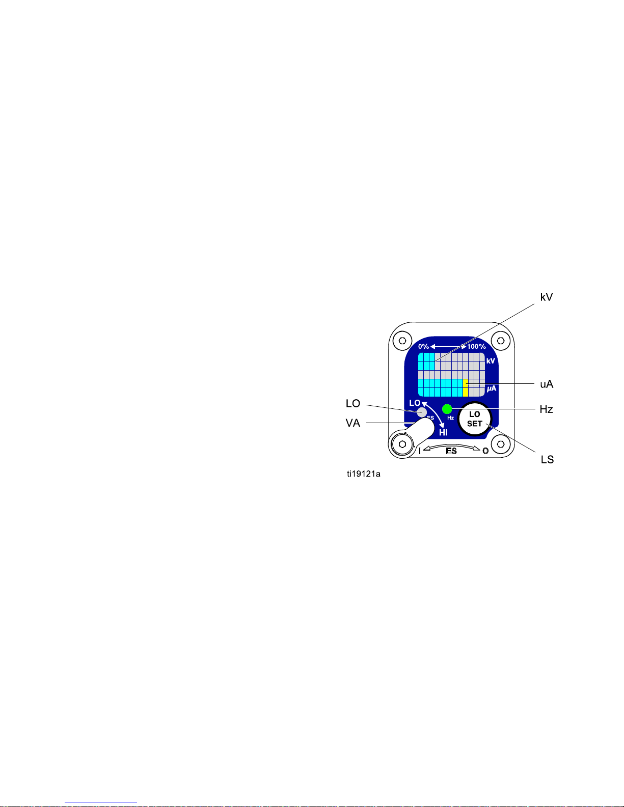
Smart Smart
Smart
Guns Guns
Guns
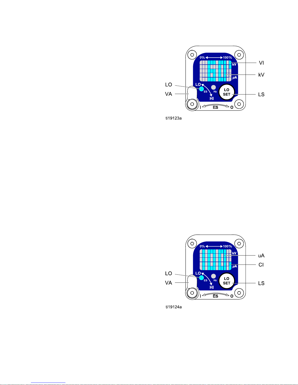
TheSmartGunmoduledisplayssprayingvoltage,
current,alternatorspeed,andthevoltagesetting(low
orhigh).Italsoallowstheusertochangetoalower
sprayingvoltage.Themodulehastwomodes:
•OperatingMode
•DiagnosticMode
Operating Operating
Operating
Mode Mode
Mode
Bar Bar
Bar
Graph Graph
Graph
SeeFig.2,andTable1onpage10.TheOperating
Modedisplaysgundataduringnormalspraying.The
displayusesabargraphtoshowthevoltagelevelin
kiloVolts(kV)andthecurrentlevelinmicroAmperes
(uA).Thebargraphrangeisfrom0to100%foreach
value.
IfthebargraphLEDsareblue,thegunisreadyto
spray.IftheLEDsareyelloworred,thecurrentis
toohigh.Theuidmaybetooconductive,orsee
ElectricalTroubleshooting,page35forotherpossible
causes.
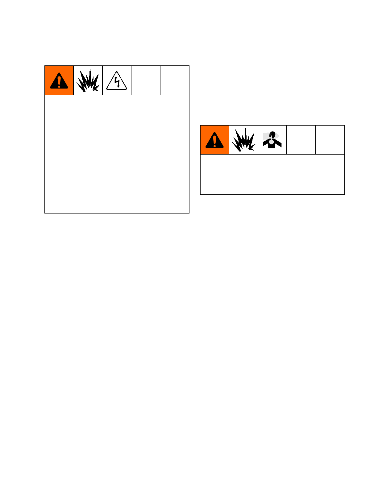
Hz Hz
Hz
Indicator Indicator
Indicator
TheHzindicatorfunctionsthesameastheES
indicatoronstandardguns.Theindicatorlightsto
showthealternatorspeedstatus,andhasthree
colors:
•Greenindicatesthealternatorspeediscorrect.
•Iftheindicatorchangestoamberafter1second,
increasetheairpressure.
•Iftheindicatorchangestoredafter1second,
reducetheairpressure.
Voltage Voltage
Voltage
Adjustment Adjustment
Adjustment
Switch Switch
Switch
Thevoltageadjustmentswitch(VA)allowsthe
operatortochangefromlowtohighvoltage.
•Thehighvoltagesettingisdeterminedbythe
maximumvoltageofthegunandisnotadjustable.
•Thelowvoltageindicator(LO)lights
whentheswitchissettoLO.Thelow
voltagesettingisuseradjustable.See
AdjustingtheLowVoltageSetting,page10.
NOTE: NOTE:
NOTE:
IftheErrordisplayappears,theSmartmodule
haslostcommunicationwiththepowersupply.See
ErrorDisplay,page10,forfurtherinformation.
Figure2SmartGunModuleinOperatingMode
3A2494D 9
Page 10
GunOverview
Error Error
Error
Display Display
Display
IftheSmartmodulelosescommunicationwith
thepowersupply,theErrordisplayappears,the
Hzindicatorturnsred,andtheSmartmoduleis
disabled.SeeFig.3,andTable1onpage10.
ThiscanoccurinOperatingModeorDiagnostic
Mode.SeeElectricalTroubleshooting,page35.
CommunicationmustberestoredtomaketheSmart
modulefunctional.
NOTE: NOTE:
NOTE:
Ittakes8secondsfortheErrordisplayto
appear.Ifthegunhasbeendisassembled,wait8
secondsbeforesprayingtoensurethatanError
conditionhasnotoccurred.
NOTE: NOTE:
NOTE:
Ifthereisnopowertothegun,theError
displaywillnotappear.
Figure3ErrorDisplay
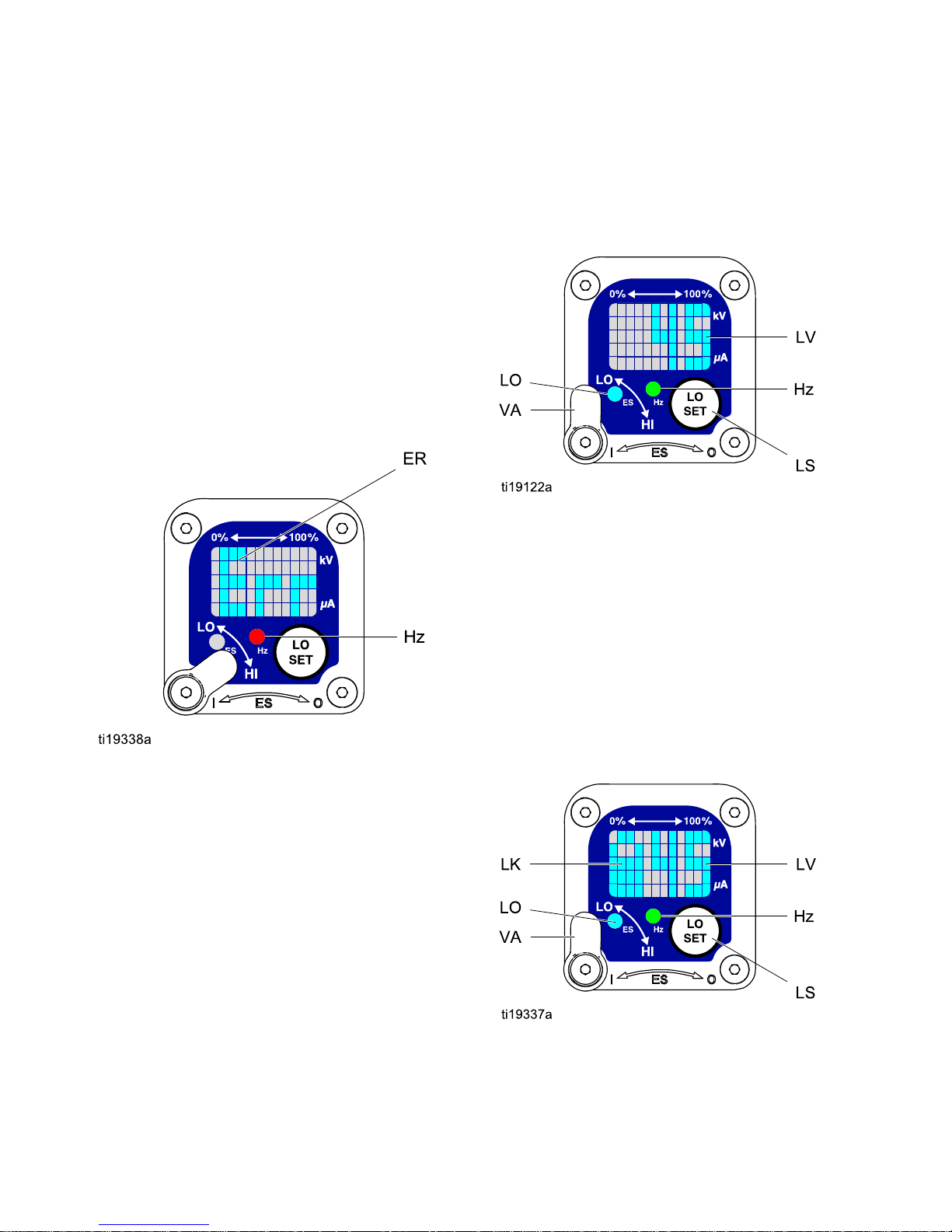
Adjusting Adjusting
Adjusting
the the
the
Low Low
Low
Voltage Voltage
Voltage
Setting Setting
Setting
Thelowvoltagesettingisuseradjustable.Toaccess
thelowvoltagesettingscreenwheninOperating
Mode,presstheLOSETbutton(LS)momentarily.
Thescreenwilldisplaythecurrentlowvoltage
setting.SeeFig.4,andTable1onpage10.The
possiblerangesare:
•85kVguns:40–85kV
•60kVguns:30–60kV
SettheVoltageAdjustmentswitch(VA)toLO.Press
theLOSETbuttonrepeatedlytoincreasethesetting
inincrementsof5.Whenthedisplayreachesthe
maximumsettingitwillreturntotheminimumsetting
foryourgun.Continuepressingthebuttonuntilyou
reachthedesiredsetting.
NOTE: NOTE:
NOTE:
After2secondsofinactivitythedisplaywill
returntotheOperatingScreen.
NOTE: NOTE:
NOTE:
Thelowvoltagesettingmaybelocked.See
LockSymbol,page10.
Figure4LowVoltageSettingScreen(Unlocked)
Lock Lock
Lock
Symbol Symbol
Symbol
Thelowvoltagesettingmaybelocked.Whenlocked,
animage(LK)appearsonthescreen.SeeFig.5,
andTable1onpage10.
•WheninHImode,thelowvoltagesettingisalways always
always
locked.ThelocksymbolwillappearwhentheLO
SETbuttonispressed.
•WheninLOmode,thelocksymbolwill
only only
only
appearifthelockisenabled.See
LowVoltageLockScreen,page14,tolockor
unlockthelowvoltagesetting.
Figure5LowVoltageSettingScreen(Locked)
10 3A2494D
Page 11

GunOverview
Table Table
Table
1 11. ..Key Key
Key
for for
for
Figs. Figs.
Figs.
2–9. 2–9.
2–9.
Item Item
Item
Description Description
Description
Purpose Purpose
Purpose
VA
VoltageAdjustmentSwitch
Two-positionswitchsetssmart
gunvoltagetolowsetting(LO)or
highsetting(HI).Thisswitchis
functionalinOperatingModeand
inDiagnosticMode.
LO
LowVoltageModeIndicator
Lights(blue)whenthesmartgun
issettoLowVoltage.
kV
Voltage(kV)Display
Displaysactualsprayingvoltage
ofthegun,inkV.InOperating
Mode,displayisabargraph.
InDiagnosticMode,voltageis
displayedasanumber.
uA
Current(uA)Display
Displaysactualsprayingcurrent
ofthegun,inuA.InOperating
Mode,displayisabargraph.
InDiagnosticMode,currentis
displayedasanumber.
LSLOSETbutton
Pressmomentarilytoenterthe
LowVoltageSettingscreen.
Pressandholdforapproximately5
secondstoenterorexitDiagnostic
Mode.
WhileinDiagnosticMode,press
momentarilytoadvancethrough
screens.
WhileontheLowVoltageLock
Screen(inDiagnosticMode),
pressandholdtoturnthelockon
oroff.
LVLowVoltageDisplayDisplaysthelowvoltagesetting
asanumber.Thesettingcanbe
changed.SeeFig.4.
LKLowVoltageLocked
Appearsifthelowvoltagesetting
islocked.SeeFig.5andFig.9.
3A2494D
11
Page 12

GunOverview
Item Item
Item
Description Description
Description
Purpose Purpose
Purpose
LD
LODisplay
AppearsontheLowVoltageLock
Screen.SeeFig.9.
ERErrorDisplay
AppearsiftheSmartmoduleloses
communicationwiththepower
supply.SeeFig.3.
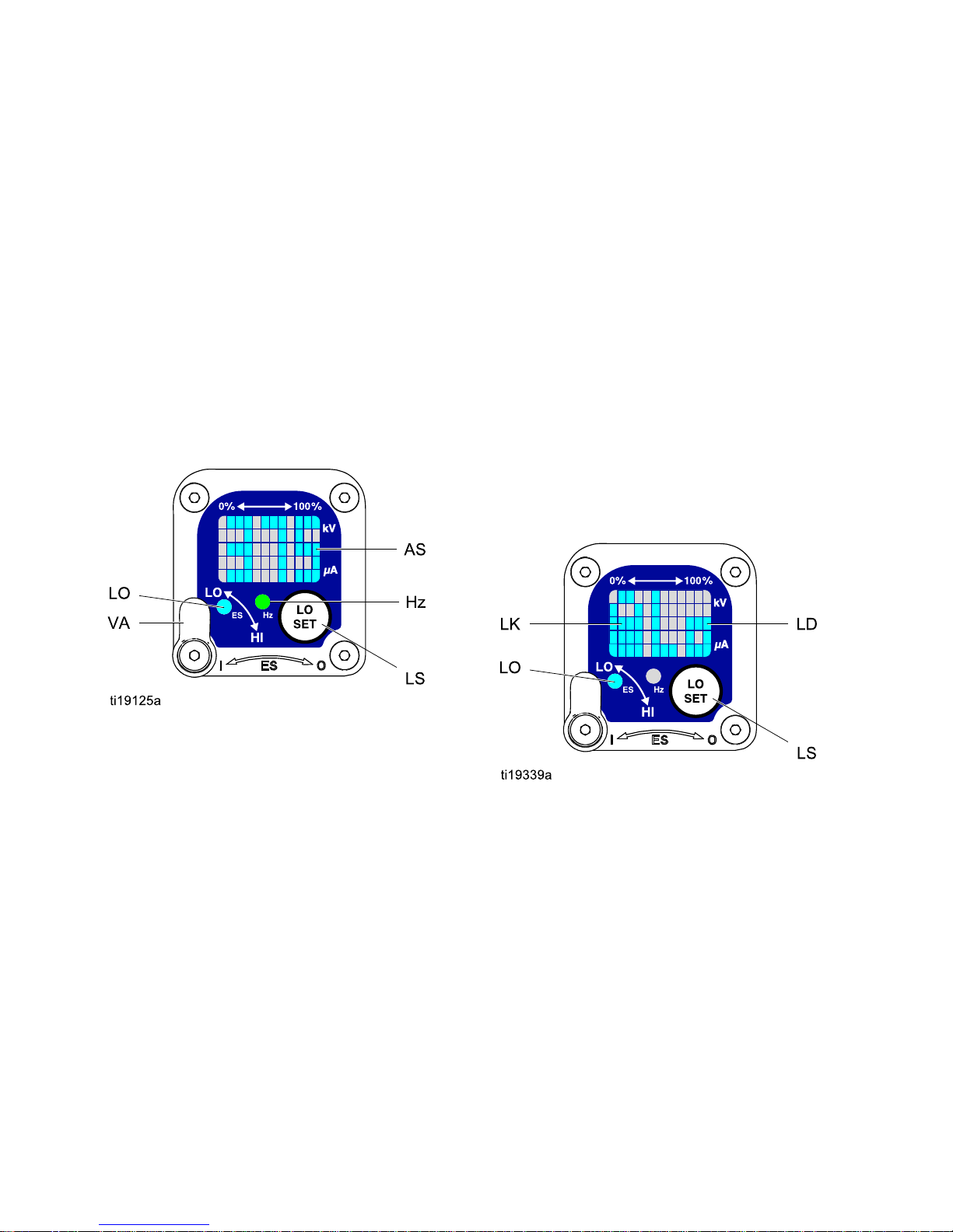
VIVoltageIndicatorInDiagnosticMode,thetwotop
rightLEDsofthescreenlight,
indicatingthatthevaluedisplayed
isinkV.SeeFig.6.
CICurrentIndicator
InDiagnosticMode,thetwo
bottomrightLEDsofthescreen
light,indicatingthatthevalue
displayedisinuA.SeeFig.7.
ASAlternatorSpeedDisplay
InDiagnosticMode,Hzlevelis
displayedasanumber.SeeFig.
8.
Hz
AlternatorSpeedIndicatorInOperatingMode,indicatorcolor
variestoshowthealternator
speedstatus:
•greenindicatesthealternator
speedisatthecorrectlevel.
•Iftheindicatorchangestoamber
after1second,thealternator
speedistoolow.
•Iftheindicatorchangestored
after1second,thealternator
speedistoohigh.Theindicator
willalsoturnrediftheError
displayappears.
InDiagnosticMode,theindicator
isgreenwhenintheAlternator
Speed(Hertz)screen.
12
3A2494D
Page 13
GunOverview
Diagnostic Diagnostic
Diagnostic
Mode Mode
Mode
DiagnosticModeincludesfourscreenswhichdisplay
gundata:
•Voltage(kiloVolts)Screen
•Current(microAmperes)Screen
•AlternatorSpeed(Hertz)Screen
•LowVoltageLockScreen
NOTE: NOTE:
NOTE:
YoumustbeinOperatingModetoadjustthe
lowvoltagesetting;thesettingisnotadjustablein
DiagnosticMode.However,thevoltageadjustment
switch(VA)canbesettoHIorLOinOperatingMode
andinDiagnosticMode.
ToenterDiagnosticMode,pressandholdtheLOSET
(LS)buttonforapproximately5seconds.Thedisplay
willgototheVoltage(kiloVolts)Screen,page13.
Toadvancetothenextscreen,presstheLOSET
buttonagain.
ToexitDiagnosticMode,pressandholdtheLOSET
buttonforapproximately5seconds.Thescreenwill
returntoOperatingMode.
NOTE: NOTE:
NOTE:
IfthegunisdetriggeredwhileinDiagnostic
Mode,thelastscreenviewedwillbedisplayedwhen
thegunisretriggered.
NOTE: NOTE:
NOTE:
DiagnosticModecannotbeexited
fromtheLowVoltageLockScreen.See
LowVoltageLockScreen,page14fordetails.
Voltage Voltage
Voltage
(kiloVolts) (kiloVolts)
(kiloVolts)
Screen Screen
Screen
TheVoltage(kiloVolts)Screenistherstscreento
appearafterenteringDiagnosticMode.SeeFig.6,
andTable1onpage10.Toenterthisscreen,press
andholdtheLOSETbuttonforapproximately5
secondswhileintheOperatingMode.
Thisscreendisplaysthesprayingvoltageofthe
gunasanumber(kV),roundedtothenearest5kV.
ThetwotoprightLEDs(VI)ofthedisplaypanel
light,indicatingthattheVoltage(kiloVolts)Screen
isdisplayed.Thedisplayisareadoutandcannot
bechanged.
PresstheLOSETbuttontoadvancetothe
Current(microAmperes)Screen,page13.Press
andholdforapproximately5secondstoreturnto
OperatingMode.
Figure6Voltage(kiloVolts)Screen
Current Current
Current
(microAmperes) (microAmperes)
(microAmperes)
Screen Screen
Screen
TheCurrent(microAmperes)Screenisthesecond
screenintheDiagnosticMode.SeeFig.7,andTable
1onpage10.Toenterthisscreen,presstheLO
SETbuttonwhileintheVoltage(kiloVolts)Screen.
Thisscreendisplaysthesprayingcurrentofthegun
asanumber(uA),roundedtothenearest5uA.The
twobottomrightLEDs(CI)ofthedisplaypanellight,
indicatingthattheCurrent(microAmperes)Screen
isdisplayed.Thedisplayisareadoutandcannot
bechanged.
PresstheLOSETbuttontoadvancetothe
AlternatorSpeed(Hertz)Screen,page14.Press
andholdforapproximately5secondstoreturnto
OperatingMode.
Figure7Current(microAmperes)Screen
3A2494D 13
Page 14
GunOverview
Alternator Alternator
Alternator
Speed Speed
Speed
(Hertz) (Hertz)
(Hertz)
Screen Screen
Screen
TheAlternatorSpeed(Hertz)Screenisthethird
screenintheDiagnosticMode.SeeFig.8,andTable
1onpage10.Toenterthisscreen,presstheLOSET
buttonwhileintheCurrent(microAmperes)Screen.
Thisscreendisplaysthealternatorspeedasa3digit
number(AS),roundedtothenearest10Hz.The
displayisareadoutandcannotbechanged.Ifthe
alternatorspeedisgreaterthan999Hz,thedisplay
willshow999.
TheHzindicatorlightsgreentoshowthatyouare
viewingtheAlternatorSpeed(Hertz)Screen.
PresstheLOSETbuttontoadvancetothe
LowVoltageLockScreen,page14.Pressandhold
forapproximately5secondstoreturntoOperating
Mode.
Figure8AlternatorSpeed(Hertz)Screen
Low Low
Low
Voltage Voltage
Voltage
Lock Lock
Lock
Screen Screen
Screen
TheLowVoltageLockScreenisthefourthscreenin
theDiagnosticMode.SeeFig.9,andTable1on
page10.Toenterthisscreen,presstheLOSET
buttonwhileintheAlternatorSpeed(Hertz)Screen.
ThisscreendisplaysthestatusoftheLowVoltage
Lock.Ifthesettingislocked,thelockimage(LK)
appearstotheleftoftheLodisplay(LD).Ifthesetting
isunlocked,thelockimagedoesnotappear.
Tochangethelockstatus,pressandholdthe
LOSETbuttonuntilthelockimageappearsor
disappears.Ifthelockisset,theimagewillalso
appearontheLowVoltageSettingScreenwhenin
lowvoltagemode(seeFig.4).
NOTE: NOTE:
NOTE:
DiagnosticModecannotbeexitedfromthis
screen,becausepressingandholdingtheLOSET
buttonisusedtoturnthelockonoroff.Toexit,
pressLOSETmomentarilytoreturntotheVoltage
(kiloVolts)Screen,thenexitDiagnosticModefrom
there.
Figure9LowVoltageLockScreen
14
3A2494D
Page 15
Installation
Installation Installation
Installation
Installingandservicingthisequipmentrequires
accesstopartswhichmaycauseelectricshock
orotherseriousinjuryifworkisnotperformed
properly.
•Donotinstallorservicethisequipmentunless
youaretrainedandqualied.
•Besureyourinstallationcomplieswithlocal,
state,andnationalcodesfortheinstallation
ofelectricalapparatusinaClassI,Div.I,
HazardousLocationoraGroupII,ZoneI
ExplosiveAtmosphereLocation.
•Complywithallapplicablelocal,state,and
nationalre,electrical,andothersafety
regulations.
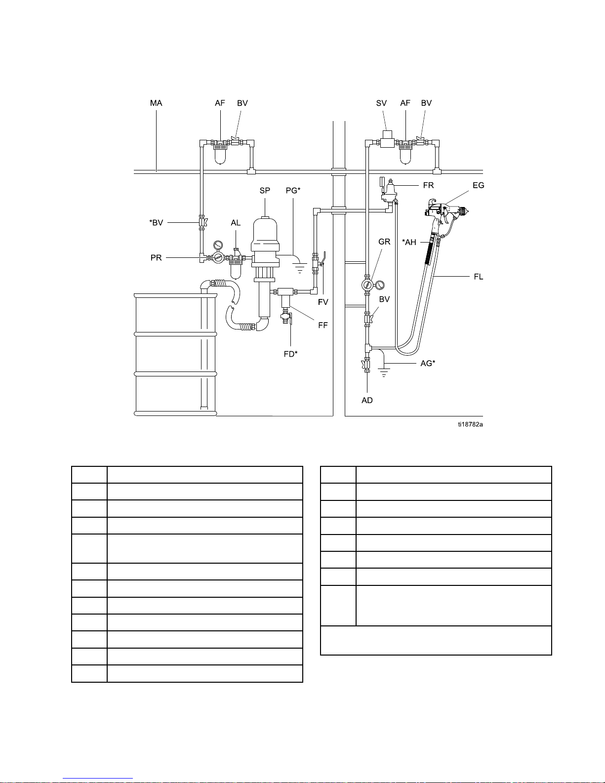
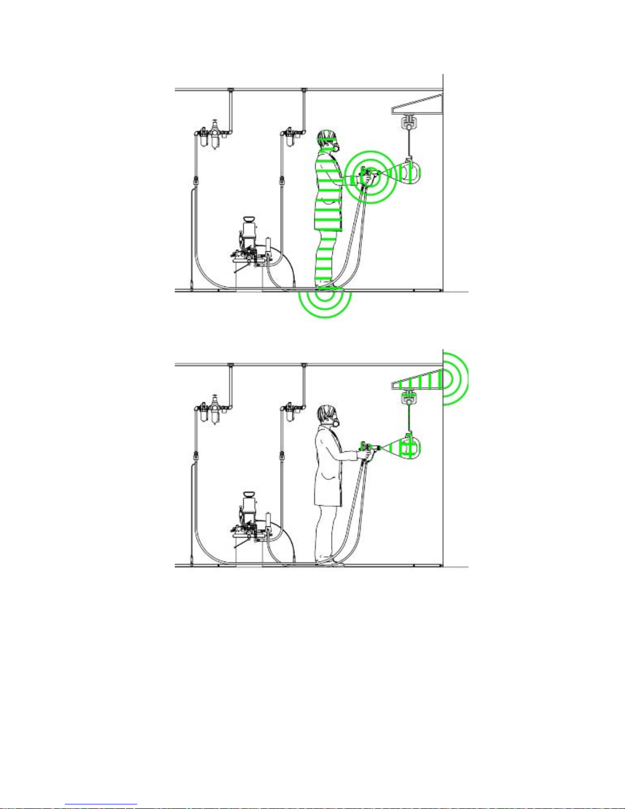
Fig.10showsatypicalelectrostaticairspraysystem.
Itisnotanactualsystemdesign.Forassistance
indesigningasystemtosuityourparticularneeds,
contactyourGracodistributor.
Warning Warning
Warning
Sign Sign
Sign
Mountwarningsignsinthesprayareawherethey
caneasilybeseenandreadbyalloperators.An
EnglishWarningSignisprovidedwiththegun.
Ventilate Ventilate
Ventilate
the the
the
Spray Spray
Spray
Booth Booth
Booth
Providefreshairventilationtoreducetheriskofre
orexplosioncausedbythebuildupofammableor
toxicvaporswhenspraying,ushing,orcleaning
thegun.Donotoperatethegununlessventilation
fansareoperating.
Electricallyinterlockthegunairsupplywiththe
ventilatorstopreventgunoperationwithout
ventilatingfansoperating.Checkandfollowalllocal,
state,andnationalcodesregardingairexhaust
velocityrequirements.
Highvelocityairexhaustwilldecreasetheoperating
efciencyoftheelectrostaticsystem.Airexhaust
velocityof100ft/min(31linearmeters/minute)should
besufcient.
3A2494D 15
Page 16
Installation
Air Air
Air
Supply Supply
Supply
Line Line
Line
Toreducetheriskofelectricshock,theairsupply
hosemustbeelectricallyconnectedtoatrueearth
ground.Use Use
Use
only only
only
Graco Graco
Graco
Grounded Grounded
Grounded
Air Air
Air
Supply Supply
Supply
Hose. Hose.
Hose.
1.SeeFig.10.UsetheGracoGroundedAirSupply
Hose(AH)tosupplyairtothegun.Thegunair
inletttinghasaleft-handthread.Theairsupply
hosegroundwire(AG)mustbeconnectedtoa
trueearthground.Donotconnecttheairsupply
hosetothegunairinletyet.
2.Installanairlinelter/waterseparator(AF)onthe
gunairlinetoensureadry,cleanairsupplytothe
gun.Dirtandmoisturecanruintheappearance
ofyournishedworkpieceandcancausethe
guntomalfunction.
3.Installbleed-typeairregulators(PR,GR)on
thepumpandgunairsupplylinestocontrolair
pressuretothepumpandgun.
Trappedaircancausethepumptocycle
unexpectedly,whichcanresultinserious
injury,includingsplashinguidintheeyesor
ontheskin.Donotoperatetheequipment
withoutthebleed-typeairvalve(BV)installed.
4.Installableed-typeairvalve(BV)onthepump
airsupplyline.Thebleed-typeairvalve(BV)is
requiredinyoursystemtoshutoffairtothepump
andrelieveairtrappedbetweenthevalveand
thepumpaftertheairregulatorisshutoff.Install
anadditionalbleed-typeairvalveonthemainair
line(MA)toisolatetheaccessoriesforservicing.
5.Installanairbleedvalve(BV)oneachgunair
supplylinetoshutoffairtothegun(s)andrelieve
airtrappedbetweenthevalveandthegunafter
theairregulatorisshutoff.
Fluid Fluid
Fluid
Supply Supply
Supply
Line Line
Line
1.Blowouttheuidline(FL)withairandushit
withsolvent.Usesolventwhichiscompatible
withtheuidtobesprayed.Donotconnectthe
uidsupplylinetothegunuidinletyet.
2.Installauidregulator(FR)ontheuidlineto
controluidpressuretothegun.
3.Installauidlter(FF)nearthepumpoutlet,to
removeparticlesandsedimentwhichcouldclog
thespraynozzle.
Toreducetheriskofseriousinjury,including
splashinguidintheeyesorontheskin,do
notoperateequipmentwithouttheuiddrain
valve(FD)installed.
4.Theuiddrainvalve(FD)isrequiredinyour
systemtoassistinrelievinguidpressureinthe
displacementpump,hose,andgun.Triggering
theguntorelievepressuremaynotbesufcient.
Installadrainvalveclosetothepump'suid
outlet.
16 3A2494D
Page 17
Installation
NON NON
NON
- --HAZARDOUS HAZARDOUS
HAZARDOUS
AREA AREA
AREA
HAZARDOUS HAZARDOUS
HAZARDOUS
AREA AREA
AREA
Figure10TypicalInstallation
Typical Typical
Typical
Installation Installation
Installation
Key Key
Key
Item Item
Item
Description Description
Description
ADAirLineDrainValve
AF
AirFilter/WaterSeparator
AG*GunAirHoseGroundWire
AH*GracoGroundedAirHose(left-hand
threads)
ALPumpAirLineLubricator
BV*PumpBleed-TypeAirShutoffValve
EGElectrostaticAirSprayGun
FD*
FluidDrainValve
FFFluidFilter
FL
FluidSupplyLine
FRFluidPressureRegulator
Item Item
Item
Description Description
Description
FV
FluidShutoffValve
GRGunAirPressureRegulator
MA
MainAirSupplyLine
PG*PumpGroundWire
PRPumpAirPressureRegulator
SPSupplyPump
SV*VentilationFanInterlockSolenoidValve.
NOTE: NOTE:
NOTE:
Thesolenoidvalveisnotoffered
asaGracoaccessory.
*Theseitemsarerequiredforsafeoperation.They
mustbepurchasedseparately.
3A2494D
17
Page 18
GunSetup
Gun Gun
Gun
Setup Setup
Setup
Gun Gun
Gun
Setup Setup
Setup
Checklist Checklist
Checklist
SeeFig.11tolocatetheelectrostaticguncontrols.
Figure11ElectrostaticGunControls
1.Thegunisshippedwiththeuidnozzleandair
capinstalled.Checkthattheretainingringis
tight.
NOTE: NOTE:
NOTE:
Toselectadifferent
sizeuidnozzleoraircap,see
FluidNozzleSelectionChart,page68and
AirCapSelectionChart,page70.To
installthenozzleandaircap,see
AirCapandNozzleReplacement,page38.
2.TurnOFF(O)theESOn-Offswitch(J).
3.Shutofftheairbleedvalvetothegun.
4.Checkgunresistance.See
TestGunResistance,page31.
5.ConnecttheGracogroundedairhosetothegun
airinlet.Thegunairinletttinghasleft-hand
threads.
6.FollowallstepsunderGrounding,page21.
7.Followallstepsunder
CheckGunElectricalGrounding,page25.
Readingmustbelessthan1megohm.
8.Verifythatthematerialresistivitymeets
requirementsforelectrostaticspray.See
CheckFluidResistivity,page26.
9.Connecttheexhausttubeandsecurewiththe
clampprovided.
10.Connecttheuidhosetothegunuidinlet.
11.Flushifneeded,seeFlushing,page28.
12.Positiontheaircapasdesired.
18 3A2494D
Page 19
GunSetup
13.Fullyopenthefanairadjustmentvalve(F)
counterclockwise.
14.Fullyopentheuidadjustmentvalve(H)
counterclockwise.
15.Fullyopentheatomizingairrestrictorvalve(G)
clockwise.
16.TurnON(I)theESOn-Offswitch(J).
17.Setthegunairregulatortodeliveraminimum
45psi(0.32MPa,3.2bar)atthegunwhen
triggered,toensurefullsprayingvoltage.See
thetablebelow.
Table Table
Table
2 22. ..Pressure Pressure
Pressure
Drop Drop
Drop
Air Air
Air
Hose Hose
Hose
Length Length
Length
in ininft ftft(m) (m)
(m)
(using (using
(using
5/16 5/16
5/16
in. in.
in.
[8 [8
[8
mm] mm]
mm]
diameter diameter
diameter
hose) hose)
hose)
Air Air
Air
Regulator Regulator
Regulator
Setting Setting
Setting
in ininpsi psi
psi
(MPa, (MPa,
(MPa,
bar) bar)
bar)
[with [with
[with
gun gun
gun
triggered] triggered]
triggered]
15(4.6)55(0.38,3.8)
25(7.6)65(0.45,4.5)
50(15.3)80(0.56,5.6)
18.CheckthattheESindicator(K)[Hzindicatoron
Smartguns]islit.Seethefollowingtable.
Table Table
Table
3 33. ..LED LED
LED
Indicator Indicator
Indicator
Colors Colors
Colors
Indicator Indicator
Indicator
Color Color
Color
Description Description
Description
Green
Whenspraying,theindicator
shouldremaingreen,indicating
sufcientairpressuretothe
alternatorturbine.
Amber
Iftheindicatorchangestoamber
after1second,theairpressure
istoolow.Increaseairpressure
untiltheindicatorisgreen.
Red
Iftheindicatorchangestored
after1second,theairpressureis
toohigh.Decreaseairpressure
untiltheindicatorisgreen.
3A2494D 19
Page 20
GunSetup
19.Shutofftheairtothegun.TurnOFF(O)theES
On-Offswitch(J).
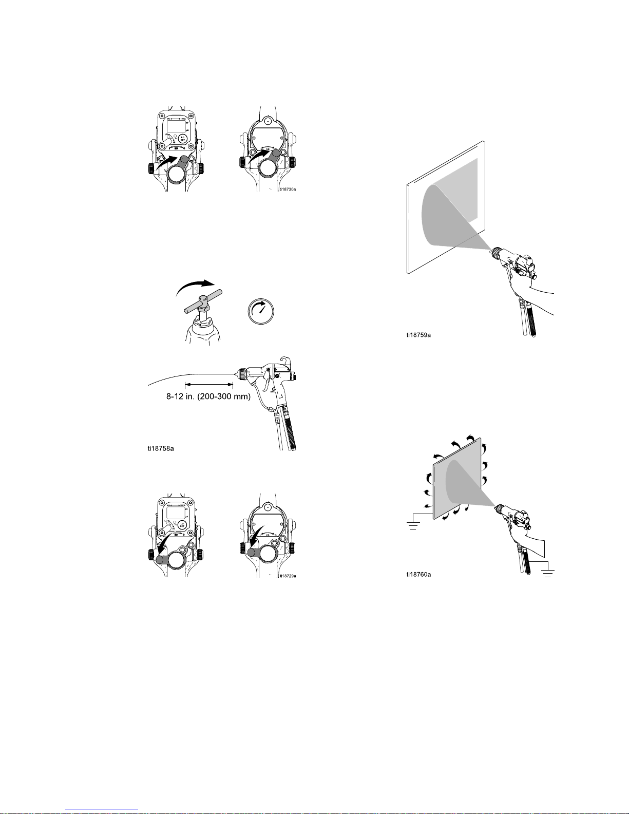
20.Startthepump.Adjusttheuidregulatoruntilthe
streamfromtheguntravels8-12in.(200-300
mm)beforefallingoff.Typically,ifuidpressure
isbelow5psi(.04MPa,0.4bar)orabove30psi
(0.21MPa,2.1bar),achangeofnozzlesizeis
recommended.
21.Turnontheairtothegun.TurnON(I)theES
On-Offswitch(J).
22.Sprayatestpattern.Checktheatomization.If
over-atomizationoccursatminimumpressure,
adjusttherestrictorvalve.Ifatomizationis
inadequate,increaseairpressureordecrease
uidow.
23.Adjustthefanairadjustmentvalve:clockwisefor
anarrowerpattern,counterclockwiseforawider
pattern.
24.Sprayatestpiece.Examinetheedges
forcoverage.Ifwrapispoor,see
Troubleshooting,page33.
20 3A2494D
Page 21
GunSetup
Grounding Grounding
Grounding
Whenoperatingtheelectrostaticgun,any
ungroundedobjectsinthesprayarea(people,
containers,tools,etc.)canbecomeelectrically
charged.Impropergroundingcanresultinstatic
sparking,whichcancauseare,explosion,or
electricshock.Groundallequipment,personnel,
objectbeingsprayed,andconductiveobjects
inorclosetothesprayarea.Resistancemust
notexceed1megohm.Followthegrounding
instructionsbelow.
Thefollowingareminimumgroundingrequirements
forabasicelectrostaticsystem(seeFigs.12–15).
Yoursystemmayincludeotherequipmentorobjects
whichmustbegrounded.Checkyourlocalelectrical
codefordetailedgroundinginstructions.Yoursystem
mustbeconnectedtoatrueearthground.
•
Pump/uid source:
groundthepump/uidsource
byconnectingitsgroundwiretoatrueearth
ground.
•
Electrostatic Air Spray Gun:
groundthegun
byconnectingtheGracoGroundedAirHose
(AH)tothegun,andconnectingtheairhose
groundwiretoatrueearthground.See
CheckGunElectricalGrounding,page25.
•
Object being sprayed:
keeptheworkpiecehangers
cleanandgroundedatalltimes.
•
All electrically conductive objects or devices in the
spray area:
mustbeproperlygrounded.
•
Fluid and waste containers:
groundalluidand
wastecontainersinthesprayarea.Donotusepail
linersunlesstheyareconductiveandgrounded.
Whenushingthespraygun,thecontainerused
tocatchtheexcessuidmustbeelectrically
conductiveandgrounded.
•
Air compressors:
groundtheequipmentaccording
tothemanufacturer'srecommendations.
•
All air and uid lines
mustbeproperlygrounded.
Useonlygroundedhoseswithamaximumof100
feet(30.5m)combinedhoselengthtoensure
groundingcontinuity.
3A2494D
21
Page 22
GunSetup
•
The oor of the spray area:
mustbeelectrically
conductiveandgrounded.Donotcovertheoor
withcardboardoranynon-conductivematerial
whichwouldinterruptgroundingcontinuity.
•
Flammable liquids in the spray area:
mustbekept
inapproved,groundedcontainers.Donotuse
plasticcontainers.Donotstoremorethanthe
quantityneededforoneshift.
•
All persons entering the spray area:
mustwear
shoeshavingconductivesolessuchasleather,
orwearpersonalgroundingstraps.Donot
wearshoeswithnon-conductivesolessuchas
rubberorplastic.Ifglovesarenecessary,wear
theconductiveglovessuppliedwiththegun.If
non-Gracoglovesareworn,cutoffngersorpalm
areaofglovestoensureyourhandcontactsthe
groundedgunhandle.
Key Key
Key
to totoFigs. Figs.
Figs.
12–15 12–15
12–15
Fig.12
Operatorisgroundedthrough
bareskincontactwiththegun
handleandconductiveshoes.A
conductiveglovecanalsobeused.
Fig.13
Objectbeingsprayedisgrounded
throughcontactwiththehanger
andconveyorsystem.
Fig.14
Gunisgroundedthroughthe
conductiveairhose.
Fig.15Fluidsupplylineandsourcemust
begrounded.
22
3A2494D
Page 23
GunSetup
Figure12GroundtheOperator
Figure13GroundtheObjectBeingSprayed
3A2494D 23
Page 24
GunSetup
Figure14GroundtheGun
Figure15GroundtheFluidSupply
24
3A2494D
Page 25

GunSetup
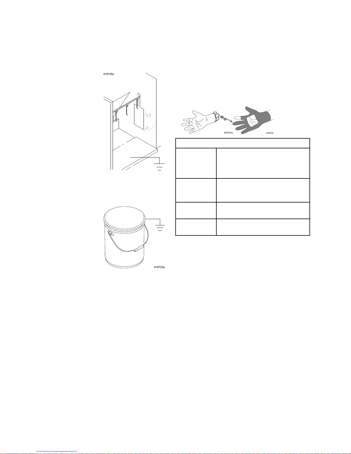
Check Check
Check
Gun Gun
Gun
Electrical Electrical
Electrical
Grounding Grounding
Grounding
MegohmmeterPartNo.241079(AA-seeFig.
16)isnotapprovedforuseinahazardousarea.
Toreducetheriskofsparking,donotusethe
megohmmetertocheckelectricalgrounding
unless:
•Thegunhasbeenremovedfromthehazardous
area;
•Orallsprayingdevicesinthehazardousarea
areturnedoff,ventilationfansinthehazardous
areaareoperating,andtherearenoammable
vaporsinthearea(suchasopensolvent
containersorfumesfromspraying).
Failuretofollowthiswarningcouldcausere,
explosion,andelectricshockandresultinserious
injuryandpropertydamage.
GracoPartNo.241079Megohmmeterisavailable
asanaccessorytocheckthatthegunisproperly
grounded.
1.Haveaqualiedelectricianchecktheelectrical
groundingcontinuityofthespraygunandair
hose.
2.TurnOFF(O)theESOn-Offswitch.
3.Turnofftheairanduidsupplytothegun.Follow
thePressureReliefProcedure,page27.
4.Disconnecttheuidhose.
5.Makesurethegroundedairhose(AH)is
connectedandthehosegroundwireis
connectedtoatrueearthground.
6.Measuretheresistancebetweenthegunhandle
(BB)andatrueearthground(CC).Usean
appliedvoltageof500minimumto1000volts
maximum.Theresistanceshouldnotexceed1
megohm.SeeFig.16.
7.Iftheresistanceisgreaterthan1megohm,check
thetightnessofthegroundconnectionsandbe
suretheairhosegroundwireisconnectedtoa
trueearthground.Iftheresistanceisstilltoo
high,replacetheairhose.
Figure16CheckGunElectricalGrounding
3A2494D 25
Page 26

GunSetup
Check Check
Check
Fluid Fluid
Fluid
Resistivity Resistivity
Resistivity
Toreducetheriskofre,explosion,orelectric
shock,checktheuidresistivityinanon-hazardous
areaonly.ResistanceMeter722886andProbe
722860arenotapprovedforuseinahazardous
area.
Failuretofollowthiswarningcouldcausere,
explosion,orelectricshockandresultinserious
injuryandpropertydamage.
GracoPartNo.722886ResistanceMeterand
722860Probeareavailableasaccessoriestocheck
thattheresistivityoftheuidbeingsprayedmeets
therequirementsofanelectrostaticairspraysystem.
Followtheinstructionsincludedwiththemeterand
probe.Readingsof25megohms-cmandabove
providethebestelectrostaticresults.
Ahighconductivitykitorhighconductivityhosemay
berequiredforreadingslessthan25megohm-cm.
Table Table
Table
4 44. ..Fluid Fluid
Fluid
Resistivity Resistivity
Resistivity
Levels Levels
Levels
Megohms Megohms
Megohms
- --cm cm
cm
1–77–2525–200200–2000
HighConductivity
Kitrecommended
HighConductivity
Kitmaybe
needed
Bestelectrostatic
results
Goodelectrostatic
results
Check Check
Check
Fluid Fluid
Fluid
Viscosity Viscosity
Viscosity
Tocheckuidviscosityyouwillneed:
•aviscositycup
•astopwatch.
1.Completelysubmergetheviscositycupin
theuid.Liftthecupoutquickly,startingthe
stopwatchassoonasthecupiscompletely
removed.
2.Watchthestreamofuidcomingfromthebottom
ofthecup.Assoonasthereisabreakinthe
stream,shutoffthestopwatch.
3.Recordtheuidtype,elapsedtime,andsizeof
theviscositycup.
4.Iftheviscosityistoohighortoolow,contactthe
materialsupplier.Adjustasnecessary.
Flush Flush
Flush
Before Before
Before
Using Using
Using
Equipment Equipment
Equipment
Theequipmentwastestedinuidatthefactory.To
avoidcontaminatingyouruid,ushtheequipment
withacompatiblesolventbeforeusingtheequipment.
Guidelines Guidelines
Guidelines
for for
for
Abrasive Abrasive
Abrasive
Materials Materials
Materials
Whensprayingabrasivematerials,followthese
guidelines:
•OrderPartNo.24N704Electrode(blue)for
abrasivematerials.
•Sizethenozzleproperlytoreduceuidpressure
below30psi(0.21MPa,2.1bar),producingan
8–12in.(200–300mm)uidstream.
•Operatethegunwiththeuidadjustmentknobin
thefullowpositionatalltimes.Useanexternal
uidregulator,nottheuidadjustmentknob,toset
theuidpressure.
•Usetheminimumatomizingandfanairpressures
possibletoachieveagoodpattern.
•Followallproceduresunder
CleantheGunDaily,page29.
•Inspecttheelectrodedailyandreplaceifdamaged.
SeeElectrodeReplacement,page39.
26 3A2494D
Page 27

Operation
Operation Operation
Operation
Pressure Pressure
Pressure
Relief Relief
Relief
Procedure Procedure
Procedure
1.TurnOFF(O)theESOn/Offswitch.
2.Turnofftheairbleedvalvestotheuidsource
andtothegun.
3.Triggerthegunintoagroundedmetalwaste
containertorelievetheuidpressure.
4.Openthepumpdrainvalve,havingawaste
containerreadytocatchthedrainage.Leave
thepumpdrainvalveopenuntilyouareready
tosprayagain.
5.Ifthenozzleorhoseiscompletelycloggedor
pressureisnotfullyrelieved,slowlyloosenthe
hoseendcoupling.Nowclearthenozzleorhose.
Startup Startup
Startup
FollowallstepsunderGunSetupChecklist,page18.
Shutdown Shutdown
Shutdown
1.Flushthegun,seeFlushing,page28.
2.FollowthePressureReliefProcedure,page27.
3.Hangthegunfromitshook,withthenozzle
pointingdown.
3A2494D
27
Page 28

Maintenance
Maintenance Maintenance
Maintenance
Flushing Flushing
Flushing
•Flushbeforechanginguids,beforeuidcandry
intheequipment,attheendoftheday,before
storing,andbeforerepairingequipment.
•Flushatthelowestpressurepossible.Check
connectorsforleaksandtightenasnecessary.
•Flushwithauidthatiscompatiblewiththeuid
beingdispensedandtheequipmentwettedparts.
Toreducetheriskofre,explosion,orelectric
shock,turnOFF(O)theESOn-Offswitchbefore
ushingthegun.
NOTICE NOTICE
NOTICE
Donotusemethylenechlorideasaushingor
cleaningsolventwiththisgunasitwilldamage
nyloncomponents.
1.TurnOFF(O)theESOn-Offswitch.
2.FollowthePressureReliefProcedure,page27.
3.Changetheuidsourcetosolvent,ordisconnect
theuidlineandconnectasolventsupplyline
tothegun.
4.Pointthegunintoagroundedmetalpail.Flush
untilcleansolventowsfromthegun.
5.FollowthePressureReliefProcedure,page27.
6.Shutoffordisconnectthesolventline.
7.Hangthegunfromitshook,withthenozzle
pointingdown.
8.Whenreadytosprayagain,reconnect
theuidsupplyline.Followthe
GunSetupChecklist,page18.
28 3A2494D
Page 29

Maintenance
Clean Clean
Clean
the the
the
Gun Gun
Gun
Daily Daily
Daily
1.TurnOFF(O)theESOn-Offswitch.
2.Flushthegun.SeeFlushing,page28.
3.FollowthePressureReliefProcedure,page27.
4.Cleantheoutsideofthegunwithacompatible
solvent.Useasoftcloth.Pointthegundownto
preventsolventfromenteringthegunpassages.
Donotimmersethegun.
5.Removetheaircap.
6.Cleantheaircap,retainingring,andnozzlewith
asoftbrushandcompatiblesolvent.
7.Ifnecessary,useatoothpickorothersofttoolto
cleantheaircapholes.Donotusemetaltools.
8.Reinstalltheaircap.Tightensecurely.
3A2494D 29
Page 30

Maintenance
Daily Daily
Daily
System System
System
Care Care
Care
1.FollowthePressureReliefProcedure,page27.
2.Cleantheuidandairlters.
3.Checkforuidleaks.Tightenallttings.
4.Cleanworkpiecehangers.Usenon-sparking
tools.
5.Checkthemovementofthetriggerandvalves.
Lubricateifnecessary.
6.CheckGunElectricalGrounding,page25.
7.Hangthegunfromitshook,withthenozzle
pointingdown.
30 3A2494D
Page 31

ElectricalTests
Electrical Electrical
Electrical
Tests Tests
Tests
Usethefollowingprocedurestotestthecondition
ofthepowersupplyandgunbody,andelectrical
continuitybetweencomponents.
UsemegohmmeterPartNo.241079(AA)andan
appliedvoltageof500V.Connecttheleadsas
shown.
MegohmmeterPartNo.241079(AA-seeFig.
17)isnotapprovedforuseinahazardousarea.
Toreducetheriskofsparking,donotusethe
megohmmetertocheckelectricalgrounding
unless:
•Thegunhasbeenremovedfromthehazardous
area;
•Orallsprayingdevicesinthehazardousarea
areturnedoff,ventilationfansinthehazardous
areaareoperating,andtherearenoammable
vaporsinthearea(suchasopensolvent
containersorfumesfromspraying).
Failuretofollowthiswarningcouldcausere,
explosion,andelectricshockandresultinserious
injuryandpropertydamage.
Test Test
Test
Gun Gun
Gun
Resistance Resistance
Resistance
1.Flushanddrytheuidpassage.
2.For For
For
Model Model
Model
L40T14 L40T14
L40T14
and and
and
L40T15 L40T15
L40T15
guns guns
guns
only: only:
only:
Test
thebarrelcontinuitytoverifythatthemetalpin
inthebarrelisproperlygrounded.Measure
resistancebetweenthemetalpin(GP)andthe
airswivel(21).Theresistanceshouldbeless
than100ohms.Iftheresistanceis100ohmsor
more,replacethegunbody.
3.For For
For
all all
all
guns: guns:
guns:
Triggerthegunandmeasure
resistancebetweentheelectrodeneedletip(3)
andtheairswivel(21).Theresistanceshouldbe:
•75–120megohmsfor40kVguns
•104–148megohmsfor60kVguns
•148–193megohmsfor85kVguns
Ifoutsidethisrange,testthegun
untriggered.Ifstilloutsidethisrange,goto
TestPowerSupplyResistance,page32.Ifinrange,
seeElectricalTroubleshooting,page35forother
possiblecausesofpoorperformance.
Figure17TestGunResistance
3A2494D 31
Page 32

ElectricalTests
Test Test
Test
Power Power
Power
Supply Supply
Supply
Resistance Resistance
Resistance
1.Removethepowersupply(11).SeePower
SupplyRemovalandReplacement,page43.
2.Removethealternator(15)
fromthepowersupply.See
AlternatorRemovalandReplacement,page44.
3.Measureresistancefromthepowersupply's
groundstrips(EE)tothespring(11a).The
resistanceshouldbe:
•60–85megohmsfor40kVguns
•86–110megohmsfor60kVguns
•130–160megohmsfor85kVguns
4.Ifoutsidethisrange,replacethe
powersupply.Ifinrange,goto
TestElectrodeResistance,page32.
5.Ifyoustillhaveproblems,referto
ElectricalTroubleshooting,page35for
otherpossiblecausesofpoorperformance,or
contactyourGracodistributor.
6.Besurethespring(11a)isinplacebefore
reinstallingthepowersupply.
Figure18TestPowerSupplyResistance
Test Test
Test
Electrode Electrode
Electrode
Resistance Resistance
Resistance
Removetheelectrode(3).See
ElectrodeReplacement,page39.Measure
theresistancebetweenthecontact(HH)andthe
electrodewire(GG).Theresistanceshouldbe8-30
megohms.Ifoutofrange,replacetheelectrode.
NOTE: NOTE:
NOTE:
Ifthegunresistanceisstilloutofrangeafter
testingthepowersupplyandelectrode:
•Checkthattheconductiveo-ring(4a)ismaking
contactwiththebarrelpin.
•Checkthatthepowersupplyspring(11a)ismaking
contactwiththebarrelpin.
Figure19TestElectrodeResistance
32 3A2494D
Page 33

Troubleshooting
Troubleshooting Troubleshooting
Troubleshooting
Installingandservicingthisequipmentrequires
accesstopartswhichmaycauseanelectricshock
orotherseriousinjuryiftheworkisnotperformed
properly.Donotinstallorrepairthisequipment
unlessyouaretrainedandqualied.
Toreducetheriskofaninjury,followthe
PressureReliefProcedure,page27,whenever
youareinstructedtorelievethepressure.
CheckallpossibleremediesintheTroubleshootingChartbeforedisassemblingthegun.
Spray Spray
Spray
Pattern Pattern
Pattern
Troubleshooting Troubleshooting
Troubleshooting
Somespraypatternproblemsarecausedbytheimproperbalancebetweenairanduid.
Problem Problem
Problem
Cause Cause
Cause
Solution Solution
Solution
Nouid.Rellsupply.
Loose,dirty,damaged
nozzle/seat.
Cleanorreplacenozzle,see
CleantheGunDaily,page29,or
AirCapandNozzleReplacement,
page38.
Flutteringorspittingspray.
Airinuidsupply.Checkuidsource.Rell.
Improperspraypattern.Damagedordirtynozzleoraircap.
Cleanorreplace.SeeAirCapand
NozzleReplacement,page38.
Fluidbuilduponaircapornozzle.
Clean.See
CleantheGunDaily,page29.
Fanairpressuretoohigh.Decrease.
Fluidtoothin.Increaseviscosity.
Fluidpressuretoolow.Increase.
Fanairpressuretoolow.Increase.
Fluidtoothick.Reduceviscosity.
Toomuchuid.Decreaseow.
Didnotapply50%overlap.Overlapstrokes50%. Streaks.
Dirtyordamagedaircap.
Cleanorreplaceaircap.See
CleantheGunDaily,page29,or
AirCapandNozzleReplacement,
page38.
3A2494D 33
Page 34

Troubleshooting
Gun Gun
Gun
Operation Operation
Operation
Troubleshooting Troubleshooting
Troubleshooting
Problem Problem
Problem
Cause Cause
Cause
Solution Solution
Solution
Atomizingairpressuretoohigh.
Closerestrictorvalvepartway,or
decreaseairpressureaslowas
possible;minimum45psi(0.32
MPa,3.2bar)neededatgunfor
fullvoltage.
Excessivesprayfog.
Fluidtoothin,oruidowistoo
low.
Increaseviscosityorincreaseuid
owrate.
Atomizingairpressuretoolow.
Openatomizingairvalvemoreor
increasegunairinletpressure;
uselowestairpressurenecessary.
Poorlymixedorltereduid.Remixorrelteruid.
“OrangePeel”nish.
Fluidtoothick.Reduceviscosity.
Fluidleaksfromtheuidpacking
area.
Wornpackingsorrod.
SeePackingRodRepair,page40.
Airleaksfromthefrontofthegun.
Airvalveisnotseatingproperly.
SeeAirValveRepair,page50.
Wornordamageduidpacking
rodorelectrode.
Replacepackingrod(2e)
orelectrode(3).See
PackingRodRepair,page40or
ElectrodeReplacement,page39.
Wornuidnozzleseat.Replacenozzle(4).See
AirCapandNozzleReplacement,
page38.
Looseuidnozzle.
Tighten.
Fluidleakagefromthefrontofthe
gun.
Damagednozzleo-ring.
SeeAirCapandNozzle
Replacement,page38.
Lowuidsupply.Adduidifnecessary.
Dirtyorcloggeduidnozzle.Clean.See
CleantheGunDaily,page29.
Gundoesnotspray.
Closedordamageduid
adjustmentvalve.
Openvalve,orsee
ESOn-OffandFluidAdjustment
ValveRepair,page49.
Dirtyaircap.
Misalignedaircapanduidnozzle.Cleanuidbuildupoffaircap
anduidnozzleseat.See
CleantheGunDaily,page29.
Poorgrounding.
SeeGrounding,page21.
Excessivepaintwrapbackto
operator.
Incorrectdistancefromguntopart.Shouldbe8–12in.(200–300mm).
34 3A2494D
Page 35

Troubleshooting
Electrical Electrical
Electrical
Troubleshooting Troubleshooting
Troubleshooting
Problem Problem
Problem
Cause Cause
Cause
Solution Solution
Solution
ESOn/OffswitchisOFF(O).TurnON(I).
Gunairpressuretoolow(ES
indicatorisamber).
Checkairpressuretogun;
minimum45psi(0.32MPa,3.2
bar)neededatgunforfullvoltage.
Atomizingairpressuretoohigh.Decrease.
Incorrectdistancefromguntopart.Shouldbe8-12in.(200-300mm).
Poorlygroundedparts.Resistancemustbe1megohmor
less.Cleanworkpiecehangers.
Faultygunresistance.
See
TestGunResistance,page31.
Lowuidresistivity.See
CheckFluidResistivity,page26.
Fluidleaksfromthepacking(2c)
andcausesashort.
SeePackingRodRepair,page40.
Poorwrap.
Faultyalternator.
SeeAlternatorRemovaland
Replacement,page44.
ESOn/OffswitchisOFF(O).TurnON(I). ESorHzindicatorisnotlit.
Nopower.
Checkpowersupply,alternator,
andalternatorribboncable.See
PowerSupplyRemovaland
Replacement,page43and
AlternatorRemovaland
Replacement,page44.
Operatornotgroundedorisnear
ungroundedobject.
SeeGrounding,page21. Operatorgetsmildshock.
Gunnotgrounded.SeeCheckGunElectrical
Grounding,page25,and
TestGunResistance,page31.
Operatorgetsshockfrom
workpiece.
Workpiecenotgrounded.Resistancemustbe1megohmor
less.Cleanworkpiecehangers.
3A2494D 35
Page 36

Troubleshooting
Problem Problem
Problem
Cause Cause
Cause
Solution Solution
Solution
Gunistooclosetothepartbeing
sprayed.
Gunshouldbe8–12in.(200–300
mm)fromthepart.
Checkuidresistivity.See
CheckFluidResistivity,page26.
Voltage/currentdisplaystaysred
(smartgunsonly).
Dirtygun.
SeeCleantheGunDaily,page29.
ESorHZindicatorisamber.
Alternatorspeedistoolow.Increaseairpressureuntil
indicatorisgreen.Toavoid
over-atomization,usethe
atomizingairrestrictorvalveto
reducetheatomizingairtotheair
cap.
ESorHzindicatorisred.
Alternatorspeedistoohigh.Decreaseairpressureuntil
indicatorisgreen.
ErrordisplayappearsandHz
indicatorisred(Smartgunsonly).
Smartmodulehaslost
communicationwiththepower
supply.
CheckforgoodconnectionsbetweentheSmartModuleandthe
powersupply.SeeSmartModule
Replacement,page51and
PowerSupplyRemovaland
Replacement,page43.
36 3A2494D
Page 37

Repair
Repair Repair
Repair
Prepare Prepare
Prepare
the the
the
Gun Gun
Gun
for for
for
Service Service
Service
Installingandrepairingthisequipmentrequires
accesstopartsthatmaycauseelectricshockor
otherseriousinjuryiftheworkisnotperformed
properly.Donotinstallorservicethisequipment
unlessyouaretrainedandqualied.
•Checkallpossibleremedies
inTroubleshooting,page33beforedisassembling
thegun.
•Useavisewithpaddedjawstopreventdamage
toplasticparts.
•Lubricatesomepackingrodparts(2)andcertain
uidttingswithdielectricgrease(44),asspecied
inthetext.
•Lightlylubricateo-ringsandsealswithnon-silicone
grease.OrderPartNo.111265Lubricant.Donot
over-lubricate.
•OnlyusegenuineGracoparts.Donotmixoruse
partsfromotherProGunmodels.
•AirSealRepairKit24N789isavailable.The
kitmustbepurchasedseparately.Kitpartsare
markedwithanasterisk,forexample(6a*).
•FluidSealRepairKit24N790isavailable.The
kitmustbepurchasedseparately.Kitpartsare
markedwithasymbol,forexample(2a‡).
1.Flushthegun.SeeFlushing,page28.
2.Relievethepressure.See
PressureReliefProcedure,page27.
3.Disconnectthegunairanduidlines.
4.Removethegunfromtheworksite.Repairarea
mustbeclean.
3A2494D 37
Page 38

Repair
Air Air
Air
Cap Cap
Cap
and and
and
Nozzle Nozzle
Nozzle
Replacement Replacement
Replacement
NOTICE NOTICE
NOTICE
Triggerthegunwhileremovingthenozzletohelp
drainthegunandpreventanypaintorsolventleft
inthegunfromenteringtheairpassages.
1.SeePreparetheGunforService,page37.
2.Removetheretainingring(6)andaircap(5).
3.Triggerthegunwhileremovingtheuidnozzle
(4)assemblywiththemulti-tool(41).
Thenozzlecontactring(4a)isaconductive
contactring,notasealingo-ring.Toreduce
theriskofsparkingorelectricshock,donot
removethenozzlecontactring(4a)exceptto
replaceitandneveroperatethegunwithout
thecontactringinplace.Donotreplacethe
contactringwithanythingbutagenuineGraco
part.
NOTICE NOTICE
NOTICE
Usenon-siliconegrease,PartNo.111265,on
thesmallo-ring(4b).Donotover-lubricate.Do
notlubricatetheconductivecontactring(4a).
4.Makesuretheconductivecontactring(4a)and
thesmallo-ring(4b)areinplaceonthenozzle
(4).Lightlylubricatethesmallo-ring(4b).
NOTE: NOTE:
NOTE:
Theconductivecontactring(4a)may
showsomewearatthepointwhereitmakes
contactwiththebarrelpin.Thisisnormaland
doesnotrequirereplacement.
5.Makesuretheelectrodeneedle(3)isnger-tight.
6.Triggerthegunwhileinstallingtheuidnozzle
(4)withthemulti-tool(41).Tightenuntiltheuid
nozzleseatsinthegunbarrel(1/8to1/4turn
pasthand-tight).
7.Installtheaircap(5)andretainingring(6).Make
suretheu-cup(6a*)isinplacewiththelipsfacing
forward.
8.SeeTestGunResistance,page31.
Figure20AirCapandNozzleReplacement
38 3A2494D
Page 39

Repair
Electrode Electrode
Electrode
Replacement Replacement
Replacement
1.SeePreparetheGunforService,page37.
2.Removetheaircapandnozzle.See
AirCapandNozzleReplacement,page38.
3.Unscrewtheelectrode(3)withthemulti-tool(41).
NOTICE NOTICE
NOTICE
Toavoiddamagingtheplasticthreads,bevery
carefulwheninstallingtheelectrode.
4.Applylow-strength(purple)Loctite®orequivalent
threadsealanttotheelectrodeandpackingrod
threads.Installtheelectrodenger-tight.Donot
overtighten.
5.Installtheuidnozzleandaircap.See
AirCapandNozzleReplacement,page38.
6.SeeTestGunResistance,page31.
Figure21ElectrodeReplacement
3A2494D 39
Page 40

Repair
Fluid Fluid
Fluid
Packing Packing
Packing
Rod Rod
Rod
Removal Removal
Removal
1.SeePreparetheGunforService,page37.
2.Removetheaircapanduidnozzle.See
AirCapandNozzleReplacement,page38.
3.Removetheelectrode.See
ElectrodeReplacement,page39.
4.Loosenthetriggerscrews(13)andremovethe
trigger(12).
5.Removethepackingrod(2),usingthemulti-tool
(41).Removethespring(17).
6.Checkallpartsforwearordamageandreplace
ifnecessary.
Figure22FluidPackingRodRemoval
Packing Packing
Packing
Rod Rod
Rod
Repair Repair
Repair
NOTE: NOTE:
NOTE:
Youmayreplacethepackingrodasindividual
partsorasanassembly.
Adjust Adjust
Adjust
the the
the
Air Air
Air
Flow Flow
Flow
Lead Lead
Lead
and and
and
Lag Lag
Lag
NOTE: NOTE:
NOTE:
Thegunbeginsemittingairbeforetheuid
isdischargedandtheuidstopsbeforetheairow
stops.Thepackingrodassemblyispre-adjustedat
thefactoryforproperairleadandlag.Adjustonly
ifnecessary,asfollows.
1.Removethespring(17)fromthenut(2k).
2.Useahexwrenchtoholdtheendofthepacking
rod.Turnbothadjustmentnuts(2j,2k)outto
increasethelead/lagtimefortheairow.The
recommendedadjustmentisonehalfturnand
notmorethanonefullturn.
3.Tightenthenutstogethertoxtheminthenew
position.
40 3A2494D
Page 41

Repair
Assemble Assemble
Assemble
the the
the
Packing Packing
Packing
Rod Rod
Rod
NOTE: NOTE:
NOTE:
Beforeinstallingtheuidpackingrodintothe
gunbarrel,makesuretheinternalsurfacesofthe
barrelareclean.Removeanyresiduewithasoft
brushorcloth.Checktheinsideofthebarrelfor
marksfromhighvoltagearcing.Ifmarksarepresent,
replacethebarrel.
1.Placethepackingnut(2f)andseal(2b‡)onthe
uidrod(2e).Flatsonthepackingnutmustface
thebackoftheuidrod.Thesealo-ringmust
faceawayfromthepackingnut.
2.Filltheinnercavityofthespacer(2h‡)with
dielectricgrease(44).Placethespaceronthe
uidrod(2e)inthedirectionshown.Generously
applydielectricgreasetotheoutsideofthe
spacer.
3.Placetheuidpacking(2c‡)onthepackingrod
(2e)withitslipsfacingthefrontoftherod.Install
theneedlepacking(2d‡)withthemaleend
towardtheuidpacking,theninstallthehousing
(2g).
4.Lightlytightenthepackingnut(2f).Thepacking
nutisproperlytightenedwhenthereis3lb(13.3
N)ofdragforcewhenslidingthepackinghousing
(2g)assemblyalongtherod.Tightenorloosen
thepackingnutasneeded.
5.Installtheo-ring(2a‡)ontheoutsideofhousing
(2g).Lubricatetheo-ringwithnon-silicone
grease,PartNo.111265.Donotover-lubricate.
6.Installthespring(17)againstthenut(2j)as
shown.
7.Installthepackingrodassembly(2)intothe
gunbarrel.Usingthemulti-tool(41),tightenthe
assemblyuntiljustsnug.
8.Installtheelectrode.See
ElectrodeReplacement,page39.
9.Installthenozzleandaircap.See
AirCapandNozzleReplacement,page38.
10.Installthetrigger(12)andscrews(13).
11.SeeTestGunResistance,page31.
Figure23PackingRod
3A2494D
41
Page 42

Repair
Barrel Barrel
Barrel
Removal Removal
Removal
1.SeePreparetheGunforService,page37.
2.Carefullyloosenthenut(N)fromthebracketuid
tting(20).Pullthetube(T)outofthetting.
Makesurebothferrules(7,8)andthenutstay
withthetube.
3.Loosenthetwoscrews(27).
NOTICE NOTICE
NOTICE
Toavoiddamagingthepowersupply(11),pull
thegunbarrel(1)straightawayfromthegun
handle(16).Ifnecessary,gentlymovethegun
barrelfromsidetosidetofreeitfromthegun
handle.
4.Holdthegunhandle(16)withonehandandpull
thebarrel(1)straightoffthehandle.
NOTE: NOTE:
NOTE:
Ifthepowersupplyremainsinthebarrel,
removethealternator/powersupplyassemblyfrom
thebarrel.
Figure24BarrelRemoval
Barrel Barrel
Barrel
Installation Installation
Installation
1.Besurethegasket(28*)andgroundingspring
(18)areinplace.Makesurethegasketair
holesarealignedproperly.Replacethegasketif
damaged.
2.Makesurethespring(11a)isinplaceonthetipof
thepowersupply(11).Liberally Liberally
Liberally
applydielectric
grease(44)tothetipofthepowersupply.Place
thebarrel(1)overthepowersupplyandontothe
gunhandle(16).
3.Tightenthetwoscrews(27)oppositelyand
evenly(aboutahalfturnpastsnug).Donot
over-tightenthescrews(27).
4.Assembletheuidtube(T)intothebrackettting
(20).Ensurethattheferrules(7,8)areinplace.
Tightenthenut(N)securelyontothetting.
Makesurethetopttingremainstight.
5.SeeTestGunResistance,page31.
Figure25BarrelInstallation
42
3A2494D
Page 43
Repair
Power Power
Power
Supply Supply
Supply
Removal Removal
Removal
and and
and
Replacement Replacement
Replacement
•Inspectthegunhandlepowersupplycavityfordirt
ormoisture.Cleanwithaclean,dryrag.
•Donotexposegasket(28)tosolvents.
1.SeePreparetheGunforService,page37.
2.SeeBarrelRemoval,page42.
NOTICE NOTICE
NOTICE
Becarefulwhenhandlingthepowersupply
(11)toavoiddamagingit.
3.Graspthepowersupply(11)withyourhand.
Withagentlesidetosidemotion,freethepower
supply/alternatorassemblyfromthegunhandle
(16),thencarefullypullitstraightout.
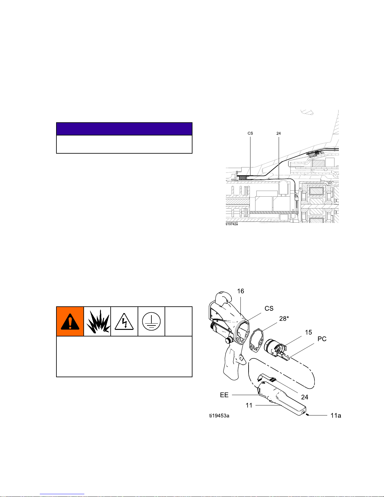
On Smart
Models only,
disconnecttheexiblecircuit(24)
fromthesocketatthetopofthehandle.
4.Inspectthepowersupplyandalternatorfor
damage.
5.Toseparatethepowersupply(11)fromthe
alternator(15),disconnectthe3-wireribbon
connector(PC)fromthepowersupply.
On Smart
Models only,
disconnectthe6–pinexiblecircuit
(24)fromthepowersupply.Slidethealternator
upandoffthepowersupply.
6.SeeTestPowerSupplyResistance,page32.
Replacethepowersupplyifnecessary.
Torepairthealternator,see
AlternatorRemovalandReplacement,page44.
Topreventdamagetothecableandpossible
interruptionofthegroundcontinuity,bendthe
alternator’s3–wireribboncable(PC)upward
andback,sothebendfacesthepowersupply
andtheconnectorisatthetop.
7.
Smart models only:
connectthe6–pinexible
circuit(24)tothepowersupply.
8.Connectthe3-wireribbonconnector(PC)tothe
powersupply.Tucktheribbonforward,under
thepowersupply.Slidethealternator(15)down
ontothepowersupply(11).
9.Insertthepowersupply/alternatorassemblyin
thegunhandle(16).Makesurethegroundstrips
(EE)makecontactwiththehandle.OnSmart
models,aligntheconnectorofthe6–pinexible
circuit(24)withthesocket(CS)atthetopofthe
handle.Pushtheconnectorsecurelyintothe
socketasyouslidethepowersupply/alternator
assemblyintothehandle.
Figure26ConnectFlexibleCircuit
10.Makesurethegasket(28*),groundspring(18),
andpowersupplyspring(11a)areinplace.
Assemblethebarrel(1)tothehandle(16).See
BarrelInstallation,page42.
11.SeeTestGunResistance,page31.
Figure27PowerSupply
3A2494D 43
Page 44

Repair
Alternator Alternator
Alternator
Removal Removal
Removal
and and
and
Replacement Replacement
Replacement
NOTE: NOTE:
NOTE:
Replacealternatorbearingsafter2000hours
ofoperation.OrderPartNo.24N706BearingKit.
Partsincludedinthekitaremarkedwithasymbol(♦).
1.SeePreparetheGunforService,page37.
2.Removethepowersupply/alternatorassembly
anddisconnectthealternator.SeePowerSupply
RemovalandReplacement,page43.
3.Measureresistancebetweenthetwoouter
terminalsofthe3-wireconnector(PC);itshould
be2.0–6.0ohms.Ifoutsidethisrange,replace
thealternatorcoil(15a).
4.Usingaatbladescrewdriver,prytheclip(15h)
offthehousing(15d).Removethecap(15f),
usingathinbladeorscrewdriver.
5.Ifnecessary,rotatethefan(15e)soitsblades
clearthefourbearingtabs(T)ofthehousing
(15d).
Figure28FanOrientation
6.Pushthefanandcoilassembly(15a)outthe
frontofthehousing(15d).
Figure29AlternatorCross-Section
NOTICE NOTICE
NOTICE
Donotscratchordamagethemagnet(M)or
shaft(S).Donotpinchordamagethe3–wire
connector(PC)whendisassemblingand
reassemblingthebearings.
7.Holdthecoilassembly(15a)onaworkbench
withthefanendfacingup.Usingawideblade
screwdriver,prythefan(15e)offtheshaft(S).
8.Removethetopbearing(15b2).
9.Removethebottombearing(15b1).
10.Installthenewbottombearing(15b1♦)onthe
longendoftheshaft(S).Theattersideofthe
bearingmustfaceawayfromthemagnet(M).
Installinthecoil(15a)sothebearingbladesare
ushwiththesurfaceofthecoil.
11.Pressthenewtopbearing(15b2♦)ontotheshort
endoftheshaftsothebearingbladesareush
withthesurfaceofthecoil(15a).Theatterside
ofthebearingmustfaceawayfromthecoil.
44
3A2494D
Page 45

Repair
12.Holdthecoilassembly(15a)onaworkbench
withthefanendfacingup.Pressthefan(15e♦)
ontothelongendoftheshaft(S).Thefanblades
mustbeorientedasshown.
13.Carefullypressthecoilassembly(15a)into
thefrontofthehousing(15d♦).The3–wire
connector(PC)mustbepositionedbelowthe
widernotch(W)ofthehousingtabs,asshownin
Fig.45.Besurethecoilalignmentpins(P)are
positionedasshowninFig.44.
14.Rotatethefan(15e)soitsbladesclearthefour
bearingtabs(T)atthebackofthehousing.
Ensurethatthebladesofthebottombearing
(15b1♦)alignwiththetabs.
15.Seatthecoilfullyintothehousing(15d♦).Secure
withtheclip(15h♦),ensuringthatitstabsengage
theslotsinthehousing.
16.Ensurethattheo-ring(15g)isinplace.Install
thecap(15f).
17.Installthealternatoronthepowersupply,and
installbothpartsinthehandle.SeePower
SupplyRemovalandReplacement,page43.
Figure30Alternator
3A2494D 45
Page 46

Repair
Fluid Fluid
Fluid
Tube Tube
Tube
Removal Removal
Removal
and and
and
Replacement Replacement
Replacement
1.Removethenut(22)fromthebracket(20).
2.Loosenthetting(9)toremovetheuidtube
(14)fromthebarrel(1).
3.Applydielectricgrease(44)tothethreadsofthe
tting(9)andtheo-ring(10).Ensuretheferrules
(7,8)areinplace.
NOTE: NOTE:
NOTE:
On40kVguns,theo–ring(10★)isnot
used,andferrules(7★)and(8★)arepartofthe
toptting(9).
NOTE: NOTE:
NOTE:
On60and85kVkVguns,checkthatthe
sleeve(SL)isinplacenearthetopoftheuid
tube.
4.Slidethetting(9)ontotheuidtube(14)and
threadthettingintothebarrel(1).Torqueto
25–35in-lb(2.8–3.9N•m).
5.Withtheferrules(7,8)seatedtothebracket(20),
screwthenut(22)securelyontothebracket.
Makesurethetopttingremainstight.
Figure31FluidTube
46 3A2494D
Page 47

Repair
Fan Fan
Fan
Air Air
Air
Adjustment Adjustment
Adjustment
Valve Valve
Valve
Repair Repair
Repair
1.SeePreparetheGunforService,page37.
2.Placeawrenchontheatsofthevalvehousing
(30a)andunscrewthevalvefromthehandle
(16).
NOTE: NOTE:
NOTE:
Youmayreplacethevalveasan
assembly(gotostep9)orreplaceonlytheo-ring
(steps3–9).
3.Removetheretainingring(30d).
4.Turnthevalveshaft(30b)counterclockwiseuntil
itcomesfreefromthevalvehousing(30a).
5.Inspecttheo-ring(30c).Removeifdamaged.
6.Cleanallpartsandinspectforwearordamage.
NOTE: NOTE:
NOTE:
Usenon-siliconegrease,PartNo.
111265.Donotover-lubricate.
7.Whenreassemblingthefanairvalve(30),lightly
lubricatethevalvethreadsandscrewtheshaft
(30b)fullyintothehousing(30a)untilbottomed.
Installtheo-ring(30c*),lubricate,andunscrew
thevalvestemuntiltheo-ringentersthehousing.
8.Reassembletheretainingring(30d).Unscrew
thevalvestemfromthehousinguntilitisstopped
bytheretainingring.
9.Screwthevalveassembly(30)intothegun
handle(16),usingawrenchontheatsofthe
housing.Torqueto15in-lb(1.7N•m).
Figure32FanAirAdjustmentValve
3A2494D
47
Page 48

Repair
Atomizing Atomizing
Atomizing
Air Air
Air
Restrictor Restrictor
Restrictor
Valve Valve
Valve
Repair Repair
Repair
1.SeePreparetheGunforService,page37.
2.Placeawrenchontheatsofthevalvehousing
(29a)andunscrewthevalvefromthehandle
(16).
NOTE: NOTE:
NOTE:
Youmayreplacethevalveasan
assembly(gotostep9)orreplaceonlytheo-ring
(steps3–9).
3.Unscrewthevalvestem(29e).Removethe
retainingring(29d).
4.Turnthevalvebody(29b)counterclockwiseuntil
itcomesfreefromthevalvehousing(29a).
5.Inspecttheo-ring(29c).Removeifdamaged.
6.Cleanallpartsandinspectforwearordamage.
NOTE: NOTE:
NOTE:
Usenon-siliconegrease,PartNo.
111265.Donotover-lubricate.
7.Whenreassemblingtheatomizingairrestrictor
valve(29),lightlylubricatetheo-ring(29c)and
pushthevalvebody(29b)fullyintothehousing
(29a)untilbottomed.
8.Reassembletheretainingring(29d).Threadthe
valvestem(29e)halfwayintothevalvebody
(29b).
9.Aligntheslot(S)inthevalvestemwiththerib(R)
inthegunhandle.Screwthevalveassembly(29)
intothegunhandle(16),usingawrenchonthe
atsofthehousing.Torqueto15in-lb(1.7N•m).
NOTE: NOTE:
NOTE:
Iftheatomizingairrestrictorvalveisnot
desired,installthesuppliedplug(42).
Figure33AtomizingAirRestrictorValve
Figure34AlignValveStem
48 3A2494D
Page 49

Repair
ES ES
ES
On On
On
- --Off Off
Off
and and
and
Fluid Fluid
Fluid
Adjustment Adjustment
Adjustment
Valve Valve
Valve
Repair Repair
Repair
1.SeePreparetheGunforService,page37.
2.Loosenthecaptivescrew(26p).Removethe
valve(26)fromthehandle.
3.Lubricatetheo-rings(26b*and26m*)with
non-siliconegrease,PartNo.111265.Donot
over-lubricate.
NOTE: NOTE:
NOTE:
Donotover-lubricateparts.Excessive
lubricantontheo-ringscanbepushedintothe
gunairpassageandblemishthenishonthe
workpiece.
4.Cleanandinspectpartsfordamage.Replace
ifnecessary.
NOTE: NOTE:
NOTE:
Theprotrusionontheretainerplate(26h)
mustpointupward.
5.Reinstallthevalve.Torquethescrew(27)to
15-25in-lb(1.7-2.8N•m).
Figure35ESOn-OffandFluidAdjustmentValve
3A2494D 49
Page 50

Repair
Air Air
Air
Valve Valve
Valve
Repair Repair
Repair
1.SeePreparetheGunforService,page37.
2.SeeBarrelRemoval,page42.
3.Removethescrews(13)andtrigger(12).
4.RemovetheESOn-OffValve.SeeESOn-Off
andFluidAdjustmentValveRepair,page49.
5.Removethespring(34).
6.Pushonthefrontoftheairvalveshafttoforceit
outthebackofthehandle.Inspecttherubber
seal(23a*)andreplaceifdamaged.
7.Inspecttheu-cup(35).Donotremovetheu-cup
unlessdamaged.Ifremoved,installthenewone
withitslipsfacingintothegunhandle(16).Place
theu-cupontheshaftoftheairvalvetohelpseat
itinthegunhandle.
Figure36InstallU-Cup
8.Installtheairvalve(23)andspring(34)intothe
gunhandle(16).
9.InstalltheESOn-OffValve.SeeESOn-Offand
FluidAdjustmentValveRepair,page49.
10.Installthetrigger(12)andscrews(13).
11.SeeBarrelInstallation,page42.
Figure37AirValve
50 3A2494D
Page 51

Repair
Smart Smart
Smart
Module Module
Module
Replacement Replacement
Replacement
IftheErrordisplayappears,theSmartModulehas
lostcommunicationwiththepowersupply.Checkfor
goodconnectionsbetweentheSmartModuleand
thepowersupply.
Ifthemodule’sLEDsarenotlighting,replacethe
module.
1.SeePreparetheGunforService,page37.
2.Removethepivotscrew(31e),o-ring(31f),and
ESHI/LOswitch(31c)atthebottomleftcornerof
theSmartModulecartridge(31a).
3.Removetheremainingthreescrews(31d)from
thecartridge.
4.PulltheSmartModuleoutthebackofthegun.
Disconnecttheribboncable(RC)fromthe
connector(GC)inthegunhandle.
5.Removethegasket(31b).
6.Installanewgasket(31b)onthenewcartridge
(31a).Makesurethenotchedcornersofthe
gasketareatthetop.
7.Alignthemodule’sribboncable(RC)with
thegun’scable(GC)andslidethemsecurely
together,asshown.Tucktheconnectedcables
intotherecessofthegunhandle.Installthe
moduleushtothebackofthegunhandle.
8.Installthepivotscrew(31e),o-ring(31f),and
ESHI/LOswitchinthebottomleftcornerofthe
cartridge(31a).
9.Installthethreeremainingscrews(31d).Torque
to7–9in-lb(0.8–1.0N•m).
Figure38SmartModule
Figure39AlignRibbonCables
3A2494D 51
Page 52

Repair
Air Air
Air
Swivel Swivel
Swivel
and and
and
Exhaust Exhaust
Exhaust
Valve Valve
Valve
Replacement Replacement
Replacement
1.SeePreparetheGunforService,page37.
2.Toreplacetheairexhaustvalve:
a.Removetheclamp(43)andtheexhausttube
(36).
b.Unscrewtheswivel(21)fromthegunhandle
(16).Theswivelisaleft-handthread.
Removethebracket(20).
c.Pulltheexhaustvalve(19)fromthehandle
(16).Inspecttheo-ring(19a)andreplaceif
necessary.
d.Installtheo-ring(19a*)ontheexhaustvalve
(19).Lubricatetheo-ringwithalightcoating
ofnon-siliconegrease.
e.Installtheexhaustvalve(19)inthehandle
(16).
f.Applythreadsealanttothetopthreadsofthe
swivel(21).Positionthebracket(20)and
screwtheswivelintothegunhandle(16).
Torqueto75–85in-lb(8.4–9.6N•m).
g.Installthetube(36)andclamp(43).
3.Toreplacetheairinletswivel:
a.Unscrewtheswivel(21)fromthegunhandle
(16).Theswivelisaleft-handthread.
b.Applythreadsealanttothetopthreadsofthe
swivel.Screwtheswivelintothegunhandle.
Torqueto75–85in-lb(8.4–9.6N•m).
Figure40AirInletFittingandAirExhaustValve
52 3A2494D
Page 53

Parts
Parts Parts
Parts
Standard Standard
Standard
Air Air
Air
Spray Spray
Spray
Gun Gun
Gun
Assembly Assembly
Assembly
Part Part
Part
No. No.
No.
L40T10 L40T10
L40T10
40 40
40
kV kV
kV
Electrostatic Electrostatic
Electrostatic
Air Air
Air
Spray Spray
Spray
Gun, Gun,
Gun,
Series Series
Series
A A
A
Part Part
Part
No. No.
No.
L40T14 L40T14
L40T14
40 40
40
kV kV
kV
High High
High
Efciency Efciency
Efciency
Electrostatic Electrostatic
Electrostatic
Air Air
Air
Spray Spray
Spray
Gun, Gun,
Gun,
Series Series
Series
A A
A
Part Part
Part
No. No.
No.
L60T10 L60T10
L60T10
60 60
60
kV kV
kV
Electrostatic Electrostatic
Electrostatic
Air Air
Air
Spray Spray
Spray
Gun, Gun,
Gun,
Series Series
Series
A A
A
Part Part
Part
No. No.
No.
L60T11 L60T11
L60T11
60 60
60
kV kV
kV
Electrostatic Electrostatic
Electrostatic
Round Round
Round
Spray Spray
Spray
Gun, Gun,
Gun,
Series Series
Series
A A
A
Part Part
Part
No. No.
No.
L60T12 L60T12
L60T12
60 60
60
kV kV
kV
Electrostatic Electrostatic
Electrostatic
Air Air
Air
Spray Spray
Spray
Gun, Gun,
Gun,
Series Series
Series
A, A,
A,
with with
with
1.2 1.2
1.2
mm mm
mm
Nozzle Nozzle
Nozzle
Part Part
Part
No. No.
No.
L85T10 L85T10
L85T10
85 85
85
kV kV
kV
Electrostatic Electrostatic
Electrostatic
Air Air
Air
Spray Spray
Spray
Gun, Gun,
Gun,
Series Series
Series
A A
A
3A2494D 53
Page 54

Parts
Part Part
Part
No. No.
No.
L40T10 L40T10
L40T10
40 40
40
kV kV
kV
Electrostatic Electrostatic
Electrostatic
Air Air
Air
Spray Spray
Spray
Gun, Gun,
Gun,
Series Series
Series
A A
A
Part Part
Part
No. No.
No.
L40T14 L40T14
L40T14
40 40
40
kV kV
kV
High High
High
Efciency Efciency
Efciency
Electrostatic Electrostatic
Electrostatic
Air Air
Air
Spray Spray
Spray
Gun, Gun,
Gun,
Series Series
Series
A A
A
Part Part
Part
No. No.
No.
L60T10 L60T10
L60T10
60 60
60
kV kV
kV
Electrostatic Electrostatic
Electrostatic
Air Air
Air
Spray Spray
Spray
Gun, Gun,
Gun,
Series Series
Series
A A
A
Part Part
Part
No. No.
No.
L60T11 L60T11
L60T11
60 60
60
kV kV
kV
Electrostatic Electrostatic
Electrostatic
Round Round
Round
Spray Spray
Spray
Gun, Gun,
Gun,
Series Series
Series
A; A;
A;
see see
see
Round Round
Round
Spray Spray
Spray
Assembly Assembly
Assembly
, ,,page page
page
55 55
55
Part Part
Part
No. No.
No.
L60T12 L60T12
L60T12
60 60
60
kV kV
kV
Electrostatic Electrostatic
Electrostatic
Air Air
Air
Spray Spray
Spray
Gun, Gun,
Gun,
Series Series
Series
A, A,
A,
with with
with
1.2 1.2
1.2
mm mm
mm
Nozzle Nozzle
Nozzle
Part Part
Part
No. No.
No.
L85T10 L85T10
L85T10
85 85
85
kV kV
kV
Electrostatic Electrostatic
Electrostatic
Air Air
Air
Spray Spray
Spray
Gun, Gun,
Gun,
Series Series
Series
A A
A
Ref. Ref.
Ref.
No. No.
No.
Part Part
Part
No. No.
No.
Description Description
Description
Qty Qty
Qty
24N665
BODY,gun;40kVgun
1
24N666
BODY,gun;60kVgun
1
24N667
BODY,gun;85kVgun
1
1
24N668
BODY,gun;40kVhigh
efciencygun
1
2
SeePackingRodAssembly,page62
1
324N651NEEDLE,electrode1
24N616
NOZZLE,1.5mm;includes4a
and4b
1
24N615
NOZZLE,1.2mm;includes4a
and4b
1
4
24N729
NOZZLE,roundspray;
includes4aand4b;see
RoundSprayAssembly,page55
1
4a24N645
O-RING,conductive
1
4b111507
O-RING;uoroelastomer
1
24N477
AIRCAP
1
5
24N731
AIRCAP,roundspray;see
RoundSprayAssembly,page55
1
624N644
RING,retainer;includes6a
1
6a*
198307
PACKING,u-cup;UHMWPE
1
111286
FERRULE,front;40kVgun
1 7‡★
111286
FERRULE,front;60and85kV
guns
2
111285FERRULE,back;40kVgun1 8‡★
111285FERRULE,back;60and85kV
guns
2
24N656
FITTING,uid;40kVgun
1
24N657
FITTING,uid;60kVgun
1
9
24N658
FITTING,uid;85kVgun
1
10★102982
PACKING,o-ring;60and85kV
gunsonly
1
24N659
POWERSUPPLY,40kVgun
1
24N660
POWERSUPPLY,60kVgun
1
11
24N661
POWERSUPPLY,85kVgun
1
11a24N979
SPRING
1
1224N663
TRIGGER;includesitem13
1
Ref. Ref.
Ref.
No. No.
No.
Part Part
Part
No. No.
No.
Description Description
Description
Qty Qty
Qty
1324A445
SCREW,trigger;packageof2
1
24N695
TUBE,uid;40kVgun
1
24N696
TUBE,uid,withsleeve;60kV
gun
1
14
24N697
TUBE,uid,withsleeve;85kV
gun
1
1524N664
See
AlternatorAssembly,page63
1
24N751HANDLE;40kVgun1
24N752HANDLE;60kVgun1
16
24N753HANDLE;85kVgun1
17185111
SPRING,compression
1
18197624
SPRING,compression
1
19249323VALVE,exhaust1
19a*
112085
O-RING
1
2024N741
BRACKET
1
2124N626
SWIVEL,airinlet;M12x1/4
npsm(m);left-handthread
1
2224N698NUT1
2324N633VALVE,air1
23a*
276733
SEAL,airvalve
1
2624N630
SeeESOn-OffandFluid
AdjustmentValve,page64
1
2724N740
SCREW,hexsocket;sst;
packageof2
1
28*
24N699
GASKET,barrel
1
24T304
SeeAtomizingAirRestrictor
ValveAssembly,page65
1 29
24N733Forroundspraygunonly;see
AtomizingAirRestrictorValve
Assembly,page65
1
24N634
SeeFanAirAdjustmentValve
Assembly,page65
1 30
24N732Forroundspraygunonly;
seeFanAirAdjustmentValve
Assembly,page65
1
34185116
SPRING,compression
1
35*
188749
PACKING,u-cup
1
54 3A2494D
Page 55

Parts
Ref. Ref.
Ref.
No. No.
No.
Part Part
Part
No. No.
No.
Description Description
Description
Qty Qty
Qty
36185103
TUBE,exhaust;1/4in.(6mm)
ID(shippedloose)
1
40107460
TOOL,wrench,ballend;4mm
(shippedloose)
1
41276741
MULTI-TOOL(shippedloose)
1
4224N786
PLUG,restrictor(shippedloose;
foruseinsteadofitem29)
1
43110231
CLAMP,exhausttube(shipped
loose)
1
44116553
GREASE,dielectric;1oz(30
ml)tube(notshown)
1
45117824
GLOVE,conductive,medium;
packageof12;alsoavailable
insmall(117823)andlarge
(117825)
1
Ref. Ref.
Ref.
No. No.
No.
Part Part
Part
No. No.
No.
Description Description
Description
Qty Qty
Qty
24N603
COVER,gun,40and60kV
guns;packageof10
1
46
24N604
COVER,gun,85kVguns;
packageof10
1
47▲179791
TAG,warning(notshown)
1
48▲16P802
SIGN,warning(notshown)
1
4924N730
DIFFUSER,forround
spraygunonly;see
RoundSprayAssembly,page55
1
5024N783
HOOK;includesscrew
1
▲ReplacementDangerandWarninglabels,tags,
andcardsareavailableatnocost.
*ThesepartsareincludedinAirSealRepairKit
24N789(purchaseseparately).
‡ThesepartsareincludedinFluidSealRepairKit
24N790(purchaseseparately).
NOTE: NOTE:
NOTE:
On40kVguns,theo–ring(10★)isnotused,
andferrules(7★)and(8★)arepartofthetoptting
(9).
Round Round
Round
Spray Spray
Spray
Assembly Assembly
Assembly
3A2494D 55
Page 56

Parts
Standard Standard
Standard
High High
High
Conductivity Conductivity
Conductivity
Air Air
Air
Spray Spray
Spray
Gun Gun
Gun
Assembly Assembly
Assembly
Part Part
Part
No. No.
No.
L40T16 L40T16
L40T16
40 40
40
kV kV
kV
Electrostatic Electrostatic
Electrostatic
High High
High
Conductivity Conductivity
Conductivity
Air Air
Air
Spray Spray
Spray
Gun, Gun,
Gun,
Series Series
Series
A A
A
Part Part
Part
No. No.
No.
L40T15 L40T15
L40T15
40 40
40
kV kV
kV
High High
High
Efciency Efciency
Efciency
Electrostatic Electrostatic
Electrostatic
Air Air
Air
Spray Spray
Spray
Gun, Gun,
Gun,
Series Series
Series
A A
A
Part Part
Part
No. No.
No.
L60T16 L60T16
L60T16
60 60
60
kV kV
kV
Electrostatic Electrostatic
Electrostatic
High High
High
Conductivity Conductivity
Conductivity
Air Air
Air
Spray Spray
Spray
Gun, Gun,
Gun,
Series Series
Series
A A
A
Part Part
Part
No. No.
No.
L85T16 L85T16
L85T16
85 85
85
kV kV
kV
Electrostatic Electrostatic
Electrostatic
High High
High
Conductivity Conductivity
Conductivity
Air Air
Air
Spray Spray
Spray
Gun, Gun,
Gun,
Series Series
Series
A A
A
56 3A2494D
Page 57

Parts
Part Part
Part
No. No.
No.
L40T16 L40T16
L40T16
40 40
40
kV kV
kV
Electrostatic Electrostatic
Electrostatic
High High
High
Conductivity Conductivity
Conductivity
Air Air
Air
Spray Spray
Spray
Gun, Gun,
Gun,
Series Series
Series
A A
A
Part Part
Part
No. No.
No.
L40T15 L40T15
L40T15
40 40
40
kV kV
kV
High High
High
Efciency Efciency
Efciency
Electrostatic Electrostatic
Electrostatic
Air Air
Air
Spray Spray
Spray
Gun, Gun,
Gun,
Series Series
Series
A A
A
Part Part
Part
No. No.
No.
L60T16 L60T16
L60T16
60 60
60
kV kV
kV
Electrostatic Electrostatic
Electrostatic
High High
High
Conductivity Conductivity
Conductivity
Air Air
Air
Spray Spray
Spray
Gun, Gun,
Gun,
Series Series
Series
A A
A
Part Part
Part
No. No.
No.
L85T16 L85T16
L85T16
85 85
85
kV kV
kV
Electrostatic Electrostatic
Electrostatic
High High
High
Conductivity Conductivity
Conductivity
Air Air
Air
Spray Spray
Spray
Gun, Gun,
Gun,
Series Series
Series
A A
A
Ref. Ref.
Ref.
No. No.
No.
Part Part
Part
No. No.
No.
Description Description
Description
Qty Qty
Qty
24N665
BODY,gun;40kVgun
1
24N666
BODY,gun;60kVgun
1
24N667
BODY,gun;85kVgun
1
1
24N668
BODY,gun;40kVhigh
efciencygun
1
2
SeePackingRodAssembly,page62
1
324N704NEEDLE,electrode1
424N623
NOZZLE;includes4aand4b
1
4a24N645
O-RING,conductive
1
4b111507
O-RING;uoroelastomer
1
5
24N477
AIRCAP
1
624N644
RING,retainer;includes6a
1
6a*
198307
PACKING,u-cup;UHMWPE
1
24N659
POWERSUPPLY,40kVgun
1
24N660
POWERSUPPLY,60kVgun
1
11
24N661
POWERSUPPLY,85kVgun
1
11a24N979
SPRING
1
1224N663
TRIGGER;includesitem13
1
1324A445
SCREW,trigger;packageof2
1
14
SeeHighConductivityFluidTube
Assembly,page67
1
1524N664
See
AlternatorAssembly,page63
1
24N751HANDLE;40kVgun1
24N752HANDLE;60kVgun1
16
24N753HANDLE;85kVgun1
17185111
SPRING,compression
1
18197624
SPRING,compression
1
19249323VALVE,exhaust1
19a*
112085
O-RING
1
2024N741
BRACKET
1
2124N626
SWIVEL,airinlet;M12x1/4
npsm(m);left-handthread
1
Ref. Ref.
Ref.
No. No.
No.
Part Part
Part
No. No.
No.
Description Description
Description
Qty Qty
Qty
2324N633VALVE,air1
23a*
276733
SEAL,airvalve
1
2624N630
SeeESOn-OffandFluid
AdjustmentValve,page64
1
2724N740
SCREW,hexsocket;sst;
packageof2
1
28*
24N699
GASKET,barrel
1
2924T304
SeeAtomizingAirRestrictor
ValveAssembly,page65
1
3024N634
SeeFanAirAdjustmentValve
Assembly,page65
1
34185116
SPRING,compression
1
35*
188749
PACKING,u-cup
1
36185103
TUBE,exhaust;1/4in.(6mm)
ID(shippedloose)
1
40107460
TOOL,wrench,ballend;4mm
(shippedloose)
1
41276741
MULTI-TOOL(shippedloose)
1
4224N786
PLUG,restrictor(shippedloose;
foruseinsteadofitem29)
1
43110231
CLAMP,exhausttube(shipped
loose)
1
44116553
GREASE,dielectric;1oz(30
ml)tube(notshown)
1
45117824
GLOVE,conductive,medium;
packageof12;alsoavailable
insmall(117823)andlarge
(117825)
1
24N603
COVER,gun,40and60kV
guns;packageof10
1 46
24N604
COVER,gun,85kVguns;
packageof10
1
47▲179791
TAG,warning(notshown)
1
48▲16P802
SIGN,warning(notshown)
1
5024N783
HOOK;includesscrew
1
▲ReplacementDangerandWarninglabels,tags,
andcardsareavailableatnocost.
*ThesepartsareincludedinAirSealRepairKit
24N789(purchaseseparately).
3A2494D 57
Page 58

Parts
Smart Smart
Smart
High High
High
Conductivity Conductivity
Conductivity
Air Air
Air
Spray Spray
Spray
Gun Gun
Gun
Assembly Assembly
Assembly
Part Part
Part
No. No.
No.
L60M16 L60M16
L60M16
60 60
60
kV kV
kV
Electrostatic Electrostatic
Electrostatic
High High
High
Conductivity Conductivity
Conductivity
Air Air
Air
Spray Spray
Spray
Gun, Gun,
Gun,
Series Series
Series
A A
A
Part Part
Part
No. No.
No.
L85M16 L85M16
L85M16
85 85
85
kV kV
kV
Electrostatic Electrostatic
Electrostatic
High High
High
Conductivity Conductivity
Conductivity
Air Air
Air
Spray Spray
Spray
Gun, Gun,
Gun,
Series Series
Series
A A
A
58 3A2494D
Page 59

Parts
Part Part
Part
No. No.
No.
L60M16 L60M16
L60M16
60 60
60
kV kV
kV
Electrostatic Electrostatic
Electrostatic
High High
High
Conductivity Conductivity
Conductivity
Air Air
Air
Spray Spray
Spray
Gun, Gun,
Gun,
Series Series
Series
A A
A
Part Part
Part
No. No.
No.
L85M16 L85M16
L85M16
85 85
85
kV kV
kV
Electrostatic Electrostatic
Electrostatic
High High
High
Conductivity Conductivity
Conductivity
Air Air
Air
Spray Spray
Spray
Gun, Gun,
Gun,
Series Series
Series
A A
A
Ref. Ref.
Ref.
No. No.
No.
Part Part
Part
No. No.
No.
Description Description
Description
Qty Qty
Qty
24N666
BODY,gun;60kVgun
1
1
24N667
BODY,gun;85kVgun
1
2
SeePackingRodAssembly,page62
1
324N704NEEDLE,electrode1
424N623
NOZZLE;includes4aand4b
1
4a24N645
O-RING,conductive
1
4b111507
O-RING;uoroelastomer
1
5
24N477
AIRCAP
1
624N644
RING,retainer;includes6a
1
6a*
198307
PACKING,u-cup;UHMWPE
1
24N660
POWERSUPPLY,60kVgun
1
11
24N661
POWERSUPPLY,85kVgun
1
11a24N979
SPRING
1
1224N663
TRIGGER;includesitem13
1
1324A445
SCREW,trigger;packageof2
1
14
SeeHighConductivityFluidTube
Assembly,page67
1
1524N664
See
AlternatorAssembly,page63
1
24N754HANDLE,smart;60kVgun1
16
24N755HANDLE,smart;85kVgun1
17185111
SPRING,compression
1
18197624
SPRING,compression
1
19249323VALVE,exhaust1
19a*
112085
O-RING
1
2024N741
BRACKET
1
2124A626
SWIVEL,airinlet;M12x1/4
npsm(m);left-handthread
1
2324N633VALVE,air1
23a*
276733
SEAL,airvalve
1
Ref. Ref.
Ref.
No. No.
No.
Part Part
Part
No. No.
No.
Description Description
Description
Qty Qty
Qty
24245265
CIRCUIT,exible
1
2624N630
SeeESOn-OffandFluid
AdjustmentValve,page64
1
2724N740
SCREW,hexsocket;sst;
packageof2
1
28*
24N699
GASKET,barrel
1
2924T304
SeeAtomizingAirRestrictor
ValveAssembly,page65
1
3024N634
SeeFanAirAdjustmentValve
Assembly,page65
1
3124N756
SeeSmartModuleAssembly,
page66
1
34185116
SPRING,compression
1
35*
188749
PACKING,u-cup
1
36185103
TUBE,exhaust;1/4in.(6mm)
ID(shippedloose)
1
40107460
TOOL,wrench,ballend;4mm
(shippedloose)
1
41276741
MULTI-TOOL(shippedloose)
1
4224N786
PLUG,restrictor(shippedloose;
foruseinsteadofitem29)
1
43110231
CLAMP,exhausttube
1
44116553
GREASE,dielectric;1oz(30ml)
tube(notshown)
1
45117824
GLOVE,conductive,medium;
packageof12;alsoavailable
insmall(117823)andlarge
(117825)
1
24N603
COVER,gun,60kVguns;
packageof10
1 46
24N604
COVER,gun,85kVguns;
packageof10
1
47▲179791
TAG,warning(notshown)
1
48▲16P802
SIGN,warning(notshown)
1
5024N783
HOOK;includesscrew
1
▲ReplacementDangerandWarninglabels,tags,
andcardsareavailableatnocost.
*ThesepartsareincludedinAirSealRepairKit
24N789(purchaseseparately).
3A2494D 59
Page 60

Parts
Smart Smart
Smart
Air Air
Air
Spray Spray
Spray
Gun Gun
Gun
Assembly Assembly
Assembly
Part Part
Part
No. No.
No.
L60M10 L60M10
L60M10
60 60
60
kV kV
kV
Electrostatic Electrostatic
Electrostatic
Air Air
Air
Spray Spray
Spray
Gun, Gun,
Gun,
Series Series
Series
A A
A
Part Part
Part
No. No.
No.
L60M12 L60M12
L60M12
60 60
60
kV kV
kV
Electrostatic Electrostatic
Electrostatic
Air Air
Air
Spray Spray
Spray
Gun, Gun,
Gun,
Series Series
Series
A, A,
A,
with with
with
1.2 1.2
1.2
mm mm
mm
Nozzle Nozzle
Nozzle
Part Part
Part
No. No.
No.
L85M10 L85M10
L85M10
85 85
85
kV kV
kV
Electrostatic Electrostatic
Electrostatic
Air Air
Air
Spray Spray
Spray
Gun, Gun,
Gun,
Series Series
Series
A A
A
60 3A2494D
Page 61

Parts
Part Part
Part
No. No.
No.
L60M10 L60M10
L60M10
60 60
60
kV kV
kV
Electrostatic Electrostatic
Electrostatic
Air Air
Air
Spray Spray
Spray
Gun, Gun,
Gun,
Series Series
Series
A A
A
Part Part
Part
No. No.
No.
L60M12 L60M12
L60M12
60 60
60
kV kV
kV
Electrostatic Electrostatic
Electrostatic
Air Air
Air
Spray Spray
Spray
Gun, Gun,
Gun,
Series Series
Series
A, A,
A,
with with
with
1.2 1.2
1.2
mm mm
mm
Nozzle Nozzle
Nozzle
Part Part
Part
No. No.
No.
L85M10 L85M10
L85M10
85 85
85
kV kV
kV
Electrostatic Electrostatic
Electrostatic
Air Air
Air
Spray Spray
Spray
Gun, Gun,
Gun,
Series Series
Series
A A
A
Ref. Ref.
Ref.
No. No.
No.
Part Part
Part
No. No.
No.
Description Description
Description
Qty Qty
Qty
24N666
BODY,gun;60kVgun
1
1
24N667
BODY,gun;85kVgun
1
2
SeePackingRodAssembly,page62
1
324N651NEEDLE,electrode1
24N616
NOZZLE,1.5mm;includes4a
and4b
1 4
24N615
NOZZLE,1.2mm;includes4a
and4b
1
4a24N645
O-RING,conductive
1
4b111507
O-RING;uoroelastomer
1
5
24N477
AIRCAP
1
624N644
RING,retainer;includes6a
1
6a*
198307
PACKING,u-cup;UHMWPE
1
7‡
111286
FERRULE,front
2
8‡111285FERRULE,back2
24N657
FITTING,uid;60kVgun
1
9
24N658
FITTING,uid;85kVgun
1
10102982
PACKING,o-ring
1
24N660
POWERSUPPLY,60kVgun
1
11
24N661
POWERSUPPLY,85kVgun
1
11a24N979
SPRING
1
1224N663
TRIGGER;includesitem13
1
1324A445
SCREW,trigger;packageof2
1
24N696
TUBE,uid,withsleeve;60kV
gun
1
14
24N697
TUBE,uid,withsleeve;85kV
gun
1
1524N664
See
AlternatorAssembly,page63
1
24N754HANDLE,smart;60kVgun1
16
24N755HANDLE,smart;85kVgun1
17185111
SPRING,compression
1
18197624
SPRING,compression
1
19249323VALVE,exhaust1
19a*
112085
O-RING
1
2024N741
BRACKET
1
Ref. Ref.
Ref.
No. No.
No.
Part Part
Part
No. No.
No.
Description Description
Description
Qty Qty
Qty
2124N626
SWIVEL,airinlet;M12x1/4
npsm(m);left-handthread
1
2224N698NUT1
2324N633VALVE,air1
23a*
276733
SEAL,airvalve
1
24245265
CIRCUIT,exible
1
2624N630
SeeESOn-OffandFluid
AdjustmentValve,page64
1
2724N740
SCREW,hexsocket;sst;
packageof2
1
28*
24N699
GASKET,barrel
1
2924T304
SeeAtomizingAirRestrictor
ValveAssembly,page65
1
3024N634
SeeFanAirAdjustmentValve
Assembly,page65
1
3124N756
SeeSmartModuleAssembly,
page66
1
34185116
SPRING,compression
1
35*
188749
PACKING,u-cup
1
36185103
TUBE,exhaust;1/4in.(6mm)
ID(shippedloose)
1
40107460
TOOL,wrench,ballend;4mm
(shippedloose)
1
41276741
MULTI-TOOL(shippedloose)
1
4224N786
PLUG,restrictor(shippedloose;
foruseinsteadofitem29)
1
43110231
CLAMP,exhausttube(shipped
loose)
1
44116553
GREASE,dielectric;1oz(30
ml)tube(notshown)
1
45117824
GLOVE,conductive,medium;
packageof12;alsoavailable
insmall(117823)andlarge
(117825)
1
24N603
COVER,gun,60kVguns;
packageof10
1
46
24N604
COVER,gun,85kVguns;
packageof10
1
47▲179791
TAG,warning(notshown)
1
48▲16P802
SIGN,warning(notshown)
1
5024N783
HOOK;includesscrew
1
▲ReplacementDangerandWarninglabels,tags,
andcardsareavailableatnocost.
*ThesepartsareincludedinAirSealRepairKit
24N789(purchaseseparately).
‡ThesepartsareincludedinFluidSealRepairKit
24N790(purchaseseparately).
3A2494D 61
Page 62

Parts
Packing Packing
Packing
Rod Rod
Rod
Assembly Assembly
Assembly
Part Part
Part
No. No.
No.
24N653 24N653
24N653
40 40
40
kV kV
kV
Packing Packing
Packing
Rod Rod
Rod
Assembly Assembly
Assembly
Includesitems2a-2k
Part Part
Part
No. No.
No.
24N654 24N654
24N654
60 60
60
kV kV
kV
Packing Packing
Packing
Rod Rod
Rod
Assembly Assembly
Assembly
Includesitems2a-2k
Part Part
Part
No. No.
No.
24N655 24N655
24N655
85 85
85
kV kV
kV
Packing Packing
Packing
Rod Rod
Rod
Assembly Assembly
Assembly
Includesitems2a-2k
Ref. Ref.
Ref.
No. No.
No.
Part Part
Part
No. No.
No.
Description Description
Description
Qty Qty
Qty
2a‡111316
O-RING
1
2b‡116905
SEAL
1
2c‡178409
PACKING,uid
1
2d‡178763
PACKING,needle
1
24N701
ROD,packing,40kVguns
(includesitems2jand2k)
1
24N702
ROD,packing,60kVguns
(includesitems2jand2k)
1
2e
24N703
ROD,packing,85kVguns
(includesitems2jand2k)
1
Ref. Ref.
Ref.
No. No.
No.
Part Part
Part
No. No.
No.
Description Description
Description
Qty Qty
Qty
2f
197641NUT,packing1
2g185495
HOUSING,packing
1
2h‡186069
SPACER,packing
1
2j◆
———
NUT,triggeradjustment(part
ofitem2e)
1
2k◆
———
NUT,triggeradjustment(part
ofitem2e)
1
‡ThesepartsareincludedinFluidSealRepairKit
24N790(purchaseseparately).
◆ThesepartsareincludedinTriggerAdjustmentNut
Kit24N700(purchaseseparately).
Partslabeled———arenotavailableseparately.
62 3A2494D
Page 63
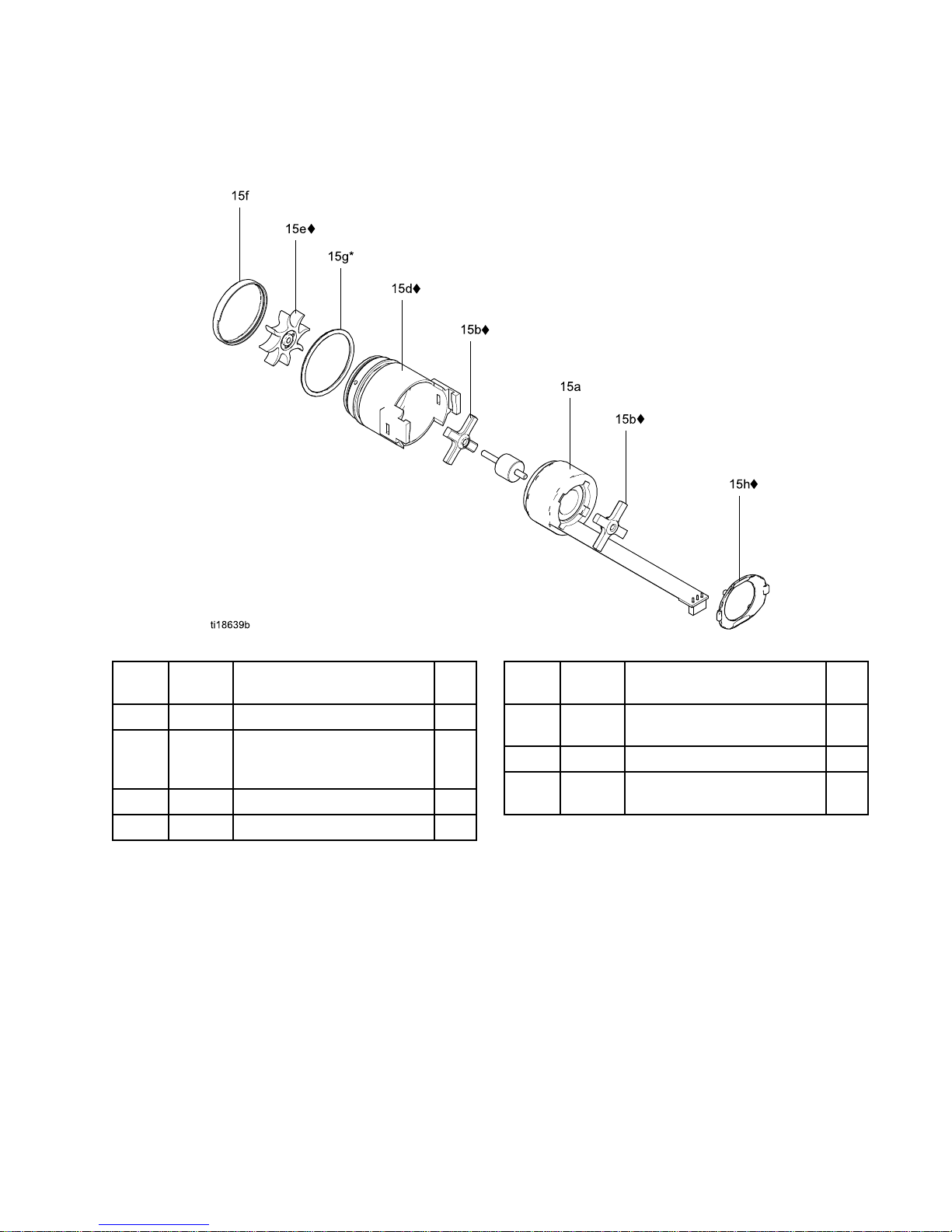
Parts
Alternator Alternator
Alternator
Assembly Assembly
Assembly
Part Part
Part
No. No.
No.
24N664 24N664
24N664
Alternator Alternator
Alternator
Assembly Assembly
Assembly
Ref. Ref.
Ref.
No. No.
No.
Part Part
Part
No. No.
No.
Description Description
Description
Qty Qty
Qty
15a24N705
COIL,alternator
1
15b♦24N706
BEARINGKIT(includestwo
bearings,item15efan,and
oneitem15hclip)
1
15d♦24N707
HOUSING;includesitem15f
1
15e♦
———
FAN;partofitem15b
1
Ref. Ref.
Ref.
No. No.
No.
Part Part
Part
No. No.
No.
Description Description
Description
Qty Qty
Qty
15f
———
CAP,housing;partofitem
15d
1
15g*
110073
O-RING
1
15h♦24N709
CLIP;packageof5(oneclip
includedwithitem15b)
1
*ThesepartsareincludedinAirSealRepairKit
24N789(purchaseseparately).
♦ThesepartsareincludedinBearingKit24N706
(purchaseseparately).
Partslabeled———arenotavailableseparately.
3A2494D 63
Page 64

Parts
ES ES
ES
On On
On
- --Off Off
Off
and and
and
Fluid Fluid
Fluid
Adjustment Adjustment
Adjustment
Valve Valve
Valve
Part Part
Part
No. No.
No.
24N630 24N630
24N630
ES ES
ES
On-Off On-Off
On-Off
and and
and
Fluid Fluid
Fluid
Adjustment Adjustment
Adjustment
Valve Valve
Valve
Ref. Ref.
Ref.
No. No.
No.
Part Part
Part
No. No.
No.
Description Description
Description
Qty Qty
Qty
26a
———
HOUSING,valve
1
26b*
15D371
O-RING
4
26c
———
PISTON,valve
1
26f
24N649
LEVER,ESon-off
1
26g
———
SCREW,set,sockethead
2
Ref. Ref.
Ref.
No. No.
No.
Part Part
Part
No. No.
No.
Description Description
Description
Qty Qty
Qty
26h24N631PLATE,retaining1
26j24N648
KNOB,adjustment,uid
1
26m*
113746
O-RING
2
26p
———
SCREW,captive
1
*ThesepartsareincludedinAirSealRepairKit
24N789(purchaseseparately).
Partslabeled———arenotavailableseparately.
64 3A2494D
Page 65

Parts
Fan Fan
Fan
Air Air
Air
Adjustment Adjustment
Adjustment
Valve Valve
Valve
Assembly Assembly
Assembly
Part Part
Part
No. No.
No.
24N634 24N634
24N634
Fan Fan
Fan
Air Air
Air
Adjustment Adjustment
Adjustment
Valve Valve
Valve
Assembly Assembly
Assembly
(shown) (shown)
(shown)
Part Part
Part
No. No.
No.
24N732 24N732
24N732
Fan Fan
Fan
Air Air
Air
Adjustment Adjustment
Adjustment
Valve Valve
Valve
Assembly Assembly
Assembly
(for (for
(for
round round
round
spray spray
spray
guns, guns,
guns,
not not
not
shown) shown)
shown)
Ref. Ref.
Ref.
No. No.
No.
Part Part
Part
No. No.
No.
Description Description
Description
Qty Qty
Qty
30a
———
NUT,valve1
———
STEM,valve
1
30b
———
STEM,valve;roundsprayonly
1
30c*
111504
O-RING
1
30d24N646
RING,retaining;packageof6
1
*ThesepartsareincludedinAirSealRepairKit
24N789(purchaseseparately).
Partslabeled———arenotavailableseparately.
Atomizing Atomizing
Atomizing
Air Air
Air
Restrictor Restrictor
Restrictor
Valve Valve
Valve
Assembly Assembly
Assembly
Part Part
Part
No. No.
No.
24T304 24T304
24T304
Atomizing Atomizing
Atomizing
Air Air
Air
Restrictor Restrictor
Restrictor
Valve Valve
Valve
Assembly Assembly
Assembly
(shown) (shown)
(shown)
Part Part
Part
No. No.
No.
24N733 24N733
24N733
Atomizing Atomizing
Atomizing
Air Air
Air
Restrictor Restrictor
Restrictor
Valve Valve
Valve
Assembly Assembly
Assembly
(for (for
(for
round round
round
spray spray
spray
guns, guns,
guns,
not not
not
shown) shown)
shown)
Ref. Ref.
Ref.
No. No.
No.
Part Part
Part
No. No.
No.
Description Description
Description
Qty Qty
Qty
29a
———
HOUSING,valve
1
———
BODY,valve
1
29b
———
BODY,valve;roundsprayonly
1
29c*
111516
O-RING
1
29d118907
RING,retaining
1
29e
———
STEM,valve
1
29f
———
KNOB,shaft;roundsprayonly
1
29g
———
SETSCREW,knob;round
sprayonly
1
*ThesepartsareincludedinAirSealRepairKit
24N789(purchaseseparately).
Partslabeled———arenotavailableseparately.
3A2494D 65
Page 66

Parts
Smart Smart
Smart
Module Module
Module
Assembly Assembly
Assembly
Part Part
Part
No. No.
No.
24N756 24N756
24N756
Smart Smart
Smart
Module Module
Module
Assembly Assembly
Assembly
Ref. Ref.
Ref.
No. No.
No.
Part Part
Part
No. No.
No.
Description Description
Description
Qty Qty
Qty
31a
———
CARTRIDGE
1
31b24P433
GASKET
1
31c24N787
SWITCH,ESHI/LO
1
31d♦
———
SCREW
3
31e♦
———
SCREW,pivot
1
31f
112319
O-RING
1
Partslabeled———arenotavailableseparately.
♦ThesepartsareincludedinSmartModuleScrew
Kit24N757(purchaseseparately).
66 3A2494D
Page 67

Parts
High High
High
Conductivity Conductivity
Conductivity
Fluid Fluid
Fluid
Tube Tube
Tube
Assembly Assembly
Assembly
Part Part
Part
No. No.
No.
24N627 24N627
24N627
40 40
40
kV kV
kV
High High
High
Conductivity Conductivity
Conductivity
Fluid Fluid
Fluid
Tube Tube
Tube
Assembly Assembly
Assembly
Includesitems14a-14c
Part Part
Part
No. No.
No.
24N628 24N628
24N628
60 60
60
kV kV
kV
High High
High
Conductivity Conductivity
Conductivity
Fluid Fluid
Fluid
Tube Tube
Tube
Assembly Assembly
Assembly
Includesitems14a-14c
Part Part
Part
No. No.
No.
24N629 24N629
24N629
85 85
85
kV kV
kV
High High
High
Conductivity Conductivity
Conductivity
Fluid Fluid
Fluid
Tube Tube
Tube
Assembly Assembly
Assembly
Includesitems14a-14c
Ref. Ref.
Ref.
No. No.
No.
Part Part
Part
No. No.
No.
Description Description
Description
Qty Qty
Qty
14a**
———
ADAPTER,bracket,handle1
14b**
———
FERRULE2
14c**
———
NUT,bracket,handle1
**Includedin24N735HCAdapterKit.
Partslabeled———arenotavailableseparately.
3A2494D 67
Page 68

AirCapsandFluidNozzles
Air Air
Air
Caps Caps
Caps
and and
and
Fluid Fluid
Fluid
Nozzles Nozzles
Nozzles
Fluid Fluid
Fluid
Nozzle Nozzle
Nozzle
Selection Selection
Selection
Chart Chart
Chart
Toreducetheriskofaninjury,followthe
PressureReliefProcedure,page27,before
removingorinstallingauidnozzleand/oraircap.
Fluid Fluid
Fluid
Nozzle Nozzle
Nozzle
Part Part
Part
No. No.
No.
Color Color
Color
Description Description
Description
Orice Orice
Orice
Size Size
Size
mm mm
mm
(in.) (in.)
(in.)
24N613
0.75(.029)
24N614
1.0(.042)
24N615
1.2(.047)
24N616
1.5(.055)
24N617
1.8(.070)
24N618
2.0(.079)
24N619
Black
For
standard
coatings
0.55(.022)
24N620
0.75(.029)
24N621
1.0(.042)
24N622
1.2(.047)
24N623
1.5(.055)
24N624
1.8(.070)
24N625
Blue
With
hardened
seat,for
abrasives
and
metallics
2.0(.079)
Fluid Fluid
Fluid
Nozzle Nozzle
Nozzle
Performance Performance
Performance
Charts Charts
Charts
Usethefollowingproceduretoselecttheproperuid
nozzleforyourapplication.
1.Foreachuidnozzlechart,ndthepointonthe
graphcorrespondingtoyourdesiredowrate
andviscosity.Markthepointoneachgraphwith
apencil.
2.Thethickverticallineineachgraphrepresents
thetargetowrateforthatnozzlesize.Find
thegraphthathasthemarkedpointclosestto
thethickverticalline.Thisistherecommended
nozzlesizeforyourapplication.Signicantly
exceedingthetargetowratemayresultin
lowersprayperformanceduetoexcessiveuid
velocity.
3.Fromthemarkedpoint,moveacrosstothe
verticalscaletondtherequireduidpressure.
Iftherequiredpressureistoohigh,usethenext
largestnozzlesize.Iftheuidpressureistoolow
(<0.35bar,3.5kPa,5psi),usethenextsmallest
nozzlesize.
Key Key
Key
to totoFluid Fluid
Fluid
Nozzle Nozzle
Nozzle
Performance Performance
Performance
Charts Charts
Charts
NOTE: NOTE:
NOTE:
Fluidpressuresaremeasuredatthespray
guninlet.
260CentipoiseFluid
160CentipoiseFluid
70CentipoiseFluid
20CentipoiseFluid
68 3A2494D
Page 69

AirCapsandFluidNozzles
Table Table
Table
5 55. ..Orice Orice
Orice
Size: Size:
Size:
0.75 0.75
0.75
mm mm
mm
(0.030 (0.030
(0.030
in.) in.)
in.)
FLUID FLUID
FLUID
PRES- PRES-
PRESSURE: SURE:
SURE:
bar,
psi
FLUID FLUID
FLUID
FLOW: FLOW:
FLOW:
oz/min,cc/min
Table Table
Table
6 66. ..Orice Orice
Orice
Size: Size:
Size:
1.0 1.0
1.0
mm mm
mm
(0.040 (0.040
(0.040
in.) in.)
in.)
FLUID FLUID
FLUID
PRES- PRES-
PRESSURE: SURE:
SURE:
bar,
psi
FLUID FLUID
FLUID
FLOW: FLOW:
FLOW:
oz/min,cc/min
Table Table
Table
7 77. ..Orice Orice
Orice
Size: Size:
Size:
1.2 1.2
1.2
mm mm
mm
(0.047 (0.047
(0.047
in.) in.)
in.)
FLUID FLUID
FLUID
PRES- PRES-
PRESSURE: SURE:
SURE:
bar,
psi
FLUID FLUID
FLUID
FLOW: FLOW:
FLOW:
oz/min,cc/min
Table Table
Table
8 88. ..Orice Orice
Orice
Size: Size:
Size:
1.5 1.5
1.5
mm mm
mm
(0.059 (0.059
(0.059
in.) in.)
in.)
FLUID FLUID
FLUID
PRES- PRES-
PRESSURE: SURE:
SURE:
bar,
psi
FLUID FLUID
FLUID
FLOW: FLOW:
FLOW:
oz/min,cc/min
Table Table
Table
9 99. ..Orice Orice
Orice
Size: Size:
Size:
1.8 1.8
1.8
mm mm
mm
(0.070 (0.070
(0.070
in.) in.)
in.)
FLUID FLUID
FLUID
PRES- PRES-
PRESSURE: SURE:
SURE:
bar,
psi
FLUID FLUID
FLUID
FLOW: FLOW:
FLOW:
oz/min,cc/min
Table Table
Table
10 10
10
. ..Orice Orice
Orice
Size: Size:
Size:
2.0 2.0
2.0
mm mm
mm
(0.080 (0.080
(0.080
in.) in.)
in.)
FLUID FLUID
FLUID
PRES- PRES-
PRESSURE: SURE:
SURE:
bar,
psi
FLUID FLUID
FLUID
FLOW: FLOW:
FLOW:
oz/min,cc/min
3A2494D 69
Page 70

AirCapsandFluidNozzles
Air Air
Air
Cap Cap
Cap
Selection Selection
Selection
Chart Chart
Chart
Toreducetheriskofaninjury,followthe
PressureReliefProcedure,page27,before
removingorinstallingauidnozzleand/oraircap.
NOTE: NOTE:
NOTE:
Allaircappatternshapesandlengthsinthe
followingchartweremeasuredunderthefollowing
conditions.Patternshapeandlengtharematerial
dependent.
•
Distance to target:
10in.(254mm)
•
Inlet air pressure:
50psi(34kPa,3.4bar)
•
Fan air:
adjustedformaximumwidth
•
Fluid ow rate:
10oz/min(300cc/min)
Part Part
Part
No. No.
No.
(color) (color)
(color)
Pattern Pattern
Pattern
Shape Shape
Shape
Length Length
Length
in. in.
in.
(mm) (mm)
(mm)
Recommended Recommended
Recommended
Fluid Fluid
Fluid
Viscosity, Viscosity,
Viscosity,
in in
in
centipoise centipoise
centipoise
(cp) (cp)
(cp)
at at
at
70°F 70°F
70°F
(21°C)♦ (21°C)♦
(21°C)♦
Recommended Recommended
Recommended
Production Production
Production
Rates Rates
Rates
Transfer Transfer
Transfer
Efciency Efciency
Efciency
Atomiza- Atomiza-
Atomization tion
tion
Cleanli- Cleanli-
Cleanliness ness
ness
24N438
(black)
Round
end
15-17
(381-432)
Lighttomedium
(20–70cp)
Upto15oz/min(450
cc/min)
BetterBest
Good
24N279
(black)
Round
end
14-16
(356-406)
Mediumtoheavy
(70–260cp),and
highsolids(360+cp)
Upto15oz/min(450
cc/min)
BetterBetter
Good
24N376
(black)
24N276
(blue)
24N277
(red)
24N278
(green)
Tapered
end
17-19
(432-483)
Lighttomedium
(20–70cp)
Upto15oz/min(450
cc/min)
BestBetterBetter
24N274
(black)
Tapered
end
12-14
(305-356)
Lighttomedium
(20–70cp)
Upto15oz/min(450
cc/min)
GoodGood
Best
24N275
(black)
Tapered
end
14-16
(356-406)
Lighttomedium
(20–70cp),andhigh
solids(360+cp),
aerospacecoatings
Upto25oz/min(750
cc/min)
Best
Good
Best
24N439
(black)
Tapered
end
11-13
(279-330)
Forusewith2.0mm
nozzles.Mediumto
heavy(70–260cp),
andhighsolids(360+
cp)
Upto20oz/min(600
cc/min)
Good
BestBetter
24N477
(black)
24W279
(green)
Round
end
15-17
(381-432)
Lighttomedium
(20–70cp)
Upto15oz/min(450
cc/min)
BetterBest
Good
24N453
(black)
Round
end
14-16
(356-406)
Lighttomedium
(20–70cp)
Upto15oz/min(450
cc/min)
BetterBetter
Good
♦Centipoise=centistokesxuidspecicgravity.
70 3A2494D
Page 71

AirCapsandFluidNozzles
Air Air
Air
Consumption Consumption
Consumption
Charts Charts
Charts
Key Key
Key
to totoAir Air
Air
Consumption Consumption
Consumption
Charts Charts
Charts
TEST TEST
TEST
CONDITIONS: CONDITIONS:
CONDITIONS:
Fanvalvefullyopen;85kV
gun.
5/16in.x25ft(8mmx
7.6m)hose
5/16in.x50ft(8mmx
15.2m)hose
Table Table
Table
11 11
11
. ..24N438 24N438
24N438
Air Air
Air
Cap Cap
Cap
AIR AIR
AIR
CON- CON-
CON-
SUMPTION SUMPTION
SUMPTION
scfm
WALL WALL
WALL
PRESSURE PRESSURE
PRESSURE
psi
Table Table
Table
12 12
12
. ..24N376, 24N376,
24N376,
24N276, 24N276,
24N276,
24N277, 24N277,
24N277,
and and
and
24N278 24N278
24N278
Air Air
Air
Caps Caps
Caps
AIR AIR
AIR
CON- CON-
CON-
SUMPTION SUMPTION
SUMPTION
scfm
WALL WALL
WALL
PRESSURE PRESSURE
PRESSURE
psi
Table Table
Table
13 13
13
. ..24N439 24N439
24N439
Air Air
Air
Cap Cap
Cap
AIR AIR
AIR
CON- CON-
CON-
SUMPTION SUMPTION
SUMPTION
scfm
WALL WALL
WALL
PRESSURE PRESSURE
PRESSURE
psi
Table Table
Table
14 14
14
. ..24N279 24N279
24N279
Air Air
Air
Cap Cap
Cap
AIR AIR
AIR
CON- CON-
CON-
SUMPTION SUMPTION
SUMPTION
scfm
WALL WALL
WALL
PRESSURE PRESSURE
PRESSURE
psi
3A2494D
71
Page 72

AirCapsandFluidNozzles
Table Table
Table
15 15
15
. ..24N274 24N274
24N274
Air Air
Air
Cap Cap
Cap
AIR AIR
AIR
CON- CON-
CON-
SUMPTION SUMPTION
SUMPTION
scfm
WALL WALL
WALL
PRESSURE PRESSURE
PRESSURE
psi
Table Table
Table
16 16
16
. ..24N275 24N275
24N275
Air Air
Air
Cap Cap
Cap
AIR AIR
AIR
CON- CON-
CON-
SUMPTION SUMPTION
SUMPTION
scfm
WALL WALL
WALL
PRESSURE PRESSURE
PRESSURE
psi
Table Table
Table
17 17
17
. ..24N453 24N453
24N453
Air Air
Air
Cap Cap
Cap
AIR AIR
AIR
CON- CON-
CON-
SUMPTION SUMPTION
SUMPTION
scfm
WALL WALL
WALL
PRESSURE PRESSURE
PRESSURE
psi
Table Table
Table
18 18
18
. ..24N477, 24N477,
24N477,
24W279 24W279
24W279
Air Air
Air
Cap Cap
Cap
AIR AIR
AIR
CON- CON-
CON-
SUMPTION SUMPTION
SUMPTION
scfm
WALL WALL
WALL
PRESSURE PRESSURE
PRESSURE
psi
72
3A2494D
Page 73

RepairKits,RelatedManuals,andAccessories
Repair Repair
Repair
Kits, Kits,
Kits,
Related Related
Related
Manuals, Manuals,
Manuals,
and and
and
Accessories Accessories
Accessories
Gun Gun
Gun
Part Part
Part
No. No.
No.
Description Description
Description
Manual Manual
Manual
Description Description
Description
Repair Repair
Repair
Kits Kits
Kits
Repair Repair
Repair
Kit Kit
Kit
Description Description
Description
24N789
AirSealRepairKit
24N790
FluidSealRepairKit
Allgunsin
thismanual.
40kV,60kV,and85
kVAirSprayGuns
ElectrostaticAir
SprayGuns,
Instructions-Parts
24N706AlternatorBearingRepairKit
Gun Gun
Gun
Accessories Accessories
Accessories
Part Part
Part
No. No.
No.
Description Description
Description
105749
CleaningBrush.
111265
Non-siliconeLubricant,4oz(113g).
116553
DielectricGrease.1oz(30ml)
24N318
RoundSprayKit.Toconverta
standardairsprayguntoaround
sprayaircap.Seemanual3A2498.
24N603
GunCovers.For40kVand60kV
guns.Boxof10.
24N604
GunCovers.For85kVguns.Box
of10.
24N636
LowProleAtomizingAirRestrictor
Valve
24N642
BallSwivel,forgunairinlet.1/4
npsm(left-handthread)
24N704
ElectrodeReplacementNeedlefor
AbrasiveMaterials.Blue.
24N758
DisplayCovers.KeepsSmartdisplay
clean.Packageof5.
Part Part
Part
No. No.
No.
Description Description
Description
24P170MetalTriggerKit.
24P171FourFingerTriggerKit.Toconvert
ProXpairspraygunstoafournger
trigger.
24P172
QuickAdjustValve.Forquick
changeoffansize.
185105
Non-swivelAirInlet;1/4–18npsm(m)
(left-handthread)
185493
AirHoseAdapter;1/4npt(m)x
1/4–18npsm(m)(left-handthread)
112534
AirLineQuickDisconnectFitting.
24N627,
24N628,
24N629
HighConductivityConversion
Kits.ToconvertastandardPro
XpairsprayguntoanHCgun.
SeeHighConductivityFluidTube
Assembly,page67.
3A2494D 73
Page 74

RepairKits,RelatedManuals,andAccessories
Operator Operator
Operator
Accessories Accessories
Accessories
Part Part
Part
No. No.
No.
Description Description
Description
117823
ConductiveGloves,boxof12(small)
117824
ConductiveGloves,boxof12
(medium)
117825
ConductiveGloves,boxof12(large)
24N520
ComfortGrip.Snap-ongrip
increaseshandlesizetoreduce
operatorfatigue.Mediumsize.
24N521
ComfortGrip.Snap-ongrip
increaseshandlesizetoreduce
operatorfatigue.Largesize.
System System
System
Accessories Accessories
Accessories
Part Part
Part
No. No.
No.
Description Description
Description
222011
GroundWireandClamp.
16P802
EnglishWarningSign.Availableat
nochargefromGraco.
16P798
EnglishDailyCareSign.
16P799
EnglishSetupSign
24N528
GunFlushBoxAdapterfor60and
85kVguns.Toconvertexistinggun
ushboxestoholdProXpguns.
24N529
GunFlushBoxAdapterfor40kV
guns.Toconvertexistinggunush
boxestoholdProXpguns.
24P312
GunWasherKit.Toconvertexisting
gunwasherstocleanProXpguns.
Test Test
Test
Equipment Equipment
Equipment
Part Part
Part
No. No.
No.
Description Description
Description
241079Megohmmeter.500Voutput,
0.01–2000megohms.Usefor
groundcontinuityandgunresistance
tests.Not Not
Not
for for
for
use use
use
in ininhazardous hazardous
hazardous
areas. areas.
areas.
722886
PaintResistanceMeter.Useforuid
resistivitytest.Seemanual307263.
Not Not
Not
for for
for
use use
use
in ininhazardous hazardous
hazardous
areas. areas.
areas.
722860
PaintProbe.Useforuidresistivity
test.Seemanual307263.Not Not
Not
for for
for
use use
use
in ininhazardous hazardous
hazardous
areas. areas.
areas.
245277TestFixture,HighVoltageProbe,
andkVMeter.Usetotestthe
electrostaticvoltageofthegun,and
theconditionofthealternatorand
powersupplywhenbeingserviced.
Seemanual309455.Alsorequires
24R038ConversionKit.
24R038
VoltageTesterConversionKit.
Convertsthe245277TestFixturefor
usewiththeProXpGunalternator.
Seemanual406999.
74
3A2494D
Page 75

RepairKits,RelatedManuals,andAccessories
Hoses Hoses
Hoses
Grounded Grounded
Grounded
Air Air
Air
Hoses Hoses
Hoses
100 psi (0.7 MPa, 7 bar) Maximum Working Pressure
0.315in.(8mm)ID;1/4npsm(f)x1/4npsm(f)left-handthread
Part Part
Part
No. No.
No.
Description Description
Description
AirFlex AirFlex
AirFlex
Flexible Flexible
Flexible
Grounded Grounded
Grounded
Air Air
Air
Hose Hose
Hose
(Gray) (Gray)
(Gray)
244963
6ft(1.8m)
244964
15ft(4.6m)
244965
25ft(7.6m)
24N736
25ft(7.6m),with112534Quick
Disconnect
244966
36ft(11m)
24N737
36ft(11m),with112534Quick
Disconnect
244967
50ft(15m)
24N738
50ft(15m),with112534Quick
Disconnect
244968
75ft(23m)
244969
100ft(30.5m)
Part Part
Part
No. No.
No.
Description Description
Description
Standard Standard
Standard
Grounded Grounded
Grounded
Air Air
Air
Hose Hose
Hose
(Gray) (Gray)
(Gray)
223068
6ft(1.8m)
223069
15ft(4.6m)
223070
25ft(7.6m)
223071
36ft(11m)
223072
50ft(15m)
223073
75ft(23m)
223074
100ft(30.5m)
0.375 0.375
0.375
in. in.
in.
(10 (10
(10
mm) mm)
mm)
ID; ID;
ID;
3/8 3/8
3/8
npsm(f) npsm(f)
npsm(f)
x xx1/4 1/4
1/4
npsm(f) npsm(f)
npsm(f)
left left
left
- --hand hand
hand
thread thread
thread
24A225
50ft(15m)
24A226
75ft(23m)
Part Part
Part
No. No.
No.
Description Description
Description
Grounded Grounded
Grounded
Air Air
Air
Hose Hose
Hose
with with
with
stainless stainless
stainless
steel steel
steel
braid braid
braid
ground ground
ground
path path
path
(Red) (Red)
(Red)
235068
6ft(1.8m)
235069
15ft(4.6m)
235070
25ft(7.6m)
235071
36ft(11m)
235072
50ft(15m)
235073
75ft(23m)
235074
100ft(30.5m)
Fluid Fluid
Fluid
Hoses Hoses
Hoses
225 psi (1.4 MPa, 14 bar) Maximum Working
Pressure
1/4in.(6mm)ID;3/8npsm(fbe);nylon;FMapproved.
Part Part
Part
No. No.
No.
Description Description
Description
215637
25ft(7.6m)
215638
50ft(15m)
High High
High
Conductivity Conductivity
Conductivity
Fluid Fluid
Fluid
Hose Hose
Hose
Forhighconductivitymaterials.For For
For
60 60
60
kV kV
kV
guns guns
guns
only. only.
only.
100 psi (0.7 MPa, 7 bar) Maximum Working Pressure
1/4in.(6mm)ID;3/8npsm(f)x5/8–20(m);ptfe;FM
approved.
Part Part
Part
No. No.
No.
Description Description
Description
24N994
26.8ft(8.2m)
3A2494D 75
Page 76

Dimensions
Dimensions Dimensions
Dimensions
Gun Gun
Gun
Model Model
Model
A, A,
A,
in. in.
in.
(mm) (mm)
(mm)
B, B,
B,
in. in.
in.
(mm) (mm)
(mm)
C, C,
C,
in. in.
in.
(mm) (mm)
(mm)
Weight, Weight,
Weight,
oz oz
oz
(g) (g)
(g)
L40T10
8.7(221)9.2(234)2.4(61)19.8(562)
L40T14
8.7(221)9.2(234)2.4(61)20.0(568)
L40T15
8.7(221)9.2(234)2.4(61)20.5(582)
L40T16
8.7(221)9.2(234)2.4(61)20.5(582)
L60T10
9.5(241)9.2(234)2.4(61)21.1(600)
L60T11
8.7(221)9.2(234)2.4(61)21.1(600)
L60T12
9.5(241)9.2(234)2.4(61)21.1(600)
L60T16
9.5(241)9.2(234)2.4(61)22.6(642)
L60M10
9.5(241)10(254)2.4(61)23.7(673)
L60M12
9.5(241)10(254)2.4(61)23.7(673)
L60M16
9.5(241)10(254)2.4(61)25.4(720)
L85T10
10.5(267)9.2(234)2.4(61)23.8(676)
L85T16
10.5(267)9.2(234)2.4(61)25.5(725)
L85M10
10.5(267)10(254)2.4(61)26.3(746)
L85M16
10.5(267)10(254)2.4(61)28.0(794)
76 3A2494D
Page 77

TechnicalData
Technical Technical
Technical
Data Data
Data
Electrostatic Electrostatic
Electrostatic
Air Air
Air
Spray Spray
Spray
Guns Guns
Guns
U.S. U.S.
U.S.
Metric Metric
Metric
MaximumWorkingFluidPressure100psi0.7MPa,7.0bar
MaximumWorkingAirPressure100psi0.7MPa,7.0bar
MinimumAirPressureatGunInlet
45psi0.32MPa,3.2bar
MaximumFluidOperating
Temperature
120°F48°C
PaintResistivityRange
3megohm/cmtoinnity.Foratableofelectrostaticresultsatdifferent
resistancelevels,seeCheckFluidResistivity,page26.
AirInletFitting
1/4npsm(m)left-handthread
FluidInletFitting
3/8npsm(m)
OutputVoltage
ProXp40Models:40kV
ProXp60Models:60kV
ProXp85Models:85kV
MaximumCurrentDraw
125microamperes
SoundPower(measuredperISO
Standard9216)
at40psi:90.4dB(A)
at100psi:105.4dB(A)
at0.28MPa,2.8bar:90.4dB(A)
at0.7MPa,7.0bar:105.4dB(A)
SoundPressure(measured1m
fromgun)
at40psi:87.0dB(A)
at100psi:99.0dB(A)
at0.28MPa,2.8bar:87.0dB(A)
at0.7MPa,7.0bar:99.0dB(A)
WettedPartsPEEK,UHMWPE,FEP,PTFE,acetal,nylon,polyethylene
3A2494D
77
Page 78

Graco Graco
Graco
Pro Pro
Pro
Xp Xp
Xp
Warranty Warranty
Warranty
GracowarrantsallequipmentreferencedinthisdocumentwhichismanufacturedbyGracoandbearingitsname
tobefreefromdefectsinmaterialandworkmanshiponthedateofsaletotheoriginalpurchaserforuse.Withthe
exceptionofanyspecial,extended,orlimitedwarrantypublishedbyGraco,Gracowill,foraperiodoftwelvemonths
fromthedateofsale,repairorreplaceanypartoftheequipmentdeterminedbyGracotobedefective.However,any
deciencyinthebarrel,handle,trigger,hook,internalpowersupply,andalternator(excludingturbinebearings)willbe
repairedorreplacedforthirty-sixmonthsfromthedateofsale.Thiswarrantyappliesonlywhentheequipmentis
installed,operatedandmaintainedinaccordancewithGraco’swrittenrecommendations.
Thiswarrantydoesnotcover,andGracoshallnotbeliableforgeneralwearandtear,oranymalfunction,damage
orwearcausedbyfaultyinstallation,misapplication,abrasion,corrosion,inadequateorimpropermaintenance,
negligence,accident,tampering,orsubstitutionofnon-Gracocomponentparts.NorshallGracobeliablefor
malfunction,damageorwearcausedbytheincompatibilityofGracoequipmentwithstructures,accessories,
equipmentormaterialsnotsuppliedbyGraco,ortheimproperdesign,manufacture,installation,operationor
maintenanceofstructures,accessories,equipmentormaterialsnotsuppliedbyGraco.
Thiswarrantyisconditionedupontheprepaidreturnoftheequipmentclaimedtobedefectivetoanauthorized
Gracodistributorforvericationoftheclaimeddefect.Iftheclaimeddefectisveried,Gracowillrepairorreplace
freeofchargeanydefectiveparts.Theequipmentwillbereturnedtotheoriginalpurchasertransportationprepaid.
Ifinspectionoftheequipmentdoesnotdiscloseanydefectinmaterialorworkmanship,repairswillbemadeata
reasonablecharge,whichchargesmayincludethecostsofparts,labor,andtransportation.
THIS THIS
THIS
WARRANTY WARRANTY
WARRANTY
IS ISISEXCLUSIVE, EXCLUSIVE,
EXCLUSIVE,
AND AND
AND
IS ISISIN IN
IN
LIEU LIEU
LIEU
OF OF
OF
ANY ANY
ANY
OTHER OTHER
OTHER
WARRANTIES, WARRANTIES,
WARRANTIES,
EXPRESS EXPRESS
EXPRESS
OR OR
OR
IMPLIED, IMPLIED,
IMPLIED,
INCLUDING INCLUDING
INCLUDING
BUT BUT
BUT
NOT NOT
NOT
LIMITED LIMITED
LIMITED
TO TO
TO
WARRANTY WARRANTY
WARRANTY
OF OF
OF
MERCHANTABILITY MERCHANTABILITY
MERCHANTABILITY
OR OR
OR
WARRANTY WARRANTY
WARRANTY
OF OF
OF
FITNESS FITNESS
FITNESS
FOR FOR
FOR
A A
A
PARTICULAR PARTICULAR
PARTICULAR
PURPOSE. PURPOSE.
PURPOSE.
Graco’ssoleobligationandbuyer’ssoleremedyforanybreachofwarrantyshallbeassetforthabove.Thebuyer
agreesthatnootherremedy(including,butnotlimitedto,incidentalorconsequentialdamagesforlostprots,lost
sales,injurytopersonorproperty,oranyotherincidentalorconsequentialloss)shallbeavailable.Anyactionfor
breachofwarrantymustbebroughtwithintwo(2)yearsofthedateofsale.
GRACO GRACO
GRACO
MAKES MAKES
MAKES
NO NO
NO
WARRANTY, WARRANTY,
WARRANTY,
AND AND
AND
DISCLAIMS DISCLAIMS
DISCLAIMS
ALL ALL
ALL
IMPLIED IMPLIED
IMPLIED
WARRANTIES WARRANTIES
WARRANTIES
OF OF
OF
MERCHANTABILITY MERCHANTABILITY
MERCHANTABILITY
AND AND
AND
FITNESS FITNESS
FITNESS
FOR FOR
FOR
A AAPARTICULAR PARTICULAR
PARTICULAR
PURPOSE, PURPOSE,
PURPOSE,
IN ININCONNECTION CONNECTION
CONNECTION
WITH WITH
WITH
ACCESSORIES, ACCESSORIES,
ACCESSORIES,
EQUIPMENT, EQUIPMENT,
EQUIPMENT,
MATERIALS MATERIALS
MATERIALS
OR OR
OR
COMPONENTS COMPONENTS
COMPONENTS
SOLD SOLD
SOLD
BUT BUT
BUT
NOT NOT
NOT
MANUFACTURED MANUFACTURED
MANUFACTURED
BY BY
BY
GRACO. GRACO.
GRACO.
Theseitemssold,butnotmanufacturedby
Graco(suchaselectricmotors,switches,hose,etc.),aresubjecttothewarranty,ifany,oftheirmanufacturer.Graco
willprovidepurchaserwithreasonableassistanceinmakinganyclaimforbreachofthesewarranties.
InnoeventwillGracobeliableforindirect,incidental,specialorconsequentialdamagesresultingfromGraco
supplyingequipmenthereunder,orthefurnishing,performance,oruseofanyproductsorothergoodssoldhereto,
whetherduetoabreachofcontract,breachofwarranty,thenegligenceofGraco,orotherwise.
FORGRACOCANADACUSTOMERS
ThePartiesacknowledgethattheyhaverequiredthatthepresentdocument,aswellasalldocuments,noticesand
legalproceedingsenteredinto,givenorinstitutedpursuantheretoorrelatingdirectlyorindirectlyhereto,bedrawn
upinEnglish.LespartiesreconnaissentavoirconvenuquelarédactionduprésentedocumentseraenAnglais,
ainsiquetousdocuments,avisetprocéduresjudiciairesexécutés,donnésouintentés,àlasuitedeouenrapport,
directementouindirectement,aveclesprocéduresconcernées.
Graco Graco
Graco
Information Information
Information
To To
To
place place
place
an an
an
order, order,
order,
contactyourGracoDistributororcalltoidentifythenearestdistributor.
Phone: Phone:
Phone:
612-623-6921or ororToll Toll
Toll
Free: Free:
Free:
1-800-328-0211Fax: Fax:
Fax:
612-378-3505
Allwrittenandvisualdatacontainedinthisdocumentreectsthelatestproductinformationavailableatthetimeofpublication.
Gracoreservestherighttomakechangesatanytimewithoutnotice.
Forpatentinformation,seewww.graco.com/patents.
OriginalInstructions.ThismanualcontainsEnglish,MM3A2494
Graco Graco
Graco
Headquarters: Headquarters:
Headquarters:
Minneapolis
International International
International
Ofces: Ofces:
Ofces:
Belgium,China,Japan,Korea
GRACO GRACO
GRACO
INC. INC.
INC.
AND AND
AND
SUBSIDIARIES SUBSIDIARIES
SUBSIDIARIES
• ••P.O. P.O.
P.O.
BOX BOX
BOX
1441 1441
1441
• ••MINNEAPOLIS, MINNEAPOLIS,
MINNEAPOLIS,
MN MN
MN
55440-1441 55440-1441
55440-1441
• ••USA USA
USA
Copyright Copyright
Copyright
2012, 2012,
2012,
Graco Graco
Graco
Inc. Inc.
Inc.
All All
All
Graco Graco
Graco
manufacturing manufacturing
manufacturing
locations locations
locations
are are
are
registered registered
registered
to totoISO ISO
ISO
9001. 9001.
9001.
www.graco.com
RevisionD,June2014
 Loading...