

Page 1
Instructions-Parts
Pro
Pro Pro
Air
Air Air
For
For For
For
For For
use
use use
100psi(0.7MPa,7.0bar)Maximum
FluidWorkingPressure
100psi(0.7MPa,7.0bar)MaximumAir
WorkingPressure
Seepage3formodelpartnumbersand
approvalinformation.
Xp™
Xp™ Xp™
Spray
Spray Spray
use
use use
use
use use
only.
only. only.
Class
in ininClass Class
Group
in ininGroup Group
Important
Important Important
Thisequipmentcouldpresenthazardsifnotoperatedaccordingto
theinformationinthismanual.Readallwarningsandinstructionsin
thismanualbeforeusingtheequipment.Save Save
Electrostatic
Electrostatic Electrostatic
Gun
Gun Gun
Div.
I, I,I,Div. Div.
II,
II, II,
Safety
Safety Safety
Hazardous
I IIHazardous Hazardous
Zone
Zone Zone
Explosive
1 11Explosive Explosive
Instructions
Instructions Instructions
3A2494P
EN
Locations
Locations Locations
Atmosphere
Atmosphere Atmosphere
using
Group
using using
Group Group
Locations
Locations Locations
Save
these
instructions.
these these
instructions. instructions.
materials.
D DDmaterials. materials.
using
Group
using using
Group Group
IIA
materials.
IIA IIA
materials. materials.
For
professional
For For
professional professional
PROVENQUALITY.LEADINGTECHNOLOGY.
Page 2

Contents
Contents Contents
Models...............................................................3
Approvals...........................................................7
RelatedManuals................................................7
Warnings...........................................................8
GunOverview....................................................11
HowtheElectrostaticSprayGun
Works............................................11
Controls,Indicators,andComponents...........12
SmartGuns.................................................13
Installation..........................................................18
WarningSign...............................................18
VentilatetheSprayBooth.............................18
AirSupplyLine............................................19
FluidSupplyLine.........................................19
Grounding...................................................21
GunSetup..........................................................25
GunSetupProcedure...................................25
SoftSprayGunSetupProcedure..................28
HVLPGunSetupProcedure.........................29
RoundSprayGunSetupProcedure..............31
AbrasiveMaterialGunSetup
Procedure......................................33
CheckGunElectricalGrounding...................34
CheckFluidResistivity.................................35
CheckFluidViscosity...................................35
FlushBeforeUsingEquipment......................35
Operation...........................................................36
PressureReliefProcedure............................36
Startup........................................................37
Shutdown....................................................37
Maintenance......................................................38
DailyCareandCleaningChecklist................38
Flushing......................................................38
CleantheGunDaily.....................................40
DailySystemCare.......................................41
ElectricalTests...................................................42
TestGunResistance....................................42
TestPowerSupplyResistance.....................43
TestElectrodeResistance............................43
Troubleshooting..................................................44
SprayPatternTroubleshooting......................44
GunOperationTroubleshooting....................45
ElectricalTroubleshooting............................46
Repair................................................................47
PreparetheGunforService.........................47
AirCapandNozzleReplacement..................48
ElectrodeReplacement................................49
FluidPackingRodRemoval..........................50
PackingRodRepair.....................................50
BarrelRemoval............................................52
BarrelInstallation.........................................52
PowerSupplyRemovaland
Replacement..................................53
AlternatorRemovalandReplacement...........54
FluidTubeRemovalandReplacement...........56
FanAirAdjustmentValveRepair..................57
AtomizingAirRestrictorValveRepair............58
ESOn-OffandFluidAdjustmentValve
Repair............................................59
AirValveRepair...........................................60
SmartModuleReplacement..........................61
AirSwivelandExhaustValve
Replacement..................................62
Parts..................................................................63
GunModelswithStandardDisplay................63
GunModelswithSmartDisplay....................66
PackingRodAssembly.................................69
AlternatorAssembly.....................................70
ESOn-OffandFluidAdjustmentValve...........71
FanAirAdjustmentValveAssembly..............72
QuickAdjustFanValveAssembly.................72
AtomizingAirRestrictorValve
Assembly.......................................73
SmartModuleAssembly...............................74
RoundSprayAssembly................................75
HighConductivityFluidTubeAssembly:40
kV..................................................77
HighConductivityFluidTubeAssembly:60
kVand85kV..................................78
FluidNozzles.....................................................79
FluidNozzleSelectionChart.........................79
FluidNozzlePerformanceCharts..................80
AirCaps.............................................................82
AirCapSelectionGuide...............................82
AirConsumptionCharts...............................87
ElectrodeSelectionChart....................................88
RepairKitsandAccessories................................89
GunAccessories..........................................89
InlineFluidFilterKitAccessories...................90
OperatorAccessories...................................90
SystemAccessories.....................................90
Signs..........................................................91
TestEquipment...........................................91
Hoses.........................................................92
Dimensions........................................................93
TechnicalSpecications......................................94
CaliforniaProposition65.....................................94
2
3A2494P
Page 3

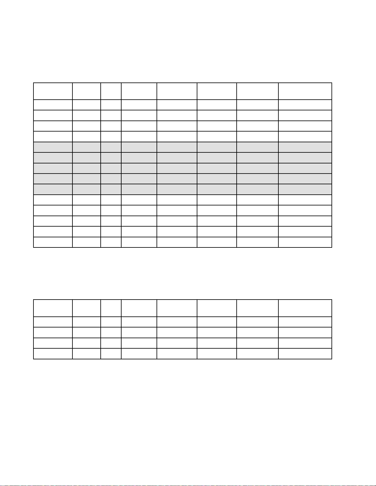
Models
Models
Models Models
General
General General
Equippedwithstandardelectrode,nozzle,aircapanduidtube.ForapplyingaClassAnishwithstandard
andspecialtycoatings.
Part
Part Part
L40M10A40
L40T10
L40T12A40
L60M10
L60M12
L60T10
L60T12
L60T21A60
L85M10
L85M12A85
L85T10
L85T12A85
L85T50*
Gun
Gun Gun
No.
No. No.
Models
Models Models
Series
Series Series
C
C
C
C
C
C
C
A85
kV
kV kV
40
60
60
60
60
85
85
Display
Display Display
SmartStd1.5StdStdStd
StdStd1.5StdStdStd
StdStd1.2StdStdStd
SmartStd1.5StdStdStd
SmartStd1.2StdStdStd
StdStd1.5StdStdStd
StdStd1.2StdStdStd
StdStd1.0StdStdStd
SmartStd1.5StdStdStd
SmartStd1.2StdStdStd
StdStd1.5StdStdStd
StdStd1.2StdStdStd
StdStd1.5StdStdStd
Electrode
Electrode Electrode
Nozzle
Nozzle Nozzle
(mm)
(mm) (mm)
Air
Cap
Air Air
Cap Cap
Fluid
Tube
Fluid Fluid
Tube Tube
*Equippedwithaquick-adjustfanvalve
3A2494P3
Page 4
Models
High
High High
EquippedwithalongerHighConductivityuidtubeforsprayinglowerresistivitymaterial.Mostmodelsare
alsoequippedwithhighwearelectrode,precisionhighwearnozzle,andstandardaircap.Forapplyinga
classAnishwithabrasiveandmetalliccoatings.
Conductivity
Conductivity Conductivity
Part
No.
Part Part
No. No.
L40M16A40
L40T13B40
L40T16
L40T26A40
L60M26A60
L60M16
L60T26A60
L60T13B60
L60T16
L85M16
L85M26A85
L85T16
Series
Series Series
C
C
C
C
C
Gun
Gun Gun
Models
Models Models
kV
kV kV
40
60
60
85
85
Display
Display Display
Smart
Std
Std
Std
Smart
Smart
Std
Std
Std
Smart
Smart
Std
Electrode
Electrode Electrode
HW1.5PHW
HW
HW1.5PHW
HW1.2PHW
HW1.2PHW
HW1.5PHW
HW1.2PHW
HW
HW1.5PHW
HW1.5PHW
HW1.2PHW
HW1.5PHW
Nozzle
Nozzle Nozzle
(mm)
(mm) (mm)
1.5StdStdHC
1.5StdStdHC
Air
Cap
Air Air
Cap Cap
StdHC
StdHC
StdHC
StdHC
StdHC
StdHC
StdHC
StdHC
StdHC
StdHC
Fluid
Tube
Fluid Fluid
Tube Tube
L85T26A85
L85T56*
*Equippedwithaquick-adjustfanvalve
kV
Booster
kV kV
Booster Booster
The40kVBoosterprovidesthetransferefciencyofa60kVguninasmaller,morecompactsize.
Part
No.
Part Part
No. No.
L40M14A40
L40M15A40
L40T14
L40T15
A85
Gun
Gun Gun
Series
Series Series
C
C
Models
Models Models
kV
kV kV
40
40
Std
Std
Display
Display Display
SmartStd1.5StdStdStd
Smart
StdStd1.5StdStdStd
Std
HW1.2PHW
HW1.5PHW
Electrode
Electrode Electrode
HW1.5PHW
HW1.5PHW
StdHC
StdHC
Nozzle
Nozzle Nozzle
(mm)
(mm) (mm)
Air
Cap
Air Air
Cap Cap
StdHC
StdHC
Fluid
Tube
Fluid Fluid
Tube Tube
4
3A2494P
Page 5
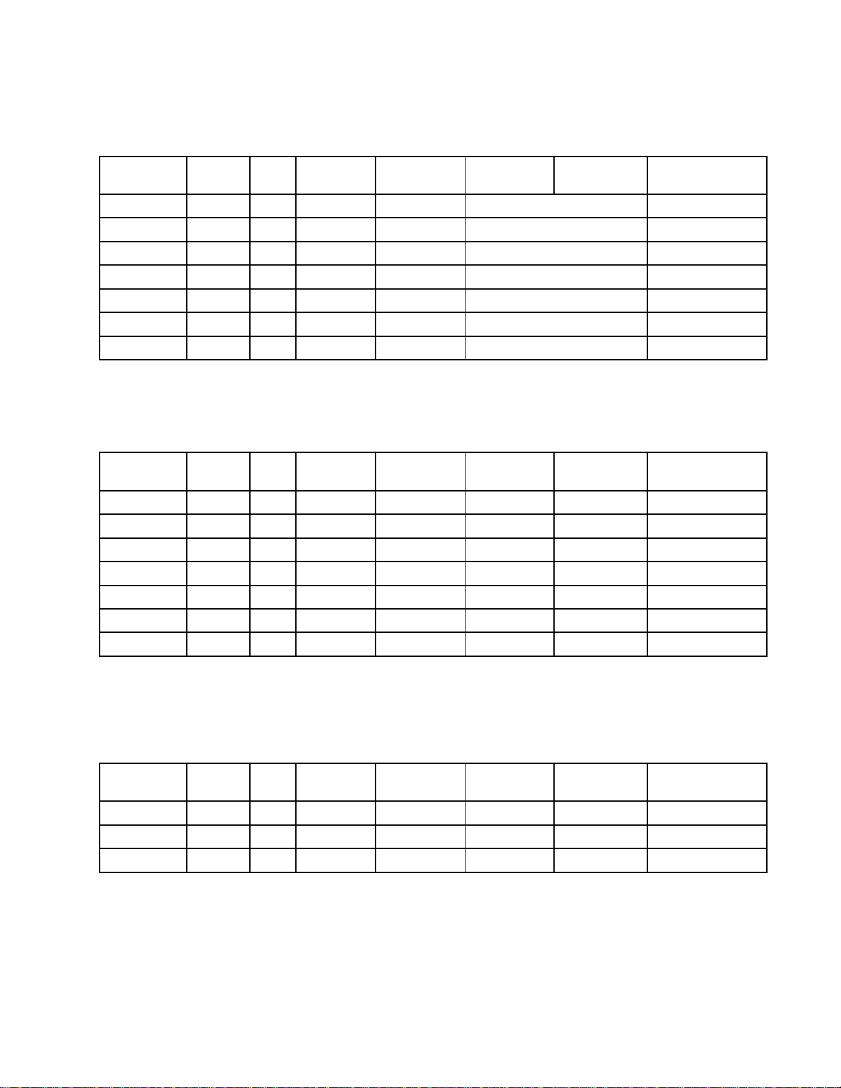
Models
Round
Round Round
Equippedwithroundspraynozzleandaircap.Forroundspraypatternapplications.
Part
Part Part
L40T31A40
L40T32A40
L60T11
L60T31A60
L60T32A60
L85T31A85
L85T32A85
Soft
Soft Soft
Equippedwithsoftsprayaircap.ForapplyingaclassAnishtosmall,lightweightparts.
Part
Part Part
L40T71A40
Spray
Spray Spray
No.
No. No.
Spray
Spray Spray
No.
No. No.
Gun
Gun Gun
Series
Series Series
C
Gun
Gun Gun
Series
Series Series
Models
Models Models
kV
kV kV
60
Models
Models Models
kV
kV kV
Display
Display Display
StdStdSmallPatternStd
StdStd
StdStd
StdStdSmallPatternStd
StdStd
StdStdSmallPatternStd
StdStd
Display
Display Display
StdStd1.0StdSoftSprayStd
Electrode
Electrode Electrode
Electrode
Electrode Electrode
Nozzle
Nozzle Nozzle
(mm)
(mm) (mm)
MediumPattern
LargePattern
MediumPattern
MediumPattern
Nozzle
Nozzle Nozzle
(mm)
(mm) (mm)
Fluid
Air
Cap
Air Air
Cap Cap
Air
Cap
Air Air
Cap Cap
Tube
Fluid Fluid
Tube Tube
Std
Std
Std
Std
Fluid
Tube
Fluid Fluid
Tube Tube
L60M71A60
L60M72A60
L60T71A60
L60T72A60
L85M71A85
L85T71A85
Aerospace
Aerospace Aerospace
Equippedwithaerospaceaircap,highwearelectrode,andprecisionhighwearnozzle.Forapplyinghigh
solidsandaerospacecoatings.
Part
No.
Part Part
No. No.
L85T73A85
L85T75A85
L85T78A85
Gun
Gun Gun
Series
Series Series
Models
Models Models
kV
kV kV
SmartStd1.0StdSoftSprayStd
SmartStd1.2StdSoftSprayStd
StdStd1.0StdSoftSprayStd
StdStd1.2StdSoftSprayStd
SmartStd1.0StdSoftSprayStd
StdStd1.0StdSoftSprayStd
Display
Display Display
Std
Std
Std
Electrode
Electrode Electrode
HW1.2PHW
HW1.5PHW
HW1.8PHW
Nozzle
Nozzle Nozzle
(mm)
(mm) (mm)
Air
Cap
Air Air
Cap Cap
AEROStd
AEROStd
AEROStd
Fluid
Fluid Fluid
Tube
Tube Tube
3A2494P5
Page 6
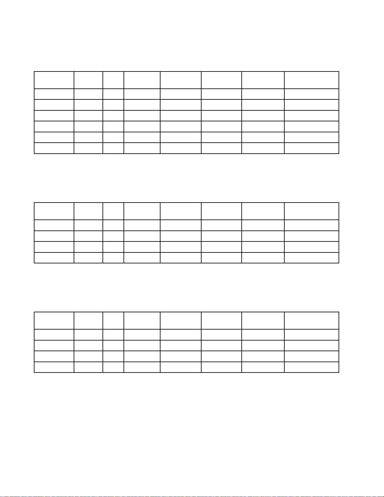
Models
HVLP
HVLP HVLP
EquippedwithHVLPaircap.
Part
Part Part
L40M77A40
L40T77A40
L60M77A60
L60T77A60
L85M77A85
L85T77A85
High
High High
EquippedwithESOn-OffwithAirRestrictorandFluidAdjustmentValve,whichlimitsairowtotheturbine.
Forapplicationsthatrequirehighairowattheaircap.
Part
Part Part
L60M57A60
Gun
Gun Gun
No.
No. No.
Air
Air Air
No.
No. No.
Models
Models Models
Series
Series Series
Flow
Flow Flow
Series
Series Series
kV
kV kV
Gun
Gun Gun
kV
kV kV
Display
Display Display
SmartStd1.5Std
StdStd1.5Std
SmartStd1.5Std
StdStd1.5Std
SmartStd1.5Std
StdStd1.5Std
Models
Models Models
Display
Display Display
SmartStd1.5StdStdStd
Electrode
Electrode Electrode
Electrode
Electrode Electrode
Nozzle
Nozzle Nozzle
(mm)
(mm) (mm)
Nozzle
Nozzle Nozzle
(mm)
(mm) (mm)
Air
Cap
Air Air
Cap Cap
HVLP
HVLP
HVLP
HVLP
HVLP
HVLP
Air
Cap
Air Air
Cap Cap
Fluid
Tube
Fluid Fluid
Tube Tube
Std
Std
Std
Std
Std
Std
Fluid
Tube
Fluid Fluid
Tube Tube
L60T57A60
L85M57A85
L85T57A85
Fixed
Fixed Fixed
EquippedwithESOn-OffandFixedFluidValve,whichextendselectrodeandnozzlelife.Forapplicationswith
abrasive,metallic,andextremelyabrasivematerials.
Part
Part Part
L60T98A60
L60T99A60
L85T90A85
L85T96A85
Fluid
Fluid Fluid
No.
No. No.
Flow
Flow Flow
Series
Series Series
Gun
Gun Gun
kV
kV kV
StdStd1.5StdStdStd
SmartStd1.5StdStdStd
StdStd1.5StdStdStd
Models
Models Models
Display
Display Display
StdShort
StdShort
Std
Std
Electrode
Electrode Electrode
HW1.5PHW
HW1.5PHW
Nozzle
Nozzle Nozzle
(mm)
(mm) (mm)
1.5PHW
1.5PHW
Air
Cap
Air Air
Cap Cap
StdStd
StdHC
StdStd
StdHC
Fluid
Tube
Fluid Fluid
Tube Tube
63A2494P
Page 7
Approvals
2575
Approvals
Approvals Approvals
G
II IIII2 22G G
0.24mJT6
FM12ATEX0068
EN50050-1
Ta0°C–50°C
Related
Related Related
Manual
Manual Manual
3A2498
3A6929
3A7005
3A6833
307263ProbeandMeter,Instructions
308393
309227
309455TestFixture,HighVoltageProbe,andkVMeter,Instructions
406999
No.
No. No.
Manuals
Manuals Manuals
Description
Description Description
RoundSprayKit,Instructions(largepattern)
RoundSprayKit,Instructions(smallandmediumpattern)
QuickAdjustFanValveKit,Instructions
HVLPVericationKit,Instructions
GunWasherKit,Instructions
GunFlushBoxModule,Instructions
VoltageTesterConversionKit,Instructions
3A2494P
7
Page 8
Warnings
Warnings
Warnings Warnings
Thefollowingwarningsareforthesetup,use,grounding,maintenance,andrepairofthisequipment.The
exclamationpointsymbolalertsyoutoageneralwarningandthehazardsymbolsrefertoprocedure-specic
risks.Whenthesesymbolsappearinthebodyofthismanualoronwarninglabels,referbacktothese
Warnings.Product-specichazardsymbolsandwarningsnotcoveredinthissectionmayappearthroughout
thebodyofthismanualwhereapplicable.
WARNING
WARNING WARNING
FIRE,
EXPLOSION,
FIRE, FIRE,
EXPLOSION, EXPLOSION,
Flammablefumes,suchassolventandpaintfumes,inworkareacanigniteorexplode.Paint
orsolventowingthroughtheequipmentcancausestaticsparking.Tohelppreventre,
explosion,andelectricshock:
•Electrostaticequipmentmustbeusedonlybytrained,qualiedpersonnelwhounderstand
therequirementsofthismanual.
•Groundallequipment,personnel,objectbeingsprayed,andconductiveobjectsinorcloseto
sprayarea.Resistancemustnotexceed1megohm.SeeGrounding Grounding
•OnlyusegroundedGracoconductiveairsupplyhoses.
•Donotusepaillinersunlesstheyareconductiveandgrounded.
Stop
•Stop Stop
•Checkgunresistance,hoseresistance,andelectricalgroundingdaily.
•Useandcleanequipmentonlyinwellventilatedarea.
•Interlockthegunairanduidsupplytopreventoperationunlessventilationairowisabove
•UseonlyGroupIIAorGroupDmaterials.
•Usecleaningsolventswithhighestpossibleashpointwhenushingorcleaningequipment.
•Neversprayorushsolventathighpressure.
•Tocleantheexterioroftheequipment,cleaningsolventsmusthaveaashpointatleast15°
•Alwaysturntheelectrostaticsoffwhenushing,cleaningorservicingequipment.
•Eliminateallignitionsourcessuchaspilotlights,cigarettes,portableelectriclamps,and
•Donotplugorunplugpowercordsorturnlightsonoroffwhenammablefumesarepresent.
•Keepworkareafreeofdebris,includingsolvent,ragsandgasoline.
•Keepthesprayareacleanatalltimes.Usenon-sparkingtoolstocleanresiduefromthe
•Keepaworkingreextinguisherintheworkarea.
operation
operation operation
equipmentuntilyouidentifyandcorrecttheproblem.
theminimumrequiredvalue.
Cor59°Faboveambienttemperature.Non-ignitableuidsarepreferred.
plasticdropcloths(potentialstaticsparking).
boothandhangers.
AND
ELECTRIC
AND AND
ELECTRIC ELECTRIC
immediately
immediately immediately
ifstaticsparkingoccursoryoufeelashock.Donotuse
SHOCK
SHOCK SHOCK
HAZARD
HAZARD HAZARD
Grounding
instructions.
83A2494P
Page 9
WARNING
WARNING WARNING
PRESSURIZED
PRESSURIZED PRESSURIZED
Fluidfromtheequipment,leaks,orrupturedcomponentscansplashintheeyesoronskin
andcauseseriousinjury.
EQUIPMENT
EQUIPMENT EQUIPMENT
HAZARD
HAZARD HAZARD
Warnings
•FollowthePressure Pressure
cleaning,checking,orservicingequipment.
•Tightenalluidconnectionsbeforeoperatingtheequipment.
•Checkhoses,tubes,andcouplingsdaily.Replacewornordamagedpartsimmediately.
EQUIPMENT
EQUIPMENT EQUIPMENT
Misusecancausedeathorseriousinjury.
•Donotoperatetheunitwhenfatiguedorundertheinuenceofdrugsoralcohol.
•Donotexceedthemaximumworkingpressureortemperatureratingofthelowestrated
systemcomponent.SeeTechnical Technical
•Useuidsandsolventsthatarecompatiblewithequipmentwettedparts.SeeTechnical Technical
Specications
Specications Specications
Forcompleteinformationaboutyourmaterial,requestaSafetyDataSheet(SDS)from
yourdistributororretailer.
•Donotleavetheworkareawhileequipmentisenergizedorunderpressure.
•TurnoffallequipmentandfollowthePressure Pressure
•Checkequipmentdaily.Repairorreplacewornordamagedpartsimmediatelywithgenuine
manufacturer’sreplacementpartsonly.
•Donotalterormodifyequipment.Alterationsormodicationsmayvoidagencyapprovals
andcreatesafetyhazards.
•Makesureallequipmentisratedandapprovedfortheenvironmentinwhichyouareusingit.
•Useequipmentonlyforitsintendedpurpose.Callyourdistributorforinformation.
•Routehosesandcablesawayfromtrafcareas,sharpedges,movingparts,andhotsurfaces.
•Donotkinkoroverbendhosesorusehosestopullequipment.
•Keepchildrenandanimalsawayfromworkarea.
•Complywithallapplicablesafetyregulations.
PLASTIC
PLASTIC PLASTIC
Manycleaningsolventscandegradeplasticpartsandcausethemtofail,whichcouldcause
seriousinjuryorpropertydamage.
Pressure
MISUSE
MISUSE MISUSE
PARTS
PARTS PARTS
Relief
Procedure
Relief Relief
Procedure Procedure
HAZARD
HAZARD HAZARD
Technical
inallequipmentmanuals.Readuidandsolventmanufacturer’swarnings.
CLEANING
CLEANING CLEANING
SOLVENT
SOLVENT SOLVENT
whenyoustopspraying/dispensingandbefore
Specications
Specications Specications
Pressure
HAZARD
HAZARD HAZARD
Relief
Relief Relief
inallequipmentmanuals.
Procedure
Procedure Procedure
whenequipmentisnotinuse.
Technical
•Useonlycompatiblesolventstocleanplasticstructuralorpressure-containingparts.
•SeeTechnical Technical
Technical
thesolventmanufacturerforinformationandrecommendationsaboutcompatibility.
Specications
Specications Specications
inallequipmentmanualsformaterialsofconstruction.Consult
3A2494P9
Page 10
Warnings
WARNING
WARNING WARNING
TOXIC
TOXIC TOXIC
Toxicuidsorfumescancauseseriousinjuryordeathifsplashedintheeyesoronskin,
inhaled,orswallowed.
•ReadSafetyDataSheet(SDS)toknowthespecichazardsoftheuidsyouareusing.
•Storehazardousuidinapprovedcontainers,anddisposeofitaccordingtoapplicable
PERSONAL
PERSONAL PERSONAL
Wearappropriateprotectiveequipmentwhenintheworkareatohelppreventseriousinjury,
includingeyeinjury,hearingloss,inhalationoftoxicfumes,andburns.Thisprotective
equipmentincludesbutisnotlimitedto:
•Protectiveeyewear,andhearingprotection.
•Respirators,protectiveclothing,andglovesasrecommendedbytheuidandsolvent
FLUID
FLUID FLUID
guidelines.
manufacturer.
OR
FUMES
OR OR
FUMES FUMES
PROTECTIVE
PROTECTIVE PROTECTIVE
HAZARD
HAZARD HAZARD
EQUIPMENT
EQUIPMENT EQUIPMENT
103A2494P
Page 11

GunOverview
Gun
Gun Gun
How
How How
Theairhosesuppliesairtothespraygun.Partof
theairoperatesthealternatorturbineandtherest
oftheairatomizestheuidbeingsprayed.The
alternatorgeneratespower,whichisconvertedby
thepowercartridgetosupplyhighvoltagetothe
gun’selectrode.
Overview
Overview Overview
the
Electrostatic
the the
Electrostatic Electrostatic
Spray
Spray Spray
Gun
Gun Gun
Works
Works Works
Thepumpsuppliesuidtotheuidhoseandgun,
wheretheuidiselectrostaticallychargedasit
passestheelectrode.Thechargeduidisattracted
tothegroundedworkpiece,wrappingaroundand
evenlycoatingallsurfaces.
3A2494P
11
Page 12
GunOverview
Controls,
Controls, Controls,
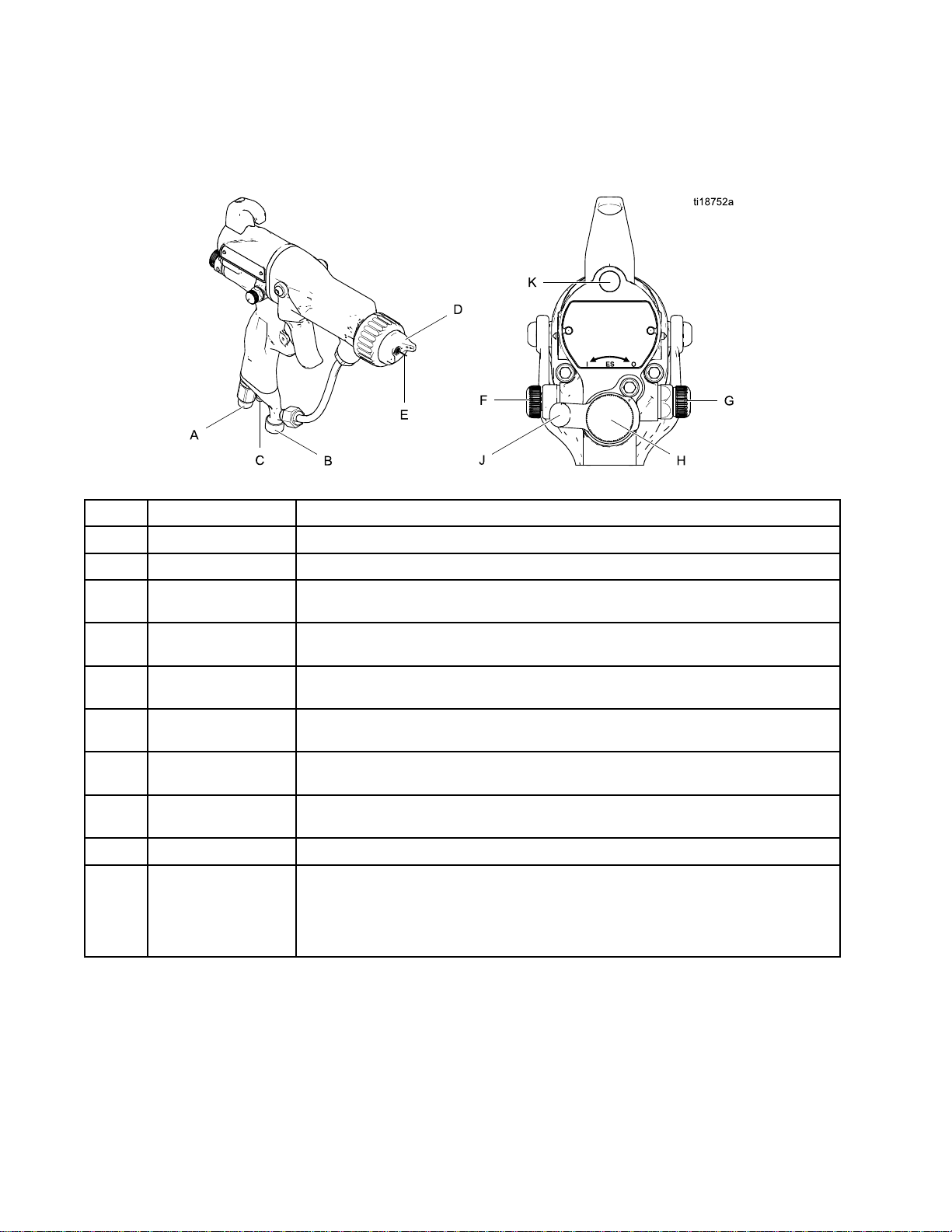
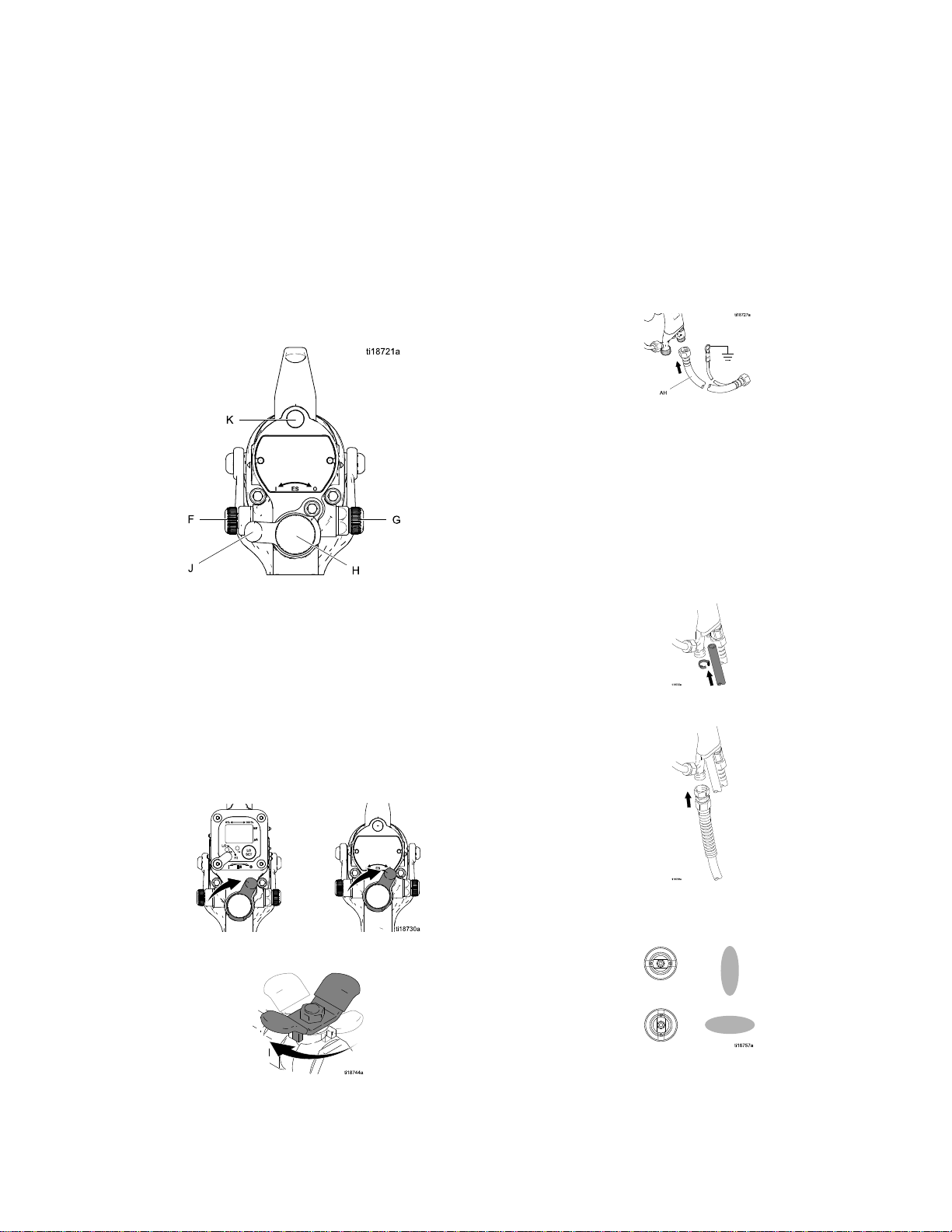
Theelectrostaticgunincludesthefollowingcontrols,indicators,andcomponents(seeFig.1).Forinformation
onSmartguns,seeSmartGuns,page13.
Figure1GunOverview
Item
Item Item
A
BFluidInlet
Indicators,
Indicators, Indicators,
Description
Description Description
AirSwivelInlet1/4npsm(m)left-handthread,forGracogroundedairsupplyhose.
and
Components
and and
Components Components
Purpose
Purpose Purpose
3/8npsm(m),foruidsupplyhose.
C
D
EElectrodeNeedle
FFanAirAdjustment
G
HFluidAdjustment
J
K
TurbineAir
Exhaust
AirCapandNozzleShapesthespraypattern.SeeAirCaps,page82and
Valve
AtomizingAir
RestrictorValve
Knob
ESOn-OffValveTurnselectrostaticsON(I)orOFF(O).
ESIndicator(standardgunonly;for
Smartgunindicator,seeOperating
Mode,page13)
Barbedtting,forsuppliedexhausttube.
FluidNozzles,page79foravailablesizes.
Supplieselectrostaticchargetotheuid.See
ElectrodeSelectionChart,page88.
Adjustsfansizeandshape.Canbeusedtodecreasepatternlength.
Restrictsaircapairow.Replacewithplug(included)ifdesired.
Adjustsuidowbylimitinguidneedletravel.Useonlyinlowow
conditions,toreducewear.
LitwhenESisON(I).Colorindicatesalternatorfrequency.SeetheLED
indicatortableintheGunSetupProcedure,page25.
12
3A2494P
Page 13
GunOverview
Smart
Smart Smart
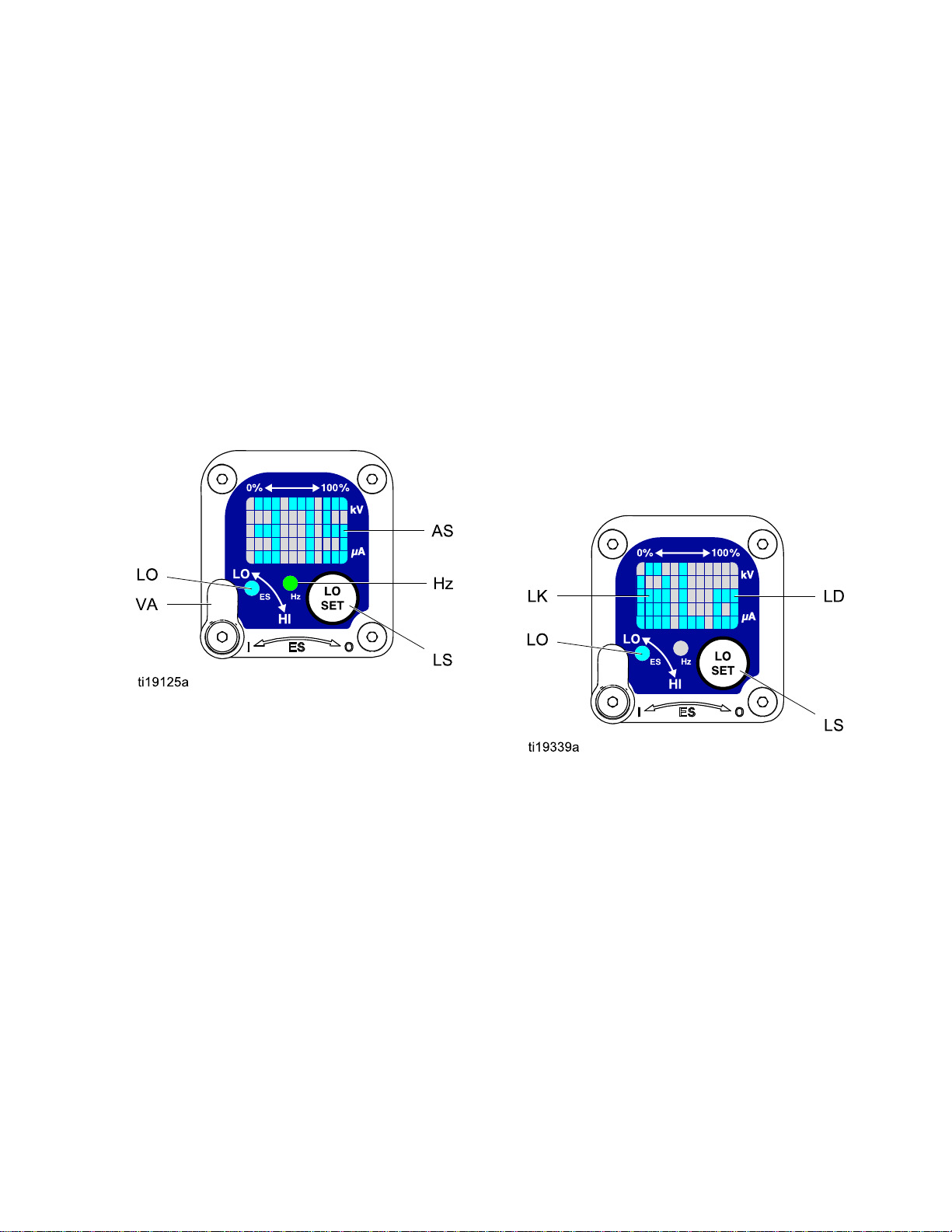
TheSmartGunmoduledisplayssprayingvoltage,
current,alternatorspeed,andthevoltagesetting(low
orhigh).Italsoallowstheusertochangetoalower
sprayingvoltage.Themodulehastwomodes:
•OperatingMode
•DiagnosticMode
Operating
Operating Operating
Bar
Bar Bar
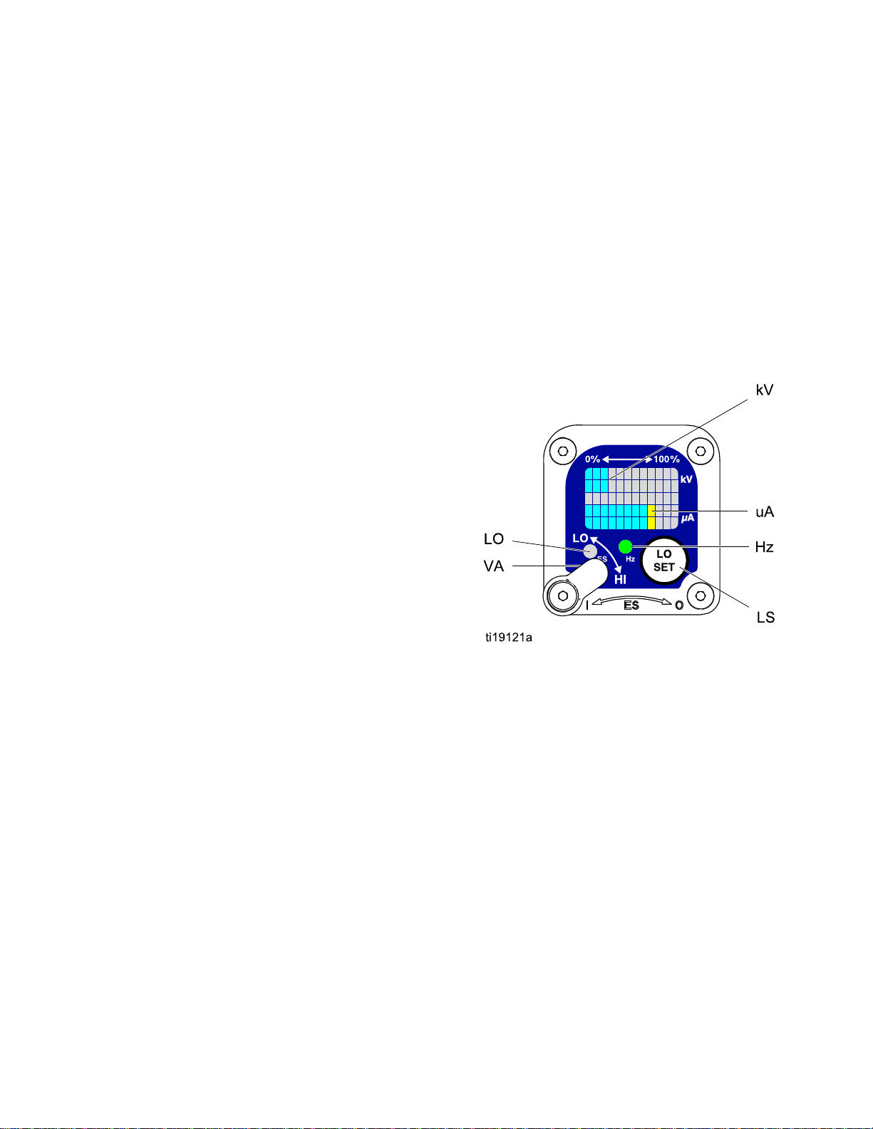
SeeFig.2andSmartGunKey,page15.The
OperatingModedisplaysgundataduringnormal
spraying.Thedisplayusesabargraphtoshowthe
voltagelevelinkiloVolts(kV)andthecurrentlevelin
microAmperes(uA).Thebargraphrangeisfrom0
to100%foreachvalue.
IfthebargraphLEDsareblue,thegunisreadyto
spray.IftheLEDsareyelloworred,thecurrentis
toohigh.Theuidmaybetooconductive,orsee
ElectricalTroubleshooting,page46forotherpossible
causes.
Guns
Guns Guns
Mode
Mode Mode
Graph
Graph Graph
Voltage
Voltage Voltage
Thevoltageadjustmentswitch(VA)allowsthe
operatortochangefromlowtohighvoltage.
•Thehighvoltagesettingisdeterminedbythe
maximumvoltageofthegunandisnotadjustable.
•Thelowvoltageindicator(LO)lights
whentheswitchissettoLO.Thelow
voltagesettingisuseradjustable.See
AdjustingtheLowVoltageSetting,page14.
NOTE:
NOTE: NOTE:
haslostcommunicationwiththepowersupply.See
ErrorDisplay,page14,forfurtherinformation.
Adjustment
Adjustment Adjustment
IftheErrordisplayappears,theSmartmodule
Switch
Switch Switch
Hz
Indicator
Hz Hz
Indicator Indicator
TheHzindicatorfunctionsthesameastheES
indicatoronstandardguns.Theindicatorlightsto
showthealternatorspeedstatus,andhasthree
colors:
•Greenindicatesthealternatorspeediscorrect.
•Iftheindicatorchangestoamberafteronesecond,
increasetheairpressure.
•Iftheindicatorchangestoredafteronesecond,
theairpressureistoohigh.Decreaseairpressure
untiltheindicatorisgreen.Tomaintainahigher
airpressure,installESOn/OffValveRestrictorKit
26A160.Then,adjustthepressureasneededto
ensuretheindicatorremainsgreen.
Figure2SmartGunModuleinOperatingMode
3A2494P13
Page 14
GunOverview
Error
Error Error
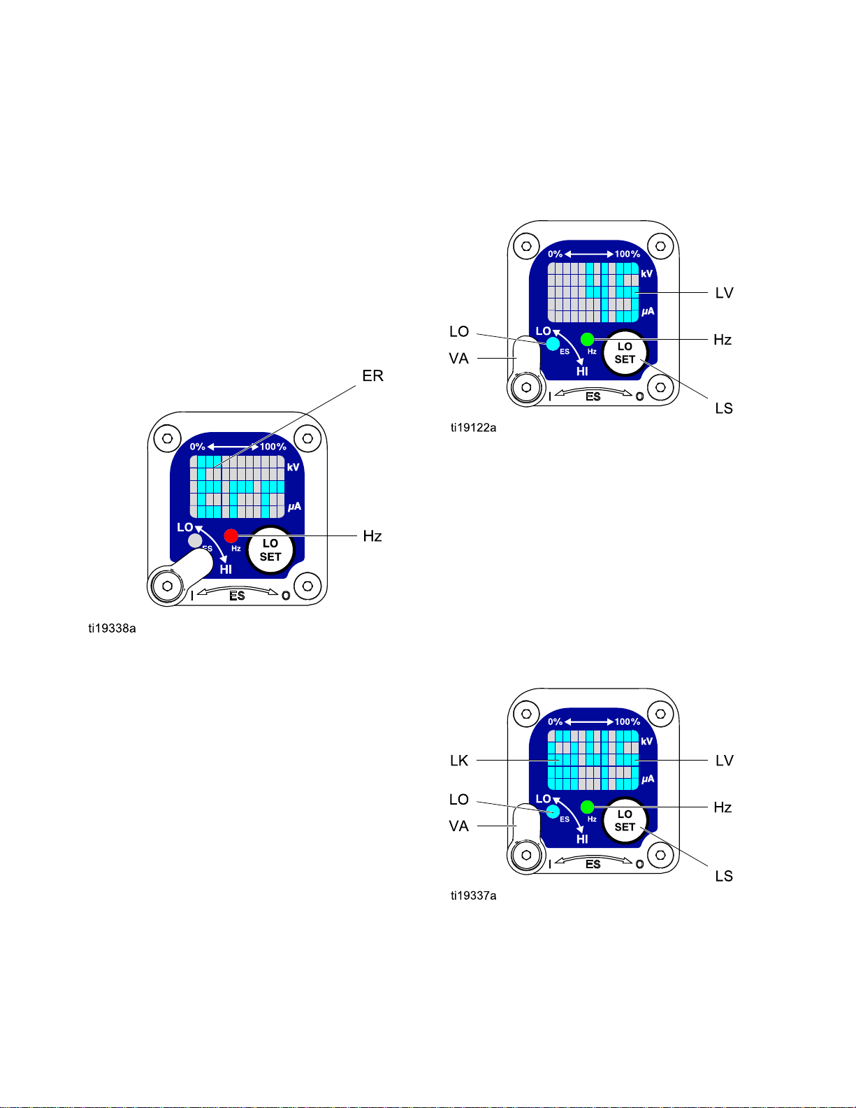
IftheSmartmodulelosescommunicationwith
thepowersupply,theErrordisplayappears,the
Hzindicatorturnsred,andtheSmartmoduleis
disabled.SeeFig.3andSmartGunKey,page15.
ThiscanoccurinOperatingModeorDiagnostic
Mode.SeeElectricalTroubleshooting,page46.
CommunicationmustberestoredtomaketheSmart
modulefunctional.
NOTE:
NOTE: NOTE:
appear.Ifthegunhasbeendisassembled,wait8
secondsbeforesprayingtoensurethatanError
conditionhasnotoccurred.
NOTE:
NOTE: NOTE:
displaywillnotappear.
Display
Display Display
Ittakes8secondsfortheErrordisplayto
Ifthereisnopowertothegun,theError
foryourgun.Continuepressingthebuttonuntilyou
reachthedesiredsetting.
NOTE:
NOTE: NOTE:
returntotheOperatingScreen.
NOTE:
NOTE: NOTE:
LockSymbol,page14.
Figure4LowVoltageSettingScreen(Unlocked)
Lock
Lock Lock
After2secondsofinactivitythedisplaywill
Thelowvoltagesettingmaybelocked.See
Symbol
Symbol Symbol
Figure3ErrorDisplay
Adjusting
Adjusting Adjusting
Thelowvoltagesettingisuseradjustable.Toaccess
thelowvoltagesettingscreenwheninOperating
Mode,presstheLOSETbutton(LS)momentarily.
Thescreenwilldisplaythecurrentlowvoltage
setting.SeeFig.4andSmartGunKey,page15.
Thepossiblerangesare:
•85kVguns:40–85kV
•60kVguns:30–60kV
•40kVguns:20–40kV
SettheVoltageAdjustmentswitch(VA)toLO.Press
theLOSETbuttonrepeatedlytoincreasethesetting
inincrementsof5.Whenthedisplayreachesthe
maximumsettingitwillreturntotheminimumsetting
the
Low
the the
Voltage
Low Low
Voltage Voltage
Setting
Setting Setting
Thelowvoltagesettingmaybelocked.Whenlocked,
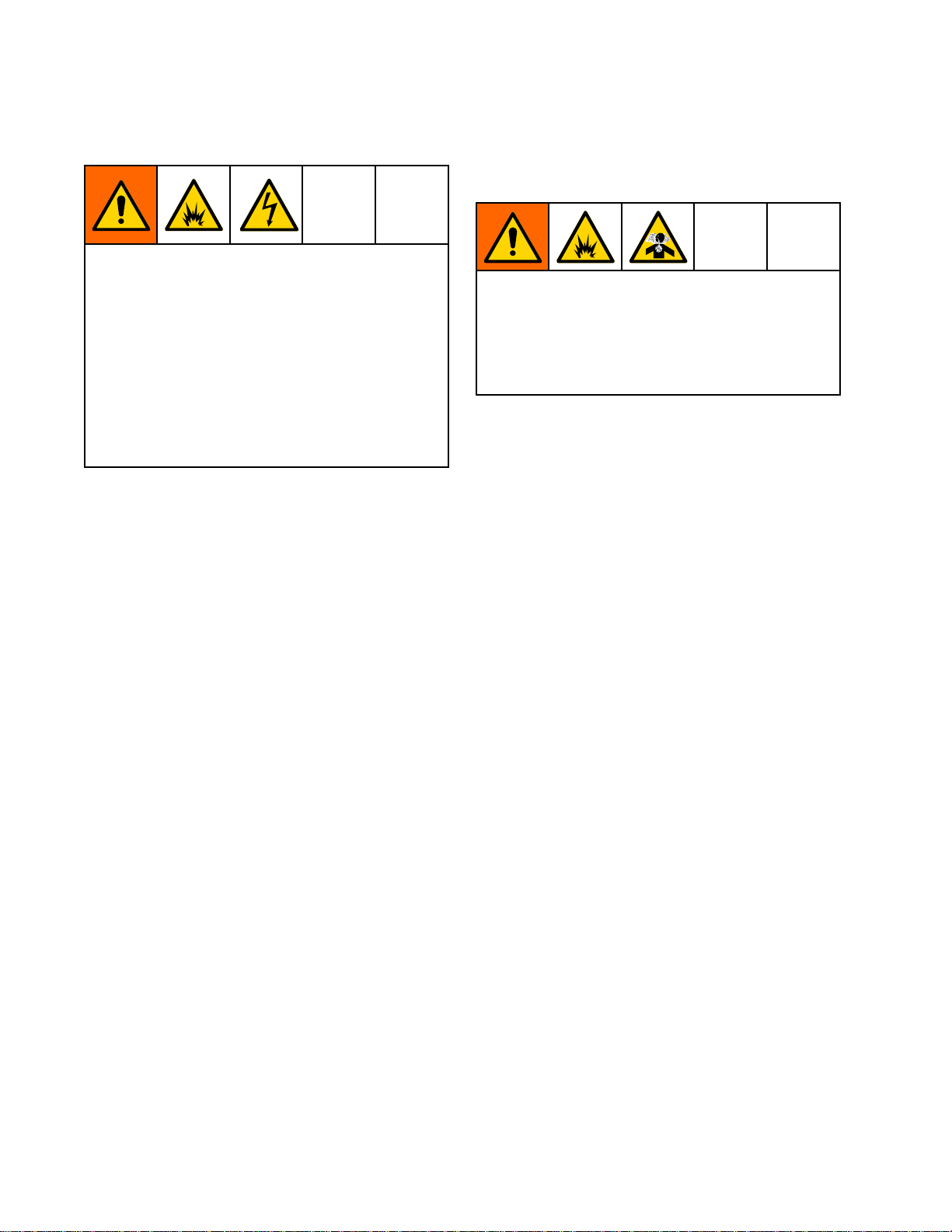
animage(LK)appearsonthescreen.SeeFig.5
andSmartGunKey,page15.
•WheninHImode,thelowvoltagesettingisalways always
locked.ThelocksymbolwillappearwhentheLO
SETbuttonispressed.
•WheninLOmode,thelocksymbolwill
only
only only
appearifthelockisenabled.See
LowVoltageLockScreen,page17,tolockor
unlockthelowvoltagesetting.
Figure5LowVoltageSettingScreen(Locked)
always
14
3A2494P
Page 15

GunOverview
Smart
Smart Smart
Table
Table Table
Item
Item Item
VA
LO
kV
uA
LSLOSETbuttonPressmomentarilytoentertheLowVoltageSettingscreen.
Gun
Key
Gun Gun
Key Key
Key
for
Figs.
1 11Key Key
for for
Description
Description Description
VoltageAdjustmentSwitchTwo-positionswitchsetsSmartgunvoltagetolowsetting(LO)or
LowVoltageMode
Indicator
Voltage(kV)DisplayDisplaysactualsprayingvoltageofthegun,inkV.InOperatingMode,
Current(uA)DisplayDisplaysactualsprayingcurrentofthegun,inuA.InOperatingMode,
2–9.
Figs. Figs.
2–9. 2–9.
Purpose
Purpose Purpose
highsetting(HI).ThisswitchisfunctionalinOperatingModeandin
DiagnosticMode.
Lights(blue)whentheSmartgunissettoLowVoltage.
displayisabargraph.InDiagnosticMode,voltageisdisplayedas
anumber.
displayisabargraph.InDiagnosticMode,currentisdisplayedas
anumber.
Pressandholdforapproximately5secondstoenterorexitDiagnostic
Mode.
WhileinDiagnosticMode,pressmomentarilytoadvancethrough
screens.
WhileontheLowVoltageLockScreen(inDiagnosticMode),press
andholdtoturnthelockonoroff.
LVLowVoltageDisplayDisplaysthelowvoltagesettingasanumber.Thesettingcanbe
changed.SeeFig.4.
LKLowVoltageLocked
LD
ERErrorDisplay
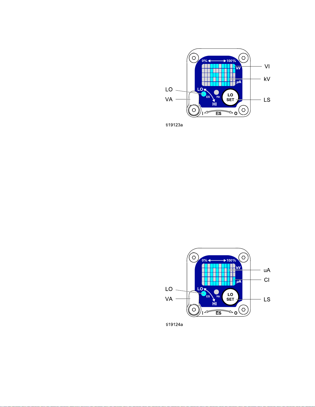
VIVoltageIndicator
CICurrentIndicatorInDiagnosticMode,thetwobottomrightLEDsofthescreenlight,
ASAlternatorSpeedDisplayInDiagnosticMode,Hzlevelisdisplayedasanumber.SeeFig.8.
Hz
LODisplayAppearsontheLowVoltageLockScreen.SeeFig.9.
AlternatorSpeedIndicatorInOperatingMode,indicatorcolorvariestoshowthealternatorspeed
Appearsifthelowvoltagesettingislocked.SeeFig.5andFig.9.
AppearsiftheSmartmodulelosescommunicationwiththepower
supply.SeeFig.3.
InDiagnosticMode,thetwotoprightLEDsofthescreenlight,
indicatingthatthevaluedisplayedisinkV.SeeFig.6.
indicatingthatthevaluedisplayedisinuA.SeeFig.7.
status:
•Greenindicatesthealternatorspeedisatthecorrectlevel.
•Iftheindicatorchangestoamberafteronesecond,thealternator
speedistoolow.
•Iftheindicatorchangestoredafteronesecond,thealternatorspeed
istoohigh.TheindicatoralsoturnsrediftheErrordisplayappears.
InDiagnosticMode,theindicatorisgreenwhenintheAlternator
Speed(Hertz)screen.
3A2494P15
Page 16
GunOverview
Diagnostic
Diagnostic Diagnostic
DiagnosticModeincludesfourscreenswhichdisplay
gundata:
•Voltage(kiloVolts)Screen
•Current(microAmperes)Screen
•AlternatorSpeed(Hertz)Screen
•LowVoltageLockScreen
NOTE:
NOTE: NOTE:
lowvoltagesetting;thesettingisnotadjustablein
DiagnosticMode.However,thevoltageadjustment
switch(VA)canbesettoHIorLOinOperatingMode
andinDiagnosticMode.
ToenterDiagnosticMode,pressandholdtheLOSET
(LS)buttonforapproximately5seconds.Thedisplay
willgototheVoltage(kiloVolts)Screen,page16.
Toadvancetothenextscreen,presstheLOSET
buttonagain.
ToexitDiagnosticMode,pressandholdtheLOSET
buttonforapproximately5seconds.Thescreenwill
returntoOperatingMode.
NOTE:
NOTE: NOTE:
Mode,thelastscreenviewedwillbedisplayedwhen
thegunisretriggered.
NOTE:
NOTE: NOTE:
fromtheLowVoltageLockScreen.See
LowVoltageLockScreen,page17fordetails.
Mode
Mode Mode
YoumustbeinOperatingModetoadjustthe
IfthegunisdetriggeredwhileinDiagnostic
DiagnosticModecannotbeexited
Figure6Voltage(kiloVolts)Screen
Current
Current Current
TheCurrent(microAmperes)Screenisthesecond
screenintheDiagnosticMode.SeeFig.7and
SmartGunKey,page15.Toenterthisscreen,press
theLOSETbuttonwhileintheVoltage(kiloVolts)
Screen.
Thisscreendisplaysthesprayingcurrentofthegun
asanumber(uA),roundedtothenearest5uA.The
twobottomrightLEDs(CI)ofthedisplaypanellight,
indicatingthattheCurrent(microAmperes)Screen
isdisplayed.Thedisplayisareadoutandcannot
bechanged.
(microAmperes)
(microAmperes) (microAmperes)
Screen
Screen Screen
Voltage
Voltage Voltage
TheVoltage(kiloVolts)Screenistherstscreento
appearafterenteringDiagnosticMode.SeeFig.6
andSmartGunKey,page15.Toenterthisscreen,
pressandholdtheLOSETbuttonforapproximately
5secondswhileintheOperatingMode.
Thisscreendisplaysthesprayingvoltageofthe
gunasanumber(kV),roundedtothenearest5kV.
ThetwotoprightLEDs(VI)ofthedisplaypanel
light,indicatingthattheVoltage(kiloVolts)Screen
isdisplayed.Thedisplayisareadoutandcannot
bechanged.
PresstheLOSETbuttontoadvancetothe
Current(microAmperes)Screen,page16.Press
andholdforapproximately5secondstoreturnto
OperatingMode.
(kiloVolts)
(kiloVolts) (kiloVolts)
Screen
Screen Screen
PresstheLOSETbuttontoadvancetothe
AlternatorSpeed(Hertz)Screen,page17.Press
andholdforapproximately5secondstoreturnto
OperatingMode.
Figure7Current(microAmperes)Screen
163A2494P
Page 17
GunOverview
Alternator
Alternator Alternator
TheAlternatorSpeed(Hertz)Screenisthethird
screenintheDiagnosticMode.SeeFig.8and
SmartGunKey,page15.Toenterthisscreen,
presstheLOSETbuttonwhileintheCurrent
(microAmperes)Screen.
Thisscreendisplaysthealternatorspeedasa3digit
number(AS),roundedtothenearest10Hz.The
displayisareadoutandcannotbechanged.Ifthe
alternatorspeedisgreaterthan999Hz,thedisplay
willshow999.
TheHzindicatorlightsgreentoshowthatyouare
viewingtheAlternatorSpeed(Hertz)Screen.
PresstheLOSETbuttontoadvancetothe
LowVoltageLockScreen,page17.Pressandhold
forapproximately5secondstoreturntoOperating
Mode.
Speed
Speed Speed
(Hertz)
(Hertz) (Hertz)
Screen
Screen Screen
Low
Voltage
Low Low
Voltage Voltage
TheLowVoltageLockScreenisthefourth
screenintheDiagnosticMode.SeeFig.9and
SmartGunKey,page15.Toenterthisscreen,press
theLOSETbuttonwhileintheAlternatorSpeed
(Hertz)Screen.
ThisscreendisplaysthestatusoftheLowVoltage
Lock.Ifthesettingislocked,thelockimage(LK)
appearstotheleftoftheLodisplay(LD).Ifthesetting
isunlocked,thelockimagedoesnotappear.
Tochangethelockstatus,pressandholdthe
LOSETbuttonuntilthelockimageappearsor
disappears.Ifthelockisset,theimagewillalso
appearontheLowVoltageSettingScreenwhenin
lowvoltagemode(seeFig.4).
NOTE:
NOTE: NOTE:
screen,becausepressingandholdingtheLOSET
buttonisusedtoturnthelockonoroff.Toexit,
pressLOSETmomentarilytoreturntotheVoltage
(kiloVolts)Screen,thenexitDiagnosticModefrom
there.
DiagnosticModecannotbeexitedfromthis
Lock
Screen
Lock Lock
Screen Screen
Figure8AlternatorSpeed(Hertz)Screen
Figure9LowVoltageLockScreen
3A2494P
17
Page 18
Installation
Installation
Installation Installation
Installingandservicingthisequipmentrequires
accesstopartswhichmaycauseelectricshock
orotherseriousinjuryifworkisnotperformed
properly.
•Donotinstallorservicethisequipmentunless
youaretrainedandqualied.
•Besureyourinstallationcomplieswithlocal,
state,andnationalcodesfortheinstallation
ofelectricalapparatusinaClassI,Div.I,
hazardouslocationoraGroupII,ZoneI
explosiveatmospherelocation.
•Complywithalllocalcodesandregulations.
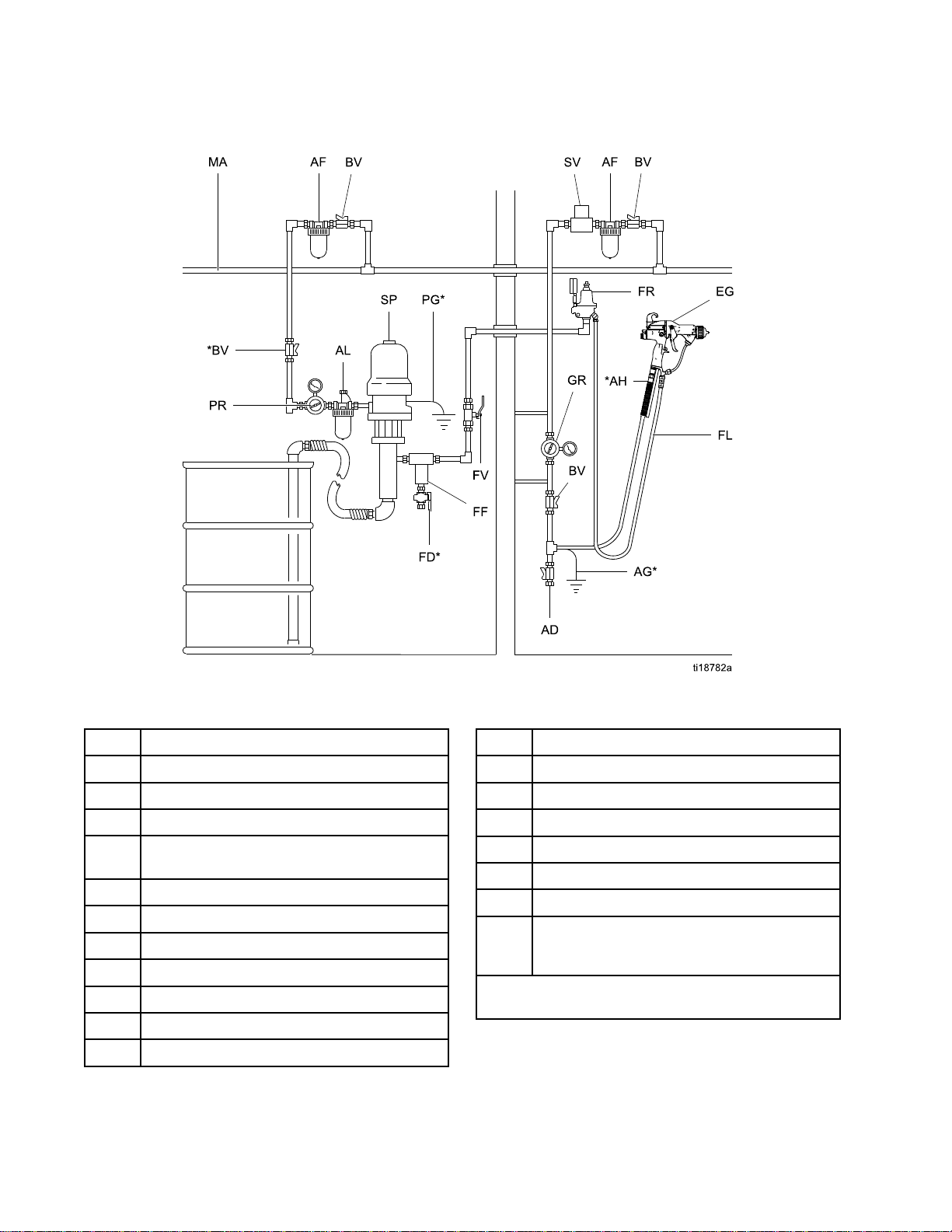
Fig.10(TypicalInstallation)showsatypical
electrostaticairspraysystem.Itisnotanactual
systemdesign.Forassistanceindesigningasystem
tosuityourparticularneeds,contactyourGraco
distributor.
Warning
Warning Warning
Sign
Sign Sign
Ventilate
Ventilate Ventilate
Donotoperatethegununlessventilatingairowis
abovetheminimumrequiredvalue.Providefresh
airventilationtoavoidthebuildupofammableor
toxicvaporswhenspraying,ushing,orcleaning
thegun.Interlockthegunairanduidsupply
topreventoperationunlessventilatingairowis
abovetheminimumrequiredvalue.
Thesprayboothmusthaveaventilationsystem.
Electricallyinterlockthegunairanduidsupplywith
theventilatorstopreventgunoperationanytimethat
theventilationairowfallsbelowminimumvalues.
Checkandfollowalllocalcodesandregulations
regardingairexhaustvelocityrequirements.Verify
theoperationoftheinterlockatleastonceayear.
NOTE:Theminimumallowableairexhaust
velocityis60feet/minute(19linearmeters/minute).
High-velocityairexhaustwilldecreasetheoperating
efciencyoftheelectrostaticsystem.
the
Spray
the the
Spray Spray
Booth
Booth Booth
Mountwarningsignsinthesprayareawherethey
caneasilybeseenandreadbyalloperators.An
EnglishWarningSignisprovidedwiththegun.
183A2494P
Page 19
Air
Supply
Air Air
Supply Supply
Toreducetheriskofelectricshock,theairsupply
hosemustbeelectricallyconnectedtoatrueearth
ground.Use Use
Hose.
Hose. Hose.
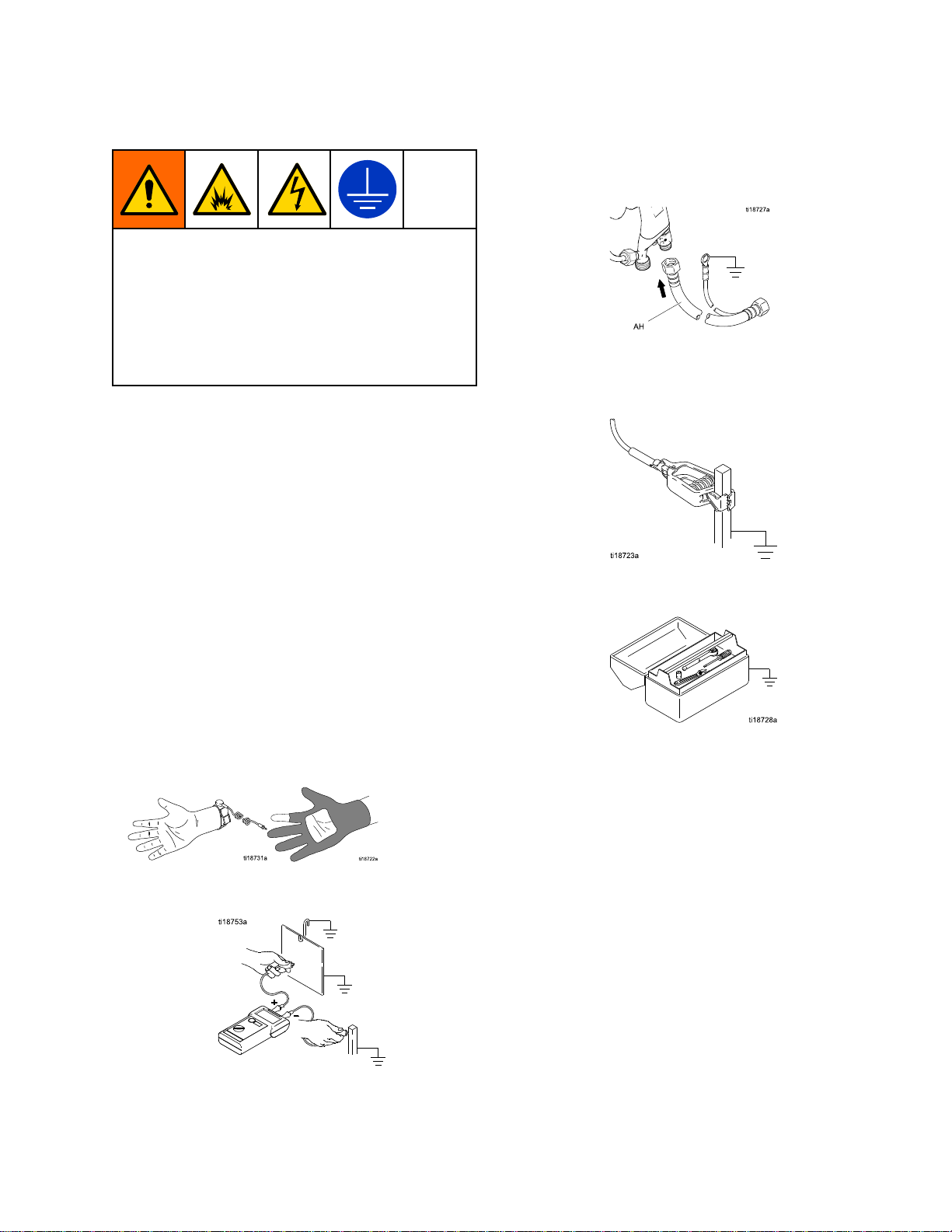
1.SeeFig.10.UsetheGracoGroundedAirSupply
Hose(AH)tosupplyairtothegun.Thegunair
inletttinghasaleft-handthread.Theairsupply
hosegroundwire(AG)mustbeconnectedtoa
trueearthground.Donotconnecttheairsupply
hosetothegunairinletyet.
2.Installanairlinelter/waterseparator(AF)onthe
gunairlinetoensureadry,cleanairsupplytothe
gun.Dirtandmoisturecanruintheappearance
ofyournishedworkpieceandcancausethe
guntomalfunction.
3.Installbleed-typeairregulators(PR,GR)on
thepumpandgunairsupplylinestocontrolair
pressuretothepumpandgun.
Line
Line Line
Use
only
Graco
only only
Graco Graco
Grounded
Grounded Grounded
Air
Supply
Air Air
Supply Supply
Installation
Fluid
Fluid Fluid
1.Blowouttheuidline(FL)withairandushit
2.Installauidregulator(FR)ontheuidlineto
3.Installauidlter(FF)nearthepumpoutlet,to
4.Theuiddrainvalve(FD)isrequiredinyour
Supply
Supply Supply
withsolvent.Usesolventwhichiscompatible
withtheuidtobesprayed.Donotconnectthe
uidsupplylinetothegunuidinletyet.
controluidpressuretothegun.
removeparticlesandsedimentwhichcouldclog
thespraynozzle.
Toreducetheriskofseriousinjury,including
splashinguidintheeyesorontheskin,do
notoperateequipmentwithouttheuiddrain
valve(FD)installed.
systemtoassistinrelievinguidpressureinthe
displacementpump,hose,andgun.Triggering
theguntorelievepressuremaynotbesufcient.
Installadrainvalveclosetothepump'suid
outlet.
Line
Line Line
Trappedaircancausethepumptocycle
unexpectedly,whichcanresultinserious
injury,includingsplashinguidintheeyesor
ontheskin.Donotoperatetheequipment
withoutthebleed-typeairvalve(BV)installed.
4.Installableed-typeairvalve(BV)onthepump
airsupplyline.Thebleed-typeairvalve(BV)is
requiredinyoursystemtoshutoffairtothepump
andrelieveairtrappedbetweenthevalveand
thepumpaftertheairregulatorisshutoff.Install
anadditionalbleed-typeairvalveonthemainair
line(MA)toisolatetheaccessoriesforservicing.
5.Installanairbleedvalve(BV)oneachgunair
supplylinetoshutoffairtothegun(s)andrelieve
airtrappedbetweenthevalveandthegunafter
theairregulatorisshutoff.
3A2494P19
Page 20
Installation
NON
HAZARDOUS
NON NON
- --HAZARDOUS HAZARDOUS
LOCATION
LOCATION LOCATION
HAZARDOUS
HAZARDOUS HAZARDOUS
LOCATION
LOCATION LOCATION
Figure10TypicalInstallation
Typical
Typical Typical
Item
Item Item
ADAirLineDrainValve
AF
AG*GunAirHoseGroundWire
AH*GracoGroundedAirHose(left-hand
ALPumpAirLineLubricator
BV*PumpBleed-TypeAirShutoffValve
EGElectrostaticAirSprayGun
FD*
FFFluidFilter
FL
FRFluidPressureRegulator
Installation
Installation Installation
Description
Description Description
AirFilter/WaterSeparator
threads)
FluidDrainValve
FluidSupplyLine
Key
Key Key
Item
Item Item
FV
GRGunAirPressureRegulator
MA
PG*PumpGroundWire
PRPumpAirPressureRegulator
SPSupplyPump
SV*VentilationFanInterlockSolenoidValve.
*Theseitemsarerequiredforsafeoperation.They
mustbepurchasedseparately.
Description
Description Description
FluidShutoffValve
MainAirSupplyLine
NOTE:
NOTE: NOTE:
asaGracoaccessory.
Thesolenoidvalveisnotoffered
203A2494P
Page 21
Installation
Grounding
Grounding Grounding
Theequipmentmustbegroundedtoreducethe
riskofstaticsparkingandelectricshock.Electric
orstaticsparkingcancausefumestoigniteor
explode.Impropergroundingcancauseelectric
shock.Groundallequipment,personnel,objects
beingsprayed,andconductiveobjectsinorclose
tothesprayarea.Theresistancemustnotexceed
1megohm.Groundingprovidesanescapewire
fortheelectriccurrent.
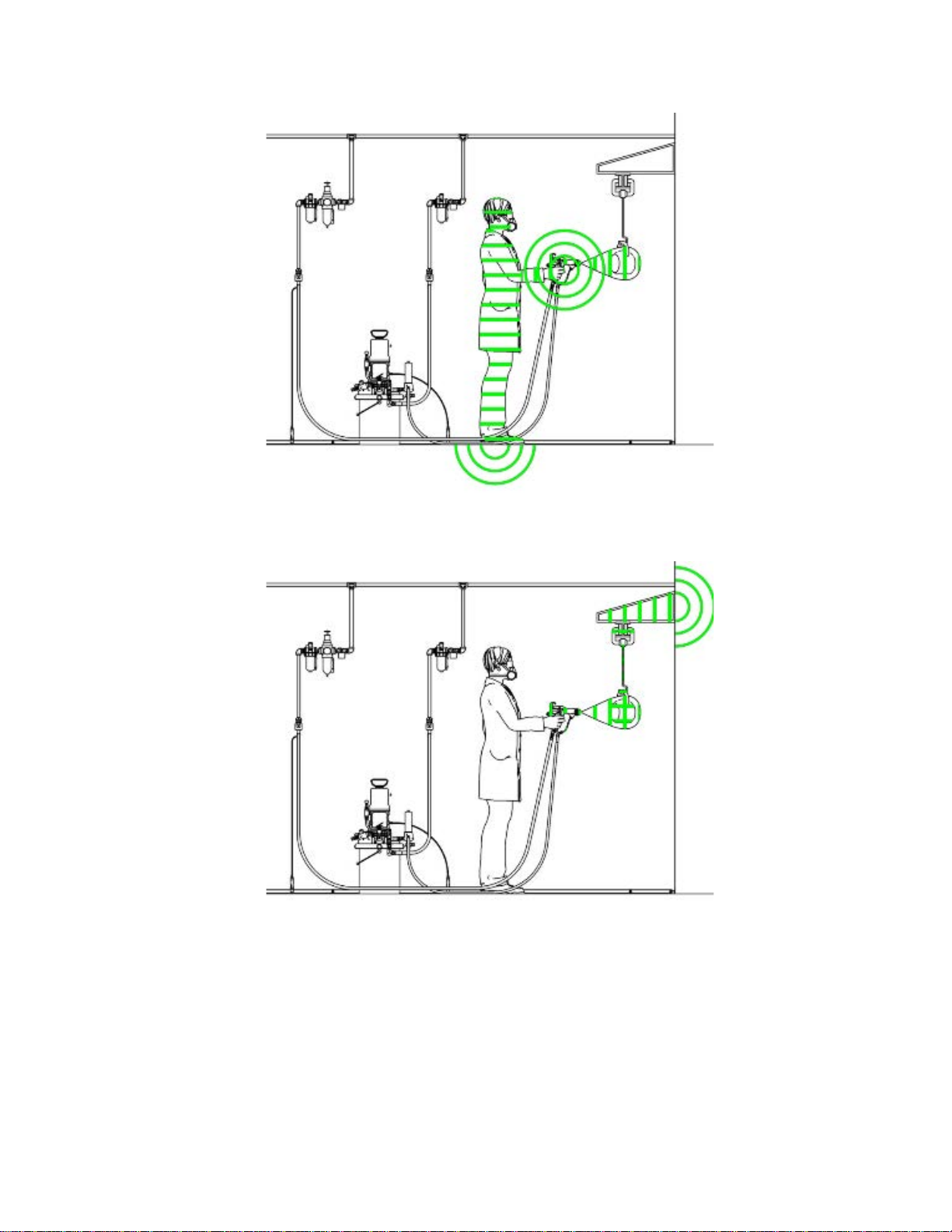
Whenoperatingtheelectrostaticgun,any
ungroundedobjects(suchaspeople,containers,and
tools)inthespraylocationcanbecomeelectrically
charged.
Thefollowingareminimumgroundingrequirements
forabasicelectrostaticsystem.Yoursystemmay
includeotherequipmentorobjectswhichmustbe
grounded.Yoursystemmustbeconnectedtoa
trueearthground.Checkgroundconnectionsdaily.
Checkyourlocalelectricalcodesandregulationsfor
detailedgroundinginstructions.
Allpersonsenteringthesprayarea
•
shoeshavingconductivesolessuchasleather,
orwearpersonalgroundingstraps.Donot
wearshoeswithnon-conductivesolessuchas
rubberorplastic.Ifglovesarenecessary,wear
theconductiveglovessuppliedwiththegun.If
non-Gracoglovesareworn,cutoffngersorpalm
areaofglovestoensureyourhandcontactsthe
groundedgunhandle.Conductiveglovesand
footwearmustnotexceed100megohmperEN
ISO20344,EN1149–5.
•
Objectbeingsprayed:
cleanandgroundedatalltimes.
Keeptheworkpiecehangers
mustwear
•
ElectrostaticAirSprayGun:
byconnectingtheGracoGroundedAirHose
(AH)tothegun,andconnectingtheairhose
groundwiretoatrueearthground.See
CheckGunElectricalGrounding,page34.
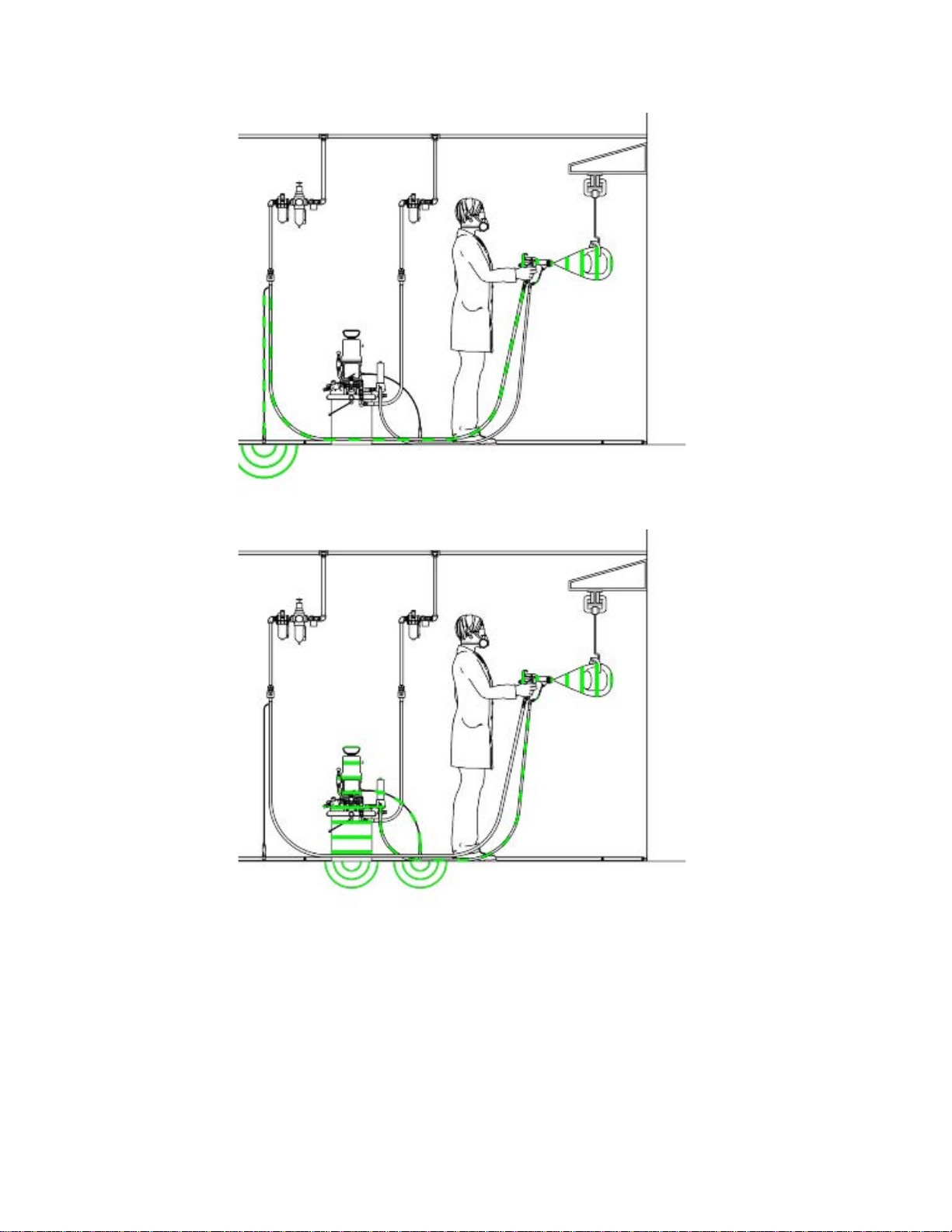
•
Pump/uidsource:
byconnectingitsgroundwiretoatrueearth
ground.
•
Allelectricallyconductiveobjectsordevicesinthe
sprayarea
•
Fluidandwastecontainers:
wastecontainersinthesprayarea.Donotusepail
linersunlesstheyareconductiveandgrounded.
Whenushingthespraygun,thecontainerused
tocatchtheexcessuidmustbeelectrically
conductiveandgrounded.
Aircompressors:
•
tothemanufacturer'srecommendations.
•
Allairanduidlines
Useonlygroundedhoseswithamaximumof100
feet(30.5m)combinedhoselengthtoensure
groundingcontinuity.
mustbeproperlygrounded.
Groundthepump/uidsource
Groundtheequipmentaccording
mustbeproperlygrounded.
Groundthegun
Groundalluidand
3A2494P
21
Page 22
Installation
•
Theoorofthesprayarea
conductiveandgrounded.Donotcovertheoor
withcardboardoranynon-conductivematerial
whichwouldinterruptgroundingcontinuity.
mustbeelectrically
•
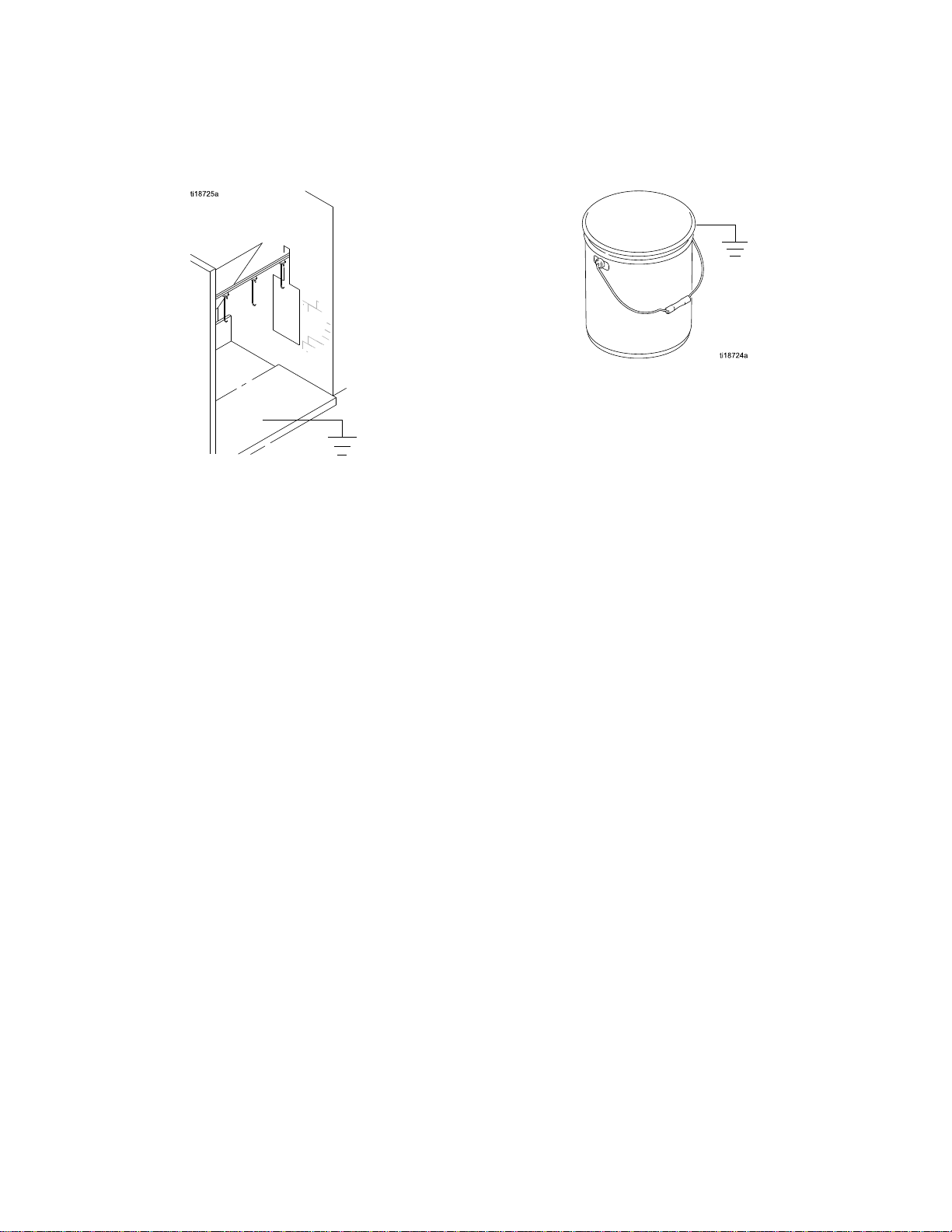
Flammableliquidsinthesprayarea
inapproved,groundedcontainers.Donotuse
plasticcontainers.Donotstoremorethanthe
quantityneededforoneshift.
•
Allsolventpails:
metalcontainers,whichareconductive.Donot
useplasticcontainers.Useonlynon-ammable
solvents.Donotstoremorethanthequantity
neededforoneshift.
Useonlyapproved,grounded
mustbekept
22
3A2494P
Page 23
Installation
Figure11GroundtheOperatorOperatorisgroundedthroughbareskincontactwith
thegunhandleandconductiveshoes.Aconductive
glovecanalsobeused.
Figure12GroundtheObjectBeingSprayedObjectbeingsprayedisgroundedthroughcontact
withthehangerandconveyorsystem.
3A2494P23
Page 24
Installation
Figure13GroundtheGunGunisgroundedthroughtheconductiveairhose.
Figure14GroundtheFluidSupplyFluidsupplylineandsourcemustbegrounded.
24
3A2494P
Page 25
GunSetup
Gun
Gun Gun
Gun
Gun Gun
Foradditionalstepstosetupspecialtyguns,
seeSoftSprayGunSetupProcedure,page28,
RoundSprayGunSetupProcedure,page31,
HVLPGunSetupProcedure,page29,and
AbrasiveMaterialGunSetupProcedure,page33.
Seethegurebelowtolocatetheelectrostaticgun
controls.
Figure15ElectrostaticGunControls
Setup
Setup Setup
Setup
Setup Setup
Procedure
Procedure Procedure
4.Checkgunresistance.Followthestepsin
TestGunResistance,page42.
5.ConnecttheGracogroundedairhosetothegun
airinlet.Thegunairinletttinghasleft-hand
threads.
6.FollowallstepsinGrounding,page21.
7.Followallstepsin
CheckGunElectricalGrounding,page34.
Readingmustbelessthan1megohm.
8.Verifythatthematerialresistivitymeets
requirementsforelectrostaticspray.See
CheckFluidResistivity,page35.
9.Connecttheexhausttubeandsecurewiththe
clampprovided.
1.Thegunisshippedwiththeuidnozzleandair
capinstalled.Checkthattheretainingringis
tight.
NOTE:
NOTE: NOTE:
sizeuidnozzleoraircap,see
FluidNozzleSelectionChart,page79and
AirCapSelectionGuide,page82.
Toinstallthenozzleandaircap,see
AirCapandNozzleReplacement,page48.
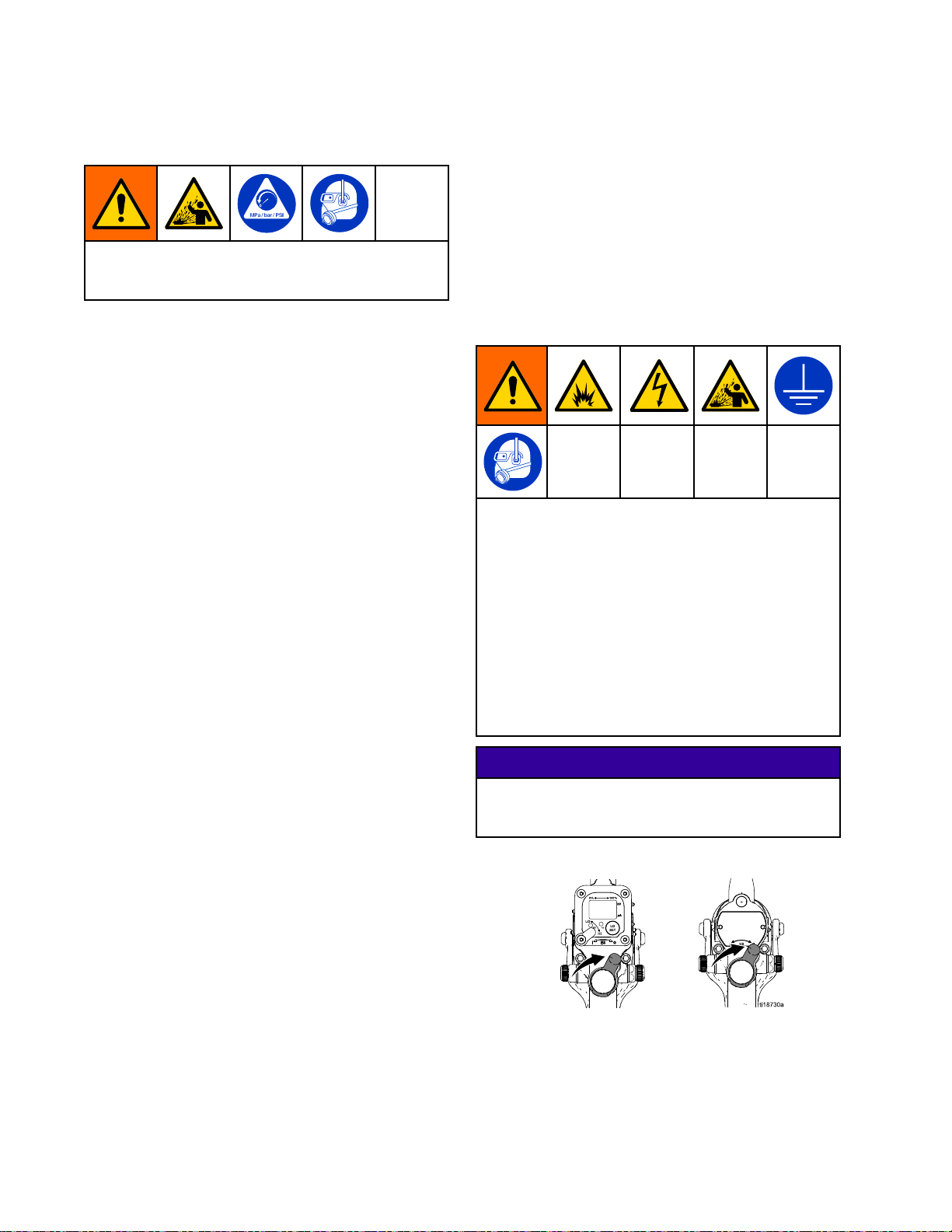
2.TurnOFF(O)theESOn-Offswitch(J).
3.Shutofftheairbleedvalvetothegun.
Toselectadifferent
10.Connecttheuidhosetothegunuidinlet.
11.Flushifneeded.SeeFlushing,page38.
12.Positiontheaircapasneeded.
3A2494P25
Page 26
GunSetup
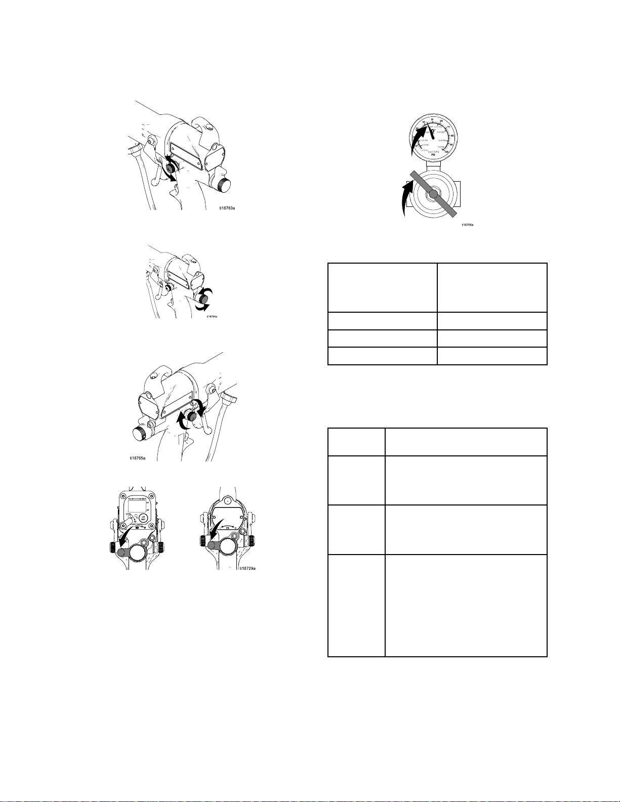
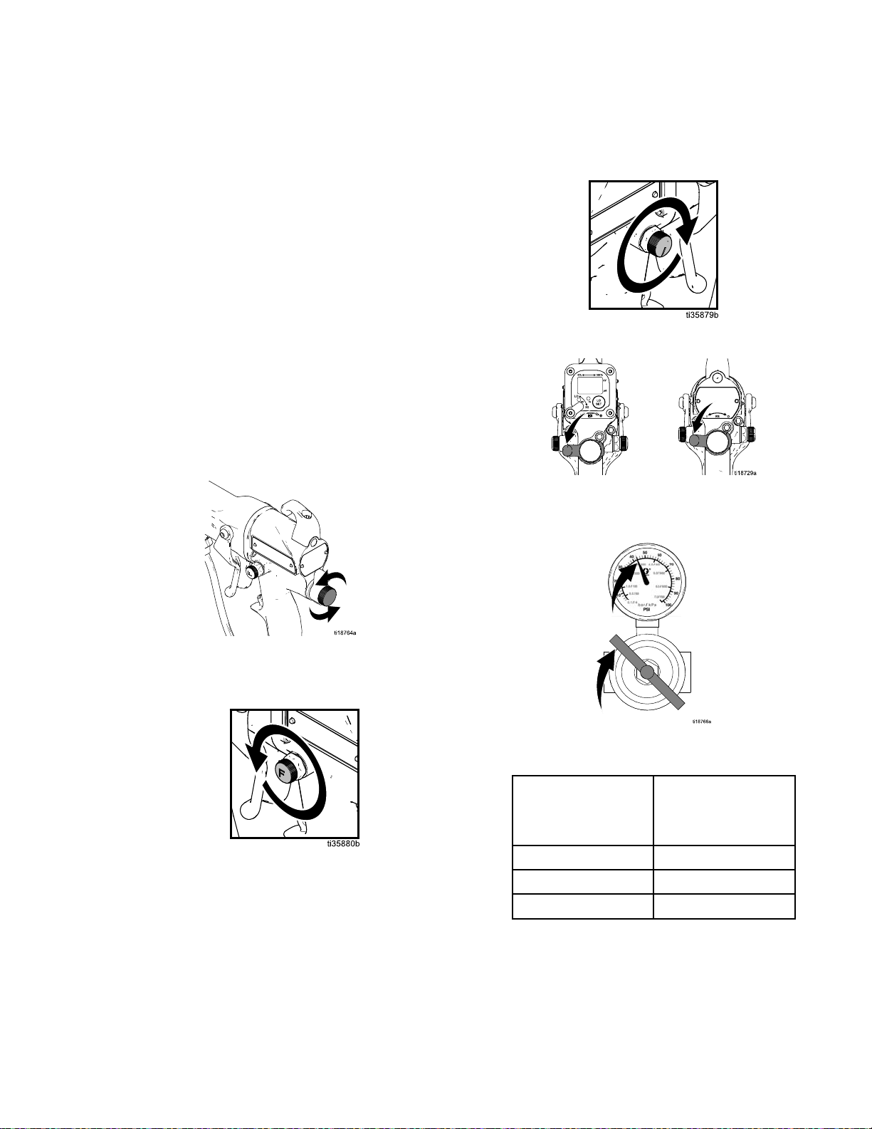
13.Fullyopenthefanairadjustmentvalve(F)
counterclockwise.
14.Fullyopentheuidadjustmentvalve(H)
counterclockwise.
15.Fullyopentheatomizingairrestrictorvalve(G)
clockwise.
17.Setthegunairregulatortodeliveraminimum
45psi(0.32MPa,3.2bar)atthegunwhen
triggered,toensurefullsprayingvoltage.
Table
Table Table
using
using using
mm)
mm) mm)
Pressure
2 22. ..Pressure Pressure
Air
Hose
Air Air
Hose Hose
Length
Length Length
in ininft ftft(m) (m)
5/16
5/16 5/16
diameter
diameter diameter
15(4.6)55(0.38,3.8)
25(7.6)65(0.45,4.5)
50(15.3)80(0.56,5.6)
Drop
Drop Drop
(m)
inch
(8
inch inch
(8 (8
hose
hose hose
Air
Regulator
Air Air
Regulator Regulator
psi
in ininpsi psi
with
gun
with with
gun gun
Setting
Setting Setting
(MPa,
(MPa, (MPa,
bar)
bar) bar)
triggered
triggered triggered
16.TurnON(I)theESOn-Offswitch(J).
18.VerifythattheESindicator(K)[Hzindicatoron
Smartguns]islit.
Table
Table Table
Indicator
Indicator Indicator
Green
Amber
LED
3 33. ..LED LED
Color
Color Color
Red
Indicator
Indicator Indicator
Whenspraying,theindicator
shouldremaingreen,indicating
sufcientairpressuretothe
alternatorturbine.
Iftheindicatorchangestoamber
afteronesecond,theairpressure
istoolow.Increaseairpressure
untiltheindicatorisgreen.
Iftheindicatorchangestored
afteronesecond,theairpressure
istoohigh.Decreaseairpressure
untiltheindicatorisgreen.To
maintainahigherapplicationair
pressure,installESOn/OffValve
RestrictorKit26A160.Adjustthe
pressureasneededtoensurethe
indicatorremainsgreen.
Colors
Colors Colors
Description
Description Description
263A2494P
Page 27
GunSetup
19.Shutofftheairtothegun.TurnOFF(O)theES
On-Offswitch(J).
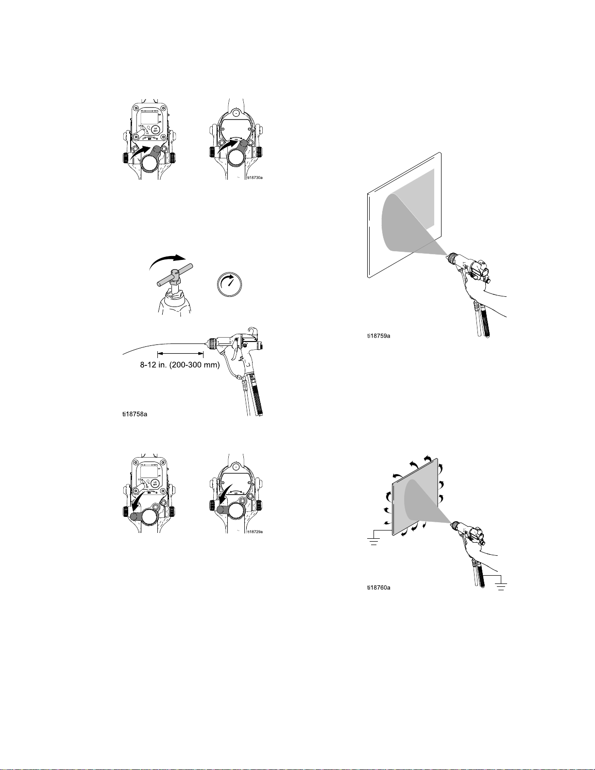
20.Startthepump.Adjusttheuidregulatoruntilthe
streamfromtheguntravels8-12in.(200-300
mm)beforefallingoff.Typically,ifuidpressure
isbelow5psi(.04MPa,0.4bar)orabove30psi
(0.21MPa,2.1bar),achangeofnozzlesizeis
recommended.
22.Sprayatestpattern.Checktheatomization.
•Ifover-atomizationoccursatminimum
pressure,adjusttheatomizingairrestrictor
valve.
•Ifatomizationisinadequate,increaseair
pressureordecreaseuidow.
23.Adjustthefanairadjustmentvalve.
21.Turnontheairtothegun.TurnON(I)theES
On-Offswitch(J).
•Fullyopenthefanairadjustmentvalve,
counterclockwise,forthelongestpattern.
•Turnthevalveclockwisetorestrictthefanair
andcreateashorterpattern.
24.Sprayatestpiece.Examinetheedges
forcoverage.Ifwrapispoor,see
Troubleshooting,page44.
3A2494P
27
Page 28
GunSetup
Soft
Spray
Soft Soft
Spray Spray
Gun
Gun Gun
Setup
Setup Setup
Procedure
Procedure Procedure
Toachieveasoftspraypatternforsmallorlightweight
parts,dothefollowing:
1.Selectasoftspraygunmodel.See
SoftSprayGunModels,page5.
•Toconvertagunforsoftspray,
installasoftsprayaircap.See
AirCapSelectionGuide,page82.
•Forbestresults,installa1.0
mmor1.2mmnozzle.See
FluidNozzleSelectionChart,page79.
2.Followsteps1–14inthe
GunSetupProcedure,page25.
3.Adjusttheatomizingair.Fullyclosetheatomizing
airrestrictorvalve(G)counterclockwise.Then,
opentheatomizingairrestrictorvalve(G)one
halfturntooneturn.
4.TurnON(I)theESOn-Offswitch(J).
Table
Table Table
using
using using
mm)
mm) mm)
6.VerifythattheESindicator(K)[Hzindicatoron
Smartguns]islit.
Table
Table Table
Indicator
Indicator Indicator
Green
Amber
Pressure
4 44. ..Pressure Pressure
Air
Hose
Air Air
Hose Hose
Length
Length Length
Color
Color Color
Red
in ininft ftft(m) (m)
5/16
5/16 5/16
diameter
diameter diameter
15(4.6)55(0.38,3.8)
25(7.6)65(0.45,4.5)
50(15.3)80(0.56,5.6)
LED
5 55. ..LED LED
Drop
Drop Drop
(m)
inch
(8
inch inch
(8 (8
hose
hose hose
Indicator
Indicator Indicator
Whenspraying,theindicator
shouldremaingreen,indicating
sufcientairpressuretothe
alternatorturbine.
Iftheindicatorchangestoamber
afteronesecond,theairpressure
istoolow.Increaseairpressure
untiltheindicatorisgreen.
Iftheindicatorchangestored
afteronesecond,theairpressure
istoohigh.Decreaseairpressure
untiltheindicatorisgreen.To
maintainahigherapplicationair
pressure,installESOn/OffValve
RestrictorKit26A160.Adjustthe
pressureasneededtoensurethe
indicatorremainsgreen.
Colors
Colors Colors
Description
Description Description
Air
Regulator
Air Air
Regulator Regulator
psi
in ininpsi psi
with
gun
with with
gun gun
Setting
Setting Setting
(MPa,
(MPa, (MPa,
triggered
triggered triggered
bar)
bar) bar)
5.Setthegunairregulatortodeliveraminimum
45psi(0.32MPa,3.2bar)atthegunwhen
triggered,toensurefullsprayingvoltage.
7.Continuewithsteps19–24inthe
GunSetupProcedure,page25.
NOTE:
NOTE: NOTE:
productionrateof3.5oz/min(100cc/min).For
bestsoftsprayresults,limittheproductionrate
to7oz/min(200cc/min)orless.
NOTE:
NOTE: NOTE:
much,adjusttheatomizingairrestrictorvalve
(G)counterclockwiseslightlytolimittheairow.
Toimproveatomization,adjusttheatomizingair
restrictorvalve(G)clockwiseslightlytoincrease
theairowordecreasetheuidow.
Thesoftsprayaircapisoptimizedfora
Iftheobjectbeingsprayedismovingtoo
283A2494P
Page 29
GunSetup
HVLP
HVLP HVLP
Mostairqualityauthoritiesacceptelectrostatic
sprayingasthemostefcientprocessandameans
tocomplywithenvironmentalregulation.Follow
theGunSetupProcedure,page25whenspraying
electrostaticallywithanHVLPaircap.
Whenelectrostaticsprayingcannotbeeffectively
usedoncertainpartsormaterials,anHVLPguncan
beusedtocomplywithenvironmentalregulationsin
mostareas.Tobeincompliancetheairpressures
attheaircapmustbelessthan10psi.Follow
theprocedurebelowtosetupthespraygunfor
non-electrostaticHVLPoperation.
1.SelectanHVLPgunmodel.See
2.Followsteps1–12inthe
3.Fullyopentheuidadjustmentvalve(H)
Gun
Gun Gun
HVLPGunModels,page6.
ToconvertagunforHVLP,installanHVLPair
cap.SeeAirCapSelectionGuide,page82.
GunSetupProcedure,page25.
counterclockwise.
Setup
Setup Setup
Procedure
Procedure Procedure
b.Fullyopentheatomizingairrestrictorvalve
(G)clockwise.
c.TurnOFF(I)theESOn-Offswitch(J).
d.Setthegunairregulatortodeliver30
psi(0.21MPa,2.1bar)atthegunwhen
triggered.
4.Adjusttheairintheaircap.
a.Fullyopenthefanairadjustmentvalve(F)
counterclockwise.
Table
Table Table
5.Shutofftheairtothegun.
Pressure
6 66Pressure Pressure
Air
Hose
Air Air
Hose Hose
(m)
in ininft ftft(m) (m)
5/16
inch
5/16 5/16
inch inch
diameter
diameter diameter
15(4.6)43(0.29,3)
25(7.6)50(0.34,3.4)
50(15.3)70(0.48,4.8)
Drop
Drop Drop
Length
Length Length
using
using using
(8
mm)
(8 (8
mm) mm)
hose
hose hose
Air
Regulator
Air Air
Regulator Regulator
Setting
Setting Setting
(MPa,
(MPa, (MPa,
gun
gun gun
psi
in ininpsi psi
bar)
with
bar) bar)
with with
triggered
triggered triggered
3A2494P29
Page 30

GunSetup
6.Startthepump.Adjusttheuidregulatoruntilthe
streamfromtheguntravels8-12in.(200-300
mm)beforefallingoff.Typically,ifuidpressure
isbelow5psi(.04MPa,0.4bar)orabove30psi
(0.21MPa,2.1bar),achangeofnozzlesizeis
recommended.
7.Turnontheairtothegun.
8.Sprayatestpattern.Checktheatomization.
•Ifover-atomizationoccursadjusttheatomizing
airrestrictorvalve.
•Ifatomizationisinadequate,increaseair
pressureordecreaseuidow.
9.Adjustthefanairadjustmentvalve.
•Ifdesired,turnthevalveclockwisetorestrict
thefanairandcreateashorterpattern.
10.VerifythattheaircappressuresmeetHVLP
requirementsof10PSI(0.07MPa,0.7bar)or
lessusingtheHVLPvericationkit25E919.See
manual3A6833.Adjustthefanairadjustment
valve(F)andatomizingairrestrictorvalveto
achieve10PSIorlessasneeded.
303A2494P
Page 31

GunSetup
Round
Round Round
Toachievearoundspraypattern,dothefollowing:
1.Selectaroundspraygunmodelorconvertan
2.Followsteps1–11inthe
3.Fullyopentheuidadjustmentvalve(H)
Spray
Spray Spray
existingguntoroundspray.
•Toselectaroundspraygunmodel,see
RoundSprayGunModels,page5.
•Toconvertagunforroundspray,installa
roundspraykit.SeeRoundSprayAccessories
inGunAccessories,page89.
•Toachieveasoftpatternforsmallparts
orincreasedtransferefciency,selectthe
mediumpatternorsmallpatternmodels.
GunSetupProcedure,page25.
counterclockwise.
Gun
Gun Gun
Setup
Setup Setup
Procedure
Procedure Procedure
5.TurnON(I)theESOn-Offswitch(J).
6.Setthegunairregulatortodeliveraminimum
45psi(0.32MPa,3.2bar)atthegunwhen
triggered,toensurefullsprayingvoltage.
4.Adjusttheairintheaircap.
a.Fullyclosetheatomizingairrestrictorvalve
(G)counterclockwise.Then,openthe
atomizingairrestrictorvalve(G)oneturn.
b.Fullyclosethefanairadjustmentvalve(F)
clockwise.
Table
Table Table
using
using using
mm)
mm) mm)
Pressure
7 77. ..Pressure Pressure
Air
Hose
Air Air
Hose Hose
Length
Length Length
in ininft ftft(m) (m)
5/16
5/16 5/16
diameter
diameter diameter
15(4.6)55(0.38,3.8)
25(7.6)65(0.45,4.5)
50(15.3)80(0.56,5.6)
Drop
Drop Drop
Air
Air Air
(m)
inch
(8
inch inch
(8 (8
hose
hose hose
Regulator
Regulator Regulator
psi
in ininpsi psi
with
gun
with with
gun gun
Setting
Setting Setting
(MPa,
(MPa, (MPa,
bar)
bar) bar)
triggered
triggered triggered
3A2494P31
Page 32

GunSetup
7.VerifythattheESindicator(K)[Hzindicatoron
Smartguns]islit.
Table
Table Table
Indicator
Indicator Indicator
Amber
8.Shutofftheairtothegun.TurnOFF(O)theES
On-Offswitch(J).
LED
8 88. ..LED LED
Color
Color Color
Green
Red
Indicator
Indicator Indicator
Whenspraying,theindicator
shouldremaingreen,indicating
sufcientairpressuretothe
alternatorturbine.
Iftheindicatorchangestoamber
afteronesecond,theairpressure
istoolow.Increaseairpressure
untiltheindicatorisgreen.
Iftheindicatorchangestored
afteronesecond,theairpressure
istoohigh.Decreaseairpressure
untiltheindicatorisgreen.To
maintainahigherapplicationair
pressure,installESOn/OffValve
RestrictorKit26A160.Adjustthe
pressureasneededtoensurethe
indicatorremainsgreen.
Colors
Colors Colors
Description
Description Description
10.Turnontheairtothegun.TurnON(I)theES
On-Offswitch(J).
11.Sprayatestpattern.Checktheatomization.
NOTE:
NOTE: NOTE:
objectbeingsprayedismovingtoomuch,
adjusttheatomizingairrestrictorvalve(G)
counterclockwiseslightlytolimittheairow.To
improveatomization,adjusttheatomizingair
restrictorvalve(G)clockwiseslightlytoincrease
theairowordecreasetheuidow.
Iftheatomizationistoone,orifthe
9.Startthepump.Adjusttheuidregulatorto
achievetheproductionratethatyouwant.
NOTE:
NOTE: NOTE:
aproductionrateof5oz/min(150cc/min).For
bestroundsprayresults,limittheproductionrate
to10oz/min(300cc/min)orless.
Theroundsprayaircapisoptimizedfor
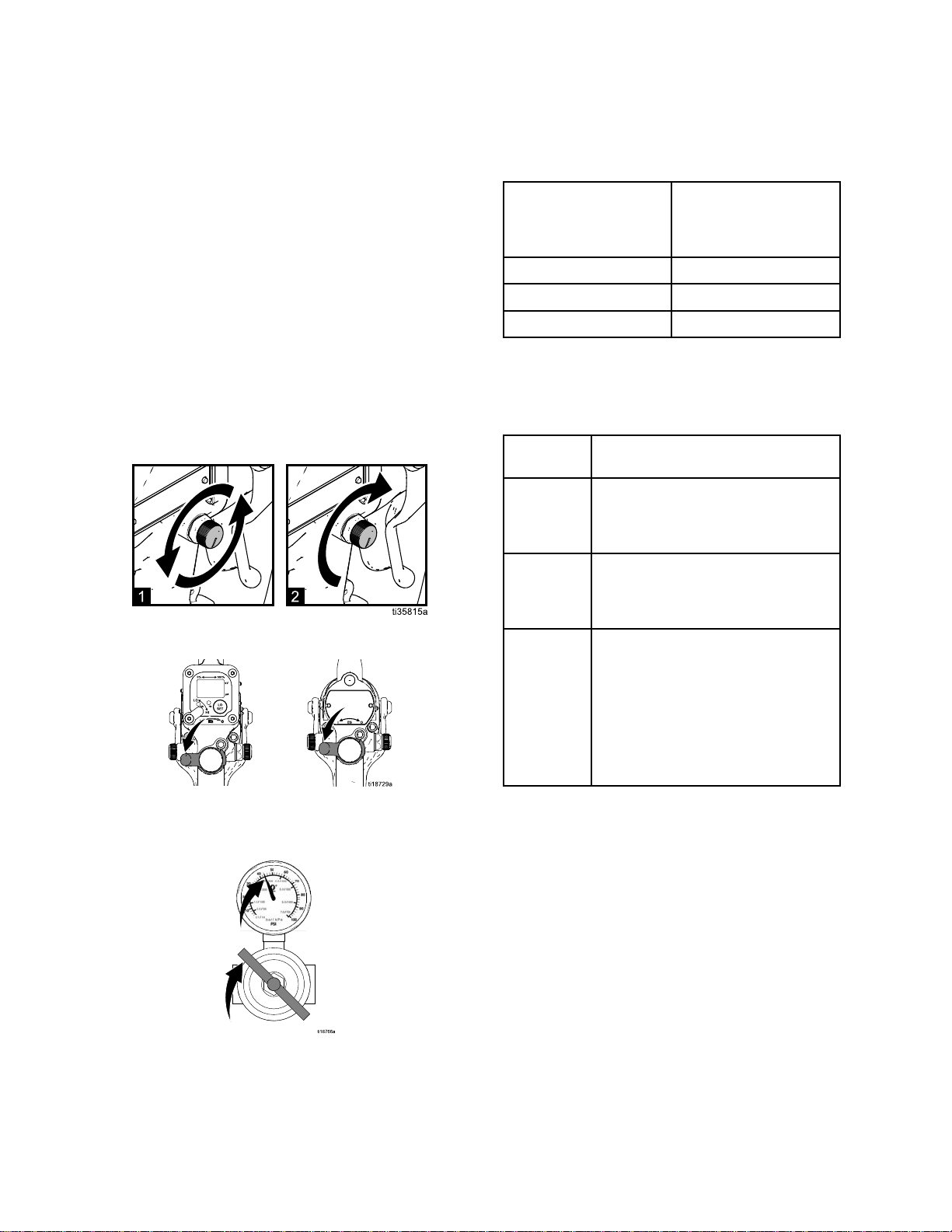
12.Adjustthepatternsize.
•Forthelargestspraypattern,fullyclosethefan
airadjustmentvalve(F)clockwise.
•Forthesmallestspraypattern,fullyopenthe
fanairadjustmentvalve(F)counterclockwise.
13.Sprayatestpiece.Examinetheedges
forcoverage.Ifwrapispoor,see
Troubleshooting,page44.
323A2494P
Page 33

GunSetup
Abrasive
Abrasive Abrasive
NOTE:
NOTE: NOTE:
taskseachday:
•Cleanthegun.SeeCleantheGunDaily,page40.
•Inspecttheelectrodeandreplaceifdamaged.See
ElectrodeReplacement,page49.
Toextendwearlifewithabrasive,metallic,and
extremelyabrasivematerials,dothefollowing:
1.Selectahighconductivityor
xeduidowgunmodel.See
HighConductivityGunModels,page4and
FixedFluidFlowGunModels,page6.
2.Toconvertagunforabrasivematerials:
•Selectahighwear,short,
orhardenedelectrode.See
ElectrodeSelectionChart,page88.
•Selectaprecisionhighwear
orhighwearnozzle.See
FluidNozzleSelectionChart,page79.
Sizethenozzleproperlytoreduceuid
pressurebelow30psi(0.21MPA,2.1bar),
producingan8-12in(200-300mm)uid
stream.
•Use24N632ESOn-OffandFixedFluidValve.
3.Followsteps1–19inthe
GunSetupProcedure,page25.
4.Startthepump.Adjusttheuidregulatoruntilthe
streamfromtheguntravels8-12in.(200-300
mm)beforefallingoff.Typically,ifuidpressure
isbelow5psi(.04MPa,0.4bar)orabove30psi
(0.21MPa,2.1bar),achangeofnozzlesizeis
recommended.
Material
Material Material
Toextendwearlife,performthefollowing
Gun
Gun Gun
Setup
Setup Setup
Procedure
Procedure Procedure
5.Turnontheairtothegun.TurnON(I)theES
On-Offswitch(J).
6.Sprayatestpattern.Checktheatomization.If
over-atomizationoccursatminimumpressure,
adjusttheatomizingairrestrictorvalve.If
atomizationisinadequate,increaseairpressure
ordecreaseuidow.
NOTE:
NOTE: NOTE:
toextendelectrodewirewearlife.Reducethe
guninletairpressureoradjusttheatomizingair
restrictorvalve(G)counterclockwisetoreduce
atomizingairwhentheapplicationallows.
7.Adjustthefanairadjustmentvalve.
•Fullyopenthefanairadjustmentvalve,
•Turnthevalveclockwisetorestrictthefanair
NOTE:
NOTE: NOTE:
extendelectrodewirewearlife.Reducethegun
inletairpressureoradjustthefanairadjustment
valve(F)clockwisetoreducefanairwhenthe
applicationallows.
8.Sprayatestpiece.Examinetheedges
forcoverage.Ifwrapispoor,see
Troubleshooting,page44.
Usetheminimumatomizingairpressure
counterclockwise,forthelongestpattern.
andcreateashorterpattern.
Usetheminimumfanairpressureto
NOTE:
NOTE: NOTE:
knobinthefullowpositionatalltimesor
install24N632ESOn-OffandFixedFluidValve.
Alwaysuseanexternaluidregulator.Donot
usetheuidadjustmentknobtosettheuid
pressure.
Operatethegunwiththeuidadjustment
3A2494P33
Page 34

GunSetup
Check
Check Check
MegohmmeterPartNo.241079(AA-seeFig.16)
isnotapprovedforuseinahazardouslocation.
Toreducetheriskofsparking,donotusethe
megohmmetertocheckelectricalgrounding
unless:
•Thegunhasbeenremovedfromthehazardous
•Orallsprayingdevicesinthehazardous
Failuretofollowthiswarningcouldcausere,
explosion,andelectricshockandresultinserious
injuryandpropertydamage.
GracoPartNo.241079Megohmmeterisavailable
asanaccessorytocheckthatthegunisproperly
grounded.
1.Haveaqualiedelectricianchecktheelectrical
2.TurnOFF(O)theESOn-Offswitch.
Gun
Gun Gun
location;
locationareturnedoff,ventilationfansinthe
hazardouslocationareoperating,andthereare
noammablevaporsinthearea(suchasopen
solventcontainersorfumesfromspraying).
groundingcontinuityofthespraygunandair
hose.
Electrical
Electrical Electrical
Grounding
Grounding Grounding
5.Makesurethegroundedairhose(AH)is
connectedandthehosegroundwireis
connectedtoatrueearthground.
6.Measuretheresistancebetweenthegunhandle
(BB)andatrueearthground(CC).Usean
appliedvoltageof500minimumto1000volts
maximum.Theresistanceshouldnotexceed1
megohm.SeeFig.16.
7.Iftheresistanceisgreaterthan1megohm,check
thetightnessofthegroundconnectionsandbe
suretheairhosegroundwireisconnectedtoa
trueearthground.Iftheresistanceisstilltoo
high,replacetheairhose.
3.Turnofftheairanduidsupplytothegun.Follow
thePressureReliefProcedure,page36.
4.Disconnecttheuidhose.
Figure16CheckGunElectricalGrounding
343A2494P
Page 35

GunSetup
Check
Check Check
Toreducetheriskofre,explosion,orelectric
shock,checktheuidresistivityinanon-hazardous
locationonly.ResistanceMeter722886andProbe
722860arenotapprovedforuseinahazardous
location.
Checkthattheresistivityoftheuidbeingsprayed
meetstherequirementsforanelectrostaticairspray
system.GracoPartNo.722886ResistanceMeter
and722860Probeareavailableasaccessories.
Followtheinstructionsincludedwiththemeterand
probe.
Fluidresistivityreadingsofatleast20megohms-cm
generallyprovidethebestelectrostaticresultsand
arerecommended.
Ahighconductivitykitorhighconductivityhosemay
berequiredforreadingslessthan20megohm-cm.
Table
Table Table
Fluid
Fluid Fluid
Fluid
9 99. ..Fluid Fluid
Resistivity
Resistivity Resistivity
Resistivity
Resistivity Resistivity
Levels
Levels Levels
Check
Check Check
Aviscositycupandstopwatchareneededtocheck
uidviscosity.
1.Completelysubmergetheviscositycupin
2.Watchthestreamofuidcomingfromthebottom
3.Recordtheuidtype,elapsedtime,andsizeof
4.Iftheviscosityistoohighortoolow,contactthe
Flush
Flush Flush
Theequipmentwastestedinuidatthefactory.To
avoidcontaminatingyouruid,ushtheequipment
withacompatiblesolventbeforeusingtheequipment.
SeeFlushing,page38.
Fluid
Fluid Fluid
theuid.Liftthecupoutquickly,startingthe
stopwatchassoonasthecupiscompletely
removed.
ofthecup.Assoonasthereisabreakinthe
stream,shutoffthestopwatch.
theviscositycup.
materialsupplier.Adjustasnecessary.
Before
Before Before
Viscosity
Viscosity Viscosity
Using
Using Using
Equipment
Equipment Equipment
Megohms
Megohms Megohms
1–77–2020–200200–2000
HighConductivity
Kitrecommended
HighConductivity
Kitmaybe
needed
cm
- --cm cm
Bestelectrostatic
results
Goodelectrostatic
results
3A2494P35
Page 36

Operation
Operation
Operation Operation
Pressure
Pressure Pressure
Thisequipmentstayspressurizeduntilpressure
ismanuallyrelieved.Tohelppreventserious
injuryfrompressurizeduid,suchassplashing,
followthePressureReliefProcedurewhenyou
stopsprayingandbeforecleaning,checking,or
servicingtheequipment.
1.TurnOFF(O)theESOn/Offswitch.
2.Turnofftheairbleedvalvestotheuidsource
andtothegun.
Relief
Relief Relief
Procedure
Procedure Procedure
4.Openthepumpdrainvalve,havingawaste
containerreadytocatchthedrainage.Leave
thepumpdrainvalveopenuntilyouareready
tosprayagain.
5.Ifthenozzleorhoseiscompletelycloggedor
pressureisnotfullyrelieved,slowlyloosenthe
hoseendcoupling.Nowclearthenozzleorhose.
3.Triggerthegunintoagroundedmetalwaste
containertorelievetheuidpressure.
363A2494P
Page 37

Operation
Startup
Startup Startup
FollowallstepsunderGunSetupProcedure,page25.
Beforeoperatingthesystem,checkthefollowinglist
dailytoensuresafe,efcientoperation.
•Alloperatorsareproperlytrainedtosafelyoperate
anelectrostaticairspraysystemasinstructedin
thismanual.
•Alloperatorsaretrainedinthe
PressureReliefProcedure,page36.
•Thewarningsignprovidedwiththegunismounted
inthesprayareawhereitcanbeeasilyseenand
readbyalloperators.
•Thesystemisthoroughlygroundedandthe
operatorandallpersonsenteringthesprayarea
areproperlygrounded.SeeGrounding,page21.
•Theconditionofthegun’selectrical
componentshasbeencheckedasinstructedin
ElectricalTests,page42.
•Ventilationfansareoperatingproperly.
•Workpiecehangersarecleanandgrounded.
•Alldebris(includingammableuidsandrags)is
removedfromthesprayarea.
•Allammableuidsinthespraybootharein
approved,groundedcontainers.
•Allconductiveobjectsinthesprayareaare
electricallygroundedandtheoorofthespray
areaiselectricallyconductiveandgrounded.
Shutdown
Shutdown Shutdown
Toreducetheriskofaninjury,followthe
PressureReliefProcedure,page36wheneveryou
areinstructedtorelievethepressure.
1.Flushthegun.Followthestepsin
Flushing,page38.
2.FollowthePressureReliefProcedure,page36.
3.Hangthegunfromitshook,withthenozzle
pointingdown.
3A2494P37
Page 38
Maintenance
Maintenance
Maintenance Maintenance
Toreducetheriskofaninjury,followthe
PressureReliefProcedure,page36,whenever
youareinstructedtorelievethepressure.
Daily
Daily Daily
Checkthefollowinglistdailyuponcompletionof
equipmentusage.
Care
Care Care
Flushthegun.SeeFlushing,page38.
Cleantheuidandairlinelters.
Cleantheoutsideofthegun.See
CleantheGunDaily,page40.
Cleantheaircapanduidnozzledaily,
ataminimum.Someapplicationsrequire
morefrequentcleaning.Replacethespray
tipandaircapiftheyaredamaged.See
CleantheGunDaily,page40.
Checktheelectrodeandreplace
ifbrokenordamaged.See
ElectrodeReplacement,page49.
Checkforuidleakagefromthegunanduid
hoses.Tightenttingsorreplaceequipment
asneeded.
Checkelectricalgrounding.See
CheckGunElectricalGrounding,page34.
and
Cleaning
and and
Cleaning Cleaning
Checklist
Checklist Checklist
Flushing
Flushing Flushing
•Flushbeforechanginguids,beforeuidcandry
intheequipment,attheendoftheday,before
storing,andbeforerepairingequipment.
•Flushatthelowestpressurepossible.Check
connectorsforleaksandtightenasnecessary.
•Flushwithauidthatiscompatiblewiththeuid
beingdispensedandtheequipmentwettedparts.
Toreducetheriskofre,explosion,orelectric
shock:
•TurnOFF(O)theESOn-Offswitchbefore
ushingthegun.
•Alwaysgroundequipmentandwastecontainers.
•Flushequipmentonlyinawell-ventilatedarea.
•UseonlyGroupIIAushingmaterials.
Non-ignitableuidsarepreferred.
•Toavoidstaticsparkingandinjuryfrom
splashing,alwaysushatthelowestpossible
pressure.
NOTICE
NOTICE NOTICE
Donotusemethylenechlorideasaushingor
cleaningsolventwiththisgunasitwilldamage
nyloncomponents.
1.TurnOFF(O)theESOn-Offswitch.
383A2494P
Page 39

Maintenance
2.FollowthePressureReliefProcedure,page36.
3.Changetheuidsourcetosolvent,ordisconnect
theuidlineandconnectasolventsupplyline
tothegun.
4.Pointthegunintoagroundedmetalpail.Flush
untilcleansolventowsfromthegun.
5.FollowthePressureReliefProcedure,page36.
6.Shutoffordisconnectthesolventline.
7.Hangthegunfromitshook,withthenozzle
pointingdown.
8.Whenreadytosprayagain,reconnect
theuidsupplyline.Followthe
GunSetupProcedure,page25.
3A2494P39
Page 40

Maintenance
Clean
Clean Clean
•Cleanallpartswithanon-conductive,compatible
•Fluidintheairpassagescouldcausethegunto
1.TurnOFF(O)theESOn-Offswitch.
2.Flushthegun.Followthestepsin
3.FollowthePressureReliefProcedure,page36.
the
Gun
the the
Gun Gun
solvent.Conductivesolventscancausethegun
tomalfunction.
malfunctionandcoulddrawcurrentandreduce
theelectrostaticeffect.Fluidinthepowersupply
cavitycanreducetheturbinelife.Whenever
possible,pointthegundownwhencleaningit.
Donotuseanycleaningmethodwhichcould
allowuidintothegunairpassages.
Flushing,page38.
Daily
Daily Daily
NOTICE
NOTICE NOTICE
4.Cleantheoutsideofthegunwithacompatible
solvent.Useasoftcloth.Pointthegundownto
preventsolventfromenteringthegunpassages.
Donotimmersethegun.
403A2494P
Page 41

Maintenance
5.Cleantheaircap.
a.Removetheaircap.
b.Cleantheaircap,retainingring,andnozzle
withasoftbrushandcompatiblesolvent.
c.Ifnecessary,useatoothpickorothersoft
tooltocleantheaircapholes.Donotuse
metaltools.
Daily
Daily Daily
1.FollowthePressureReliefProcedure,page36.
2.Cleantheuidandairlters.
3.Checkforuidleaks.Tightenallttings.
4.Cleanworkpiecehangers.Usenon-sparking
5.Checkthemovementofthetriggerandvalves.
System
System System
tools.
Lubricateifnecessary.
Care
Care Care
d.Reinstalltheaircap.Tightensecurely.
6.CheckGunElectricalGrounding,page34.
7.Hangthegunfromitshook,withthenozzle
pointingdown.
3A2494P
41
Page 42

ElectricalTests
Electrical
Electrical Electrical
Electricalcomponentsinsidethegunaffect
performanceandsafety.Usethefollowing
procedurestotesttheconditionofthepowersupply
andgunbody,andelectricalcontinuitybetween
components.
UsemegohmmeterPartNo.241079(AA)andan
appliedvoltageof500V.Connecttheleadsas
shown.
MegohmmeterPartNo.241079(AA-seeFig.17)
isnotapprovedforuseinahazardouslocation.
Toreducetheriskofsparking,donotusethe
megohmmetertocheckelectricalgrounding
unless:
•Thegunhasbeenremovedfromthehazardous
location;
•Orallsprayingdevicesinthehazardous
locationareturnedoff,ventilationfansinthe
hazardouslocationareoperating,andthereare
noammablevaporsinthearea(suchasopen
solventcontainersorfumesfromspraying).
Tests
Tests Tests
Test
Test Test
1.Flushanddrytheuidpassage.
2.For For
3.For For
Ifoutsidethisrange,testthegun
untriggered.Ifstilloutsidethisrange,goto
TestPowerSupplyResistance,page43.Ifinrange,
seeElectricalTroubleshooting,page46forother
possiblecausesofpoorperformance.
Gun
Gun Gun
For
L40T15
L40T15 L40T15
verifythatthemetalpininthebarrelisproperly
grounded.Measureresistancebetweenthe
metalpin(GP)andtheairswivel(21).The
resistanceshouldbelessthan100ohms.Ifthe
resistanceis100ohmsormore,replacethegun
body.
For
resistancebetweentheelectrodeneedletip(3)
andtheairswivel(21).Theresistanceshouldbe:
•75–120megohmsfor40kVguns
•104–148megohmsfor60kVguns
•148–193megohmsfor85kVguns
Resistance
Resistance Resistance
Model
Model Model
all
all all
guns
guns guns
guns:
guns: guns:
L40M14,
L40M14, L40M14,
only:
only: only:
Triggerthegunandmeasure
L40T14,
L40T14, L40T14,
Testthebarrelcontinuityto
L40M15,
L40M15, L40M15,
and
and and
Failuretofollowthiswarningcouldcausere,
explosion,andelectricshockandresultinserious
injuryandpropertydamage.
Figure17TestGunResistance
42
3A2494P
Page 43

ElectricalTests
Test
Test Test
1.Removethepowersupply(11).Followthesteps
2.Removethealternator(15)
3.Measureresistancefromthepowersupply's
4.Ifoutsidethisrange,replacethe
5.Ifyoustillhaveproblems,referto
6.Besurethespring(11a)isinplacebefore
Power
Power Power
inPowerSupplyRemovalandReplacement,
page53.
fromthepowersupply.See
AlternatorRemovalandReplacement,page54.
groundstrips(EE)tothespring(11a).The
resistanceshouldbe:
•60–85megohmsfor40kVguns
•86–110megohmsfor60kVguns
•130–160megohmsfor85kVguns
powersupply.Ifinrange,goto
TestElectrodeResistance,page43.
ElectricalTroubleshooting,page46for
otherpossiblecausesofpoorperformance,or
contactyourGracodistributor.
reinstallingthepowersupply.
Supply
Supply Supply
Resistance
Resistance Resistance
Test
Test Test
Removetheelectrode(3).See
ElectrodeReplacement,page49.Measure
theresistancebetweenthecontact(HH)andthe
electrodewire(GG).Theresistanceshouldbe8-30
megohms.Ifoutofrange,replacetheelectrode.
NOTE:
NOTE: NOTE:
testingthepowersupplyandelectrode:
•Checkthattheconductiveo-ring(4a)ismaking
•Checkthatthepowersupplyspring(11a)ismaking
Electrode
Electrode Electrode
Ifthegunresistanceisstilloutofrangeafter
contactwiththebarrelpin.
contactwiththebarrelpin.
Resistance
Resistance Resistance
Figure18TestPowerSupplyResistance
Figure19TestElectrodeResistance
3A2494P43
Page 44

Troubleshooting
Troubleshooting
Troubleshooting Troubleshooting
Installingandservicingthisequipmentrequires
accesstopartswhichmaycauseanelectricshock
orotherseriousinjuryiftheworkisnotperformed
properly.Donotinstallorrepairthisequipment
unlessyouaretrainedandqualied.
CheckallpossibleremediesintheTroubleshootingChartbeforedisassemblingthegun.
Spray
Spray Spray
Somespraypatternproblemsarecausedbytheimproperbalancebetweenairanduid.
Problem
Problem Problem
Flutteringorspittingspray.
Improperspraypattern. Damagedordirtynozzleoraircap.
Pattern
Pattern Pattern
Troubleshooting
Troubleshooting Troubleshooting
Cause
Cause Cause
Nouid.Rellsupply.
Loose,dirty,damaged
nozzle/seat.
Airinuidsupply.Checkuidsource.Rell.
Toreducetheriskofaninjury,followthe
PressureReliefProcedure,page36,whenever
youareinstructedtorelievethepressure.
Solution
Solution Solution
Cleanorreplacenozzle.See
CleantheGunDaily,page40,or
AirCapandNozzleReplacement,
page48.
Cleanorreplace.SeeAirCapand
NozzleReplacement,page48.
Fluidbuilduponaircapornozzle.
Fanairpressuretoohigh.Decrease.
Fluidtoothin.Increaseviscosity.
Fluidpressuretoolow.Increase.
Fanairpressuretoolow.Increase.
Fluidtoothick.Reduceviscosity.
Toomuchuid.Decreaseow.
Didnotapply50%overlap.Overlapstrokes50%. Streaks.
Dirtyordamagedaircap.
44
Clean.See
CleantheGunDaily,page40.
Cleanorreplaceaircap.See
CleantheGunDaily,page40,or
AirCapandNozzleReplacement,
page48.
3A2494P
Page 45

Troubleshooting
Gun
Gun Gun
Operation
Operation Operation
Problem
Problem Problem
Excessivesprayfog.
“OrangePeel”nish.
Fluidleaksfromtheuidpacking
area.
Airleaksfromthefrontofthegun.
Fluidleakagefromthefrontofthe
gun.
Troubleshooting
Troubleshooting Troubleshooting
Cause
Cause Cause
Atomizingairpressuretoohigh.
Fluidtoothin,oruidowistoo
low.
Atomizingairpressuretoolow.
Poorlymixedorltereduid.Remixorrelteruid.
Fluidtoothick.Reduceviscosity.
Wornpackingsorrod.
Airvalveisnotseatingproperly.
Wornordamageduidpacking
rodorelectrode.
Solution
Solution Solution
Closerestrictorvalvepartway,or
decreaseairpressureaslowas
possible;minimum45psi(0.32
MPa,3.2bar)neededatgunfor
fullvoltage.
Increaseviscosityorincreaseuid
owrate.
Openatomizingairvalvemoreor
increasegunairinletpressure;
uselowestairpressurenecessary.
Replacepackings.See
PackingRodRepair,page50.
Replaceairvalve.See
AirValveRepair,page60.
Replacepackingrod(2e)
orelectrode(3).See
PackingRodRepair,page50or
ElectrodeReplacement,page49.
Gundoesnotspray.
Dirtyaircap.
Excessivepaintwrapbackto
operator.
Wornuidnozzleseat.Replacenozzle(4).See
AirCapandNozzleReplacement,
page48.
Looseuidnozzle.
Damagednozzleo-ring.
Lowuidsupply.Adduidifnecessary.
Dirtyorcloggeduidnozzle.Clean.See
Closedordamageduid
adjustmentvalve.
Misalignedaircapanduidnozzle.Cleanuidbuildupoffaircap
Poorgrounding.
Incorrectdistancefromguntopart.Shouldbe8–12in.(200–300mm).
Tighten.
Replaceo-ring.SeeAirCapand
NozzleReplacement,page48.
CleantheGunDaily,page40.
Openvalve,orsee
ESOn-OffandFluidAdjustment
ValveRepair,page59.
anduidnozzleseat.See
CleantheGunDaily,page40.
SeeGrounding,page21.
3A2494P45
Page 46

Troubleshooting
Electrical
Electrical Electrical
Problem
Problem Problem
Poorwrap.
lit.
Troubleshooting
Troubleshooting Troubleshooting
Cause
Cause Cause
ESOn/OffswitchisOFF(O).TurnON(I).
Gunairpressuretoolow(ESindicator
isamber).
Atomizingairpressuretoohigh.Decrease.
Incorrectdistancefromguntopart.Shouldbe8-12in.(200-300mm).
Poorlygroundedparts.Resistancemustbe1megohmorless.
Faultygunresistance.
Lowuidresistivity.SeeCheckFluidResistivity,page35.
Fluidleaksfromthepacking(2c)and
causesashort.
Faultyalternator.
ESOn/OffswitchisOFF(O).TurnON(I). ESorHzindicatorisnot
Nopower.
Solution
Solution Solution
Checkairpressuretogun;minimum45
psi(0.32MPa,3.2bar)neededatgun
forfullvoltage.
Cleanworkpiecehangers.
SeeTestGunResistance,page42.
SeePackingRodRepair,page50.
SeeAlternatorRemovaland
Replacement,page54.
Checkpowersupply,alternator,andalternatorribboncable.
SeePowerSupplyRemovaland
Replacement,page53andAlternator
RemovalandReplacement,page54.
Operatorgetsshockfrom
workpiece.
Voltage/currentdisplay
staysred(Smartguns
only).
ESorHZindicatoris
amber.
ESorHzindicatorisred.
Errordisplayappears
andHzindicatorisred
(Smartgunsonly).
Operatornotgroundedorisnear
ungroundedobject.
Gunnotgrounded.SeeCheckGunElectrical
Workpiecenotgrounded.Resistancemustbe1megohmorless.
Gunistooclosetothepartbeing
sprayed.
Checkuidresistivity.SeeCheckFluidResistivity,page35.
Dirtygun.
Alternatorspeedistoolow.Increaseairpressureuntilindicator
Alternatorspeedistoohigh.Decreaseairpressureuntilindicatoris
Smartmodulehaslostcommunication
withthepowersupply.
SeeGrounding,page21. Operatorgetsmildshock.
Grounding,page34,and
TestGunResistance,page42.
Cleanworkpiecehangers.
Gunshouldbe8–12in.(200–300mm)
fromthepart.
SeeCleantheGunDaily,page40.
isgreen.Toavoidover-atomization,
usetheatomizingairrestrictorvalveto
reducetheatomizingairtotheaircap.
green.
Checkforgoodconnections
betweentheSmartModule
andthepowersupply.See
SmartModuleReplacement,page61a-
ndPowerSupplyRemovaland
Replacement,page53.
463A2494P
Page 47

Repair
Repair
Repair Repair
Prepare
Prepare Prepare
Installingandrepairingthisequipmentrequires
accesstopartsthatmaycauseelectricshockor
otherseriousinjuryiftheworkisnotperformed
properly.Donotinstallorservicethisequipment
unlessyouaretrainedandqualied.
Toreducetheriskofinjury,followthePressure
ReliefProcedurebeforecheckingorservicingany
partofthesystemandwheneveryouareinstructed
torelievethepressure.
•Checkallpossibleremedies
inTroubleshooting,page44beforedisassembling
thegun.
•Useavisewithpaddedjawstopreventdamage
toplasticparts.
the
Gun
the the
Gun Gun
for
Service
for for
Service Service
•Lubricatesomepackingrodparts(2)andcertain
uidttingswithdielectricgrease(44),asspecied
inthetext.
•Lightlylubricateo-ringsandsealswithnon-silicone
grease.OrderPartNo.111265Lubricant.Donot
over-lubricate.
•OnlyusegenuineGracoparts.Donotmixoruse
partsfromotherProGunmodels.
•AirSealRepairKit24N789isavailable.The
kitmustbepurchasedseparately.Kitpartsare
markedwithanasterisk,forexample(6a*).
•FluidSealRepairKit24N790isavailable.The
kitmustbepurchasedseparately.Kitpartsare
markedwithasymbol,forexample(2a‡).
1.Flushthegun.Followthestepsin
Flushing,page38.
2.Relievethepressure.Followthe
PressureReliefProcedure,page36.
3.Disconnectthegunairanduidlines.
4.Removethegunfromtheworksite.Repairarea
mustbeclean.
3A2494P
47
Page 48

Repair
Air
Cap
Air Air
Cap Cap
and
Nozzle
and and
Nozzle Nozzle
Replacement
Replacement Replacement
NOTICE
NOTICE NOTICE
Triggerthegunwhileremovingthenozzletohelp
drainthegunandpreventanypaintorsolventleft
inthegunfromenteringtheairpassages.
1.Followthestepsin
PreparetheGunforService,page47.
2.Removetheretainingring(6)andaircap(5).
3.Triggerthegunwhileremovingtheuidnozzle
(4)assemblywiththemulti-tool(41).
Thenozzlecontactring(4a)isaconductive
contactring,notasealingo-ring.Toreduce
theriskofsparkingorelectricshock,donot
removethenozzlecontactring(4a)exceptto
replaceitandneveroperatethegunwithout
thecontactringinplace.Donotreplacethe
contactringwithanythingbutagenuineGraco
part.
NOTE:
NOTE: NOTE:
111265,onthesmallo-ring(4b).Donot
over-lubricate.Donotlubricatetheconductive
contactring(4a).Excessivegreasecanmixwith
paintandblemishthenishontheworkpiece.
4.Makesuretheconductivecontactring(4a)and
thesmallo-ring(4b)areinplaceonthenozzle
(4).Lightlylubricatethesmallo-ring(4b).
NOTE:
NOTE: NOTE:
showsomewearatthepointwhereitmakes
contactwiththebarrelpin.Thisisnormaland
doesnotrequirereplacement.
5.Makesuretheelectrodeneedle(3)isnger-tight.
6.Triggerthegunwhileinstallingtheuidnozzle
(4)withthemulti-tool(41).Tightenuntiltheuid
nozzleseatsinthegunbarrel(1/8to1/4turn
pasthand-tight).
Usenon-siliconegrease,PartNo.
Theconductivecontactring(4a)may
7.Installtheaircap(5)andretainingring(6).Make
suretheu-cup(6a*)isinplacewiththelipsfacing
forward.
8.FollowthestepsinTestGunResistance,page42.
Figure20AirCapandNozzleReplacement
483A2494P
Page 49

Repair
Electrode
Electrode Electrode
1.Followthestepsin
PreparetheGunforService,page47.
2.Removetheaircapandnozzle.See
AirCapandNozzleReplacement,page48.
3.Unscrewtheelectrode(3)withthemulti-tool(41).
4.Applylow-strength(purple)threadlockertothe
electrodeandpackingrodthreads.Installthe
electrodenger-tight.Donotovertighten.
5.Installtheuidnozzleandaircap.See
AirCapandNozzleReplacement,page48.
Toavoiddamagingtheplasticthreads,bevery
carefulwheninstallingtheelectrode.
6.FollowthestepsinTestGunResistance,page42.
Replacement
Replacement Replacement
NOTICE
NOTICE NOTICE
Figure21ElectrodeReplacement
3A2494P49
Page 50

Repair
Fluid
Fluid Fluid
1.Followthestepsin
2.Removetheaircapanduidnozzle.See
3.Removetheelectrode.See
4.Loosenthetriggerscrews(13)andremovethe
5.Removethepackingrod(2),usingthemulti-tool
6.Checkallpartsforwearordamageandreplace
Packing
Packing Packing
PreparetheGunforService,page47.
AirCapandNozzleReplacement,page48.
ElectrodeReplacement,page49.
trigger(12).
(41).Removethespring(17).
ifnecessary.
Rod
Removal
Rod Rod
Removal Removal
Packing
Packing Packing
NOTE:
NOTE: NOTE:
partsorasanassembly.
Adjust
Adjust Adjust
NOTE:
NOTE: NOTE:
isdischargedandtheuidstopsbeforetheairow
stops.Thepackingrodassemblyispre-adjustedat
thefactoryforproperairleadandlag.Adjustonly
ifnecessary,asfollows.
1.Removethespring(17)fromthenut(2k).
2.Useahexwrenchtoholdtheendofthepacking
rod.Turnbothadjustmentnuts(2j,2k)outto
increasethelead/lagtimefortheairow.The
recommendedadjustmentisonehalfturnand
notmorethanonefullturn.
Rod
Rod Rod
Youmayreplacethepackingrodasindividual
the
the the
Thegunbeginsemittingairbeforetheuid
Repair
Repair Repair
Air
Flow
Lead
and
Air Air
Flow Flow
Lead Lead
Lag
and and
Lag Lag
Figure22FluidPackingRodRemoval
3.Tightenthenutstogethertoxtheminthenew
position.
503A2494P
Page 51

Repair
Reassemble
Reassemble Reassemble
NOTE:
NOTE: NOTE:
gunbarrel,makesuretheinternalsurfacesofthe
barrelareclean.Removeanyresiduewithasoft
brushorcloth.Checktheinsideofthebarrelfor
marksfromhighvoltagearcing.Ifmarksarepresent,
replacethebarrel.
1.Placethepackingnut(2f)andseal(2b‡)onthe
2.Filltheinnercavityofthespacer(2h‡)with
3.Placetheuidpacking(2c‡)onthepackingrod
Beforeinstallingtheuidpackingrodintothe
uidrod(2e).Flatsonthepackingnutmustface
thebackoftheuidrod.Thesealo-ringmust
faceawayfromthepackingnut.
dielectricgrease(44).Placethespaceronthe
uidrod(2e)inthedirectionshown.Generously
applydielectricgreasetotheoutsideofthe
spacer.
(2e)withitslipsfacingthefrontoftherod.Install
theneedlepacking(2d‡)withthemaleend
towardtheuidpacking,theninstallthehousing
(2g).
the
Packing
the the
Packing Packing
Rod
Rod Rod
4.Lightlytightenthepackingnut(2f).Thepacking
nutisproperlytightenedwhenthereis3lb(13.3
N)ofdragforcewhenslidingthepackinghousing
(2g)assemblyalongtherod.Tightenorloosen
thepackingnutasneeded.
5.Installtheo-ring(2a‡)ontheoutsideofhousing
(2g).Lubricatetheo-ringwithnon-silicone
grease,PartNo.111265.Donotover-lubricate.
6.Installthespring(17)againstthenut(2j)as
shown.
7.Installthepackingrodassembly(2)intothe
gunbarrel.Usingthemulti-tool(41),tightenthe
assemblyuntiljustsnug.
8.Installtheelectrode.See
ElectrodeReplacement,page49,step4.
9.Installthenozzleandaircap.See
AirCapandNozzleReplacement,page48,
steps5–7.
10.Installthetrigger(12)andscrews(13).
11.FollowthestepsinTestGunResistance,page42.
Figure23PackingRod
3A2494P51
Page 52

Repair
Barrel
Barrel Barrel
1.Followthestepsin
2.Carefullyloosenthenut(N)fromthebracketuid
3.Loosenthetwoscrews(27).
4.Holdthegunhandle(16)withonehandandpull
NOTE:
NOTE: NOTE:
removethealternator/powersupplyassemblyfrom
thebarrel.
Removal
Removal Removal
PreparetheGunforService,page47.
tting(20).Pullthetube(T)outofthetting.
Makesurebothferrules(7,8)andthenutstay
withthetube.
NOTICE
NOTICE NOTICE
Toavoiddamagingthepowersupply(11),pull
thegunbarrel(1)straightawayfromthegun
handle(16).Ifnecessary,gentlymovethegun
barrelfromsidetosidetofreeitfromthegun
handle.
thebarrel(1)straightoffthehandle.
Ifthepowersupplyremainsinthebarrel,
Barrel
Barrel Barrel
1.Besurethegasket(28*)andgroundingspring
2.Makesurethespring(11a)isinplaceonthetipof
3.Tightenthetwoscrews(27)oppositelyand
4.Assembletheuidtube(T)intothebrackettting
5.FollowthestepsinTestGunResistance,page42.
Installation
Installation Installation
(18)areinplace.Makesurethegasketair
holesarealignedproperly.Replacethegasketif
damaged.
thepowersupply(11).Liberally Liberally
grease(44)tothetipofthepowersupply.Place
thebarrel(1)overthepowersupplyandontothe
gunhandle(16).
evenly(aboutahalfturnpastsnugor15–25in-lb,
1.7–2.8N•m).
Toavoiddamagingthegunbarrel,donot
over-tightenthescrews(27).
(20).Ensurethattheferrules(7,8)areinplace.
Tightenthenut(N)securelyontothetting.
Makesurethetopttingremainstight.
Liberally
NOTICE
NOTICE NOTICE
applydielectric
Figure24BarrelRemoval
523A2494P
Figure25BarrelInstallation
Page 53
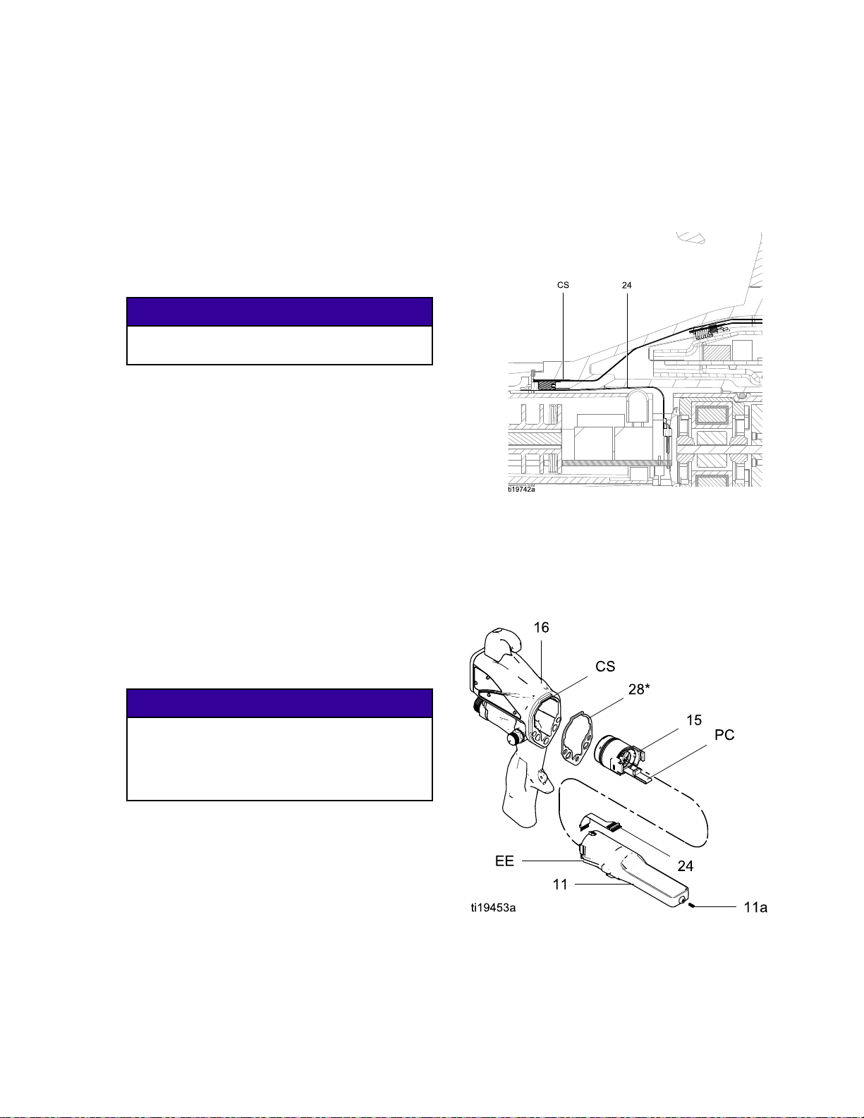
Repair
Power
Power Power
Replacement
Replacement Replacement
•Inspectthegunhandlepowersupplycavityfordirt
ormoisture.Cleanwithaclean,dryrag.
•Donotexposegasket(28)tosolvents.Replace
thegasketifdamaged.
1.Followthestepsin
2.FollowthestepsinBarrelRemoval,page52.
3.Graspthepowersupply(11)withyourhand.
4.Inspectthepowersupplyandalternatorfor
5.Toseparatethepowersupply(11)fromthe
6.Followthestepsin
Supply
Supply Supply
PreparetheGunforService,page47.
Becarefulwhenhandlingthepowersupply
(11)toavoiddamagingit.
Withagentlesidetosidemotion,freethepower
supply/alternatorassemblyfromthegunhandle
(16),thencarefullypullitstraightout.
Modelsonly,
fromthesocketatthetopofthehandle.
damage.
alternator(15),disconnectthe3-wireribbon
connector(PC)fromthepowersupply.
Modelsonly,
(24)fromthepowersupply.Slidethealternator
upandoffthepowersupply.
TestPowerSupplyResistance,page43.
Replacethepowersupplyifnecessary.
Torepairthealternator,see
AlternatorRemovalandReplacement,page54.
Removal
Removal Removal
NOTICE
NOTICE NOTICE
disconnecttheexiblecircuit(24)
disconnectthe6–pinexiblecircuit
and
and and
OnSmart
OnSmart
9.Insertthepowersupply/alternatorassemblyin
thegunhandle(16).Makesurethegroundstrips
(EE)makecontactwiththehandle.OnSmart
models,aligntheconnectorofthe6–pinexible
circuit(24)withthesocket(CS)atthetopofthe
handle.Pushtheconnectorsecurelyintothe
socketasyouslidethepowersupply/alternator
assemblyintothehandle.
Figure26ConnectFlexibleCircuit
10.Makesurethegasket(28*),groundspring(18),
andpowersupplyspring(11a)areinplace.
Assemblethebarrel(1)tothehandle(16).See
BarrelInstallation,page52.
11.FollowthestepsinTestGunResistance,page42.
NOTICE
NOTICE NOTICE
Topreventdamagetothecableandpossible
interruptionofthegroundcontinuity,bendthe
alternator’s3-wireribboncable(PC)upward
andback,sothebendfacesthepowersupply
andtheconnectorisatthetop.
7.
Smartmodelsonly:
circuit(24)tothepowersupply.
8.Connectthe3-wireribbonconnector(PC)tothe
powersupply.Tucktheribbonforward,under
thepowersupply.Slidethealternator(15)down
ontothepowersupply(11).
3A2494P53
connectthe6–pinexible
Figure27PowerSupply
Page 54

Repair
Alternator
Alternator Alternator
NOTE:
NOTE: NOTE:
ofoperation.OrderPartNo.24N706BearingKit.
Partsincludedinthekitaremarkedwithasymbol(♦).
1.Followthestepsin
2.Removethepowersupply/alternatorassembly
3.Measureresistancebetweenthetwoouter
4.Usingaatbladescrewdriver,prytheclip(15h)
5.Ifnecessary,rotatethefan(15e)soitsblades
Replacealternatorbearingsafter2000hours
PreparetheGunforService,page47.
anddisconnectthealternator.SeePowerSupply
RemovalandReplacement,page53.
terminalsofthe3-wireconnector(PC);itshould
be2.0–6.0ohms.Ifoutsidethisrange,replace
thealternatorcoil(15a).
offthehousing(15d).Removethecap(15f),
usingathinbladeorscrewdriver.
clearthefourbearingtabs(T)ofthehousing
(15d).
Removal
Removal Removal
and
Replacement
and and
Replacement Replacement
6.Pushthefanandcoilassembly(15a)outthe
frontofthehousing(15d).
Figure29AlternatorCross-Section
(Ref.28♦isnotshowninthegure.)
Figure28FanOrientation
NOTICE
NOTICE NOTICE
Donotscratchordamagethemagnet(M)or
shaft(S).Donotpinchordamagethe3–wire
connector(PC)whendisassemblingand
reassemblingthebearings.
7.Holdthecoilassembly(15a)onaworkbench
withthefanendfacingup.Usingawideblade
screwdriver,prythefan(15e)offtheshaft(S).
8.Removethetopbearing(15b2).
9.Removethebottombearing(15b1).
10.Installthenewbottombearing(15b1♦)onthe
longendoftheshaft(S).Theattersideofthe
bearingmustfaceawayfromthemagnet(M).
Installinthecoil(15a)sothebearingbladesare
ushwiththesurfaceofthecoil.
11.Pressthenewtopbearing(15b2♦)ontotheshort
endoftheshaftsothebearingbladesareush
withthesurfaceofthecoil(15a).Theatterside
ofthebearingmustfaceawayfromthecoil.
543A2494P
Page 55

Repair
12.Holdthecoilassembly(15a)onaworkbench
withthefanendfacingup.Pressthefan(15e♦)
ontothelongendoftheshaft(S).Thefanblades
mustbeorientedasshown.
13.Carefullypressthecoilassembly(15a)intothe
frontofthehousing(15d♦)whilealigningthe
pinonthecoilwiththeslotinthehousing.The
3–wireconnector(PC)mustbepositionedbelow
thewidernotch(W)ofthehousingtabs,as
showninFig.45.Besurethecoilalignmentpins
(P)arepositionedasshowninFig.44.
14.Rotatethefan(15e)soitsbladesclearthefour
bearingtabs(T)atthebackofthehousing.
Ensurethatthebladesofthebottombearing
(15b1♦)alignwiththetabs.
15.Seatthecoilfullyintothehousing(15d♦).Secure
withtheclip(15h♦),ensuringthatitstabsengage
theslotsinthehousing.
16.Ensurethattheo-ring(15g)isinplace.Install
thecap(15f♦).
17.Installthealternatoronthepowersupply,and
installbothpartsinthehandle.SeePower
SupplyRemovalandReplacement,page53.
Figure30Alternator
3A2494P55
Page 56

Repair
Fluid
Fluid Fluid
1.FollowthePressureReliefProcedure,page36.
2.Removethenut(22)fromthebracket(20).
3.Inspectthetubeandttingsfordamage.Replace
4.Loosenthetting(9)toremovetheuidtube
5.Optionally,onhighconductivitymodels,thecap
Tube
Tube Tube
asneeded.
(14)fromthebarrel(1).
andcovercanberemoved.Usealongroddown
thecenterofthecoiledtubetoforcethecapoff
thecover,thenslidethecoveroffthecoil.
Removal
Removal Removal
and
Replacement
and and
Replacement Replacement
8.Withtheferrules(7,8)seatedtothebracket(20),
screwthenut(22)securelyontothebracket.
Makesurethetopttingremainstight.
6.Applydielectricgrease(44)tothethreadsofthe
tting(9)andtheo-ring(10),andalongtheinside
diameterofthetting(9).Slidethetting(9)onto
theuidtube(14)
NOTE:
NOTE: NOTE:
used,andferrules(7★)and(8★)arepartofthe
toptting(9).
NOTE:
NOTE: NOTE:
sleeve(SL)isinplacenearthetopoftheuid
tube.
7.Verifythattheferrules(7★)and(8★)arein
place.Pushtheuidtubeintothebarrelinletand
holditinplacewhilethreadingthettingintothe
barrel(1).Torqueto25–35in-lb(2.8–3.9N•m).
On40kVguns,theo–ring(10★)isnot
On60kVand85kVguns,checkthatthe
Figure31FluidTube
Figure32FluidTube,HCModels
563A2494P
Page 57

Fan
Air
Fan Fan
1.Followthestepsin
PreparetheGunforService,page47.
2.Placeawrenchontheatsofthevalvehousing
(30a)andunscrewthevalvefromthehandle
(16).
NOTE:
NOTE: NOTE:
assembly(gotostep9)orreplaceonlytheo-ring
(steps3–9).
3.Removetheretainingring(30d).
4.Turnthevalveshaft(30b)counterclockwiseuntil
itcomesfreefromthevalvehousing(30a).
5.Inspecttheo-ring(30c).Removeifdamaged.
6.Cleanallpartsandinspectforwearordamage.
NOTE:
NOTE: NOTE:
111265.Donotover-lubricate.
7.Whenreassemblingthefanairvalve(30),lightly
lubricatethevalvethreadsandscrewtheshaft
(30b)fullyintothehousing(30a)untilbottomed.
Installtheo-ring(30c*),lubricate,andunscrew
thevalvestemuntiltheo-ringentersthehousing.
Adjustment
Air Air
Adjustment Adjustment
Youmayreplacethevalveasan
Usenon-siliconegrease,PartNo.
Valve
Valve Valve
Repair
Repair Repair
Repair
8.Reassembletheretainingring(30d).Unscrew
thevalvestemfromthehousinguntilitisstopped
bytheretainingring.
9.Screwthevalveassembly(30)intothegun
handle(16),usingawrenchontheatsofthe
housing.Torqueto15in-lb(1.7N•m).
Figure33FanAirAdjustmentValve
3A2494P57
Page 58

Repair
Atomizing
Atomizing Atomizing
1.Followthestepsin
PreparetheGunforService,page47.
2.Placeawrenchontheatsofthevalvehousing
(29a)andunscrewthevalvefromthehandle
(16).
NOTE:
NOTE: NOTE:
assembly(gotostep9)orreplaceonlytheo-ring
(steps3–9).
3.Unscrewthevalvestem(29e).Removethe
retainingring(29d).
4.Turnthevalvebody(29b)counterclockwiseuntil
itcomesfreefromthevalvehousing(29a).
5.Inspecttheo-ring(29c).Removeifdamaged.
6.Cleanallpartsandinspectforwearordamage.
NOTE:
NOTE: NOTE:
111265.Donotover-lubricate.
7.Whenreassemblingtheatomizingairrestrictor
valve(29),lightlylubricatetheo-ring(29c)and
pushthevalvebody(29b)fullyintothehousing
(29a)untilbottomed.
8.Reassembletheretainingring(29d).Threadthe
valvestem(29e)halfwayintothevalvebody
(29b).
9.Aligntheslot(S)inthevalvestemwiththerib(R)
inthegunhandle.Screwthevalveassembly(29)
intothegunhandle(16),usingawrenchonthe
atsofthehousing.Torqueto15in-lb(1.7N•m).
NOTE:
NOTE: NOTE:
desired,installthesuppliedplug(42).
Iftheatomizingairrestrictorvalveisnot
Air
Restrictor
Air Air
Restrictor Restrictor
Youmayreplacethevalveasan
Usenon-siliconegrease,PartNo.
Valve
Valve Valve
Repair
Repair Repair
Figure34AtomizingAirRestrictorValve
Figure35AlignValveStem
583A2494P
Page 59

Repair
ES
On
Off
and
ES ES
On On
- --Off Off
Fluid
and and
Fluid Fluid
Adjustment
Adjustment Adjustment
Valve
Valve Valve
Repair
Repair Repair
1.Followthestepsin
PreparetheGunforService,page47.
2.Loosenthecaptivescrew(26p).Removethe
valve(26)fromthehandle.
3.Lubricatetheo-rings(26b*and26m*)with
non-siliconegrease,PartNo.111265.Donot
over-lubricate.
NOTE:
NOTE: NOTE:
lubricantontheo-ringscanbepushedintothe
gunairpassageandblemishthenishonthe
workpiece.
Donotover-lubricateparts.Excessive
4.Cleanandinspectpartsfordamage.Replace
ifnecessary.
NOTE:
NOTE: NOTE:
mustpointupward.
5.Reinstallthevalve.Torquethescrew(27)to
15-25in-lb(1.7-2.8N•m).
Theprotrusionontheretainerplate(26h)
Figure36ESOn-OffValveRepair,24N630and
26A160
Figure37ESOn-OffValveRepair,24N632
3A2494P59
Page 60

Repair
Air
Valve
Air Air
Valve Valve
Repair
Repair Repair
1.Followthestepsin
PreparetheGunforService,page47.
2.FollowthestepsinBarrelRemoval,page52.
3.Removethescrews(13)andtrigger(12).
4.RemovetheESOn-OffValve.SeeESOn-Off
andFluidAdjustmentValveRepair,page59,
steps1and2.
5.Removethespring(34).
6.Pushonthefrontoftheairvalveshafttoforceit
outthebackofthehandle.Inspecttherubber
seal(23a*)andreplaceifdamaged.
7.Inspecttheu-cup(35).Donotremovetheu-cup
unlessdamaged.Ifremoved,installthenewone
withitslipsfacingintothegunhandle(16).Place
theu-cupontheshaftoftheairvalvetohelpseat
itinthegunhandle.
8.Installtheairvalve(23)andspring(34)intothe
gunhandle(16).
9.InstalltheESOn-OffValve.SeeESOn-Offand
FluidAdjustmentValveRepair,page59,steps
3and5.
10.Installthetrigger(12)andscrews(13).
11.FollowthestepsinBarrelInstallation,page52.
Figure38InstallU-Cup
Figure39AirValve
603A2494P
Page 61

Repair
Smart
Smart Smart
IftheErrordisplayappears,theSmartModulehas
lostcommunicationwiththepowersupply.Checkfor
goodconnectionsbetweentheSmartModuleand
thepowersupply.
Ifthemodule’sLEDsarenotlighting,replacethe
module.
1.Followthestepsin
2.Removethepivotscrew(31e),o-ring(31f),and
3.Removetheremainingthreescrews(31d)from
4.PulltheSmartModuleoutthebackofthegun.
5.Removethegasket(31b).
6.Installanewgasket(31b)onthenewcartridge
7.Alignthemodule’sribboncable(RC)with
8.Installthepivotscrew(31e),o-ring(31f),and
9.Installthethreeremainingscrews(31d).Torque
Module
Module Module
PreparetheGunforService,page47.
ESHI/LOswitch(31c)atthebottomleftcornerof
theSmartModulecartridge(31a).
thecartridge.
Disconnecttheribboncable(RC)fromthe
connector(GC)inthegunhandle.
(31a).Makesurethenotchedcornersofthe
gasketareatthetop.
thegun’scable(GC)andslidethemsecurely
together,asshown.Tucktheconnectedcables
intotherecessofthegunhandle.Installthe
moduleushtothebackofthegunhandle.
ESHI/LOswitchinthebottomleftcornerofthe
cartridge(31a).
to7–9in-lb(0.8–1.0N•m).
Replacement
Replacement Replacement
Figure40SmartModule
Figure41AlignRibbonCables
3A2494P61
Page 62

Repair
Air
Swivel
Air Air
Swivel Swivel
Replacement
Replacement Replacement
1.Followthestepsin
PreparetheGunforService,page47.
2.Toreplacetheairexhaustvalve:
a.Removetheclamp(43)andtheexhausttube
(36).
b.Unscrewtheswivel(21)fromthegunhandle
(16).Theswivelisaleft-handthread.
Removethebracket(20).
c.Pulltheexhaustvalve(19)fromthehandle
(16).Inspecttheo-ring(19a)andreplaceif
necessary.
d.Installtheo-ring(19a*)ontheexhaustvalve
(19).Lubricatetheo-ringwithalightcoating
ofnon-siliconegrease.
e.Installtheexhaustvalve(19)inthehandle
(16).
f.Applythreadsealanttothetopthreadsofthe
swivel(21).Positionthebracket(20)and
screwtheswivelintothegunhandle(16).
Torqueto75–85in-lb(8.4–9.6N•m).
g.Installthetube(36)andclamp(43).
3.Toreplacetheairinletswivel:
and
Exhaust
and and
Exhaust Exhaust
Valve
Valve Valve
Figure42AirInletFittingandAirExhaustValve
a.Unscrewtheswivel(21)fromthegunhandle
(16).Theswivelisaleft-handthread.
b.Applythreadsealanttothetopthreadsofthe
swivel.Screwtheswivelintothegunhandle.
Torqueto75–85in-lb(8.4–9.6N•m).
623A2494P
Page 63

Parts
1
Parts
Parts Parts
Gun
Gun Gun
Models
Models Models
with
Standard
with with
Standard Standard
Display
Display Display
Torqueto20in-lb(2N•m).
3A2494P63
Page 64

Parts
Gun
Models
Gun Gun
Models Models
with
Standard
with with
Standard Standard
Display
Display Display
Toidentifycomponents,seeModels,page3.
Part
No.
Ref.
Ref. Ref.
No.
No. No.
1■
2
3
4
4a24N645
4b111507
5
624N644
6a*
9
10★102982
11
Part Part
24N665
24N666
24N667
24N668
SeePackingRodAssembly,page69
SeeElectrodeSelectionChart,page88
24N651
24N704
25N856
NOZZLE;includes4aand4b.See
FluidNozzleSelectionChart,page79.
SeeAirCapSelectionGuide,page82.
198307
111286
111286
111285FERRULE,back;40kVgun1 8‡★
111285FERRULE,back;60and85kV
24N656
24N657
24N658
25N852
25N851
24N659
24N660
24N661
Description
No. No.
Description Description
BODY,gun;40kVgun
BODY,gun;60kVgun
BODY,gun;85kVgun
BODY,gun;40kVboostergun
ELECTRODE,standard
ELECTRODE,highwear
ELECTRODE,short
O-RING,conductive
O-RING;uoroelastomer
RING,retainer;includes6a
PACKING,u-cup;UHMWPE
FERRULE,front;40kVgun
FERRULE,front;60and85kV
guns
guns
FITTING,uid;40kVgun
FITTING,uid;60kVgun
FITTING,uid;85kVgun
FITTING,uid;60kVgun,HC
uidtube
FITTING,uid;85kVgun,HC
uidtube
PACKING,o-ring;60and85
kVgunsonly
POWERSUPPLY,40kVgun
POWERSUPPLY,60kVgun
POWERSUPPLY,85kVgun
Part
No.
Qty
Qty Qty
1
1
1
1
1
1
1
1
1
1
1
1
1 7‡★
2
2
1
1
1
1
1
1
1
1
1
Ref.
Ref. Ref.
No.
No. No.
11a24N979
1224N663
1324A445
14
1524N664
16
17185111
18197624
19249323VALVE,exhaust1
19a*
2024N741
2124N626
2224N698NUT1
2324N633VALVE,air1
23a*
Part Part
24N695
24N696
24N697
25N844
25N843
25N842
24N751HANDLE;40kVgun1
24N752HANDLE;60kVgun1
24N753HANDLE;85kVgun1
112085
276733
Description
No. No.
Description Description
SPRING
TRIGGER;includesitem13
SCREW,trigger;packageof2
TUBE,uid,STD;40kVgun
TUBE,uid,STD,withsleeve;
60kVgun
TUBE,uid,STD,withsleeve;
85kVgun
TUBE,uid;HC,40kVgunwith
cover;includes7,8,9,10,22;
seeHighConductivityFluid
TubeAssembly:60kVand85
kV,page78.
TUBE,uid;HC,60kVgunwith
cover;includes7,8,9,10,22;
seeHighConductivityFluid
TubeAssembly:60kVand85
kV,page78.
TUBE,uid;HC,85kVgunwith
cover;includes7,8,9,10,22;
seeHighConductivityFluid
TubeAssembly:60kVand85
kV,page78.
See
AlternatorAssembly,page70
SPRING,compression
SPRING,compression
O-RING
BRACKET
SWIVEL,airinlet;M12x1/4
npsm(m);left-handthread
SEAL,airvalve
Qty
Qty Qty
1
1
1
1
1
1
1
1
1
1
1
1
1
1
1
1
643A2494P
Page 65
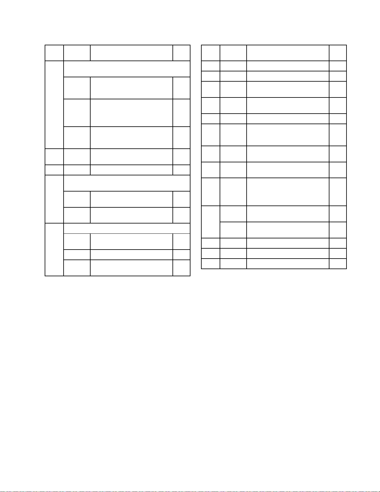
Parts
Part
No.
Ref.
Ref. Ref.
No.
No. No.
26
2724N740
28*
29
30
Part Part
SeeESOn-OffandFluidAdjustmentValve,
page71
24N630
26A160
24N632
25N921
SeeAtomizingAirRestrictorValveAssembly,
page73
24T304
24N733
SeeFanAirAdjustmentValveAssembly,page72
24N634
24N732
25N919
Description
No. No.
Description Description
VALVE,ESOn/OffandFluid
AdjustmentValve;forall
modelsexceptasnoted
VALVE,ESOn-OffwithAir
RestrictorandFluidAdjustment
Valve;forHighAirFlowgun
models
VALVE,ESOn-OffandFixed
FluidValve;forFixedFluid
Flowmodels
SCREW,hexsocket;sst;
packageof2
GASKET,barrel
VALVE,airrestrictor;forall
otherguns
VALVE,airrestrictor;for
L60T11
VALVE,fanair;forallother
guns
VALVE,fanair;forL60T11
VALVE,fanair;quickadjust
withspringreturn
Qty
Qty Qty
1
1
1
1
1
1
1
1
1
1
Ref.
Ref. Ref.
No.
No. No.
34185116
35*
36185103
40107460
41276741
4224N786
43110231
44116553
45117824
46
47▲179791
48▲16P802
5024N783
Part
No.
Part Part
188749
24N603
24N604
Description
No. No.
Description Description
SPRING,compression
PACKING,u-cup
TUBE,exhaust;1/4in.(6mm)
ID(shippedloose)
TOOL,wrench,ballend;4mm
(shippedloose)
MULTI-TOOL(shippedloose)
PLUG,restrictor(shipped
loose;foruseinsteadofitem
29)
CLAMP,exhausttube(shipped
loose)
GREASE,dielectric;1oz(30
ml)tube(notshown)
GLOVE,conductive,medium;
packageof12;alsoavailable
insmall(117823)andlarge
(117825)
COVER,gun,40and60kV
guns;packageof10
COVER,gun,85kVguns;
packageof10
TAG,warning(notshown)
SIGN,warning(notshown)
HOOK;includesscrew
Qty
Qty Qty
1
1
1
1
1
1
1
1
1
1
1
1
1
1
▲ReplacementDangerandWarninglabels,tags,and
cardsareavailableatnocost.
*ThesepartsareincludedinAirSealRepairKit24N789
(purchaseseparately).
‡ThesepartsareincludedinFluidSealRepairKit24N790
(purchaseseparately).
■Gunbodies(Ref.1)includethebarrelgasket(Ref.28).
NOTE:
NOTE: NOTE:
ferrules(7★)and(8★)arepartofthetoptting(9).
On40kVguns,theo–ring(10★)isnotused,and
3A2494P65
Page 66

Parts
1
Gun
Gun Gun
Models
Models Models
with
Smart
with with
Smart Smart
Display
Display Display
Torqueto20in-lb(2N•m).
663A2494P
Page 67

Gun
Models
Gun Gun
Models Models
with
Smart
with with
Smart Smart
Display
Display Display
Toidentifycomponents,seeModels,page3.
Part
No.
Ref.
Part Part
Ref. Ref.
No.
No. No.
24N665
1■
24N666
24N667
24N668
2
SeePackingRodAssembly,page69
3
SeeElectrodeSelectionChart,page88
24N651
24N704
4
NOZZLE;includes4aand4b.See
FluidNozzleSelectionChart,page79.
4a24N645
4b111507
5
AIRCAP;seeAirCapSelectionGuide,page82
624N644
198307
6a*
7‡
111286
8‡111285FERRULE,back2
24N656
9
24N657
24N658
25N852
25N851
10102982
24N659
11
24N660
24N661
11a24N979
1224N663
1324A445
Description
No. No.
Description Description
BODY,gun;40kVgun
BODY,gun;60kVgun
BODY,gun;85kVgun
BODY,gun;40kVboostergun
ELECTRODE,standard
ELECTRODE,highwear
O-RING,conductive
O-RING;uoroelastomer
RING,retainer;includes6a
PACKING,u-cup;UHMWPE
FERRULE,front
FITTING,uid;40kVgun
FITTING,uid;60kVgun
FITTING,uid;85kVgun
FITTING,uid;60kVgun,HC
uidtube
FITTING,uid;85kVgun,HC
uidtube
PACKING,o-ring
POWERSUPPLY,40kVgun
POWERSUPPLY,60kVgun
POWERSUPPLY,85kVgun
SPRING
TRIGGER;includesitem13
SCREW,trigger;packageof2
Parts
Part
No.
Qty
Qty Qty
1
1
1
1
1
1
1
1
1
1
1
2
1
1
1
1
1
1
1
1
1
1
1
1
Ref.
Part Part
Ref. Ref.
No.
No. No.
14
SeeHighConductivityFluidTubeAssembly:60
kVand85kV,page78
24N695
24N696
24N697
25N844
25N843
25N842
1524N664
25N850HANDLE,smart;40kVgun1
16
24N754HANDLE,smart;60kVgun1
24N755HANDLE,smart;85kVgun1
17185111
18197624
19249323VALVE,exhaust1
112085
19a*
2024N741
2124N626
2224N698NUT1
2324N633VALVE,air1
276733
23a*
24245265
24N630
26
26A160
2724N740
Description
No. No.
Description Description
TUBE,uid,STD;40kVgun
TUBE,uid,STD,withsleeve;
60kVgun
TUBE,uid,STD,withsleeve;
85kVgun
TUBE,uid;HC,40kVgunwith
cover;includes7,8,9,10,22;
seeHighConductivityFluid
TubeAssembly:60kVand85
kV,page78.
TUBE,uid;HC,60kVgunwith
cover;includes7,8,9,10,22;
seeHighConductivityFluid
TubeAssembly:60kVand85
kV,page78.
TUBE,uid;HC,85kVgunwith
cover;includes7,8,9,10,22;
seeHighConductivityFluid
TubeAssembly:60kVand85
kV,page78.
See
AlternatorAssembly,page70
SPRING,compression
SPRING,compression
O-RING
BRACKET
SWIVEL,airinlet;M12x1/4
npsm(m);left-handthread
SEAL,airvalve
CIRCUIT,exible
SeeESOn-OffandFluid
AdjustmentValve,page71
SeeESOn-OffandFluid
AdjustmentValve,page71
SCREW,hexsocket;sst;
packageof2
Qty
Qty Qty
1
1
1
1
1
1
1
1
1
1
1
1
1
1
1
1
1
3A2494P67
Page 68

Parts
Part
No.
Ref.
Part Part
Ref. Ref.
No.
No. No.
25N921
28*
2924T304
3024N634
3124N756
34185116
188749
35*
36185103
40107460
41276741
4224N786
Description
No. No.
Description Description
GASKET,barrel
SeeAtomizingAirRestrictor
ValveAssembly,page73
SeeFanAirAdjustmentValve
Assembly,page72
SeeSmartModuleAssembly,
page74
SPRING,compression
PACKING,u-cup
TUBE,exhaust;1/4in.(6mm)
ID(shippedloose)
TOOL,wrench,ballend;4mm
(shippedloose)
MULTI-TOOL(shippedloose)
PLUG,restrictor(shipped
loose;foruseinsteadofitem
29)
Qty
Qty Qty
1
1
1
1
1
1
1
1
1
1
Ref.
Ref. Ref.
No.
No. No.
43110231
44116553
45117824
46
47▲179791
48▲16P802
5024N783
Part
No.
Part Part
24N603
24N604
Description
No. No.
Description Description
CLAMP,exhausttube
GREASE,dielectric;1oz(30
ml)tube(notshown)
GLOVE,conductive,medium;
packageof12;alsoavailable
insmall(117823)andlarge
(117825)
COVER,gun,60kVguns;
packageof10
COVER,gun,85kVguns;
packageof10
TAG,warning(notshown)
SIGN,warning(notshown)
HOOK;includesscrew
Qty
Qty Qty
1
1
1
1
1
1
1
1
▲ReplacementDangerandWarninglabels,tags,and
cardsareavailableatnocost.
*ThesepartsareincludedinAirSealRepairKit24N789
(purchaseseparately).
‡ThesepartsareincludedinFluidSealRepairKit24N790
(purchaseseparately).
■Gunbodies(Ref.1)includethebarrelgasket(Ref.28).
683A2494P
Page 69

Parts
Packing
Packing Packing
Part
No.
Part Part
No. No.
Includesitems2a-2k
Part
No.
Part Part
No. No.
Includesitems2a-2k
Part
No.
Part Part
No. No.
Includesitems2a-2k
Rod
Rod Rod
24N653
24N653 24N653
24N654
24N654 24N654
24N655
24N655 24N655
Assembly
Assembly Assembly
40
kV
Packing
40 40
kV kV
Packing Packing
60
kV
Packing
60 60
kV kV
Packing Packing
85
kV
Packing
85 85
kV kV
Packing Packing
Rod
Assembly
Rod Rod
Assembly Assembly
Rod
Assembly
Rod Rod
Assembly Assembly
Rod
Assembly
Rod Rod
Assembly Assembly
Part
No.
Ref.
Ref. Ref.
No.
No. No.
2a‡111316
2b‡116905
2c‡178409
2d‡178763
2e
Part Part
24N701
24N702
Description
No. No.
Description Description
O-RING
SEAL
PACKING,uid
PACKING,needle
ROD,packing,40kVguns
(includesitems2jand2k)
ROD,packing,60kVguns
Qty
Qty Qty
1
1
1
1
1
1
Ref.
Ref. Ref.
No.
No. No.
2f
2g185495
2h‡186069
2j◆
2k◆
Part
No.
Part Part
197641NUT,packing1
———
———
Description
No. No.
Description Description
HOUSING,packing
SPACER,packing
NUT,triggeradjustment(part
ofitem2e)
NUT,triggeradjustment(part
ofitem2e)
(includesitems2jand2k)
24N703
ROD,packing,85kVguns
1
(includesitems2jand2k)
‡ThesepartsareincludedinFluidSealRepairKit
Partslabeled———arenotavailableseparately.
24N790(purchaseseparately).
◆ThesepartsareincludedinTriggerAdjustmentNut
Kit24N700(purchaseseparately).
3A2494P69
Qty
Qty Qty
1
1
1
1
Page 70

Parts
Alternator
Alternator Alternator
Part
No.
Part Part
No. No.
Assembly
Assembly Assembly
24N664
24N664 24N664
Alternator
Alternator Alternator
Assembly
Assembly Assembly
Ref.
Ref. Ref.
No.
No. No.
15a24N705
15b♦24N706
15c24Y264
15d♦24N707
Part
Part Part
No.
No. No.
Description
Description Description
COIL,alternator
BEARINGKIT(includestwo
bearings,item15dhousing,
item15efan,item15fcap,
andoneitem15hclip)
SHAFTKIT(includesshaft
andmagnet)
HOUSING;includesitem15f
*ThesepartsareincludedinAirSealRepairKit
24N789(purchaseseparately).
♦ThesepartsareincludedinBearingKit24N706
(purchaseseparately).
Qty
Qty Qty
1
1
1
1
Ref.
Ref. Ref.
No.
No. No.
15e♦
15f♦
15g*
15h♦24N709
28♦*
Part
Part Part
No.
No. No.
———
———
110073
25N921
Description
Description Description
FAN;partofitem15b
CAP,housing;partofitem
15d
O-RING
CLIP;packageof5(oneclip
includedwithitem15b)
GASKET,barrel(notshown)
Qty
Qty Qty
1
1
1
1
1
Partslabeled———arenotavailableseparately.
703A2494P
Page 71

Parts
ES
On
Off
and
ES ES
On On
- --Off Off
Part
No.
Part Part
Valve
Valve Valve
Part
Part Part
Fluid
Fluid Fluid
Part
Part Part
24N630
No. No.
24N630 24N630
No.
26A160
No. No.
26A160 26A160
Adjustment
Adjustment Adjustment
No.
24N632
No. No.
24N632 24N632
Fluid
and and
Fluid Fluid
ES
On-Off
ES ES
On-Off On-Off
ES
On-Off
ES ES
On-Off On-Off
Valve
Valve Valve
ES
On-Off
ES ES
On-Off On-Off
Adjustment
Adjustment Adjustment
and
Fluid
and and
with
with with
and
and and
Adjustment
Fluid Fluid
Adjustment Adjustment
Air
Restrictor
Air Air
Restrictor Restrictor
Fixed
Fluid
Fixed Fixed
Fluid Fluid
Valve
Valve Valve
Part
No.
Ref.
Ref. Ref.
No.
No. No.
and
and and
Valve
Valve Valve
26a
26b*
26c
26f
26g
26h24N631PLATE,retaining1
26j
26m*
26p24N740
Part Part
———
15D371
———
24N649
24N650
GC2082SCREW,set,sockethead
24N648
25E767
113746
Description
No. No.
Description Description
HOUSING,valve;blackfor
models24N630and24N632,
blueforrestrictedmodel
26A160
O-RING
PISTON,valve
LEVER,ESon-off;includes
26g;models24N630and
26A160
LEVER,ESon-off;includes
26g;model24N632
KNOB,adjustment,uid,
black;includes26g;model
24N630
KNOB,adjustment,uid;blue;
includes26g;model26A160
O-RING
SCREW,captive;packof2
Qty
Qty Qty
1
2
1
1
1
2
1
1
1
1
*ThesepartsareincludedinAirSealRepairKit
24N789(purchaseseparately).
Partslabeled———arenotavailableseparately.
3A2494P
71
Page 72

Parts
Fan
Air
Fan Fan
Part
Part Part
(shown)
(shown) (shown)
Part
Part Part
(for
large
(for (for
large large
Ref.
Ref. Ref.
No.
No. No.
30a
30b
30c*
30d24N646
*ThesepartsareincludedinAirSealRepairKit24N789
(purchaseseparately).
Partslabeled———arenotavailableseparately.
Adjustment
Air Air
Adjustment Adjustment
No.
24N634
No. No.
24N634 24N634
No.
24N732
No. No.
24N732 24N732
pattern
pattern pattern
Part
Part Part
———
———
———
111504
Fan
Fan Fan
Fan
Fan Fan
round
round round
No.
Description
No. No.
Description Description
NUT,valve1
STEM,valve
STEM,valve;roundsprayonly
O-RING
RING,retaining;packageof6
Valve
Valve Valve
Air
Adjustment
Air Air
Adjustment Adjustment
Air
Adjustment
Air Air
Adjustment Adjustment
spray
guns,
spray spray
guns, guns,
Assembly
Assembly Assembly
Valve
Assembly
Valve Valve
Assembly Assembly
Valve
Assembly
Valve Valve
Assembly Assembly
not
shown)
not not
shown) shown)
Qty
Qty Qty
1
1
1
1
Quick
Quick Quick
Part
Part Part
return
return return
Ref.
Ref. Ref.
No.
No. No.
55a
55b
55c
55d
55e
55f
Adjust
Adjust Adjust
No.
25N919
No. No.
25N919 25N919
.
Part
Part Part
24N650
GC2081
GC2080
25P399
25P398
25P397
Fan
Valve
Fan Fan
Valve Valve
Quick
Adjust
Quick Quick
Adjust Adjust
No.
Description
No. No.
Description Description
LEVER1
SCREW,set
SCREW,set
KIT,leveradapter1
KIT,spring1
KIT,shaftassembly
Fan
Fan Fan
Assembly
Assembly Assembly
Valve
with
Valve Valve
spring
with with
spring spring
Qty
Qty Qty
1
2
1
72
3A2494P
Page 73

Parts
Atomizing
Atomizing Atomizing
Assembly
Assembly Assembly
Part
No.
Part Part
No. No.
Assembly
Assembly Assembly
Part
No.
Part Part
No. No.
Assembly
Assembly Assembly
shown)
shown) shown)
Air
Restrictor
Air Air
Restrictor Restrictor
24T304
24T304 24T304
(shown)
(shown) (shown)
24N733
24N733 24N733
(for
(for (for
Atomizing
Atomizing Atomizing
Atomizing
Atomizing Atomizing
large
pattern
large large
pattern pattern
round
round round
Valve
Valve Valve
Air
Restrictor
Air Air
Restrictor Restrictor
Air
Restrictor
Air Air
Restrictor Restrictor
spray
spray spray
Valve
Valve Valve
Valve
Valve Valve
guns,
not
guns, guns,
not not
Ref.
Ref. Ref.
No.
No. No.
29a
29b
29c*
29d118907
29e
29f
29g
Part
Part Part
———
———
———
111516
———
———
———
No.
Description
No. No.
Description Description
HOUSING,valve
BODY,valve
BODY,valve;roundsprayonly
O-RING
RING,retaining
STEM,valve
KNOB,shaft;roundsprayonly
SETSCREW,knob;round
sprayonly
Qty
Qty Qty
1
1
1
1
1
1
1
1
*ThesepartsareincludedinAirSealRepairKit
24N789(purchaseseparately).
Partslabeled———arenotavailableseparately.
3A2494P73
Page 74

Parts
Smart
Smart Smart
Part
Part Part
Module
Module Module
No.
24N756
No. No.
24N756 24N756
Assembly
Assembly Assembly
Smart
Module
Smart Smart
Module Module
Assembly
Assembly Assembly
Ref.
Ref. Ref.
No.
No. No.
31a
31b24P433
31c24N787
31d♦
31e♦
31f
Part
Part Part
———
———
———
112319
No.
Description
No. No.
Description Description
CARTRIDGE
GASKET
SWITCH,ESHI/LO
SCREW
SCREW,pivot
O-RING
Qty
Qty Qty
1
1
1
3
1
1
Partslabeled———arenotavailableseparately.
♦ThesepartsareincludedinSmartModuleScrew
Kit24N757(purchaseseparately).
74
3A2494P
Page 75

Parts
Round
Round Round
Part
Part Part
NOTE:
NOTE: NOTE:
Spray
Spray Spray
No.
24N318
No. No.
24N318 24N318
Assembly
Assembly Assembly
large
pattern
large large
pattern pattern
Itemsmarkedwitha★areshownfor
referenceandarenotincludedinthekit.
Part
No.
Ref.
Ref. Ref.
No.
No. No.
424N729
4a24N645
4b111507
5
2924N733
3024N732
4924N730
Part Part
24N731
Description
No. No.
Description Description
NOZZLE,roundspray;includes4aand4b.See
FluidNozzleSelectionChart,
page79.
O-RING,conductive
O-RING;uoroelastomer
AIRCAP,roundspray.See
AirCapSelectionGuide,page
82.
ATOMIZINGAIR
RESTRICTORVALVE,
roundspray
FANAIRADJUSTMENT
VALVE,roundspray
DIFFUSER,roundspray
Qty
Qty Qty
1
1
1
1
1
1
1
3A2494P75
Page 76

Parts
Part
No.
Part Part
Part
Part Part
NOTE:
NOTE: NOTE:
25N836
No. No.
25N836 25N836
No.
25N837
No. No.
25N837 25N837
Itemsmarkedwitha★areshownfor
small
pattern
small small
pattern pattern
medium
medium medium
pattern
pattern pattern
referenceandarenotincludedinthekit.
Part
No.
Ref.
Ref. Ref.
No.
No. No.
3
3c
425N835
4a24N645
4b111507
4c117610
4d111516
5
6
Part Part
25N838
25N839
25N938
25N939
113137
113746
———
———
25N840
25N841
———
Description
No. No.
Description Description
AIRCAP,inner,smallpattern;
includes3a–3c
AIRCAP,inner,medium
pattern;includes3a–3c
DEFLECTOR,smallpattern
DEFLECTOR,mediumpattern
O-RING,smallpattern
O-RING,mediumpattern
DIFFUSER,smallpattern
DIFFUSER,mediumpattern
NOZZLE,roundspray;
includes4a–4d
O-RING,conductive
O-RING;uoroelastomer
O-RING
CONDUCTIVECONTACT
RING
AIRCAP,smallpattern
AIRCAP,mediumpattern
RETAININGRING
Qty
Qty Qty
1
1
1 3a
1
1 3b
1
1
1
1
1
1
1
1
1
1
1
763A2494P
Page 77

Parts
High
High High
Part
Part Part
Part
Part Part
Conductivity
Conductivity Conductivity
No.
25N844
No. No.
25N844 25N844
No.
25N937
No. No.
25N937 25N937
40
40 40
40
40 40
Fluid
Fluid Fluid
kV
High
kV kV
High High
kV
High
kV kV
High High
Tube
Tube Tube
Conductivity
Conductivity Conductivity
Conductivity
Conductivity Conductivity
Assembly:
Assembly: Assembly:
Fluid
Tube
Fluid Fluid
Tube Tube
Fluid
Tube
Fluid Fluid
Tube Tube
40
kV
40 40
kV kV
Assembly,
Assembly, Assembly,
Assembly,
Assembly, Assembly,
Ref.
Ref. Ref.
No.
No. No.
7
8111286FERRULE1
924N656
14
2224N656NUT1
CP
CA
Partslabeled———arenotavailableseparately.
*Highconductivitygunmodelsincludeahigh
conductivityuidtubeassemblywithacover.High
conductivityuidtubeassemblieswithnocoverare
availableasanaccessoryonly.
with
cover
with with
cover cover
no
cover
no no
cover cover
Part
No.
Part Part
111285FERULE1
–——
–——
25N943
Description
No. No.
Description Description
FITTING,Fluid;40kV
CoilFluidTube
CAP;includedincoverkit
25N943
Cover,40kVHCuidtube
Qty
Qty Qty
1
1
1
1
3A2494P
77
Page 78

Parts
High
High High
Part
Part Part
Part
Part Part
Part
Part Part
Part
Part Part
Conductivity
Conductivity Conductivity
No.
25N843
No. No.
25N843 25N843
No.
25N842
No. No.
25N842 25N842
No.
25N936
No. No.
25N936 25N936
No.
25N935
No. No.
25N935 25N935
60
60 60
85
85 85
60
60 60
85
85 85
Fluid
Fluid Fluid
kV
High
kV kV
High High
kV
High
kV kV
High High
kV
High
kV kV
High High
kV
High
kV kV
High High
Tube
Tube Tube
Conductivity
Conductivity Conductivity
Conductivity
Conductivity Conductivity
Conductivity
Conductivity Conductivity
Conductivity
Conductivity Conductivity
Assembly:
Assembly: Assembly:
Fluid
Tube
Fluid Fluid
Tube Tube
Fluid
Tube
Fluid Fluid
Tube Tube
Fluid
Tube
Fluid Fluid
Tube Tube
Fluid
Tube
Fluid Fluid
Tube Tube
60
kV
and
85
60 60
kV kV
and and
Assembly,
Assembly, Assembly,
Assembly,
Assembly, Assembly,
Assembly,
Assembly, Assembly,
Assembly,
Assembly, Assembly,
with
cover
with with
cover cover
with
cover
with with
cover cover
no
cover
no no
cover cover
no
cover
no no
cover cover
Ref.
Ref. Ref.
No.
No. No.
7
8111286FERRULE2
9
10102982
14
2224N698NUT1
CP
CA*
Part
Part Part
No.
No. No.
111285FERRULE2
25N852
25N851
———
———
COVER
25N942
25N941
kV
85 85
kV kV
Description
Description Description
FITTING,uid;60kV(shown)
FITTING,uid;85kV
O-RING
COILEDFLUIDTUBE
CAP;includedincoverkits
25N941and25N942
Cover,60kVHCuidtube
(25N843)
Cover,85kVHCuidtube
(25N842)
Qty
Qty Qty
1
1
1
1
1
1
1
Partslabeled———arenotavailableseparately.
*Highconductivitygunmodelsincludeahigh
conductivityuidtubeassemblywithacover.High
conductivityuidtubeassemblieswithnocoverare
availableasanaccessoryonly.
783A2494P
Page 79

FluidNozzles
Fluid
Fluid Fluid
Fluid
Fluid Fluid
Toreducetheriskofaninjury,followthePressureReliefProcedure,page36,beforeremovingorinstalling
auidnozzleand/oraircap.
Fluid
Fluid Fluid
Part
Part Part
24N619
24N613
25N895
25N896
24N616
25N897
24N618
Nozzles
Nozzles Nozzles
Nozzle
Nozzle Nozzle
Nozzle
Nozzle Nozzle
No.
No. No.
Selection
Selection Selection
Orice
Orice Orice
mm
mm mm
0.55(.022)
0.75(.029)
1.0(.042)Green
1.2(.047)Gray
1.5(.055)
1.8(.070)
2.0(.079)
Size
Size Size
(in.)
(in.) (in.)
Chart
Chart Chart
Color
Color Color
Black
Black
Black
Brown
Black
Description
Description Description
Standard
Standard Standard
forstandardcoatings
nozzles
nozzles nozzles
(STD)
(STD) (STD)
25N831
25N832
25N833
25N834
24N620
24N621
24N622
24N623
24N624
24N625
24N729
25N835
1.0(.042)Green
1.2(.047)Gray
1.5(.055)
1.8(.070)
0.75(.029)
1.0(.042)
1.2(.047)
1.5(.055)
1.8(.070)
2.0(.079)
———
———
Precision
Precision Precision
Black
Brown
Blue
Black
Black
withhardenedSSTseatanddamageresistantSSTtip;for
standardcoatings,abrasives,andmetallics
High
High High
withhardenedceramicseat,forabrasivesandmetallics
Round
Round Round
forusewithlargepatternroundsprayaircaponly
Round
Round Round
forusewithmediumorsmallpatternroundsprayaircapsonly
high
wear
high high
wear
nozzles
wear wear
nozzles nozzles
spray
large
spray spray
large large
Spray
Spray Spray
nozzles
wear wear
nozzles nozzles
(HW)
(HW) (HW)
pattern
pattern pattern
medium
medium medium
(PHW)
(PHW) (PHW)
nozzle
nozzle nozzle
small
or ororsmall small
pattern
pattern pattern
nozzle
nozzle nozzle
3A2494P79
Page 80

FluidNozzles
5
0.5
1.0
1.5
2.0
2.5
3.0
0 1 2
60 120 180 240 300
3 4 5 6 7 8 9 10
10
15
20
25
30
35
40
45
50
Fluid
Fluid Fluid
Nozzle
Nozzle Nozzle
Performance
Performance Performance
Charts
Charts Charts
Usethefollowingproceduretoselecttheproperuidnozzleforyourapplication.
1.Foreachuidnozzlechart,ndthepointonthe
graphcorrespondingtoyourdesiredowrate
andviscosity.Markthepointoneachgraphwith
apencil.
2.Thethickverticallineineachgraphrepresents
thetargetowrateforthatnozzlesize.Find
thegraphthathasthemarkedpointclosestto
thethickverticalline.Thisistherecommended
nozzlesizeforyourapplication.Signicantly
exceedingthetargetowratemayresultin
lowersprayperformanceduetoexcessiveuid
velocity.
Key
Key Key
NOTE:
NOTE: NOTE:
Fluid
to totoFluid Fluid
Nozzle
Nozzle Nozzle
Performance
Performance Performance
Charts
Charts Charts
Fluidpressuresaremeasuredatthesprayguninlet.
260CentipoiseFluid
160CentipoiseFluid
70CentipoiseFluid
20CentipoiseFluid
3.Fromthemarkedpoint,moveacrosstothe
verticalscaletondtherequireduidpressure.
Iftherequiredpressureistoohigh,usethenext
largestnozzlesize.Iftheuidpressureistoolow
(<0.35bar,3.5kPa,5psi),usethenextsmallest
nozzlesize.
Table
10
Table Table
FLUID
FLUID FLUID
PRES-
PRES- PRESSURE:
SURE: SURE:
bar,
psi
803A2494P
Orice
10 10
. ..Orice Orice
Size:
0.55
mm
Size: Size:
0.55 0.55
FLUID
FLUID FLUID
oz/min,cc/min
(0.022
mm mm
(0.022 (0.022
FLOW:
FLOW: FLOW:
in.)
in.) in.)
Table
11
Table Table
FLUID
FLUID FLUID
PRES-
PRES- PRESSURE:
SURE: SURE:
bar,
psi
Orice
11 11
. ..Orice Orice
Size:
0.75
mm
Size: Size:
0.75 0.75
FLUID
FLUID FLUID
oz/min,cc/min
(0.030
mm mm
(0.030 (0.030
FLOW:
FLOW: FLOW:
in.)
in.) in.)
Page 81

FluidNozzles
Table
12
Table Table
FLUID
FLUID FLUID
PRES-
PRES- PRESSURE:
SURE: SURE:
bar,
psi
Table
Table Table
Orice
12 12
. ..Orice Orice
13
Orice
13 13
. ..Orice Orice
Size:
1.0
mm
Size: Size:
1.0 1.0
FLUID
FLUID FLUID
oz/min,cc/min
Size:
1.2
Size: Size:
1.2 1.2
(0.040
mm mm
(0.040 (0.040
FLOW:
FLOW: FLOW:
mm
(0.047
mm mm
(0.047 (0.047
in.)
in.) in.)
in.)
in.) in.)
Table
15
Table Table
FLUID
FLUID FLUID
PRES-
PRES- PRESSURE:
SURE: SURE:
bar,
psi
Table
Table Table
Orice
15 15
. ..Orice Orice
16
Orice
16 16
. ..Orice Orice
Size:
1.8
mm
Size: Size:
1.8 1.8
FLUID
FLUID FLUID
oz/min,cc/min
Size:
2.0
Size: Size:
2.0 2.0
(0.070
mm mm
(0.070 (0.070
FLOW:
FLOW: FLOW:
mm
(0.080
mm mm
(0.080 (0.080
in.)
in.) in.)
in.)
in.) in.)
FLUID
FLUID FLUID
PRES-
FLUID
FLUID FLUID
PRES-
PRES- PRESSURE:
SURE: SURE:
bar,
psi
FLUID
FLOW:
FLUID FLUID
FLOW: FLOW:
oz/min,cc/min
Table
14
Table Table
FLUID
FLUID FLUID
PRES-
PRES- PRESSURE:
SURE: SURE:
bar,
psi
Orice
14 14
. ..Orice Orice
Size:
1.5
mm
Size: Size:
1.5 1.5
(0.059
mm mm
(0.059 (0.059
in.)
in.) in.)
PRES- PRESSURE:
SURE: SURE:
bar,
psi
FLUID
FLOW:
FLUID FLUID
FLOW: FLOW:
oz/min,cc/min
FLUID
FLOW:
FLUID FLUID
FLOW: FLOW:
oz/min,cc/min
3A2494P81
Page 82

AirCaps
Air
Air Air
Air
Air Air
Thechartsinthissectioncanassistyouinselecting
anaircap.
•Keepinmindthatmorethanoneaircapcanmeet
•Whenselectinganaircap,considercoating
Caps
Caps Caps
Cap
Cap Cap
Toreducetheriskofaninjury,followthe
PressureReliefProcedure,page36,before
removingorinstallingauidnozzleand/oraircap.
yournishrequirements.
properties,partgeometry,patternshape,pattern
size,andoperatorpreferences.
Selection
Selection Selection
Guide
Guide Guide
Measurements
Measurements Measurements
Allaircappatternshapesandlengthsinthefollowing
chartsweremeasuredunderthefollowingconditions,
unlessotherwisenoted:
NOTE:
NOTE: NOTE:
material-dependent.
•Distancetotarget:10in.(254mm)
•Inletairpressure:50psi(34kPa,3.4bar)
•Fanair:adjustedformaximumlength
•Fluidowrate:10oz/min(300cc/min)
Patternshapeandlengthare
823A2494P
Page 83

AirCaps
Pattern
Pattern Pattern
NOTE:Patternshapesareinuencedbythematerialviscosity,owrate,andairpressuresettings.Thegun
maynotmaintaintheintendeddesignshapeunderallconditions.
•Round Round
•Fan Fan
Shape
Shape Shape
Round
Fan
–Fan Fan
patterns
patterns patterns
patterns
patterns patterns
Fan
patterns
patterns patterns
optionforsmallerpartsorcut-inpainting.
haveaswirling,slow,roundconepatternforexcellentnishandtransferefciency.
havetwostyles:roundendsandtaperedends.
with
with with
round
ends
round round
ends ends
areversatile.Theycanbeusedinanyapplicationandareoftenthebest
Fan
–Fan Fan
patterns
patterns patterns
passes.
with
tapered
with with
tapered tapered
ends
ends ends
arebestforachievingevencoatingthicknesswithoverlappingpaint
3A2494P83
Page 84

AirCaps
General
General General
Part
Part Part
24N477Black
24W279
24N438BlackAlternate
24N376Black
24N276Blue
24N277Red
24N278
24N274Black
General
General General
Part
Part Part
24N477Black
24W279
24N438BlackAlternateRound
24N376Black
24N276Blue
24N277Red
24N278
24N274Black
Fan
Pattern
Fan Fan
Pattern Pattern
No.
Color
No. No.
Color Color
Green
Green
Fan
Pattern
Fan Fan
Pattern Pattern
No.
Color
No. No.
Color Color
Green
Green
Air
Caps:
Air Air
Caps: Caps:
Description
Description Description
StandardMostversatileaircap.Recommendedformostmaterialsandapplications.Class
LongPattern
ShortPatternShorterpattern,optimizedforpaintingwithoverlappingpasses.
Air
Caps:
Air Air
Caps: Caps:
Description
Description Description
Standard
LongPatternTapered
ShortPattern
Descriptions
Descriptions Descriptions
Guidelines
Guidelines Guidelines
Anish.
Similartothestandardaircapwithanalternatearrangementofatomizingair.
Longestspraypattern,optimizedforpaintinglargepartswithoverlappingpaint
passes.
Specications
Specications Specications
Pattern
Pattern Pattern
Shape
Shape Shape
Round
end
end
end
Tapered
end
for
Use
for for
Use Use
Nominal
Nominal Nominal
Pattern
Pattern Pattern
Length
Length Length
in.
(mm)
in. in.
(mm) (mm)
15-17
(381-432)
15-17
(381-432)
17-19
(432-483)
12-14
(305-356)
Recommended
Recommended Recommended
Fluid
Viscosity*
Fluid Fluid
Viscosity* Viscosity*
Lighttomedium
Lighttomedium
Lighttomedium
Lighttomedium
Recommended
Recommended Recommended
Production
Production Production
Rates**
Rates** Rates**
Standard
Standard
Standard
StandardGood
Atom-
Atom- Atomization
ization ization
Best
Best
BetterBetter
Clean-
Clean- Cleanliness
liness liness
Good
Good
Best
*FluidViscosity,incentipoise(cp)at70°F(21°C).
Centipoise=centistokesxuidspecicgravity.
Lighttomedium20–70cp
Mediumtoheavy70–360cpLow
Highsolids360+cpHigh
**RecommendedProductionRates
Standard300cc/minto500cc/min(10oz/min
VeryHigh
to17oz/min)
100cc/minto300cc/min(3oz/min
to10oz/min)
500cc/minto600cc/min(17oz/min
to20oz/min)
600cc/minto750cc/min(20oz/min
to25oz/min)
843A2494P
Page 85

AirCaps
Specialty
Specialty Specialty
Part
Part Part
25E670Black
24N275BlackAerospace
24N279Black
24N439Black
25E671BlackHVLPForapplicationswhereHVLPisrequired.
Specialty
Specialty Specialty
Part
Part Part
25E670Black
24N275BlackAerospaceTapered
24N279Black
24N439Black
25E671BlackHVLPRound
Fan
Pattern
Fan Fan
Pattern Pattern
No.
Color
No. No.
Color Color
Fan
Pattern
Fan Fan
Pattern Pattern
No.
Color
No. No.
Color Color
Air
Caps:
Air Air
Description
Description Description
SoftSprayForpaintingsmall,lightweightpartswithaslow-movingspraypattern.Optimized
SolidsOptimizedformediumandheavyviscosityandhighsolidcoatingsatstandard
SolidsHigh
Flow
Air
Air Air
Description
Description Description
SoftSpray
Solids
SolidsHigh
Flow
Descriptions
Caps: Caps:
Descriptions Descriptions
Guidelines
Guidelines Guidelines
forlowproductionrates.
Optimizedforaerospacecoatings.
•ClassAnish
•Light,medium,andheavyviscosity,andhighsolidcoatings
•Veryhighproductionrates
productionrates.
Requiredforusewith2.0mmnozzles.Optimizedformediumandheavyviscosity
andhighsolidcoatingsathighproductionrates.
Caps:
Specications
Caps: Caps:
Specications Specications
Pattern
Pattern Pattern
Shape
Shape Shape
Round
end
end
Round
end
Tapered
end
end
for
Use
for for
Use Use
Nominal
Nominal Nominal
Pattern
Pattern Pattern
Length
Length Length
in.
(mm)
in. in.
(mm) (mm)
10-12
(254-
305)***
14-16
(356-406)
14-16
(356-406)
11-13
(279-330)
11-13
(279-330)
Recommended
Recommended Recommended
Viscosity*
Viscosity* Viscosity*
LighttomediumLowBetter
Light,medium,and
heavyviscosity,and
highsolids
Mediumtoheavy
viscosityandhigh
solids
Mediumtoheavy
viscosityandhigh
solids
Lighttomedium
Fluid
Fluid Fluid
Recommended
Recommended Recommended
Production
Production Production
Rates**
Rates** Rates**
VeryHigh
Standard
HighBestBetter
StandardGoodGood
Atom-
Atom- Atom-
iza-
iza- iza-
tion
tion tion
Good
Better
Clean-
Clean- Cleanliness
liness liness
Good
Best
Good
*FluidViscosity,incentipoise(cp)at70°F(21°C).
Centipoise=centistokesxuidspecicgravity.
Lighttomedium20–70cp
Mediumtoheavy70–360cpLow
Highsolids360+cpHigh
***Thesoftsprayaircapwasmeasuredwiththeuidowrateadjustedto3.5oz/min(100cc/min).
**RecommendedProductionRates
Standard300cc/minto500cc/min(10oz/min
VeryHigh
to17oz/min)
100cc/minto300cc/min(3oz/min
to10oz/min)
500cc/minto600cc/min(17oz/min
to20oz/min)
600cc/minto750cc/min(20oz/min
to25oz/min)
3A2494P85
Page 86

AirCaps
Round
Round Round
Round
Round Round
Pattern
Pattern Pattern
Part
No.
Part Part
No. No.
24N318BlackLarge
25N837BlackMedium
25N836Black
Pattern
Pattern Pattern
Part
No.
Part Part
No. No.
24N318BlackLargePatternRound
25N837BlackMedium
25N836Black
*FluidViscosity,incentipoise(cp)at70°F(21°C).
Centipoise=centistokesxuidspecicgravity.
Lighttomedium20–70cp
Mediumtoheavy70–360cpLow
Highsolids360+cpHigh
Air
Caps:
Air Air
Caps: Caps:
Color
Color Color
Air
Caps:
Air Air
Caps: Caps:
Color
Color Color
Descriptions
Descriptions Descriptions
Description
Description Description
Pattern
Pattern
Small
Pattern
Specications
Specications Specications
Description
Description Description
Pattern
SmallPattern
Guidelines
Guidelines Guidelines
Conventionalroundpatterndesignforlargerpatternsupto8in(20cm).Swirling,
slow,roundconepatternforexcellentnishandtransferefciency.
Dualinnerandouteratomizingairdesignforimprovedatomizationatlowairows.
Formediumpatternsupto6inches(15cm).Swirling,slow,roundconepatternfor
excellentnishandtransferefciency.
Dualinnerandouteratomizingairdesignforimprovedatomizationatlowairows.
Forsmallpatternsupto4inches(10cm).Swirling,slow,roundconepatternfor
excellentnishandtransferefciency.
Pattern
Pattern Pattern
Shape
Shape Shape
end
Round
end
Round
end
for
Use
for for
Use Use
Nominal
Nominal Nominal
Pattern
Pattern Pattern
Diameter
Diameter Diameter
in.
(mm)
in. in.
(mm) (mm)
8(203)
6(152)
4(102)
Recommended
Recommended Recommended
Viscosity*
Viscosity* Viscosity*
LighttomediumLow
LighttomediumLowBetter
LighttomediumLowBetter
**RecommendedProductionRates
Standard300cc/minto500cc/min(10oz/min
VeryHigh
Fluid
Fluid Fluid
Recommended
Recommended Recommended
Production
Production Production
Rates**
Rates** Rates**
to17oz/min)
100cc/minto300cc/min(3oz/min
to10oz/min)
500cc/minto600cc/min(17oz/min
to20oz/min)
600cc/minto750cc/min(20oz/min
to25oz/min)
Atom-
Atom- Atom-
iza-
iza- iza-
tion
tion tion
GoodGood
Clean-
Clean- Cleanliness
liness liness
Good
Good
863A2494P
Page 87
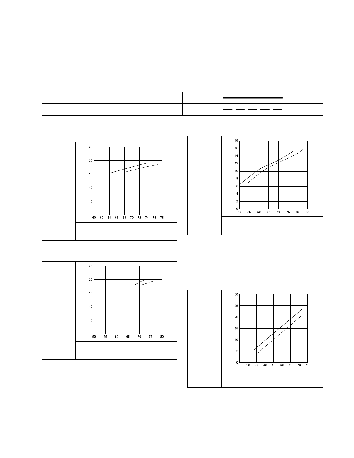
AirCaps
60
0
5
10
15
20
25
62 64 66 68 70 72 74 76 78
50 55 60 65 70 75
0
5
10
15
20
25
80
50
2
0
4
6
8
10
12
14
16
18
55 60 65 70 75 80 85
0
0
5
10
15
20
25
30
10 20 30 40 50 60 70 80
Air
Consumption
Air Air
Consumption Consumption
NOTE:
NOTE: NOTE:
Airconsumptionappliestothecompletegun.
Charts
Charts Charts
Key
Key Key
TEST
TEST TEST
Air
Consumption
to totoAir Air
Consumption Consumption
CONDITIONS:
CONDITIONS: CONDITIONS:
Charts
Charts Charts
Fanvalvefullyopen(unlessotherwisenoted),atomizationvalvefullyopen(unless
otherwisenoted),85kvgun,ESon.
5/16in.x25ft(8mmx7.6m)hose
5/16in.x50ft(8mmx15.2m)hose
Table
17
Table Table
24N438
24N438 24N438
AIR
AIR AIR
SUMPTION
SUMPTION SUMPTION
Table
Table Table
24N477,
17 17
. ..24N477, 24N477,
Air
Cap
Air Air
Cap Cap
CON-
CON- CON-
scfm
18
24N274,
18 18
. ..24N274, 24N274,
24W279,
24W279, 24W279,
WALL
WALL WALL
24N275,
24N275, 24N275,
24N279,
24N279, 24N279,
PRESSURE
PRESSURE PRESSURE
psi
and
and and
24N376,
24N376, 24N376,
24N439
24N439 24N439
and
and and
Air
Cap
Air Air
Cap Cap
Table
19
Table Table
AIR
AIR AIR
SUMPTION
SUMPTION SUMPTION
NOTE:
NOTE: NOTE:
25E670
19 19
. ..25E670 25E670
CON-
CON- CON-
scfm
Air
Cap
Air Air
Cap Cap
WALL
PRESSURE
WALL WALL
PRESSURE PRESSURE
psi
25E670:Atomizationvalveopenedoneturnfrom
closeaccordingtosoftspraygunsetup.See
SoftSprayGunSetupProcedure,page28.
AIR
AIR AIR
SUMPTION
SUMPTION SUMPTION
3A2494P87
Table
20
Table Table
CON-
CON- CON-
scfm
AIR
AIR AIR
SUMPTION
SUMPTION SUMPTION
WALL
PRESSURE
WALL WALL
PRESSURE PRESSURE
psi
25E671
20 20
25E671 25E671
CON-
CON- CON-
scfm
Air
Cap
Air Air
Cap Cap
WALL
PRESSURE
WALL WALL
PRESSURE PRESSURE
psi
Page 88

ElectrodeSelectionChart
Electrode
Electrode Electrode
Toreducetheriskofaninjury,followthePressureReliefProcedure,page36,beforeremovingorinstalling
anelectrode.
Electrode
Electrode Electrode
24N651
25N856
Part
Part Part
Selection
Selection Selection
No.
No. No.
Color
Color Color
GrayStandard(STD)Electrodeassemblywithaexible
GrayShort
Chart
Chart Chart
Description
Description Description
Guidelines
Guidelines Guidelines
snap-backwire.
Thestandardwireisresistantto
abrasiveuidwearandalsoresistant
tohandlingdamage.
Electrodeassemblywithashort
snap-backwire.
Theshortwirehasalow-proledesign
thatpositionsthewireclosertotheair
capforconvenience.
Usetheshortwiretoextendwear
lifeoftheelectrodewireinextremely
abrasivematerials.
for
Use
for for
Use Use
24N704Blue
25N857BrownHardenedElectrodeassemblywithahardened
Highwear(HW)
Electrodeassemblywithahardwire.
Thehardwirecanbendanddoesnot
snapbackifitisdamagedbyhandling.
Usethehighwearelectrodetoextend
wearlifeofthewirewithabrasive
materials.
carbidewire.
Thehardenedwireiseasiertobreak
withhandlingthanthestandardor
highwearwires.
Usethehardenedelectrodetoextend
wearlifeofthewirewithextremely
abrasivematerials.
883A2494P
Page 89

RepairKitsandAccessories
Repair
Repair Repair
Repair
Repair Repair
Part
No.
Part Part
No. No.
24N789
24N790
24N706AlternatorBearingRepairKit
Gun
Gun Gun
General
General General
Trigger
Trigger Trigger
Accessories
Accessories Accessories
Part
No.
Part Part
No. No.
111265
116553
24N603
24N604
24N758
and
and and
Part
No.
Part Part
No. No.
24N633PlasticTriggerKit
24P170MetalTriggerKit
24P171FourFingerTriggerKit,toconvert
Kits
Kits Kits
Kits
Kits Kits
Accessories
Accessories Accessories
Description
Description Description
Non-siliconeLubricant,4oz(113g)
DielectricGrease,1oz(30ml)
GunCovers,for40kVand60kV
guns(boxof10)
GunCovers,for85kVguns(boxof
10)
DisplayCovers.KeepsSmartdisplay
clean(packageof5).
Grip
Grip Grip
Description
Description Description
ProXpairspraygunstoafournger
trigger
and
and and
Description
Description Description
AirSealRepairKit
FluidSealRepairKit
Accessories
Accessories Accessories
Accessories Accessories
Accessories
High
Conductivity
High High
Conductivity Conductivity
Part
No.
Part Part
No. No.
25N844
25N843
25N842
25N937
25N936
25N935
Accessories
Accessories Accessories
Description
Description Description
40kVHighConductivityFluidTube
Kit,withcover.Toconverta40kV
gunfromastandarduidtubetoan
HCuidtube.
60kVHighConductivityFluidTube
Kit,withcover.Toconverta60kV
gunfromastandarduidtubetoan
HCuidtube.
85kVHighConductivityFluidTube
Kit,withcover.Toconvertan85kV
gunfromastandarduidtubetoan
HCuidtube.
40kVHighConductivityFluidTube
Kit,nocover
60kVHighConductivityFluidTube
Kit,nocover
85kVHighConductivityFluidTube
Kit,nocover
24N520
24N521
Atomizing
Atomizing Atomizing
Part
No.
Part Part
No. No.
24N636
3A2494P89
ComfortGrip.Snap-ongrip
increaseshandlesizetoreduce
operatorfatigue.Mediumsize.
ComfortGrip.Snap-ongrip
increaseshandlesizetoreduce
operatorfatigue.Largesize.
Air
Valve
Air Air
Accessories
Valve Valve
Accessories Accessories
Description
Description Description
LowProleAtomizingAirRestrictor
Valve(adjustedwithahextool)
Adapter
Adapter Adapter
Part
Part Part
112534
185105
185493
24N642
224754
and
Fitting
and and
Fitting Fitting
No.
No. No.
Accessories
Accessories Accessories
Description
Description Description
AirLineQuickDisconnectFitting
Non-swivelAirInlet;1/4–18npsm(m)
(left-handthread)
AirHoseAdapter;1/4npt(m)x
1/4–18npsm(m)(left-handthread)
BallSwivel,forgunairinlet;1/4
npsm(left-handthread)
Valve,ball1/4npsm(left-hand
thread)
Page 90

RepairKitsandAccessories
ES
On/Off
ES ES
On/Off On/Off
Part
Part Part
26A160
24P634
24N630
24N632
Fan
Fan Fan
Part
Part Part
24N634
24N732
24P172
and
Fluid
and and
No.
No. No.
Air
Adjustment
Air Air
Adjustment Adjustment
No.
No. No.
Adjustment
Fluid Fluid
Adjustment Adjustment
Description
Description Description
ESOn/OffValveRestrictorforhigh
atomizingairapplications.Use
thisaccessoryiftheturbinelight
indicatorisredandyouwantto
maintainahigherapplicationair
pressure.Installthekit,thenadjust
thepressureasneededtoensure
theindicatorremainsgreen.
ESAlwaysONanduidadjustment
valvekit.Whenthisvalveisinstalled,
theelectrostaticsareonanytimeair
pressureissuppliedtothegun.Fluid
adjustmentispossible.Seemanual
3A6840.
ESOn-OffandFluidAdjustment
Valve
ESOn-OffandFixedFluidValve.
Usetoextendelectrodeandnozzle
lifeinapplicationswithabrasive,
metallic,andextremelyabrasive
materials.
Valve
Valve Valve
Description
Description Description
Standardfanairadjustmentvalve
Fanairadjustmentvalveforlarge
patternroundspray
Quickadjustfanvalveforquick
changeoffansize
Valve
Accessories
Valve Valve
Accessories Accessories
Accessories
Accessories Accessories
Inline
Inline Inline
Filter
Filter Filter
60mesh
100mesh
150mesh
200mesh
Operator
Operator Operator
Part
Part Part
117823
117824
117825
Fluid
Fluid Fluid
Part
No.
Part Part
No. No.
915921FilterHousing3/8
Size
Size Size
No.
No. No.
Filter
Filter Filter
npsm(f)x3/8npsm(m)
with100meshlter
238562.
224453Black
238563Black3
238564Black1
238561Black3
238562Black1
25N891Red1
25N892Red3
25N893Yellow1
25N894Yellow3
Accessories
Accessories Accessories
Description
Description Description
ConductiveGloves,boxof12(small)
ConductiveGloves,boxof12
(medium)
ConductiveGloves,boxof12(large)
Kit
Kit Kit
Description
Description Description
Description
Description Description
Accessories
Accessories Accessories
Qty.
Qty. Qty.
1
Filter
Filter Filter
Color
Color Color
Qty.
Qty. Qty.
5
25N919
Round
Round Round
Spray
Spray Spray
Part
No.
Part Part
No. No.
24N318
25N837
25N836
Quickadjustfanvalvewithspring
return.Seemanual3A7005.
Accessories
Accessories Accessories
Description
Description Description
RoundSprayKit,largepattern,to
convertastandardairspraygunto
aroundsprayaircap.Seemanual
3A2498.
RoundSprayKit,mediumpattern,to
convertastandardairspraygunto
aroundsprayaircap.Seemanual
3A6829.
RoundSprayKit,smallpattern,to
convertastandardairspraygunto
aroundsprayaircap.Seemanual
3A6829.
System
System System
Part
Part Part
222011
24N528
24N529
24P312
Accessories
Accessories Accessories
No.
No. No.
Description
Description Description
GroundWireandClamp
GunFlushBoxAdapterfor60kV
and85kVguns.Toconvertexisting
gunushboxestoholdProXpguns.
Seemanual309227.
GunFlushBoxAdapterfor40kV
guns.Toconvertexistinggunush
boxestoholdProXpguns.See
manual309227.
GunWasherKit.Toconvertexisting
gunwasherstocleanProXpguns.
Seemanual308393.
903A2494P
Page 91

RepairKitsandAccessories
Signs
Signs Signs
Part
No.
Part Part
No. No.
Description
Description Description
16P802
16P798
16P799
Test
Test Test
Equipment
Equipment Equipment
Part
No.
Part Part
No. No.
241079Megohmmeter.500Voutput,
722886
722860
245277TestFixture,HighVoltageProbe,
EnglishWarningSign,availableat
nochargefromGraco
EnglishDailyCareSign
EnglishSetupSign
Description
Description Description
0.01–2000megohms.Usefor
groundcontinuityandgunresistance
Not
for
tests.Not Not
locations.
locations. locations.
PaintResistanceMeter.Useforuid
resistivitytest.Seemanual307263.
Not
for
Not Not
PaintProbe.Useforuidresistivity
test.Seemanual307263.Not Not
use
use use
andkVMeter.Usetotestthe
electrostaticvoltageofthegun,and
theconditionofthealternatorand
powersupplywhenbeingserviced.
Seemanual309455.Alsorequires
24R038ConversionKit.
use
for for
use use
hazardous
in ininhazardous hazardous
use
for for
use use
hazardous
in ininhazardous hazardous
hazardous
in ininhazardous hazardous
locations.
locations. locations.
Not
for
for for
locations.
locations. locations.
24R038
25E919
VoltageTesterConversionKit.
Convertsthe245277TestFixturefor
usewiththeProXpGunalternator.
Seemanual406999.
HVLPAirCapVericationKit.Use
toverifyairpressuresinaircaps
inHVLPapplications.Foruse
with25E671aircap.Seemanual
3A6833.
3A2494P91
Page 92

RepairKitsandAccessories
Hoses
Hoses Hoses
Grounded
Grounded Grounded
Air
Hoses
Air Air
Hoses Hoses
100psi(0.7MPa,7bar)MaximumWorkingPressure
0.315in.(8mm)ID;1/4npsm(f)x1/4npsm(f)left-handthread
Part
No.
Part Part
No. No.
AirFlex
AirFlex AirFlex
244963
244964
244965
24J138
24N736
244966
24N737
244967
24N738
244968
244969
Part
Part Part
Standard
Standard Standard
223068
223069
223070
223071
223072
223073
223074
0.375
0.375 0.375
left
left left
24A225
24A226
Flexible
Flexible Flexible
No.
No. No.
Grounded
Grounded Grounded
in.
(10
in. in.
(10 (10
hand
thread
- --hand hand
thread thread
Description
Description Description
Grounded
Grounded Grounded
6ft(1.8m)
15ft(4.6m)
25ft(7.6m)
31ft(9.4m)
25ft(7.6m),with112534Quick
Disconnect
36ft(11m)
36ft(11m),with112534Quick
Disconnect
50ft(15m)
50ft(15m),with112534Quick
Disconnect
75ft(23m)
100ft(30.5m)
Description
Description Description
6ft(1.8m)
15ft(4.6m)
25ft(7.6m)
36ft(11m)
50ft(15m)
75ft(23m)
100ft(30.5m)
mm)
ID;
mm) mm)
ID; ID;
50ft(15m)
75ft(23m)
Air
Air Air
Air
Hose
Air Air
Hose Hose
3/8
npsm(f)
3/8 3/8
npsm(f) npsm(f)
Hose
(Gray)
Hose Hose
(Gray) (Gray)
(Gray)
(Gray) (Gray)
1/4
npsm(f)
x xx1/4 1/4
npsm(f) npsm(f)
Part
No.
Part Part
No. No.
Grounded
Grounded Grounded
ground
ground ground
235068
235069
235070
235071
235072
235073
235074
Air
Air Air
path
path path
Whip
Hoses
Whip Whip
Hoses Hoses
Air
Air Air
Description Description
Hose
Hose Hose
(Red)
(Red) (Red)
6ft(1.8m)
15ft(4.6m)
25ft(7.6m)
36ft(11m)
50ft(15m)
75ft(23m)
100ft(30.5m)
Description
with
stainless
with with
stainless stainless
steel
steel steel
100psi(0.7MPa,7bar)MaximumWorkingPressure
0.188in.(5mm)ID;1/4npsm(m)x1/4npsm(f)
left-handthread
Part
No.
Part Part
No. No.
Air
Whip
Air Air
path
path path
236130
236131
Fluid
Fluid Fluid
Hose
Whip Whip
Hose Hose
(Red)
(Red) (Red)
Hoses
Hoses Hoses
Description
Description Description
with
stainless
with with
stainless stainless
3ft(0.9m)
6ft(1.8m)
steel
braid
steel steel
braid braid
225psi(1.4MPa,14bar)MaximumWorking
Pressure
1/4in.(6mm)ID;3/8npsm(fbe);nylon
Part
No.
Part Part
No. No.
215637
215638
High
Conductivity
High High
Conductivity Conductivity
Forlowresistivity,highviscositymaterials.For For
kV
guns
kV kV
only.
guns guns
only. only.
Description
Description Description
25ft(7.6m)
50ft(15m)
Fluid
Fluid Fluid
Hose
Hose Hose
100psi(0.7MPa,7bar)MaximumWorkingPressure
braid
braid braid
ground
ground ground
For
60
60 60
1/4in.(6mm)ID;3/8npsm(f)x5/8–20(m);PTFE
Part
No.
Part Part
No. No.
24N994
Description
Description Description
26.8ft(8.2m)
923A2494P
Page 93

Dimensions
Dimensions
Dimensions Dimensions
KV
KV KV
40
40
40
40
60
60
60
60
85
85
85
85
SeeModels,page3forgunpartnumbers.
Display
Display Display
StandardStandard8.7(221)9.2(234)2.4(61)19.8(562)
StandardHC8.7(221)9.2(234)2.4(61)20.5(620)
SmartStandard8.7(221)10(254)2.4(61)22.3(632)
SmartHC8.7(221)10(254)2.4(61)24.3(690)
StandardStandard9.5(241)9.2(234)2.4(61)21.1(600)
StandardHC9.5(241)9.2(234)2.4(61)23.3(660)
SmartStandard9.5(241)10(254)2.4(61)23.7(673)
SmartHC9.5(241)10(254)2.4(61)25.9(733)
StandardStandard10.5(267)9.2(234)2.4(61)23.8(676)
StandardHC10.5(267)9.2(234)2.4(61)26.2(743)
SmartStandard10.5(267)10(254)2.4(61)26.3(746)
SmartHC10.5(267)10(254)2.4(61)28.7(813)
Fluid
Fluid Fluid
Tube
Tube Tube
Dimensions
Dimensions Dimensions
A,
in.
(mm)
A, A,
in. in.
(mm) (mm)
B,
in.
(mm)
B, B,
in. in.
(mm) (mm)
C,
in.
(mm)
C, C,
in. in.
(mm) (mm)
Weight,
Weight, Weight,
oz
(g)
oz oz
(g) (g)
3A2494P93
Page 94

TechnicalSpecications
Technical
Technical Technical
Electrostatic
Electrostatic Electrostatic
MaximumWorkingFluidPressure100psi0.7MPa,7.0bar
MaximumWorkingAirPressure100psi0.7MPa,7.0bar
MinimumAirPressureatGunInlet
AirConsumption
Requiredturbineairow6scfm
Rangeoftotalairowunder
normalsprayingconditions
MaximumFluidOperating
Temperature
AmbientTemperature
PaintResistivityRange
AirInletFitting
FluidInletFitting
OutputVoltage
Specications
Specications Specications
Air
Spray
Air Air
Guns
Spray Spray
Guns Guns
170l/min
425–565l/min
Metric
Metric Metric
U.S.
U.S. U.S.
45psi0.32MPa,3.2bar
15–20scfm
120°F48°C
41°–122°F5°–50°C
3megohm/cmtoinnity.Foratableofelectrostaticresultsatdifferent
resistancelevels,seeCheckFluidResistivity,page35.
1/4npsm(m)left-handthread
3/8npsm(m)
ProXp40Models:40kV
ProXp60Models:60kV
ProXp85Models:85kV
MaximumCurrentDraw
SoundPower(measuredperISO
Standard9216)
SoundPressure(measured1m
fromgun)
WettedPartsPEEK,UHMWPE,FEP,PTFE,acetal,nylon,polyeth-
California
California California
CALIFORNIA
CALIFORNIA CALIFORNIA
WARNING:
WARNING: WARNING:
RESIDENTS
RESIDENTS RESIDENTS
Proposition
Proposition Proposition
Cancerandreproductiveharm—www.P65warnings.ca.gov.
at40psi:90.4dB(A)
at100psi:105.4dB(A)
at40psi:87.0dB(A)
at100psi:99.0dB(A)
65
65 65
125microamperes
at0.28MPa,2.8bar:90.4dB(A)
at0.7MPa,7.0bar:105.4dB(A)
at0.28MPa,2.8bar:87.0dB(A)
at0.7MPa,7.0bar:99.0dB(A)
ylene,stainlesssteel
943A2494P
Page 95

Graco
Graco Graco
GracowarrantsallequipmentreferencedinthisdocumentwhichismanufacturedbyGracoandbearingitsname
tobefreefromdefectsinmaterialandworkmanshiponthedateofsaletotheoriginalpurchaserforuse.Withthe
exceptionofanyspecial,extended,orlimitedwarrantypublishedbyGraco,Gracowill,foraperiodoftwelvemonths
fromthedateofsale,repairorreplaceanypartoftheequipmentdeterminedbyGracotobedefective.However,any
deciencyinthebarrel,handle,trigger,hook,internalpowersupply,andalternator(excludingturbinebearings)willbe
repairedorreplacedforthirty-sixmonthsfromthedateofsale.Thiswarrantyappliesonlywhentheequipmentis
installed,operatedandmaintainedinaccordancewithGraco’swrittenrecommendations.
Thiswarrantydoesnotcover,andGracoshallnotbeliableforgeneralwearandtear,oranymalfunction,damage
orwearcausedbyfaultyinstallation,misapplication,abrasion,corrosion,inadequateorimpropermaintenance,
negligence,accident,tampering,orsubstitutionofnon-Gracocomponentparts.NorshallGracobeliablefor
malfunction,damageorwearcausedbytheincompatibilityofGracoequipmentwithstructures,accessories,
equipmentormaterialsnotsuppliedbyGraco,ortheimproperdesign,manufacture,installation,operationor
maintenanceofstructures,accessories,equipmentormaterialsnotsuppliedbyGraco.
Thiswarrantyisconditionedupontheprepaidreturnoftheequipmentclaimedtobedefectivetoanauthorized
Gracodistributorforvericationoftheclaimeddefect.Iftheclaimeddefectisveried,Gracowillrepairorreplace
freeofchargeanydefectiveparts.Theequipmentwillbereturnedtotheoriginalpurchasertransportationprepaid.
Ifinspectionoftheequipmentdoesnotdiscloseanydefectinmaterialorworkmanship,repairswillbemadeata
reasonablecharge,whichchargesmayincludethecostsofparts,labor,andtransportation.
THIS
WARRANTY
THIS THIS
WARRANTY WARRANTY
INCLUDING
INCLUDING INCLUDING
PARTICULAR
PARTICULAR PARTICULAR
Graco’ssoleobligationandbuyer’ssoleremedyforanybreachofwarrantyshallbeassetforthabove.Thebuyer
agreesthatnootherremedy(including,butnotlimitedto,incidentalorconsequentialdamagesforlostprots,lost
sales,injurytopersonorproperty,oranyotherincidentalorconsequentialloss)shallbeavailable.Anyactionfor
breachofwarrantymustbebroughtwithintwo(2)yearsofthedateofsale.
GRACO
GRACO GRACO
FITNESS
FITNESS FITNESS
OR
OR OR
Graco(suchaselectricmotors,switches,hose,etc.),aresubjecttothewarranty,ifany,oftheirmanufacturer.Graco
willprovidepurchaserwithreasonableassistanceinmakinganyclaimforbreachofthesewarranties.
InnoeventwillGracobeliableforindirect,incidental,specialorconsequentialdamagesresultingfromGraco
supplyingequipmenthereunder,orthefurnishing,performance,oruseofanyproductsorothergoodssoldhereto,
whetherduetoabreachofcontract,breachofwarranty,thenegligenceofGraco,orotherwise.
FORGRACOCANADACUSTOMERS
ThePartiesacknowledgethattheyhaverequiredthatthepresentdocument,aswellasalldocuments,noticesand
legalproceedingsenteredinto,givenorinstitutedpursuantheretoorrelatingdirectlyorindirectlyhereto,bedrawn
upinEnglish.LespartiesreconnaissentavoirconvenuquelarédactionduprésentedocumentseraenAnglais,
ainsiquetousdocuments,avisetprocéduresjudiciairesexécutés,donnésouintentés,àlasuitedeouenrapport,
directementouindirectement,aveclesprocéduresconcernées.
MAKES
MAKES MAKES
FOR
FOR FOR
COMPONENTS
COMPONENTS COMPONENTS
Pro
Pro Pro
IS ISISEXCLUSIVE, EXCLUSIVE,
BUT
NOT
BUT BUT
NOT NOT
PURPOSE.
PURPOSE. PURPOSE.
NO
WARRANTY,
NO NO
WARRANTY, WARRANTY,
PARTICULAR
A AAPARTICULAR PARTICULAR
SOLD
SOLD SOLD
Xp
Xp Xp
EXCLUSIVE,
LIMITED
LIMITED LIMITED
BUT
BUT BUT
Warranty
Warranty Warranty
AND
AND AND
TO
WARRANTY
TO TO
WARRANTY WARRANTY
AND
AND AND
PURPOSE,
PURPOSE, PURPOSE,
NOT
MANUFACTURED
NOT NOT
MANUFACTURED MANUFACTURED
LIEU
OF
ANY
IS ISISIN ININLIEU LIEU
DISCLAIMS
DISCLAIMS DISCLAIMS
IN
IN IN
OF OF
OF
MERCHANTABILITY
OF OF
MERCHANTABILITY MERCHANTABILITY
ALL
ALL ALL
CONNECTION
CONNECTION CONNECTION
OTHER
ANY ANY
OTHER OTHER
IMPLIED
IMPLIED IMPLIED
BY
GRACO.
BY BY
GRACO. GRACO.
WARRANTIES,
WARRANTIES, WARRANTIES,
OR
OR OR
WARRANTIES
WARRANTIES WARRANTIES
WITH
ACCESSORIES,
WITH WITH
ACCESSORIES, ACCESSORIES,
Theseitemssold,butnotmanufacturedby
EXPRESS
EXPRESS EXPRESS
WARRANTY
WARRANTY WARRANTY
OF
MERCHANTABILITY
OF OF
MERCHANTABILITY MERCHANTABILITY
EQUIPMENT,
EQUIPMENT, EQUIPMENT,
OR
IMPLIED,
OR OR
OF
OF OF
IMPLIED, IMPLIED,
FITNESS
FITNESS FITNESS
FOR
FOR FOR
AND
AND AND
MATERIALS
MATERIALS MATERIALS
A
A A
Graco
Graco Graco
For
For For
For
For For
To
place
To To
place place
Phone:
Phone: Phone:
Allwrittenandvisualdatacontainedinthisdocumentreectsthelatestproductinformationavailableatthetimeofpublication.
Information
Information Information
the
latest
the the
latest latest
patent
patent patent
an
order,
an an
order, order,
612-623-6921or ororToll Toll
GRACO
GRACO GRACO
information
information information
information,
information, information,
contactyourGracoDistributororcalltoidentifythenearestdistributor.
INC.
INC. INC.
Copyright
Copyright Copyright
about
about about
see
see see
Toll
Free:
Free: Free:
Gracoreservestherighttomakechangesatanytimewithoutnotice.
OriginalInstructions.ThismanualcontainsEnglish,MM3A2494
AND
SUBSIDIARIES
AND AND
SUBSIDIARIES SUBSIDIARIES
2012,
Graco
2012, 2012,
Graco Graco
Graco
Graco Graco
products,
products, products,
www.graco.com/patents.
Headquarters:
Headquarters: Headquarters:
Ofces:
Ofces: Ofces:
P.O.
• ••P.O. P.O.
RevisionP
Fax:
Belgium,China,Japan,Korea
BOX
BOX BOX
manufacturing
manufacturing manufacturing
www.graco.com
1-800-328-0211Fax: Fax:
International
International International
Inc.
Inc. Inc.
Graco
Graco Graco
All
Graco
All All
Graco Graco
visit
visit visit
www.graco.com.
612-378-3505
Minneapolis
1441
1441 1441
• ••MINNEAPOLIS, MINNEAPOLIS,
,June2020
MINNEAPOLIS,
locations
locations locations
MN
MN MN
are
registered
are are
registered registered
55440-1441
55440-1441 55440-1441
ISO
to totoISO ISO
USA
• ••USA USA
9001.
9001. 9001.
 Loading...