

Page 1

Instructions-Parts
ProControl 1K
Management of
Usetomonito
Important
Read all warnings and instructions in this manual. Save these
instructions.
See the G3000 meter manual (308778)
or Coriolis meter manual (313599) for
flow meter maximum working pressure.
See page 3 for kit information, including
approvals.
r and control flow rate and track material use. For professional use only.
Safety Instructions
E® Kits for
Fluid and Air
3A2614H
EN
PROVEN QUALITY. LEADING TECHNOLOGY.
Page 2

Contents
ProControl 1KE Models and Kits.......................... 3
Warnings ........................................................... 5
Overview............................................................ 8
Installation.......................................................... 9
Non-Hazardous Locations ............................ 9
Hazardous Locations.................................... 10
Grounding ................................................... 12
Cable Connections....................................... 13
Electrical Connections..................................14
Air Connections ........................................... 15
Operation........................................................... 18
Pressure Relief Procedure............................ 18
Fluid Regulator Operation............................. 18
Flow Meter Operation................................... 18
Calibrate the Meter ...................................... 18
Set the Modbus Addresses........................... 19
Set the Flow Rate Percent............................ 19
Update the Software .................................... 19
Replace the Battery...................................... 20
Display M
Run Screens ......................................................24
odule................................................... 21
Display I
Operati
Screen N
Icons...........................................................22
nformation ...................................... 21
on Modes ......................................... 21
avigation and Editing...................... 21
Password Screen ............................................... 25
Setup Screens....................................................26
Setup Screen 1............................................ 26
Setup Screen 2............................................ 27
Setup Screen 3............................................ 27
Setup Screen 4............................................ 28
Setup Screen 5............................................ 28
Setup Screen 6............................................ 29
Setup Screen 7............................................ 29
Setup Screen 8............................................ 30
Setup Screen 9............................................ 30
Deviation
Troubleshooting.................................................. 32
Parts.................................................................. 34
Accessori
Mounting Dimensions ......................................... 44
Appendix A - Modbus Variable Map ..................... 45
Appendix
Notes................................................................. 52
Technical Data ...................................................53
Graco St
s and Advisories ................................... 31
es........................................................ 43
B - Advanced Web Interface................. 48
andard Warranty.................................... 54
2
3A2614H
Page 3

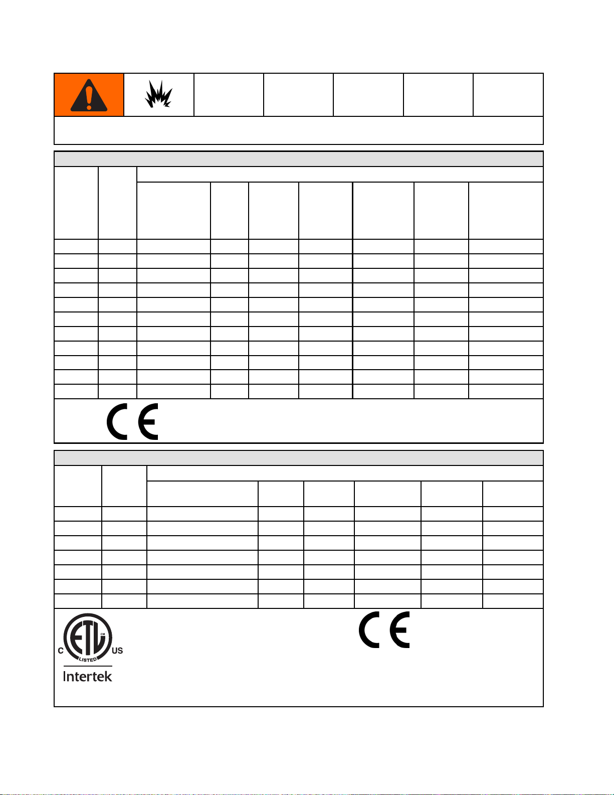
ProControl 1KE Models and Kits
ProControl 1K
All Advanced Display Control Modules (ADCM) are base model number 24L097 (Ref. 1). Models 24L097 and
24N672 (ADCM with bracket) are not available for separate sale. See approval information in Manual 332013
and on this page. The small label (Ref. 2) on the back of the module shows the ProControl 1KE Kit number.
Available kits are described in the tables that follow.
E Models and Kits
Model No.
7
24L09
2
24N67
trinsically Safe Apparatus
In
art of Intrinsically Safe System.
P
or use in Class I, Division 1, Group D T3 Hazardous Locations
F
See Manual 332013, Appendix A, Control Drawing 16M169 for entity parameters.
Series
A
A
ss I,Div. 1,
Cla
Gro
Ex
=0°C to 50°C
Ta
Description
Advan
33201
Advan
See M
2471
990
up D T3
ia [ia]
ced Display Control Module (ADCM), with no software loaded. See Manual
3.
ced Display Control Module (ADCM) with bracket, with no software loaded.
anual 332013.
3A2614H 3
Page 4
ProControl 1KE Models and Kits
ProControl 1KE systems are not approved for use in hazardous locations unless all accessories and all
wiring meet local, state, and national codes.
Kits for Hazardous Locations
Kit No.
24L083
24R261
24R262
24R263
24L085
24P593
24P595
24L087
24P597
24L089
24L091
Series
A
A
A
A
A
A
A
A
A
A
A
Configuration
ProControl
1KE Module
with bracket
(Manual
332013)*
✔✔
✔✔ ✔✔
✔✔ ✔✔✔
✔✔ ✔✔
✔✔✔✔
✔✔✔ ✔
✔✔✔✔
✔✔✔✔✔
✔✔✔✔✔
✔✔✔✔✔✔
✔✔✔
No
Power
* See component manuals for additional approval information.
** Must not be installed in Hazardous Location.
AC
Power
with
barrier**
G3000
Meter
(Manual
308778)*
I/P
Transducer
Fluid
Regulator
(Manual
3A0427)*
Pressure
Transducer
(Manual
407045)*
r Non-Hazardous Locations
Kits fo
Kit No.
84
24L0
24P592
24P594
24L086
24P596
24L088
L090
24
9902471
Conforms to/Certified to UL/CSA Standard 61010–1
Serie
A
A
A
A
A
A
A
s
ntrol 1KE
ProCo
ewithbracket
Modul
✔✔✔✔
✔✔✔ ✔
✔✔✔✔
✔✔✔✔✔
✔✔✔✔✔
✔✔✔✔✔✔
✔✔✔
AC
Power
Config
G3000
Meter
uration
I/P
Transducer
Fluid
Regulator
Pressure
Transducer
4
3A2614H
Page 5
Warnings
Warnings
The following warnings are for the setup, use, grounding, maintenance and repair of this equipment. The
exclamation point symbol alerts you to a general warning and the hazard symbol refers to procedure-specific
risks. When these symbols appear in the body of this manual or on warning labels, refer back to these
Warnings. Product-specific hazard symbols and warnings not covered in this section may appear throughout
the body of this manual where applicable.
WARNING
FIRE AND EXPLOSION HAZARD
Flammable fumes, such as solvent and paint fumes, in work area can ignite or explode. To help
prevent fire and explosion:
• Use equipment only in well ventilated area.
• Eliminate all ignition sources; such as pilot lights, cigarettes, portable electric lamps, and
plastic drop cloths (potential static arc).
• Keep work area free of debris, including solvent, rags and gasoline.
• Do not plug or unplug power cords, or turn power or light switches on or off when flammable
fumes are present.
• Ground all equipment in the work area. See Grounding instructions.
• Use only grounded hoses.
• Hold gun firmly to side of grounded pail when triggering into pail. Do not use pail liners unless
they are antistatic or conductive.
• Stop operation immediately if static sparking occurs or you feel a shock. Do not use
equipment until you identify and correct the problem.
• Keep a working fire extinguisher in the work area.
Static charge may build up on plastic parts during cleaning and could discharge and ignite
flammable vapors. To help prevent fire and explosion:
• Clean plastic parts only in a well ventilated area.
• Do not clean with a dry cloth.
ELECTRIC SHOCK HAZARD
This equipment must be grounded. Improper grounding, setup, or usage of the system can
cause electric shock.
• Turn off and disconnect power at main switch before disconnecting any cables and before
servicing or installing equipment.
• Connect only to grounded power source or grounded electrical outlets.
• Use only 3–wire extension cords.
• Ensure ground prongs are intact on power and extension cords.
• Do not expose to rain. Store indoors.
• All electrical wiring must be done by a qualified electrician and comply with all local codes
and regulations.
3A2614H 5
Page 6
Warnings
WARNING
INTRINSIC SAFETY
Intrinsically safe equipment that is installed improperly or connected to non-intrinsically safe
equipment will create a hazardous condition and can cause fire, explosion, or electric shock.
Follow local regulations and the following safety requirements.
• Be sure your installation complies with national, state, and local codes for the installation of
electrical apparatus in a Class I, Group D, Division 1 Hazardous Location, including all of the
local safety fire codes, NFPA 33, NEC 500 and 516, and OSHA 1910.107.
• Equipment that comes in contact with intrinsically safe terminals must meet the entity
parameter requirements specified in Control Drawing 16M169. See Appendix A in Manual
332013. This includes safety barriers, DC voltage meters, ohmmeters, cables, and
connections. Remove the unit from the hazardous area when servicing.
• If a printer, computer, or other electrical component is connected, it must be used in
conjunction with a safety barrier.
• Without the safety barrier, the equipment is no longer intrinsically safe and must not be
operated in hazardous locations, as defined in article 500 of the National Electrical Code
(USA) or your local electrical code.
• Do not install equipment approved only for non-hazardous location in a hazardous area. See
the ID label for the intrinsic safety rating for your model.
• Ground the power supply. A voltage limiting safety barrier must be properly grounded to be
effective. For proper grounding, use a 12 gauge minimum ground wire. The barrier’s ground
must be within 1 ohm of true earth ground.
• Do not operate the power supply module with the cover removed.
• Do not substitute system components as this may impair intrinsic safety.
SKIN INJECTION HAZARD
High-pressure fluid from gun, hose leaks, or ruptured components will pierce skin. This may
look like just a cut, but it is a serious injury that can result in amputation. Get immediate surgical
treatment.
• Engage trigger lock when not spraying.
• Do not point gun at anyone or at any part of the body.
• Do not put your hand over the spray tip.
• Do not stop or deflect leaks with your hand, body, glove, or rag.
• Follow the Pressure Relief Procedure when you stop spraying and before cleaning, checking,
or servicing equipment.
• Tighten all fluid connections before operating the equipment.
• Check hoses and couplings daily. Replace worn or damaged parts immediately.
6 3A2614H
Page 7
Warnings
WARNING
EQUIPMENT MISUSE HAZARD
Misuse can cause death or serious injury.
• Do not operate the unit when fatigued or under the influence of drugs or alcohol.
• Do not exceed the maximum working pressure or temperature rating of the lowest rated
system component. See Technical Data in all equipment manuals.
• Use fluids and solvents that are compatible with equipment wetted parts. See Technical Data
in all equipment manuals. Read fluid and solvent manufacturer’s warnings. For complete
information about your material, request MSDS from distributor or retailer.
• Do not leave the work area while equipment is energized or under pressure.
• Turn off all equipment and follow the Pressure Relief Procedure when equipment is not in use.
• Check equipment daily. Repair or replace worn or damaged parts immediately with genuine
manufacturer’s replacement parts only.
• Do not alter or modify equipment. Alterations or modifications may void agency approvals
and create safety hazards.
• Make sure all equipment is rated and approved for the environment in which youareusingit.
• Use equipment only for its intended purpose. Call your distributor for information.
• Route hoses and cables away from traffic areas, sharp edges, moving parts, and hot surfaces.
• Do not kink or over bend hoses or use hoses to pull equipment.
• Keep children and animals away from work area.
• Comply with all applicable safety regulations.
TOXIC FLUID OR FUMES
Toxic fluids or fumes can cause serious injury or death if splashed in the eyesoronskin,
inhaled, or swallowed.
• Read MSDSs to know the specific hazards of the fluids you are using.
• Store hazardous fluid in approved containers, and dispose of it according to applicable
guidelines.
PERSONAL PROTECTIVE EQUIPMENT
Wear appropriate protective equipment when in the work area to help prevent serious injury,
including eye injury, hearing loss, inhalation of toxic fumes, and burns. This protective
equipment includes but is not limited to:
• Protective eyewear, and hearing protection.
• Respirators, protective clothing, and gloves as recommended by the fluid and solvent
manufacturer.
3A2614H
7
Page 8

Overview
Overview
The ProControl 1KE Advanced Display Control
Module is an electronic flow control and fluid
monitoring system. The ProControl 1KE performs the
following functions:
• Manages fluid
• Manages the f
•Showsreal-
•Displaysar
• Monitors an
•Alarmsift
the user-s
•Alarmswhe
the user-s
•Displays
pressure or flow rate.
an air.
time fluid flow rate.
esettable batch totalizer.
d reports overall fluid use.
he flow rate is too fast or too slow for
et targets.
n the maintenance total is reached for
et target.
alogofthelast20alarms.
The ProControl 1KE is available in configurations for
installation in Hazardous Locations or Non-Hazardous
locations. The power supply for Hazardous Locations
comes with one barrier, to power one ProControl
1KE. Up to three additional barriers can be added
to the power supply to power three additional
ProControl 1KEs. See Accessories, page 43 ,to
order additional barriers. Order ProControl 1KE Kit
24R261, 24R262, or 24R263,, based on your choice
of the fluid management compononets. These kits do
not include a power supply.
8 3A2614H
Page 9
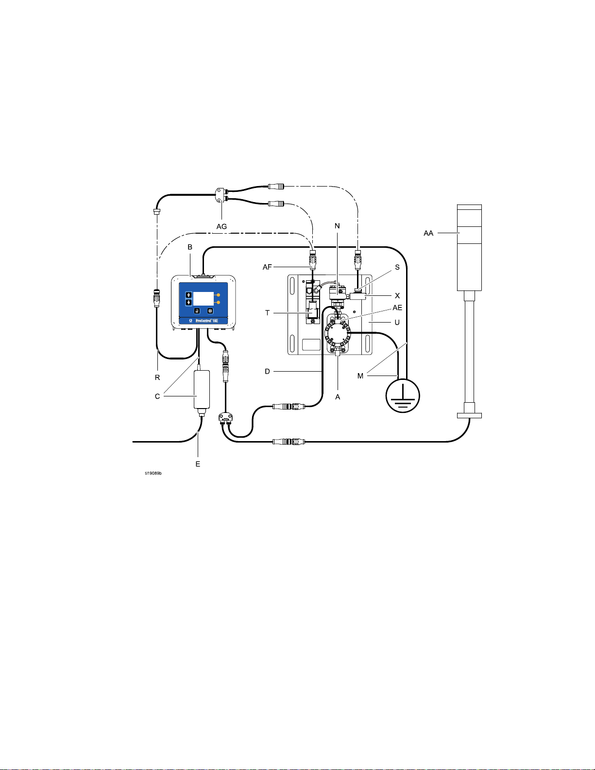
Installation
Non-Hazardous Locations
Installation
NOTE: Kits su
Users in area
converter. S
pplied with an AC/DC Converter are shipped with a North American 120 VAC power cord (E).
s with another standard voltage must provide a power supply cord with an IEC 320–C13 female
ee Technical Data, page 53 for power requirements.
Key:
A
Flow Meter Fluid Inlet, 1/4 npt female
inlet/outlet.
B
C Power Supply and Cable (6 ft., 2 m), to
D
E
M
N
Control 1KE Module with Bracket
Pro
terminal 3. See Cable Connections, page 13.
Meter Cable (50 ft., 15 m), to terminal 4. See
Cable Connections, page 13.
ower Cord (10 ft., 3 m), see NOTE above.
P
Ground wire and clamp. PN 244524 in
included with kits to ground the ProControl
1KE Module. PN 238909 is sold separately
to ground the meter and other components.
Fluid Regulator, 1/8 npt (f) outlet
R
S
T
U
X
A
AE
AF
A
d Control Cable
Flui
Pressure Transducer
I/P Transducer (Current to Pressure). See
Air Connections, page 15.
unting Panel. See
Mo
unting Dimensions, page 44.
Mo
Pressure Transducer Fitting, 1/8 npt (f) inlet
and outlet
Light Tower with Splitter (accessory)
Flow Meter Fluid Outlet, 1/4 npt (f)
Pressure Transducer Cable
3A2614H 9
Page 10
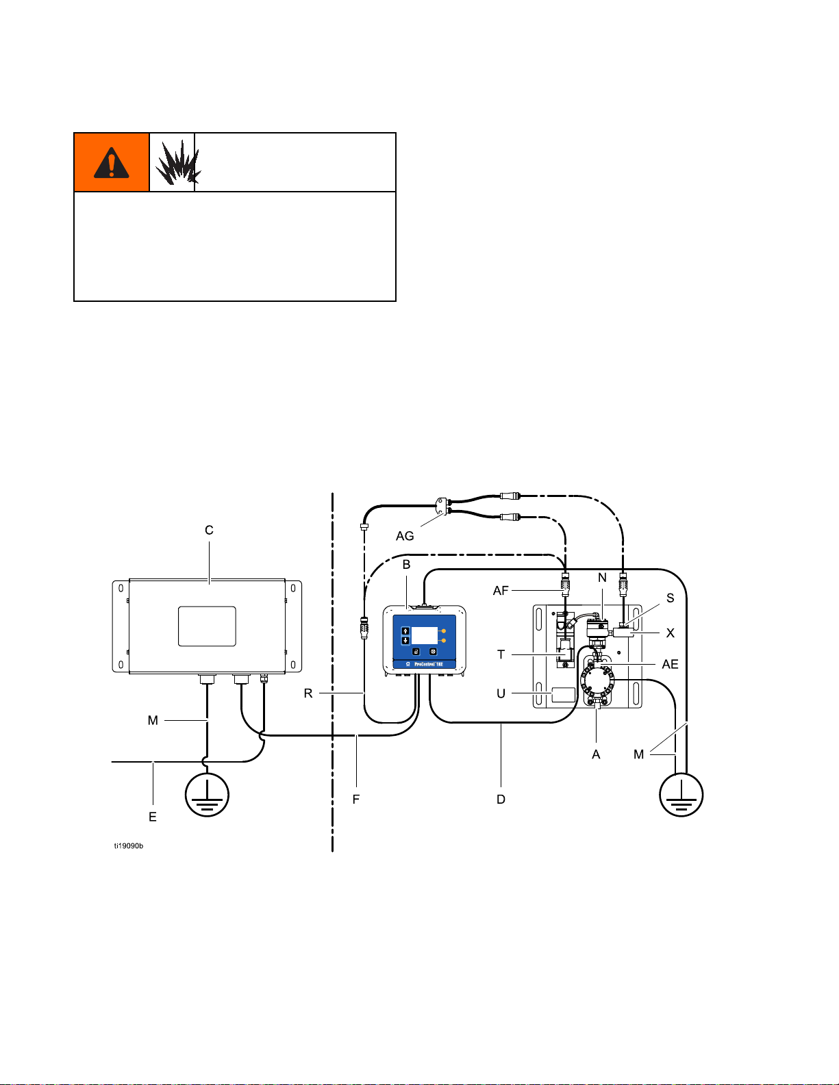
Installation
Hazardous Locations
Do not substit
as this may imp
maintenance,
instruction m
approved onl
hazardous lo
the intrinsi
Intrinsica
power suppl
from a non-I
that has bee
not be retur
an intrinsi
ute or modify system components
air intrinsic safety. For installation,
or operation instructions, read
anuals. Do not install equipment
y for non-hazardous location in a
cation. See the identification label for
c safety rating for your model.
lly safe equipment should not be used with a
y that has no barrier. Do not move units
S setup to an IS setup. IS equipment
n used with a non-IS power supply must
ned to a hazardous location. Always use
cally safe power supply with IS equipment.
• Installation should be in accordance with ANSI/ISA
RP12.06.01, “Installation of Intrinsically Safe
Systems for Hazardous (Classified) Locations,”
and the National Electrical Code® (ANSI/NFPA
70).
• Installation in Canada should be in accordance
with the Canadian Electrical Code, CSA C22.1,
Part 1, Appendix F.
• For ATEX, install per EN 60079-14 and applicable
local and national codes.
• Multiple earthing of components is allowed only
if a high integrity equipotential system is realized
between the points of bonding.
• Do not remove any cover until power has been
removed.
• Install according to Control Drawing Number
16M169. See Appendix A in Manual 332013.
Nonhazar
dous Location
Hazardou
s Location
10 3A2614H
Page 11

Installation
Key:
A
Flow Meter, 1/4 npt female inlet/outlet
B
ProControl 1KE Module with Bracket
C Power Supply
D
Meter Cable (50 ft., 15 m), to terminal 4. See
Cable Connections, page 13.
E
Power Cord (not supplied)
F
Power Cabl
Cable Conn
M
Ground wire and clamp. PN 244524 is
included with kits to ground the ProControl
1KE Module. PN 238909 is sold separately
to ground the meter or other component.
with Barrier
e(50ft.,15m)toterminal3.See
ections, page 13.
N Fluid Regulato
R
Fluid Control Cable
Pressure Tran
S
T
I/P Transduc
Air Connecti
U
Mounting Panel. See
Mounting Dimensions, page 44.
X
Pressure Transducer Fitting, 1/8 npt (f) inlet
and outlet
AE
Flow Mete
AF
Pressure Transducer Cable
r
sducer
er (Current to Pressure). See
ons, page 15.
r Fluid Outlet, 1/4 npt (f)
3A2614H
11
Page 12

Installation
Grounding
The equipment must be grounded to reduce the
risk of static sparking and electric shock. Electric
or static sparking can cause fumes to ignite or
explode. Improper grounding can cause electric
shock. Grounding provides an escape wire for the
electric current.
NOTE: The ProControl 1KE does not provide 500
VAC isolation through the coupling nuts on the
enclosure. The associated apparatus and the field
apparatus cable shields must not be connected to
the ProControl 1KE coupling nuts.
1. Power Supply 16M167: Connect the ground wire
from the power supply to a true earth ground.
2. ProControl 1KE Module: Connect a ground
wireandclamptothescrewonthetopofthe
bracket. Connect the other end to ground. In an
IS system, the ProControl 1KE also is grounded
by connection to the grounded power supply.
3. Flow Meter: Follow the instructions in manual
308778 (G3000) or manual 313599 (Coriolis) to
ground the flow meter and check its electrical
grounding continuity.
4. Fluid and Air Control: Ground through connection
to the mounting panel that also holds the
grounded flow meter.
5. Fluid Supply: Ground the fluid supply unit.
2
1
3A2614H
Page 13
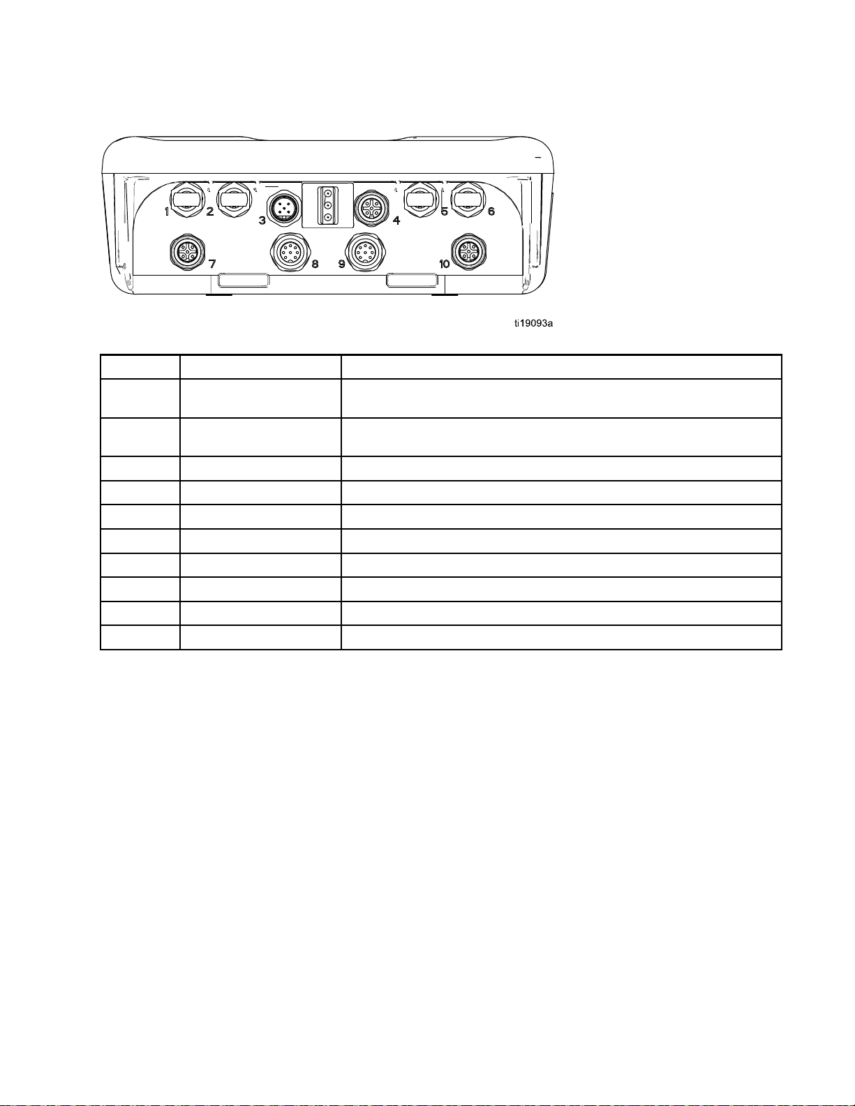
Installation
Cable Connect
Port Descripti
1
2
3 Power
4
Fiber Opt
Fiber Optic Transmitter Black Lead to RX on Fiber Optic Converter (PN 16K465) or to Port
Digita
ions
on
ic Receiver
l Input/Output
Connection
RedLeadf
Port6ona
5 on another ProControl 1KE (or Informer)
From Power Supply
To/Fro
rom TX on Fiber Optic Converter (PN 16K465) or from
nother ProControl 1KE (or Informer)
m Meter and Light Tower (Accessory)
5
6
7
8
9
10
Fiber Optic Reciever Black Lead from Port 2 on another ProControl 1KE (or Informer)
Fiber Optic Transmitter Red Lead to Port 1 on another ProControl 1KE (or Informer)
Analog Input
Flow Control To/From Flow Control Cable
Motor Control
gital Input/Output
Di
rom Pressure Transducer Cable
To/F
used.
Not
Not used.
3A2614H 13
Page 14
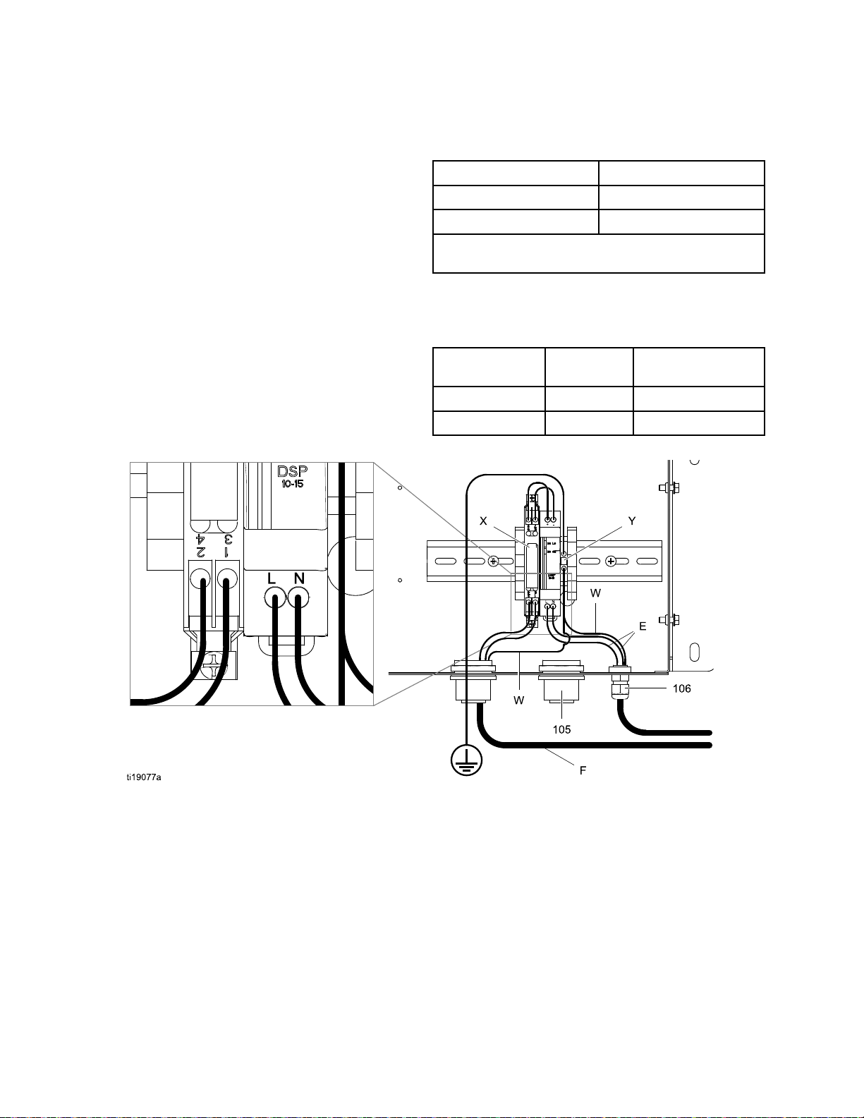
Installation
Electrical Co
Install per Graco Control Drawing 16M169, in Manual
332013. See also Figure 1.
1. Connect main power supply cord (E, not
supplied) through strain relief to terminals L and
N on the power supply unit.
Note: Use either strain relief (5) or (6), depending
onthesizeofthecord.
2. Connect power cord ground wire (W) to ground
terminal block (Y).
3. Connect IS power cable (F) per the following
table.
nnections
Table 1 Power Barrier Wiring Connections
Power Cable Leads Barrier Connection
Brown (power) Connector 1
Blue (common) Connector 2
Glossy Black (ground) and Black (drain) connect to
ground block.
Table 2 I/P Transducer Wiring Connections; Cables 16P790 (non-IS) and 16V142 (IS)
Wiring Table
Wire Color
Gray Control A Connector 1
Blue
Function
Common Connector 2
DIN Connector
Figure 1
KEY
E
F
W
XBarrier
Y
5
6
4
1
Inbound AC Power Cord
Power Cable
Ground Wires
Ground Block
Strain Relief Fitting
Strain Relief Fitting
3A2614H
Page 15
Installation
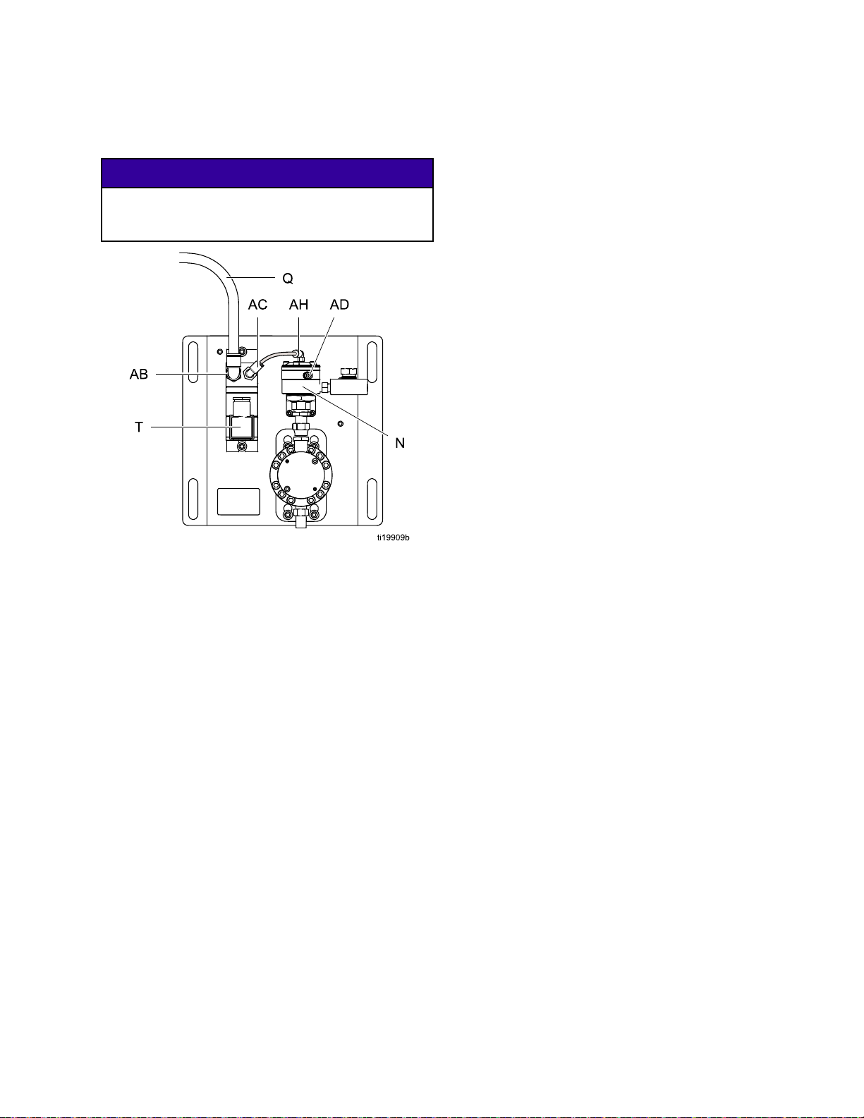
Air Connectio
ns
NOTICE
To avoid damage to the I/P transducer, use clean,
dry, oil-free air, filtered through at least a 40 micron
filter.
1. Connect incoming air line (Q) to 1/4 in. npt (f)
inlet (AB) on I/P transducer (T). Kits with a fluid
regulator (See Parts, page 34), include a 3/8
tube fitting.
2. Kits with fluid regulator: Check that the air tube
isconnectedfrom5/32tubefitting(AC)onI/P
transducer to 5/32 tube fitting (AH) on fluid
regulator (N).
Other Kits: The air outlet is 1/4 in npt (f).
The I/P trans
whenever air
is operatin
NOTE:
• The side port (AD) on the fluid regulator can be
used for high-speed flushing with an independent
air source. Set the air pressure higher than the top
port (AH) air pressure.
• Flushing air pressure must be removed from the
side port (AD) to return to the previous flow setting.
ducer exhausts a small amount of air
is connected, whether or not the system
g.
Communication Options
Graco Accessories are available to enable
communication with a Programmable Logic
Controller (PLC) or Personal Computer (PC).
•TheFi
•AModb
ber Optic Converter (Graco Kit 24N978)
es Modbus RTU communication with a
enabl
supplied PLC using a serial cable.
user-
us Gateway (Graco Kit 24N977) used
Fiber Optic Converter (Graco Kit 24N978)
with a
les Modbus TCP communication with a
enab
-suppled PLC.
user
• A Modbus Gateway (Graco Kit 24N977)
canbeconnectedto(orinstalledin)
an Advanced Web Interface (Graco
Kit 15V377) to enable communication
with a PC using an ethernet cable. See
Appendix B - Advanced Web Interface, page 48,
for instructions.
These communication kits come with installation
and setup directions necessary for their use with the
ProControl 1KE.
3A2614H 15
Page 16
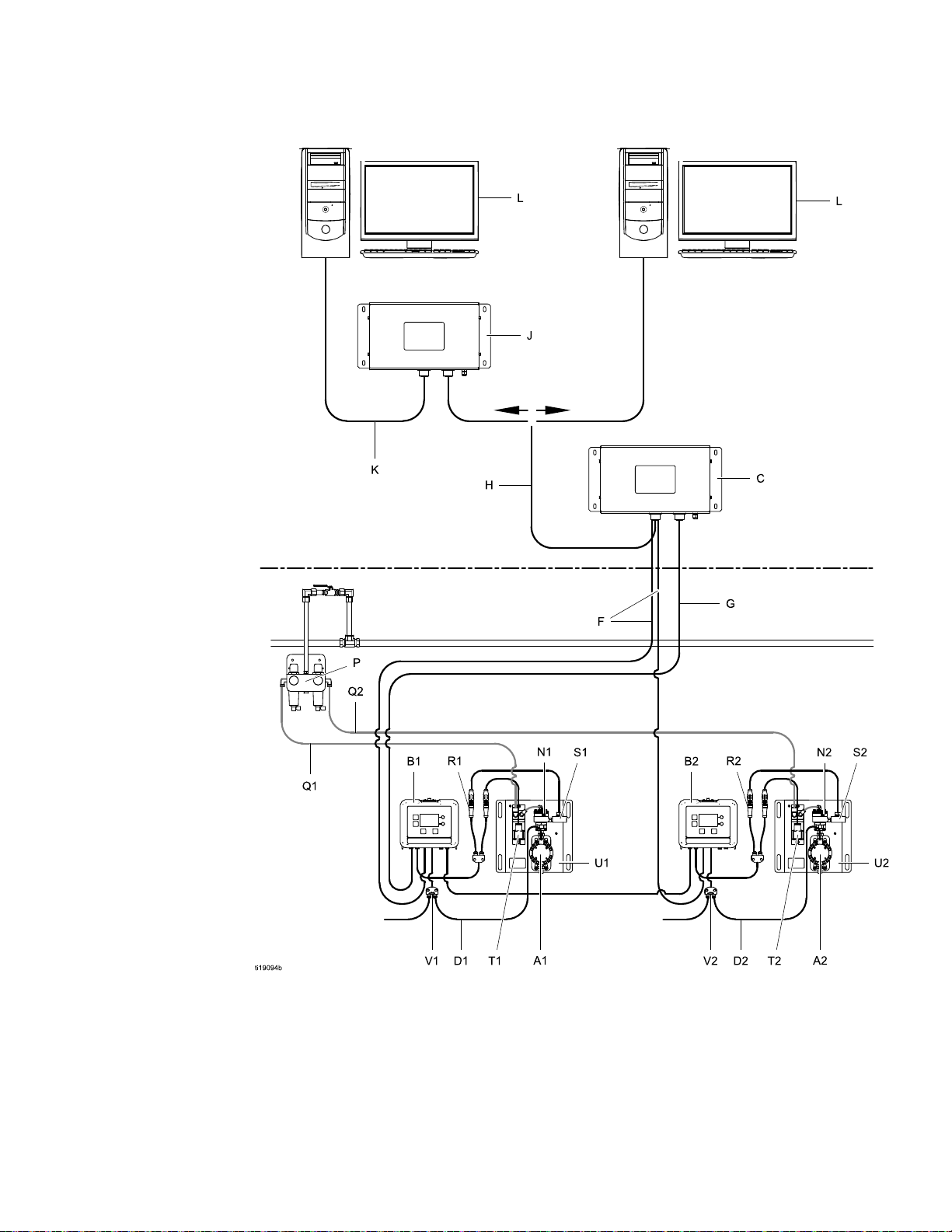
Installation
Typical Installation
Non-Hazardous
Location
Hazardous Location
16 3A2614H
Page 17

Installation
Key
A1 and A2
B1 and B2 ProControl 1K
C Power Supply a
D1 and D2 Meter Cable (50 ft., 15 m) Supplied in kits with meter
E
F
G Fiber Optic Cable (100 ft., 30 m)
H
J
K
L Personal computer Not supplied.
N1 and N2
P
Q1 and Q2
R1 and R2 Flow Con
S1 and S
T1 and T2 I/P Transducer (Current to Pressure) Supplied
U1 and U2
V1 and V2 Splitter to meter and light tower
W1 and W2 Pressure Transducer Cable. Supplied in some kits. See
2
Flow Meter
EModulewithBracket
nd Barrier
Power Cord (10 ft., 3 m), not shown Supplied in Non-Hazardous
Power Cable (50 ft., 15 m) Supplied
Serial Cable
Advanced Web Interface
Ethernet Cable
Fluid Regulator
Air Cont
Air Lines Not supplied
Pressure Transducer
Mounti
(non-hazardous installations) or IS cable
kit for hazardous location installations.
rol Module
trol Cable
ng Panel
Supplied in some kits. See
Parts, page 34.
Supplied
SuppliedinHa
Kits
Location Kits
Accessory
Accessory
Accessory
Accessory
Supplied in some kits. See
Parts, page 34.
Accessory
Supplie
Suppli
Parts,
Supplied
Acces
Parts, page 34.
d
ed in some kits. See
page 34.
sory
zardous Location
3A2614H
17
Page 18

Operation
Operation
Flow Meter Operation
Pressure Relief Procedure
Follow the Pressure Relief Procedure
whenever you see this symbol.
This equipment stays pressurized until pressure
is manually relieved. To help prevent serious
injury from pressurized fluid, such as skin injection,
splashing fluid and moving parts, follow the
Pressure Relief Procedure when you stop spraying
and before cleaning, checking, or servicing the
equipment.
1. Turn off the fluid supply to the meter.
2. Set the Flow Rate Percent to at least 50 percent.
3. Follow the Pressure Relief Procedure for your
fluid system dispensing device.
4. Reduce the Flow Rate Percent to 0 percent.
NOTICE
To avoid damage to the I/P transducer, always
set the Flow Rate Percent to 0 before reducing air
pressure to the system.
Fluid Regulator Operation
To reduce the risk of component rupture, which
could cause injury from splashing fluid, do not
exceed the maximum working pressure of your
meter or any component or accessory in your
system.
For information on the G3000 Graco flow meter, see
manual 308778. For information on the Coriolis flow
meter, see manual 313599. Calibrate the meter as
instructed before using the meter for production.
NOTICE
The flow meter gears and bearings can be
damaged if they rotate at too high a speed. To
avoid high speed rotation, open the fluid valve
gradually. Do not over-speed the gear with air or
solvent. To prolong meter life, do not use the meter
above its maximum flow rate.
Calibrate the Meter
NOTE: See Setup Screen 5 for further screen
information, if needed.
When to Calibrate
• The first time the system is operated.
• Whenever new materials are used in the system,
especially if the materials have viscosities that
differ significantly.
• As part of regular maintenance to retain meter
accuracy.
• Whenever a flow meter is serviced or replaced.
Follow instructions in the fluid regulator manual to set
up, flush, and adjust the fluid regulator prior to use.
18 3A2614H
Read Before Calibration
• Meter k-factor on Setup Screen 5 is updated
automatically after the calibration procedure is
completed. You also may manually edit the
k-factor if desired.
• All values on this screen are in cc or cc/pulse,
regardless of the units set in the other Setup
screens.
• Before calibrating the meter, be sure the system
is primed with material.
• Disable alarms before calibration.
Page 19

Operation
Calibration Steps
1. Press
2. Press
3. Press
4. Press
5. Dispense about 300–500 cc of material into a
graduated cylinder. The amount the system
measures will display in the measured volume
field
6. Press
7. Press
the amount of material in the cylinder.
8. After the volume is entered, the system calculates
the new k-factor and shows it on Setup Screen 5.
NOTE: T
calibration again, press
another screen, then return to Setup Screen 4
and start over. If you press
the screen, the counter will continue from where
it is, without clearing.
to enter Setup Mode.
to move
to enter the screen.
to begin the calibration.
.
to e
to get to the dispensed volume field
,thenpress to enter the field. Enter
o clear the counter and begin the
to Setup Screen 5.
nd the calibration.
,movebrieflyto
without leaving
Set the Flow Ra
1. System Setup: See SetupScreen2,page27to
set the upper and lower limit within which the
operator can adjust the flow rate. The settable
range is 0 to 99.9 percent, but the I/P pressure
transducer requires a minimum of 22 to 25 flow
rate percent target to start flow. Therefore, the
operational range is about 22 to 99.9 percent.
See Table 1.
Table 3
Flow Rate
Target
0–about 20
percent
22%-25%
55% — 60%
99.9%
2. Operator: See Run Screen 1, page 24 to adjust
the flow rate within the set limits.
te Percent
I/P Current Effect
0–4.0 mA
4.4–5.0 mA
11–12 mA
20 mA
No flow
Lowest flow
rate
Middle flo
rate
Highest flow
rate
w
Update the Software
9. Press
10. Press
to exit the screen.
to exit Setup Mode.
Set the Modbus Addresses
See Setup Screen 7. By default, the Modbus is
set to Off
Modbus mode to SLAVE
value is between 1 and 247. The modbus address
corresponds to the address of the ProControl 1KE.
See Appendix A for further information.
. If you need the Modbus, set the
. The address
Software updates are installed using a software token
(PN 16P892), which is sent automatically when a new
version of the software is released. Manual 3A1244
will accompany any necessary software updates.
Follow all instructions and warnings in Manual
3A1244 to update your ProControl 1KE software.
3A2614H 19
Page 20

Operation
Replace the Battery
Replace the ba
after disconn
Sparking can occur when changing the battery.
Replace the battery only in a non-hazardous
location, away from flammable fluids or fumes.
ttery only if the clock stops functioning
ecting power or a power failure.
NOTICE
To avoid dam
112190 grou
1. Disconnect
2. Remove the m
3. Attach the
4. Remove4sc
cover.
age to the circuit board, wear Part No.
nding strap, and ground appropriately.
power.
odule from the bracket.
grounding strap.
rews, and then remove the access
5. Use a flathead s
battery.
NOTE: Dispose of battery properly in an
approved container and according to applicable
local guidelines.
6. Replace with new battery. Ensure battery fits
under connector tabs before snapping other end
in place.
NOTE: Us
replace
7. Reassem
8. Snap the
ment.
ble access cover and screws.
crewdriver to pry out the old
e only Panasonic CR2032 batteries for
module back into the bracket.
20 3A2614H
Page 21

Display Module
Display Module
Display Information
The Display M
to enter sele
setup and op
The screen backlight is factory set to remain on,
even without screen activity. See Setup Screen 4
to set the backlight timer to your preference. Press
any key to restore.
Keys are used to input numerical data, enter setup
screens, navigate within a screen, scroll through
screens, and select setup values.
odule provides the interface for users
ctions and view information related to
eration.
NOTICE
To prevent damage to the softkey buttons, do not
press the buttons with sharp objects such as pens,
plastic cards, or fingernails.
Operation Modes
The ProControl 1KE has two operation modes: Run
Mode and Setup Mode. For detailed information see
Run Screens, page 24, and SetupScreens,page26.
Press
to toggle between these two modes.
3. Use
change.
4. Press
Drop Down Field
1. Use
the dropdown menu.
2. Press
3. Press
Number Field
1. The first digit will be highlighted. Use
to change the number.
2. Press
3. When all digits are correct, press
accept.
4. Press
Check Box Field
A check box field is used to enable or disable features
in the software.
to highlight the data you wish to
to edit.
to highlight the correct choice from
to select.
to cancel.
to move to the next digit.
again to
to cancel.
Screen Navigation and Editing
Refer to this section if you have questions about
screen navigation or about how to enter information
and make selections.
All Screens
1. Use
2. Press
on the screen will highlight.
to move between screens.
to enter a screen. The first data field
1. Press
box.
2. The feature is enabled if a
Reset Field
e reset field is used for totalizers. Press
Th
set the field to zero.
re
When all data is correct, press
Then use
to move between Setup Mode and Run Mode.
to toggle between and an empty
is in the box.
to exit the screen.
to move to a new screen, or
to
3A2614H
21
Page 22

Display Module
Icons
Asyoumovethr
using icons ra
Run Screens, p
also are provi
the screen con
ough the ProControl 1KE screens, you will notice that most information is communicated
ther than words to simplify global communication. The detailed screen descriptions in
age 24, and Setup Screens, page 26, explain what each icon represents. Icon reference tables
ded, on this page and the next. Softkeys are membrane buttons whose function correlates with
tent to the immediate left of the button.
Membrane Keys
Press to toggle between Run mode
and Setup Mode.
Softkeys
Enter Screen.
Also changes the function of the Up/Down
arrows so they move between data fields on the
screen, rather than between screens.
Highlight data that can be edited.
Error Reset:
has been fixed. Also used to cancel data
entered and return to original data.
Up/Down Arrows:
screens or fields on a screen, or to increment
or decrement the digits in a settable field.
Softkeys:
Use to clear alarm after cause
Usetomovebetween
Use varies by screen.
See column at right.
Exit Screen.
Enter.
Right.
Presstoactivateafieldforeditingortoaccept
the highlighted selection on a dropdown menu.
Move to the right when editing number fields. Press
again to accept the entry when all digits are correct.
Reset.
Exit data editing.
Reset totalizer to zero.
Start
Stop
2
2
3A2614H
Page 23

Display Module
Screen Icons
Screen number.
The arrows indicate
more screens are
available to view.
Batch Totalizer Batch Units
Maintenance Totalizer
Grand Totalizer Set Grand Total Units
Lock icon indicates
the unit is in Setup.
Maintenance Target
Screen Icons
Set Pressure Units
Set Flow Rate Units
Flow Rate Alarm
Enable
Set Backlight Timer
Actual vo
dispense
lume
d
Set Maximum and
Minimum Flow Rates
Maintenance Totalizer
Alarm Enable
Set Alarm Auto Clear
(to clear alarm on ac-
cessories)
Volume measured
by the meter
K-Factor
Fluid Flow Percent
Target
Fluid Flow Rate
Set Modbus Address Set Serial Port Baudrate
SetSerialPortParity
Set Upper and Lower
Limits for Fluid Flow
Percent
Fluid Pressure
Set Mod
Modbus Functionality is
Off
ProControl 1KE is
bus Mode
Modbus Slave
Select Pressure
Transducer
Display or adjust pres-
sure transducer slope
MF
Maintenance Alarm
Select Correct Date Select Date Format
Set the Correct Time
Set Zero Offset
F3
Flow Rate High Alarm
F2
Flow Rate Low Alarm
Enter User-Set
Password
3A2614H 23
Page 24

Run Screens
Run Screens
When in Run Mode, the ProControl 1KE displays the
flow rate percent target, actual fluid pressure, and
current flow rate on Screen 1. Screen 2 displays
the batch total and grand total for the flow meter to
which it is connected. Screens 3–6 display a log of
the last 20 alarms.
Run Screen 1
Use this screen to view or reset the flow rate percent
target, and to view the actual fluid pressure and flow
rate. Units are set on Setup Screen 1 and Setup
Screen 2.
Key
Enter the screen.
Flow Rate Percent Target — Operator
settable within the range defined on
SetupScreen2.
Displays current fluid pressure if
equipped and set up with a pressure
transducer. Otherwise, this field displays
just 3 dashes.
Displays current flow rate.
Run Screen 2
Use this screen to view or reset the batch totalizer
and to view the grand total flow for the system. The
grand total cannot be reset.
Key
Batch Totalizer - Displays the amount
of fluid measured since the last time the
field was reset to zero.
Reset Batch Totalizer - resets the batch
totalizer to zero.
Grand Totalizer - Displays the grand total
flow for the system. This value cannot
be reset.
Move between Run Screens.
Move between Run Screens.
4
2
3A2614H
Page 25

Password Screen
Run Screens 3 —
Use Screens 3–6 to view the log of recent alarms.
Date on whi
Alarm occ
Time at which the Deviation or Advisory
Alarm occurred.
General
advisor
alarm. F
F3 is the
Deviat
more in
Move between Run Screens.
yalarm.MF is the maintenance
ions and Advisories, page 31,for
formation.
6
Key
ch the Deviation or Advisory
urred.
symbol indicating a deviation or
2 is the flow rate low alarm.
flowratehighalarm. See
Enter password to enable entry to the Setup screens.
Set the password to 0000 to disable password
protection. See Setup Screen 9 to set or change
the password.
Key
Enter the s
Press to activate a field for editing.
Move to the right when editing number
fields. Press again to accept the entry
when all digits are correct.
Enter the user-set password for the
system.
Increm
editin
creen to enter a password.
ent/decrement the digits when
g number fields.
Password Screen
assword has been set, the Password Screen
If a p
displays when
3A2614H 25
is pressed from any Run screen.
Page 26

Setup Screens
Setup Screens
The Setup Mode
(if desired) a
and monitorin
See Screen Na
information
data.
is used to set up a password
nd to set parameters for controlling
gfluidflowwiththeProControl1KE.
vigation and Editing, page 21,for
on how to make selections and enter
SetupScreen1
Use this sc
totalizer
the batch a
Screens. M
Setup Scre
reen to view and reset the maintenance
, set the maintenance target value, and set
nd grand totalizer units shown on the Run
aintenance totalizer units, shown on this
en, are always cc.
Enter the screen to set or change
preferences.
Press to activate a field for editing or
to accept the highlighted selection on a
dropdown menu.
Move to the right when editing number
fields. Press again to accept the entry
when all digits are correct.
Key
Reset Mainten
maintenance t
Maintenance Totalizer - Displays the
current maintenance total in cubic
centimeters.
Set your desired maintenance total target
value in this field in cubic centimeters.
See SetupScreen4,page28,tosetor
disable the maintenance alarm.
Batch Totalizer Units - Select from the
following drop down options.
Cubic centimeters
Liters
Gallons
Grand Totalizer Units - Select from the
following drop down options.
Cubic c
Liters
Gallons
Exit data editing.
Move between Setup Screens, fields on
a screen, or to increment/decrement the
digits when editing number fields.
ance Totalizer - resets the
otalizer to zero.
entimeters
26 3A2614H
Page 27

Setup Screens
Setup Screen 2
Use this screen to set the upper and lower limits for
operator adjustment of flow rate percent and to select
your preferred pressure units.
Key
Enter the screen to set or change
preferences.
Press to activate a field for editing or to
accept the highlighted selection on a
dropdown menu.
Move to t
fields. P
when al
Set you
and low
perce
adjus
only w
Press
foll
transducer.
he right when editing number
ress again to accept the entry
l digits are correct.
r desired upper (first data field)
er (second data field) fluid flow
nt set limits. The Operator can
t the percentage on Run Screen 1
ithin these limits.
ure units — select from the
owingdropdownoptions.
Select if system has no pressure
SetupScreen3
Use this screen to set your flow rate maximum and
minimum values and to select your preferred flow
rate units.
Key
Enter the screen to set or change
preferences.
Presstoactivateafieldforeditingorto
accept the highlighted selection on a
dropdown menu.
Move to the right when editing number
fields. Press again to accept the entry
when all digits are correct.
Set your desired maximum (first data
field) and minimum (second data field)
flow rates. Flow rates outside of these
parameters will trigger an alarm. See
Setup Screen 4, page 28, to set or
disable the flow rate alarms.
Flow Rate Units - Select from the
following drop down options.
Select if system has no flow
meter.
3A2614H
it data editing.
Ex
Move between Setup Screens, fields on
a screen, or to increment/decrement the
digits when editing number fields.
Exit data editing.
Move between Setup Screens, fields on
a screen, or to increment/decrement the
digits when editing number fields.
27
Page 28

Setup Screens
SetupScreen4
Use this screen to set your alarm preferences. Select
to enable the a
disable the al
Enter the
preferen
Press to t
Maintenance Totalizer Alarm Enable
Flow Rate Alarm Enable
Alarm Auto Clear Enable. If enabled,
whentheflowratereturnstowithinthe
flow limit set points, the flow rate alarm
will clear on the screen and on any
attached accessories, such as a the light
tower.
Set backlight timer. Enter “00” to set the
backlight to remain on.
Exit data editing.
Move between Setup Screens, fields on
a screen, or to increment/decrement the
digits when editing number fields.
larm, or leave the box empty to
arm.
Key
screen to set or change
ces.
oggle between
and blank.
Setup Screen 5
Use this screen to calibrate your meter and
to view or set your meter k-factor. See
Calibrate the Meter, page 18, for procedure.
Key
Enter the screen to set or change
preferences.
Press to activate a field for editing or
to accept the highlighted selection on a
dropdown menu.
Move to t
fields.
when al
Start t
Stop the calibration.
Displaysthevolumemeasuredbythe
system for the calibration test.
Enter the actual volume dispensed into
the cylinder for the calibration test.
Displays the meter k-factor. User can
set the k-factor manually. The system
automatically updates to the correct
k-factor when the meter is calibrated.
Exi
he right when editing number
Press again to accept the entry
l digits are correct.
he calibration.
t data editing.
Move between Setup Screens, fields on
a screen, or to increment/decrement the
digits when editing number fields.
28 3A2614H
Page 29

Setup Screens
Setup Screen 6
Use this screen to specify your pressure transducer
and set its offset and slope.
Key
Enter the
preferen
Press to
to accep
dropdow
Move to the right when editing number
fields. Press again to accept the entry
when all digits are correct.
Select the correct pressure transducer.
Set the zero offset (the reading on
thegaugewhennopressureisonthe
system).
Pressure transducer slope. This number
is a constant representing millivolts
per bar. The default matches the
selected pressure transducer. Operator
adustable.
Exit data editing.
Move between Setup Screens, fields on
a screen, or to increment/decrement the
digits when editing number fields.
screen to set or change
ces.
activate a field for editing or
t the highlighted selection on a
n menu.
SetupScreen7
Use this screen to set your modbus preferences
for ports 1 and 2. Note that ports 5 and 6 are used
as modbus master devices for connecting to other
ProControl 1KE (or Informer) modules.
Key
Modbus mode. Select off or Slave from
the dropdown options.
Turn off Modbus functionality if
not used.
Use ProC
slave de
Enter or change the Modbus address.
Value is between 1 and 247.
Select serial port baudrate from the
dropdown options: 9600, 19200, 38400,
57600, or 115200.
Select serial port parity from the
dropdown options: NONE, ODD, or
EVEN.
Exit data editing.
Move between Setup Screens, fields on
a screen, or to increment/decrement the
digits when editing number fields.
vice.
ontrol 1KE as Modbus
3A2614H 29
Page 30

Setup Screens
SetupScreen8
Use this screen to set your date format, date, and
time.
Key
Enter the screen to set or change
preferences.
Press to activate a field for editing or
to accept the highlighted selection on a
dropdown menu.
Move to the right when editing number
fields. Press again to accept the entry
when all digits are correct.
Select your preferred date format from
the dropdown menu.
MM/DD
DD/MM/YY
YY/MM/DD
Set the current date.
/YY
Setup Screen 9
Use this screen to enter a password that will be
required to access the Setup screens. This screen
also displays the software version.
Key
Enter the screen to set the password.
Press to activate the field for editing.
Move to the right when editing number
fields. Press again to accept the entry
when all digits are correct.
Enter desired password. Enter “0000” to
disable the password.
Exit data editing.
Move between Setup Screens, fields on
a screen, or to increment/decrement the
digits when editing number fields.
Set the current time.
Exit data editing.
Move between Setup Screens, fields on
a screen, or to increment/decrement the
digits when editing number fields.
30 3A2614H
Page 31

Deviations and Advisories
Deviations and Advisories
Therearetwot
are indicated
Deviations, indicated by
not immediately.
Advisories, indicated by
attention.
If a deviation or advisory occurs, the system
continues running. The error code and the
or the flash on the screen. If multiple alarms
occur, F2 and F3 have higher priority than MF. They
will appear first and must be cleared first.
ypes of errors that can occur. Errors
on the display.
, require attention, but
, do not require
Deviations and Advisories
Icon
and
Code
MF
Advisory alarm. If enabled, the
maintenance totalizer alarm displays
when the user-set maintenance target
value is reached.
Description
Alarm Log Logi
the system wil
example, if th
flow (F2) and no
only once, to
operator cor
If Alarm Auto Clear is not enabled, each alarm will
log only once if the operator corrects the condition
and then clears the alarm. The alarm will log twice
if the operator clears the alarm before correcting the
condition.
The following table explains the error type that is
associated with each error code and icon.
Reset Maintenance Totalizer to zero (see
SetupScreen1,page26). Perform maintenance.
Press
Maintenance Totalizer has been reset to zero.
to clear alarm. Alarm will not clear until
c: If Alarm Auto Clear is enabled,
l not log the same alarm twice. For
e system goes back forth between low
rmal, the system will log this error
keep the log from filling up before the
rects the condition.
How to Correct and Clear
F2
F3
Deviation alarm. If enabled, the flow
rate low alarm displays when the
flow rate is lower than the user set
minimum.
Deviation alarm. If enabled, the flow
rate high alarm displays when the
flow rate is higher than the user set
maximum.
Adjust flow rate, reset minimum flow target (see
SetupScreen3,page27), or disable alarm (see
Setup Screen 4, page 28).
Press
flow rate is still lower than the user set target.
Adjust flow rate, reset maximum flow target (see
SetupScreen3,page27), or disable alarm (see
Setup Screen 4, page 28).
Press
flow rate is still higher than the user set target.
to clear screen. The alarm will not clear if the
to clear alarm. The alarm will not clear if the
3A2614H 31
Page 32

Troubleshooting
Troubleshooting
Problem
ProControl 1KE is completely
dark.
ProControl
does not fun
Pressure or Flow Rate reads 0
when fluid is flowing.
Pressure o
—allthet
Inaccur
Inaccu
1KE has power but
ction.
r Flow Rate reads — —
ime.
ate flow reading
rate pressure range
Cause Solution
Power is not on
Loose or disconnected power
cable.
Hardware fa
Loose or disconnected flow
meter/pressure transducer cable.
Units in Setup are set to NONE,
indicating that the system has no
pressure transducer and/or fluid
meter.
Faulty fl
Meter needs calibration.
Wrong t
Offse
owmetersensorormeter.
ransducer is selected.
t or slope are set incorrectly.
.
ilure.
Turn power sup
Tighten or connect cable.
Replace Pro
Check the digital input/output
cable going to/from the meter.
Choose preferred units for
each device present. See
SetupScreen2,page27, for pres-
sure, SetupScreen3,page27,for
flow rate.
Replace sensor or meter.
Calibrate meter. See
Calibrate the Meter, page 18.
Choose the correct transducer from the options in
SetupScreen6,page29.
Review and correct settings
for the pressure offset (mV)
and slope (mV/bar). See
SetupScreen6,page29.
ply on.
Control 1KE.
Display readout faulty.
Communication failure
Fluid is not flowing.
Low flow
ssive static discharge.
Exce
Ambient temperature too high. Lower ambient temperature.
orrect data addresses.
Inc
Incorrect communication
parameters.
Incorrect cabling.
Clogs in fluid line or in meter. Clean fluid line and/or meter. See
Gears worn or damaged. Service meter. See meter manual.
Inadequate air supply through the
I/P transducer.
Replace ProControl 1KE.
Check address configuration.
eck communication
Ch
rameters.
pa
Check cabling and wiring. See
Installation, page 9 .
meter manual.
Increase incoming air pressure.
32 3A2614H
Page 33

Troubleshooting
Diagnostic In
The LEDs on the bottom of the ProControl 1KE give important information about system function.
formation
LED Signals
Signal
Green On ProControl
Yellow Internal communication in progress.
Red solid
Red flashing Software is updating.
Red flashing slowly Token error; remove token and upload software
Description
ProContro
token again.
l 1KE failure. See Troubleshooting.
1KE is powered up.
3A2614H 33
Page 34

Parts
Parts
Kits for Hazardous Location 24L085, 24P593, 24P595, 24L087, 24P597, 24L089, 24L091
34 3A2614H
Page 35

Table 4 Parts for Hazardous Location Kits
Parts
Ref.
116M167
Part Description
POWER SUPPLY; 90–264 VAC input, 15 VDC output.
Manual 332196. Not included in Kits 24R261, 24R262, and
24R263.
3 24L083
3a
3b 277853
3c▲ 16P265 LABEL, war
4 16V142
5
6 16K509
8 16V381
9 244524
insically safe cables are identified by the blue tags installed on the cables.
*Intr
▲
acement Danger and Warning labels, tags, and cards are available at no cost.
Repl
———
———
MODULE, ProContol 1KE, includes 3a-3c
MODULE, Pro
BRACKET
CABLE, intrinsically safe*, fluid control, 16 m (52.5 ft)
See Fluid and Air Control Parts, page 38.
CABLE, p
CABLE, intrinsically safe*, pressure transducer; included in Kits
24L089, 24P593, and 24P597
GROUND WIRE, assembly with clamp
Control 1KE, with software
ning, not shown
ower, intrinsically safe*, 50 ft. (15 m)
See
Qty.
1
1
1
1
1
1
3A2614H 35
Page 36

Parts
Kits for Non-H
azardous Location
24L084, 24L086, 24L088, 24L090, 24P592, 24P594, 24P596
36 3A2614H
Page 37

Table 5 Parts for Non-Hazardous Location Kits
Parts
Ref.
2 16V680
3 24L083
3a
3b 277853
3c▲ 16P265 LABEL, war
4 16P790
5
7
8 16V380
9 244524
▲
Replacement Danger and Warning labels, tags, and cards are available at no cost.
Part Description
POWER SUPPLY, 90–264 VAC input, 15 VDC output
MODULE, ProContol 1KE, includes 3a-3c
———
———
245202
MODULE, Pro
BRACKET
CABLE, fluid control
See Fluid and Air Control Parts, page 38.
CORD, se
CABLE, pressure transducer; included in Kits 24L088, 24P592,
and 24P596
GROUND WIRE, assembly with clamp
Control 1KE, with software
ning, not shown
t, power, 10 ft (3 m), 13 Amp, 120 V
Qty.
1
1
1
1
1
1
3A2614H 37
Page 38

Parts
Fluid and Air C
ontrol Parts
38 3A2614H
Page 39

Table 6 Fluid and Air Control Parts, Models 24L084, 24L085, 24L086, 24L087
Parts
Ref.
201 16E841 PANEL, mounting 1
202 16P784
4
204 121141
205 15T937
206 104371
207 104116
208
209 289813
210 501867 VALVE, c
211 15U749
212 114182
213 114339
214
Part Description
TRANSDUCER, I/P; includes
ref. 208
16P790
16V142
–——
-——
CABLE, fluid control
CABLE, fluid control, IS
SWIVEL, elbow
SWIVEL, elbow
SCREW, #10
WASHER, #10
BRACKET, transducer
METER, G3000
BRACKET, meter
SCREW, M6`
SWIVEL, union
NUT, hex, 1–12 unf
heck
Qty. 24L084,
24R263
✔✔ ✔✔
1
1
1
1
1
2or6
2or6
1
1
1
1
2
1
1
✔✔ ✔✔
✔✔
✔✔ ✔✔
✔✔ ✔✔
✔✔ ✔✔
✔✔ ✔✔
✔✔ ✔✔
✔✔ ✔✔
24L085 24L086 24L087,
24R262
✔✔
✔✔
✔✔
✔✔
✔✔
✔✔
215
216
217 112310
218 100079
219 109466
220
221 24P600
222
2
224
225 113116
24C375 REGULATOR, fluid; includes
———
——
——
–
23
24843
1
16K483
16V074
refs. 214, 216, and 217
KET, regulator
BRAC
W, #8
SCRE
HER, lock, #8
WAS
,#8
NUT
TUBE, air 1
ANSDUCER, pressure,
TR
cludes fitting (ref. 222) and
in
ring (ref. 225)
o-
FITTING, pressure transducer
FITTING
CABLE, meter
CABLE, meter, IS
O-RING
1
1
2
2
2
1
1
1
1
1
1
✔✔ ✔✔
✔✔ ✔✔
✔✔ ✔✔
✔✔ ✔✔
✔✔ ✔✔
✔✔ ✔✔
✔
✔
3A2614H 39
Page 40

Parts
Table 7 Fluid and Air Control Parts, Models 24L088, 24L089, 24L090, 24L091
Ref.
201 16E841 PANEL, mounting 1
202 16P784
4
204 121141
205 15T937
206 104371
207 104116
208
209 289813
210 501867 VALVE, c
211 15U749
212 114182
213 114339
214
Part Description
TRANSDUCER, I/P; includes ref.
208
16P790
16V142
–——
———
CABLE, fluid control
CABLE, fluid control, IS
SWIVEL, elbow
SWIVEL, elbow
SCREW, #10
WASHER, #10
BRACKET, transducer
METER, G3000
BRACKET, meter
SCREW, M6`
SWIVEL, union
NUT, hex1–12 unf
heck
Qty. 24L088 24L089 24L090 24L091
✔✔
1
1
1
1
1
6
6
1
1
1
1
2
1
1
✔✔✔✔
✔✔
✔✔
✔✔
✔✔
✔✔
✔✔
✔✔✔✔
✔✔
✔✔
✔✔
✔✔
✔✔
✔✔
215
216
217 112310
218 100079
219 109466
220
221 16H282
222 24P600
223
224
225 111316
24C375 REGULATOR, fluid; includes
———
——
——
–
16K483
16V074
refs. 214, 216, and 217
KET, regulator
BRAC
W, #8
SCRE
ER, lock, #8
WASH
,#8
NUT
TUBE, air 1
ANSDUCER, pressure
TR
ANSDUCER, pressure,
TR
cludes fitting (ref. 222) and
in
ring (ref. 225)
o-
FITTING, pressure transducer
CABLE, meter
CABLE, meter, IS
O-RING
1
1
2
2
2
1
1
1
1
1
1
✔✔
✔✔
✔✔
✔✔
✔✔
✔✔
✔✔
✔✔
✔✔
✔
✔
✔✔
40 3A2614H
Page 41

Table 8 Fluid and Air Control Parts, Models 24P592, 24P593, 24P594
Parts
Ref.
201 16E841 PANEL, mounting 1
202 16P784
4
204 121141
205 15T937
206 104371
207 104116
208
209 289813
210 501867 VALVE, check 1
211 15U749
212 114182
213 114339
214
215
216
Part Description
TRANSDUCER, I/P; includes ref. 208
16P790
16V142
–——
———
24C375 REGULATOR, fluid; includes refs.
———
CABLE, fluid control
CABLE, fluid control, IS
SWIVEL, elbow
SWIVEL, elbow
SCREW, #10
WASHER, #
BRACKET,
METER, G
BRACKET
SCREW,
SWIVEL
NUT, hex1–12 unf
214, 216, and 217
BRAC
10
transducer
3000
, meter
M6`
, union
KET, regulator
Qty. 24P592 24P593 24P594
✔
1
1
1
1
1
6
6
1
1
1
2
1
1
1
1
✔✔✔
✔✔
✔
✔
✔
✔✔✔
✔
✔
✔
✔
217 112310
218 100
219 109466
220
221 24P600
222
223 124843
224
225 111316
079
—
—
–——
16K483
16V074
SCREW, #8
WASHER, lock, #8
T, #8
NU
TUBE, air 1
RANSDUCER, pressure, includes
T
tting (ref. 222) and o-ring (ref. 225)
fi
FITTING, pressure transducer
FITTING
CABLE, meter
CABLE, meter, IS
O-RING
2
2
2
1
1
1
1
1
1
✔✔
✔✔
✔
✔✔
3A2614H
41
Page 42

Parts
Table 9 Fluid and Air Control Parts, Models 24P595, 24P596, 24P597
Ref.
201 16E841 PANEL, mounting 1
202 16P784
4
204 121141
205 15T937
206 104371
207 104116
208
209 289813
210 501867 VALVE, check 1
211 15U749
212 114182
213 114339
214
Part Description
TRANSDUCER, I/P; includes ref. 208
16P790
16V142
–——
———
CABLE, fluid control
CABLE, fluid control, IS
SWIVEL, elbow
SWIVEL, elbow
SCREW, #10
WASHER, #10
BRACKET, transducer
METER, G3000
BRACKET, meter
SCREW, M6`
SWIVEL, union
NUT, hex1–12 unf
Qty. 24P595,
24R261
✔✔✔
1
1
1
1
1
6
6
1
1
1
2
1
1
✔✔✔
✔✔
✔✔✔
✔✔✔
✔✔✔
✔
✔
✔
✔
24P596 24P597
✔
✔✔
✔✔
✔✔
215
216
217 112310
218 100079
219 109466
220
221 24P600
222
223 124843
225 111316
Table 10 I/P Transducer Connection Points
Pin
(Ref. 4, F/C Cable)
24C375 REGULATOR, fluid; includes refs.
214, 216, and 217
———
——
—
–—
16K483
6V074
1
KET, regulator
BRAC
W, #8
SCRE
ER, lock, #8
WASH
,#8
NUT
TUBE, air 1
ANSDUCER, pressure, includes
TR
ting (ref. 222) and o-ring (ref. 225)
fit
FITTING, pressure transducer
FITTING
CABLE, meter
CABLE, meter, IS
O-RING
Wire Color
1
1
2
2
2
1
1
1
1224
1
1
Function Pin
✔
(Ref. 202, Transducer)
✔✔
✔✔
✔✔
✔✔
✔✔
✔✔
✔✔
✔✔
✔✔
✔✔
5
7
2
4
Gray Control A
Blue
Common
1
2
3A2614H
Page 43

Accessories
Accessories
Not all accessories and kits are approved for
use in hazardous locations. Refer to the specific
accessory and kit manuals for approval details.
Accessories for Hazardous Locations
Part No. Description
16V077
16K615
16K509
16M172
16M173
16V381
28981
280560
258718
N525
24
4C471Fluid Regulator, 1:2, low flow
2
Cable Extension, 50 ft (15 m), for meter
Power Cabl
supply
Power Cable, 50 ft (15 m), for power
supply
Fiber Optic Cable, 50 ft (15 m)
Fiber O
Cable, M12, reverse key, 5–pin
4
G3000HR Meter, Positive displacement,
gear flow meter, 0.01 to 0.5 gpm (38
to 1900 cc/min.), for low to medium
viscosity materials
HG60
cal gear flow meter, 0.013 to 6.0
heli
gpm (
, high viscosity materials
flow
S3000 Solvent Meter, Positive
displacement, gear flow meter, 0.01 to
0.5 gpm (38 to 1900 cc/min.), for light
viscosity materials
Coriolis Meter, Non-intrusive mass flow
meter, for abrasive and filled materials,
range of flow rates and materials
e, 100 ft (30 m), for power
ptic Cable, 100 ft (30 m)
00 Meter, Positive displacement,
50 to 22,712 cc/min.), for high
570122 Air Filter and R
includes moun
24P600
24R906
*Ifusingt
Non-Hazar
instead.
Pressure Transducer (low pressure).
Also purchase Hazardous Location
Cable 16V381* to connect the
transducer to the ProControl 1KE
Pressure Transducer (high-pressure),
includes transducer, o-ring, and
fitting. Also purchase Hazardous
Location Cable 16V381* to connect the
transducer to the ProControl 1KE
he pressure transducer in a
dous location, purchase Cable 16V380
egulator assembly,
ting bracket
Accessories for Non-Hazardous Locations
Part No. Descrip
16P467 Power Barrier Kit, includes power
barrier, terminal blocks, wiring, and
power cable. Add to the power supply
to power an additional ProControl 1KE
(or Informer).
16K484
16K465
15V3
24N807 Light Tower Kit, includes tower and
V380
16
24P006
Cable
Fiber Optic to Serial Converter, use to
communicate from the ProControl 1KE
toaPLC.
37
Advanced Web Interface Module, use to
communicate from the ProControl 1KE
toaPLCviaethernet.
splitter cable
Cable, M12, reverse key, 5–pin
D
c
a
P
tion
Extension, 50 ft (15 m), for meter
igital IO Accessory Cable Kit, includes
able and splitter cable for connecting
light tower or other accessory to the
roControl 1KE system.
24C472 Fluid Regulator, 1:3, low flow
3A2614H 43
Page 44

Mounting Dimensions
Mounting Dimensions
Power Supply 16M167
Fluid a
Compo
Air Controls
nent
Fluid and
Mounting
Panel
Power
Supply
16M167
ProControl
1KE
ProControl 1KE Module
nd Air Controls Mounting Panel
A
ll
Overa
Width
m)
in. (m
9.5 (241.3) 9.0 (228.6) 0.5 (12.7) 8.5 x adjustable from 5.0–8.0
6 (420.9)
16.
7.2 (183) 6.0 (152) 2.8 (71)
Overa
Heigh
in. (m
8.7
B
ll
t
m)
(221.2)
Overa
Depth
in. (m
4.5
ll
m)
(114.8)
ing Dimensions
Mount
(C) x Height (D)
Width
in. (m
(212.5 x 127.0–203.2)
15.1 x 6.7
(382.8 x 170.2))
2.5
(64
m)
x3.0
x76)
E
ing
Mount
in. (m
1 (7.9)
0.28 (7)
ize
m)
Hole S
0.5 (12.7)
0.3
4
4
3A2614H
Page 45

Appendix A - Modbus Variable Map
Appendix A - Modbus Variable Map
Table 11 Device Identification Registers
Register
Permissions
Read Only
Read Only
Read Only
Read Only
Read Only
Read Only
Read Only
Read Only
Read Only
Read Only
Read Only
Table 12 Run Registers
er
Regist
Permis
Read/Write 402000 Date, Year 16 Bit YY 1 99
Read/Write 402001 Date, Month 16 Bit MM 1 12
Read/Write 402002 Date, Day 16 Bit DD 1 31
Read/Write 402003 Time, Hour 16 Bit HH 0 23
Read/Write 402004 Time, Minute 16 Bit MM 0 60
Read/Write 402005
Read/Write 402006 Alarms Needing
sions
Informer
Modbus
Register
401040
401042
401044
401072
401074
401076
401078
401080
401082
401084
401086
Informer
Modbus
Register
Description
Software Version Major
Software Version Minor
Software Version Build
Serial Number String - Bytes 0-3
Serial Number String - Bytes 4-7
Serial Number String - Bytes 8-11
Serial Number String - Bytes 12-15
Serial Number String - Bytes 16-19
Serial Number String - Bytes 20-23
Serial Number String - Bytes 24-27
Serial Number String - Bytes 28-31
ption
Descri
Time, Second
Acknowledgment
Size
16 Bit
32 Bit
Size
32 Bit
32 Bit
32 Bit
32 Bit
32 Bit
32 Bit
32 Bit
32 Bit
32 Bit
32 Bit
32 Bit
Units Low
Limit
SS
Bitfield
alarms
060
0 0 0b0001–
Units
String, 4 Bytes
String, 4 Bytes
String, 4 Bytes
String, 4 Bytes
String, 4 Bytes
String, 4 Bytes
String, 4 Bytes
String, 4 Bytes
String, 4 Bytes
String, 4 Bytes
String, 4 Bytes
High Li
mit
Notes
High flow
alarm;
0b0010 —
Low Flow
alarm;
0b0100 —
Maint. Target
Set bit to 0
to reset
ad Only
Re
Read/Write 402010
Read/Write 402012
ead Only
R
402008
402014
rrent Grand Total
Cu
rrent Batch Total
Cu
urrent Maintenance Total
C
urrent Flow Rate
C
32 Bit
32 Bit
32 Bit
32 Bit cc/min 0 65536
cc
cc
cc
032-bit
0 999999 Write 0 to
reset
0 999999 Write 0 to
reset
3A2614H 45
Page 46

Appendix A - Modbus Variable Map
Register
Permissions
Read Only
Read 402018
Read/Write 402019
Read/Write 402020
Read/Write 402022
Table 13 Setup Registers
Register
Permissions
Read/Write 403000
Read/Write 403001
Read/Write 403003
Read/Write 403004
Read/Write 403005
Read/Write 403006 Display, Date Format 16 Bit 0=mm/dd/yy,
Read/Write 403007 Display, Backlight Timer 16 Bit min 0 99
Read/Write 403008 Display, Maintenance Totalizer
Read/Write 403009 Display, Flow Rate Alarm Enable 16 Bit
Read/Write 403010
Read/Write 403011 Flow Meter Enable 16 Bit
Read/Write 403012 Pressure Transducer Enable 16 bit
Read/Write 403013 Units, Flow Rate 16 Bit 0=cc/min,
Read/write 403014 Units, Pressure 16 Bit 0=psi, 1=bar,
Read/Write 403015 Units, Batch Volume 16 Bit 0=cc, 1=l,
Read/Write 403016
Read/Write 403017
Read/Write 403019
Read/Write 403020
Read/Write 403021
Informer
Modbus
Register
402016
Informer
Modbus
Register
Description
Current Press
Current Press
Calibration
Calibration
Calibratio
Volume
Description
Communication, Modbus Mode
Communication, Modbus Address
Communication, Modbus Baud
Rate
Communication, Modbus Parity
Communication, Modbus
StopBits
Alarm Enable
Display, Alarm Auto Clear
Units, Grand Volume
System, Maintenance Target
System, Fluid Flow Percent
Maximum Set Point
System, Flow Percent Minimum
Set Point
System, Flow Rate Maximum
ure
ure Target
Mode
, Measured Volume
n, Actual Dispensed
Size
32 Bit bar 0 65536 x 1000
16 Bit
16 Bit
32 Bit pulses 0 32-bit
32 Bit
Units Low
Limit
percent
0-off, 1=on
cc
Size
16 Bit
32 Bit 1-247 1 247
16 Bit 0=9600,
16 Bit 0=None,
16 Bit
16 Bit
16 Bit
16 Bit 0=cc, 1=l,
32 Bit
16 Bit
16 Bit
32 Bit
Units Low
0=off, 1=on
1=19200,
2=38400,
3=578600,
4=115200
1=Odd,
2=Even
none
1=dd/mm/yy,
2=yy/mm/dd
0=off, 1=on
0=off, 1=on
0=off, 1=on
0=off, 1=on
0=off, 1=on
1=l/min,
2=gal/min
2=MPa
2=gal
2=gal
cc
percent
percent
cc
0999 0to99.9
01
0 32-bit
Limit
01
04
02
12
02
01
01
01
01
01
02
02
02
02
0 999999
0 999 0to99.9
0 999 0to99.9
0 999000
High Limit Notes
percent
High
Limit
(/1000)
Notes
percent
percent
46 3A2614H
Page 47

Appendix A - Modbus Variable Map
Register
Permissions
Read/Write 403023
Read/Write 403025
Read/Write 403026
Read/Write 403027
Read/Write 403029
Informer
Modbus
Register
Description
System, Flow R
System, Meter
System, Pres
Type
System, Pre
Offset
System, Pressure Transducer
Scale
ate Minimum
K-Factor
sure Transducer
ssure Transducer
Size
32 Bit
16 Bit
16 Bit 0=Type 1,
32 Bit mV 0 999999 0 to 9999.99
32 Bit mV/Bar 0 999999 0 to 9.99999
Units Low
cc
cc
1=Type 2
High
Limit
Limit
0 999000
10 5000 0.010 to
0 1 Type 1. 100
Notes
5.000 cc
psi
Type 2. 7500
psi
mV
mV/Bar
3A2614H
47
Page 48

Appendix B - Adva
nced Web Interface
Appendix B - Ad
vanced Web Interface
Overview
The Advanced Web Interface (AWI) is Graco PN
15V337. It is an accessory that works with many
Graco devices to enable communication with a PC
via ethernet. The kit includes Manual 332459, which
contains installation and setup information common
to all devices. It includes sections on how to configure
your computer, initialize the system, configure the
main system settings, and set up your network. Refer
to Manual 332459 first, then return to this Appendix
for information specific to the ProControl 1KE.
NOTE: Amod
separatel
(Graco PN 2
enable th
AWI.
bus gateway (Graco PN 24N977, sold
y) and a Fiber Optic to Serial Converter
4N978, sold separately) are required to
e ProControl 1KE to communicate with the
NOTE: The AWI m
ust be version 3.01.001 or greater.
Network Tab
When you hav
directed in
It should sh
list of netw
ProControl
NOTE: If you still need to search for or manually
add ProControl 1KE systems, see the Network Tab
instructions in Manual 332459.
e finished setting up the system as
Manual 332459, select the Network Tab.
ow at least one ProControl 1KE on the
orked devices. Click on the icon for the
1KE you desire.
48 3A2614H
Page 49

Monitor Tab
Appendix B - Adva
nced Web Interface
Use this tab to
The only chang
reset the batc
total immedia
tely to zero.
monitor the current device in real time.
e that can be made on this tab is to
h total. Click Reset to change the batch
3A2614H 49
Page 50

Appendix B - Adva
Setup Tab
nced Web Interface
Click on Setup. Use this tab to view or change your
ProControl 1KE settings. For items with a field, type
the desired number in the field and press Enter on
your keyboard. The change takes place when you
press Enter. For drop-down menus, click on the
desired option. The change is immediate.
50 3A2614H
Page 51

Appendix B - Adva
nced Web Interface
Target
In this screen
maintenance t
foroperatora
maximum and mi
desired numbe
upper and low
next time the
ProControl 1
Units
In this screen section, view or adjust the desired
units for pressure, flow rate, batch total, and grand
total. Also enable or disable the pressure sensor
and flow meter. Use the dropdown menu for each to
select different units, or to toggle between Enable
and Disable, if desired.
section, view or adjust your
arget, the upper and lower limits
djustment of flow rate percent, and
nimum flow rate values. Type the
r in the field. Changes made to the
er flow rate targets will take effect the
operator enters a new flow rate on the
KE Module.
Device Name
In this screen section, type a name in the field to help
you differentiate among ProControl1KEs, if you are
using more than one.
Events
In this screen section, view or adjust the alarm
settings and backlight timer. Use the dropdown
menus to toggle between On and Off for the
maintenance alarm, flow alarm, and auto clear. For
the backlight timer, type a number in the field to
correspond to the number of minutes the display can
be idle before it turns off the backlight to save power.
Modbus
In this screen section, view the modbus mode,
address, baud rate, and parity. Modbus information
must be adjusted on the ProControl 1KE. If you were
to adjust it on your PC, the change would cause a
disruption in your connection.
K-Factor
In this screen section, view or adjust the k-factor for
the system’s meter. See Calibrate the Meter, page 18.
Date and Time
In this screen section, view or adjust the date format,
date, or time. Use the dropdown menu to select a
new date format, if desired. For date and time, type
the correct information in the field.
3A2614H 51
Page 52

Notes
Notes
52 3A2614H
Page 53

Technical Data
Technical Data
US
Maximum Pressures:
Maximum inlet air pressure I/P transducer 130 psig 10.3 bar
Maximum fluid working pressure
289813 G300
24C375 Fluid Regulator
Maximum fluid inlet pressure
24C375 Fl
Power In Requirements:
Voltage:
Frequency: 50-60 Hz
Phase: 1
Amps: 1.25A m
Power Out Requirements:
Power Supply 16V680 15 VDC, 1.2 A maximum
r Supply 16M167
Powe
Environmental
0 Meter
uid Regulator
4000 psi 28 MPa, 276 bar
100 psi 0.7 MPa, 7 bar
300 psi 2.1MPa,21bar
90–264 V
C, 160mA maximum
15 VD
AC
aximum
Metric
rating Temperature
Ope
Storage Temperature –22°-140°F –30°-60°C
midity
Hu
Display housing is solvent resistant.
Wetted Parts
eter
M
Fluid Regulator
Fittings
Weight
ProControl 1KE
Mounting Bracket 1 lb 0.45 kg
Power Supply 16M167
Fluid Plate (fully populated)
See G3000 meter manual (308778) or Coriolis
-122°F
32°
o 95 percent, non-condensing
0t
meter manual (313599)
See Fluid Regulator Manual (3A0427)
Stainless Steel
1.5 lb 0.68 kg
9lb 4.1kg
10.5 lb 4.76 kg
0°-
50°C
3A2614H 53
Page 54

Graco Standard Warranty
Graco warrants all equipment referenced in this document which is manufactured by Graco and bearing its
name to be free from defects in material and workmanship on the date of sale to the original purchaser for
use. With the exception of any special, extended, or limited warranty published by Graco, Graco will, for a
period of twelve months from the date of sale, repair or replace any part of the equipment determined
by Graco to be defective. This warranty applies only when the equipment is installed, operated and
maintained in accordance with Graco’s written recommendations.
This warranty does not cover, and Graco shall not be liable for general wear and tear, or any malfunction,
damage or wear caused by faulty installation, misapplication, abrasion, corrosion, inadequate or improper
maintenance, negl
Graco be liable for malfunction, damage or wear caused by the incompatibility of Graco equipment
with structures, accessories, equipment or materials not supplied by Graco, or the improper design,
manufacture, in
not supplied by
This warranty is conditioned upon the prepaid return of the equipment claimed to be defective to an
authorized Graco distributor for verification of the claimed defect. If the claimed defect is verified, Graco
will repair or replace free of charge any defective parts. The equipment will be returned to the original
purchaser transportation prepaid. If inspection of the equipme
or workmanship, repairs will be made at a reasonable charge, which charges may include the costs of
parts, labor, and transportation.
THIS WARRANTY IS EXCLUSIVE, AND IS IN LIEU OF ANY OTHER WARRANTIES, EXPRESS OR
IMPLIED, INCLUDING BUT NOT LIMITED TO WARRANTY OF MERCHANTABILITY OR WARRANTY
OF FITNESS FOR A PARTICULAR PURPOSE.
Graco’s sole obligation and buyer’s sole remedy for any breach of warranty shall be as set forth above.
The buyer agrees that no other remedy (including, but not limited to, incidental or consequential damages
for lost profits, lost sales, injury to person or property, or any other incidental or consequential loss) shall
be available. Any action for breach of warranty must be brought within two (2) years of the date of sale.
GRACO MAKES NO WARRANTY, AND DISCLAIMS ALL IMPLIED WARRANTIES OF
MERCHANTABILITY AND FITNESS FOR A PARTICULAR PURPOSE, IN CONNECTION WITH
ACCESSORIES, EQUIPMENT, MATERIALS OR COMPONENTS SOLD BUT NOT MANUFACTURED BY
GRACO. These items sold, but not manufactured by Graco (such as electric motors, switches, hose, etc.),
are subject to the warranty, if any, of their manufacturer. Graco will provide purchaser with reasonable
assistance in making any claim for breach of these warranties.
In no event will Graco be liable for indirect, incidental, special or consequential damages resulting from
Graco supplying equipment hereunder, or the furnishing, performance, or use of any products or other
goods sold hereto, whether due to a breach of contract, breach of warranty, the negligence of Graco, or
otherwise.
FOR GRACO CANADA CUSTOMERS
The Parties acknowledge that they have required that the present document, as well as all documents,
notices and legal proceedings entered into, given or instituted pursuant hereto or relating directly or
indirectly hereto, be drawn up in English. Les parties reconnaissent avoir convenu que la rédaction du
présente document sera en Anglais, ainsi que tous documents, avis et procédures judiciaires exécutés,
donnés ou intentés, à la suite de ou en rapport, directement ou indirectement, avec les procédures
concernées.
igence, accident, tampering, or substitution of non-Graco component parts. Nor shall
stallation, operation or maintenance of structures, accessories, equipment or materials
Graco.
nt does not disclose any defect in material
Graco Information
For the latest information about Graco products, visit www.graco.com.
For patent information, see www.graco.com/patents.
To place an order, contact your Graco Distributor or call to identify the nearest distributor.
Phone: 612-623-6921 or Toll Free: 1-800-328-0211 Fax: 612-378-3505
All written and visual data contained in this document reflects the latest product information available at the time of publication.
GRACO INC. AND SUBSIDIARIES • P.O. BOX 1441 • MINNEAPOLIS MN 55440-1441 • USA
Copyright 2013, Graco, Inc. All Graco manufacturing locations are registered to ISO 9001.
Graco reserves the right to make changes at any time without notice.
Original Instructions. This manual contains English. MM 3A2614
Graco Headquarters: Minneapolis
International Offices: Belgium, China, Japan, Korea
www.graco.com
Revision H, February 2018
 Loading...