

Page 1
INSTRUCTIONS-PARTS LIST
Parts
308387
This manual contains important
warnings and information.
READ AND KEEP FOR REFERENCE.
INSTRUCTIONS
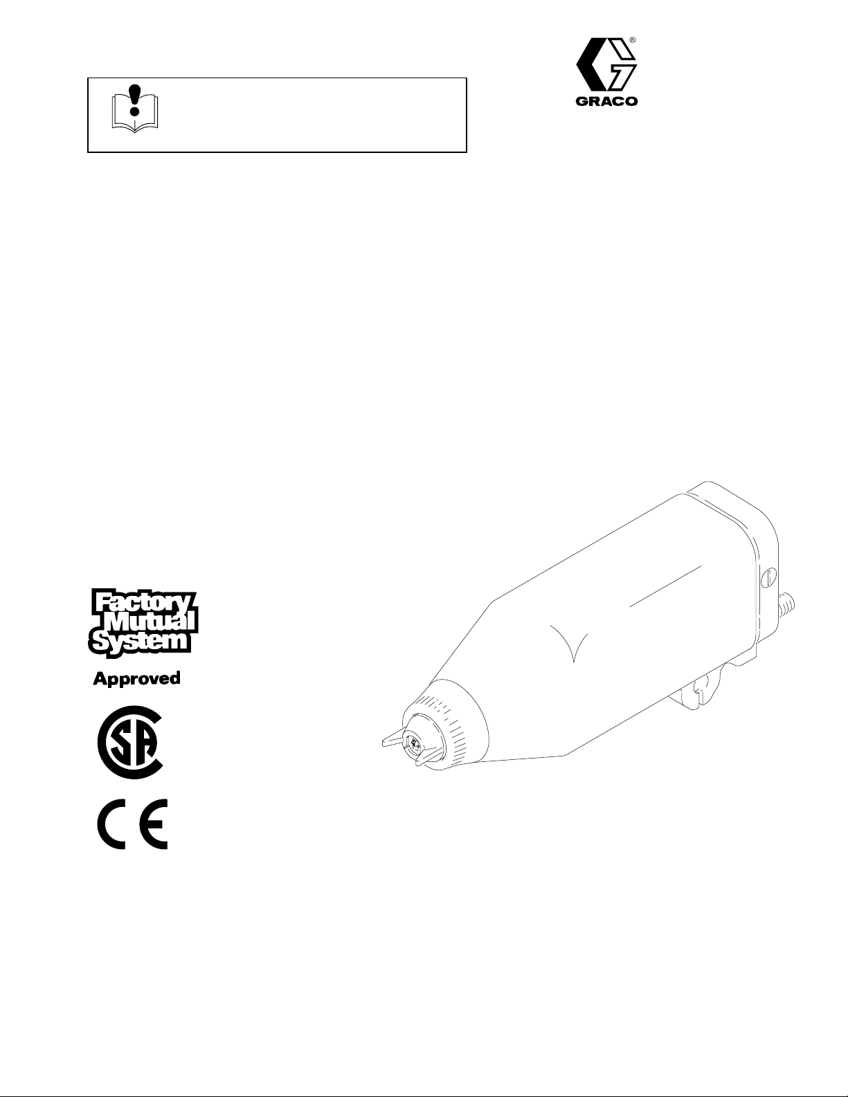
AUTOMATIC ELECTROSTATIC
Model PRO AA5500sc
Air-Assisted Airless Spray Gun
100 psi (7 bar, 0.7 MPa) Maximum Working Air Pressure
3000 psi (207 bar, 20.7 MPa) Maximum Working Fluid Pressure
For use with Class I, Group D paint spray materials
Part No. 236688, Series B
Complete Spray Gun: includes spray gun, shroud,
manifold, and mounting bracket
U.S. PATENT NO. 4,290,091; 4,219,865; 4,497,447; 4,462,061; 4,660,774;
5,063,350; 5,080,289; 5,289,977
Patented 1986, 1987 Canada
Brevete 1986, 1987
U.K. PATENT NO. 2,147,158; 2,142,559B; 2,140,327–B
Other Foreign Patents Pending
Rev. J
03228
NOTE: Any modification of genuine Graco parts or
replacement of parts with non-Graco parts will void
agency approvals.
GRACO INC. P.O. BOX 1441 MINNEAPOLIS, MN 55440–1441
COPYRIGHT 1994, GRACO INC.
Graco Inc. is registered to I.S. EN ISO 9001
Page 2
WARNING
FIRE, EXPLOSION, AND ELECTRIC SHOCK HAZARD
Improper grounding, poor air ventilation, open flames, or sparks can cause a hazardous condition and
result in a fire, explosion, or electric shock.
Electrostatic equipment must be used only by trained, qualified personnel who understand the
requirements stated in this instruction manual.
Ground the equipment, personnel in or close to the spray area, the object being sprayed, and all
other electrically conductive objects in the spray area. See Ground the System on page 13.
Check the spray gun resistance daily. See Test Gun Resistance, page 28.
If there is any static sparking while using the equipment, stop spraying immediately. Identify and
correct the problem.
Provide fresh air ventilation to avoid the buildup of flammable or toxic vapors. Interlock the gun
turbine air supply to prevent operation of the power supply unless the ventilating fans are on. See
Ventilate the Spray Booth on page 7.
When cleaning, flushing, or purging electrostatic equipment, use solvents that comply with your
local regulations. For countries following the U.S. National Fire Protection Association (NFPA) 33
requirements, use solvents with a flash point higher than 100 F (38 C) or a solvent normally
used in spray operations. For European Countries complying with EN 50053, use solvents with a
flash point as high as possible and higher than the ambient temperatures.
Use only non-sparking tools to clean residue from the booth and hangers.
Do not flush the system with the gun electrostatics turned on.
Do not turn on the gun electrostatics until all solvent is removed from the system.
Extinguish all open flames or pilot lights in the spray area.
Keep the spray area free of debris, including solvent, rags, and gasoline.
Do not store any flammable fluids in the spray area.
Do not turn on or off any light switch in the spray area while operating or if fumes are present.
Do not smoke in the spray area.
Do not operate a gasoline engine in the spray area.
TOXIC FLUID HAZARD
Hazardous fluids or toxic fumes can cause a serious injury or death if splashed in the eyes or on the
skin, swallowed, or inhaled.
Know the specific hazards of the fluid you are using. Read the fluid manufacturer’s warnings.
Store hazardous fluid in an approved container. Dispose of the hazardous fluid according to all
local, state, and national guidelines.
Wear appropriate protective clothing, gloves, eyewear, and respirator.
2 308387
Page 3
WARNING
INJECTION HAZARD
Spray from the gun, hose leaks, or ruptured components can inject fluid into your body and cause an
extremely serious injury, including the need for amputation. Splashing fluid in the eyes or on the skin
can also cause a serious injury.
Fluid injected into the skin might look like just a cut, but it is a serious injury. Get immediate medi-
cal attention.
Do not point the spray gun at anyone or any part of the body.
Do not put hand or fingers over the spray tip.
Do not stop or deflect fluid leaks with your hand, body, glove, or rag.
Do not “blow back” fluid; this is not an air spray system.
Always have the tip guard on the spray gun when spraying.
Follow the Pressure Relief Procedure on page 16 whenever you: are instructed to relieve pres-
sure; stop spraying; clean, check, or service the equipment; and install or clean the spray tip.
Tighten all the fluid connections before operating the equipment.
Check the hoses, tubes and couplings daily. Replace worn, damaged, or loose parts immediately.
Permanently coupled hoses cannot be repaired; replace the entire hose.
INSTRUCTIONS
EQUIPMENT MISUSE HAZARD
Equipment misuse can cause the equipment to rupture, malfunction, or start unexpectedly and result
in a serious injury.
This equipment is for professional use only.
Read all the instruction manuals, tags, and labels before operating the equipment.
Use the equipment only for its intended purpose. If you are uncertain about usage, call your Graco
distributor.
Do not alter or modify this equipment. Use only genuine Graco parts and accessories.
Check the equipment daily. Repair or replace worn or damaged parts immediately.
Do not exceed the maximum working pressure of the lowest rated system component. This equip-
ment has a 100 psi (7 bar, 0.7 MPa) maximum working air pressure and 3000 psi (207 bar,
20.7 MPa) maximum working fluid pressure.
Use fluids that are compatible with the equipment wetted parts. See the Technical Data section of
all the equipment manuals. Read the fluid manufacturer’s warnings.
Route the hoses away from traffic areas, sharp edges, moving parts, and hot surfaces. Do not
expose Graco hoses to temperatures above 180F (82C) or below –40F (–40C).
Do not use the hoses to pull equipment.
Wear hearing protection when operating this equipment.
Comply with all applicable local, state, and national fire, electrical, and other safety regulations.
308387 3
Page 4

Table of Contents
Warnings 2. . . . . . . . . . . . . . . . . . . . . . . . . . . . . . . . . . . . .
Symbols 4. . . . . . . . . . . . . . . . . . . . . . . . . . . . . . . . . . . . . .
Introduction 5. . . . . . . . . . . . . . . . . . . . . . . . . . . . . . . . . .
How the PRO AA5500sc Electrostatic Air-Assisted
Airless Spray Gun Operates 5. . . . . . . . . . . . . . . . . . . . .
Operating the Spray Function 5. . . . . . . . . . . . . . . . . . . .
Operating the Electrostatics 5. . . . . . . . . . . . . . . . . . . . . .
Switching to the Higher or Lower kV Setting 5. . . . . . . .
Gun Features and Options 5. . . . . . . . . . . . . . . . . . . . . . .
Installation 7. . . . . . . . . . . . . . . . . . . . . . . . . . . . . . . . . . .
Installing the System 7. . . . . . . . . . . . . . . . . . . . . . . . . . . .
Warning Signs 7. . . . . . . . . . . . . . . . . . . . . . . . . . . . . . . . .
Ventilate the Spray Booth 7. . . . . . . . . . . . . . . . . . . . . . . .
Install the Air Line Accessories 9. . . . . . . . . . . . . . . . . . .
Fluid Line Accessories 10. . . . . . . . . . . . . . . . . . . . . . . . .
Install the Gun and Mounting Bracket 10. . . . . . . . . . . .
Connect the Air and Fluid Lines
to the Gun Manifold 11. . . . . . . . . . . . . . . . . . . . . . . . . . . .
Optional Fiber Optic Cable Connection 12. . . . . . . . . . .
Optional Fiber Optic Lens Kit Installation 12. . . . . . . . .
Ground the System 13. . . . . . . . . . . . . . . . . . . . . . . . . . . .
Check the Electrical Grounding 14. . . . . . . . . . . . . . . . . .
Install the Fabric Cover 15. . . . . . . . . . . . . . . . . . . . . . . . .
Service 30. . . . . . . . . . . . . . . . . . . . . . . . . . . . . . . . . . . . . .
Tools Included with the Gun 30. . . . . . . . . . . . . . . . . . . . .
Prepare the Gun for Service 30. . . . . . . . . . . . . . . . . . . .
Tip Guard, Air Cap, Spray Tip, or Seat
Housing Replacement 32. . . . . . . . . . . . . . . . . . . . . . . . . .
Electrode Replacement 33. . . . . . . . . . . . . . . . . . . . . . . .
Fluid Tube Removal and Replacement 34. . . . . . . . . . .
Fluid Filter Replacement 34. . . . . . . . . . . . . . . . . . . . . . .
Piston Repair 35. . . . . . . . . . . . . . . . . . . . . . . . . . . . . . . . .
Barrel Removal 36. . . . . . . . . . . . . . . . . . . . . . . . . . . . . . .
Fluid Packing Adjustment 37. . . . . . . . . . . . . . . . . . . . . . .
Fluid Needle Assembly Removal 37. . . . . . . . . . . . . . . .
Power Supply Removal and Replacement 38. . . . . . . .
Lower Voltage Setting Adjustment 38. . . . . . . . . . . . . . .
Turbine Alternator Removal and Replacement 39. . . . .
Barrel Installation 40. . . . . . . . . . . . . . . . . . . . . . . . . . . . . .
Install the Gun onto the Manifold
and Mounting Bracket 41. . . . . . . . . . . . . . . . . . . . . . . . . .
Spray Gun Parts 42. . . . . . . . . . . . . . . . . . . . . . . . . . . . .
Manifold Parts 44. . . . . . . . . . . . . . . . . . . . . . . . . . . . . . .
Accessories 46. . . . . . . . . . . . . . . . . . . . . . . . . . . . . . . . .
Spray Tip Selection Chart 48. . . . . . . . . . . . . . . . . . . . .
Operation 16. . . . . . . . . . . . . . . . . . . . . . . . . . . . . . . . . . . .
Pressure Relief Procedure 16. . . . . . . . . . . . . . . . . . . . . .
Operating Checklist 16. . . . . . . . . . . . . . . . . . . . . . . . . . . .
Selecting a Spray Tip 17. . . . . . . . . . . . . . . . . . . . . . . . . .
Installing the Spray Tip 17. . . . . . . . . . . . . . . . . . . . . . . . .
Setting the Atomization Fluid Pressure 18. . . . . . . . . . .
Activating and Adjusting the Electrostatics 19. . . . . . . .
Activating the kV Switch 19. . . . . . . . . . . . . . . . . . . . . . . .
Spraying 19. . . . . . . . . . . . . . . . . . . . . . . . . . . . . . . . . . . . .
Triggering the Fluid Alone 20. . . . . . . . . . . . . . . . . . . . . .
Shutdown 20. . . . . . . . . . . . . . . . . . . . . . . . . . . . . . . . . . . .
Maintenance 20. . . . . . . . . . . . . . . . . . . . . . . . . . . . . . . . .
Daily Care and Cleaning 20. . . . . . . . . . . . . . . . . . . . . . . .
Flush the Spray Gun 21. . . . . . . . . . . . . . . . . . . . . . . . . . .
Clean the Spray Gun 22. . . . . . . . . . . . . . . . . . . . . . . . . .
Check for Fluid Leakage 24. . . . . . . . . . . . . . . . . . . . . . .
Troubleshooting 25. . . . . . . . . . . . . . . . . . . . . . . . . . . . .
Spray Pattern Troubleshooting 25. . . . . . . . . . . . . . . . . .
Gun Operation Troubleshooting 26. . . . . . . . . . . . . . . . .
Electrical Troubleshooting 27. . . . . . . . . . . . . . . . . . . . . .
Electrical Tests 28. . . . . . . . . . . . . . . . . . . . . . . . . . . . . . .
Test Gun Resistance 28. . . . . . . . . . . . . . . . . . . . . . . . . . .
Test Power Supply Resistance 28. . . . . . . . . . . . . . . . . .
Test Barrel Resistance 29. . . . . . . . . . . . . . . . . . . . . . . . .
Technical Data 49. . . . . . . . . . . . . . . . . . . . . . . . . . . . . . .
The Graco Warranty and Disclaimers 52. . . . . . . . . .
Graco Phone Number 52. . . . . . . . . . . . . . . . . . . . . . . .
Symbols
Warning Symbol
WARNING
This symbol alerts you to the possibility of serious
injury or death if you do not follow the instructions.
Caution Symbol
CAUTION
This symbol alerts you to the possibility of damage to
or destruction of equipment if you do not follow the
corresponding instructions.
4 308387
Page 5

Introduction
How the PRO AA5500sc Electrostatic
Air-Assisted Airless Spray Gun Operates
(Refer to page 6)
WARNING
INJECTION HAZARD
This is not an air spray gun. To reduce
the risk of an injection injury, read and
follow the Warnings on pages 2 and 3
and throughout the text of this instruction manual.
The air-assisted airless spray gun combines airless
and air spraying concepts. The spray tip (B) shapes
the fluid into a fan pattern, as does a conventional
airless spray tip. Air from the air cap (A) further atomizes the fluid and completes the atomization of the
paint tails into the pattern to produce a more uniform
pattern. The ability of the PRO AA5500 Electrostatic
Spray Gun to spray at higher fluid pressures provides
the additional power needed to atomize higher solids
materials.
Operating the Spray Function
Applying a minimum of 50 psi (3.5 bar, 0.35 MPa) air
pressure to the gun manifold’s cylinder air fitting (which
is marked “CYL”, see page 6) will retract the gun
piston, which opens the air valves and a short time
later opens the fluid needle. This provides the proper
air lead and lag when triggering the gun. A spring
returns the piston when the cylinder air is shut off.
Operating the Electrostatics
To operate the electrostatics, air pressure is applied to
the gun manifold’s turbine air fitting (which is marked
“TA”, see page 6) through a Graco electrically conductive air hose. The air enters the manifold and is
directed to the inlet of the power supply turbine (H).
The air spins the turbine, which then provides electrical
power to the internal high voltage power supply (J).
The fluid is charged by the spray gun electrode (K).
The charged fluid is attracted to the nearest grounded
object, wrapping around and evenly coating all surfaces.
The turbine air is exhausted into the shroud (E) and
out the back of the manifold through the fitting marked
“EXH”. The exhaust air helps keep contaminants out
and helps keep the gun clean.
Switching to the Higher or Lower
kV Setting
The gun’s full high voltage setting is 85 kilovolts. The
gun’s spraying voltage can be reduced by switching to
the low voltage setting for spraying in areas where too
much electrostatic wrap is not desirable. Applying a
minimum of 50 psi (3.5 bar, 0.35 MPa) air pressure to
the kV switch air inlet (which is marked “KV”, see page
6) will activate it and switch to the lower voltage
setting. The lower voltage is factory set to 60 kilovolts
at zero microamperes. This setting can be adjusted
from 45 to 80 kilovolts, as instructed on page 38. The
solenoid valve used to activate the kV switch must
bleed the air out of the line for the switch to draw back
to the higher voltage setting.
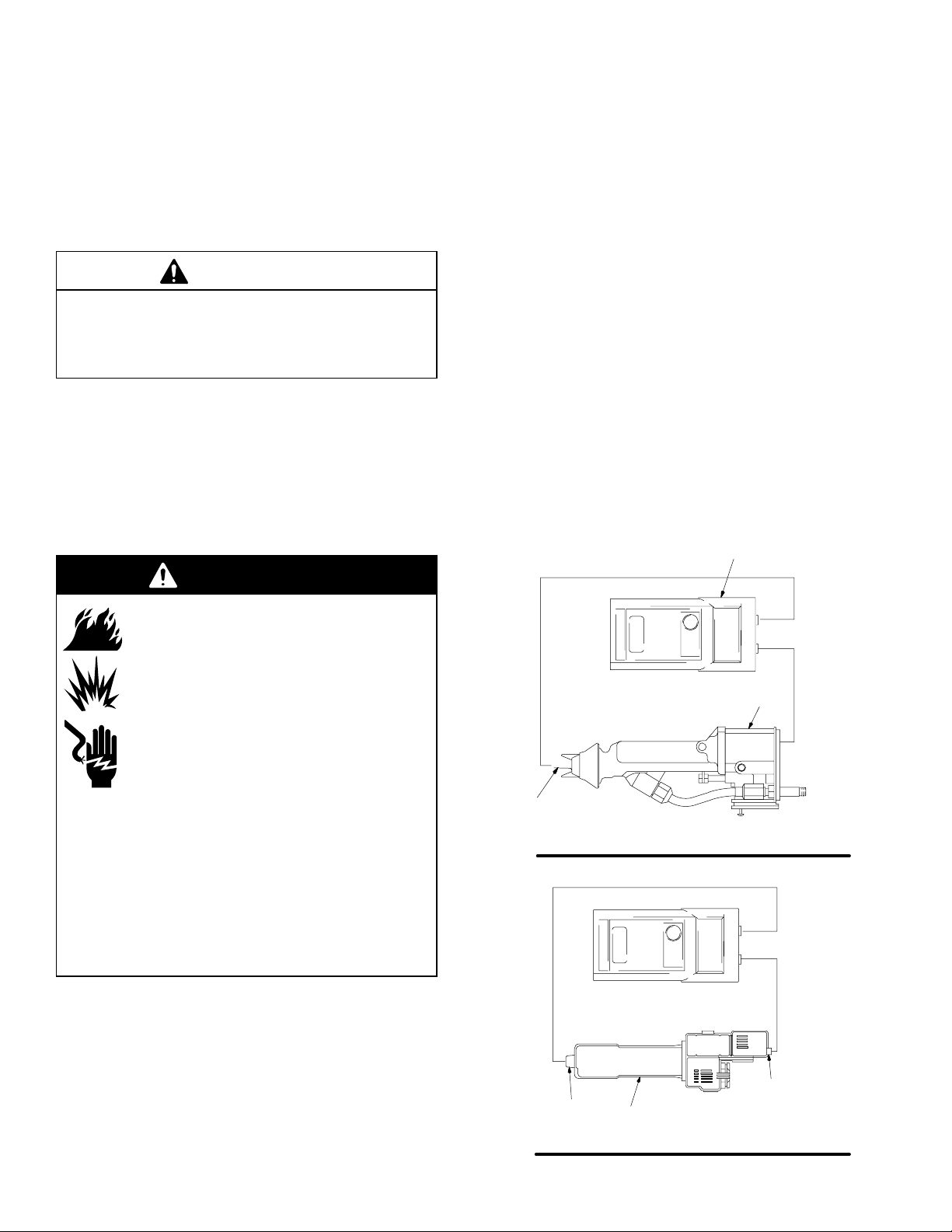
Gun Features and Options
The gun is designed for use with a reciprocator,
and it can be directly mounted to a one-half inch
rod. With additional brackets, the gun can be
mounted for robotic applications.
The gun is designed for quick-disconnect, which
enables the operator to quickly remove the spray
gun without disconnecting the air lines to the gun.
The gun functions are activated from a separate
controller that sends the appropriate signal to the
actuating solenoids (S). See Fig. 1, page 8.
An optional fiber optic readout system can be
installed to monitor the gun’s spraying voltage. A
fiber optic cable (KK) connected to the gun manifold carries the signal from the gun to a remote ES
(electrostatic) display module. See Fig. 2, page 8.
An ES Display Module (GG), P/N 224117, is available and will display the gun’s spraying voltage and
current. A battery operated ES Display Module
(FF), P/N 189762, is also available; it displays the
gun’s spraying voltage only.
308387 5
Page 6
Introduction
G
C
AB D E F
03228
TA
CYL
A1
P1
KV
F.O.
A2
EXH
P2
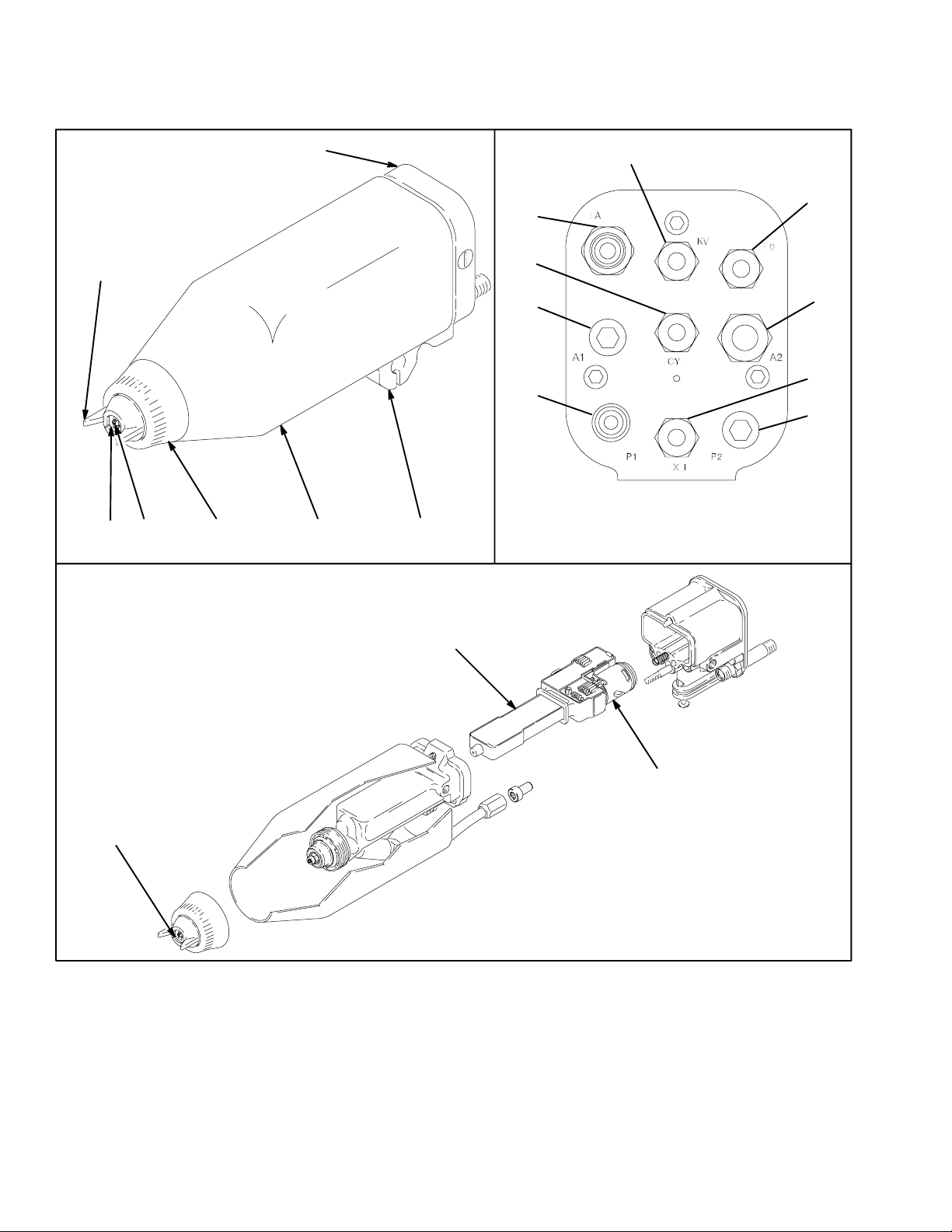
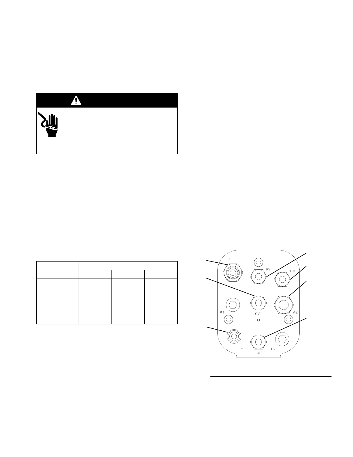
Manifold Back View
03616
K
KEY
A Air Cap (orange color)
B Spray Tip (orange color)
C T ip Guard (orange color)
D Retaining Nut
E Shroud
F Mounting Bracket
G Manifold
H Turbine
J Power Supply
K Electrode
6 308387
J
H
04799
Manifold Markings
A1 not used
A2 Atomization Air Inlet Fitting
CYL Cylinder Air Inlet Fitting
EXH Shroud Exhaust Outlet Fitting
F.O. Fiber Optic Fitting
KV kV Switch Air Inlet
P1 Fluid Supply Inlet Fitting
P2 not used
TA Turbine Air Inlet Fitting
Page 7
Installation
Installing the System
WARNING
FIRE, EXPLOSION, AND
ELECTRIC SHOCK HAZARD
Installing and servicing this equipment
requires access to parts which may
cause electric shock or other serious
injury if work is not performed properly.
Do not install or service this equip-
ment unless you are trained and
qualified.
Be sure your installation complies with National,
State and Local codes for the installation of
electrical apparatus in a Class I, Group D
Hazardous Location.
Comply with all applicable local, state, and
national fire, electrical, and other safety regulations.
Fig. 1, page 8, shows a typical Model PRO AA5500sc
system. Fig. 2 shows some possible system options.
Accessories are available from your Graco representative. Refer to the Product Data Sheet for the gun,
Form No. 305624. If you supply your own accessories,
be sure they are adequately sized and pressure rated
for your system.
For assistance in designing a system that is customized for your application, contact your Graco distributor.
Warning Signs
Mount the warning signs in the spray area where they
can easily be seen and read by all operators. An
English Warning Sign is provided with the gun. Additional signs are available at no charge.
Part No. Description
180060 Warning Sign (English)
Ventilate the Spray Booth
WARNING
FLAMMABLE OR TOXIC
VAPOR HAZARD
Provide fresh air ventilation to avoid the
buildup of flammable or toxic vapors. Do
not operate the gun unless ventilation
fans are operating.
Electrically interlock the gun turbine air supply line with
the ventilators to prevent operation of the electrostatic
power supply unless ventilating fans are on.
Check and follow all local, state, and national codes
regarding air exhaust velocity requirements. High
velocity air exhaust will decrease the operating efficiency of the electrostatic system. The minimum
allowable air exhaust velocity is 60 feet/minute (19
linear meters/minute).
308387 7
Page 8
Installation
R
*A
A*R
Non-Hazardous Area Hazardous Area
BASIC SYSTEM
AA*
X
S
CC
S
Y
S
Z
BB*
TA
**
KV
**
A2
**
CYL
**
P1
**
S
U*
Q
FLUID IN-P1
V
W
G*
F
H
J*
K
To FLUID IN-P1 at gun
Fig. 1
DD
EE
FF
B
*C *T D E
P
*M
Non-Hazardous Area Hazardous Area
GG HH
kV
mA
kV
JJ*
KK
L*
N
SYSTEM OPTIONS
Spraying Voltage
Display Module
X
F.O.
**
Fig. 2
8 308387
04802
Page 9
KEY–Fig. 1 a n d 2
Installation
A* Bleed-type Master Air Valve
B Air Line Filter
C* Pump Air Regulator
D Air Line Lubricator
E Pump Runaway Valve
F Pump
G* Pump Ground Wire
H Fluid Shut-off Valve
J* Fluid Pressure Regulator
K Pressure Gauge
L* Grounded Fluid Hose with spring guards
M* Fluid Drain Valve
N Fluid Filter
P Pump Air Line
Q Gun Air Pressure Regulator
R Main Air Line
S Solenoid Valve, requires quick-exhaust port*
T* Bleed-type Air Shut-off Valve
U* True Earth Ground
V Fluid Hose, 1/4–18 npsm gun fluid inlet
W Mounting Bracket for 1/2 inch (127 mm) rod, P/N 189581
X PRO AA5500sc Spray Gun, P/N 236688
Install the Air Line Accessories
WARNING
Y Atomizing Air Hose, 3/8 inch (9.5 mm) O.D.
Z Cylinder Air Hose, 1/4 inch (6.4 mm) O.D.
AA*Ground Wire on Graco Electrically Conductive Air Hose
BB*Graco Electrically Conductive Air Hose (Turbine Air Hose),
See page 11 for part numbers
CC kV Switch Air Hose, 1/4 inch (6.4 mm) O.D., plug the gun fitting if
it is not used
DD 24 Volt Power Supply, P/N 235301
EE 4–20 mA Outputs
FF kV Only ES Display Module (battery operated), P/N 189762
GG Full Feature ES Display Module, P/N 224117
HH Fiber Optic Cable, P/N 224680 to 224686
JJ Bulkhead, P/N 189870
KK Fiber Optic Cable, P/N 224670 to 224676
The turbine air supply must be interlocked with the spray booth
ventilation fans.
A maximum of two splices with a total of 108 feet (32.94 m) of
cable can be used. For the strongest light signals, use a minimum
number of bulkhead splices.
* Equipment required for safe operation of system. Must be pur-
chased separately.
** See page 11 for a description of the manifold connections.
3. Install an air regulator (Q) on each of the air supply
lines (BB, CC. Y. Z) to control the air pressure to
the gun.
COMPONENT RUPTURE HAZARD
To reduce the risk of serious injury
due to component rupture:
The pump pressure must be limited by the
pump air regulator (C). See Fig. 1, page 8.
Do not rely on the gun fluid regulator (J) to
limit the fluid pressure to the gun.
The fluid supply pump must be prevented
from producing a fluid pressure greater than
the 3000 psi (207 bar, 20.7 MPa) Maximum
Working Pressure of the spray gun. For example, the air supply pressure to a 30:1
pump must not exceed 100 psi (7 bar, 0.7
MPa).
Be sure that all spray equipment and acces-
sories added to the spray system are properly rated to withstand the maximum working
pressure of your system.
1. Install a bleed-type master air valve (A) on the
main air supply line (R) to shut off all the air to the
gun. See Fig. 1, page 8.
2. To ensure a dry, clean air supply to the gun, install
an air line filter and an air and water separator on
the air lines. Dirt and moisture can ruin the appearance of your finished workpiece and can cause the
gun to malfunction.
4. Install a solenoid valve (S) on the atomization air
line (Y) to actuate the gun and shut off the
atomization air to the gun. The solenoid valve must
have a quick exhaust port.
5. Install a bleed-type air shut-off valve (T) on the
pump air line to shut off air to the pump. Install an
additional bleed-type valve on each pump air
supply line to relieve air trapped between this valve
and the pump after the air regulator is shut off.
WARNING
INJECTION HAZARD
Trapped air can cause the pump to cycle
or the gun to spray unexpectedly, which
could result in a serious injury, including
injecting fluid through the skin. The solenoid valves
(S) must have a quick-exhaust port so trapped air will
be relieved between the valve and the gun when the
solenoids are shut off. The bleed-type air shut-off
valve (T) is required on the pump air line (P) so
trapped air will be relieved between the valve and the
pump after the valves or regulator are closed.
308387 9
Page 10
Installation
Fluid Line Accessories
1. Install a fluid filter (N) and drain valve (M) at the
pump outlet. See Fig. 1, page 8. Filtering the fluid
will help remove coarse particles and sediment
that could clog the spray tip.
WARNING
INJECTION HAZARD
The fluid drain valve (M) is required in
your system to help relieve fluid pres-
sure in the displacement pump, hose
and gun; triggering the gun to relieve pressure may
not be sufficient. Install a drain valve close to the
pump’s fluid outlet. The drain valve reduces the risk
of serious injury, including fluid injection and
splashing in the eyes or on the skin.
2. Install a fluid regulator (J) on the fluid line to control fluid pressure to the gun.
Install the Gun and Mounting Bracket
2.775 in .
(70.5 mm)
PRO AA5500sc Gun
103
0.50 in.
(12.7 mm)
rod
103
Fig. 3
NOTE: For added positioning reliability, the mounting
bracket (MM) has an 1/8 in. (3.2 mm) slot where a
locating pin (NN–not included) can be inserted through
the mounting rod (PP). See Fig. 4.
9.32 in.
(236.7 mm)
03619
NN
MM
1. Loosen the mounting bracket’s two square head
bolts (103) and slide the mounting bracket onto a
0.50 in. (12.7 mm) mounting rod. See Fig. 3.
2. Position the gun and tighten the two bolts (103)
securely.
Fig. 4
PP
03460
10 308387
Page 11
Installation
Connect the Air and Fluid Lines
to the Gun Manifold
See Fig. 1 and 2, page 8, for a schematic of air and
fluid connections. Connect the air and fluid lines to the
gun manifold as instructed at right.
Graco Electrically Conductive Air Hose
WARNING
ELECTRIC SHOCK HAZARD
To reduce the risk of electric shock or
other serious injury, the air supply hose
must be electrically connected to a true
earth ground. Use Only Graco Electrically Con-
ductive Air Supply Hose.
Connect the Graco electrically conductive air hose
(BB) to the gun turbine air inlet and connect the hose
ground wire (AA) to a true earth ground. See Fig. 1,
page 8. Check the electrical grounding of the gun as
instructed on page 14.
NOTE: The hose and the gun have special left-hand
threads to prevent connecting another type of air hose
to the gun turbine air inlet.
Graco Electrically Conductive Air Hose
Required for gun operation.
100 psi (7 bar, 0.7 MPa) Maximum Working Pressure
0.315 in. (8 mm) ID; 1/4 npsm(f) x 1/4 npsm(f) left-hand
Part No.
Length Black Hose Grey Hose Red Hose
6 ft. (1.8 m)
15 ft. (4.6 m)
25 ft. (7.6 m)
36 ft. (11.0 m)
50 ft. (15.2 m)
75 ft. (23.0 m)
100 ft. (30. 5 m)
Black Hose: standard hose, semi-conductive nylon core,
urethane outer
220444
218100
218101
218102
218103
220119
220120
223068
223069
223070
223071
223072
223073
223074
235068
235069
235070
235071
235072
235073
235074
Fluid Line
Before connecting the fluid line to the gun, blow it out
with air and flush it with solvent. Use solvent that is
compatible with the fluid being sprayed.
Manifold Connections (See Fig. 5)
A2 Atomization Air Inlet Fitting
Connect a 3/8 inch O.D. tube between the fitting and
the air supply.
CYL Cylinder Air Inlet Fitting
Connect a 1/4 inch O.D. tube between this fitting and
the solenoid. For quicker trigger response, use the
shortest hose length possible.
EXH Shroud Exhaust Outlet Fitting
Connect a 1/4 inch O.D. x 4 foot (1.22 m) long tube to
the fitting.
F.O. Fiber Optic Fitting (Optional)
Connect the Graco Fiber Optic Cable as instructed on
page 12.
KV kV Switch Air Inlet Fitting
Connect a 1/4 inch O.D. tube between the fitting and
the air solenoid.
P1 Fluid Supply Inlet Fitting
Connect a 1/4 inch npsm swivel fitting between the
fitting and the fluid supply.
TA Turbine Air Inlet Fitting
Connect the Graco Electrically Conductive Air Hose
between this fitting (left-hand thread) and the solenoid.
Connect the air hose ground wire to a true earth
ground.
KV
TA
CYL
F.O.
A2
EXH
P1
Grey Hose: more flexible (less durable) than black hose,
modified semi-conductive polyamide core, urethane cover
Red Hose: conductive SST wire braid for grounding, polyurethane tube and cover
Fig. 5
Manifold Back View
03616
308387 11
Page 12
Installation
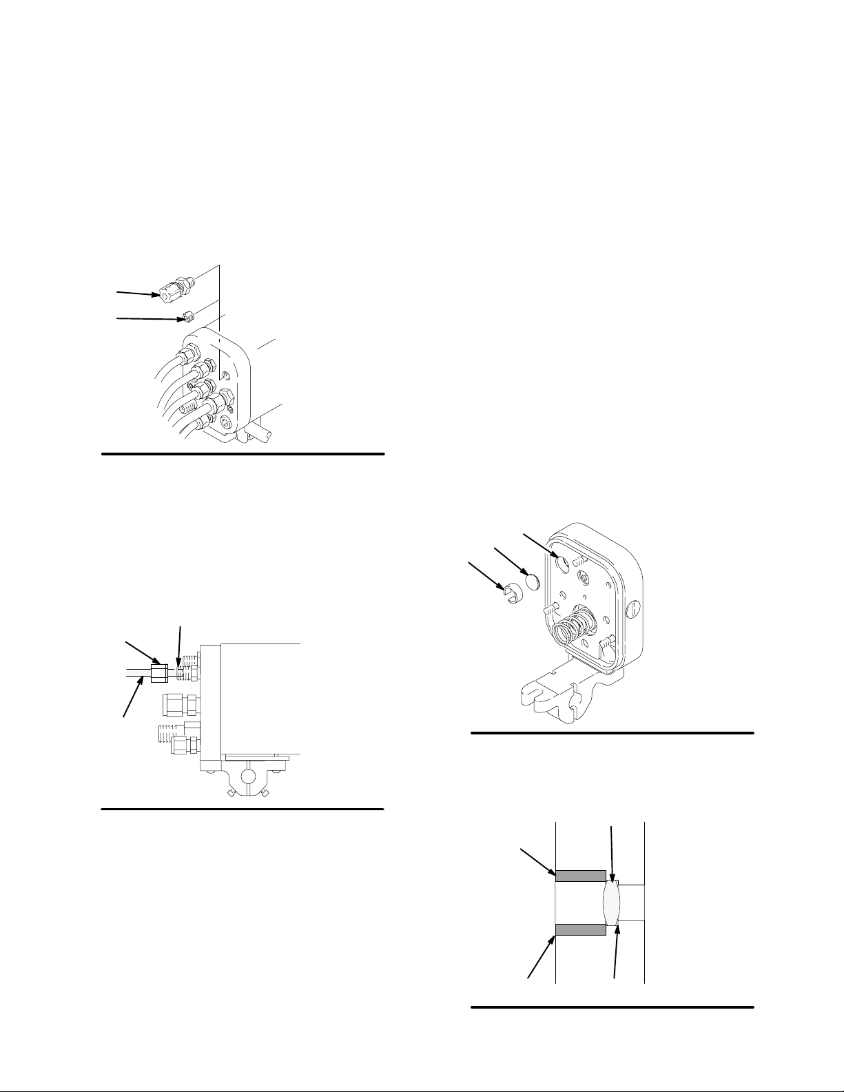
Optional Fiber Optic Cable Connection
An optional fiber optic fitting (37) is shipped unassembled with the gun. If an ES (kV) display module is
used, install the fitting in the manifold. See Fig. 2, page
8, for a schematic of the fiber optic connections.
1. Remove the 1/8 npt plug (115) from the manifold’s
fiber optic port, and install the black fiber optic
fitting (37). See Fig. 6.
37
115
Fig. 6
2. Remove the nut (QQ) from the fiber optic fitting
(37), and slide the nut over the end of the fiber
optic cable (RR). See Fig. 7.
3. Insert the cable (RR) into the fitting (37), and push
the cable in until it bottoms out. Tighten the nut
(QQ) to secure the cable.
03620
Optional Fiber Optic Lens Kit Installation
NOTE: The fiber optic lens kit is not included with the
gun. Order it separately; the part number is 236852.
1. Remove the gun from the manifold as instructed
on page 30.
2. Make sure the lens (TT) is clean. Push the lens
into the counterbore (VV) in the manifold fiber optic
port (SS). See Fig. 8 and 9.
3. Press the lens retainer (UU) into the manifold fiber
optic port (SS) until it is flush with the manifold
surface.
4. Assemble the gun to the manifold as instructed on
page 41.
SS
TT
UU
37
QQ
RR
Fig. 7
4. If you have two bulkhead splices in your system, it
is recommended that you install the fiber optic lens
kit, as described at right.
NOTE: Most of the fiber optic light transmission loss
occurs at the bulkhead splices. For the strongest light
signals, use a minimum number of bulkhead splices. A
maximum of two splices, with a total of 108 feet (32.94
m) of cable, is recommended.
5. See manual 308265 to install a Graco ES Display
Module.
12 308387
03509A
Fig. 8
Fig. 9
UU
TT
VVSS
04798
04485
Page 13
Installation
Ground the System
WARNING
FIRE, EXPLOSION, AND
ELECTRIC SHOCK HAZARD
When operating the electrostatic gun,
any ungrounded objects in the spray
area (such as people, containers, tools,
etc.) can become electrically charged.
Improper grounding can result in static
sparking, which can cause a fire, explosion, or electric shock. Follow the
grounding instructions below.
The following grounding instructions are minimum
requirements for a basic electrostatic system. Your
system may include other equipment or objects which
must be grounded. Check your local electrical code for
detailed grounding instructions. Your system must be
connected to a true earth ground.
1. Pump: ground the pump by connecting a ground
wire and clamp as described in your separate
pump instruction manual.
3. Electrostatic Air Spray Gun: ground the gun by
connecting the Graco Electrically Conductive Air
Hose to the turbine air inlet and connecting the air
hose ground wire to a true earth ground. Check
the electrical grounding of the gun as instructed on
page 14.
4. All air and fluid lines must be properly grounded.
5. All electric cables must be properly grounded.
6. All persons entering the spray area: their shoes
must have conductive soles, such as leather, or
personal grounding straps must be worn. Rubber
or plastic soles are not conductive.
7. Object being sprayed: keep the workpiece hangers
clean and grounded at all times. Contact points
must be sharp points or knife edges.
8. The floor of the spray area: must be electrically
conductive and grounded. Do not cover the floor
with cardboard or any non-conductive material
which would interrupt grounding continuity.
9. Flammable liquids in the spray area: must be kept
in approved, grounded containers. Do not store
more than the quantity needed for one shift.
2. Air compressors and hydraulic power supplies:
ground the equipment according to the manufacturer’s recommendations.
10. All electrically conductive objects or devices in the
spray area: including fluid containers and wash
cans, must be properly grounded.
308387 13
Page 14
Installation
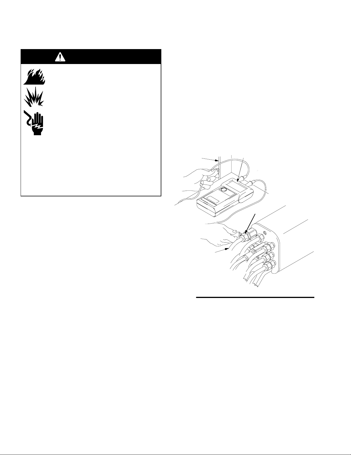
Check the Electrical Grounding (See Fig. 10)
WARNING
FIRE, EXPLOSION, AND
ELECTRIC SHOCK HAZARD
Megohmmeter P/N 241079 (WW-see
Fig. 10) is not approved for use in a
hazardous area. To reduce the risk of
sparking, do not use the megohmmeter
to check electrical grounding unless:
The gun has been removed from the
hazardous area;
Or all spraying devices in the hazardous area
are turned off, ventilation fans in the hazardous
area are operating, and there are no flammable
vapors in the area (such as open solvent containers or fumes from spraying).
Failure to follow this warning could cause fire,
explosion, electric shock and result in serious injury
and property damage.
a. If using a black or grey turbine air hose, use a
megohmmeter (WW) to measure the
resistance. Use an applied voltage of 500
minimum to 1000 volts maximum. Resistance
should not exceed 2 megohms.
b. If you are using a red turbine air hose, use an
ohmmeter to measure the resistance.
Resistance should not exceed 100 ohms.
5. If the resistance is greater than the maximum
reading specified above for your hose, check the
tightness of the ground connections and be sure
the turbine air hose ground wire is connected to a
true earth ground. If the resistance is still too high,
replace the turbine air hose.
N
WW
1. Have a qualified electrician check the electrical
grounding continuity of the spray gun and turbine
air hose.
2. Make sure the turbine air hose (B) is connected
and the hose ground wire is connected to a true
earth ground.
3. The air and fluid supplies to the gun must be
turned off, and the fluid hose must not have any
fluid in it when checking the continuity.
4. Measure the resistance between the turbine air
inlet fitting (TA) and a true earth ground (N).
TA
B
TI0376
Fig. 10
14 308387
Page 15
Installation
Install the Fabric Cover
1. Install a fabric cover (XX) over the front of the gun
and slide it back to cover the exposed tubing and
hoses at the back of the manifold. See Fig. 11.
XX
YY
Fig. 11
2. Route the exhaust tube (YY) outside the cover.
This enables you to monitor the exhaust tube for
the presence of any paint or solvent. See Check
for Fluid Leakage on page 24. Strap down the
exhaust tube to prevent it from moving around.
YY
Manifold Back View
03623
03622
308387 15
Page 16
Operation
Pressure Relief Procedure
WARNING
INJECTION HAZARD
The system pressure must be manually
relieved to prevent the system from
starting or spraying accidentally. Fluid
under high pressure can be injected through the
skin and cause serious injury. To reduce the risk of
an injury from injection, splashing fluid, or electric
shock, follow the Pressure Relief Procedure
whenever you:
are instructed to relieve the pressure,
stop spraying,
check or service any of the system equipment,
or install or clean the spray tip.
1. Turn off all the air to the spray gun except the
cylinder air, which triggers the gun.
2. Turn off the fluid supply to the gun.
3. Trigger the gun into a grounded metal waste
container to relieve fluid pressure.
4. Open the pump drain valve (required in system) to
help relieve fluid pressure in the displacement
pump. In addition, open the drain valve connected
to the fluid pressure gauge (in a system with fluid
regulation) to help relieve fluid pressure in the
hose and gun. Triggering the gun to relieve pressure may not be sufficient. Have a container ready
to catch the drainage.
5. Leave the pump drain valve open until you are
ready to spray again.
6. Turn off the main air supply by closing the bleedtype master air valve on the main air supply line.
Leave the valve closed until you are ready to spray
again.
7. If you suspect that the spray tip or hose is completely clogged or that pressure has not been fully
relieved after following the steps above, very
slowly loosen the hose end coupling and relieve
pressure gradually, then loosen completely. Now
clear the tip or hose obstruction.
Operating Checklist
WARNING
INJECTION HAZARD
The wallet sized warning card 179960,
provided with the gun, should be avail-
able and easily accessible at all times for
anyone operating or servicing this equipment. The
card contains important information on what to do if
a fluid injection injury occurs. Additional cards are
available at no charge from Graco.
Check the following list daily, before starting to operate
the system, to help ensure safe, efficient operation.
____ 1. All the operators are properly trained to
safely operate an automatic electrostatic
air-assisted airless spray system as
instructed in this manual.
____ 2. All the operators are trained how to properly
relieve pressure, using the Pressure Relief
Procedure at left.
____ 3. Anyone operating or servicing this equipment
has access to the wallet-sized warning card
provided with the gun.
____ 4. The warning sign provided with the gun is
mounted in the spray area where it can be
easily seen and read by all operators.
____ 5. The system is thoroughly grounded and the
operator and all persons entering the spray
area are properly grounded. See Ground
the System, page 13.
____ 6. The condition of the electrical components of
the spray gun has been checked as
instructed in Electrical Tests, page 28.
____ 7. The ventilation fans are operating properly.
____ 8. The workpiece hangers are clean and
grounded. Contact points must be sharp
points or like knife edges.
____ 9. All the debris, including flammable liquids
and rags, is removed from the spray area.
16 308387
____ 10. All flammable liquids in the spray booth are
in approved, grounded containers.
____ 11. All conductive objects in the spray area are
electrically grounded and the floor of the
spray area is electrically conductive and
grounded.
____ 12. The manifold exhaust tubes have been
checked for the presence of any fluid as
instructed in Check for Fluid Leakage, page
24.
Page 17
Operation
Selecting a Spray Tip
The fluid output and pattern width depend on the size
of the spray tip, the fluid viscosity, and the fluid pressure. Use the Spray Tip Selection Chart on page 49,
as a guide for selecting an appropriate spray tip for
your application or consult your authorized Graco
distributor.
Installing the Spray Tip
WARNING
To reduce the risk of a serious injury, including fluid
injection, follow the Pressure Relief Procedure on
page 16 when you stop spraying and whenever you
are instructed to relieve the pressure.
1. Make sure there is no pressure in the system
before removing or installing a spray tip. Relieve
the system pressure.
2. Place the spray tip (13) in the air cap (15), aligning
the tab of the tip with the groove in the air cap.
See Fig. 12. Be careful not to bend the electrode
wire (15a).
15
3. Install the spray tip (13) and air cap (15), tip guard
(12), shroud (2), and retaining nut (1) onto the gun;
tighten the retaining nut firmly. See Fig. 13.
WARNING
FIRE, EXPLOSION, AND
ELECTRIC SHOCK HAZARD
To reduce the risk of fire, explosion, and
electric shock, never operate the spray
gun with a bent, damaged or missing
electrode (15a).
2
13, 15
12
1
15a
Fig. 12
13
Fig. 13
03230
01995
308387 17
Page 18

Operation
Setting the Atomization Fluid Pressure
NOTE: Atomization fluid pressure will vary based on
the viscosity of the fluid, the flow rate desired, and
other characteristics of your system.
Atomization Chart
Starting Fluid
Fluid Viscosity
Pressure
psi (bar, MPa)
40 or more
seconds in #2
1500
(105, 10.5)
Zahn cup*
25–40 seconds
in #2 Zahn
1000
(70, 7)
cup**
25 or less
seconds in #2
500
(35, 3.5)
Zahn cup***
* Includes fluids with 60% volume solids or greater.
Examples: high-build high-solids protective polyurethanes
and epoxies
** Includes fluids with 40 to 60% (medium) volume solids.
Examples: alkyd enamels, some protective polyurethanes
and epoxies
*** Includes fluids with 40% volume solids or less.
Examples: stains, lacquers, and decorative urethanes
1. Make sure the turbine air (TA) and atomization air
(A2) are off. Refer to Fig. 16.
2. Set the fluid pressure with the gun fluid regulator
for the type of fluid you are spraying, based on the
Starting Fluid Pressure in the Atomization Chart,
above.
Fluid Pressure
Increments
psi (bar, MPa)
200
(14, 1.4)
100
(7, 0.7)
100
(7, 0.7)
3. With the turbine air (TA) off and the atomization air
(A2) off, spray a test pattern across a piece of
paper, holding the gun 12 inches (305 mm) from
the surface.
Without being concerned about the presence of
“tails”, note the particle size. See Fig. 15.
4. Increase the fluid pressure by the Fluid Pressure
Increment shown in the Atomization Chart for the
type of fluid you are spraying.
5. Spray another test pattern across a piece of paper.
6. Without being concerned about the presence of
“tails”, compare the particle size of the two test
patterns.
A decrease in particle size indicates improved
atomization.
7. Continue to increase the fluid pressure by the
increments shown in the chart until the particle
size no longer reduces in size; do not exceed the
gun’s Maximum Fluid Pressure of 3000 psi (207
bar, 20.7 MPa).
When the particle size no longer reduces in size,
the pattern is atomized at the lowest possible fluid
pressure, but will still have tails.
8. Turn on the atomization air and adjust the air
pressure until the tails are eliminated. See Fig. 15.
NOTE: See Spray Pattern Troubleshooting on page
25 to correct spray pattern problems.
Fig. 14
18 308387
Gun Fluid
Regulator
01999
Tails
No Air Too Little Air Right
Fig. 15
Amount
of Air
0792
Page 19

Operation
Activating and Adjusting the
Electrostatics
1. Make sure the atomizing air (A2) is on, then turn
on the turbine air (TA). Refer to Fig. 16.
2. The turbine air pressure should be adjusted to 30
psi (2.1 bar, 0.21 MPa) at the gun manifold inlet
when air is flowing. Do not exceed 40 psi (2.8 bar,
0.28 MPa) air pressure as there is no added
benefit and turbine life could be reduced.
Use the chart below to set the proper pressure at
the turbine hose inlet. Do not exceed these recommended pressures or turbine life will be reduced.
T urbine A i r
Hose Length
ft. (m)
15 (4.6) 36 (2.5, 0.25)
25 (7.6) 38 (2.7, 0.27)
50 (15.3) 40 (2.8, 0.28)
75 (22.9) 42 (2.9, 0.29)
100 (30.5) 45 (3.1 , 0.31)
3. Check the voltage output of the gun using a high
voltage probe and meter or by reading the ES (kV)
Display Module.
Dynamic pressure at the turbine
hose inlet required for full voltage
psi (bar, MPa)
TA
CYL
Fig. 16
Spraying
KV
A2
Manifold Back View
WARNING
ELECTRIC SHOCK HAZARD
To reduce the risk of an electric shock,
do not touch the gun electrode or come
within 4 inches (101.6 mm) of the nozzle
during gun operation.
03616
NOTE: The gun’s normal high voltage reading is 60 to
70 kV. If a ball end high voltage measurement probe is
used, the gun voltage will rise to about 85 kV. This will
happen with all resistive electrostatic guns.
See Electrical Troubleshooting on page 27 to correct voltage problems.
Activating the kV Switch
Apply a minimum of 50 psi (3.5 bar, 0.35 MPa) air
pressure to the kV switch air fitting (KV) to activate it
and switch to the lower voltage setting. The lower
voltage setting is factory set to 60 kilovolts at zero
microamperes. To change this setting, see page 38.
The solenoid valve used to activate the kV switch must
bleed the air out of the line for the switch to draw back
to the higher voltage setting.
1. Apply a minimum of 65 psi (3.5 bar, 0.35 MPa) air
pressure to the cylinder air fitting (CYL) to activate
the on/off sequence of atomization air (A2) and
fluid (P1). Refer to Fig. 16.
2. Turn the gun functions off and on by using the air
solenoid valves on the cylinder (CYL) and turbine
(TA) air supply lines.
WARNING
FIRE AND EXPLOSION HAZARD
If any fluid leakage from the gun is detected, stop spraying immediately!
Fluid leakage into the gun shroud could
cause fire or explosion and result in
serious injury and property damage. See
Check for Fluid Leakage, page 24.
308387 19
Page 20

Operation
Triggering the Fluid Alone
1. Shut off and relieve the air pressure to the atomization air (A2) line, using the bleed-type air shutoff valve.
2. Apply 50 psi (3.5 bar, 0.35 MPa) air pressure to
the cylinder air fitting (CYL) to trigger the fluid.
Maintenance
Daily Care and Cleaning
Clean all parts with a non-conductive solvent, com-
patible with the fluid being sprayed. Conductive solvents can cause the gun to malfunction.
Methylene chloride is not recommended as a
flushing or cleaning solvent with this gun as it will
damage nylon components.
Fluid in the air passages could cause the gun to
malfunction and could draw current and reduce
the electrostatic effect. Fluid in the power supply
cavity can reduce the alternator life. Whenever
possible, point the gun down while cleaning it. Do
not use any cleaning method which could allow
fluid into the gun air passages.
Do not point the gun up while cleaning it.
Shutdown
WARNING
INJECTION HAZARD
To reduce the risk of a serious injury,
including fluid injection, follow the Pres-
sure Relief Procedure on page 16
when you stop spraying and whenever you are
instructed to relieve the pressure.
1. Relieve the system pressure.
2. Flush and clean the equipment. Follow the instructions in the Maintenance section, pages 20 to 24.
CAUTION
Do not immerse the gun in fluid.
03232
Do not wipe the gun with a cloth that is
heavily saturated; wring out the excess fluid.
20 308387
03231
02027
Page 21

Maintenance
Daily Care and Cleaning (continued)
WARNING
INJECTION HAZARD
To reduce the risk of a serious injury,
including fluid injection, follow the Pres-
sure Relief Procedure on page 16
before doing any maintenance on the gun or system.
Clean the fluid and air line filters daily.
Clean the outside of the gun daily with a soft cloth
dampened in a compatible solvent.
Clean the air cap, spray tip, and tip guard daily,
minimum. Some applications require more frequent
cleaning. See Clean the Spray Gun, page 22.
Replace the parts if they are damaged.
Flush the Spray Gun
WARNING
INJECTION HAZARD
To reduce the risk of a serious injury,
including fluid injection, follow the Pres-
sure Relief Procedure on page 16
when you stop spraying and whenever you are
instructed to relieve the pressure.
1. Relieve the system pressure.
2. Make sure the turbine air (TA) is turned off.
3. Remove the retaining nut (1), tip guard (12), air
cap (15), fluid tip (13), and gun shroud (2). See
Fig. 17. Set these parts aside.
NOTE: You may have to turn the air cap with the
tip guard to remove the air cap from the gun.
4. Make sure the air and paint supply is turned off.
Check the electrode wire: straighten it if it is bent
and replace it if it is broken or damaged. See
Electrode Replacement, page 33.
Check for fluid leakage from the gun and fluid
hoses. See Check for Fluid Leakage, page 24.
Tighten fittings or replace equipment as needed.
Check all of the work hangers for fluid buildup;
clean them if necessary.
Flush the gun before changing colors and when-
ever you are done operating the gun.
WARNING
FIRE, EXPLOSION, AND
ELECTRIC SHOCK HAZARD
To reduce the risk of a fire, explosion, or
electric shock, be sure the turbine air
(TA) is off before flushing the gun or any
part of the system.
5. Turn on the solvent supply. Use the lowest possible fluid pressure when flushing.
6. Turn on the cylinder air to trigger the gun.
7. Flush the gun, spraying into a grounded metal
container until there are no traces of paint in the
solvent.
8. Turn off the solvent supply.
9. Relieve the system pressure.
2
13
15
12
1
3246
Fig. 17
308387 21
Page 22

Maintenance
Clean the Spray Gun
Equipment needed:
Soft bristle brush
Solvent compatible with fluid being sprayed
WARNING
INJECTION HAZARD
To reduce the risk of a serious injury,
including fluid injection, follow the Pres-
sure Relief Procedure on page 16
when you stop spraying and whenever you are
instructed to relieve the pressure.
Procedure:
1. Relieve the system pressure.
2. Dip the end of a soft-bristle brush into a compatible
solvent. Clean the front of the gun with the brush
and solvent. See Fig. 18. Avoid getting any fluid
into the air passages. Whenever possible, point
the gun down while cleaning it.
3. Dampen a soft cloth with solvent and wring out the
excess fluid. Wipe the exterior of the gun and
shroud clean. See Fig. 19.
Fig. 19
4. Remove the bottom fluid tube fitting (P) and filter
(4). See Fig. 20. Clean the filter in a compatible
solvent.
03235
NOTE: If it appears that there is paint inside the air
passages, remove the gun from the line for servicing.
02007
Fig. 18
03233
5. Reinstall the filter (4) and fitting (P). Do not overtighten the fitting (P) and make sure the top fluid
tube fitting (Q) remains tightened.
4
Q
Fig. 20
P
03234
22 308387
Page 23

Clean the Spray Gun
(continued)
Maintenance
WARNING
6. Clean the retaining nut, tip guard, air cap and fluid
tip with a soft brush daily, minimum. See Fig. 21.
Replace the parts if they are damaged. Be careful
not to bend, damage, or disengage the electrode
wire.
FIRE, EXPLOSION, AND
ELECTRIC SHOCK HAZARD
To reduce the risk of fire, explosion, and
electric shock, never operate the spray
gun with a bent, damaged or missing
electrode (15a).
9. Place the spray tip (13) in the air cap (15). Align
the tab of the tip with the groove in the air cap.
See Fig. 22. Be careful not to bend the electrode
wire (15a).
15
15a
13
Fig. 22
01995
Fig. 21
03236
CAUTION
Do not use metal tools to
clean the air cap or spray tip
holes as this could scratch
them, and make sure the
electrode wire is not damaged. Scratches in the air
cap or spray tip or a damaged electrode wire can distort the spray pattern.
02001
7. Wipe off the parts with a dry cloth. Be careful not
to bend the electrode wire.
8. Check the electrode wire. Replace it if it is bent or
damaged. See page 33.
10. Install the spray tip (13) and air cap (15), tip guard
(12), shroud (2), and retaining nut (1). Tighten the
retaining nut firmly. See Fig. 23.
11. Test the gun resistance as instructed on page 28.
2
13, 15
12
1
03230
Fig. 23
308387 23
Page 24
Maintenance
Check for Fluid Leakage (See Fig. 24)
WARNING
FIRE AND EXPLOSION HAZARD
If any fluid leakage from the gun is detected, stop spraying immediately!
Fluid leakage into the gun shroud could
cause fire or explosion and result in
serious injury and property damage.
WARNING
INJECTION HAZARD
To reduce the risk of a serious injury,
including fluid injection, follow the Pres-
sure Relief Procedure on page 16
when you stop spraying and whenever you are
instructed to relieve the pressure.
During operation, periodically check the manifold
exhaust tube (YY) and both ends of the gun shroud
(ZZ) for the presence of fluid. Fluid in these areas
would indicate fluid leakage into the shroud, which
could be caused by leaks at the fluid tube connections
or fluid packing leakage.
If fluid is seen in any of these areas, stop spraying
immediately! Relieve the system pressure, then
remove the gun for repair.
Fig. 24
YY
ZZ
Check for signs of fluid leakage
where indicated by arrows.
ZZ
YY
Manifold Back View
03623
03622
24 308387
Page 25

Troubleshooting
WARNING
ELECTRIC SHOCK HAZARD
Installing and servicing this equipment
requires access to parts which may
cause an electric shock or other serious
injury if the work is not performed properly. Do not install or service this equipment unless
you are trained and qualified.
NOTE: Check all possible remedies in the Troubleshooting Charts before disassembling the gun.
before doing any maintenance or service on the
gun or system.
WARNING
INJECTION HAZARD
To reduce the risk of a serious injury,
including fluid injection, follow the Pres-
sure Relief Procedure on page 16
Spray Pattern Troubleshooting
NOTE: Some spray pattern problems are caused by the improper balance between air and fluid.
PROBLEM:
IMPROPER SPRAY
PATTERN
Fluttering or spitting spray The fluid pressure or fluid supply is insuf-
CAUSE SOLUTION
Adjust the fluid regulator, or fill the fluid tank.
ficient.
There is air in the fluid supply line.
Check; tighten the siphon hose connections;
bleed the air from the fluid line.
Irregular pattern There is fluid buildup on the spray tip or
the spray tip is partially plugged.
The spray tip or air cap holes are dam-
aged or worn.
Pattern is pushed to one side;
the air cap gets dirty
Tails in pattern The atomization air pressure is too low.
Excessive paint buildup on the
air cap and tip guard
* Use the least air/fluid pressure needed for good results.
The air cap holes are partially or completely plugged.
The fluid pressure is too low.
The atomization air pressure is too high.
The fluid pressure is too low.
Clean the spray tip; see page 22.
Replace the damaged or worn part; see
page 32.
Clean the air cap holes with solvent and a
soft brush; see page 22.
Increase the atomization air pressure.*
Increase the fluid pressure with the gun fluid
regulator.*
Reduce the atomization air pressure.*
Increase the fluid pressure with the gun fluid
regulator.*
308387 25
Page 26

Troubleshooting
Gun Operation Troubleshooting
PROBLEM CAUSE SOLUTION
Leakage from fluid needle area Fluid needle packings loose
Fluid needle packing damaged
Air leakage from front of gun Piston air valve not seating properly Clean, Service; See page 35
Fluid leakage from front of gun Fluid needle worn
Fluid seat loose or worn
Spray tip loose
Tip seal damaged
“Orange Peel” finish Atomization air pressure too low
Fluid pressure too low
Spray tip too large
Fluid poorly mixed or filtered
Improper thinner being used
Excessive spray fog Atomization air pressure too high
Fluid thinned too much
No fluid sprays from gun Fluid supply low
Cylinder air pressure too low
Tighten packing nut; See page 37
Replace fluid needle; See page 37
Replace fluid needle; See page 37
Tighten or replace fluid seat
Tighten retaining nut
Replace tip seal; See page 32
Increase atomization air pressure*
Increase fluid pressure with gun fluid regulator*
Use a smaller size spray tip; See page 49
Remix or refilter fluid
Use proper thinner
Reduce atomization air pressure*
Properly thin fluid
Check; Add fluid if necessary
Increase cylinder air pressure; 50 psi (3.5
bar, 0.25 MPa) minimum required
Spray tip dirty or clogged
Spray tip damaged
Actuator arm not adjusted properly
Piston sticking
Fluid needle damaged
Equipment covered with fluid Booth exhaust air flow too low or not
directed properly
Improper distance between gun and
workpiece
Gun shroud loose or o-ring (9) missing
Paint build-up on air cap Atomization air pressure too high
Air cap dirty
Fluid doesn’t shut off properly Seat housing over-tightened
Fluid leakage buildup on fluid needle
Fluid packings too tight
Piston sticking
Air leakage from manifold Manifold not tight
Clean spray tip; See page 22
Check; Replace spray tip; See page 32
Adjust the actuator arm; See page 35
Service piston o-rings; See page 35
Replace fluid needle; See page 37
Check for proper CFM; Check baffles and
direction of air flow
Adjust spraying distance to 8 to 12 inches
(203 to 305 mm)
Tighten retaining nut (1); Check o-ring (9);
See page 42
Reduce atomization air pressure*
Clean air cap; See page 22
Replace seat housing; See page 32
Replace fluid needle; See page 37
Adjust fluid packings; See page 37
Service piston o-rings; See page 35
Tighten manifold screws; See page 41
Worn or missing o-rings
* Use the least air/fluid pressure needed for good results.
26 308387
Inspect or replace o-rings (items 5 and 118);
see pages 42 and 44
Page 27

Troubleshooting
Electrical Troubleshooting
PROBLEM CAUSE SOLUTION
Reduced fluid efficiency Improper distance between gun and
work-piece
Parts poorly grounded
High booth exhaust velocity
Atomizing air pressure too high
Fluid pressure too high
Improper fluid viscosity
Fluid resistivity too low
No or low voltage output
Turbine alternator not operating
Faulty gun resistance
Fluid leaks from needle packing and
causes short
Faulty turbine alternator
kV switch stuck on low
Adjust spraying distance to 8 to 12 inches
(203 to 305 mm)
Clean hangers; Check for proper ground on
conveyer or track
Reduce exhaust velocity within code limits
Reduce atomizing air pressure*
Reduce fluid pressure with gun fluid regulator*
Check supplier for proper fluid for electro-
static spray
Check fluid resistivity with paint meter and
probe
Check possible causes listed below
Check air supply to turbine inlet; See page 19
Check gun resistance; See page 28
Clean needle cavity; Replace fluid needle;
See page 37
Be sure plug is in place on back of turbine
alternator housing; Remove and test turbine
alternator; See page 39
Check switch actuation; replace if needed
Operator gets shock Operator not properly grounded or is
near an ungrounded object
Gun not properly grounded
Operator gets shock when
touching workpiece
No or low voltage output reading
on gun display module
Workpiece not properly grounded. Clean workpiece hangers; Check for proper
Damaged fiber optic cable or
connection
Be sure floor is properly grounded; Wear
shoes with conductive soles or wear personal
grounding straps; Be sure operator is not in
contact with or carrying any metallic items
which could build up electrical charge
See Check the Electrical Grounding,
page 14
ground on conveyor or track
Check cables and connections; replace if
damaged
See other causes under Problem - Reduced
fluid efficiency, above
* Use the least air/fluid pressure needed for good results.
NOTE: If using an ES Display Module, see its instruction manual, No. 308265, for further troubleshooting.
308387 27
Page 28
Electrical Tests
The performance and safety of the spray gun are
directly affected by the condition of the electrical
components contained inside the gun. The electrical
tests below can be used to determine the condition of
the power supply (27) and the barrel resistor cartridge
as well as the continuity of the electrical path between
the components.
CAUTION
The barrel resistor cartridge is part of the barrel and
is not replaceable. Refer to page 32. To avoid
destroying the gun barrel, do not attempt to remove
the barrel resistor cartridge.
Flush the gun fluid passages with solvent and air. To
get an accurate reading, the fluid hose must not have
any fluid in it.
Use megohmmeter P/N 241079 (L) and an applied
voltage of 500 volts to complete these electrical tests.
Connect the leads as shown.
refer to Electrical Troubleshooting on page 27 for
other possible causes of poor performance, or contact
the nearest authorized service agency.
T est Power Supply Resistance (See Fig. 26)
Remove the power supply (27) from the gun body (29)
as instructed on page 38.
Measure the resistance from the power supply’s
ground contact point (R) to the contact inside of the
power supply seal (D) [the conductive rubber contact
may be slightly recessed into the seal].
The resistance should be 297 to 363 megohms. If the
resistance is outside the specified range, the power
supply is defective and must be replaced. If the resistance of the power supply is correct, proceed to the
next test.
NOTE: Be sure the seal (D) is in place on the end of
the power supply before installing the power supply
back into the gun.
L
WARNING
FIRE, EXPLOSION, AND
ELECTRIC SHOCK HAZARD
Megohmmeter P/N 241079 is not approved for use in a hazardous area. To
reduce the risk of sparking, do not use
the megohmmeter to do electrical tests
unless:
The gun has been removed from the
hazardous area (see page 30 to remove gun);
Or all spraying devices in the hazardous area
are turned off, ventilation fans in the hazardous
area are operating, and there are no flammable
vapors in the area (such as open solvent containers or fumes from spraying).
Failure to follow this warning could cause fire,
explosion, electric shock and result in serious injury
and property damage.
Test Gun Resistance (See Fig. 25)
29
15a
03624B
Fig. 25
Install the spray tip, air cap, tip guard, and retaining
ring on the gun. Measure the resistance between the
end of the electrode (15a) and the gun body (29) or
turbine air inlet fitting (refer to page 6). The resistance
should be between 329 to 401 megohms. If the resistance is outside the specified range, go to the next
test. If the resistance is correct, resume spraying or
28 308387
Fig. 26
R
D
27
TI0378
Page 29

Electrical Tests
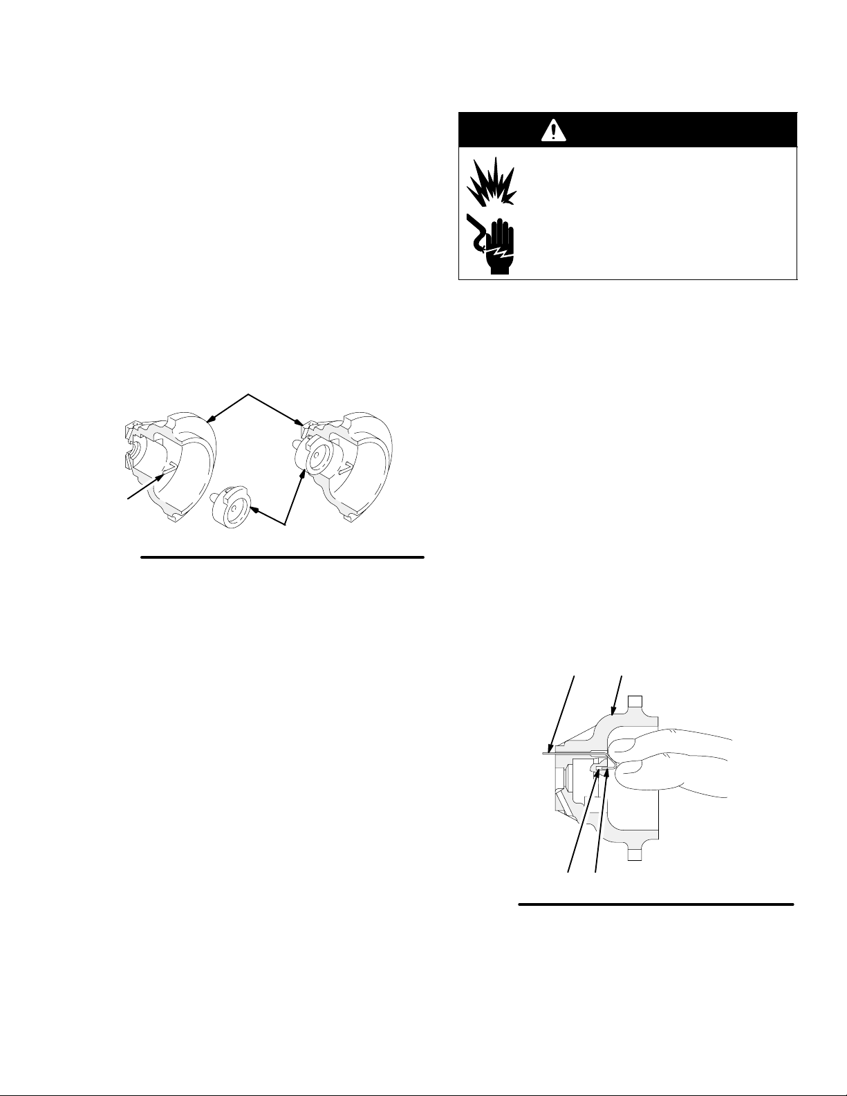
Test Barrel Resistance (See Fig. 27)
WARNING
Measure the resistance between the barrel contact
ring (26a) and the metal contact pin (E), using a metal
rod (D) and megohmmeter as shown in Fig. 27. Be
careful not to damage or scratch the inner surfaces of
the barrel with the metal rod.
The resistance should be 19 to 29 megohms. If the
resistance is incorrect, make sure the metal contact
pin (E) and the barrel contact ring (26a) are clean.
If the resistance is still outside the specified range:
1. Remove the barrel contact ring (26a) with a small
pick. There is a wire lead in the groove that the
contact ring was removed from.
2. With the metal rod (D) still inside the barrel as
shown in Fig. 27, measure the resistance between
the wire lead and the metal rod.
FIRE, EXPLOSION, AND
ELECTRIC SHOCK HAZARD
The barrel contact ring (26a) is a conductive contact ring, not a sealing
o-ring. To reduce the risk of sparking or
electric shock, do not remove the barrel
contact ring from the barrel except to
replace it and never operate the gun
without the contact ring in place. Do not
replace the contact ring with anything
but a genuine Graco part.
E
3. If the resistance is still outside the specified range,
the gun barrel needs to be replaced.
If the resistance is correct, install a new contact
ring (26a) and press it firmly into the groove on the
front of the barrel.
Be sure the contact ring is in place before operating the gun.
26a
Fig. 27
D
Wire lead in groove
behind contact ring
03247B
308387 29
Page 30

Tools Included with the Gun
Service
WARNING
Ball End Wrench
2 mm Socket Head Driver
9 mm Hex Nut Driver
Dielectric Grease
Prepare the Gun for Service
NOTE:
Check all the possible remedies in Troubleshoot-
ing, pages 25 to 27, before disassembling the gun.
If the plastic parts of the gun must be held in a vise,
use padded vise jaws to avoid damaging parts.
Only use genuine Graco parts. Do not mix or install
parts from other PRO gun models. Note that the air
cap, spray tip, and tip guard for this gun are
orange.
FIRE, EXPLOSION, AND
ELECTRIC SHOCK HAZARD
To reduce the risk of a fire, explosion, or
electric shock:
Be sure the turbine air (TA) is off
before flushing the gun or any part of
the system.
Clean all the parts with a compatible
solvent that is suitable for electrostatic equipment.
Do not service this equipment unless you are
trained and qualified.
Do not touch the gun nozzle or come within 4
inches (101.6 mm) of the nozzle during gun
operation.
CAUTION
Methylene chloride is not recommended as a flushing or cleaning solvent with this gun as it will damage
nylon components.
WARNING
EQUIPMENT MISUSE HAZARD
Do not mix or install parts from different
PRO gun models. Some PRO AA5500
Gun parts look similar to other PRO Gun
parts but they have different part numbers and they are not interchangeable.
Use of parts other than those specified
in the PRO AA5500 Gun parts list on
page 43 could alter the grounding conti-
nuity of the gun, cause parts to leak or
rupture, or cause the gun to malfunction, which
could result in a fire, explosion, electric shock, or
injection injury.
WARNING
INJECTION HAZARD
To reduce the risk of a serious injury,
including fluid injection, follow the Pres-
sure Relief Procedure on page 16
when you stop spraying, before servicing the gun,
and whenever you are instructed to relieve the
pressure.
1. Flush the gun with a compatible solvent.
2. Relieve the system pressure.
3. The service area must be clean. Remove the gun
from the worksite as instructed in the following
steps.
Continued on the next page.
30 308387
Page 31

Service
Prepare the Gun for Service (continued)
CAUTION
4. Remove the retaining nut and air cap assembly (1,
12, 13, 15) and the gun shroud (2). See Fig. 28.
You may have to turn the air cap with the tip guard
to remove the air cap from the gun.
5. Disconnect the fluid hose from the fluid inlet fitting
(3–marked P1 on the manifold). Use an open end
wrench to hold the fluid fitting hex and prevent it
from turning.
6. Loosen the bottom gun screw (21) until the gun (B)
sits loosely in the mounting bracket slot (A).
B
The piston return spring (105) is compressed
between the manifold (101) and gun body when they
are assembled. To avoid sudden movement of the
gun, loosen the bottom gun screw (21) before loosening the three manifold bolts (106). This allows the
gun to move forward gradually as the manifold bolts
are loosened. Hold the gun firmly in hand while
loosening the manifold bolts.
7. Holding the gun (B) firmly in hand, loosen the three
bolts (106) from the back of the manifold (101)
with the ball end wrench (77–not shown).
8. Remove the gun (B) from the manifold (101), and
take it to the service area.
106
105
101
1, 12, 13, 15
Fig. 28
2
102
A
3
21
03626
308387 31
Page 32

Tip Guard, Air Cap, Spray Tip, or Seat
Housing Replacement
Service
WARNING
1. Prepare the gun for service as instructed on
page 30.
2. Remove the seat housing (14) with the 9 mm
driver (84), supplied. See Fig. 30.
3. Replace the tip gasket (13a) if it is damaged.
CAUTION
The barrel resistor cartridge (B) is part of the barrel
and is not replaceable. Refer to page 32. To avoid
destroying the gun barrel, do not attempt to remove
the barrel resistor cartridge.
WARNING
FIRE, EXPLOSION, AND
ELECTRIC SHOCK HAZARD
The barrel contact ring (26a) is a conductive contact ring, not a sealing o-ring.
Refer to Fig. 29. To reduce the risk of
sparking or electric shock, do not
remove the barrel contact ring from the
barrel except to replace it and never
operate the gun without the contact ring
in place. Do not replace the contact ring
with anything but a genuine Graco part.
FIRE, EXPLOSION, AND
ELECTRIC SHOCK HAZARD
To reduce the risk of fire, explosion, and
electric shock, never operate the spray
gun with a bent, damaged or missing
electrode (15a).
2
13a
13
15
12
1
26a
Fig. 29
Tighten the seat housing (14) with the 9 mm driver (84) until it is
snug, then tighten it 1/4 turn more; do not over-tighten it.
03627
4. Install the seat housing (14) with the 9 mm driver
(84). Tighten the seat housing until it’s snug and
then tighten it 1/4 turn more; do not over-tighten.
CAUTION
To avoid damaging the seat housing and gun barrel,
never over-tighten the seat housing. Over-tightening
may affect the fluid shut-off.
5. Make sure the electrode (15a) is not bent, damaged or missing from the air cap. See Fig. 31. See
page 33 to install the electrode.
32 308387
Fig. 30
14
84
B
03237
Page 33
Service
Tip Guard, Air Cap, Spray Tip, or Seat
Housing Replacement (continued)
6. Place the spray tip (13) in the air cap (15). Align
the tab of the tip with the groove in the air cap.
See Fig. 31. Do not bend the electrode wire (15a).
7. Slide the shroud (2) onto the gun. See Fig. 29.
8. Install the spray tip (13) and air cap (15), tip guard
(12), and retaining nut (1). Tighten the retaining nut
firmly.
9. Test the gun resistance as instructed on page 28.
10. Install the gun onto the manifold and bracket as
instructed on page 41.
15
15a
13
Fig. 31
01995
Electrode Replacement
WARNING
FIRE, EXPLOSION, AND
ELECTRIC SHOCK HAZARD
To reduce the risk of fire, explosion, and
electric shock, never operate the spray
gun with a bent, damaged or missing
electrode (15a).
1. Prepare the gun for service as instructed on
page 30.
2. Remove the retaining nut (1), tip guard, (12), air
cap (15), spray tip (13), and gun shroud (2) as
instructed on page 32.
3. Pull the electrode (15a) out of the backside of the
air cap with a needle nose pliers. Refer to Fig. 31.
4. Push the new electrode (15a) through the air cap
hole. Place firm finger pressure on the electrode
wire on the backside of the air cap, and make sure
the short end (BB) of the electrode engages into
the hole (CC) as shown in Fig. 32.
5. Slide the shroud (2) onto the gun.
6. Install the spray tip (13), air cap (15), tip guard
(12), and retaining nut (1) as instructed at left.
Tighten the retaining nut firmly.
7. Test the gun resistance as instructed on page 28.
8. Install the gun onto the manifold and bracket as
instructed on page 41.
15a 15
BBCC
Fig. 32
02013
308387 33
Page 34

Service
Fluid Tube Removal and Replacement
To remove the fluid tube assembly (18) for cleaning or
replacement:
1. Prepare the gun for service as instructed on
page 30.
2. Disconnect the bottom fluid tube nut (C). See
Fig. 33.
3. Carefully unscrew the top fluid tube nut (D).
CAUTION
Be careful not to damage the fluid tube assembly
(18) when cleaning or installing it, especially the
sealing surface (E). See Fig. 34. If the sealing surface is damaged, the entire fluid tube assembly must
be replaced.
Fluid Filter Replacement
1. Prepare the gun for service as instructed on
page 30.
2. Disconnect the bottom fluid tube nut (C). See
Fig. 33.
3. Remove the fluid filter (4). Clean or replace the
filter, as needed.
4. Install the fluid filter (4) and tighten the bottom fluid
tube nut (C) onto the fluid fitting (3); make sure the
top fluid tube nut (D) remains tightened.
5. Install the shroud (2), spray tip (13), air cap (15),
tip guard (12), and retaining nut (1) as instructed
on page 33. Tighten the retaining nut firmly.
6. Test the gun resistance as instructed on page 28.
7. Install the gun onto the manifold and bracket as
instructed on page 41.
Tighten the nut (D) about 1/4 to 1/2 turn past hand-tight; there
will be a gap between the nut and barrel; do not over-tighten it.
4. Apply dielectric grease to the entire length of the
plastic extension on the end of the fluid tube (18).
See Fig. 34.
5. Apply a low strength thread sealer (such as purple
Loctite) to the fluid tube nut (D) threads.
6. Install the fluid tube into the gun barrel by tightening the top fluid tube nut (D) hand-tight, then turn it
1/4 to 1/2 turn with a wrench. See Fig. 33. There
will be a gap between the nut and barrel. Do not
over-tighten it.
7. Make sure the fluid filter (4) is in place, then
tighten the bottom fluid tube nut (C) onto the fluid
fitting (3); make sure the top fluid tube nut (D)
remains tightened.
8. Install the shroud (2), spray tip (13), air cap (15),
tip guard (12), and retaining nut (1) as instructed
on page 33. Tighten the retaining nut firmly.
3
D
Fig. 33
Apply low strength (purple) Loctite or equivalent to the threads
Apply dielectric grease to the entire length of the fluid tube
plastic extension
C
4
18
03685
9. Test the gun resistance as instructed on page 28.
10. Install the gun onto the manifold and bracket as
instructed on page 41.
34 308387
Fig. 34
E
CD
2079
Page 35

Service
Piston Repair
1. Prepare the gun for service as instructed on
page 30.
2. Remove the jam nut (8), actuator arm (19), and
adjustment nut (17). See Fig. 35.
3. Push on the piston rod (23g) to push the piston
assembly out the back of the gun.
4. Inspect the o-rings (23a, 23b, 23c) and u-cup
packing (23f) for damage. See Fig. 37. Refer to
Fig. 38 to isolate any air leakage problems.
5. Lubricate the o-rings (23a, 23b, 23c) and u-cup
packing (23f) with petroleum jelly.
6. Align the two stems (23d) with the holes in the gun
body and press the piston assembly into the back
of the gun until it bottoms.
7. Installing the Actuator Arm and Nuts:
a. Install the adjustment nut (17), actuator arm
(19), and jam nut (8) onto the piston rod (23g).
See Fig. 35.
NOTE: The jam nut (8) has a slightly larger hex and a
thinner profile than the adjustment nut (17).
a. Thread the jam nut (8) flush with the end of the
piston rod (23g).Tighten the adjustment nut
(17) against the actuator arm (19). When
properly assembled, there should be about a
0.125 in. (3 mm) gap between the actuator
arm (19) and the fluid packing rod nut (U),
which allows the atomizing air to actuate
before the fluid actuates. See Fig. 36.
8. Install the shroud (2), spray tip (13), air cap (15),
tip guard (12), and retaining nut (1) as instructed
on page 33. Tighten the retaining nut firmly.
9. Test the gun resistance as instructed on page 28.
10. Install the gun onto the manifold and bracket as
instructed on page 41.
There should be a 0.125 in. (3 mm) gap between the actuator
arm (19) and the fluid packing rod nut (U).
19 U
Fig. 36
Apply a very light coat of lubricant to the o-rings (23a, 23b, 23c)
and u-cup (23f)
Align the two stems (23d) with the holes in the gun body and
press the piston assembly until it bottoms.
23d
23c
23b
23e
23f
23g
23a
Fig. 37
Description Function
O-Ring (23a)
Shaft Air Seal
O-Ring (23b)
Front Air Seal
O-Ring (23c)
Back Air Seal
U-cup (23f)
Cylinder Air
Seal
It seals the cylinder air along the piston
rod. If the air leaks along the piston rod
(23g), replace this o-ring (23a).
It is the air shut-off seal. If the air leaks
from the air cap when the gun is detriggered, replace these o-rings.
It separates the cylinder air pressure from
the atomizing air pressure.
If the air leaks from the small vent hole in
the back of the manifold when the gun is
triggered, replace the u-cup.
23c
23b
04823
03530
Fig. 35
8191723g
03628
Fig. 38
23a
23f
03531
308387 35
Page 36

Service
Barrel Removal
1. Prepare the gun for service as instructed on
page 30.
2. Disconnect the bottom fluid tube nut (C). See
Fig. 39.
3. Remove the jam nut (8) and actuator arm (19).
4. Loosen the three screws (24) with the ball end
wrench (77). See Fig. 40.
26
5. Hold the gun body (29) with one hand and pull the
barrel (26) straight away from the body to remove
it. See Fig. 41.
CAUTION
To avoid damaging the power supply (27), pull the
gun barrel straight away from the gun body. If necessary, gently move the barrel from side to side to free
the power supply from the gun body.
29
Fig. 39
77
24
819
27
C
26
29
03628
Fig. 40
36 308387
03238
Fig. 41
03239
Page 37

Service
Fluid Packing Adjustment
If fluid leaks from the fluid needle area, the fluid packings may be loose. Tighten the packings, following the
procedure below.
1. Prepare the gun for service as instructed on
page 30.
2. Remove the seat housing (14) with the 9 mm
driver (84), supplied. See Fig. 30, page 32. The
seat housing (14) must be removed before adjusting the fluid packings.
3. Remove the barrel as instructed on page 36.
4. Place the 2 mm driver (79) into the back of the
fluid needle assembly. See Fig. 42. Push the tool
in and turn it clockwise, slightly, to tighten the
packings.
5. Install the seat housing as instructed on page 32.
6. Assemble the gun as instructed on page 40.
79
4. Place the 2 mm driver (79) in the back of the fluid
needle assembly (28). See Fig. 42. Push the tool
in and turn it counterclockwise about 12 full turns
to unthread the needle.
5. Insert the 2 mm driver (79) into the front of the gun
and push the fluid needle assembly (28) out the
back of the gun body.
CAUTION
To avoid damaging the fluid needle assembly (28),
completely unthread the needle before pushing it out
of the barrel.
6. Apply petroleum jelly or dielectric grease to the
new fluid needle assembly (28) and install it into
the gun barrel. See Fig. 43.
7. Push in on the needle with the 2 mm driver (79)
and tighten the assembly clockwise to 4.5–5.0
in-lbs (0.5–0.6 Nm) [about 1/4 to 1/2 turn past
snug]. See Fig. 42.
8. Install the seat housing as instructed on page 32.
To tighten
packings
T o remove
needle
Fig. 42
Fluid Needle Assembly Removal
1. Prepare the gun for service as instructed on
page 30.
2. Remove the seat housing (14) with the 9 mm
driver (84), supplied. See Fig. 30, page 32.
3. Remove the barrel as instructed on page 36.
03241
9. Assemble the gun as instructed on page 40.
Apply petroleum jelly or dielectric grease to the fluid needle (28).
Tighten the fluid needle with the driver (79-see Fig. 42) to
4.5–5.0 in-lbs (0.5–0.6 Nm) [about 1/4–1/2 turn past snug].
28
Fig. 43
03242
308387 37
Page 38

Service
Power Supply Removal and Replacement
NOTES:
To avoid a loss in electrostatic performance, inspect
the gun body power supply cavity for dirt or moisture. Clean the cavity with a clean, dry rag.
Do not expose the seal (D) or o-ring (27a) to sol-
vents as this will damage them.
1. Prepare the gun for service as instructed on
page 30.
2. Remove the barrel as instructed on page 36.
3. Grasp the power supply (27) with your hand. With
a gentle side-to-side motion, being careful not to
damage the power supply, pull the power supply
free from the gun body (29), then pull it straight
out. See Fig. 44.
4. Inspect the power supply for any physical damage.
Test the power supply electrical resistance as
instructed on page 28. If necessary, replace the
power supply.
5. Before installing the power supply, inspect the seal
(D) for any damage or swelling. Make sure the
gaskets and pads (27a–27f) are in place.
6. Lubricate the o-ring (25a) and install the power
supply in the gun body.
7. Assemble the gun as instructed on page 40.
Lower Voltage Setting Adjustment
The kV switch, in the manifold, enables you to switch
between full voltage and a lower voltage output. The
lower voltage is factory set at 60 kV, but can be
adjusted between 45 and 80 kV.
To adjust the low voltage setting, use a small blade
end screw driver to turn the potentiometer (W). Turn it
clockwise to decrease the voltage or counterclockwise
to increase the voltage; fully clockwise is 45 kV, fully
counterclockwise is 80 kV.
Apply a very light coat of lubricant to the o-ring (25a).
Do not expose the seal (D) or gasket (27a) to solvents.
26
Fig. 44
27a
27
D
27b
W
27f
27c
30
29
V
25a
25b
25
03243B
38 308387
Page 39

Service
Turbine Alternator Removal and
Replacement
NOTE: Replace the turbine bearings after 2000 hours
of operation. See your authorized Graco representative.
1. Prepare the gun for service as instructed on
page 30.
2. Remove the power supply from the gun body as
described on page 38.
3. Squeeze the two ends of the retaining ring (30)
together and carefully pull the alternator (25) away
from the power supply (27) until the wire connector
(V) disengages. See Fig. 44.
4. Use an ohmmeter to test the turbine alternator coil.
Measure the resistance between the two outer
terminals of the 3-wire connector (V). Resistance
should be 3 to 5 ohms. If the reading varies from
this value, replace the alternator.
5. Connect the 3-wire connector to the 3 prongs in
the power supply. Push the alternator (25) onto the
power supply (27) until the retaining ring (30)
engages with the alternator.
6. Assemble the gun as instructed on page 40.
308387 39
Page 40

Service
Barrel Installation
1. Be sure the gaskets (11, 27a) and spring (20) are
in place. See Fig. 45. Replace the parts if they are
damaged.
2. Place the barrel (26) over the power supply (27)
and onto the gun body (29). Make sure the fluid
needle spring (20) is seated properly.
3. Pressing the barrel and handle together, tighten
the three screws (24) oppositely and evenly to 18
in-lbs (2 Nm) maximum (about a half turn past
snug), using the ball end wrench (77); do not
over-tighten.
CAUTION
To avoid damaging the gun, do not over-tighten the
screws (24).
Tighten the screws (24) to 18 in-lbs (2 Nm) maximum (about
half turn past snug), using the wrench (77) provided.
4. Make sure the fluid filter (4) is in place, then
tighten the bottom fluid tube nut (C) onto the fluid
fitting (3); make sure the top fluid tube nut (D)
remains tightened.
5. Install and adjust the actuator arm (19) and jam
nut (8) onto the piston rod (23g) as instructed on
page 35.
6. Install the shroud (2), spray tip (13), air cap (15),
tip guard (12), and retaining nut (1) as instructed
on page 32. Tighten the retaining nut firmly.
7. Test the gun resistance as instructed on page 28.
8. Install the gun onto the manifold and bracket as
instructed on page 41.
29
Fig. 45
26
24
11
27a
27
3
17
23g
4
20
C
D
19
8
03240
40 308387
Page 41

Service
Install the Gun onto the Manifold and
Mounting Bracket
1. Remove the retaining nut (1), tip guard, (12), air
cap (15), spray tip (13), and gun shroud (2). See
Fig. 46.
2. Make sure the gaskets (108, 121) and spring (105)
are in place on the manifold (101). Inspect the
parts for damage and replace them as needed.
3. Secure the gun (B) to the manifold (101) by tightening the three screws (106) with the ball end
wrench (77–not shown).
B
4. Connect the fluid hose to the fluid inlet fitting
(3–marked P1 on the manifold). Use an open end
wrench to hold the fluid fitting hex and prevent it
from turning.
5. Secure the gun (B) to the mounting bracket (102)
by tightening the screw (21) with the ball end
wrench (77).
6. Slide the shroud (2) over the gun.
7. Install the spray tip (13), air cap (15), tip guard
(12), and retaining nut (1) as instructed on page
32. Tighten the retaining nut firmly.
121
108
105
106
101
1, 12, 13, 15
Fig. 46
2
102
3
21
03626
308387 41
Page 42

Spray Gun Parts
Item 23 includes 23a–23g
Item 25 includes 25a & 25b
Item 27 includes 27a–27f
2
9
1
12
11
15
13
13a
14
15a
24
26
26a
REF 18
27f
27b
25a
25
25b
30
27c
19
28
27
75
See page 45
27a
23e
23f
23d
23c
23b
20
7
6
17
8
10
21
23a
29
23g
to order parts
18
42 308387
3
4
03244B
Page 43

Spray Gun Parts
WARNING
EQUIPMENT MISUSE HAZARD
Use only genuine Graco replacement
parts. Some PRO AA5500 gun parts
look similar to other PRO gun parts but
they have different part numbers and
they are not interchangeable. Use of
parts other than those specified in the
parts list below could alter the grounding
continuity of the gun, cause parts to leak
or rupture, or cause the gun to malfunction, which could result in a fire, explosion, electric
shock, or injection injury.
Part No. 236688 Spray Gun Assembly
Includes items 1–84
Ref.
No. Part No. Description Qty .
1 189768 RETAINING NUT, air cap 1
2 189770 SHROUD 1
3 189366 FLUID FITTING 1
4 205264 FLUID FILTER 1
6 189367 CAP, exhaust 1
7 185122 MUFFLER/FLAME ARRESTOR 1
8 101324 NUT, hex jam; 1/4”–20 1
9 110492 O-RING; PTFE
10 108290 SCREW 1
11 185113 GASKET, gun body; polyethylene 1
12 188479 TIP GUARD 1
13 GG3XXX SPRAY TIP, customer choice; Includes
item 13a; See pg. 49 to order 1
13a 183459
14 235797 SEAT HOUSING 1
15 235947 AIR CAP & ELECTRODE ASSY.;
15a 188676
17 102025 NUT, hex; 1/4”-20 1
18 235843 FLUID TUBE ASSY. 1
19 186766 ARM, actuator 1
21 112689 SCREW, socket; 1/4 x 0.75” 1
SEAL, spray tip 1
Includes item 15a 1
ELECTRODE; Order Electrode Kit,
part no. 236001, to receive
5 electrodes 1
1
Ref.
No. Part No. Description Qty.
23 236826 PISTON ASSY;
Includes items 23a–23g 1
23a 111508
23b 111504
23c 112319
23d 189355
23e 189747
23f 189752
23g 189754
24 185096 SCREW, cap, relieved; M5 x 0.8 3
25 222319 ALTERNATOR, turbine
25a 110073
25b 185124
26 235827 BARREL, gun; Includes item 26a 1
26a 111261
27 224093 POWER SUPPLY ASSY; 85 kV
27a 186840 GASKET, power supply 1
27b 185099
27c 185145
27e 185141
27f 192361
28 241662 FLUID NEEDLE ASSY
28a 112876 SPRING 1
29 190055 BODY, gun 1
30 185114 RET AINER RING, alternator 1
37 112638 FITTING, fiber optic (shown on
75 236832 MANIFOLD ASSY.
77 107460 WRENCH, ball end 1
78 180060 SIGN, warning, English 1
79 112080 DRIVER, socket head, 2 mm 1
80 222385 WARNING CARD 1
81 179791 TAG, warning 1
82 189888 COVER, gun 1
83 217115 GREASE, dielectric 1
84 110087 DRIVER, hex nut, 9 mm 1
These parts are included in Air Seal Repair Kit 236827,
which may be purchased separately.
These parts are not shown in the parts drawing.
Replacement Danger and Warning labels, tags and cards
are available at no cost. French, German, and Spanish
warning signs are also available.
O-RING; fluoroelastomer 1
O-RING; fluoroelastomer 2
O-RING; fluoroelastomer 2
STEM, piston 2
PISTON 1
PACKING, u-cup; UHMW
polyethylene 1
ROD, piston 1
Includes items 25a & 25b 1
O-RING; Viton 1
CUSHION 1
CONTACT RING, barrel 1
Includes items 27a–27f 1
PAD 1
PAD 2
CUSHION 1
PAD 1
Includes item 28a 1
page 44) 1
See separate parts list on page 45 1
308387 43
Page 44
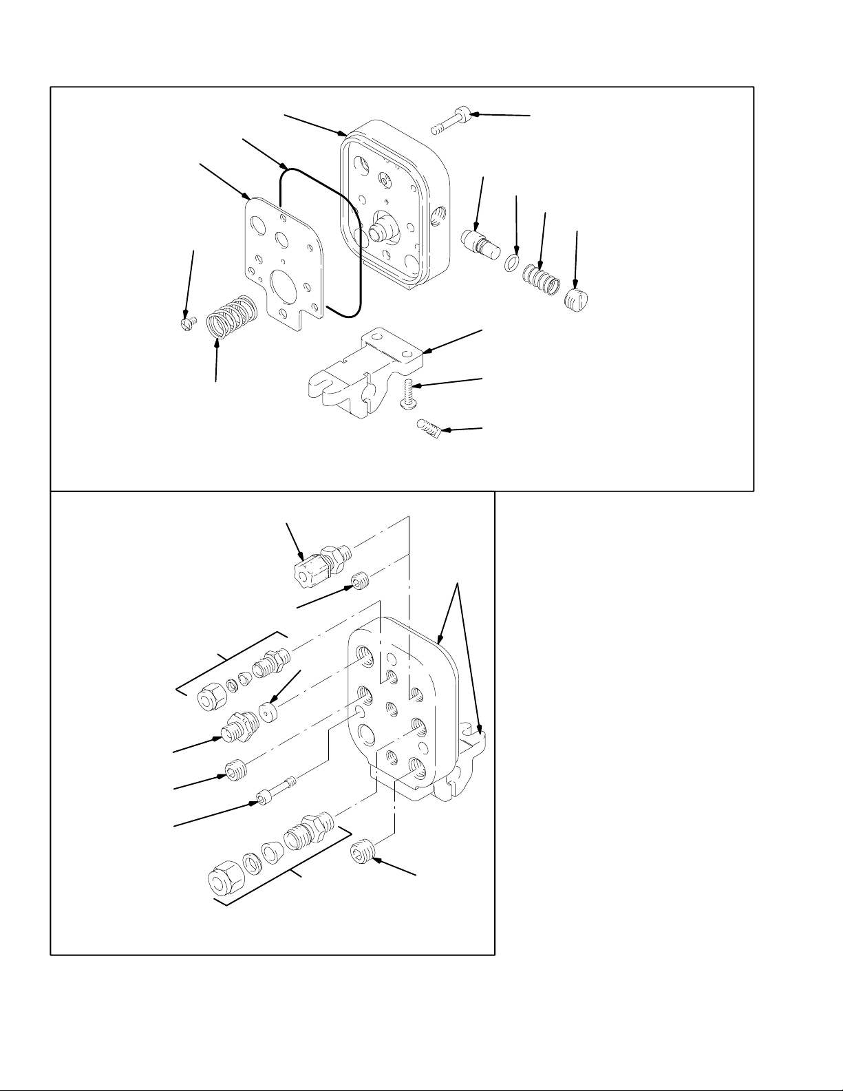
Manifold Parts
108
109
105
121
101
Front View
110
102
104
103
123
106
122
111
03462
113
119
106
107
37
115
114
112
Ref. 101
& 102
116
Apply low strength (purple) Loctite or an
equivalent sealant to the threads.
Press fit the spring (105)
Tighten the fitting until the hex bottoms against
the manifold.
This fitting (113) has left-hand threads.
Install the kV cap (111) flush to the outside
surface.
Concave side of the disk (114) faces toward the
manifold.
Replace the spring (122) every 300,000 cycles.
An optional fiber optic fitting (37) is included
with the gun assembly; see page 43. Remove
the plug (115) and install the fitting (37) if a kV
display is being used.
44 308387
Back View
03629
Page 45

Manifold Parts
WARNING
EQUIPMENT MISUSE HAZARD
Use only genuine Graco replacement
parts. Some PRO AA5500 gun parts
look similar to other PRO gun parts but
they have different part numbers and
they are not interchangeable. Use of
parts other than those specified in the
parts list below could alter the grounding
continuity of the gun, cause parts to leak
or rupture, or cause the gun to malfunction, which could result in a fire, explosion, electric
shock, or injection injury.
Part No. 236832 Manifold Assembly
Includes items 101–123
Ref.
No. Part No. Description Qty.
101 190057 MANIFOLD 1
102 189581 MOUNTING BRACKET 1
103 110465 BOLT, square head 2
104 112689 SCREW; 1/4–20 x 0.75” 2
105 112640 SPRING, compression 1
106 186846 BOLT, manifold; M5 x 0.8 3
107 111157 FITTING, tube; for 1/4” OD tube 3
108 189363 GASKET , manifold 1
109 108290 SCREW; 8–32 x 1/4” 2
1 10 236696 kV SWITCH 1
1 11 189365 kV CAP 1
112 110078 FITTING, tube; for 3/8” OD tube 1
113 186845 FITTING, turbine; 1/4–18 npsm
left hand thread 1
1 14 107107 REGULATOR, disk 1
1 15 112645 PLUG; 1/8–27 npt 1
1 16 112646 PLUG; 5/8–18 x 5/8” 1
119 112678 PLUG; 1/4 npt 1
121 190301 GASKET, foam 1
122 112641 SPRING 1
123 111316 O-RING, fluoroelastomer 1
Part No. 236852 Optional Fiber Optic Kit
The kit is not included with the gun. The kit is only for
use with the ES Display Part No. 224117 to improve
light transmission when two bulkhead splices are used.
The kit includes items 201–203.
Ref.
No. Part No. Description Qty.
201 112638 FITTING, fiber optic; see item 37 on
page 44 1
202 111224 LENS 1
203 189875 SLEEVE 1
202
203
04798
* These parts are included in Fluid Seal Repair Kit 236828,
which may be purchased separately.
These parts are included in Air Seal Repair Kit 236827,
which may be purchased separately.
Optional gaskets are available:
Part No. 11 1180: Viton
308387 45
Page 46

Accessories
Use Only Genuine Graco Parts and Accessories
AIR LINE ACCESSORIES
Conductive Air Supply Hose; black
100 psi (7 bar, 0.7 MPa) Maximum Working Pressure
FM Approved; Color coded black; 0.315 in. (8 mm) ID;
1/4 npsm(f) x 1/4 npsm(f) left-hand thread
220444 6 ft (1.8 m)
218100 15 ft (5 m)
218101 25 ft (8 m)
218102 36 ft (11 m)
218103 50 ft (15 m)
220119 75 ft (23 m)
220120 100 ft (30.5 m)
Conductive Air Supply Hose; gray
100 psi (7 bar, 0.7 MPa) Maximum Working Pressure
FM Approved; Color coded gray; More flexible than
black hose; 0.315 in. (8 mm) ID; 1/4 npsm(f) x 1/4
npsm(f) left-hand thread
223068 6 ft (1.8 m)
223069 15 ft (5 m)
223070 25 ft (8 m)
223071 36 ft (11 m)
223072 50 ft (15 m)
223073 75 ft (23 m)
223074 100 ft (30.5 m)
Bleed-type Master Air Valve 107141
300 psi (21 bar, 2.1 MPa) Maximum Working Pressure
Relieves air trapped in the air line
between the paint pump air motor
and this valve when closed. 3/4 npt
FLUID LINE ACCESSORIES
Nylon Static Free Fluid Hoses
3300 psi (228 bar, 22.8 MPa) Maximum Working
Pressure
Part No. ID Length Thread Size
214700 3/16 in (4.8 mm) 2 ft (610 mm) 1/4 npsm(f)
214701 3/16 in (4.8 mm) 3 ft (914 mm) 1/4 npt(mxf)
214699 3/16 in (4.8 mm) 6 ft (1.8 m) 1/4 npsm(f)
214698 3/16 in (4.8 mm) 25 ft (7.6 m) 1/4 npsm(f)
214697 3/16 in (4.8 mm) 50 ft (15.2 m) 1/4 npsm(f)
Nylon Static Free Fluid Hoses
3000 psi (207 bar, 20.7 MPa) Maximum Working
Pressure
Conductive Air Supply Hose; red
100 psi (7 bar, 0.7 MPa) Maximum Working Pressure
Meets CENELEC EN 50 050 requirement for metallic
ground path; Color coded red; Stainless steel braid
ground path; 0.315 in. (8 mm) ID; 1/4 npsm(f) x 1/4
npsm(f) left-hand thread
235068 6 ft (1.8 m)
235069 15 ft (5 m)
235070 25 ft (8 m)
235071 36 ft (11 m)
235072 50 ft (15 m)
235073 75 ft (23 m)
235074 100 ft (30.5 m)
Air Shutoff Valve 224754
150 psi (10 bar, 1.0 MPa) Maximum Working Pressure
For turning air to gun off or on. 1/4 npsm(m) x
1/4 npsm(f) left-hand thread
Part No. ID Length Thread Size
223763 1/4 in (6.4 mm) 14 in (356 mm) 1/4 npt(m)
223760 1/4 in (6.4 mm) 28 in (711 mm) 1/4 npsm(f)
223761 1/4 in (6.4 mm) 3 ft (914 mm) 1/4 npsm(f) x
1/4 npt(m)
223756 1/4 in (6.4 mm) 15 ft (4.6 mm) 1/4 npsm(f)
223540 1/4 in (6.4 mm) 25 ft (7.6 m) 1/4 npsm(f)
223541 1/4 in (6.4 mm) 50 ft (15.2 m) 1/4 npsm(f)
High Pressure Ball Valves
5000 psi (350 bar, 35 MPa) Maximum Working
Pressure
For turning fluid off or on to the gun and for relieving
fluid line pressure at the pump
210657 1/2 npt(m), Viton seals
210658 3/8 npt(m), Viton seals
210659 3/8 x 1/4 npt(m), Viton seals
214037 1/4 npt(m), PTFEseals
46 308387
Page 47

Accessories
Use Only Genuine Graco Parts and Accessories
GUN CONTROL AND MONITORING
ACCESSORIES
For more information about gun controls and monitoring
accessories contact your Graco representative.
KV Display Module 189762
Receives fiber optic transmission from the gun and
displays the gun’s output voltage. Battery operated.
ES Display Module 224117
Receives fiber optic transmission from the gun and
displays the gun’s output voltage and current. Mounts
in a standard 19” DIN Rack. Refer to manual 308265.
0309
CABLE ACCESSORIES
Fiber Optic Cable Assembly
For connection between gun manifold and display
module or between bulkhead connector and display
module.
PART NO. LENGTH
224682 25 ft (8 m)
224684 50 ft (15 m)
224686 100 ft (30.5 m)
0330
Fiber Optic Cable Extender
For connection between gun manifold and bulkhead
connector.
PART NO. LENGTH
224672 25 ft (8 m)
224674 50 ft (15 m)
224676 100 ft (30.5 m)
24 Volt Power Supply 235301
Provides 24 volt power for up to 23 ES Display Modules.
01339
0184
308387 47
Page 48

Accessories
Use Only Genuine Graco Parts and Accessories
MISCELLANEOUS ACCESSORIES
Electrode Replacement Kit 236001
Includes five electrodes
Grounding Clamp and Wire 222011
12 ga, 25 ft (7.6 m) wire
Megohmmeter 241079
500 Volt output; 0.01–2000 megohms;
Not for use in Hazardous areas
TI0377
0189
Gun High Voltage Probe and Meter 236003
For direct measurement of gun output voltage
Paint Resistance Meter 722886
Used with 722860 Paint Probe to measure resistance
of paint; Not for use in Hazardous areas
Paint Probe 722860
Used with 722886 Paint Resistance Meter to
measure resistance of paint; Not for use in
Hazardous areas
Safety Warning Signs
Available at no charge from Graco
180060 Warning Sign (English)
48 308387
Page 49

Spray Tip Selection Chart
Part No.
GG3107 2–4 (50–100)
GG3207 4–6 (100–150)
GG3307 6–8 (150–200)
GG3209 4–6 (100–150)
GG3309 6–8 (150–200)
GG3409 8–10 (200–250)
GG3211 4–6 (100–150)
GG3311 6–8 (150–200)
GG3411 8–10 (200–250)
GG3511 10–12 (250–300)
GG3611 12–14 (300–350)
GG3213 4–6 (100–150)
GG3313 6–8 (150–200)
GG3413 8–10 (200–250)
GG3513 10–12 (250–300)
GG3613 12–14 (300–350)
GG3215 4–6 (100–150)
GG3315 6–8 (150–200)
GG3415 8–10 (200–250)
GG3515 10–12 (250–300)
GG3615 12–14 (300–350)
GG3217 4–6 (100–150)
GG3317 6–8 (150–200)
GG3417 8–10 (200–250)
GG3517 10–12 (250–300)
GG3617 12–14 (300–350)
Fan Width at
10 in. (260 mm)
in. (mm)
Orifice Size
in. (mm)
0.007 (0.178)
0.009 (0.229)
0.01 1 (0.279)
0.013 (0.330)
0.015 (0.381)
0.017 (0.432)
Part No.
GG3319 6–8 (150–200)
GG3419 8–10 (200–250)
GG3519 10–12 (250–300)
GG3619 12–14 (300–350)
GG3719 14–16 (350–400)
GG3421 8–10 (200–250)
GG3521 10–12 (250–300)
GG3621 12–14 (300–350)
GG3721 14–16 (350–400)
GG3423 8–10 (200–250)
GG3523 10–12 (250–300)
GG3623 12–14 (300–350)
GG3425 8–10 (200–250)
GG3625 12–14 (300–350)
Fan Width at
10 in. (260 mm)
in. (mm)
Orifice Size
in. (mm)
0.019 (0.483)
0.021 (0.533)
0.023 (0.584)
0.025 (0.635)
308387 49
Page 50

Technical Data
Category Data
Weight (gun and
manifold)
Maximum Air
Working Pressure
Maximum Fluid
Working Pressure
Maximum Noise
Level with fan and
alomization air at
100 psi (7 bar,
0.7 MPa)**
Voltage Output 0–85 kV
Short Circuit Current
Output
Paint Resistivity
Range
3.57 lb (1620 g)
100 psi (7 bar, 0.7 MPa)
3000 psi (207 bar,
20.7 MPa)
Sound Pressure 97.0 Db(A)
Sound Power 107.0 Db(A)
120 mA
3 megohm-cm to infinity
Category Data
Maximum Fluid
Temperature
Turbine Air Inlet 1/4 npsm(m), left-hand
Fluid Inlet 1/4 npsm(m)
Wetted Parts Stainless Steel, Nylon, PEEK,
Sound pressure was measured per Cagi Pneurop, 1969.
The measurement was taken 3.28 feet (1 meter) from the
air cap.
Sound power was measured per ISO–3744, 1981.
Viton is a registered trademark of the DuPont
Company.
Loctite
is a registered trademark of the Loctite Corporation.
120F (49C)
Ultra High Molecular Weight
Polyethylene, Tungsten
Carbide
Manual Change Summary
This manual has been changed per ECO’s V6534 and V6565.
50 308387
Page 51

Notes
308387 51
Page 52

Graco Standard Warranty
Graco warrants all equipment manufactured by Graco and bearing its name to be free from defects in material and workmanship on the
date of sale by an authorized Graco distributor to the original purchaser for use. With the exception of any special, extended, or limited
warranty published by Graco, Graco will, for a period of twelve months from the date of sale, repair or replace any part of the equipment
determined by Graco to be defective. This warranty applies only when the equipment is installed, operated and maintained in accordance with Graco’s written recommendations.
This warranty does not cover, and Graco shall not be liable for general wear and tear, or any malfunction, damage or wear caused by
faulty installation, misapplication, abrasion, corrosion, inadequate or improper maintenance, negligence, accident, tampering, or substitution of non-Graco component parts. Nor shall Graco be liable for malfunction, damage or wear caused by the incompatibility of
Graco equipment with structures, accessories, equipment or materials not supplied by Graco, or the improper design, manufacture,
installation, operation or maintenance of structures, accessories, equipment or materials not supplied by Graco.
This warranty is conditioned upon the prepaid return of the equipment claimed to be defective to an authorized Graco distributor for
verification of the claimed defect. If the claimed defect is verified, Graco will repair or replace free of charge any defective parts. The
equipment will be returned to the original purchaser transportation prepaid. If inspection of the equipment does not disclose any defect
in material or workmanship, repairs will be made at a reasonable charge, which charges may include the costs of parts, labor, and
transportation.
THIS WARRANTY IS EXCLUSIVE, AND IS IN LIEU OF ANY OTHER WARRANTIES, EXPRESS OR IMPLIED, INCLUDING BUT
NOT LIMITED TO WARRANTY OF MERCHANTABILITY OR WARRANTY OF FITNESS FOR A PARTICULAR PURPOSE.
Graco’s sole obligation and buyer’s sole remedy for any breach of warranty shall be as set forth above. The buyer agrees that no other
remedy (including, but not limited to, incidental or consequential damages for lost profits, lost sales, injury to person or property , o r a ny
other incidental or consequential loss) shall be available. Any action for breach of warranty must be brought within two (2) years of the
date of sale.
Graco makes no warranty , and disclaims all implied warranties of merchantability and fitness for a particular purpose in connection
with accessories, equipment, materials or components sold but not manufactured by Graco. These items sold, but not manufactured
by Graco (such as electric motors, switches, hose, etc.), are subject to the warranty, if any, of their manufacturer. Graco will provide
purchaser with reasonable assistance in making any claim for breach of these warranties.
In no event will Graco be liable for indirect, incidental, special or consequential damages resulting from Graco supplying equipment
hereunder, or the furnishing, performance, or use of any products or other goods sold hereto, whether due to a breach of contract,
breach of warranty, the negligence of Graco, or otherwise.
FOR GRACO CANADA CUSTOMERS
The parties acknowledge that they have required that the present document, as well as all documents, notices and legal proceedings
entered into, given or instituted pursuant hereto or relating directly or indirectly hereto, be drawn up in English. Les parties reconnaissent avoir convenu que la rédaction du présente document sera en Anglais, ainsi que tous documents, avis et procédures judiciaires
exécutés, donnés ou intentés à la suite de ou en rapport, directement ou indirectement, avec les procedures concernées.
Graco Phone Number
TO PLACE AN ORDER, contact your Graco distributor, or call this number to identify the distributor closest to you:
1–800–367–4023 Toll Free
All written and visual data contained in this document reflects the latest product information available at the time of publication.
Graco reserves the right to make changes at any time without notice.
52 308387
International Offices: Belgium, Korea, Hong Kong, Japan
Sales Offices: Minneapolis, Detroit
www.graco.com
GRACO INC. P.O. BOX 1441 MINNEAPOLIS, MN 55440–1441
PRINTED IN U.S.A. 308387 June 1994, Revised September 2000
 Loading...