

Page 1
INSTRUCTIONS–P
This
manual contains IMPORT
ARNINGS AND INSTRUCTIONS
W
READ AND RET
AIN FOR REFERENCE
ARTS LIST
ANT
307–706
Rev. R
Supersedes
P
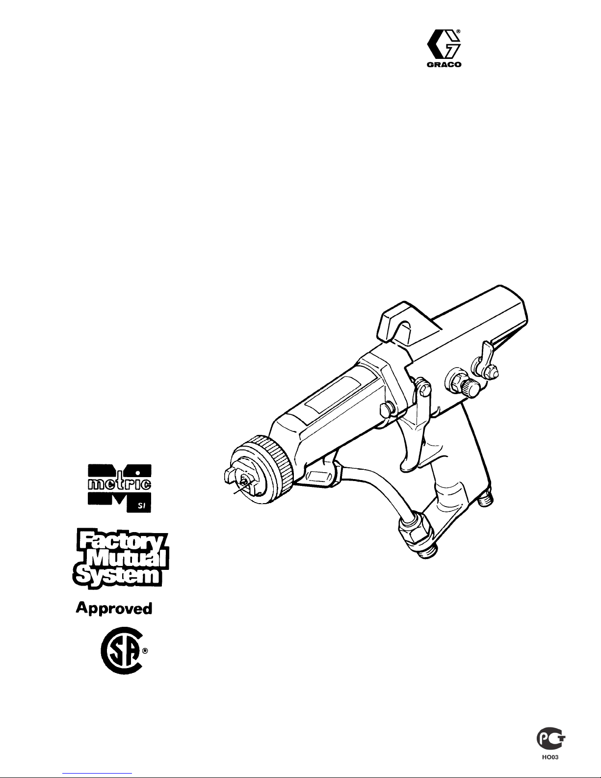
Model
MANUAL MID-RANGE ELECTROST
AIR-ASSISTED
66
7 bar (100 psi) MAXIMUM WORKING AIR PRESSURE
PRO AA4000
ATIC
AIRLESS SPRAY GUN
bar (950 psi) MAXIMUM WORKING FLUID PRESSURE
Part Number 218–668, Series B
With
0.279 mm (0.01
U.S.
Patent No. 4,290,091; 4,219,865;4,386,739; 3,843,052;
4,462,061; 4,497,447; 4,554,622
U.K. Patent No. 2,140,327B; 2,111,406B; 2,142,559B; 2,147,158
Patented 1986, 1987 Canada
Brevete 1986, 1987
French Patent No. 82 21202; 84 07942; 84 10234
Italian Patent No. 1,1
W
est German Patent No. DE 22 09 896
1 in.) spray tip, part no. 219–41
11,380
1
GRACO INC. P.O. BOX 1441 MINNEAPOLIS, MN 55440–1441
COPYRIGHT
1984, GRACO INC.
Page 2

Page 3

TABLE OF CONTENTS
Terms 3.
How
Safety Warnings
. . . . . . . . . . . . . . . . . . . . . . . . . . . . . . . . . . . . . . .
The Electrostatic Air-Assisted Airless
Spray Gun W
orks 3.
. . . . . . . . . . . . . . . . . . . . . . . . . .
.
. . . . . . . . . . . . . . . . . . . . . . . . . . .
Installation
Typical
Warning
Ventilate
Connect
Check
Connect
Installation6. . . . . . . . . . . . . . . . . . . . . . . . . . . . . .
Signs6. . . . . . . . . . . . . . . . . . . . . . . . . . . . . . . . .
the Spray Booth7. . . . . . . . . . . . . . . . . . . . . . .
the Air Line7. . . . . . . . . . . . . . . . . . . . . . . . . . . .
the Electrical Grounding7. . . . . . . . . . . . . . . . . .
the Fluid Line8. . . . . . . . . . . . . . . . . . . . . . . . . .
Operation
the Fluid8. . . . . . . . . . . . . . . . . . . . . . . . . . . . . . . . .
Filter
Spraying
Operating
Install
Adjust
Operation8. . . . . . . . . . . . . . . . . . . . . . . . . . . . .
Checklist8. . . . . . . . . . . . . . . . . . . . . . . . . . . . .
the Spray T
ip and Air Cap9. . . . . . . . . . . . . . . . .
the Spray Pattern9. . . . . . . . . . . . . . . . . . . . . . . .
Maintenance
Daily
Care and Cleaning
Flush
the Spray Gun
. . . . . . . . . . . . . . . . . . . . . .
. . . . . . . . . . . . . . . . . . . . . . . . . .
4, 5
10.
10.
Test
Power Supply Resistance
Test
Resistor Stud Resistance
. . . . . . . . . . . . . . . . .
. . . . . . . . . . . . . . . . .
14.
15.
Service
Disassembly
Gun
Electrode
Ball
Barrel
Barrel
Fluid
Check
Power
Turbine
Fan
Wire Replacement
Seat Housing & Resistor Replacement
Removal
Reassembly
Needle Replacement
the Gun Safety Latch
Cartridge Replacement
Alternator Removal
Air V
alve Replacement
Air Valve Replacement
ES
ON-OFF V
Muffler,
Repair
Parts
Parts List 25.
Check V
Kits
Drawing
. . . . . . . . . . . . . . . . . . . . . . . . . . . . . . . . . . .
Accessories 26–28
. . . . . . . . . . . . . . . . . . . . . . . . . . . .
. . . . . . . . . . . . . . . . . . .
. . . . . .
. . . . . . . . . . . . . . . . . . . . . . . . . . . . . .
. . . . . . . . . . . . . . . . . . . . . . . . . . .
. . . . . . . . . . . . . . . . . . . .
. . . . . . . . . . . . . . . . . . .
. . . . . . . . . . . . . . . . .
. . . . . . . . . . . . . . . . . . . .
. . . . . . . . . . . . . . . . . . . .
. . . . . . . . . . . . . . . . . . . . . . . .
alve Removal and Repair
. . . . . . . . .
alve & Inlet Filter Replacement
. . . . . . . . . . . . . . . . . . . . . . . . . . . . . . . . .
. . . . . . . . . . . . . . . . . . . . . . . . . . . . . . .
. . . . . . . . . . . . . . . . . . . . . . . . . . . . . .
. .
16.
16.
16.
17.
17.
18.
18.
19.
20.
21.
21.
22.
22.
23.
24.
Spray
Pattern T
Gun Operation Troubleshooting Chart 12.
Electrical Troubleshooting Chart 13.
roubleshooting Chart 11.
. . . . . . . . . . . . .
. . . . . . . . .
. . . . . . . .
Electrical Tests
est Gun Resistance
T
. . . . . . . . . . . . . . . . . . . . . . . . . .
14.
TERMS
WARNING:
cause
CAUTION: Alerts user to avoid or correct conditions that could
cause
NOTE:
FLUID INJECTION INJURY: A serious injury, which may ap-
pear to be a simple cut, caused by high pressure injection of
directly into the body
fluid
HOW
This gun combines electrostatic air spray and airless
spraying concepts. The air has three functions: (1) to
drive
(3)
to help control the pattern size.
The turbine generates power that the power cartridge
converts
rent
Fluid is electrostatically charged as it passes the gun’s
ionizing electrode. The charged fluid is attracted to the
grounded
all surfaces.
ing
Alerts user
bodily harm.
damage to or destruction of equipment.
Identifies essential procedures or helpful information.
THE ELECTROST
the turbine, (2) to help
to avoid or correct conditions that could
.
ATIC AIR-ASSISTED AIRLESS SPRA
atomize the paint “tails”, and
to a high voltage current. The high voltage cur
charges the gun’
work piece,
s ionizing electrode.
wrapping around and evenly coat
Technical
Graco
Spray T
Warranty Back
PRESSURE RELIEF PROCEDURE: A safety procedure for
relieving
FOR
warnings
ES ON-OFF VALVE:
gun,
the
on or of
er
Data
Phone Numbers
ip Selection Chart
air and fluid pressure in the system.
YOUR SAFETY: Alerts user to read
on the page indicated.
above the gun handle, that turns the electrostatic pow
f.
. . . . . . . . . . . . . . . . . . . . . . . . . . . . . .
. . . . . . . . . . . . . . . . . . . . . .
.
. . . . . . . . . . . . . . . . .
.
. . . . . . . . . . . . . . . . . . . . . . . . . . .
the additional safety
An on/of
f switch located near the rear of
Y GUN WORKS
The
spray tip shapes the fluid into a fan pattern, similar to
a
conventional airless spray tip, but at a lower pressure.
Air
from the air cap further atomizes the
the paint tails into the pattern. The fan adjusting knob
controls
-
Note that the air-assisted airless spray gun differs from
the
the width of the pattern.
conventional air spray gun in that increasing
air reduces the pattern width. To increase the pattern
less fan air or a larger size tip must be used.
width,
-
fluid and pushes
29.
29.
30, 31
Cover
-
the fan
Page 4

SAFETY
W
ARNINGS
SERIOUS
BODIL
Y INJURY, EXPLOSION, FIRE, OR ELECTROSTATIC SHOCK CAN
OCCUR IF THE PRECAUTIONS BELOW ARE NOT FOLLOWED.
READ
UNDERST
AND ALL INSTRUCTION MANUALS, T
AGS, AND W
AND
LABELS BEFORE OPERATING EQUIPMENT.
ELECTROSTATIC EQUIPMENT SHALL ONLY BE INSTALLED AND USED BY
TRAINED,
QUALIFIED
PERSONNEL WHO SHALL BE FULL
Y CONVERSANT WITH
THE REQUIREMENTS STATED WITHIN THIS INSTRUCTION MANUAL.
FLUID
General
This
leaks or ruptured components can inject fluid through your skin and into
your body and cause extremely serious bodily injury
for
amputation. Also, fluid injected or splashed into the
can
cause serious damage.
NEVER point the spray gun at anyone or at any part of the body
NEVER put hand or fingers over the spray tip.
NEVER try to “blow back” paint; this is NOT an air spray system.
NEVER try to stop or deflect leaks with your hand or body
ALWAYS
or
removing the spray tip or servicing any system equipment.
BE
SURE equipment safety devices are operating properly before each
use.
Medical
If
any fluid appears
CARE AT
exactly
Note
is
not
exotic coatings injected directly into the blood stream. Consultation
with
able.
Spray
Be
sure all gun safety devices are operating properly before each use.
DO
NOT remove or modify any part of the gun;
tion
and result in serious bodily injury
Safety
Whenever
safety latch in the closed or “locked” position, making the gun
inoperative.
ing
of the gun.
Set
the safety latch by depressing it on the left or right side of the trigger
See
trigger
INJECTION HAZARD
Safety
equipment generates very high fluid
follow the
Pressure Relief Procedure
Alert – Airless Spray W
to penetrate your skin, get
ONCE. DO NOT TREA
what fluid was injected.
to Physician:
important to treat the injury surgically as soon as possible.
delay treatment to research toxicity
a plastic surgeon or reconstructive hand surgeon may be advis
Injection
Gun Safety Devices
Latch
you stop spraying, even for a moment, AL
Failure to set the safety latch can result in accidental
the illustration below
and up.
Safety
Latch
shown in
or
“Lock”
. Disengage the latch
closed
position
SPRAY
LOCK
pressure. Spray from the gun,
, including the need
eyes or on the skin
.
, at right, before cleaning
ounds
T AS A SIMPLE CUT. T
into the skin is a traumatic injury
EMERGENCY MEDICAL
. T
oxicity is a concern with some
this can cause a malfunc
.
by pushing it toward the
ell the doctor
WAYS
set the gun
Safety Latch
shown in
“Spray”
open
position
trigger
.
Do
or
SPRAY
LOCK
Diffuser
The
gun dif
fuser
and
reduces the risk of fluid injection when the spray tip is not installed. T
check
dif
then
remove the spray tip.
the
turbine air OFF
gun.
If the fluid emitted is not dif
ball
seat housing.
Spray T
Use
extreme caution when cleaning or changing spray tips. If the
tip
clogs while spraying, engage the gun safety latch immediately
the Pressure Relief Procedure,
NEVER
pressure
Pressure
To
reduce the risk of serious bodily injury
ing
in the eyes or
shock,
always follow this procedure when shutting off the system, when
checking or servicing any part of the spray system, when installing,
cleaning
1.
.
It
-
-
-
.
Engage the gun safety latch.
2. T
urn the ES On–Off valve lever to OFF
urn of
3. T
4.
Disengage the gun safety latch.
5. Trigger
pressure.
6. Open
the
drainage.
7. Leave
If you suspect
has
been fully relieved
loosen the air cap retainer or hose end coupling and relieve pressure
gradually,
Bleed-Type
These
two accessories are required in your system to help reduce
risk
of serious bodily injury
and
injury from moving parts if you are
The
bleed-type air shutoff valve
and
the pump after the air regulator is
pump
to cycle unexpectedly
pump.
The
fluid drain valve
pump,
hose and gun; triggering the
sufficient.
, which is part of the ball seat housing, breaks up spray
fuser operation, follow the
Aim the gun into a
, and using the
Pressure Relief Procedure
lowest possible pressure, trigger the
fused into an irregular
ip Safety
then remove the spray tip to clean it.
wipe of
f build-up around the spray tip or remove the spray tip until
is fully relieved and the gun safety latch is engaged.
Relief Procedure
on the skin, injury from moving parts or electrostatic
or changing spray tips, and whenever you stop spraying.
f the air and fluid supply to the gun.
the gun into a
the pump
the pump drain valve open until you
that the tip or hose is completely clogged, or that pressure
then loosen completely
grounded
drain valve, having a waste container ready to catch
after following the steps above, VER
Air Shutoff V
, including splashing in the eyes or on the skin
. Locate the valve within easy reach of the
assists in relieving fluid pressure in the
, including fluid injection, splash
metal waste container to relieve
. Now clear the tip or hose.
alve and Fluid Drain V
adjusting or repairing the pump.
relieves air trapped between this valve
shut of
gun to relieve pressure may not be
ARNING
grounded
stream, replace the
.
are ready to spray again.
f. T
rapped air can cause the
, below
metal pail. With
spray
. Follow
Y SLOWL
alve
displacement
fluid
the
o
,
-
Y
4307-706
Page 5

EQUIPMENT MISUSE HAZARD
General
Any
surizing,
ing
injection,
NEVER
to
malfunction.
CHECK
aged
Read
the
Safety
misuse of the spray equipment or accessories, such as overpres
modifying parts,
worn or damaged parts, can cause them to rupture and result in fluid
electrostatic shock, fire, explosion or property damage.
alter or modify any part of this equipment; doing so
all spray equipment regularly and repair or replace worn or dam
parts immediately
and follow the fluid and solvent manufacturer’s literature regarding
use of protective clothing and equipment.
using incompatible chemicals and fluids, or us
could cause it
.
FIRE, EXPLOSION, or ELECTROSTA
To
reduce the risk of fire, explosion, or electrostatic shock, which may re
sult
from electrical discharge, it is essential that:
S
All parts of the electrostatic system are properly grounded.
S
All personnel in or close to the spray area are properly grounded.
S All electrically conductive objects or devices in the spray area,
including paint containers, wash cans and tools, are properly
grounded.
When
operating the electrostatic device, any ungrounded objects in the
spray
area (such as people, containers, tools, etc.) can become
cally
charged. Arcing may occur if these objects then come in contact or
close to ground. Arcing of sufficient energy levels can ignite the fluid
being
sprayed, fumes from solvents, dust particles, and other flammable
substances.
ily
injury and property damage.
Static electricity can also be generated by the
pump,
ing
as described in
If
you
ING
sure
This can cause a fire or explosion and result in serious bod
hose, gun, and nozzle, but it is dissipated through proper
experience any arcing or feel even a slight shock, STOP SPRA
IMMEDIA
you have corrected the problem before starting to spray again.
Grounding
TELY
. Check for proper grounding of the entire system. Be
below
flow of fluid through the
.
Grounding
The
following are
static system. Your system may include other equipment or objects
which
must also be grounded. Always check your local electrical code for
detailed
grounding instructions. Be sure your systemis connected to a
true
earth ground.
1.
Pump:
separate
2.
Air
compressors and hydraulic power supplies:
the
manufacturer’s recommendations.
3.
Electrostatic
properly grounded air
Conductive
Connect
4.
Object being sprayed:
grounded
edges.
All electrically conductive objects or devices
5.
including paint containers and wash cans, must be properly
grounded.
minimum
ground
by using a ground wire and clamp as described in your
pump instruction manual.
Spray Gun:
Air
the air hose ground wire to a true earth ground.
at all times. Contact points must be sharp points or knife
requirements for grounding a basic electro
ground according to
obtain grounding through connection to a
supply hose. Use only the Graco Electrically
Supply Hose; see
keep the work piece hangers clean and
ACCESSORIES
in the spray area,
electri
ground
Y-
section to order
System
-
This
-
exceed
nent
Fluid
BE
“Wetted Parts” shown in the TECHNICAL DATA on page 29. Always
read
or
Pressure
gun has a maximum fluid working pressure of 66 bar (950 psi). Never
the maximum working pressure of the
or accessory used in the system.
gun or any other compo
Compatibility
SURE all fluids and solvents used
the fluid and solvent manufacturer’s literature before using the
solvent in this gun.
are chemically compatible with the
TIC SHOCK HAZARD
6.
-
-
-
-
-
.
All
persons entering the
soles,
such as leather
Rubber
or plastic soles are not conductive. The operator must not
wear gloves which insulate the hand from spray gun. The gloves
must
be conductive or modified as shown on page
The floor of the spray area
7.
grounded. Do not cover the floor with cardboard or any
non–conductive
Flammable liquids
8.
grounded
one
9.
All solvent pails:
conductive. Do not place the pail on any non-conductive surface,
such as cardboard or paper, which would interrupt grounding
continuity.
10.
All
containers. Do not store more than the quantity needed for
shift.
air and fluid lines
spray area:
, or personal grounding straps must be worn.
must be electrically conductive and
material which would interrupt grounding
in the spray area must be kept in approved,
use only grounded metal pails, which are
and electric cables
shoes must have conductive
must be properly grounded.
Flushing and Cleaning Safety
To
reduce the risk of static sparking or splashing, always
sure
Relief Procedure
ing.
Be
sure the ES valve lever is OFF before flushing or cleaning any
part
of the spray system.
Use
the lowest possible pressure to
metal
waste container
To flush or purge equipment,
equal
to or greater than that of the fluid being sprayed.
To
clean the exterior of the equipment,
point
of higher than 38
ALWAYS remove all solvent from the system before reactivating the
spray
gun.
Use
only non-sparking tools to clean residue from the booth and
Ventilate
To
prevent hazardous concentrations
spray
gun
Check and follow all National, State and Local codes regarding air
exhaust
codes
the Spray Booth
only in a properly ventilated spray booth. NEVER operate the spray
unless the ventilating fans are operating.
velocity requirements. Check and follow
and OSHA standard 1910–107(b)(5)(i).
on page 4 and remove
.
_ C
flush. T
ALWAYS use solvents with a flash point
(100_ F).
the spray tip before flush
rigger the gun into a
ALWA
YS use solvents with a flash
of toxic and/or flammable vapors,
all local safety and fire
8.
continuity
follow the
grounded
hangers.
fluid
Pres-
-
.
-
HOSE SAFETY
Highly
pressurized fluid contained in the hose can be very dangerous. If
the
hose develops leak, split or rupture, due to any kind of wear
or misuse, high pressure spray emitted from it can cause a fluid injection
injury
or other serious bodily injury or property damage.
TIGHTEN
fluid can dislodge a loose coupling or allow high pressure spray to be
emitted
United States Government safety standards have been adopted under the Occupational
General Standards, Part 1910.107 and any other appropriate regulations––should be consulted in connection with the installation, operation, and
maintenance of electrostatic spray painting equipment.
all fluid connections securely before each use. High pressure
from the coupling.
, damage
IMPORTANT
NEVER
use a damaged hose. Before each use, check the entire hose
cuts, leaks,
couplings.
DO
other
HANDLE
move
with
abrasion,
If any of
NOT try to recouple high pressure hose or mend it with tape or any
device. A repaired hose cannot contain the high pressure fluid.
AND
equipment. Do not use fluids or solvents which are not compatible
the inner tube and cover of the hose.
Safety and Health Act. These standards––particularly the
bulging cover
these conditions exist, replace the hose immediately
ROUTE HOSES CAREFULLY. Do not pull on hoses to
, or damage or movement of the hose
307-7065
for
.
Page 6
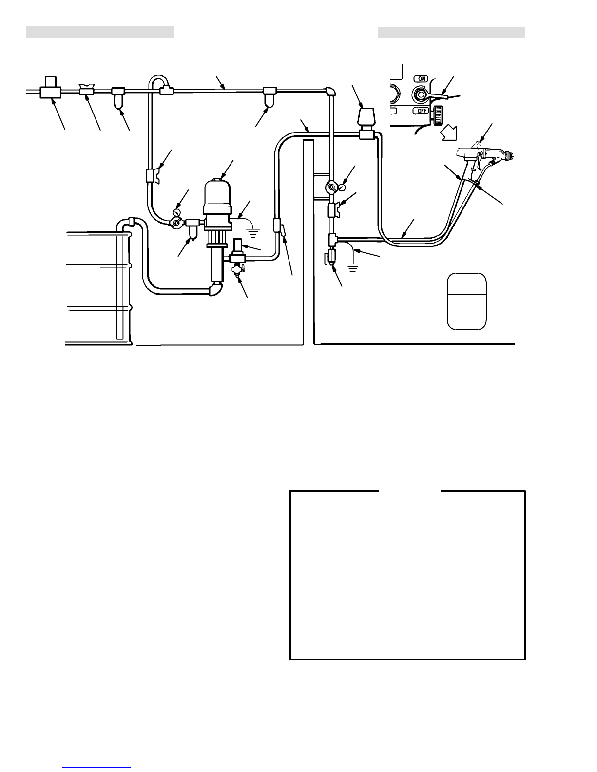
TYPICAL INSTALLATION
B* C* D
A
E*
G
F
NON–HAZARDOUS
O
H
J*
V*
AREA
M
T
N
G
W
S
P
R*
X
K
Q*
L
U
WARNING
SIGN
HAZARDOUS AREA
Air
Supply to Gun MUST Be Interlocked
W
ith Spray Booth Exhaust Fan.
KEY
A Main
B* V
C*
D
E*
F
G
H Pump
Air Supply Line
entilation Fan Interlock Solenoid V
Main Air Supply Shutof
Air & W
ater Separator
Pump Air Supply Shutof
Air Line Lubricator
Air Pressure Regulator
alve
f V
alve (bleed–type)
f V
alve (bleed–type)
J*
K
L
M
N
O
P
The Typical Installation shown above is only a guide for
selecting and installing an electrostatic air-assisted airless
spray system. It is not an actual system design.
The
particular type and size system for your operation must
be custom designed for your needs. For assistance in
designing
a system, contact your Graco representative.
The pump you use should have a maximum working
pressure of 66 bar (950 psi). If the pump you are using
has a higher maximum working pressure, a regulator
MUST be used to limit the pressure to 66 bar (950 psi).
Graco’s
be
10:1
Ratio Monark Pump, part no. 217–523, may
used in this system. See
ACCESSORIES.
Warning Signs
Mount warning signs in the spray area where they can
easily
be seen and read by all operators. An English
a Spanish Warning Sign are provided with the gun.
Additional
are
tion
English, French, German,
available at no charge. See the
to order them.
and Spanish signs
ACCESSORIES
and
sec
*Equipment that must be installed for safe operation. Must be
purchased separately
V
alve (B) is not offered as a Graco accessory
Pump Ground Wire
Fluid Filter
Fluid Supply Line Shutof
Fluid Pressure Regulator
Fluid Supply Line
Air Filter (5 micron)
Air Supply Line
Shutof
f V
alve
Installing and servicing this equipment requires
access
or
to parts which may cause electrostatic shock
other serious bodily injury if work is not performed
properly. Do not install or service this equipment
unless you are trained and qualified.
Be sure your installation complies with National,
State
and Local codes for the
apparatus in a Class 1, Group D, Divisions 1 and 2
Hazardous
Check and follow all local safety and fire codes,
NFPA 33, NEC 504 and 516, and OSHA standard
1910.107.
-
f V
alve
Location.
. See ACCESSORIES. NOTE: Solenoid
Q*
Air Hose Ground Wire
R*
Grounded Air Supply Hose
S
Electrostatic Spray Gun
T
ES On–Of
U
Air Line Drain V
V*
Fluid Drain V
W
Gun Air Inlet
X
Gun Fluid Inlet
.,
f V
alve Lever
alve
alve
WARNING
installation of electrical
Page 7
INSTALLATION
Ventilate the Spray Booth
WARNING
prevent hazardous concentrations of toxic
To
flammable vapors, spray only in a properly ventilated spray booth. Never operate the spray gun
unless ventilation fans are operating. The air
supply to the gun must be electrically interlocked
the ventilators to prevent operation
with
supply unless ventilating fans are running.
er
Check and follow all the National, State and Local
regarding air
codes
NOTE: High
velocity air exhaust will decrease the oper
exhaust velocity requirements.
ating efficiency of the electrostatic system. The
minimum
ear
Connect the Air Line (See T
allowable air exhaust velocity is 31 lin
meters/minute (100 ft/min).
ypical Installation)
WARNING
To reduce the risk of electrostatic shock or other
bodily
injury
serious
electrically
connected to
, the Air Supply Hose must be
a true earth ground.
only Graco Electrically Conductive Air Supply
Hose.
See
ACCESSORIES.
1. Connect
supply
fitting has a left hand thread.
let
ply
hose ground wire (Q) to a true earth ground.
the air supply hose (R)
line and the gun’
s air inlet (W).
Connect the air sup
2. Install an air line filter (O) and an air and water
separator
(D) on the air line to
ensure a dry
supply to the gun. Dirt and moisture can ruin the
appearance of your finished workpiece and can
cause
the gun to malfunction.
and/or
of the pow
-
Use
between the air
The
gun air in
, clean air
Check the Electrical Grounding (See Fig 1)
WARNING
Proper electrical grounding of every part of your
system is essential. For your safety, read the
warning section, FIRE, EXPLOSION, or ELEC-
TROSTATIC SHOCK HAZARD, on page 5.
Ground the system as explained there. Then
your system as explained below
check
1. Turn
the ES On–Of
the location of the valve lever
urn of
-
2. T
f the air and fluid supply to the gun.
3. Have a qualified electrician check the electrical
-
grounding
continuity of the spray gun and air hose.
a. With the electrically conductive air hose (BB)
connected (see Connect the Air Line) and
properly
measure
grounded, use a
the
(Y) and a true earth ground (Z). Use an applied
voltage
mum
of 500 volts
.
See Fig 1.
b. If the resistance is greater than 2 megohms,
check the tightness of the ground connections,
-
-
and be sure the air supply hose ground wire is
connected to a true earth ground. If the resistance is still greater than 2 megohms, replace
the
air supply hose.
Z
f valve to OFF
.
megohmmeter (AA) to
resistance between the gun handle
minimum
to 1000 volts
AA
.
. See Fig 5 for
maxi-
3. Install
and
pump
a bleed-type air regulator (G) on the pump
gun air supply lines to control air pressure to the
and gun.
4. Install a bleed-type air shutoff valve (C) on the
main
air line and pump air line (E) to shut of
pump.
Install an additional bleed-type valve on
pump air supply line to relieve air trapped between
this
valve and the
pump after air regulator is shut of
WARNING
bleed–type air shutoff valve
The
system to relieve air trapped between this valve
and the pump after the air regulator is closed.
Trapped air can cause the pump to cycle unexpectedly, which could result in serious bodily in-
including splashing in the eyes or on the skin
jury,
and
injury from moving parts.
5. Install an air line lubricator (F) as close to the
pump
(H) as possible.
6. Install an air shutoff valve (P) on each gun air
supply
line to shut of
f air to the gun(s).
f air to the
each
is required in your
BB
f.
KEY
Y Gun
Z T
AA Ohmmeter
BB
Y
Handle
rue Earth Ground
Grounded Air Hose
Fig 1
Page 8
INSTALLATION
Connect the Fluid Line (See T
ypical Installation)
1. Before connecting the fluid line (N), blow it out
with
air and flush it with
compatible
2. Install
fluid pressure to the gun.
trol
with the fluid to be sprayed.
a fluid regulator (M) on the fluid line to con
solvent. Use solvent which is
3. Install a fluid filter (K) and drain valve (V) at the
pump
outlet.
4. Connect fluid line to 1/4–18.6(m) gun fluid
inlet (X).
OPERATION
WARNING
For your Safety,
Procedure
Relief
system, when you stop spraying, and before
checking,
any
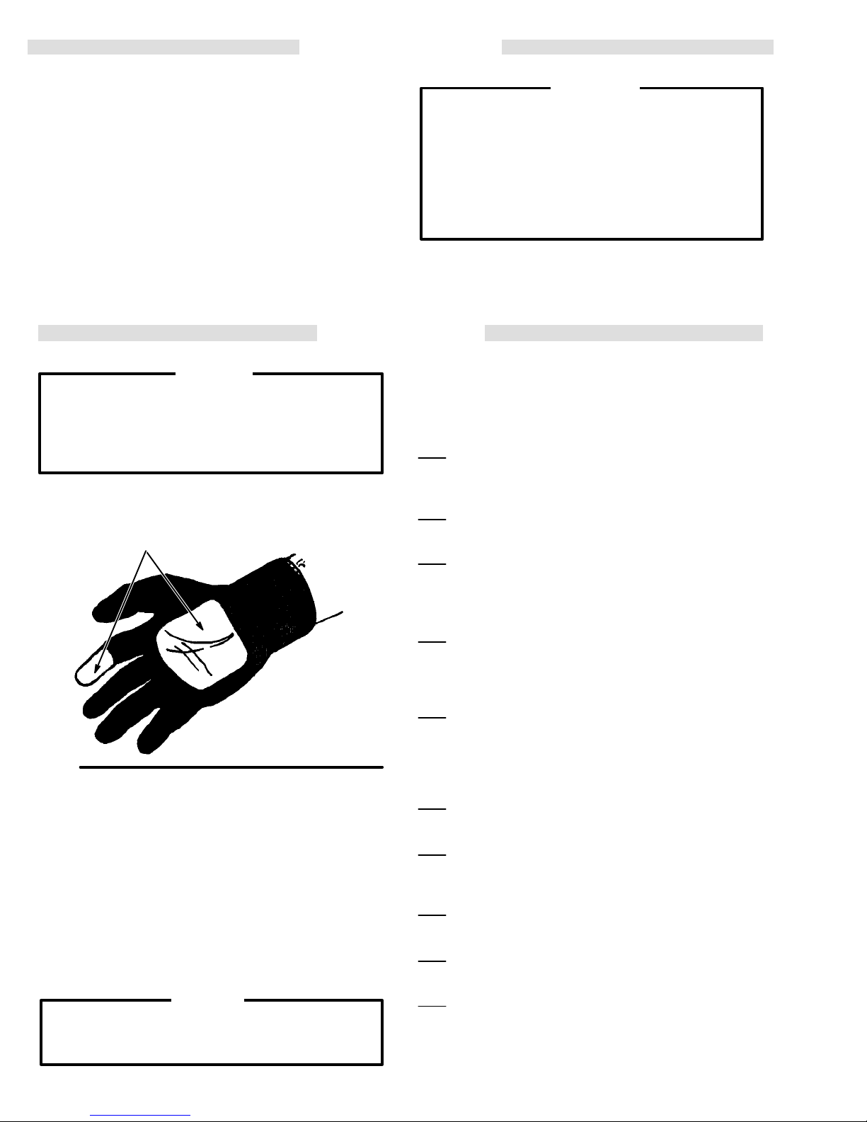
Square Cut Out
servicing, installing,
part in the system.
3
in. (76 mm)
and Finger of
Glove Cut Off
ALWAYS follow the Pressure
on page 4 when shutting off the
cleaning or chaning
NOTE:
If gloves are
be
conductive or modified as shown
so as not to interfere with operator
grounding
through the gun.
worn, they must
WARNING
The
fluid drain valve
assist
in relieving
(V) is required in your system to
fluid pressure in the displacement
pump, hose and gun; triggering the gun to relieve
pressure may not be sufficient. The drain valve
-
reduces
ily
Install
the risk of property damage or serious bod
injury
, including
splashing in the eyes or on skin.
a drain valve close to the pump’s fluid
Operating Checklist
Check the following list daily, before starting to operate
the system, to help ensure you of safe, efficient
operation.
1. Be sure all operators are properly trained to
safely operate an air-assisted airless electro-
spray system.
static
2. Be
sure all operators are trained how to prop
and completely relieve system pressure.
erly
3. Be sure the system is thoroughly grounded.
See FIRE, EXPLOSION, or ELECTRIC
SHOCK HAZARD, page 5, and Check the
Electrical Grounding
, page 7.
-
oulet.
-
Fig 2
Filter the Fluid
Filter the fluid to remove coarse particles and sediment
could clog the spray nozzle.
which
Spraying Operation
This gun has a built-in lead and lag operation. The gun
begins emitting air before the fluid is discharged. When
release the trigger
you
stops.
This helps prevent fluid buildup on the air cap.
When
spraying, the ES indicator lights (44) should
indicating
the electrostatic charge. See Fig 5.
Be careful not to damage the electrode by jamming it into an object when operating or setting
the gun.
down
, the fluid
CAUTION
stops before the air flow
glow
4. Be
sure the operator and all persons entering
the
spray area are properly grounded by
wear
ing shoes with conductive soles or personal
grounding
5. Operator
straps.
must not wear gloves which
insulate
the hand from the spray gun. If worn, gloves
must be conductive or modified as shown in
Fig 2 so as not to interfere with operator
grounding
through the gun.
6. Be sure ventilation fans are operating
properly.
7. Be
sure the workpiece hangers
are clean and
grounded. Contact points must be sharp
or knife edges.
points
8. Be sure all refuse is removed from the spray
booth.
,
9. Be sure all flammable liquids in spray booth
are
in approved, grounded containers.
10. Be sure all conductive objects within 20 ft
of the gun are electrically grounded and
(6 m)
the floor of the spray area is electrically conductive
and grounded.
8307-706
Page 9
OPERATION
Install the Spray Tip and Air Cap
WARNING
your safety
For
Procedure,
the spray tip or air cap.
ing
1. See the
30,
to select the appropriate spray tip
cation.
spray
tip size, fluid viscosity
2. Place
ing the tab of the tip with groove in the air cap. Be
careful
5.
3. Place the air cap assembly on the gun. Screw
the
retaining nut (1
leakage between the tip and ball seat housing.
NOTE: The
direction
Operating
a bent or damaged electrode wire will impair the
electrical
electrical
fire, or explosion,
jury,
is properly installed in the
not
bent or damaged before operating the gun.
, always follow the
on page 4, before
SPRA
Y TIP SELECTION CHART
Pressure
Relief
installing, or remov
, page
-
for your appli
The fluid output and fan width
depends on the
, and fluid pressure.
the spray tip (13) in the air cap (12), align
not to damage electrode wire (GG). See Fig
1)
firmly
onto the gun to prevent
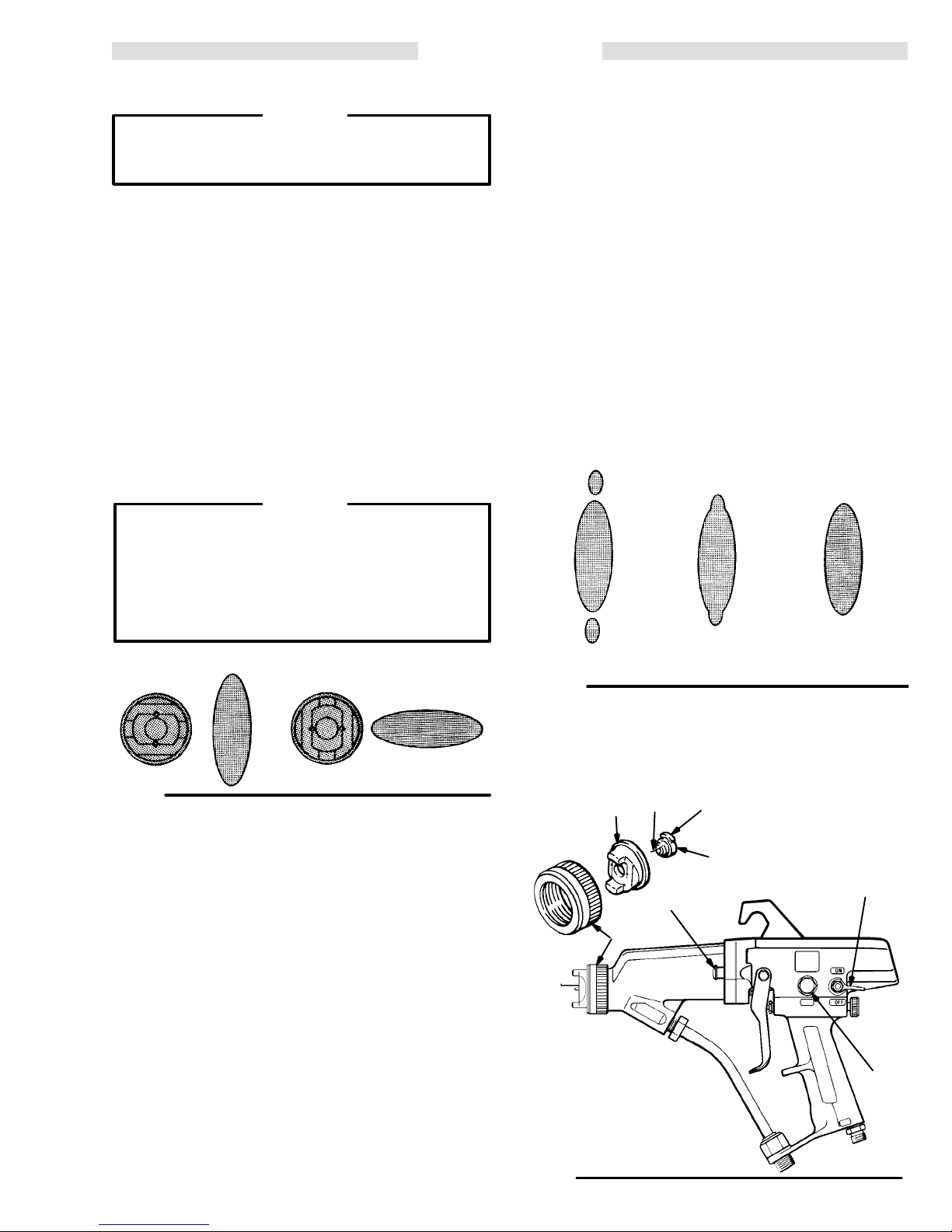
air cap and spray tip position determines the
of the spray pattern. See Fig 3.
WARNING
the gun without the electrode
continuity of the gun. T
discharge,
which could cause serious in
BE SURE
o reduce the risk of
gun
(see page 16) and is
wire or with
-
the electrode wire
6. First,
-
-
7. Check
8.
complete all the checks under the
ing
Checklist
valve
lever (T) to ON. See Fig 5.
on page 9. Then turn the ES ON-OFF
Operat-
Provide a 3.1 bar (45 psi) clean, dry, regulated air
supply to the gun to ensure full voltage from the
power supply. The gun may be operated at lower
turbine
air pressure,
but may lose some electrostatic
effect. Do not operate the turbine at an air pressure
greater
turbine
than 3.1 bar (45 psi) as there is no benefit and
life will be reduced.
the spray pattern,
then adjust the air pres
sure until all the tails are completely atomized and
pulled
into the spray pattern. Refer to Fig 4.
If a narrower pattern is desired,
fan adjusting knob (EE)
still
not narrow enough, increase the air line pressure
slightly
or use a dif
clockwise
ferent size tip.
try turning the
. If the pattern is
-
VERTICAL
SPRA
Y P
ATTERN HORIZONT
AL SPRA
Y P
ATTERN
Fig 3
Adjust the Spray Pattern
Follow
the steps
and
air flow. DO NOT
1.
Set the fluid pressure at about 21
using the fluid regulator
2. Trigger the gun to check the atomization; don’t
be
concerned about the pattern shape yet.
3. Increase the fluid pressure just to the point that
any
further increase in fluid pressure does not signifi
cantly
bar
(950 psi) fluid pressure.
4. Be sure the fan adjusting knob (EE) is closed
(turned
below to establish the correct fluid flow
turn the electrostatics on yet.
bar (300 psi),
.
improve fluid atomization. DO NOT exceed 66
fully
counterclockwise
).
-
NO AIR
Fig
4
KEY
11 Retaining
12
Air Cap
13
Spray T
44
ES Indicator Lights
ip
12
Nut
11
OO LITTLE AIR
T
GG
44
Tab
13
RIGHT AMOUNT
T
ES ON-OFF
V
alve Lever
EE
Fan Adjusting Knob
GG
Electrode Wire
OF AIR
T
EE
5. Set
the atomizing
air pressure to 3.1 bar (45 psi).
Fig 5
307-7069
Page 10
MAINTENANCE
Daily Care and Cleaning
CAUTION
Clean all parts with a non–conductive solvent,
compatible with the fluid being sprayed. Conductive
solvents can cause the gun to malfunction.
Methylene chloride
flushing
or cleaning solvent with this gun as it will
damage nylon components.
Do not use any cleaning method which may
allow solvent into the gun air passages.
Immersing
the gun
as a cleaning method. Solvent left in gun passages
could
result in a poor quality paint finish and may
draw current and reduce the electrostatic effect.
Solvent
ternator
in the power supply cavity can
life.
For your safety,
Procedure
lief
when you stop spraying, and before checking,
tem,
servicing,
in
the system.
installing, cleaning or
is not recommended as a
in solvent is not recommended
reduce al
WARNING
always follow the Pressure Re-
on page 4 when shutting of
f the
changing any part
sys
c. Use a soft brush or other soft tool, with an air
blow gun, to clean air cap passages. Take care
not to scratch any surfaces. If air cap holes are
plugged, use a round toothpick to unplug the
holes.
CAUTION
Do
not use metal tools to clean the air cap holes as
this may scratch them, and make sure the elec-
wire is not damaged. Scratches in
trode
holes
or a damaged electrode wire can distort the
spray
pattern.
6. Check
the electrode wire. Straighten
the air cap
if bent, and
replace if broken or damaged. See Electrode Wire
-
Replacement.
KEY
25 Fluid
26
Inlet Fitting
Fluid Filter
-
26
1.
Clean the fluid and air line filters daily
.
2. Check all of the work hangers for build-up of
material;
3.
a.
b. Remove
c. Reinstall
clean them, if necessary
Clean the gun fluid filter (26) daily
.
. See Fig 6.
Unscrew and remove the fluid inlet fitting (25).
the filter (26) and clean thoroughly in a
compatible
non-conductive solvent.
the filter and inlet fitting. DO NOT over
tighten the inlet fitting as over tightening could
distort
4. Clean
dampened
the filter
the outside of the gun daily with a soft cloth
in a compatible solvent.
.
5. Clean the air cap and spray tip daily, minimum.
Some applications require more frequent cleaning.
Replace
a.
b. Clean
spray tip and air cap if they are damaged.
Remove the air cap and spray tip.
the tip and air
with
a soft brush.
cap with solvent and scrub
Fig
6
Flush the Spray Gun
WARNING
To reduce the risk of electric shock, which could
result in serious injury, or the risk of fire or explosion the ES On-Off lever (electrostatics) must be
before flushing.
OFF
For your safety,
Procedure
Relief
Methylene chloride
flushing
or cleaning solvent with this gun as it will
damage nylon components.
1.
Follow the
2.
Disconnect and plug the fluid line.
3.
Connect the solvent supply to the gun.
Pressure Relief Procedure
always follow the Pressure
on page 4 before flushing.
CAUTION
is not recommended as a
on page 4.
25
WARNING
To avoid damaging the ball seat housing resistor,
use a soft bristle brush dipped in solvent to clean;
NOT
DO
soak it in solvent! A damaged resistor will
impair the electrical continuity and could result in
electrical discharge, which could cause serious
fire, or explosion.
injury,
10 307-706
4.
Flush the gun with solvent until it is clean.
5. Follow the Pressure Relief Procedure, then disconnect
Reconnect the fluid supply line.
6.
8. T
the solvent supply
rigger the gun until it is clear of solvent.
.
Page 11

SPRAY PA
Installing
ous
and
Pressure Relief Procedure
To reduce the risk of serious bodily injury, including
fluid injection, splashing in the eyes or on the skin,
injury
follow this procedure when shutting off the system,
when
tem, when installing, cleaning or changing fluid nozzles,
1.
2. T
3. T
4.
and servicing this equipment requires access to parts which may cause electrostatic shock or other seri
bodily injury if the work is not performed properly
qualified.
from moving parts or electrostatic shock, always
checking or servicing any part of the spray sys
and whenever you stop spraying.
Engage the gun safety latch.
urn the ES ON–OFF V
urn of
f the air and fluid supply to the gun.
Disengage the gun safety latch.
TTERN TROUBLESHOOTING CHART
WARNING
. Do not install or service this equipment unless you are trained
WARNING
alve lever to OFF
.
5. Trigger
tainer
6.
Engage the gun safety latch.
7. Open the pump drain valve, having a waste con-
-
tainer
8. Leave the pump drain valve open until you are
ready
If you suspect that the tip or hose is completely
clogged, or that pressure has not been fully relieved
after following the steps above. VERY SLOWLY
loosen the air cap retainer or hose end coupling and
relieve pressure
Now
the gun into a
to relieve fluid pressure.
ready to catch the drainage.
to spray again.
grounded
gradually
clear the tip or hose.
metal waste con
, then loosen completely.
-
-
NOTE:
Check all possible remedies in the T
PROBLEM: CAUSE
IMPROPER SPRA
PATTERN
Fluttering or spitting
spray
Irregular pattern
Pattern pushed to one
side, same side of air
cap gets dirty
T
ails in pattern
Y
Insuf
Loose or cracked coupler at fluid inlet.
Air in paint supply line
Fluid build-up or spray tip partially
plugged.
Air horn holes on defective side of Clean air horn holes with solvent
pattern partially or totally plugged.
Air horn holes partially or totally
plugged.
Insuf
Fluid pressure too low
roubleshooting Charts before disassembling the gun.
ficient fluid supply
ficient air pressure.
.
SOLUTION
.
Adjust fluid regulator or fill fluid tank.
T
ighten or repair
Check, tighten siphon hose
connections, bleed air from paint line.
Clean spray tip.
and soft brush.
Clean air horn holes with solvent
and soft brush.
Increase air pressure.
Increase fluid pressure.
.
307-706 11
Page 12

GUN OPERA
PROBLEM CAUSE SOLUTION
Air
leakage from front of
gun.
Air valve not seating properly
Air stem packing too tight. Loosen packing. See page 21.
TION TROUBLESHOOTING CHART
.
Clean, service. See page 21.
Fluid leakage from
front of gun.
“Orange Peel” finish.
Excessive spray fog.
No fluid sprays from
gun.
Equipment covered
with fluid.
Loose or worn fluid seat.
Loose spray tip.
Insuf
ficient air pressure.
Using too large of a spray tip.
Fluid poorly mixed or filtered.
Improper thinner being used.
T
oo much air pressure.
Fluid thinned too much.
Fluid low
Broken fluid needle shaft. Replace needle.
Dirty or clogged spray tip.
Damaged spray tip.
Exhaust air flow insuf
properly.
Improper distance between gun and
work piece.
.
ficient or not directed
T
ighten or replace fluid seat and/or
electrode. See page 16.
T
ighten spray tip.
Increase, use least air pressure
needed for good results.
Use a smaller size spray tip.
Remix or refilter fluid.
Use proper thinner
Reduce,use least air pressure
needed for good results.
Properly thin fluid.
Check, add if necessary
Clean spray tip. See page 10.
Check, replace spray tip. See page 9.
Check for proper CFM, check baf
and direction of air flow
Adjust distance to 203–305 mm
(8–12 in.).
.
.
fles,
.
12 307-706
Page 13

ELECTRICAL
PROBLEM CAUSE SOLUTION
TROUBLESHOOTING CHART
Poor wrap–around.
ON–OFF lever in OFF position.
*ES
*T
urbine alternator not operating
Improper distance between gun
and work piece.
Parts poorly grounded.
High booth exhaust velocity
Atomizing air pressure too high.
*Fluid resistivity too low
*Faulty gun resistance.
*Faulty resistor stud resistance. Check resistor stud resistance.
*Faulty power supply resistance. Check power supply resistance.
*Damaged electrode wire.
*Faulty turbine alternator
.
.
.
T
urn lever to ON.
Check if ES ON–OFF lever is ON.
Check air supply to gun. Check for
dirt or moisture in turbine. See
page 23.
Adjust spraying distance to
203–305 mm (8–12 in.).
Clean hangers, check for proper
ground on conveyer or track.
Reduce within code limits.
Reduce air pressure.
Check fluid resistivity with paint
meter and probe.
Check gun resistance. See page 14.
See page 15.
See page14.
Replace electrode wire.
See page 16.
Be sure plug is in place on back of
turbine alternator housing.Remove
and test turbine alternator
page 20.
. See
Operator gets mild
shock.
Operator gets mild
shock when touching
work piece.
Operator not properly grounded
or is in contact with ungrounded
object.
Gun not properly grounded.
W
ork piece not properly
grounded.
*ES indicator light not on when gun is triggered.
Be sure floor is properly grounded.
W
ear shoes with conductive soles
or wear personal grounding straps.
Be sure operator is not in contact
with or carrying any metallic items
which could build up electrical
charge. If worn, a glove must be
conductive or modified as shown
on page 8.
See
Check the Electrical Grounding,
page 7. Be sure Graco air supply hose
is being used and is properly grounded.
Clean work piece hangers. Check
for proper ground on conveyor or
track.
307-706 13
Page 14

ELECTRICAL TESTS
The
performance of
the condition of the electrical components contained
inside
the gun. The electrical tests below can
determine the condition of the power supply (3) and the
ball
housing and resistor (14) as well as
the
electrical path between components.
Use
megohmmeter 218–979 (see
an
applied voltage of 500 volts to complete these
cal
tests. Connect the leads as shown.
reduce the risk
To
fire
or explosion and result in serious bodily
including electrostatic shock, DO NOT use the
megohmmeter in the hazardous area. Remove
the
gun from the hazardous area before testing
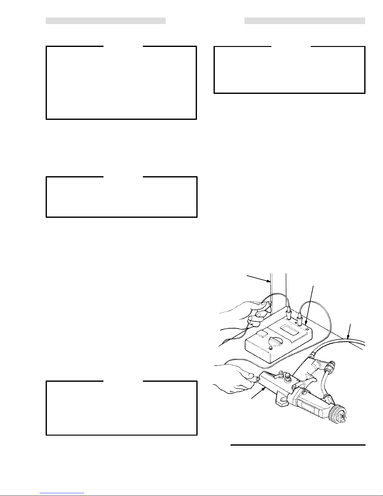
Test Gun Resistance
NOTE: Check
with
the trigger released.
the spray gun is directly af
fected by
be used to
the continuity of
ACCESSORIES
) and
electri
WARNING
of sparking, which could cause
injury
,
it.
the resistance with the gun triggered and
KEY
32 Gun
32a
A Megohmmeter
GG Electrode
-
Handle
Air Inlet Fitting
A
Measure
wire
sistance
the resistance between the end of the
(GG) and the gun air fitting (32a).
should be between 1
15–152 megohms. If the re
electrode
See Fig 7. The re
sistance is outside the specified range, go to the next
test. If the resistance is correct, refer to the Electrical
Troubleshooting Chart on page 13 for other possible
causes
of poor performance.
Test Power Supply Resistance
Remove the power cartridge (1) from the gun handle
(32).
See
Power Cartridge Replacement
Remove the turbine alternator (1a) from the power supply (3). See Turbine Alternator Removal
Measure
power
of
the power supply
the resistance from the center prong (HH) in the
supply to the
contact spring (3b) on the other end
. See Fig 8.
The resistance should be 95–122 megohms. If the
resistance
ply
is defective and must be replaced. If the resistance
the
power supply is correct, proceed to the next test.
is outside the specified range,
If you still have problems, refer to the Electrical
Troubleshooting Chart for other possible causes of
poor performance, or contact the nearest authorized
service
agency
.
.
.
the power sup
of
-
-
GG
Fig 7
KEY
3b Contact
A Megohmmeter
HH
-
Pin
Center Connector Prong
32
32a
A
Fig
HH
3b
3
8
Page 15

ELECTRICAL TESTS
Test Resistor Stud Resistance
Insert
a conductive rod (JJ) into the
for
the power supply test) and against the metal contact
(KK)
in the front of the barrel. See Fig 9.
Measure
the resistance between the conductive rod (JJ)
and the gun electrode (GG). The resistance should be
20–30
megohms. If the resistance is correct, refer to the
Electrical Troubleshooting Chart for other possible
causes of poor performance, or contact the nearest
authorized
service agency
.
If the resistance is outside the specified range, remove
the electrode wire (GG). See Electrode W
ment. Measure the resistance between the conductive
rod (JJ) and the resistor (LL) in the outside diameter of
ball
seat housing (14). See Fig 10.
The resistance should be 20–30 megohms. If the resistance
is correct, the electrode wire is defective and must
be replaced. See Electrode Wire Replacement. If the
resistance is outside the specified range, the resistor is
defective and the ball seat housing (14) must be
replaced. See Ball Seat Housing & Resistor
Replacement.
If you still have problems, refer to the Electrical
Troubleshooting Chart for other possible causes of
poor performance, or contact the nearest authorized
service
agency
.
gun barrel (removed
ire Replace
KEY
9 Gun
A Megohmmeter
JJ
KK
GG Electrode
-
Fig
Barrel
Conductive Rod
Metal Contact
GG
9
A
KK
A
9
JJ
14
Fig 10
LL
JJ
KEY
14 Ball
A Megohmmeter
JJ
LL Resistor
Seat Housing
Conductive Rod
Page 16

SERVICE
Gun Disassembly
WARNING
Installing and servicing this equipment requires
access to parts which may cause electrostatic
shock
or other serious
performed properly. Do not install or service this
equipment
unless you are trained and qualified.
Follow the Pressure Relief Procedure Warning,
page
1
1, before servicing
system.
Disconnect the fluid hose from the gun.
NOTE: Check all possible remedies in the
Troubleshooting
the
gun.
If the plastic parts of the gun must be held
securely, ALWAYS clamp them in padded vice
jaws
to prevent damage to the parts.
ALWAYS lubricate o–rings and seals with petroleum
jelly
.
ALWAYS
repair.
remove gun from worksite for service or
Service or repair area must be clean.
bodily injury if the work is not
the gun or any part of the
Charts
before disassembling
CAUTION
NOTE: A box of ten electrodes is included in the tool
kit (63).
Ball Seat Housing & Resistor Replacement
1. Unscrew
cap
(12) and spray tip (13). See Fig 1
2. Insert
gun.
While triggering the gun, unscrew the ball seat
housing (14) and remove it. See Fig 12.
3.
If
you are replacing the fluid needle assembly
not
reassemble the gun.
If
no further service is required,
ing in the reverse order of disassembly. Torque the
ball seat housing to 1.1 Nm (10 in-lb)
NOT
OVER TIGHTEN.
DO NOT over tighten the ball seat housing (14).
Excess
KEY
14 Ball
63d Wrench
Seat Housing
the retaining nut (11) . Remove the
1.
the special wrench (63d) in the
install the new hous
CAUTION
torque will damage the housing.
air
front of the
,
do
(snug)
; DO
-
Flush
the gun as described under
Flush the Spray Gun.
Follow the Pressure Relief Procedure Warning on
1
1. Disconnect the air and fluid line from the gun.
page
KEY
11 Retaining
12
Air Cap
13
Spray T
GG
Electrode Wire
ip
Nut
13
GG
12
11
Fig 1
1
Electrode Wire Replacement
1. Unscrew the retaining nut (11). Remove the air
cap
(12) and spray tip (13). See Fig 1
2. Use
trode
wire (GG) out the back of the spray tip.
a needle nose pliers
to gently pull the elec
1.
63d
14
T
orque to
1.1 N
m
(10 in-lb)
63d
14
-
3. Install the long end of the new wire in the hole
closest
to the tab of the tip. See Fig 1
1.
Push the wire
in, aligning the short end of the wire with the other
hole
in the tip. Pull on the front of the wire to seat it.
16 307-706
Fig 12
Page 17

SERVICE
Barrel Removal
1. Remove
2. Unscrew
tom
of the fluid tube (20), then pull
inlet.
See Fig 13.
3.
If
you are replacing the needle,
wrench
the gun, unscrew the ball seat housing (14) and
remove
4. Remove
5. Remove the ES indicator lights. Using the
wrench (63f) supplied, loosen and remove the two
socket head cap screws (45) from the gun. See Fig
13.
6. Hold
the
gun barrel (9) straight up to remove it. See Fig 14.
To avoid damaging the power cartridge, always
pull
the gun barrel straight up.
move
the gun barrel from side to side to free it from
the
gun handle.
the retaining nut, air cap, and spray tip.
the fluid tube connector (FF) at the bot
the tube out of the
insert the special
(63d) in the front of the gun. While triggering
it. See Fig 12.
the trigger screws,
spacers, and trigger
the gun handle (32) with one hand and pull
CAUTION
If necessary
, gently
-
.
KEY
20 Fluid Tube
20a Washer
45
Cap Screw
63f Wrench
FF
Fluid T
ube Connector
Fig 13
KEY
1
Power Cartridge
4 Gasket
9
Gun Barrel
32
Gun Handle
20
FF
63f
45
20a
9
4
NOTE: The gasket (4) should be left in the gun handle
(32)
if the gasket is not to be replaced.
Barrel Reassembly
1.
2. Be sure the gasket (4) is in place. Replace if
3. Install
4. Insert
5. If
If
the needle assembly was removed,
as
described on page 18.
damaged.
(1)
and onto the gun handle (32). See Fig 14.
Place the barrel over the power cartridge
reinstall it
the two socket head cap screws (45) and
tighten with the wrench (63f) supplied. See Fig 13.
Snap
the ES indicator lights in place
head
cap screws.
the fluid tube (20) into the fluid
gun
barrel, making sure the washer (20a) is in place,
and
tighten the fluid tube connector (FF).
over the socket
inlet of the
See Fig 13.
the ball seat housing (14) was removed, insert
the pressing tool (63c) [see Fig 15] in the front of the
gun and gently push the needle back before sliding
the trigger into place and installing the screws and
spacers.
seat
Then remove the tool
housing (see page 16).
and reinstall the ball
Fig 14
KEY
19 Trigger
44
ES Indicator Lights
63c
Pressing T
77 Screw
44
ool
32
19
77
Torque
to
1.1–1.4 N
(10–12 in-lb)
m
3
6. Install the air cap, spray tip, and retaining nut.
the gun resistance as instructed on page 14.
Test
Fig
63c
15
307-706 17
Page 18

SERVICE
Fluid Needle Replacement
1. Remove
17.
If the power cartridge comes out, carefully press
it
back into the handle.
2. Insert the narrow end of the pressing tool (63c)
through
then remove the nut (21) and the adjustment nut
(17a).
3. Press the needle assembly (17) out the front of
the
gun as far as you can with a finger
it
against a flat surface. Then use the wrench (63f) to
finish
pushing it out. See Fig 16.
4. Remove the nut (17a) from the new needle
assembly. Then install the new needle assembly
through
the pressing tool (63c) into the front of the gun and
press
to seat the needle. See Fig 17.
5. Install the new adjustment nut (17a), hex end
first,
onto the needle.
6. Use the pressing tool (63c) to press on the
needle from the front of the gun, then screw the
adjusting nut (17a) all the way to the bottom of the
threads.
the gun barrel (9) as instructed on page
the front of the gun to push the needle back,
See Fig 17.
, or by pressing
the front of the gun. Insert the narrow end of
Remove the pressing tool.
KEY
17a Adjustment
21 Nut
Pressing T
63c
Nut
ool
21
17a
Bottom of
thread
63c
Fig
17
Check the Gun Safety Latch
WARNING
to be sure the
Check
erly
each time after you change the needle. Safety
latch failure or improper use of the safety latch can
result in accidental gun triggering, which could
cause
fluid injection or splashing fluid into the
or
on skin and result in serious injury
gun safety latch works prop
.
-
eyes
7. Screw the other nut (21) firmly against the
adjustment
nut to lock them together
.
8. Reassemble the gun as described in Barrel
Reassembly.
KEY
17 Needle
17a
Adjustment Nut
21 Nut
63f Wrench
Assembly
17a
21
63f
17
Fig
16
17a
SPRAY
Trigger
touch nut (17a) when
safety latch is locked.
MUST NOT
LOCK
Fig 18
TEST
1
Engage
ger the gun. Look behind the trigger to be sure it is
engaging
and
the trigger safety latch
the nut (17a).
Then engage the latch to the left
check again. See Fig 18.
to the right, then try to trig
not
TEST 2
Disengage the trigger safety latch, and trigger the gun
gently
to see if you can feel the “lead and lag” operation,
which means the air will come on before the fluid does,
and
the fluid shuts of
f before the air does.
If the gun fails either TEST 1 or 2:
Remove the trigger and the ball seat housing. Back the
nuts
(17a, 21)
Reassemble
in
front of the trigger to make sure
If
the trigger still fails any of
assembly
away
from the bottom of the threads.
and check T
ests 1 and 2 again. Also check
the needle still moves.
these tests now
,
the needle
(17) is out of tolerance and must be replaced.
-
Page 19

KEY
1 Power
1a T
1b O–Rings
1c Plug
3a O–Ring
3b Spring
3c O–Ring
4 Gasket
9 Barrel
9b Cushion
32
Cartridge
urbine Alternator
Gun Handle
SERVICE
3c
3
3a
9
4
3b
9b
See
NOTE
step 3, below
1b
after
.
NOTE:
The power cartridge (1)
includes items 1a–1c,
and 3a–3c.
Fig
19
Power Cartridge Replacement
1. Remove the barrel as described under Barrel
Removal.
the
2. Remove
The power cartridge is fragile. Be careful when
handling
it to avoid damage.
3. Grasp the power cartridge (1) with your hand.
a gentle side to side motion, pull it free from the
With
gun handle (32). Then pull the power cartridge
straight
out of the handle.
DO NOT use solvents to clean the power
cartridge
cavity in the gun handle (32). Solvent will
damage electrical components contained in the
cartridge.
power
Inspect the power cartridge cavity in the handle
for dirt or moisture. Clean out the cavity with a
clean, dry rag if necessary. Moisture and other
contaminants
gasket (4) from the gun. See Fig 19.
CAUTION
CAUTION
may damage electronic circuitry
.
1c
32
1a
NOTE: The cushion (9b) is part of the gun barrel and
should never be removed. If it ever is removed,
push the cushion, adhesive side in toward the
with a rod until it is securely adhered in the
barrel,
barrel.
DO NOT
use the power supply (3) to
press the cushion into the barrel as it will not
adhere
properly
.
4. Lightly lubricate the o–rings (1b, 3a, 3c) on the
new power cartridge with petroleum jelly. Insert the
power cartridge in the gun handle.
new
NOTE: See
5.
Fig 20 for proper alignment of the power car
tridge
(1) in the gun handle (32).
Install the gasket (4) in the gun handle (32).
6. Install the barrel on the handle as described
Barrel Removal
under
.
KEY
1 Power
32
Cartridge
Gun Handle
32
1
-
All the o–rings (1b, 3a, 3c) and the compression
spring (3b) must be in place or the gun will
malfunction.
Fig 20
Page 20

SERVICE
Turbine Alternator Removal
1. Remove the power cartridge from the gun
handle as described under Power Cartridge
Replacement.
2. Carefully twist the turbine alternator (1a)
terclockwise
and pull it of
f the power supply (3) until
just disengaged from the coupling (MM). Then continue to slowly pull the turbine alternator away from
the power supply, disconnecting the 3-wire
tor (NN). See Fig 21.
3. Using
an ohmmeter
, test the coil in the turbine al
ternator (1a). Measure the resistance between the
two outer terminals of the 3-wire connector (NN).
resistance should be 3 to 5 ohms. If the reading
The
varies
from this value, replace the alternator
4. Measure
the resistance between
each outer ter
minal of the 3-wire connector (NN) and the turbine
alternator
housing (1a). The resistance should be in
finite. If the resistance is not infinite, replace the
alternator.
5. Partially
connect the 3-wire connector (NN) onto
the prongs inside the power supply (3). See Fig 21.
Using a small screwdriver, push the connector onto
prongs until seated.
the
coun-
connec
.
6. Slide the turbine alternator (1a) onto the power
being
supply,
sure to align the coupling between the
power supply and the turbine alternator housing.
twist the turbine alternator
Then
clockwise
coupling.
7. Install the power cartridge in the gun handle as
-
-
described
KEY
1a Alternator
3 Power
MM Coupling
NN
Supply
3–Wire Connector
under
Power Cartridge Replacement
1a
NN
MM
-
3
-
to lock the
.
Fig 21
Page 21

SERVICE
Fan Air Valve Replacement
1. Turn
2. Place
ing (47) and remove it from the handle (32). See
Fig 22.
3. Remove
4. Rotate
til it is disengaged from the valve housing threads.
Pull the adjusting screw out of the valve housing (47).
5. Clean
damage.
terclockwise
6. Apply
threads on the end of the adjusting screw (48) and
install
left
7. When reassembling the fan air valve, lubricate
the
with
8. After
justing screw (48), back the adjusting screw out of
the
retaining
9. Apply PTFE paste to the threads of the valve
housing
the
KEY
32
Gun Handle
39
Retaining Ring
40 V
46 O-Ring
Air V
47
48
Air Adjusting Screw
the fan
adjusting knob (48) fully
clockwise
a wrench on the flats of the air valve hous
the retaining ring (39).
the air adjusting screw (48)
all the
parts and inspect them for wear or
If replacing the seal (40), unscrew it
clockwise
coun-
un
and remove it from the adjusting screw
medium grade thread sealant
a new seal (40).
(Remember the screw has a
to the small
hand thread.)
o-ring (46) and the adjusting
petroleum jelly
the retaining
.
ring (39) is installed on the ad
screw (48) threads
valve housing (47) until it bottoms out against the
ring.
(47) and install it in the handle (32). Torque
housing to 1.1–1.4 Nm (10–12 in–lb).
alve Seal
32
alve Housing
Air Valve Replacement
.
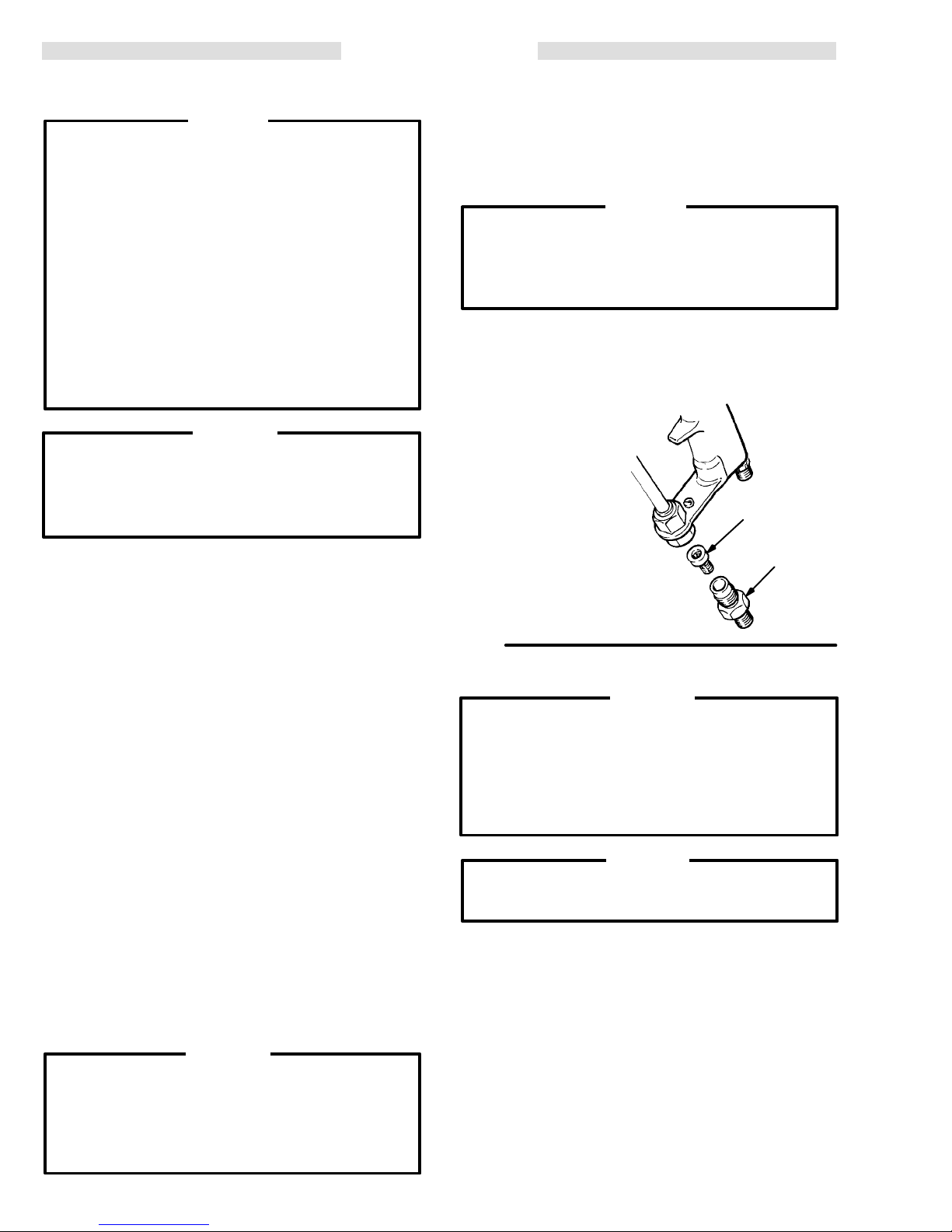
1. Using a screwdriver, remove the retainer (57),
(55), and air valve (54). See Fig 23.
spring
-
2. Remove
the
spacers from the gun.
3. Using wrench (63b), unscrew and remove the
(52) and packing (53) from the front of the gun
guide
-
handle (32).
Clean
with
ible
spirits. Use of conductive solvents can
eral
the
gun to malfunction.
.
4. Apply PTFE tape to the threads of the guide (52).
Install
the gun handle (32). Tighten the guide finger tight
only.
5. Install
the
back of the gun handle (32).
6. Apply petroleum jelly to the threads of the re-
-
tainer (57) and the o-ring (56). Install the retainer in
the back of the gun handle (32) and tighten with a
screwdriver.
7. Reinstall the trigger with the screws and spac-
ers.
8. Squeeze the trigger and tighten the guide (52)
until
just
is
released. Then loosen the guide just enough so the
valve stem returns freely when the gun is triggered
released.
and
KEY
32 Gun
52 Guide
53 Packing
54
Air V
55 Spring
56 O-Ring
57 Retainer
the trigger by removing the screws and
CAUTION
all parts in non-conductive solvent
the fluid being used, such as xylol or min
the new packing (53) and guide in the front of
the new air valve (54) and spring (55) into
the valve (54) will not return when the trigger
Handle
alve Assembly
32
Apply
PTFE
compat
cause
tape
56
57
-
-
Fig
22
40
39
47
T
orque to
1.1–1.4 N
(10–12 in–lb)
m
46
48
Fig 23
52
Apply
PTFE
tape
55
54
53
307-706 21
Page 22

SERVICE
ES
ON–OFF V
alve
Removal & Replacement
1. Loosen and remove the nut (49). Remove the
(51) and washer (50). See Fig 24. Insert the hex
lever
head
wrench (63e) into the hex end of the valve (38),
and
loosen and remove the valve.
2. Clean and inspect parts for wear or damage.
Replace
valve
if necessary
(38) with petroleum jelly
. Lubricate the o–rings (37) and
.
3. Install the regulator disc (2) so that the beveled
of the disc faces into the valve (38).
face
4. Install the valve (38) with the regulator disc (2)
o–rings (37) into the gun handle so that the larger
and
opening
the
5. Install
(49)
to
of the
valve cylinder faces toward the front of
gun handle.
the wave washer (50), lever
on the valve stem. T
0.225 Nm (2 in–lb).
ighten the nut
(51), and nut
and torque it
KEY
2 Regulator Disk
37 O–Ring
Air V
38
37
alve
2
38
49 Nut
50 W
51 V
37
ave W
asher
alve Lever
50
T
orque to
0.225 N
(2 in–lb)
51
49
m
Muffler, Check Valve, & Inlet Filter
Replacement
1. Remove
2.
Remove the screw (22).
3. Be
of the air inlet fitting (32a) are properly aligned with
bracket (28), then remove the
the
retainer (75) from the gun handle.
head
4. Pull the muffler (33) from the gun handle and
replace
5. Insert a 3.18 mm (0.125 in.) rod into one of the
in the valve check retainer (29)
holes
the
bracket (28). Be ready to catch the ball (31) and
spring (30) as the valve check retainer (29) is
removed.
6. Install a new ball (31) and spring (30) in the
bracket
into
place on the bracket.
7. Attach the bracket (28) and bulkhead retainer
to the gun handle with the screw (22).
(75)
8.
Install a new filter (26) in the adapter (24).
the fluid inlet fitting (25). See Fig 25.
sure the flats of the adapter (24) and the
bracket and bulk
with a new muf
fler.
and pry it out of
(28). Snap the valve check
retainer (29) back
flats
-
Fig
24
KEY
22 Screw
24 Adapter
25 Fluid
26
28 Bracket
29 V
30 Spring
31 Ball
32a
33 Muffler
75
Inlet Fitting
Fluid Filter
alve Check Retainer
Air Inlet Fitting
Bulkhead Retainer
22
32a
33
Apply
sealant
to outside
surface
24
75
28
31
30
29
26
25
9. Install the fluid fitting (25). There will be a small
between the hexes of the fitting and adapter;
space
do not over tighten them.
Fig 25
Page 23

REPAIR KITS
Repair
Use only
When
servicing use
Use
of other parts or any modification of the gun could alter
the
grounding continuity of the gun or cause parts to rupture
and result in serious injury, fire, explosion, electrostatic
or property damage.
shock,
Kits must be purchased separately
GENUINE GRACO P
only genuine Graco replacement parts.
ARTS AND ACCESSORIES.
WARNING
.
NOTE: The
Ref. Nos. shown in
the
best results, use all the parts in the kit, even if the old parts still look good.
the kits below correspond to the reference numbers used in the parts list on page 25. For
High Air Flow Restrictor Kit 220–493
Use
with standard air cap 223–167. Includes:
Ref
No.
Part No.
100 179–994 RESTRICTOR 2
101 107–414
102 100–172
Description Qty
SPRING, compression
BALL; 3/16” diameter
Low Air Flow Restrictor Kit 223–830*
Includes:
Ref
No. Part
100 180–763 RESTRICTOR 2
101 107–414
102 100–172
*MUST
100
No.
also order
101
Description Qty
SPRING, compression
BALL; 3/16” diameter
Air Cap 220–535
102
.
Optional Air Cap 220–535
MUST be used with Low Air Flow Restrictor Kit
223–830,
at left. Must order separately
.
Spray Gun Repair Kit 218–752
Includes:
2
Ref
2
No. Part
1b 107–106
2 107–107 REGULAT
3a 106–555
3c 177–156
4 179–387 GASKET
13a 183–459 W
2
20a 164–769 W
2
37 103–648
46 103–557
53 106–901
56 103–338
No.
MANUAL
Description Qty
O–RING, buna–N
OR, disc
O–RING, fluorocarbon
O–RING, V
ASHER, non-metallic
ASHER, PTFE
O-RING, V
O-RING, V
O-RING, PTFE
O-RING, V
iton 1
, housing
2
iton 2
iton 1
iton 1
CHANGE SUMMAR
2
1
1
1
1
1
Y
The
manual was changed from Rev
spray tip 219–407 from the SPRAY TIP SELECTION
CHART.
. P to Rev
. R to delete
Page 24

PARTS
DRA
WING
Part No. 218–668, Series B
Model PRO AA4000 Gun
*3a
3b
9b
14
13a*
13
12
11
37*
2*
43
42
41
38
37*
1b*
32
34
55
50
51
1a
*3c
3
52
53*
1
19
76
77
40
39
47
Apply
32a
–
801-21. T
3.4 Nm (25 in-lb)
33
REF 28
31
57
54
49
46*
56*
48
Loctite
orque to
30
29
*4
5
9
21
17a
REF 17
9a
45
44
17
Ref
No 63, T
ool Kit
Includes items 63a–63g
63c
63f
63d
*20a
63b
63g
63a
20
*20a
REF
22
32
28
75
24
26
25
Page 25

PARTS LIST
REF
NO. P
1 218–111 POWER CARTRIDGE; Includes
1a 217–591
1b* 107–106
2* 107–107 REGULATOR, disc 1
3 218–041
3a* 106–555
3b 178–504
3c* 177–156
4* 179–387 GASKET
5** 179–790
9 220–963
9a 176–921
9b 186–127
11 218–695 NUT
12 223–167 AIR CAP
13 219–411 SPRA
13a* 183–459
14 220–613 HOUSING, ball seat;
17 218–697
17a 176–938
19 186–473 TRIGGER 1
20 218–713
20a* 164–769
21 105–689 NUT
22 180–624 SCREW
24 180–728 RET
25 180–706 CONNECT
26 205–264 FIL
28 181–380 BRACKET 1
29 180–621 RETAINER 1
30 108–046 SPRING, compression 1
31 101–435
32 218–716
32a 179–400
33 180–623 MUFFLER 1
ART NO.
DESCRIPTION QTY
items 1a and 3
ALTERNAT
OR, turbine; Includes
item 1b
O–RING, buna–N 2
POWER SUPPLY
; Includes
items 3a. 3b, and 3c
O–RING, fluorocarbon
SPRING, compression 1
O–RING, Viton 1
, housing
LABEL, warning
BARREL, gun; Includes item 9a
PLUG, M3 x 0.5 x 6
CUSHION 1
, retaining, air cap
(see page 23 for optional
low air flow air cap)
Y TIP
, fluid; 0.279 mm (0.01
1”)
Includes item 13a. See page 30
for other part numbers
W
ASHER, non-metallic
(includes resistor)
NEEDLE, fluid; Includes item 17a
NUT
, adjustment
TUBE, fluid, nylon; Includes item 20a
WASHER, PTFE 2
, mach, hex; M4 x 0.7
, mach, cross pan hd; M5 x 12
AINER, filter
OR, fluid
TER, tip, 0.005
BALL, bearing
HANDLE, gun; Includes item 32a
FITTING, air inlet
REF
NO. P
34 104–765 PLUG,
1
37* 103–648 O-RING; Viton 2
38 181–326 VAL
1
39 105–681
40 181–383
41 100–172
ART NO.
DESCRIPTION QTY
pipe; hdls; 1/8–27 npt
VE, air
RING, retaining, external
SEAL, valve, acetal
BALL; 3/16” dia.
42 107–414 SPRING, compression 2
1
43 179–994 RESTRICTOR 2
1
44 218–179 LIGHT
45 107–100 SCREW
, indicator
, ES
, cap, socket hd;
M5 x 0.8 x 12
1
46* 103–557 O-RING, Viton 1
1
47 180–713 HOUSING, valve 1
1
48 180–714 SCREW
1
49 181–328 NUT
, adjusting
, cap; No. 10–32, nylon
50 102–268 WASHER, wave 1
1
51 181–327 LEVER, valve 1
52 180–735 GUIDE, stem 1
1
53* 106–901 O-RING, PTFE 1
54 215–890 VAL
VE, air
55 107–029 SPRING, compression 1
1
56* 103–338 O-RING, Viton 1
1
57 179–391 RETAINER, spring 1
1
58** 180–060
1
59** 180–063
1
62 180–209 COVER, gun
63 220–614 TOOL KIT
1
63a 105–749
63b 177–732
1
63c 181–095
1
63d 183–107
1
63f 107–460
1
63g 218–751
1
75 180–143 RET
SIGN, warning, English
SIGN, warning, Spanish
(not shown)
(not shown)
(not shown)
; Includes items 63a–63g
BRUSH, cleaning
WRENCH, nut, packing 1
TOOL, pressing 1
WRENCH, ball seat housing
WRENCH, barrel 1
ELECTRODES, box of 10 1
AINER, bulkhead
76 177–128 SPACER 2
77 107–400 SCREW
78** 179–791 T
, trigger
AG, warning
(not shown)
1
*Included in Repair Kit 218–752. See page 23.
1
1
**Extra warning tags, labels, and signs are available at no
charge
from Graco.
1
1
1
1
2
2
2
1
1
1
1
1
2
1
1
1
1
2
1
WARNING
When servicing use only genuine Graco replacement parts. Use of other parts or any modification
of the gun could alter the grounding continuity of
gun or cause parts to rupture and result in seri
the
ous injury, fire, explosion, electrostatic shock, or
property
damage.
-
Page 26

ACCESSORIES
Accessories must be purchased separately
Use only
NEVER
your
may rupture, causing serious bodily injury or property damage.
operate your equipment at a working pressure rating that is higher than the lowest rated component in
system. Lower rated components may not be able to withstand the pressure developed by the pump and
GENUINE GRACO P
WARNING
AIR LINE ACCESSORIES
Grounded Air Supply Hose
FM Approved
7
bar (100 psi) MAXIMUM WORKING PRESSURE
8 mm (0.315 in.) ID; 1/4 npsm(f) x 1/4 npsm(f) LH;
Color coded black
Part No.
220–444 1.8 m (6 ft)
218–100 5 m (15 ft)
218–101 8 m (25 ft)
218–102 11 m (36 ft)
218–103 15 m (50 ft)
220–119 23 m (75 ft)
220–120
Length
30.5 m (100 ft)
Grounded Air Supply Hose
FM Approved
7
bar (100 psi) MAXIMUM WORKING PRESSURE
8 mm (0.315 in.) ID; 1/4 npsm(f) x 1/4 npsm(f) LH;
Color coded gray; More flexible than black hose
Part No.
223–068 1.8 m (6 ft)
223–069 5 m (15 ft)
223–070 8 m (25 ft)
223–071 11 m (36 ft)
223–072 15 m (50 ft)
223–073 23 m (75 ft)
223–074
Length
30.5 m (100 ft)
ARTS AND ACCESSORIES.
.
Air Adapter Nipple 185–493
For connecting two or more grounded gun air supply
hoses.
1/4 npt x 1/4 npsm
(left-hand thread)
High Volume Air Regulator 206–199
0–9
bar (0–125 psi) Regulated Pressure
14 bar (200 psi) Steel Pressure Gauge
1/2 npt(f) inlet and outlet
Air Pressure Regulator 104–267
20
bar (300 psi) MAXIMUM WORKING PRESSURE
1/2 npt(f) inlet and outlet
Air Pressure Gauge 101–180
0–14
bar (0–200 psi) Regulated Pressure
Air Filter & Moisture Separator
17.5
bar (250 psi) MAXIMUM WORKING PRESSURE
For cleaning and drying air in air spray system.
20 micron element, 5 oz. bowl capacity
106–148 3/8 npt(f)
106–149 1/2 npt(f)
Grounded Air Supply Hose
100
psi (7 bar) MAXIMUM WORKING PRESSURE
8 mm (0.315 in.) ID; 1/4 npsm(f) x 1/4 npsm(f) LH;
Color coded red; Stainless steel braid ground path
Part No.
235–068 1.8 m (6 ft)
235–069 5 m (15 ft)
235–070 8 m (25 ft)
235–071 11 m (36 ft)
235–072 15 m (50 ft)
235–073 23 m (75 ft)
235–074
Length
30.5 m (100 ft)
Quick Disconnect Coupling Assy. 110–806
FM Approved
Includes a quick disconnect coupling insert, which
replaces
body
air
air inlet fitting 179–400, and
(left-hand thread)
hose.
, which connects to the grounded
a shut-of
f coupling
Air Line Lubricator
17.5
bar (250 psi) MAXIMUM WORKING PRESSURE
214–847 3/8 npt(f)
214–848 1/2 npt(f)
Bleed-type Master Air Valve 107–141
21
bar (300 psi) MAXIMUM WORKING PRESSURE
Relieves air trapped in the air line
between the paint pump air motor
and
this valve when closed. 3/4 npt
Page 27

ACCESSORIES
FLUID LINE ACCESSORIES
Fluid Hose Assemblies
FM Approved
207
bar (3000 psi) MAXIMUM WORKING PRESSURE
Nylon tube, Urethane Cover
Part No.
214–700 4.8
214–701
214–699
214–698
214–697
214–638
214–635
214–636
214–629
210–540
210–541
ID Length
mm (3/16 in)
4.8 mm (3/16 in)
4.8 mm (3/16 in)
4.8 mm (3/16 in)
4.8 mm (3/16 in)
6.4 mm (1/4 in) 0.4 m (14 in)
6.4 mm (1/4 in)
6.4 mm (1/4 in)
6.4 mm (1/4 in)
6.4 mm (1/4 in)
6.4 mm (1/4 in)
0.61 m (2 ft)
0.91 m (3 ft)
1.8 m (6 ft)
7.6 m (25 ft)
15.2 m (50 ft)
0.6 m (2 ft)
0.9 m (3 ft)
4.6 m (15 ft)
7.6 m (25 ft)
15.2 m (50 ft)
Thread Size
1/4 npsm(f)
1/4 npsm(m x f)
1/4 npsm(f)
1/4 npsm(f)
1/4 npsm(f)
1/4 npsm(f)
1/4 npsm(f)
1/4 npsm(f) x
1/4 npt(m)
1/4 npsm(f)
1/4 npsm(f)
1/4 npsm(f)
Corrosion Resistant Fluid Hose 224–551
207
bar (3000 psi) MAXIMUM WORKING PRESSURE
PTFE
tube, SST cover
6.4 mm (1/4 in.) ID, 483 mm (19 in.) long, 1/4 npsm(f)
, SST couplings
High Pressure Ball Valves
350
bar (5000 psi) MAXIMUM WORKING PRESSURE
Install
in outlets for individual fluid line control or install in
bottom
of filter bowl as fluid drain valve.
Part No.
210–657
210–658
210–659
214–037 1/4 npt(m), PTFE seals
Description
1/2 npt(m), V
3/8 npt(m), V
3/8 x 1/4 npt(m), V
iton
iton seals
seals
iton seals
PUMP & SPRAY SYSTEM ACCESSORIES
10:1 Ratio Monark Pump 217–523
66
bar (950 psi) MAXIMUM WORKING PRESSURE
Pump Suction Hose 214–960
Pail Suction Tube 165–767
Drum Suction Tube 206–266
Cart 208–210
SST Fluid Pressure Regulator 222–121
105 bar (1500 psi) MAXIMUM FLUID INLET PRESSURE
10.5–84 bar (150–1200 psi) REGULA
TED PRESSURE
SST Fluid Pressure Regulator 217–576
0–70
bar (0–1000 psi) REGULA
T
o convert Standard Fluid Pressure Regulator
206–661 to 70 bar (1000 psi) Maximum W
Pressure, order the following parts:
Part No.
501–511
101–696
Description
Compression Spring
Fluid Pressure Gauge
0–70 bar (0–1000 psi) range
TED PRESSURE
orking
Fluid Filters
207
bar (3000 psi) MAXIMUM WORKING PRESSURE
Part No.
214–570
218–029
Description
With aluminum bowl and support
With carbon steel bowl and support
Stainless Steel Screens
Part
No.
167–024
167–025
167–026
167–027
Description
595 micron (30 mesh)
250 micron (60 mesh)
149 micron (100 mesh
74 micron (200 mesh)
Wall Bracket 206–220
Electrostatic System 230–987
Includes
items:
Part No.
218–668
218–101
214–698
106–148
Description
Manual E/S Air-Assisted Airless Gun
Grounded Air Supply Hose (See
page 26 for specifications)
Fluid Hose (See page 26 for
specifications)
Air Filter
Pro AA4000 10:1 Ratio Monark Cart
System 230–984
Includes System 230–987, 10:1 Ratio Monark Pump,
and additional accessories
Cart,
Pro AA4000 10:1 Ratio Monark Pail
System 230–985
Includes
additional
system 230–987, 10:1 Ratio
accessories
Monark Pump, and
Pro AA4000 10:1 Ratio Monark Wall
Mount System 230–986
Includes system 230–987, 10:1 Ratio Monark Pump,
Bracket, and additional accessories
Wall
Page 28

ACCESSORIES
MISCELLANEOUS ACCESSORIES
Paint Resistance Meter 722–886
Used
with 722–860 Paint Probe to measure
resistance of paint.
Not for use in Hazardous areas.
Paint Probe 722–860
Used
with 722–886 Paint Resistance Meter to
measure resistance of paint.
Not for use in Hazardous areas.
Megohmmeter 218–979
500 Volt output; 0.01–2000 megohms
Not for use in Hazardous areas.
Gun Cover 218–374
Package
of 10 disposable gun covers.
Electrode Wires 218–751
Box
of 10 replacement electrode wires for spray tip.
Compression Spring 105–673
For
increased shut-of
component materials.
f force when spraying plural
Grounding Clamp And Wire 222–011
12
ga, 25 ft (7.6 m) wire
Warning Signs
FM Approved
Available
Must be ordered separately
from Graco at no extra charge.
.
Part No.
180–060 W
180–061 W
180–062 W
180–063 W
Description
arning Sign (English)
arning Sign (French)
arning Sign (German)
arning Sign (Spanish)
105–673
Page 29

TECHNICAL
DA
TA
GRACO PHONE NUMBERS
Weight 0.87
Gun
Maximum Working Fluid Pressure
Maximum Working Air Pressure
Voltage
Air
Fluid
Wetted Parts Stainless Steel, Acetal, UHMW.
Delrin
the
Loctite
.
. . . . . . . . . . . . . . . . . . . . . . . . . .
Length
Inlet
Inlet
DuPont Co.
.
. . . . . . . . . . . . . . . . . . . .
Operating Range
.
. . . . . . . . . . . . . . . . . . . . . . . .
. . . . . . . . . . . . . . . . . . . . . . . . . .
. . . . .
and V
iton
are registered trademarks of
is a registered trademark of the Loctite Corp.
AIR FLOW WITH THE FAN ADJUSTMENT SET FOR THE WIDEST PATTERN AND THE TURBINE ON
.
. . . . . . . . . . . . . . .
Polyethylene, Nylon, Carbide,
PTFE,
310 mm (12.25 in.)
66 bar (950 psi)
.
. .
.
. . . . . .
Delrin
7 bar (100 psi)
1/4 npsm(m) L.H.
16
Kg (1.90 lb)
0 to 75 KV
1/4–18.6 (m).
AIR
FLOW CHART
TO PLACE AN ORDER
or
call this number to identify the distributor closest
tor,
to
you:
FOR
TECHNICAL ASSIST
or assistance regarding the
mation
equipment: 1–800–543–0339 T
, contact your Graco distribu-
1–800–328–0211 T
ANCE
,
service repair infor
application of Graco
oll Free
oll Free
-
14
12
AIR CAP 223–167
10
8
6
AIR CONSUMPTION (SCFM)
4
AIR CAP 220–535
2
0
0 1020304050607080
NOTES:
Cap 223–167 requires use of Standard Restrictor
Air
Air
Cap 220–535
Air
flow will increase if the fan adjustment valve is opened to temporarily reduce pattern size. Flows
will
reach 24 SCFM at 80 psi (5.6 bar) with Air Cap 223–167.
GUN INLET PRESSURE (PSI)
MUST
be used with Low Air
, part no. 179–994.
Flow Restrictor Kit, part no. 223–830 (see page 23).
307-706 29
Page 30

SPRAY
TIP SELECTION CHART
Part Number
219–107
219–207
219–307
219–209
219–309
219–409
219–211
219–311
219–411
219–511
219–611
Fan Width at
300 mm (12 in.)
mm (in.)
50–100 (2–4) 0.178 (0.007)
100–150 (4–6)
150–200 (6–8)
100–150 (4–6) 0.229 (0.009)
150–200 (6–8)
200–250 (8–10)
100–150 (4–6)
150–200 (6–8)
200–250 (8–10)
250–300 (10–12)
300–350 (12–14)
Orifice Size
mm (in.)
0.279 (0.01
Light to Medium
Viscosity*
ml/min
(fl oz/min)
100 (3.4)
200 (6.8)
1) 300 (10.1)
Heavy Viscosity
liters/min ((fl oz/min)
219–213
219–313
219–413
219–513
219–613
219–215
219–315
219–415
219–515
219–615
219–217
219–317
219–417
100–150 (4–6) 0.330 (0.013)
150–200 (6–8)
200–250 (8–10)
250–300 (10–12)
300–350 (12–14)
100–150 (4–6) 0.381 (0.015)
150–200 (6–8)
200–250 (8–10)
250–300 (10–12)
300–350 (12–14)
100–150 (4–6) 0.432 (0.017)
150–200 (6–8)
200–250 (8–10)
400 (13.5)
500 (16.9)
700 (23.7) 500 (16.9)
219–517
219–617
250–300 (10–12)
300–350 (12–14)
Page 31

SPRAY
TIP SELECTION CHART
Part Number
219–319
219–419
219–519
219–619
219–719
219–421
219–521
219–621
219–721
219–821
219–423
219–523
Fan Width at
300 mm (12 in.)
mm (in.)
150–200 (6–8) 0.483 (0.019)
200–250 (8–10)
250–300 (10–12)
300–350 (12–14)
350–400 (14–16)
200–250 (8–10) 0.533 (0.021)
250–300 (10–12)
300–350 (12–14)
350–400 (14–16)
400–450 (16–18)
200–250 (8–10) 0.584 (0.023)
250–300 (10–12)
Orifice Size
mm (in.)
Light to Medium
Viscosity*
ml/min
(fl oz/min)
800 (27.0) 600 (20.3)
1000 (33.8)
1200 (40.6)
liters/min ((fl oz/min)
Heavy
Viscosity*
800 (27.0)
970 (32.8)
219–623
219–723
219–823
219–425
219–525
219–625
219–725
219–825
*Fluid Output at 41 bar (600 psi).
The
fluid output (Q)
lated
by this formula:
QT = Fluid output (fl oz/min) from the above table
Where
for
the selected orifice size.
300–350 (12–14)
350–400 (14–16)
400–450 (16–18)
200–250 (8–10) 0.635 (0.025)
250–300 (10–12)
300–350 (12–14)
350–400 (14–16)
400–450 (16–18)
at other pressures (P) can be calcu
Q= (0.041) (QT) (
P
1500 (50.7) 1200 (40.6)
NOTE: Other
-
)
Spray T
tips
are available on special work order
low
4 to 6 weeks for delivery
fice
size is 0.635 mm (0–025 in).
ip Selection Chart continued on next page.
. The maximum ori
. Al
-
-
307-706 31
Page 32

SPRAY
TIP SELECTION CHART
Round Pattern Kits
Kit Spray–Tip Tip
Part No.
222–603 222–151
222–604 222–152 0.011 (0.279)
222–605 222–153
222–606 222–154
224–045 222–159
Part No.
THE
WARRANTY
warrants all equipment manufactured by it and bearing its name to be free from defects in material and workman
Graco
ship on the date of sale by an authorized Graco distributor to the original purchaser
for
breach of this warranty
equipment proven defective. This warranty applies only when the equipment is
accordance with Graco’
, Graco
s written recommendations.
Size
in. (mm)
0.017 (0.432)
0.013 (0.330)
0.015 (0.381)
0.009 (0.229)
GRACO W
will, for a period of twelve months from the date of sale, repair or replace any part of the
ARRANTY AND DISCLAIMERS
218–695
(not included)
Kit
(see chart)
183–906
185–483
(included
Spray T
(see
185–568
for
use. As purchaser’s sole remedy
installed, operated and maintained in
ip
chart)
with tip)
-
This
warranty does not cover
misapplication, abrasion, corrosion, inadequate or improper maintenance, negligence, accident, tampering, or
lation,
substitution
incompatibility with Graco equipment of
improper
not supplied by Graco.
als
This
warranty is conditioned upon the prepaid return of the equipment claimed to be defective to an authorized Graco
distributor
any
defective parts. The equipment will be
equipment
charges
DISCLAIMERS AND LIMIT
The
terms of this warranty constitute purchaser’s sole and exclusive remedy and are in lieu of any other warranties (ex
press
non–contractual liabilities, including product liabilities, based on negligence or strict liability. Every form of liability for
direct, special or consequential damages or loss is expressly excluded and denied. In no case shall Graco’s liability
exceed
date
of sale.
EQUIPMENT NOT COVERED BY GRACO W
Graco
pose,
items
any
, of their manufacturer
these
of non–Graco component parts. Nor shall Graco be liable for malfunction, damage or wear caused by the
design, manufacture, installation, operation or
for verification of the claimed defect. If the claimed defect is verified, Graco will repair or replace free of charge
does not disclose any defect in material or workmanship, repairs will be made at a reasonable charge, which
may include the costs of parts, labor and transportation.
or implied),
the amount of the purchase price. Any action for breach of warranty must be brought within two (2) years of the
makes no warranty, and disclaims all implied
with respect to accessories, equipment, materials, or components sold but not manufactured by Graco. These
sold, but not manufactured by Graco (such as electric motor
warranties.
including warranty of merchantability or warranty of fitness for a
, and Graco shall not be liable for
structures, accessories, equipment or materials not supplied by Graco, or the
returned to the original purchaser transportation prepaid. If inspection of the
ATIONS
ARRANTY
warranties of merchantability and fitness for a particular pur
. Graco will provide purchaser with reasonable assistance in making any claim for breach of
, any malfunction, damage or wear caused by faulty
maintenance of structures, accessories, equipment or materi
particular purpose
, switches, hose, etc.) are subject to the warranty
instal
, and of any
, if
-
-
-
-
Sales
Offices:
Foreign Offices:
GRACO
Atlanta, Chicago, Dallas, Detroit, Los Angeles, Mt. Arlington (N.J.)
Canada; England; Switzerland; France; Germany; Hong Kong; Japan; Korea
INC. P
PRINTED
.O. BOX 1441 MINNEAPOLIS, MN 55440–1441
IN U.S.A. 307–706 12–84 Revised 1–93
 Loading...