

Page 1
INSTRUCTIONS-PARTS LIST
308442
This manual contains important
warnings and information.
READ AND KEEP FOR REFERENCE.
INSTRUCTIONS
Rev. G
AUTOMATIC ELECTROSTATIC, HIGH CONDUCTIVITY
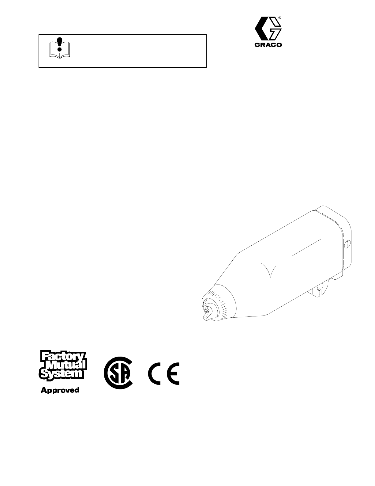
Model PRO 5500hcAir Spray Gun
100 psi (7 bar, 0.7 MPa) Maximum Working Pressure
The PRO 5500hc spray gun offers increased electrostatic performance when spraying metallic
paints and highly conductive fluids. The gun is for use with Class I, Group D paint spray
materials.
U.S. PATENT NO. 4,290,091; 4,219,865; 4,497,447; 4,462,061; 4,660,774;
5,063,350; 5,073,709; 5,080,289; 5,093,625; 5,289,977
Patented 1986, 1987 Canada
Brevete 1986, 1987
U.K. PATENT NO. 2,147,158; 2,142,559B; 2,140,327–B
Other Foreign Patents Pending
Part No. 236685, Series A
Complete PRO 5500hc Spray Gun: includes spray
gun, shroud, manifold, and mounting bracket
Part No. 237300
PRO 5500hc Conversion Kit: to convert the PRO
5500sc spray gun to the PRO 5500hc spray gun
03209
NOTE: Any modification of genuine Graco parts or replacement of parts with non-Graco parts will void agency approvals.
GRACO INC. P.O. BOX 1441 MINNEAPOLIS, MN 55440–1441
COPYRIGHT 1994, GRACO INC.
Graco Inc. is registered to I.S. EN ISO 9001
Page 2
Table of Contents
Symbols 2. . . . . . . . . . . . . . . . . . . . . . . . . . . . . . . . . . . . . .
Warnings 3. . . . . . . . . . . . . . . . . . . . . . . . . . . . . . . . . . . . .
Introduction 5. . . . . . . . . . . . . . . . . . . . . . . . . . . . . . . . . .
Comparison of a PRO 5500sc to a PRO 5500hc
Spray Gun 5. . . . . . . . . . . . . . . . . . . . . . . . . . . . . . . . .
Fluid Characteristics and Gun Performance 6. . . . . . . .
Operating the Spray Function 6. . . . . . . . . . . . . . . . . . . .
Operating the Electrostatics 6. . . . . . . . . . . . . . . . . . . . . .
Switching to the Higher or Lower kV Setting 6. . . . . . . .
Gun Features and Options 6. . . . . . . . . . . . . . . . . . . . . . .
Installation 8. . . . . . . . . . . . . . . . . . . . . . . . . . . . . . . . . . .
Installing the System 9. . . . . . . . . . . . . . . . . . . . . . . . . . . .
Warning Signs 9. . . . . . . . . . . . . . . . . . . . . . . . . . . . . . . . .
Ventilate the Spray Booth 9. . . . . . . . . . . . . . . . . . . . . . . .
Install the Air Line Accessories 10. . . . . . . . . . . . . . . . . .
Install the Fluid Line Accessories 10. . . . . . . . . . . . . . . .
Install the Gun and Mounting Bracket 10. . . . . . . . . . . .
Connect the Air and Fluid Lines 11. . . . . . . . . . . . . . . . .
Optional Fiber Optic Cable Connection 12. . . . . . . . . . .
Optional Fiber Optic Lens Kit Installation 12. . . . . . . . .
Ground the System 13. . . . . . . . . . . . . . . . . . . . . . . . . . . .
Check the Electrical Grounding 14. . . . . . . . . . . . . . . . . .
Install the Fabric Cover 15. . . . . . . . . . . . . . . . . . . . . . . . .
Service 28. . . . . . . . . . . . . . . . . . . . . . . . . . . . . . . . . . . . . .
Tools Included with the Gun 28. . . . . . . . . . . . . . . . . . . . .
Prepare the Gun for Service 28. . . . . . . . . . . . . . . . . . . .
Air Cap/Nozzle/Resistor Stud Replacement 29. . . . . . .
Electrode Needle Replacement 30. . . . . . . . . . . . . . . . . .
Fluid Packing Rod Removal and Repair 31. . . . . . . . . .
Piston Repair 32. . . . . . . . . . . . . . . . . . . . . . . . . . . . . . . . .
Barrel Removal 34. . . . . . . . . . . . . . . . . . . . . . . . . . . . . . .
Power Supply Removal and Replacement 35. . . . . . . .
Power Supply Adjustment 35. . . . . . . . . . . . . . . . . . . . . .
Turbine Alternator Removal and Replacement 36. . . . .
Barrel Installation 36. . . . . . . . . . . . . . . . . . . . . . . . . . . . . .
Install the Gun onto the Manifold 37. . . . . . . . . . . . . . . .
Standard Spray Gun Parts 38. . . . . . . . . . . . . . . . . . . .
Manifold Parts 40. . . . . . . . . . . . . . . . . . . . . . . . . . . . . . .
Kit Parts and Installation 42. . . . . . . . . . . . . . . . . . . . .
Installing the PRO 5500hc Conversion Kit 42. . . . . . . .
Technical Data 43. . . . . . . . . . . . . . . . . . . . . . . . . . . . . . .
Accessories 44. . . . . . . . . . . . . . . . . . . . . . . . . . . . . . . . .
The Graco Warranty and Disclaimers 46. . . . . . . . . .
Operation 16. . . . . . . . . . . . . . . . . . . . . . . . . . . . . . . . . . . .
Pressure Relief Procedure 16. . . . . . . . . . . . . . . . . . . . . .
Operating Checklist 16. . . . . . . . . . . . . . . . . . . . . . . . . . . .
Selecting a Fluid Nozzle and Air Cap 16. . . . . . . . . . . . .
Adjusting the Spray Pattern 17. . . . . . . . . . . . . . . . . . . . .
Activating and Adjusting the Electrostatics 18. . . . . . . .
Activating the kV Switch 18. . . . . . . . . . . . . . . . . . . . . . . .
Spraying 18. . . . . . . . . . . . . . . . . . . . . . . . . . . . . . . . . . . . .
Triggering the Fluid Alone 18. . . . . . . . . . . . . . . . . . . . . .
Shutdown 19. . . . . . . . . . . . . . . . . . . . . . . . . . . . . . . . . . . .
Maintenance 19. . . . . . . . . . . . . . . . . . . . . . . . . . . . . . . . .
Daily Care and Cleaning 19. . . . . . . . . . . . . . . . . . . . . . . .
Clean the Air Cap and Fluid Nozzle 21. . . . . . . . . . . . . .
Check for Fluid Leakage 22. . . . . . . . . . . . . . . . . . . . . . .
Troubleshooting 23. . . . . . . . . . . . . . . . . . . . . . . . . . . . .
Spray Pattern Troubleshooting 23. . . . . . . . . . . . . . . . . .
Gun Operation Troubleshooting 24. . . . . . . . . . . . . . . . .
Electrical Troubleshooting 25. . . . . . . . . . . . . . . . . . . . . .
Electrical Tests 26. . . . . . . . . . . . . . . . . . . . . . . . . . . . . . .
Test Gun Resistance 26. . . . . . . . . . . . . . . . . . . . . . . . . . .
Test Power Supply Resistance 27. . . . . . . . . . . . . . . . . .
Test Resistor Stud Resistance 27. . . . . . . . . . . . . . . . . .
Graco Phone Number 46. . . . . . . . . . . . . . . . . . . . . . . .
Symbols
Warning Symbol
WARNING
This symbol alerts you to the possibility of serious
injury or death if you do not follow the instructions.
Caution Symbol
CAUTION
This symbol alerts you to the possibility of damage to
or destruction of equipment if you do not follow the
corresponding instructions.
2 308442
Page 3
WARNING
FIRE, EXPLOSION, AND ELECTRIC SHOCK HAZARD
Improper grounding, poor air ventilation, open flames, or sparks can cause a hazardous condition and
result in a fire, explosion, or electric shock.
Electrostatic equipment must be used only by trained, qualified personnel who understand the
requirements stated in this instruction manual.
Ground the equipment, personnel in or close to the spray area, the object being sprayed, and all
other electrically conductive objects in the spray area. See Ground the System on page 13.
Check the spray gun resistance daily. See Test Gun Resistance, page 26.
If there is any static sparking while using the equipment, stop spraying immediately. Identify and
correct the problem.
Provide fresh air ventilation to avoid the buildup of flammable or toxic vapors. Interlock the gun
turbine air supply to prevent operation of the power supply unless the ventilating fans are on. See
Ventilate the Spray Booth on page 9.
When flushing or purging electrostatic equipment, use solvents with a flash point equal to or
greater than that of the fluid being sprayed.
To clean the exterior of the electrostatic equipment, use solvents with a flash point higher than
100F (38C).
Do not flush the system with the gun electrostatics turned on.
Do not turn on the gun electrostatics until all solvent is removed from the system.
Use only non-sparking tools to clean residue from the booth and hangers.
Extinguish all open flames or pilot lights in the spray area.
Keep the spray area free of debris, including solvent, rags, and gasoline.
Do not store any flammable fluids in the spray area.
Do not turn on or off any light switch in the spray area while operating or if fumes are present.
Do not smoke in the spray area.
Do not operate a gasoline engine in the spray area.
PRESSURIZED EQUIPMENT HAZARD
Spray from the gun, hose leaks, or ruptured components can splash fluid in the eyes or on the skin
and cause a serious injury.
Do not point the spray gun at anyone or any part of the body.
Do not stop or deflect fluid leaks with your hand, body, glove, or rag.
Follow the Pressure Relief Procedure on page 16 whenever you: are instructed to relieve the
pressure; stop spraying; clean, check, or servicing the equipment; and install or clean the fluid
nozzles.
Tighten all the fluid connections before operating the equipment.
Check the hoses, tubes and couplings daily. Replace worn, damaged, or loose parts immediately.
Permanently coupled hoses cannot be repaired; replace the entire hose.
Warnings are continued on the next page.
308442 3
Page 4
INSTRUCTIONS
WARNING
EQUIPMENT MISUSE HAZARD
Equipment misuse can cause the equipment to rupture, malfunction, or start unexpectedly and result
in a serious injury.
This equipment is for professional use only.
Read all the instruction manuals, tags, and labels before operating the equipment.
Use the equipment only for its intended purpose. If you are uncertain about the usage, call your
Graco distributor.
Do not alter or modify this equipment. Use only genuine Graco parts and accessories.
Check the equipment daily. Repair or replace worn or damaged parts immediately.
Do not exceed the maximum working pressure of the lowest rated system component. This equip-
ment has a 100 psi (7 bar, 0.7 MPa) maximum working air and fluid pressure.
Use fluids that are compatible with the equipment wetted parts. See the Technical Data section of
all the equipment manuals. Read the fluid manufacturer’s warnings.
Route the hoses away from traffic areas, sharp edges, moving parts, and hot surfaces. Do not
expose Graco hoses to temperatures above 180F (82C) or below –40F (–40C).
Do not use the hoses to pull equipment.
Wear hearing protection when operating this equipment.
Comply with all applicable local, state, and national fire, electrical, and other safety regulations.
TOXIC FLUID HAZARD
Hazardous fluids or toxic fumes can cause a serious injury or death if splashed in the eyes or on the
skin, swallowed, or inhaled.
Know the specific hazards of the fluid you are using. Read the fluid manufacturer’s warnings.
Store hazardous fluid in an approved container. Dispose of the hazardous fluid according to all
local, state, and national guidelines.
Wear appropriate protective clothing, gloves, eyewear, and respirator.
4 308442
Page 5
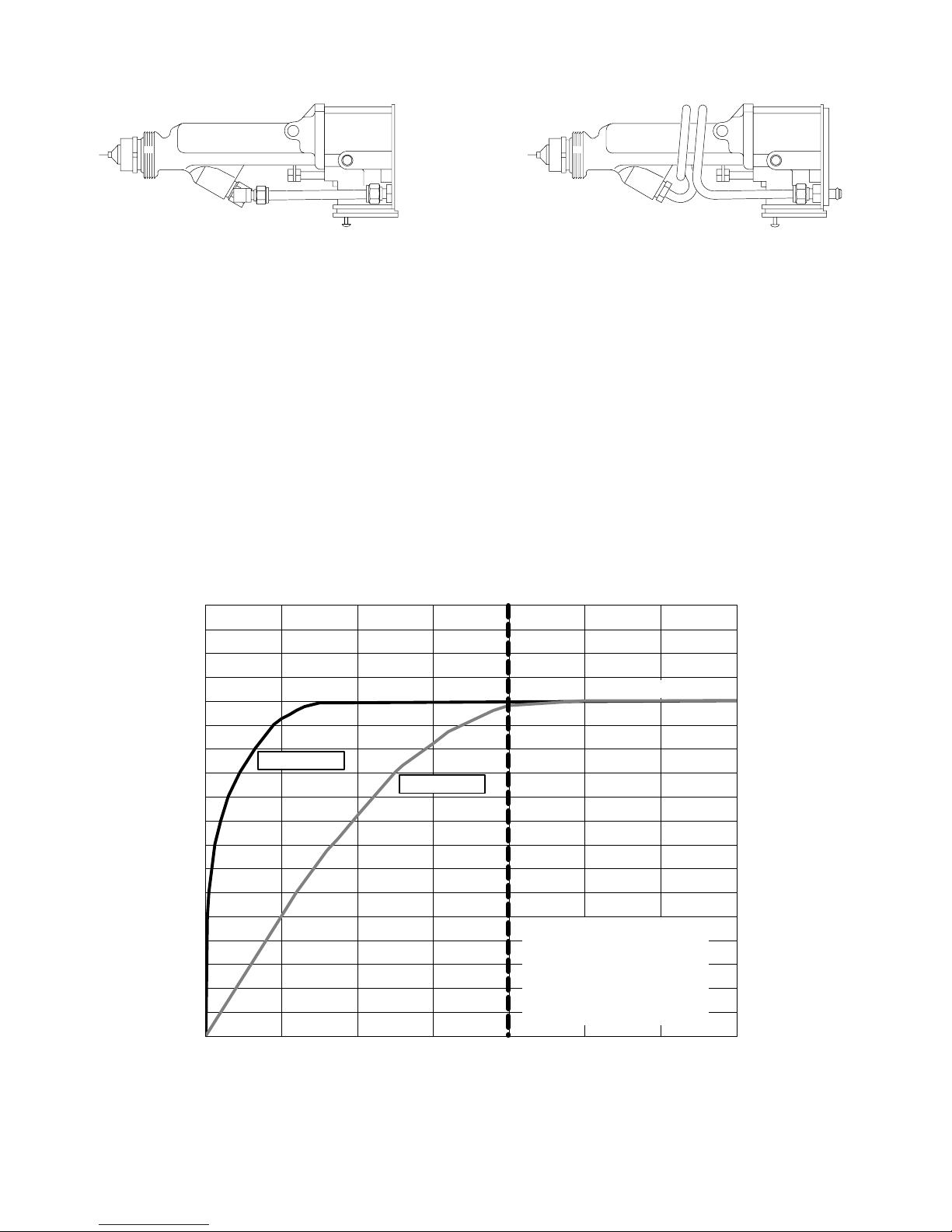
Introduction
03221 03904A
PRO 5500sc Spray Gun
8 in. (203.2 mm) fluid path
Comparison of a PRO 5500sc to a PRO
5500hc Spray Gun
The PRO 5500hc spray gun offers increased electrostatic performance when spraying highly conductive
fluids and metallic paints.
In an electrostatic spray gun, the fluid in the fluid tube
becomes a path to ground when the high voltage is
turned on. The amount of current drawn through the
fluid tube depends on the fluid resistivity and the length
of the fluid path to ground.
PRO 5500hc Spray Gun
20 in. (711.2 mm) fluid path
The PRO 5500sc and PRO 5500hc guns will perform
equally well when spraying fluids with high resistivity,
as shown in the graph below. Even with the shorter
fluid tube of the PRO 5500sc gun, very little current
travels through the fluid, due to its high resistivity, and
the spraying voltage is minimally affected. However,
when the fluid resistivity decreases to low levels, more
current is drawn through the fluid and the spraying
voltage of the PRO 5500sc gun is reduced.
The PRO 5500hc gun can support high voltages when
spraying conductive fluids because the longer fluid
tube increases the total resistance of the fluid column
and reduces the current draw through the fluid.
Full Spraying Voltage
kV
Low Resistivity
(high conductivity)
PRO 5500hc
PRO 5500sc
NOTE: Fluid resistance
value is approximate.
Actual resistance will
vary depending on the
type of resistance meter
and the fluid being used.
200
High Resistivity
(low conductivity)
Fluid Resistivity MEG CM
308442 5
Page 6

Introduction
Fluid Characteristics and Gun Performance
For some fluids (especially metallic paints), measuring
the fluid resistivity is not always a reliable indicator of
paint performance in a spray gun. The voltage applied
by the resistivity meter is very low compared to the
voltage applied by the spray gun. Some conductive
components and additives in the fluid may exhibit
reduced resistivity when high voltage is applied by the
spray gun.
When testing a fluid to see if it will be suitable for
electrostatic spraying, it is important to measure the
spraying voltage when the fluid is flowing. The turbulence created when the fluid is flowing helps to retard
the negative effects of the conductive components and
additives in the fluid.
The PRO 5500hc guns offer the capability of monitoring the actual spraying voltage with the optional fiber
optic spraying voltage readouts. Either the kV only
readout or the kV and current readout can be very
helpful in monitoring the voltage characteristics when
spraying conductive fluids. Refer to Fig. 2, page 8.
To provide a smoother transition to the high voltage
and prevent some very conductive fluids from shorting
out, it may be necessary to operate the gun with the
voltage first turned to the lower kV setting, then switch
to the higher kV setting.
Operating the Spray Function
Applying a minimum of 50 psi (3.5 bar, 0.35 MPa) air
pressure to the gun manifold’s cylinder air fitting (which
is marked “CYL”, see page 7) will retract the gun
piston, which opens the air valves and a short time
later opens the fluid needle. This provides the proper
air lead and lag when triggering the gun. A spring
returns the piston when the cylinder air is shut off.
Operating the Electrostatics
To operate the electrostatics, air pressure is applied to
the gun manifold’s turbine air fitting (which is marked
“TA”, see page 7) through a Graco electrically conductive air hose. The air enters the manifold and is
directed to the inlet of the power supply turbine (G).
The air spins the turbine, which then provides electrical
power to the internal high voltage power supply (H).
The fluid is charged by the spray gun electrode (J).
The charged fluid is attracted to the nearest grounded
object, wrapping around and evenly coating all surfaces.
The turbine air is exhausted into the shroud (D) and
out the back of the manifold through the fitting marked
“EXH”. The exhaust air helps keep contaminants out
and helps keep the gun clean.
Switching to the Higher or Lower
kV Setting
The gun’s full high voltage setting is 85 kilovolts. The
gun’s spraying voltage can be reduced by switching to
the low voltage setting for spraying in areas where too
much electrostatic wrap is not desirable. Applying a
minimum of 50 psi (3.5 bar, 0.35 MPa) air pressure to
the kV switch air inlet (which is marked “KV”, see page
7) will activate it and switch to the lower voltage setting. The lower voltage is factory set to 60 kilovolts at
zero microamperes. This setting can be adjusted from
45 to 80 kilovolts, as instructed on page 35. The solenoid valve used to activate the kV switch must bleed
the air out of the line for the switch to draw back to the
higher voltage setting.
Gun Features and Options
The gun is designed for use with a reciprocator,
and it can be directly mounted to a one-half inch
rod. With additional brackets, the gun can be
mounted for robotic applications.
The gun is designed for quick-disconnect, which
enables the operator to quickly remove the spray
gun without disconnecting the fluid and air lines to
the gun.
The gun functions are activated from a separate
controller that sends the appropriate signal to the
actuating solenoids (K). See Fig. 1, page 8.
An optional fiber optic readout system can be
installed to monitor the gun’s spraying voltage. A
fiber optic cable (V) connected to the gun manifold
carries the signal from the gun to a remote ES
(electrostatic) display module. See Fig. 2, page 8.
An ES Display Module (R), P/N 224117, is available
and will display the gun’s spraying voltage and
current. A battery operated ES Display Module (S),
P/N 189762, is also available; it displays the gun’s
spraying voltage only.
6 308442
Page 7
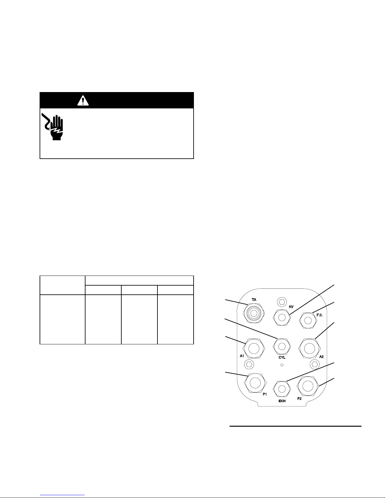
Introduction
F
AB C D E
TA
CYL
A1
P1
KV
F.O.
A2
EXH
P2
Manifold Back View
0321303209
KEY
A Air Cap
B Fluid Nozzle
C Retaining Nut
D Shroud
E Mounting Bracket
F Manifold
G Turbine
H Power Supply
J Electrode
H
J
G
04803
Manifold Markings
A1 Atomization Air Inlet Fitting
A2 Fan Air Inlet Fitting
CYL Cylinder Air Inlet Fitting
EXH Shroud Exhaust Outlet Fitting
F.O. Fiber Optic Fitting
KV kV Switch Air Inlet
P1 Fluid Supply Inlet Fitting
P2 Fluid Return Inlet Fitting
TA Turbine Air Inlet Fitting
308442 7
Page 8
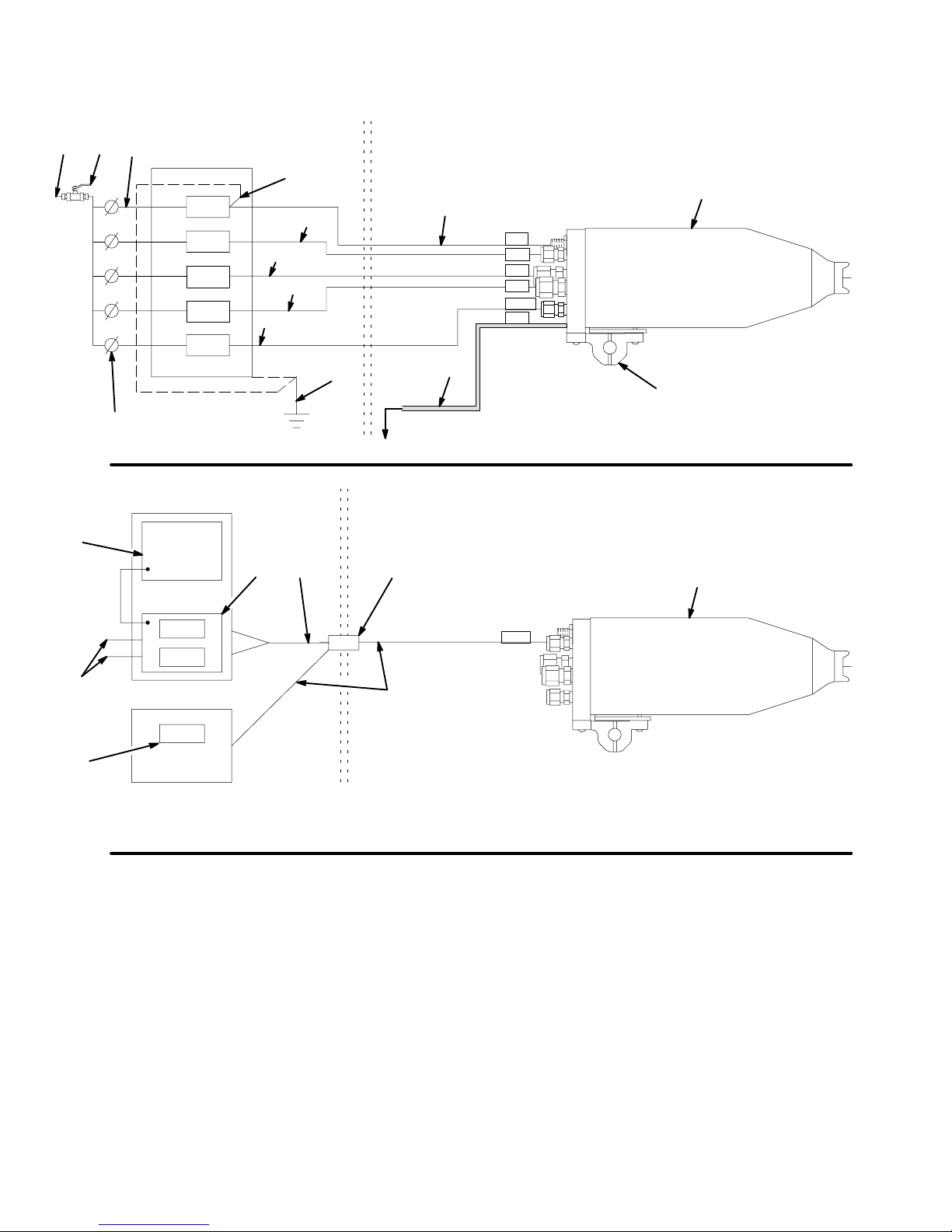
Fig. 1
Installation
BASIC SYSTEM
Non-Hazardous Area Hazardous Area
XW
A
H
B
TA
*
KV
*
A1
*
A2
*
CYL
*
P1
*
F
J
M
K
K
K
K
Y
C
D
E
K
N
G
P
Q
S
Fig. 2
Non-Hazardous Area Hazardous Area
RT
kV
mA
kV
U
*
V
SYSTEM OPTIONS
Spraying Voltage
Display Module
H
F.O.
04801
8 308442
Page 9

Installation
KEY-Fig. 1 and 2
A Ground Wire on Graco Electrically Conductive Air Hose
B Graco Electrically Conductive Air Hose (Turbine Air Hose),
See page 11 for part numbers
C Atomizing Air Hose, 3/8 inch (9.5 mm) O.D.
D Fan Air Hose, 3/8 inch (9.5 mm) O.D.
E Cylinder Air Hose, 1/4 inch (6.4 mm) O.D.
F Fluid Hose, 1/4–18.6 npsm gun fluid inlet
G To Fluid Supply
H PRO 5500hc Spray Gun, P/N 236685
J Mounting Bracket for 1/2 inch (127 mm) rod, P/N 189581
K Solenoid Valve, requires quick-exhaust port
M Air Pressure Regulator
N True Earth Ground
P 24 Volt Power Supply, P/N 235301
Q4–20 mA Outputs
R Full Feature ES Display Module, P/N 224117
S kV Only ES Display Module (battery operated), P/N 189762
T Fiber Optic Cable, P/N 224680 to 224686
U Bulkhead, P/N 189870
V Fiber Optic Cable, P/N 224670 to 224676
W Main Air Line
X Bleed-type Master Air Valve
Y kV Switch Air Hose, 1/4 inch (6.4 mm) O.D., plug the gun fitting if
it is not used
Z Air Pilot Fluid Regulator, P/N 236854
The turbine air supply must be interlocked with the spray booth
ventilation fans.
A maximum of two splices with a total of 108 feet (32.94 m) of
cable can be used. For the strongest light signals, use a minimum
number of bulkhead splices.
* See page 11 for a description of the manifold connections.
Installing the System
Fig. 1, page 8, shows a typical Model PRO 5500hc
system. Fig. 2 shows some possible system options.
Accessories are available from your Graco representative. Refer to the Product Data Sheet for the gun,
Form No. 305660.
For assistance in designing a system that is customized for your application, contact your Graco distributor.
Warning Signs
Mount the warning signs in the spray area where they
can easily be seen and read by all operators. An
English Warning Sign is provided with the gun. Additional signs are available at no charge. See below.
Part No. Description
180060 Warning Sign (English)
Ventilate the Spray Booth
WARNING
FIRE, EXPLOSION, AND
ELECTRIC SHOCK HAZARD
Installing and servicing this equipment
requires access to parts which may
cause electric shock or other serious
injury if work is not performed properly.
Do not install or service this equip-
ment unless you are trained and
qualified.
Be sure your installation complies with National,
State and Local codes for the installation of
electrical apparatus in a Class I, Group D
Hazardous Location.
Comply with all applicable local, state, and
national fire, electrical, and other safety regulations.
WARNING
FLAMMABLE OR TOXIC
VAPOR HAZARD
Provide fresh air ventilation to avoid the
buildup of flammable or toxic vapors. Do
not operate the gun unless ventilation
fans are operating.
Electrically interlock the gun turbine air supply line with
the ventilators to prevent operation of the electrostatic
power supply unless ventilating fans are on.
Check and follow all local, state, and national codes
regarding air exhaust velocity requirements. High
velocity air exhaust will decrease the operating efficiency of the electrostatic system. The minimum
allowable air exhaust velocity is 60 feet/minute (19
linear meters/minute).
308442 9
Page 10
Installation
Install the Air Line Accessories
1. Install a bleed-type master air valve (X) on the
main air supply line (W) to shut off all the air to the
gun. See Fig. 1, page 8.
2. To ensure a dry, clean air supply to the gun, install
an air line filter and an air and water separator on
the air lines. Dirt and moisture can ruin the appearance of your finished workpiece and can cause the
gun to malfunction.
3. Install an air regulator (M) on each of the air supply
lines (B, C, D, E, Y) to control the air pressure to
the gun.
4. Install a solenoid valve (K) on the fan and atomization air lines (C, D) to actuate the gun and shut off
the fan and atomization air to the gun. The solenoid valves must have a quick exhaust port.
WARNING
PRESSURIZED EQUIPMENT HAZARD
Trapped air can cause the gun to spray
unexpectedly, which could result in a
serious injury, including splashing in the
eyes or on the skin. The solenoid valves (K) must
have a quick-exhaust port so trapped air will be
relieved between the valve and the gun when the
solenoids are shut off.
Install the Fluid Line Accessories
1. Install a fluid filter and drain valve at the pump
outlet. See Fig. 1, page 8.
WARNING
2. Install a fluid regulator on the fluid line to control
fluid pressure to the gun.
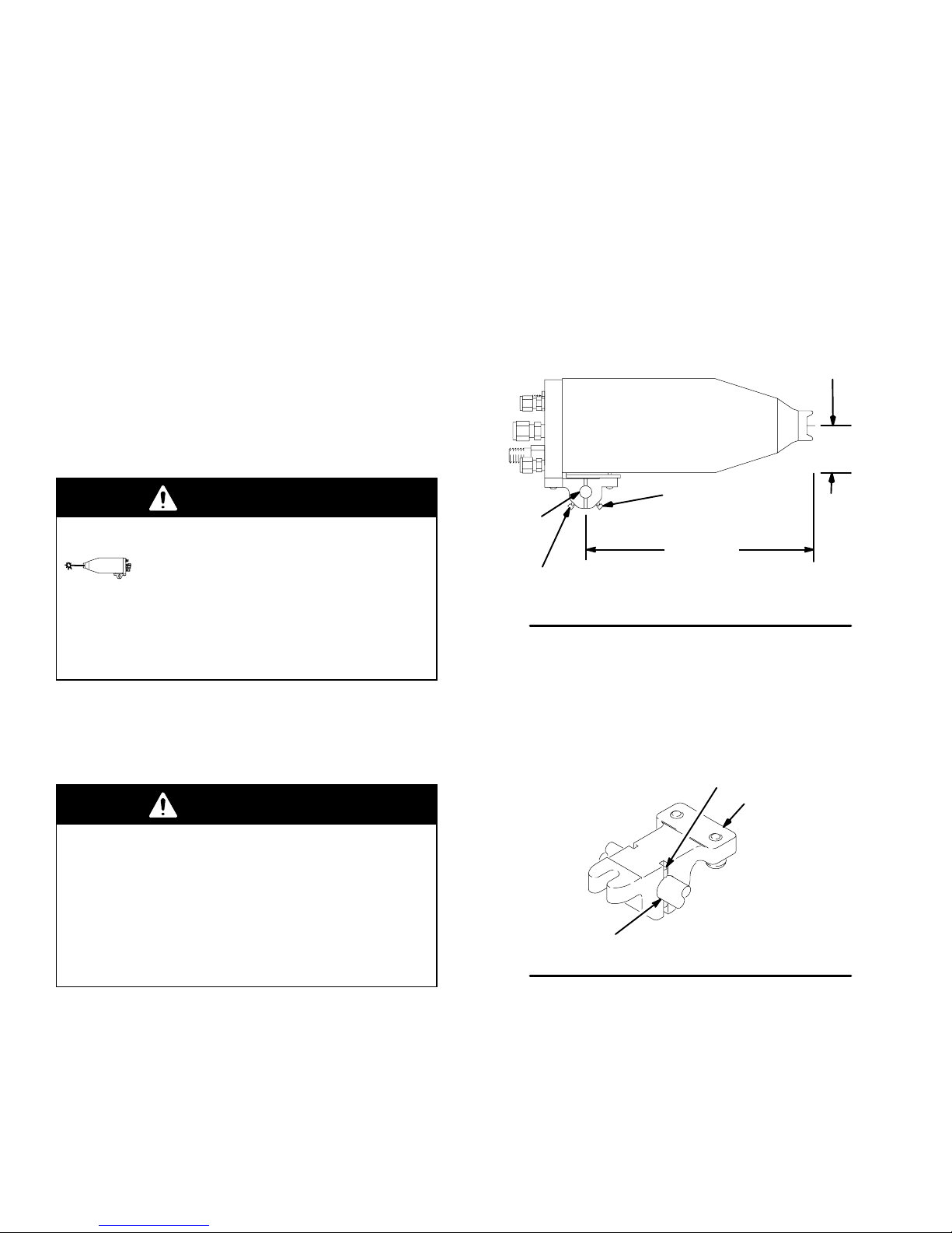
Install the Gun and Mounting Bracket
1. Loosen the mounting bracket’s two square head
bolts (103) and slide the mounting bracket onto a
0.50 in. (12.7 mm) mounting rod. See Fig. 3.
2. Position the gun and tighten the two bolts (103)
securely.
2.775 in .
(70.5 mm)
PRO 5500 Gun
103
0.50 in.
(12.7 mm)
rod
103
Fig. 3
NOTE: For added positioning reliability, the mounting
bracket (MM) has an 1/8 in. (3.2 mm) slot where a
locating pin (NN-not included) can be inserted through
the mounting rod (PP). See Fig. 4.
9.32 in.
(236.7 mm)
03444
NN
MM
PRESSURIZED EQUIPMENT HAZARD
The fluid drain valve is required in your system to
assist in relieving fluid pressure in the displacement
pump, hose and gun; triggering the gun to relieve
pressure may not be sufficient. Install a drain valve
close to the pump’s fluid outlet. The drain valve
reduces the risk of serious injury, including splashing in the eyes or on the skin.
10 308442
Fig. 4
PP
03460
Page 11
Installation
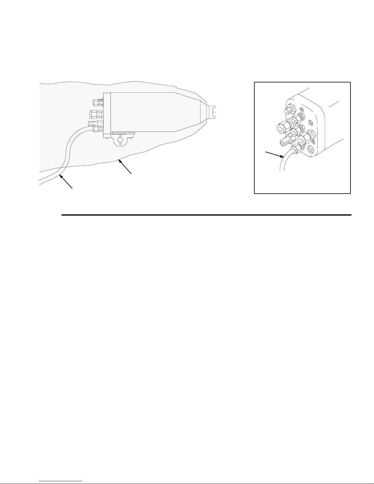
Connect the Air and Fluid Lines
See Fig. 1 and 2, page 8, for a schematic of air and
fluid connections. Connect the air and fluid lines to the
gun manifold as instructed at right.
Graco Electrically Conductive Air Hose
WARNING
ELECTRIC SHOCK HAZARD
To reduce the risk of electric shock or
other serious injury, the air supply hose
must be electrically connected to a true
earth ground. Use Only Graco Electrically Con-
ductive Air Supply Hose.
Connect the Graco electrically conductive air hose (B)
to the gun turbine air inlet and connect the hose
ground wire (A) to a true earth ground. See Fig. 1,
page 8. Check the electrical grounding of the gun as
instructed on page 14.
NOTE: The hose and the gun have special left-hand
threads to prevent connecting another type of air hose
to the gun turbine air inlet.
Graco Electrically Conductive Air Hose
Required for gun operation.
100 psi (7 bar, 0.7 MPa) Maximum Working Pressure
0.315 in. (8 mm) ID; 1/4 npsm(f) x 1/4 npsm(f) left-hand
Manifold Connections (See Fig. 5)
A1 Atomization Air Inlet Fitting
Connect a 3/8 inch O.D. tube between the fitting and
the air supply.
A2 Fan Air Inlet Fitting
Connect a 3/8 inch O.D. tube between the fitting and
the air supply.
CYL Cylinder Air Inlet Fitting
Connect a 1/4 inch O.D. tube between this fitting and
the solenoid. For quicker trigger response, use the
shortest hose length possible.
EXH Shroud Exhaust Outlet Fitting
Connect a 1/4 inch O.D. x 4 foot (1.22 m) long tube to
the fitting.
F.O. Fiber Optic Fitting (Optional)
Connect the Graco Fiber Optic Cable as instructed on
page 12.
KV kV Switch Air Inlet Fitting
Connect a 1/4 inch O.D. tube between the fitting and
the air solenoid.
P1 Fluid Supply Inlet Fitting
Connect a 1/4 inch npsm swivel fitting between the
fitting and the fluid supply.
P2 Fluid Return Inlet Fitting (Optional)
Connect 1/4 inch O.D. tube between the fitting and the
dump valve for recirculation.
TA Turbine Air Inlet Fitting
Connect the Graco Electrically Conductive Air Hose
between this fitting (left-hand thread) and the solenoid.
Connect the air hose ground wire to a true earth
ground.
Part No.
Length Black Hose Grey Hose Red Hose
6 ft. (1.8 m)
15 ft. (4.6 m)
25 ft. (7.6 m)
36 ft. (11.0 m)
50 ft. (15.2 m)
75 ft. (23.0 m)
100 ft. (30. 5 m)
Black Hose: standard hose, semi-conductive nylon core,
urethane outer
Grey Hose: more flexible (less durable) than black hose,
modified semi-conductive polyamide core, urethane cover
Red Hose: conductive SST wire braid for grounding, polyurethane tube and cover
220444
218100
218101
218102
218103
220119
220120
223068
223069
223070
223071
223072
223073
223074
235068
235069
235070
235071
235072
235073
235074
Fluid Line
Before connecting the fluid line, blow it out with air and
flush it with solvent. Use solvent that is compatible with
the fluid being sprayed.
TA
CYL
A1
P1
Fig. 5
KV
F.O.
A2
EXH
P2
Manifold Back View
03213
308442 11
Page 12
Installation
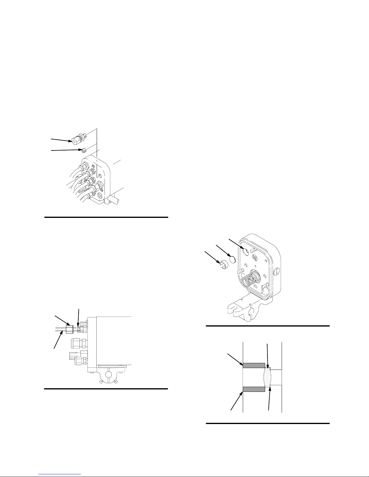
Optional Fiber Optic Cable Connection
An optional fiber optic fitting (37) is shipped unassembled with the gun. If an ES (kV) display module is
used, install the fitting in the manifold. See Fig. 2, page
8, for a schematic of the fiber optic connections.
1. Remove the 1/8 npt plug (115) from the manifold’s
fiber optic port, and install the black fiber optic
fitting (37). See Fig. 6.
37
115
Fig. 6
03508
NOTE: Most of the fiber optic light transmission loss
occurs at the bulkhead splices. For the strongest light
signals, use a minimum number of bulkhead splices. A
maximum of two splices, with a total of 108 feet (32.94
m) of cable, is recommended.
5. See manual 308265 to install a Graco ES Display
Module.
Optional Fiber Optic Lens Kit Installation
NOTE: The fiber optic lens kit is not included with the
gun. Order it separately; the part number is 236852.
1. Remove the gun from the manifold as instructed
on page 28.
2. Make sure the lens (TT) is clean. Push the lens
into the counterbore (VV) in the manifold fiber optic
port (SS). See Fig. 8 and 9.
3. Press the lens retainer (UU) into the manifold fiber
optic port (SS) until it is flush with the manifold
surface.
4. Assemble the gun to the manifold as instructed on
page 37.
2. Remove the nut (QQ) from the fiber optic fitting
(37), and slide the nut over the end of the fiber
optic cable (RR). See Fig. 7.
3. Insert the cable (RR) into the fitting (37), and push
the cable in until it bottoms out. Tighten the nut
(QQ) to secure the cable.
37
QQ
RR
Fig. 7
4. If you have two bulkhead splices in your system, it
is recommended that you install the fiber optic lens
kit, as described at right.
03509A
UU
Fig. 8
Fig. 9
TT
SS
UU
TT
VVSS
04798
04485
12 308442
Page 13
Installation
Ground the System
WARNING
FIRE, EXPLOSION, AND
ELECTRIC SHOCK HAZARD
When operating the electrostatic gun,
any ungrounded objects in the spray
area (such as people, containers, tools,
etc.) can become electrically charged.
Improper grounding can result in static
sparking, which can cause a fire, explosion, or electric shock. Follow the
grounding instructions below.
The following grounding instructions are minimum
requirements for a basic electrostatic system. Your
system may include other equipment or objects which
must be grounded. Check your local electrical code for
detailed grounding instructions. Your system must be
connected to a true earth ground.
1. Pump: ground the pump by connecting a ground
wire and clamp as described in your separate
pump instruction manual.
3. Electrostatic Air Spray Gun: ground the gun by
connecting the Graco Electrically Conductive Air
Hose to the turbine air inlet and connecting the air
hose ground wire to a true earth ground. Check
the electrical grounding of the gun as instructed on
page 14.
4. All air and fluid lines must be properly grounded.
5. All electric cables must be properly grounded.
6. All persons entering the spray area: their shoes
must have conductive soles, such as leather, or
personal grounding straps must be worn. Rubber
or plastic soles are not conductive.
7. Object being sprayed: keep the workpiece hangers
clean and grounded at all times. Contact points
must be sharp points or knife edges.
8. The floor of the spray area: must be electrically
conductive and grounded. Do not cover the floor
with cardboard or any non-conductive material
which would interrupt grounding continuity.
9. Flammable liquids in the spray area: must be kept
in approved, grounded containers. Do not store
more than the quantity needed for one shift.
2. Air compressors and hydraulic power supplies:
ground the equipment according to the manufacturer’s recommendations.
10. All electrically conductive objects or devices in the
spray area: including fluid containers and wash
cans, must be properly grounded.
308442 13
Page 14
Installation
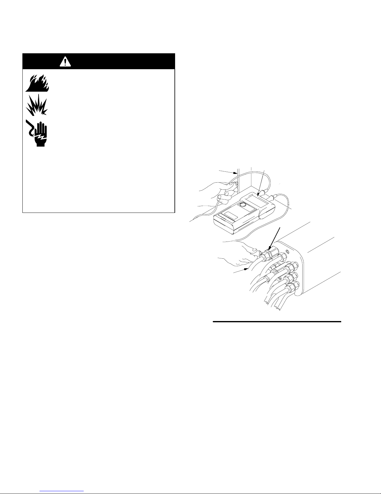
Check the Electrical Grounding (See Fig. 10)
WARNING
FIRE, EXPLOSION, AND
ELECTRIC SHOCK HAZARD
Megohmmeter P/N 241079 (WW) is not
approved for use in a hazardous area.
To reduce the risk of sparking, do not
use the megohmmeter to check electrical grounding unless:
The gun has been removed from the
hazardous area;
Or all spraying devices in the hazardous area
are turned off, ventilation fans in the hazardous
area are operating, and there are no flammable
vapors in the area (such as open solvent containers or fumes from spraying).
Failure to follow this warning could cause fire,
explosion, electric shock and result in serious injury
and property damage.
a. If using a black or grey turbine air hose, use a
megohmmeter (WW) to measure the
resistance. Use an applied voltage of 500
minimum to 1000 volts maximum. Resistance
should not exceed 2 megohms.
b. If you are using a red turbine air hose, use an
ohmmeter to measure the resistance.
Resistance should not exceed 100 ohms.
5. If the resistance is greater than the maximum
reading specified above for your hose, check the
tightness of the ground connections and be sure
the turbine air hose ground wire is connected to a
true earth ground. If the resistance is still too high,
replace the turbine air hose.
N
WW
1. Have a qualified electrician check the electrical
grounding continuity of the spray gun and turbine
air hose.
2. Make sure the turbine air hose (B) is connected
and the hose ground wire is connected to a true
earth ground.
3. The air and fluid supplies to the gun must be
turned off, and the fluid hose must not have any
fluid in it when checking the continuity.
4. Measure the resistance between the turbine air
inlet fitting (TA) and a true earth ground (N).
TA
B
TI0376
Fig. 10
14 308442
Page 15
Installation
Install the Fabric Cover (See Fig. 11)
1. Install the fabric cover (XX) over the front of the
gun and slide it back to cover the exposed tubing
and hoses at the back of the manifold.
XX
YY
Fig. 11
2. Route the exhaust tube (YY) outside the cover.
This enables you to monitor the exhaust tube for
the presence of any paint or solvent. See Check
for Fluid Leakage on page 22. Strap down the
exhaust tube to prevent it from moving around.
YY
Manifold Back View
03446
03445
308442 15
Page 16

Operation
Pressure Relief Procedure
WARNING
PRESSURIZED EQUIPMENT HAZARD
The system pressure must be manually
relieved to prevent the system from
starting or spraying accidentally. To
reduce the risk of an injury from accidental spray
from the gun, splashing fluid, or moving parts,
follow the Pressure Relief Procedure whenever
you:
are instructed to relieve the pressure,
stop spraying,
check or service any of the system equipment,
and install or clean the fluid nozzle.
1. Turn off all the air to the spray gun except the
cylinder air, which triggers the gun. If an air pilot
fluid regulator is used in the system, the air pressure is needed at the regulator air inlet.
2. Turn off the fluid supply to the gun.
3. Trigger the gun into a grounded metal waste
container to relieve fluid pressure.
4. If the air pilot fluid regulator is used, turn off the air
pressure at the regulator air inlet.
5. Relieve fluid pressure in the fluid supply equipment
as instructed in its instruction manual.
6. Turn off the main air supply by closing the bleedtype master air valve on the main air supply line.
Leave the valve closed until you are ready to spray
again.
Operating Checklist
Check the following list daily, before starting to operate
the system, to help ensure you of safe, efficient operation.
____ 1. All the operators are properly trained to
safely operate an automatic electrostatic air
spray system as instructed in this manual.
____ 2. All the operators are trained how to properly
relieve pressure, using the Pressure Relief
Procedure at left.
____ 3. The warning sign provided with the gun is
mounted in the spray area where it can be
easily seen and read by all operators.
____ 4. The system is thoroughly grounded and the
operator and all persons entering the spray
area are properly grounded. See Ground
the System, page 13.
____ 5. The condition of the electrical components of
the spray gun has been checked as
instructed in Electrical Tests, page 26.
____ 6. The ventilation fans are operating properly.
____ 7. The workpiece hangers are clean and
grounded. Contact points must be sharp
points or like knife edges.
____ 8. All the debris, including flammable liquids
and rags, is removed from the spray area.
____ 9. All flammable liquids in the spray booth are
in approved, grounded containers.
____ 10. All conductive objects in the spray area are
electrically grounded and the floor of the
spray area is electrically conductive and
grounded.
____ 11. The manifold exhaust tubes have been
checked for the presence of any fluid as
instructed in Check for Fluid Leakage, page
22.
Selecting a Fluid Nozzle and Air Cap
WARNING
PRESSURIZED EQUIPMENT HAZARD
To reduce the risk of an injury, follow the Pressure
Relief Procedure, above, before removing or
installing a fluid nozzle and/or air cap.
The gun is supplied with a 0.059 in. (1.5 mm)) fluid
nozzle, part no. 191833, and air cap, part no. 193033.
If your application requires a different nozzle and air
cap combination, use instruction manual 307803 or
consult your authorized Graco distributor to select the
appropriate fluid nozzle and air cap. Install the air cap
and fluid nozzle into the gun barrel as instructed in Air
Cap/Nozzle/Resistor Stud Replacement, page 29.
16 308442
Page 17

Operation
Adjusting the Spray Pattern
Follow the steps below to establish the correct fluid
flow and air flow. Do not turn on the turbine air (TA)
yet.
WARNING
PRESSURIZED EQUIPMENT HAZARD
To reduce the risk of a serious injury,
follow the Pressure Relief Procedure
on page 16 whenever you are instructed
to relieve the pressure.
1. Make sure the system pressure is relieved.
2. Loosen the air cap retaining ring, and rotate the air
cap for a vertical or horizontal spray pattern. See
Fig. 12. Then tighten the retaining ring until the air
cap is held firmly in place; you should not be able
to rotate the air cap horns by hand.
4. Use the air pressure regulator on the atomization
air supply line (A1) to adjust the degree of atomization. Refer to Fig. 13. For example, for a fluid
flow rate of 10 ounces per minute (0.3 liters/min.),
a typical atomization pressure would be 20 to 30
psi (1.4–2.1 bar, 0.14–0.21 MPa) at the gun manifold.
5. Use the air pressure regulator on the fan air supply
line (A2) to adjust the pattern size.
NOTES:
For the most efficiency, always use the lowest air
pressure possible.
When increasing to a wide, flat pattern, it may be
necessary to increase the supply of fluid to the gun
to maintain the same amount of coverage over a
large area.
See Spray Pattern Troubleshooting on page 23
to correct spray pattern problems.
KV
TA
Vertical Pattern
Horizontal Pattern
Fig. 12
3. Adjust the fluid flow with the fluid line pressure
regulator. Refer to instruction manual 307803 to
set the fluid pressure for various fluid flows,
according to the size of the fluid nozzle being
used.
02020
CYL
A1
Fig. 13
Manifold Back View
A2
03213
308442 17
Page 18

Operation
Activating and Adjusting the
Electrostatics
1. Make sure the fan (A2) and atomizing (A1) air are
on, then turn on the turbine air (TA). Refer to Fig.
13, page 17.
2. The turbine air pressure should be adjusted to 30
psi (2.1 bar, 0.21 MPa) at the gun manifold inlet
when air is flowing. Do not exceed 40 psi (2.8 bar,
0.28 MPa) air pressure as there is no added
benefit and turbine life could be reduced.
Use the chart below to set the proper pressure at
the turbine hose inlet. Do not exceed these recommended pressures or turbine life will be reduced.
Turbine Air
Hose Length
15 ft. (4.6 m) 36 psi (2.5 bar, 0.25 MPa)
25 ft. (7.6 m) 38 psi (2.7 bar, 0.27 MPa)
50 ft. (15.3 m) 40 psi (2.8 bar, 0.28 MPa)
75 ft. (22.9 m) 42 psi (2.9 bar, 0.29 MPa)
Dynamic pressure at the turbine
hose inlet required for full voltage
Activating the kV Switch
Apply a minimum of 50 psi (3.5 bar, 0.35 MPa) air
pressure to the kV switch air fitting (KV) to activate it
and switch to the lower voltage setting. The lower
voltage setting is factory set to 60 kilovolts at zero
microamperes. To change this setting, see page 35.
The solenoid valve used to activate the kV switch must
bleed the air out of the line for the switch to draw back
to the higher voltage setting.
Spraying
WARNING
ELECTRIC SHOCK HAZARD
To reduce the risk of an electric shock,
do not touch the gun electrode or come
within 4 inches (101.6 mm) of the nozzle
during gun operation.
1. Apply a minimum of 50 psi (3.5 bar, 0.35 MPa) air
pressure to the cylinder air fitting (CYL) to activate
the on/off sequence of atomization air (A1), fan air
(A2), and fluid (P1). Refer to Fig. 13.
2. Turn the gun functions off and on by using the air
solenoid valves on the cylinder (CYL) and turbine
(TA) air supply lines.
100 ft. (30.5 m) 45 psi (3.1 bar, 0.31 MPa)
3. Check the voltage output of the gun using a high
voltage probe and meter or by reading the ES (kV)
Display Module.
NOTE: The gun’s normal high voltage reading is 60 to
70 kV. If a ball end high voltage measurement probe is
used, the gun voltage will rise to about 85 kV. This will
happen with all resistive electrostatic guns.
See Electrical Troubleshooting on page 25 to correct voltage problems.
WARNING
FIRE AND EXPLOSION HAZARD
If any fluid leakage from the gun is detected, stop spraying immediately!
Fluid leakage into the gun shroud could
cause fire or explosion and result in
serious injury and property damage. See
Check for Fluid Leakage, page 22.
Triggering the Fluid Alone
1. Shut off and relieve the air pressure to the atomization (A1) and fan (A2) air lines, using the bleedtype air shut-off valves.
2. Apply 50 psi (3.5 bar, 0.35 MPa) air pressure to
the cylinder air fitting (CYL) to trigger the fluid.
18 308442
Page 19

Operation
Shutdown
WARNING
PRESSURIZED EQUIPMENT
To reduce the risk of a serious injury,
follow the Pressure Relief Procedure
on page 16 when you stop spraying and
whenever you are instructed to relieve the pressure.
Maintenance
Daily Care and Cleaning
Clean all parts with a non-conductive solvent,
compatible with the fluid being sprayed. Conductive solvents can cause the gun to malfunction.
Methylene chloride is not recommended as a
flushing or cleaning solvent with this gun as it will
damage nylon components.
1. Relieve the system pressure.
2. Flush and clean the equipment. Follow the instructions in the Maintenance section, below.
CAUTION
Do not immerse the gun in fluid.
Fluid in the air passages could cause the gun to
malfunction and could draw current and reduce
the electrostatic effect. Fluid in the power supply
cavity can reduce the alternator life. Whenever
possible, point the gun down while cleaning it. Do
not use any cleaning method which could allow
fluid into the gun air passages.
Do not point the gun up while cleaning it.
03906A
03907A
Do not wipe the gun with a cloth that is
heavily saturated; wring out the excess fluid.
02027
308442 19
Page 20

Maintenance
Daily Care and Cleaning (continued)
WARNING
PRESSURIZED EQUIPMENT
To reduce the risk of a serious injury,
follow the Pressure Relief Procedure
on page 16 before doing any mainte-
nance on the gun or system.
Clean the fluid and air line filters daily.
Clean the outside of the gun daily with a soft cloth
dampened in a compatible solvent.
Clean the air cap and fluid nozzle daily, minimum.
Some applications require more frequent cleaning.
Replace the fluid nozzle and air cap if they are
damaged. See Clean the Air Cap and Fluid
Nozzle, page 21.
Check the electrode wire: straighten it if it is bent
and replace it if it is broken or damaged. See
Electrode Needle Replacement, page 30.
Check for fluid leakage from the gun and fluid
hoses. See Check for Fluid Leakage, page 22.
Tighten fittings or replace equipment as needed.
Check all of the work hangers for fluid buildup;
clean them if necessary.
Flush the gun before changing colors and when-
ever you are done operating the gun.
WARNING
FIRE, EXPLOSION, AND
ELECTRIC SHOCK HAZARD
To reduce the risk of a fire, explosion, or
electric shock, be sure the turbine air
(TA) is off before flushing the gun or any
part of the system.
20 308442
Page 21

Maintenance
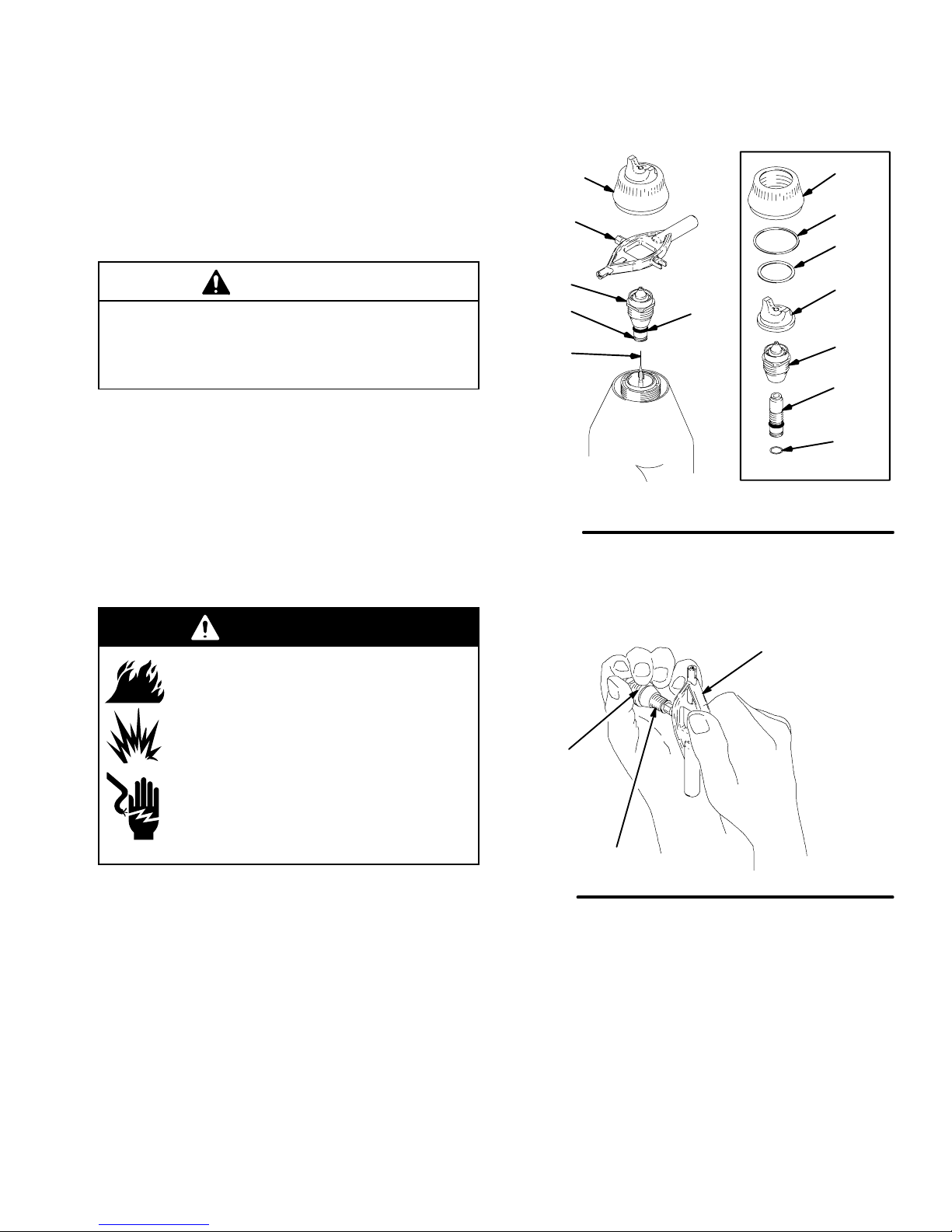
Clean the Air Cap and Fluid Nozzle
Equipment needed:
Soft bristle brush
Solvent compatible with fluid being sprayed
WARNING
PRESSURIZED EQUIPMENT
To reduce the risk of a serious injury,
follow the Pressure Relief Procedure
on page 16 when you stop spraying and
whenever you are instructed to relieve
the pressure.
Procedure:
1. Relieve the system pressure.
2. Remove the air cap assembly (1, 12) and gun
shroud (2). See Fig. 14.
3. Wipe the fluid nozzle (14), shroud (2), and exterior
of the gun (P) clean with a cloth dampened in
solvent. Avoid getting any solvent into the air
passages. Whenever possible, point the gun down
while cleaning it.
6. Slide the shroud (2) onto the gun (P). Make sure
the shroud o-ring (121) is in place.
7. Carefully install the air cap (12). Do not bend the
electrode (13) and be sure to insert the electrode
wire through the center air cap hole. Rotate the air
cap horns to the desired position.
8. Make sure the o-ring (8) is in place on the retaining
ring (1). Tighten the air cap retaining ring (1) until
the air cap is held firmly in place; you should not
be able to rotate the air cap horns by hand.
9. Test the gun resistance as instructed on page 26.
121
P
4. If it appears that there is paint inside the fluid
nozzle (14) air passages, remove the gun from the
line for servicing.
5. Clean the air cap (12) with the soft bristle brush
and solvent or submerge the air cap in suitable
solvent and wipe it clean.
CAUTION
Do not use metal tools to
clean the air cap or fluid
nozzle holes as this could
scratch them, and make
sure the electrode wire is not
damaged. Scratches in the
air cap or nozzle or a damaged electrode wire can distort the spray pattern.
03511
2
8
14
13
1
12
03897A
Fig. 14
308442 21
Page 22

Maintenance
Check for Fluid Leakage (See Fig. 15)
WARNING
FIRE AND EXPLOSION HAZARD
If any fluid leakage from the gun is detected, stop spraying immediately!
Fluid leakage into the gun shroud could
cause fire or explosion and result in
serious injury and property damage.
WARNING
PRESSURIZED EQUIPMENT
To reduce the risk of a serious injury,
follow the Pressure Relief Procedure
on page 16 when you stop spraying and
whenever you are instructed to relieve
the pressure.
During operation, periodically check the manifold
exhaust tube (YY) and both ends of the gun shroud
(ZZ) for the presence of fluid. Fluid in these areas
would indicate fluid leakage into the shroud, which
could be caused by leaks at the fluid tube connections
or fluid packing leakage.
If fluid is seen in any of these areas, stop spraying
immediately! Relieve the system pressure, then
remove the gun for repair.
Fig. 15
YY
ZZ
Check for signs of fluid leakage
where indicated by arrows.
ZZ
YY
Manifold Back View
03446
03445
22 308442
Page 23

Troubleshooting
WARNING
ELECTRIC SHOCK HAZARD
Installing and servicing this equipment
requires access to parts which may
cause an electric shock or other serious
injury if the work is not performed prop-
nance or service on the gun or system.
WARNING
PRESSURIZED EQUIPMENT
To reduce the risk of a serious injury,
follow the Pressure Relief Procedure
on page 16 before doing any mainte-
erly. Do not install or service this equipment unless
you are trained and qualified.
NOTE: Check all possible remedies in the Troubleshooting Charts before disassembling the gun.
Spray Pattern Troubleshooting
NOTE: Some spray pattern problems are caused by the improper balance between air and fluid.
PROBLEM CAUSE SOLUTION
Fluttering or spitting spray The fluid supply is insufficient.
The fluid nozzle is loose, or the fluid nozzle taper seat is damaged.
There is dirt between the fluid nozzle,
taper seat, and gun body.
The coupler at the fluid inlet is loose or
cracked.
Gun is spitting when triggered or
detriggered.
The air cap is damaged or dirty.
The actuator arm is out of position (it is too
close to the fluid needle).
The fluid seat is worn.
Adjust the fluid regulator, or fill the fluid
tank.
Tighten or replace the fluid nozzle; see
page 29.
Clean the parts; see page 21.
Tighten or repair the coupler .
Clean or replace the air cap; see page 21.
Reposition the actuator arm; see page 32.
Replace the fluid nozzle and/or electrode
needle; see page 29 and 30.
There is fluid buildup on the air cap; partially clogged horn holes; or full air pressure from the clean horn hole forces the
fan pattern toward the clogged end.
The electrode is bent.
The fluid nozzle or air cap holes are dam-
aged.
There is fluid buildup on the perimeter of
the fluid nozzle orifice, or a partially
clogged fluid nozzle orifice.
The electrode is bent.
The fan air pressure is too high.
The fluid is too thin.
There is not enough fluid pressure.
The fan air pressure is too low.
The fluid is too thick.
There is too much fluid.
Streaks The last coat of fluid is applied too wet.
There is too much air pressure.
The air pressure is insufficient.
Clean the air cap with a soft implement or
submerge it in water and wipe it clean;
see page 21.
Straighten the electrode.
Replace the damaged part; see page 29.
Remove the obstruction; never use wire
or hard instruments; see page 21.
Straighten the electrode.
Reduce the fan air pressure.
Increase the fluid viscosity.
Increase the fluid pressure.
Increase the fan air pressure.
Reduce the fluid viscosity.
Reduce the fluid flow.
Apply a drier finish using multiple strokes.
Decrease the air pressure.
Increase the air pressure.
The spray pattern is non-uniform.
Clean or replace the air cap; see page 21.
308442 23
Page 24

Troubleshooting
Gun Operation Troubleshooting
PROBLEM CAUSE SOLUTION
Fluid leakage from the fluid packing
area
Fluid leakage from the front of the
gun
“Orange Peel” finish The air pressure is insufficient.
Excessive spray fog The air pressure is too high.
No fluid sprays from the gun The fluid supply is low.
The fluid rod packings or fluid rod are
worn.
The fluid rod is worn or damaged.
The fluid seat is worn.
The resistor stud is loose.
The fluid nozzle is loose.
The resistor stud o-ring is damaged.
The fluid is poorly mixed or filtered.
An improper thinner is being used.
The fluid is thinned too much.
The fluid nozzle is dirty or clogged.
The fluid nozzle is damaged.
The piston is not actuating.
The actuator arm is out of position.
Replace the packings or rod; see page
31.
Replace the fluid rod; see page 31.
Replace the fluid nozzle and/or electrode
needle; see page 29 and 30.
Tighten the resistor stud; see page 29.
Tighten the fluid nozzle; see page 29.
Replace the o-ring; see page 29.
Increase the air pressure; use the least air
pressure needed for good results.
Remix or refilter the fluid.
Use the proper thinner.
Reduce the air pressure; use the least air
pressure needed for good results.
Properly thin the fluid.
Check the fluid supply; add fluid if
necessary.
Clean the fluid nozzle; see page 21.
Replace the fluid nozzle; see page 29.
Check the cylinder air; check the piston
u-cup; see page 32.
Check the actuator arm and nuts; see
page 33.
The equipment is covered with fluid The exhaust air flow is insufficient or not
directed properly.
The distance between the gun and work-
piece is incorrect.
Dirty air cap The electrode is bent.
The nozzle orifice is damaged.
The fluid is coming on before the air.
The air cap and fluid nozzle are misaligned.
Air
Cap
Fluid
Nozzle
ALIGNED MISALIGNED
Air leakage from the air cap The o-rings on the piston stem are worn. Inspect the o-rings; replace them as
Air leakage from the manifold The manifold gasket is damaged, or the
manifold is not tight.
Fluid leakage at the quick-disconnect The manifold is not tight.
The o-rings on the fluid hose are worn or
missing.
Check for the proper CFM; check the
baffles and direction of the air flow.
Adjust the spraying distance to 8 to 12
inches (203 to 305 mm).
Straighten the electrode.
Replace the fluid nozzle; see page 29.
Check the actuator arm and nuts; see
page 33.
Check the air cap and fluid nozzle seat for
fluid buildup. Clean or replace parts as
needed; see page 21 or 29.
needed; see page 32.
Replace the gasket or tighten the manifold
screws; see page 37.
Tighten the manifold screws; see page
37.
Inspect or replace the o-rings.
24 308442
Page 25

Troubleshooting
Electrical Troubleshooting
PROBLEM CAUSE SOLUTION
Poor wrap-around The turbine air is not on.
The distance between the gun and
workpiece is incorrect.
The parts are poorly grounded.
Booth exhaust velocity is too high.
The atomizing air pressure is too high.
The fluid pressure is too high.
The fluid viscosity is not right for electros-
tatic spray.
The voltage output is too low.
The turbine alternator is not operating.
The gun resistance is faulty.
Fluid leaks from the fluid rod packing and
causes a short.
The turbine alternator is faulty.
The KV switch is stuck on low.
The operator gets a shock The operator is not properly grounded or
is near an ungrounded object.
The gun is not properly grounded.
The operator gets a shock when
touching the workpiece
The workpiece is not properly grounded. Clean the workpiece hangers; check for
Turn on the turbine air.
Adjust the spraying distance to 8 to 12
inches (203 to 305 mm).
Clean the workpiece hangers; check for
proper grounding on the conveyor or track.
Reduce the exhaust velocity within the
code limits.
Reduce the atomizing air pressure.
Reduce the fluid pressure.
Check with the supplier for proper fluid
viscosity for electrostatic spray.
Check the possible causes listed below.
Check the air supply to the gun.
Check the gun resistance; see page 26.
Clean the fluid rod cavity, replace the
packing; see page 31.
Be sure the plug is in place on the back of
the turbine alternator housing; remove
and test the turbine alternator; see
page 36.
Check the switch actuation; replace the
KV switch if necessary.
Be sure the floor and the operator are
properly grounded; see Ground the Sys-
tem, page 13.
See Check the Electrical Grounding,
page 14.
proper grounding on the conveyor or
track.
No or low voltage output reading on
the gun ES (KV) display module
The fiber optic cable or connection is
damaged.
The turbine air is not on.
Check the cables and connections;
replace the parts if they are damaged.
Turn on the turbine air.
See other causes under Problem - Poor
wrap-around, above.
Refer also to the Graco ES display mod-
ule manual 308265.
308442 25
Page 26
Electrical Tests
The performance and safety of the spray gun are
directly affected by the condition of the electrical
components contained inside the gun. The following
electrical tests can be used to determine the condition
of the power supply (27) and the resistor stud (15), as
well as the continuity of the electrical path between the
components.
Flush the gun fluid passages with solvent and air. To
get an accurate reading, the fluid hose must not have
any fluid in it.
Use part no. 241079 megohmmeter (L) and an applied
voltage of 500 volts to complete these electrical tests.
Connect the leads as shown.
WARNING
FIRE, EXPLOSION, AND
ELECTRIC SHOCK HAZARD
Megohmmeter P/N 241079 is not approved for use in a hazardous area. To
reduce the risk of sparking, do not use
the megohmmeter to do electrical tests
unless:
Test Gun Resistance (See Fig. 16)
Measure the resistance between the end of the electrode (13) and the gun body (29). The resistance
should be between 329 to 401 megohms. If the resistance is outside the specified range, go to the next
test. If the resistance is correct, refer to Electrical
Troubleshooting on page 25 for other possible
causes of poor performance.
L
29
The gun has been removed from the
hazardous area (see page 28 to remove gun);
Or all spraying devices in the hazardous area
are turned off, ventilation fans in the hazardous
area are operating, and there are no flammable
vapors in the area (such as open solvent containers or fumes from spraying).
Failure to follow this warning could cause fire,
explosion, electric shock and result in serious injury
and property damage.
13
03898B
Fig. 16
26 308442
Page 27

Electrical Tests
T est Power Supply Resistance (See Fig. 17)
Remove the power supply (27) from the gun body (29)
as instructed on page 35.
Measure the resistance from the power supply’s
ground contact point (R) to the contact inside of the
power supply seal (D) [the conductive rubber contact
may be slightly recessed into the seal].
The resistance should be 297 to 363 megohms. If the
resistance is outside the specified range, the power
supply is defective and must be replaced. If the resistance of the power supply is correct, proceed to the
next test.
NOTE: Be sure the seal (D) is in place on the end of
the power supply before installing the power supply
back into the gun.
Test Resistor Stud Resistance (See Fig. 18)
Remove the resistor stud (15) as instructed on page
29. Check the resistance between the black resistor
stud ring contact (S) and the needle contact ring (T).
You may have to press down on the contact ring (S) in
several places to get a good reading.
Fig. 17
L
R
D
27
0441
The resistance should be 21 to 29 megohms. If the
resistance is correct, make sure the metal contact in
the gun barrel and the needle contact ring (T) are
clean. If the resistance is outside the specified range,
the resistor is defective and the resistor stud (15) must
be replaced. See page 29 to replace the resistor stud.
WARNING
FIRE, EXPLOSION, AND
ELECTRIC SHOCK HAZARD
The resistor stud contact ring (S) is a
conductive contact ring, not a sealing
o-ring. See Fig. 18. To reduce the risk of
sparking, which could cause a fire,
explosion, or electric shock, do not
remove the resistor stud contact ring (S)
or operate the gun without the contact
ring in place. If the resistor stud (15) is
being replaced, only use a genuine
Graco part.
Fig. 18
15
S
T
0442
308442 27
Page 28

Service
Tools Included with the Gun
Ball End Wrench
Multi-tool
Prepare the Gun for Service
NOTE:
Check all the possible remedies in Troubleshoot-
ing, pages 23 to 25, before disassembling the gun.
WARNING
PRESSURIZED EQUIPMENT
To reduce the risk of a serious injury,
follow the Pressure Relief Procedure
on page 16 when you stop spraying,
before servicing the gun, and whenever you are
instructed to relieve the pressure.
1. Flush the gun with a compatible solvent.
If the plastic parts of the gun must be held in a vise,
use padded vise jaws to avoid damaging parts.
WARNING
EQUIPMENT MISUSE HAZARD
Do not mix or install parts from different
PRO gun models. Some PRO 5500hc
Gun parts look similar to other PRO Gun
parts but they have different part numbers and they are not interchangeable.
Use of parts other than those specified
in the PRO 5500hc Gun parts list on
page 39 could alter the grounding conti-
nuity of the gun, cause parts to leak or
rupture, or cause the gun to malfunction, which
could result in a fire, explosion, or electric shock.
WARNING
FIRE, EXPLOSION, AND
ELECTRIC SHOCK HAZARD
To reduce the risk of a fire, explosion, or
electric shock:
Be sure the turbine air (TA) is off
before flushing the gun or any part of
the system.
Clean all the parts with a compatible
solvent that is suitable for electrostatic equipment.
Do not service this equipment unless you are
trained and qualified.
Do not touch the gun nozzle or come within 4
inches (101.6 mm) of the nozzle during gun
operation.
2. Relieve the system pressure.
3. The service area must be clean. Remove the gun
from the worksite as instructed in the following
steps.
4. Loosen the bottom gun screw (21) until the gun (B)
sits loosely in the mounting bracket slot (A). Refer
to Fig. 19.
CAUTION
The piston return spring (105) is compressed
between the manifold (101) and gun body when they
are assembled. To avoid sudden movement of the
gun, loosen the bottom gun screw (21) before loosening the three manifold bolts (106). This allows the
gun to move forward gradually as the manifold bolts
are loosened. Hold the gun firmly in hand while
loosening the manifold bolts.
5. Holding the gun (B) firmly in hand, loosen the three
bolts (106) from the back of the manifold (101)
with the ball end wrench (77–not shown).
6. Remove the gun (B) from the manifold (101), and
take it to the service area.
105
A
106
101
CAUTION
Methylene chloride is not recommended as a flushing or cleaning solvent with this gun as it will damage
nylon components.
28 308442
Fig. 19
102
B
21
03218
Page 29
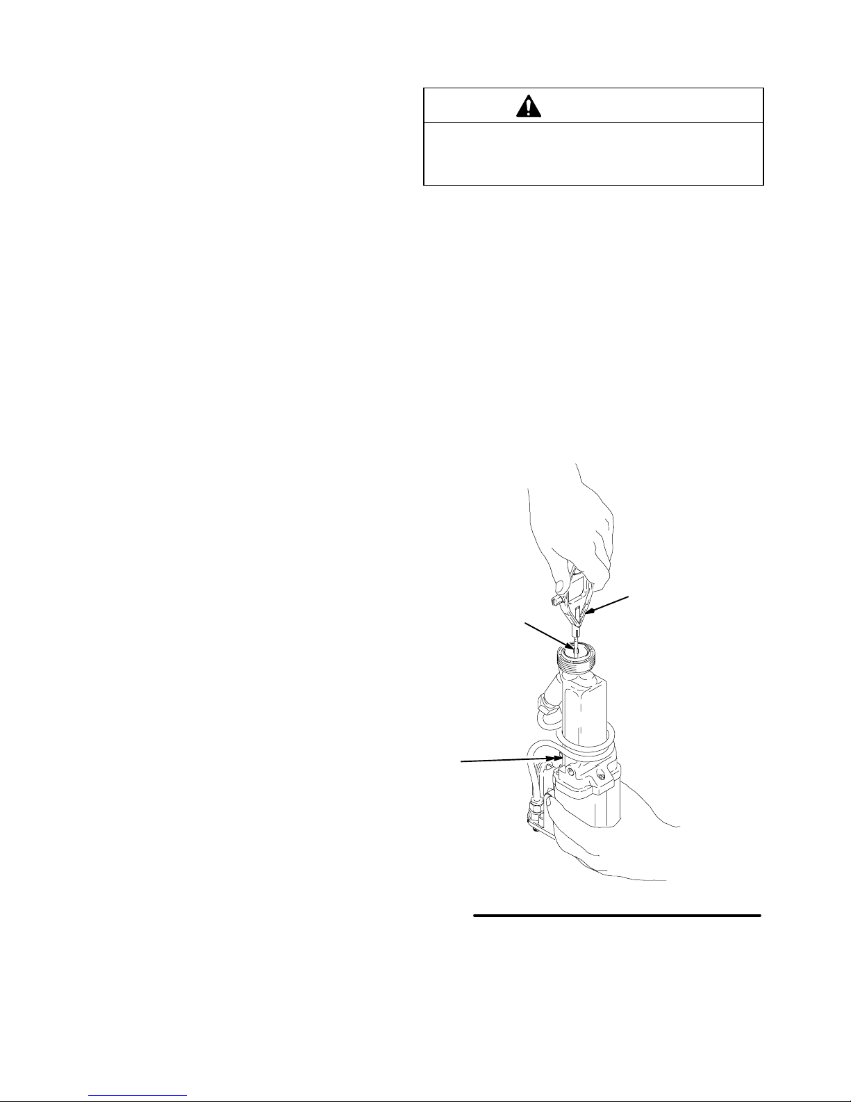
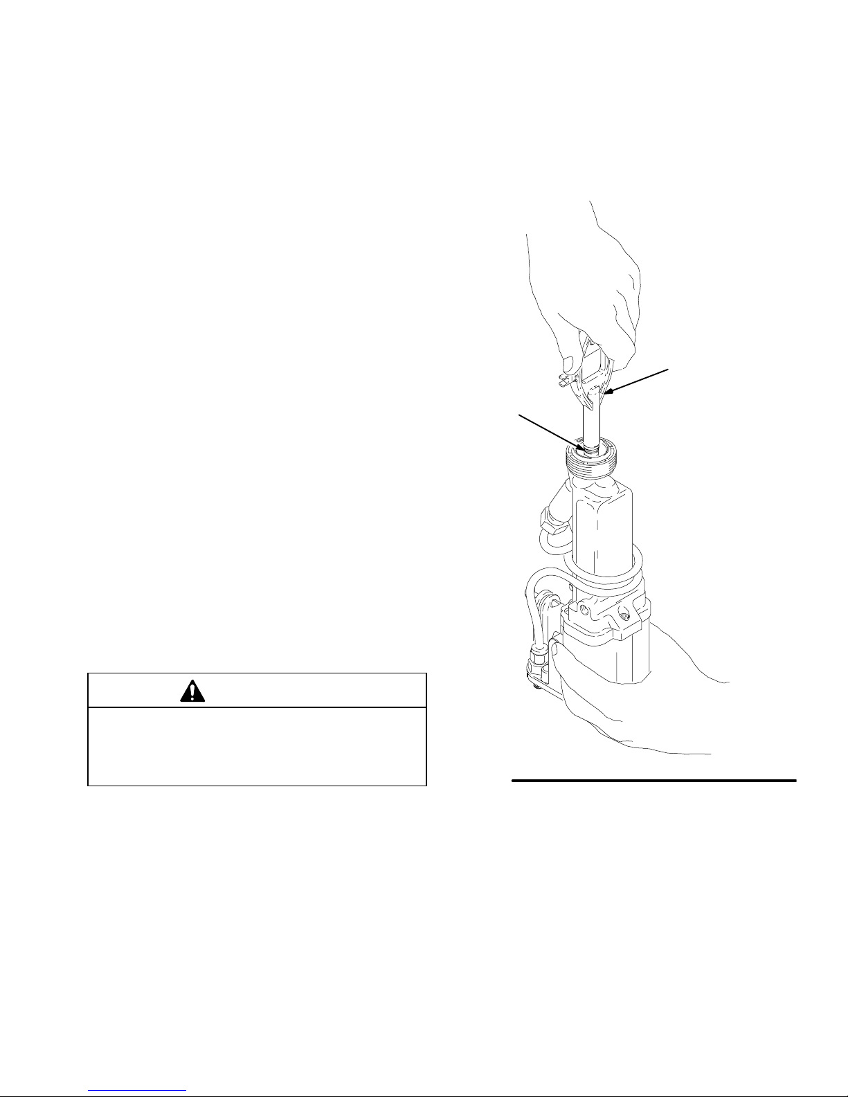
Air Cap/Nozzle/Resistor Stud
Replacement
Service
Apply a very light coat of lubricant to the o-ring (16).
Tighten the nozzle (14) hand-tight, then 1/8 to 1/4 turn more.
1. Prepare the gun for service as instructed on
page 28.
2. Point the front end of the gun up while removing
the air cap assembly (1, 3, 9, 12). See Fig. 20.
CAUTION
Hold the front end of the gun up while removing the
nozzle and resistor stud to help drain the gun and
prevent any fluid left in the gun from entering the air
passages.
3. Remove the fluid nozzle (14) with the multi-tool
(83).
The resistor stud (15) should come out with the
fluid nozzle. If the resistor stud remains in the gun,
start the nozzle threads onto the resistor stud and
pull it out.
4. Unscrew the resistor stud (15) from the fluid
nozzle (14) with the multi-tool (83). See Fig. 21.
WARNING
FIRE, EXPLOSION, AND
ELECTRIC SHOCK HAZARD
The resistor stud contact ring (S) is a
conductive contact ring, not a sealing
o-ring. See Fig. 20. To reduce the risk of
sparking or electric shock, do not
remove the contact ring (S) from the
resistor stud or operate the gun without
the contact ring in place. If the resistor
stud (15) is being replaced, only use a
genuine Graco part.
5. Lightly lubricate the o-ring (16) with petroleum jelly
and install it on the resistor stud (15). See Fig. 20.
1, 3, 9,12
83
14
15
13
Fig. 20
Tighten the resistor stud (15) into the nozzle (14) to 10 in-lbs (1.15
Nm).
14
15
Fig. 21
S
83
1
9
3
12
14
15
16
03455A
0444A
Continued on the next page.
308442 29
Page 30
Air Cap/Nozzle/Resistor Stud
Replacement (continued)
Service
CAUTION
6. Make sure the electrode needle (13) is tightened
properly. Refer to Fig. 22.
7. Install the resistor stud (15) in the fluid nozzle (14).
Tighten to 10 in-lb (1.12 Nm). See Fig. 21, page
29.
8. Install the fluid nozzle (14) and resistor stud (15)
assembly with the multi-tool (83). See Fig. 20,
page 29. Tighten until the fluid nozzle seats in the
gun barrel (1/8 to 1/4 turn past hand-tight).
9. Carefully install the air cap (12). Avoid bending the
electrode wire (13) and be sure to insert the electrode wire through the center air cap hole. Rotate
the air cap horns to the desired position.
10. Make sure the o-ring (9) is in place on the retaining
ring (1). Tighten the air cap retaining ring (1) until
the air cap is held firmly in place; you should not
be able to rotate the air cap horns by hand.
11. Test the gun resistance as instructed on page 26.
12. Install the gun onto the manifold and bracket as
instructed on page 37.
To avoid damaging the plastic threads or contact
wire, be very careful when installing the electrode
needle.
5. Install the gun shroud.
6. Install the fluid nozzle, resistor stud, and air cap
assembly as instructed at left.
7. Test the gun resistance as instructed on page 26.
8. Install the gun onto the manifold and bracket as
instructed on page 37.
Apply low-strength (purple) Loctite or equivalent to the fluid rod
threads, then install the electrode needle (13) finger-tight; do not
over-tighten.
Electrode Needle Replacement
1. Prepare the gun for service as instructed on
page 28.
2. Remove the air cap, nozzle and resistor stud as
instructed on page 29. Remove the gun shroud.
3. Unscrew and remove the electrode needle (13)
with the multi-tool (83). See Fig. 22. Be careful not
to damage the contact wire.
If the fluid rod turns, hold the back end of the fluid
rod (C).
4. Apply low-strength (purple) Loctite or equivalent
thread sealant to the fluid rod threads.
Hold the back end of the fluid rod (C) to prevent it
from turning while installing the new electrode
needle (13) finger-tight. Do not over-tighten the
electrode needle.
C
Fig. 22
83
13
03899A
30 308442
Page 31
Service
Fluid Packing Rod Removal and Repair
NOTE: The fluid packing rod can be replaced as
individual parts or as an assembly. If the assembly is
purchased, it is pre-adjusted at the factory.
1. Prepare the gun for service as instructed on
page 28.
2. Remove the air cap assembly and the gun shroud.
3. Remove the jam nut (46) and actuator arm (19).
See Fig. 25, page 32.
NOTE: The fluid nozzle must be in place when removing or installing the jam nut and actuator arm.
4. Remove the fluid nozzle, resistor stud, and electrode needle as instructed on page 29.
5. Remove the fluid packing rod assembly (28) with
the multi-tool (83). See Fig. 23.
7. If the parts are purchased separately, assemble
them as instructed in steps 8 to 11 and as shown
in Fig. 24, on page 32.
If installing the complete fluid rod assembly, go to
step 12, page 32.
83
28
6. Clean all the parts, and check them for wear or
damage. Replace the parts if necessary.
Before installing the fluid packing rod assembly
(28), clean the internal surfaces of the barrel with a
soft brush or cloth. Check the inside of the barrel
for marks from high voltage arcing. If the marks
are present, replace the barrel.
CAUTION
Clean all the parts in non-conductive solvent compatible with the fluid being used, such as xylol or mineral
spirits. Use of conductive solvents can cause the gun
to malfunction.
Fig. 23
03902A
Continued on the next page.
308442 31
Page 32

Service
Fluid Packing Rod Removal and Repair
(continued)
8. Place the packing nut (28c) and o-ring (28g) on the
fluid rod (28b). The flats on the packing nut must
be facing toward the back of the fluid rod.
9. Fill the entire inner cavity of the spacer (28d) with
petroleum jelly. Place the spacer on the fluid rod
(28b), in the direction shown in Fig. 24. Generously apply petroleum jelly to the outside of the
spacer.
10. Place the fluid packing (28f), needle packing (28e),
and housing (28a) on the fluid rod (28b) as shown
in Fig. 24.
11. Lightly tighten the packing nut (28c) with the
multi-tool (83). The packing nut is properly tightened when there is 2 lbs. (9 N) of drag force when
sliding the packing housing (28a) assembly along
the shaft. Tighten or loosen the packing nut as
needed.
12. Lubricate the o-ring (28h) on the outside of the
packing housing (28a).
13. Make sure the spring (11) is installed against the
nut (U) as shown in Fig. 24.
14. Install the fluid packing rod assembly (28) into the
gun barrel. Using the multi-tool (83), tighten the
assembly until it is just snug, then check the drag
on the fluid rod. See Fig. 23, page 31.
15. Install the electrode needle, fluid nozzle and resistor stud as instructed on page 30.
16. Install and adjust the actuator arm (19) and jam
nut (46) as instructed on page 33.
17. Test the gun resistance as instructed on page 26.
18. Install the gun shroud and air cap assembly.
19. Install the gun onto the manifold and bracket as
instructed on page 37.
Apply a very light coat of lubricant to the o-ring (28h).
Fill the inner spacer (28d) cavity with petroleum jelly and gener-
ously lubricate the outside of the spacer.
28h
28f
28e
28b
Fig. 24
28a
28d
28g
28c
Piston Repair
1. Prepare the gun for service as instructed on
page 28.
2. Remove the air cap assembly and the gun shroud.
3. Remove the jam nut (46), actuator arm (19), and
adjustment nut (36). See Fig. 25.
NOTE: The fluid nozzle must be in place when removing or installing the jam nut and actuator arm.
Tighten the packing nut (28c) to 2 lbs (9 N) of drag force.
The spring (11) is not included with the fluid packing rod assembly
(28).
11U
28
46 19 36 23g
Fig. 25
03224
03904A
32 308442
Page 33

Service
Piston Repair (continued)
4. Push on the piston rod (23g) to push the piston
assembly out the back of the gun.
5. Inspect the o-rings (23a, 23b, 23c) and u-cup
packing (23f) for damage. See Fig. 27. Refer to
Fig. 28 to isolate any air leakage problems.
6. Lubricate the o-rings (23a, 23b, 23c) and u-cup
packing (23f) with petroleum jelly.
7. Align the two stems (23d) with the holes in the gun
body and press the piston assembly into the back
of the gun until it bottoms.
8. Installing the Actuator Arm and Nuts:
a. Install the adjustment nut (36), actuator arm
(19), and jam nut (46) onto the piston rod
(23g). See Fig. 25.
NOTE: The jam nut (46) has a slightly larger hex and a
thinner profile than the adjustment nut (36).
b. Thread the jam nut (46) flush with the end of
the piston rod (23g).Tighten the adjustment nut
(36) against the actuator arm (19). When
properly assembled, there should be about a
0.125 in. (3 mm) gap between the actuator
arm (19) and the fluid packing rod nut (U),
which allows the atomizing air to actuate
before the fluid actuates. See Fig. 26. In
addition, there should be 3 to 4 mm of electrode needle travel when the gun is triggered.
If necessary, adjust the jam nut (46) position to
obtain these dimensions.
9. Test the gun resistance as instructed on page 26.
10. Install the gun shroud and air cap assembly.
11. Install the gun onto the manifold and bracket as
instructed on page 37.
Apply a very light coat of lubricant to the o-rings (23a, 23b, 23c)
and u-cup (23f).
Align the two stems (23d) with the holes in the gun body and
press the piston assembly until it bottoms.
23d
23c
23b
23e
23f
23g
23a
Fig. 27
Description Function
O-Ring (23a)
Shaft Air Seal
O-Ring (23b)
Front Air Seal
O-Ring (23c)
Back Air Seal
U-cup (23f)
Cylinder Air
Seal
It seals the cylinder air along the piston
rod. If the air leaks along the piston rod
(23g), replace this o-ring (23a).
It is the air shut-off seal. If the air leaks
from the air cap when the gun is detriggered, replace these o-rings.
It separates the cylinder air pressure from
the fan and atomizing air pressure.
If the air leaks from the small vent hole in
the back of the manifold when the gun is
triggered, replace the u-cup.
23c
23b
03530
There should be a 0.125 in. (3 mm) gap between the actuator arm
(19) and the fluid packing rod nut (U).
19 U
Fig. 26
04823
Fig. 28
Fan Air Side
23f
23a
Atomization Air Side
03531
308442 33
Page 34

Service
Barrel Removal
1. Prepare the gun for service as instructed on
page 28.
2. Remove the air cap assembly and the shroud from
the gun.
3. Carefully loosen the fluid fitting nut (43). See
Fig. 30. Pull the tube (33) out of the fitting. Make
sure that both ferrules and the nut stay with the
tube.
26
24
4. Remove the jam nut (46) and actuator arm (19).
NOTE: The fluid nozzle (14) must be in place when
removing or installing the jam nut and actuator arm.
5. Loosen the three screws (24) with the ball end
wrench (77–not shown). See Fig. 29.
6. Hold the gun body (29) with one hand and pull the
barrel (26) straight away from the body to remove
it.
CAUTION
To avoid damaging the power supply (27), pull the
gun barrel straight away from the gun body. If necessary, gently move the barrel from side to side to free
the power supply from the gun body.
14
26
Fig. 29
29
27
03900A
29
Fig. 30
34 308442
46 19 36
33
43
03904A
Page 35

Service
Power Supply Removal and Replacement
NOTES:
To avoid a loss in electrostatic performance, inspect
the gun body power supply cavity for dirt or moisture. Clean the cavity with a clean, dry rag.
Do not expose the seal (D) or gasket (27a) to
solvents as this will damage them.
1. Prepare the gun for service as instructed on
page 28.
2. Remove the barrel as instructed on page 34.
3. Grasp the power supply (27) with your hand. With
a gentle side-to-side motion, being careful not to
damage the power supply, pull the power supply
free from the gun body (29), then pull it straight
out. See Fig. 31.
4. Inspect the power supply for any physical damage.
Check the electrical resistance as instructed in
Test Power Supply Resistance, page 27. If
necessary, replace the power supply.
5. Before installing the power supply, inspect the seal
(D) for any damage or swelling. Make sure the
gaskets and pads (27a–27f) are in place.
6. Lubricate the o-ring (25a) and insert the power
supply in the gun body.
7. Assemble the gun as instructed in Barrel
Installation, page 36.
Power Supply Adjustment
The kV switch, in the manifold, enables you to switch
between full voltage and a lower voltage output. The
lower voltage is factory set at 60 kV, but can be
adjusted between 45 and 80 kV.
To adjust the low voltage setting, use a small blade
end screw driver to turn the potentiometer (W). Turn it
clockwise to decrease the voltage or counterclockwise
to increase the voltage; fully clockwise is 45 kV, fully
counterclockwise is 80 kV.
Apply a very light coat of lubricant to the o-ring (25a).
Do not expose the seal (D) or gasket (27a) to solvents.
26
Fig. 31
27a
27
27b
W
D
27f
27c
V
25b
30
29
25a
25
03903B
308442 35
Page 36

Service
Turbine Alternator Removal and
Replacement
NOTE: Replace the turbine bearings after 2000 hours
of operation. See your authorized Graco representative.
1. Prepare the gun for service as instructed on
page 28.
2. Remove the power supply from the gun body as
instructed on page 35.
3. Squeeze the two ends of the retaining ring (30)
together and carefully pull the alternator (25) away
from the power supply (27) until the wire connector
(V) disengages. See Fig. 31, page 35.
4. Use an ohmmeter to test the turbine alternator coil.
Measure the resistance between the two outer
terminals of the 3-wire connector (V). Resistance
should be 3 to 5 ohms. If the reading varies from
this value, replace the alternator.
Barrel Installation
1. Be sure the gaskets (20, 27a) and spring (11) are
in place. See Fig. 32. Replace the parts if they are
damaged.
2. Place the barrel (26) over the power supply (27)
and onto the gun body (29). Make sure the fluid
needle spring (11) is seated properly.
3. Using the ball end wrench (77–not shown), tighten
the three screws (24) oppositely and evenly to 18
in-lbs (2 Nm) maximum (about a half turn past
snug); do not over-tighten.
CAUTION
To avoid damaging the gun, do not over-tighten the
screws (24).
4. Install the fluid tube back into the fluid fitting (4)
and tighten the nut (43).
5. Install and adjust the actuator arm (19) and jam
nut (46) as instructed on page 33.
5. Connect the 3-wire connector to the 3 prongs in
the power supply. Push the alternator (25) onto the
power supply (27) until the retaining ring (30)
engages with the alternator.
6. Install the power supply in the gun body as
instructed on page 35.
7. Assemble the gun as instructed at right.
NOTE: Make sure the entire fluid tube (33) is clear
of the actuator arm to avoid having the tube rub
against it during operation.
6. Test the gun resistance as instructed on page 26.
7. Install the gun shroud and air cap assembly.
8. Install the gun onto the manifold and bracket as
instructed on page 37.
36 308442
Page 37

Service
Tighten the screws (24) to 18 in-lbs (2 Nm) maximum (about half
turn past snug), using the wrench (77) provided.
Install the nut (46) flush to the end of the piston rod (23g).
20
24
33
26
13
Fig. 32
27
Adjust the nut (36) to create 0.125 in. (3 mm) gap between the
actuator arm (19) and the nut.
Make sure the entire fluid tube (33) is clear of the actuator
arm (19).
29
27a
43
36
23g
19
46
11
4
03901A
Install the Gun onto the Manifold
1. Make sure the gaskets (108, 121), and spring
(105) are in place on the manifold (101). See Fig.
33. Inspect the parts for damage and replace them
as needed.
2. Secure the gun (B) to the manifold (101) by tightening the three screws (106) with the ball end
wrench (77–not shown).
3. Secure the gun (B) to the mounting bracket (102)
by tightening the screw (21) with the ball end
wrench (77).
Fig. 33
121
108
B
105
102
21
308442 37
106
101
03218
Page 38

Standard Spray Gun Parts
Part No. 236685
Standard PRO 5500hc Spray Gun
Item 23 includes 23a–23g
Item 25 includes 25a & 25b
Item 27 includes 27a–27f
Item 28 includes 28a–28h
3
9
1
24
26
12
20
14
28a, 28c–28h
See page 39
13
16
15
27f
27b
2
27c
27
28b
28
25a
25
25b
30
6
46
27a
33
5
REF 33
18
11
7
36
19
29
17
32
23d
23c
23b
23a
10
5
4
21
23e
23f
23g
75
REF 33
38 308442
43
35 34
03905B
Page 39

Standard Spray Gun Parts
Ref.
WARNING
No. Part No. Description Qty.
Some PRO 5500hc Gun replacement parts look similar to
other PRO Gun parts but are not interchangeable! When
servicing, do not mix or use other PRO Gun parts!
Use of parts other than those specified in the parts list
below could alter the grounding continuity of the gun,
cause parts to leak or rupture, or cause the gun to
malfunction and result in serious injury, fire, explosion or
property damage.
Part No. 236685
Standard PRO 5500hc Spray Gun;
Includes items 1–85
Ref.
No. Part No. Description Qty.
1 189768 RET AINING RING, air cap 1
2 189770 SHROUD 1
3 189786 GASKET, air cap nut 1
4 189549 FITTING, fluid, quick-disconnect 1
5* 111450 O-RING; fluoroelastomer 2
6 189367 CAP, exhaust 1
7 185122 MUFFLER/FLAME ARRESTOR 1
9 110492 O-RING, PTFE
10 108290 SCREW 1
1 1 185111 SPRING, compression 1
12 193033 AIR CAP; See Manual 307803 for
available air caps 1
13 190933 NEEDLE, electrode 1
14 191833 NOZZLE, fluid; See Manual 307803
for available nozzles 1
15 223977 STUD, resistor 1
16* 1 11507 O-RING; fluoroelastomer 1
17 186818 FITTING, fluid 1
18* 102982 O-RING; PTFE 1
19 186766 ARM, actuator 1
20 185113 GASKET, manifold; polyethylene 1
21 112689 SCREW, socket; 1/4 x 0.75” 1
23 236826 PISTON ASSY;
Includes items 23a–23g 1
23a 111508
23b 111504 O-RING; fluoroelastomer 2
23c 112319
23d 189355 STEM, piston 2
23e 189747
23f 189752 PACKING, u-cup; UHMW
23g 189754
24 185096 SCREW, cap, relieved; M5 x 0.8 3
25 222319 ALTERNATOR, turbine
25a 110073
25b 185124
26 223940 BARREL, gun 1
27 224093 POWER SUPPLY ASSY; 85 kV
O-RING; fluoroelastomer 1
O-RING; fluoroelastomer 2
PISTON 1
polyethylene 1
ROD, piston 1
Includes items 25a & 25b 1
O-RING, Viton 1
CUSHION 1
Includes items 27a–27f 1
1
27a 186840
27b 185099
27c 185145
27f 192361
28 224747 PACKING ROD ASSY
28a 185495
28b 223981
28c 185488
28d* 186069
28e 178763
28f* 178409
28g* 111504
28h* 111316
29 190055 BODY, gun 1
30 185114 RETAINER RING, alternator 1
32* 103337 O-RING, Viton 2
33 TUBE; PTFE 1
34* 111286 FERRULE 1
35* 111285 FERRULE 1
36 102025 NUT, hex; 1/4”-20 1
37 112638 FITTING, fiber optic (shown on
43 112644 NUT ; for 1/4” O.D. tube fitting 1
46 101324 NUT, hex jam; 1/4”–20 1
75 236830 MANIFOLD ASSY.
77 107460 WRENCH, ball end 1
78 180060 SIGN, warning, English
83 191744 MULTI-TOOL 1
84 179791 TAG, warning 1
85 189888 COVER, gun 1
* These parts are included in Fluid Seal Repair Kit 237543,
which may be purchased separately.
These parts are included in Air Seal Repair Kit 236827,
which may be purchased separately.
These parts are not shown in the parts drawing.
Replacement Danger and Warning labels, tags and cards
are available at no cost.
The coiled fluid tube parts (5, 17, 18, 32, 33) are available
as an assembly. Order part no. 237298.
REF NO. 28, Packing Rod Assembly
Includes items 28a–28h
GASKET, power supply 1
PAD 1
PAD 2
PAD 1
Includes items 28a–28h 1
HOUSING, packing 1
ROD, fluid 1
NUT, packing 1
SPACER, packing 1
PACKING, rod 1
PACKING, fluid 1
O-RING, fluoroelastomer 1
O-RING, fluoroelastomer 1
page 40) 1
See separate parts list on page 41 1
See Accessories for additional signs 1
28c
28g
28d
28f
28e
28a
28h
0601
308442 39
Page 40
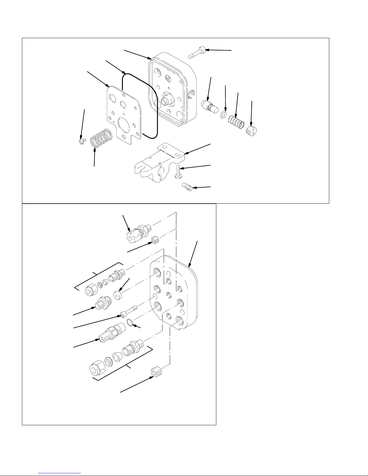
Manifold Parts
Front View
Back View
113
108
109
105
107
121
101
37
115
114
Ref. 101
106
110
110a
122
111
102
104
103
Apply low strength (purple) Loctite or an
equivalent sealant to the threads.
Press fit the spring (105)
Tighten the fitting until the hex bottoms against
the manifold.
This fitting (113) has left-hand threads.
Install the KV cap (111) flush to the outside
surface.
Concave side of the disk (114) faces toward
the manifold.
Replace the spring (122) every 300,000
cycles.
An optional fiber optic fitting (37) is included
with the gun assembly; see page 39. Remove
the plug (115) and install the fitting (37) if a KV
display is being used.
03462
106
117
116
40 308442
118
112
03226
Page 41

Manifold Parts
WARNING
Some PRO 5500hc Gun replacement parts look similar to
other PRO Gun parts but are not interchangeable! When
servicing, do not mix or use other PRO Gun parts!
Use of parts other than those specified in the parts list
below could alter the grounding continuity of the gun,
cause parts to leak or rupture, or cause the gun to
malfunction and result in serious injury, fire, explosion or
property damage.
Part No. 236830 Gun Manifold
For Standard PRO 5500HC Spray Gun;
Includes items 101–122
Ref.
No. Part No. Description Qty.
101 190056 MANIFOLD 1
102 189581 MOUNTING BRACKET 1
103 110465 BOLT, square head 2
104 112689 SCREW; 1/4–20 x 0.75” 2
105 112640 SPRING, compression 1
106 186846 BOLT, manifold; M5 x 0.8 3
107 111157 FITTING, tube; for 1/4” OD tube 3
108 189363 GASKET, manifold 1
109 108290 SCREW; 8–32 x 1/4” 2
110 236696 KV SWITCH; Includes item 110a 1
110a 111316 O-RING, fluoroelastomer 1
1 11 189365 KV CAP 1
112 110078 FITTING, tube; for 3/8” OD tube 2
113 186845 FITTING, turbine; 1/4–18 npsm
left hand thread 1
114 107107 DISK, regulator 1
1 15 112645 PLUG; 1/8–27 npt 1
1 16 112646 PLUG; 5/8–18 x 5/8” 1
1 17 189551 FLUID FITTING, quick-disconnect 1
118* 111450 O-RING; CV–75 1
121 190301 GASKET, foam 1
122 112641 SPRING 1
Part No. 236852 Optional Fiber Optic Kit
The kit is not included with the gun. The kit is only for
use with the ES Display Part No. 224117 to improve
light transmission when two bulkhead splices are used.
The kit includes items 201–203.
Ref.
No. Part No. Description Qty.
201 112638 FITTING, fiber optic; see item 37 on
page 40 1
202 111224 LENS 1
203 189875 SLEEVE 1
202
203
04798
* These parts are included in Fluid Seal Repair Kit 237543,
which may be purchased separately.
These parts are included in Air Seal Repair Kit 236827,
which may be purchased separately.
Optional gaskets are available:
Part No. 111180: Viton
308442 41
Page 42
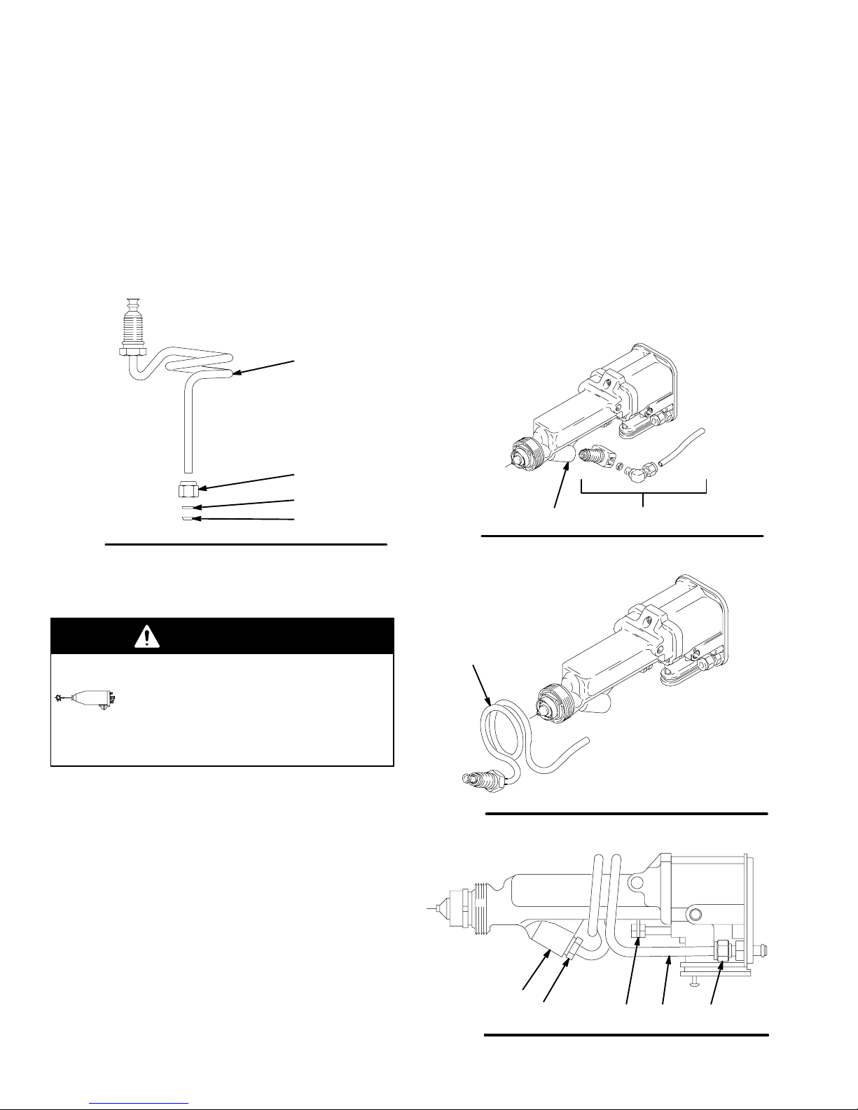
Kit Parts and Installation
Part No. 237300
PRO 5500hc Conversion Kit; To convert the PRO
5500sc spray gun to the PRO 5500hc spray gun;
Includes items 201–204
Ref.
No. Part No. Description Qty.
201 237297 COILED TUBE ASSY. 1
202 112644 NUT ; nylon; for 1/4 ” O.D. tube 1
203 111285 FERRULE; nylon 1
204 111286 FERRULE; nylon 1
201
202
203
204
Fig. 34
03933A
7. Position the coiled tube assembly so its threaded
inlet fitting (C) is aligned with the barrel fluid inlet
(A), then tighten the fitting into the inlet as shown
in Fig. 37.
8. Slide the nylon nut (202) and ferrules (203 & 204)
onto the coiled tube assembly (201). See Fig. 34.
9. Install the coiled tube assembly (201) into the fluid
fitting and tighten the nut (202). See Fig. 37. Make
sure the entire tube is clear of the actuator arm (D)
to avoid having the tube rub against it during operation.
10. Install the gun onto the manifold as instructed on
page 37.
Fig. 35
A B
03934
Installing the PRO 5500hc Conversion Kit
WARNING
PRESSURIZED EQUIPMENT
To reduce the risk of a serious injury,
follow the Pressure Relief Procedure
on page 16 when you stop spraying,
before servicing the gun, and whenever you are
instructed to relieve the pressure.
1. Flush the gun with a compatible solvent.
2. Relieve the system pressure.
3. Prepare the gun for service as instructed on page
28.
4. Remove the PRO 5500sc gun’s fluid tube, fittings,
o-rings, and spacer (B). See Fig. 35.
5. Clean the barrel fluid inlet (A) with compatible solvent. Inspect the barrel fluid inlet for damage and
replace if needed.
6. Slide the coils of the tube assembly (201) over the
front of the gun barrel, until it is past the barrel fluid
inlet (A). See Fig. 36 and 37.
42 308442
201
Fig. 36
Fig. 37
03935A
A
C
202D 201
03904A
Page 43

Technical Data
Category Data
Gun Weight (gun
3.57 lb (1620 g)
and manifold)
Maximum Working
100 psi (7 bar, 0.7 MPa)
Pressure
Air Pressure
Operating Range
Fluid Pressure
Operating Range
0–100 psi (0–7 bar,
0–0.7 MPa)
0–100 psi (0–7 bar,
0–0.7 MPa)
Voltage Output 0–85 kV
Short Circuit Current
120 mA
Output
Paint Resistivity
3 megohm-cm to infinity
Range
Maximum Fluid
120F (49C)
Temperature
Turbine Air Inlet 1/4 npsm(m) left-hand
Typical Noise Level
at 40 psi (2.8 bar,
Sound Pressure 91 Db(A)
Sound Power 90.7 Db(A)
0.28 MPa)
Maximum Noise
Level at 100 psi
(7 bar, 0.7 MPa)
Sound Pressure 101.5
Db(A)
Sound Power 107 Db(A)
Wetted Parts Stainless Steel, Nylon, Acetal,
PTFE,Kalrez, Ultra High
Molecular Weight
Polyethylene, Ceramic,
Chemraz, Fluoro-polymer,
Music Wire
Sound pressure was measured per Cagi Pneurop, 1969.
The measurement was taken 3.28 feet (1 meter) from the
air cap.
Sound power was measured per ISO–3744, 1981.
Viton and Kalrez are registered trademarks of the
DuPont Co.
Loctite
is a registered trademark of the Loctite Corporation.
Chemraz
Co.
This is the allowable paint resistivity range for this gun.
is a registered trademark of the Green, Tweed, &
Note that electrostatic effect may drop off below about 25
megohm cm.
308442 43
Page 44

Accessories
Use Only Genuine Graco Parts and Accessories
CABLE ACCESSORIES
Fiber Optic Cable Assembly
For connection between gun manifold and display
module or between bulkhead connector and display
module.
PART NO. LENGTH
224682 25 ft (8 m)
224684 50 ft (15 m)
224686 100 ft (30.5 m)
Fiber Optic Cable Extender
For connection between gun manifold and bulkhead
connector.
PART NO. LENGTH
224672 25 ft (8 m)
224674 50 ft (15 m)
224676 100 ft (30.5 m)
Bulkhead Connector 189870
For connection between two fiber optic cables.
AIR LINE ACCESSORIES
Conductive Air Supply Hose; black
100 psi (7 bar, 0.7 MPa) Maximum Working Pressure
FM Approved; Color coded black; 0.315 in. (8 mm) ID;
1/4 npsm(f) x 1/4 npsm(f) left-hand thread
220444 6 ft (1.8 m)
218100 15 ft (5 m)
218101 25 ft (8 m)
218102 36 ft (11 m)
218103 50 ft (15 m)
220119 75 ft (23 m)
220120 100 ft (30.5 m)
Conductive Air Supply Hose; gray
100 psi (7 bar, 0.7 MPa) Maximum Working Pressure
FM Approved; Color coded gray; More flexible than
black hose; 0.315 in. (8 mm) ID; 1/4 npsm(f) x 1/4
npsm(f) left-hand thread
223068 6 ft (1.8 m)
223069 15 ft (5 m)
223070 25 ft (8 m)
223071 36 ft (11 m)
223072 50 ft (15 m)
223073 75 ft (23 m)
223074 100 ft (30.5 m)
Conductive Air Supply Hose; red
100 psi (7 bar, 0.7 MPa) Maximum Working Pressure
Meets CENELEC EN 50 050 requirement for metallic
ground path; Color coded red; Stainless steel braid
ground path; 0.315 in. (8 mm) ID; 1/4 npsm(f) x 1/4
npsm(f) left-hand thread
235068 6 ft (1.8 m)
235069 15 ft (5 m)
235070 25 ft (8 m)
235071 36 ft (11 m)
235072 50 ft (15 m)
235073 75 ft (23 m)
235074 100 ft (30.5 m)
Air Shutoff Valve 224754
150 psi (10 bar, 1.0 MPa) Maximum Working Pressure
For turning air to gun off or on. 1/4 npsm(m) x 1/4
npsm(f) left-hand thread
Bleed-type Master Air Valve 107141
300 psi (21 bar, 2.1 MPa) Maximum Working Pressure
Relieves air trapped in the air line between the paint
pump air motor and this valve when closed. 3/4 npt
FLUID LINE ACCESSORIES
Fluid Hose Assemblies (Nylon)
225 psi (14 bar, 1.4 MPa) Maximum Working Pressure
FM Approved; 1/4 in. (6.35 mm) ID, 3/8 npsm(fbe)
215637 25 ft (8 m)
215638 50 ft (15 m)
Fluid Hose Assemblies (Nylon)
500 psi (35 bar, 3.5 MPa) Maximum Working Pressure
FM Approved; 1/4 in. (6.35 mm) ID, 3/8 npsm(fbe)
216076 25 ft (8 m)
216077 50 ft (15 m)
216079 100 ft (30 m)
Fluid Shutoff/Drain Valve
500 psi (35 bar, 3.5 MPa) Maximum Working Pressure
For turning fluid off or on to the gun and for relieving
fluid line pressure at the pump
208630 1/2 npt(m) x 3/8 npt(f); carbon steel and
PTFE; for non-corrosive fluids
44 308442
Page 45

Accessories
Use Only Genuine Graco Parts and Accessories
MISCELLANEOUS ACCESSORIES
Grounding Clamp and Wire 222011
12 ga, 25 ft (7.6 m) wire
Megohmmeter 241079
500 Volt output; 0.01–2000 megohms.
Not for use in Hazardous areas.
TI0377
Paint Resistance Meter 722886
Used with 722860 Paint Probe to measure resistance
of paint. Not for use in Hazardous areas.
Paint Probe 722860
Used with 722886 Paint Resistance Meter to measure
resistance of paint. Not for use in Hazardous areas.
Safety Warning Signs
FM Approved; Available at no charge from Graco.
Must be ordered separately.
180060 Warning Sign (English)
KV Display Module 189762
Receives fiber optic transmission from the gun and
displays the gun’s output voltage. Battery operated.
ES Display Module 224117
Receives fiber optic transmission from the gun and
displays the gun’s output voltage and current. Mounts
in a standard 19” DIN Rack.
24 Volt Power Supply 235301
Provides 24 volt power for up to 23 ES Display Modules.
308442 45
Page 46

Graco Standard Warranty
Graco warrants all equipment manufactured by Graco and bearing its name to be free from defects in material and workmanship on the
date of sale by an authorized Graco distributor to the original purchaser for use. With the exception of any special, extended, or limited
warranty published by Graco, Graco will, for a period of twelve months from the date of sale, repair or replace any part of the equipment
determined by Graco to be defective. This warranty applies only when the equipment is installed, operated and maintained in accordance with Graco’s written recommendations.
This warranty does not cover, and Graco shall not be liable for general wear and tear, or any malfunction, damage or wear caused by
faulty installation, misapplication, abrasion, corrosion, inadequate or improper maintenance, negligence, accident, tampering, or substitution of non-Graco component parts. Nor shall Graco be liable for malfunction, damage or wear caused by the incompatibility of
Graco equipment with structures, accessories, equipment or materials not supplied by Graco, or the improper design, manufacture,
installation, operation or maintenance of structures, accessories, equipment or materials not supplied by Graco.
This warranty is conditioned upon the prepaid return of the equipment claimed to be defective to an authorized Graco distributor for
verification of the claimed defect. If the claimed defect is verified, Graco will repair or replace free of charge any defective parts. The
equipment will be returned to the original purchaser transportation prepaid. If inspection of the equipment does not disclose any defect
in material or workmanship, repairs will be made at a reasonable charge, which charges may include the costs of parts, labor, and
transportation.
THIS WARRANTY IS EXCLUSIVE, AND IS IN LIEU OF ANY OTHER WARRANTIES, EXPRESS OR IMPLIED, INCLUDING BUT
NOT LIMITED TO WARRANTY OF MERCHANTABILITY OR WARRANTY OF FITNESS FOR A PARTICULAR PURPOSE.
Graco’s sole obligation and buyer’s sole remedy for any breach of warranty shall be as set forth above. The buyer agrees that no other
remedy (including, but not limited to, incidental or consequential damages for lost profits, lost sales, injury to person or property , o r a ny
other incidental or consequential loss) shall be available. Any action for breach of warranty must be brought within two (2) years of the
date of sale.
Graco makes no warranty , and disclaims all implied warranties of merchantability and fitness for a particular purpose in connection
with accessories, equipment, materials or components sold but not manufactured by Graco. These items sold, but not manufactured
by Graco (such as electric motors, switches, hose, etc.), are subject to the warranty, if any, of their manufacturer. Graco will provide
purchaser with reasonable assistance in making any claim for breach of these warranties.
In no event will Graco be liable for indirect, incidental, special or consequential damages resulting from Graco supplying equipment
hereunder, or the furnishing, performance, or use of any products or other goods sold hereto, whether due to a breach of contract,
breach of warranty, the negligence of Graco, or otherwise.
FOR GRACO CANADA CUSTOMERS
The parties acknowledge that they have required that the present document, as well as all documents, notices and legal proceedings
entered into, given or instituted pursuant hereto or relating directly or indirectly hereto, be drawn up in English. Les parties reconnaissent avoir convenu que la rédaction du présente document sera en Anglais, ainsi que tous documents, avis et procédures judiciaires
exécutés, donnés ou intentés à la suite de ou en rapport, directement ou indirectement, avec les procedures concernées.
Graco Phone Number
TO PLACE AN ORDER, contact your Graco distributor, or call this number to identify the distributor closest to you:
1–800–367–4023 Toll Free
Manual Change Summary
This manual has been changed per ECO V6565.
All written and visual data contained in this document reflects the latest product information available at the time of publication.
Graco reserves the right to make changes at any time without notice.
International Offices: Belgium, Korea, Hong Kong, Japan
GRACO INC. P.O. BOX 1441 MINNEAPOLIS, MN 55440–1441
PRINTED IN U. S . A . 308442 September 1994, Revised September 2000
46 308442
Sales Offices: Minneapolis, Detroit
www.graco.com
 Loading...