

Page 1
INSTRUCTIONS-PARTS LIST
308584
This manual contains important
warnings and information.
READ AND KEEP FOR REFERENCE.
INSTRUCTIONS
Model PRO 3500wb
Electrostatic Air Spray Gun
100 psi (0.7 MPa, 7 bar) Maximum Working Pressure
Part No. 222700, Series C
For use when electrostatically spraying conductive, waterborne fluids that meet at least
one of the following conditions for non-flammability:
1. The fluid has a flash point above 140F
(60C) and a maximum organic solvent
concentration of 20%, by weight, per
ASTM Standard D93.
Rev. H
2. The fluid does not sustain burning when
tested per ASTM Standard D4206 Sustained Burn Test.
NOTE: The PRO 3500wb spray gun is Factory Mutual
approved for use with Graco isolation systems. The spray
gun is also approved for use with other Factory Mutual
approved voltage isolations systems provided that the fluid
hose is assembled as shown in Fig. 6, page 13. Any
modification of genuine Graco parts or replacement of parts
with non-Graco parts will void agency approvals.
U.S. PATENT NO. 4,290,091; 4,219,865; 4,497,447; 4,462,061; 4,660,774 ; D313,064; 4,978,075
Patented 1986, 1987 Canada
Brevete 1986, 1987
U.K. PATENT NO. 2,147,158; 2,142,559B; 2,140,327B
French Patent No. 89 16305
Other U.S. and Foreign Patents Pending
05148B
GRACO INC. P.O. BOX 1441 MINNEAPOLIS, MN 55440–1441
COPYRIGHT 1995, GRACO INC.
Graco Inc. is registered to I.S. EN ISO 9001
Page 2
Table of Contents
Symbols 2. . . . . . . . . . . . . . . . . . . . . . . . . . . . . . . . . . . . . .
Warnings 3. . . . . . . . . . . . . . . . . . . . . . . . . . . . . . . . . . . . . .
Introduction 6. . . . . . . . . . . . . . . . . . . . . . . . . . . . . . . . . . . .
Spraying Waterborne Fluids Electrostatically 6. . . .
Operating the Electrostatics 6. . . . . . . . . . . . . . . . . .
Graco Waterborne Fluid Hose 8. . . . . . . . . . . . . . . .
Installation 9. . . . . . . . . . . . . . . . . . . . . . . . . . . . . . . . . . . . .
Installing the System 9. . . . . . . . . . . . . . . . . . . . . . . .
Warning Signs 9. . . . . . . . . . . . . . . . . . . . . . . . . . . . . .
Ventilate the Spray Booth 9. . . . . . . . . . . . . . . . . . . .
Install the Air Line Accessories 11. . . . . . . . . . . . . .
Connect the Air Line 11. . . . . . . . . . . . . . . . . . . . . . .
Connect the Exhaust Tube 11. . . . . . . . . . . . . . . . . .
Install the Fluid LIne Accessories 11. . . . . . . . . . . .
Filter the Fluid 12. . . . . . . . . . . . . . . . . . . . . . . . . . . . .
Connect the Fluid Hose 12. . . . . . . . . . . . . . . . . . . . .
Ground the System 14. . . . . . . . . . . . . . . . . . . . . . . .
Check the Electrical Grounding 15. . . . . . . . . . . . . .
Operation 16. . . . . . . . . . . . . . . . . . . . . . . . . . . . . . . . . . . .
Fluid Voltage Discharge and
Grounding Procedure 16. . . . . . . . . . . . . . . . . . . . . .
Pressure Relief Procedure 16. . . . . . . . . . . . . . . . . .
Operating Checklist 17. . . . . . . . . . . . . . . . . . . . . . . .
Selecting a Fluid Nozzle and Air Cap 17. . . . . . . . .
Operating the Spray Gun 18. . . . . . . . . . . . . . . . . . .
Maintenance 20. . . . . . . . . . . . . . . . . . . . . . . . . . . . . . . . . .
Daily Care and Cleaning 20. . . . . . . . . . . . . . . . . . . .
Clean the Air Cap and Fluid Nozzle 21. . . . . . . . . .
Flush the Spray Gun 21. . . . . . . . . . . . . . . . . . . . . . .
Troubleshooting 22. . . . . . . . . . . . . . . . . . . . . . . . . . . . . . .
Voltage Loss Troubleshooting 22. . . . . . . . . . . . . . .
Electrical Troubleshooting 24. . . . . . . . . . . . . . . . . . .
Spray Pattern Troubleshooting 25. . . . . . . . . . . . . . .
Poor Electrostatic Wrap Troubleshooting 26. . . . . .
Gun Operation Troubleshooting 26. . . . . . . . . . . . . .
Service 30. . . . . . . . . . . . . . . . . . . . . . . . . . . . . . . . . . . . . .
Tools Included with the Gun 30. . . . . . . . . . . . . . . . .
Prepare the Gun for Service 30. . . . . . . . . . . . . . . . .
Air Cap/Nozzle/Resistor Stud Replacement 30. . .
Electrode Needle Replacement 32. . . . . . . . . . . . . .
Fluid Packing Rod Removal and Repair 33. . . . . . .
Fan Air Adjustment Valve Repair 35. . . . . . . . . . . . .
Fluid Adjustment Assembly Repair 35. . . . . . . . . . .
Air Trigger Valve Repair 36. . . . . . . . . . . . . . . . . . . .
Atomizing Air Valve Repair 37. . . . . . . . . . . . . . . . . .
ES ON-OFF Valve Repair 38. . . . . . . . . . . . . . . . . . .
Barrel Removal 39. . . . . . . . . . . . . . . . . . . . . . . . . . . .
Power Supply Replacement 40. . . . . . . . . . . . . . . . .
Turbine Alternator Replacement 41. . . . . . . . . . . . .
Barrel Installation 41. . . . . . . . . . . . . . . . . . . . . . . . . .
Graco Waterborne Fluid Hose Repair 42. . . . . . . . .
PRO 3500sc Gun Conversion 43. . . . . . . . . . . . . . . . . . .
Spray Gun Parts 46. . . . . . . . . . . . . . . . . . . . . . . . . . . . . .
Accessories 48. . . . . . . . . . . . . . . . . . . . . . . . . . . . . . . . . .
Technical Data 51. . . . . . . . . . . . . . . . . . . . . . . . . . . . . . . .
The Graco Warranty and Disclaimers 52. . . . . . . . . . . .
Graco Phone Number 52. . . . . . . . . . . . . . . . . . . . . . . . . .
Symbols
Warning Symbol
WARNING
This symbol alerts you to the possibility of serious
injury or death if you do not follow the instructions.
Caution Symbol
Electrical Tests 28. . . . . . . . . . . . . . . . . . . . . . . . . . . . . . . .
Test Gun Resistance 28. . . . . . . . . . . . . . . . . . . . . . .
Test Power Supply Resistance 29. . . . . . . . . . . . . . .
Test Resistor Stud Resistance 29. . . . . . . . . . . . . . .
2 308584
CAUTION
This symbol alerts you to the possibility of damage to
or destruction of equipment if you do not follow the
corresponding instructions.
Page 3
WARNING
ELECTRIC SHOCK HAZARD
Improper grounding or an improper setup can cause a hazardous condition and result in an electric
shock or other serious injury.
Ground the equipment, personnel in or close to the spray area, the object being sprayed, and all
other electrically conductive objects in the spray area. See Ground the System on page 14.
The gun must be connected to a voltage isolation system that will discharge the system voltage
when the gun is not in use.
Components of the isolation system which are charged with high voltage must be inaccessible to
personnel to avoid electric shock. These components must be contained in an enclosure or a
safety fence that prohibits personnel from making contact with them before the system voltage is
discharged.
The areas of the waterborne fluid hose that are accessible to the personnel must be covered by
the conductive hose layer. The area on the hose that is not covered by the conductive hose layer
must be inside the voltage isolation system enclosure. Refer to Fig. 6, page 13.
Only use the red-colored Graco electrically conductive gun air hose with this gun. Do not use the
black or grey-colored Graco air hoses.
Install only one continuous Graco waterborne fluid hose between the isolated fluid supply and the
spray gun. Do not splice hoses together.
Follow the Fluid Voltage Discharge and Grounding Procedure on page 16 when instructed to
discharge the voltage; before cleaning, flushing, or servicing the system; before approaching the
front of the gun; and before opening the safety fence or the enclosure for the isolated fluid supply.
Do not enter a high voltage or hazardous area until all high voltage equipment has been
discharged.
Do not come within 4 in. (101.6 mm) of the front of the gun until the Fluid Voltage Discharge and
Grounding Procedure on page 16 has been completed.
Do not connect more than one gun to the same fluid isolation system. Regulations applying to this
type of equipment prohibit the use of multiple hand-held guns.
If there is any static sparking while using the equipment, stop spraying immediately. Identify and
correct the problem.
Follow the warnings and instructions in the voltage isolation system manual.
308584 3
Page 4
WARNING
FIRE AND EXPLOSION HAZARD
Improper grounding, poor air ventilation, open flames, or sparks can cause a hazardous condition and
result in a fire or explosion.
Electrostatic equipment must be used only by trained, qualified personnel who understand the
requirements stated in this instruction manual.
Ground the equipment, personnel in or close to the spray area, the object being sprayed, and all
other electrically conductive objects in the spray area. See Ground the System on page 14.
Test the gun electrical resistance daily as instructed on page 28.
Provide fresh air ventilation to avoid the buildup of toxic vapors. See Ventilate the Spray Booth
on page 9.
Only use this equipment to spray non-flammable, waterborne fluids, as defined on the front cover
of this manual.
Only flush, purge, or clean the electrostatic, waterborne spray system with non-flammable fluids,
as defined on the front cover of this manual.
Do not flush the system with the gun electrostatics turned on.
Use only non-sparking tools to clean residue from the booth and hangers.
Extinguish all open flames or pilot lights in the spray area.
Keep the spray area free of debris, including solvent, rags, and gasoline.
Do not store any flammable fluids in the spray area.
Do not turn on or off any light switch in the spray area while operating or if fumes are present.
Do not smoke in the spray area.
Do not operate a gasoline engine in the spray area.
PRESSURIZED EQUIPMENT HAZARD
Spray from the gun, hose leaks, or ruptured components can splash fluid in the eyes or on the skin
and cause a serious injury.
Do not point the spray gun at anyone or any part of the body.
Do not stop or deflect fluid leaks with your hand, body, glove, or rag.
Follow the Pressure Relief Procedure on page 16 whenever you: are instructed to relieve the
pressure; stop spraying; clean, check, or servicing the equipment; and install or clean the fluid
nozzles.
Tighten all the fluid connections before operating the equipment.
Check the hoses, tubes and couplings daily. Replace worn, damaged, or loose parts immediately.
Permanently coupled hoses cannot be repaired; replace the entire hose.
4 308584
Warnings are continued on the next page.
Page 5
WARNING
EQUIPMENT MISUSE HAZARD
INSTRUCTIONS
Equipment misuse can cause the equipment to rupture, malfunction, or start unexpectedly and result
in a serious injury.
This equipment is for professional use only.
Read all the instruction manuals, tags, and labels before operating the equipment.
Use the equipment only for its intended purpose. If you are uncertain about usage, call your Graco
distributor.
Do not alter or modify this equipment. Use only genuine Graco parts and accessories.
Check the equipment daily. Repair or replace worn or damaged parts immediately.
Do not exceed the maximum working pressure of the lowest rated system component. This equip-
ment has a 100 psi (0.7 MPa, 7 bar) maximum working air and fluid pressure.
Use fluids that are compatible with the equipment wetted parts. See the Technical Data section of
all the equipment manuals. Read the fluid manufacturer’s warnings.
Route the hoses away from traffic areas, sharp edges, moving parts, and hot surfaces. Do not
expose Graco hoses to temperatures above 180F (82C) or below –40F (–40C).
Do not use the hoses to pull equipment.
Wear hearing protection when operating this equipment.
Comply with all applicable local, state, and national fire, electrical, and other safety regulations.
TOXIC FLUID HAZARD
Hazardous fluids or toxic fumes can cause a serious injury or death if splashed in the eyes or on the
skin, swallowed, or inhaled.
Know the specific hazards of the fluid you are using. Read the fluid manufacturer’s warnings.
Store hazardous fluid in an approved container. Dispose of the hazardous fluid according to all
local, state, and national guidelines.
Wear appropriate protective clothing, gloves, eyewear, and respirator.
308584 5
Page 6

Introduction
Spraying Waterborne Fluids
Electrostatically
The PRO 3500wb spray gun is a 60 kV electrostatic
spray gun that is designed to spray conductive, waterborne, non-flammable fluids. When spraying waterborne fluids electrostatically, the gun must be connected to a voltage isolation system, which isolates the
fluid supply from ground and allows voltage to be
maintained at the tip of the gun.
A safe, well designed isolation system should have the
following features:
All components of the isolation system that are
charged to high voltage must be contained within a
fence or enclosure that prohibits personnel from
making contact with the high voltage components.
A means for automatically discharging the system
voltage if anyone opens the fence or enclosure.
A bleed resistor to drain off the system voltage
when the spray gun is not in use.
The system should not have any severe arcing
occurring when the isolation mechanism opens and
closes. Severe arcing will shorten the life of the
system components.
When connected to a voltage isolation system, all of
the fluid in the spray gun, fluid hose, and isolated fluid
supply are charged to high voltage, which means that
the system has more electrical energy than a solventbased system. Therefore, only non-flammable fluids
(defined on the front cover of this manual) can be
sprayed with the system or be used to clean, flush. or
purge the system.
Precautions must be taken when using electrostatic
waterborne equipment to avoid potential shock hazards. When the spray gun charges the isolated fluid to
high voltage, it is similar to charging a capacitor or
battery. The system will store some of the energy while
spraying and retain some of that energy after the spray
gun is shut off. It is not safe to touch the front end of
the gun until the stored energy is discharged. The
amount of time it takes to discharge the energy depends on the system design. Follow the Fluid Voltage
Discharge and Grounding Procedure, page 16,
before approaching the front of the gun.
Do not intentionally ground out the system by arcing
the electrode to ground when you are done spraying.
Sudden arcs or shocks to the gun and system puts
extra stress on the components and will shorten the
life of the gun and fluid hose. When hanging up the
gun, avoid arcing the gun to a grounded gun hanger.
An optional plastic gun holster is available, which can
be used to hang up the gun without causing arcs.
Operating the Electrostatics
Refer to Fig. 1, page 7
To operate the electrostatics, air pressure is supplied
through a Graco electrically conductive air hose to the
gun air inlet (F). When the gun is triggered, air enters
the gun and is directed to the inlet of the turbine/alternator (T). The air spins the turbine, which then provides electrical power to the power supply. The fluid is
charged by the spray gun electrode (B). The charged
fluid is attracted to the nearest grounded object, wrapping around and evenly coating all surfaces.
6 308584
Page 7

Introduction
KEY-Fig. 1
A Air Cap
B Electrode
C Retaining Nut
D Gun Barrel
E Gun Handle
F Air Inlet
G Fluid Inlet
H Trigger
J Fluid Adjustment Knob
K Exhaust Tube
L Hook
M ES Indicator Light
N ES ON-OFF Lever
P Fan Air Adjustment Valve
R Atomizing Air Valve
S Power Supply
T Turbine/Alternator
L
M
D
E
BAC
J
* 1 is ON 0 is OFF
P*N R
05151A
F
K
H
05148B
G
S
T
Fig. 1
05404
308584 7
Page 8
Introduction
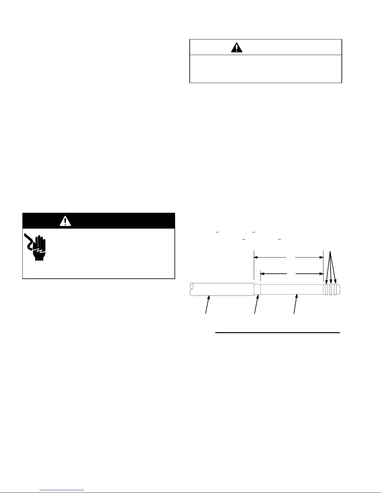
Graco Waterborne Fluid Hose (purchased
separately)
A Graco waterborne fluid hose must be used between
the voltage isolation system fluid outlet and the spray
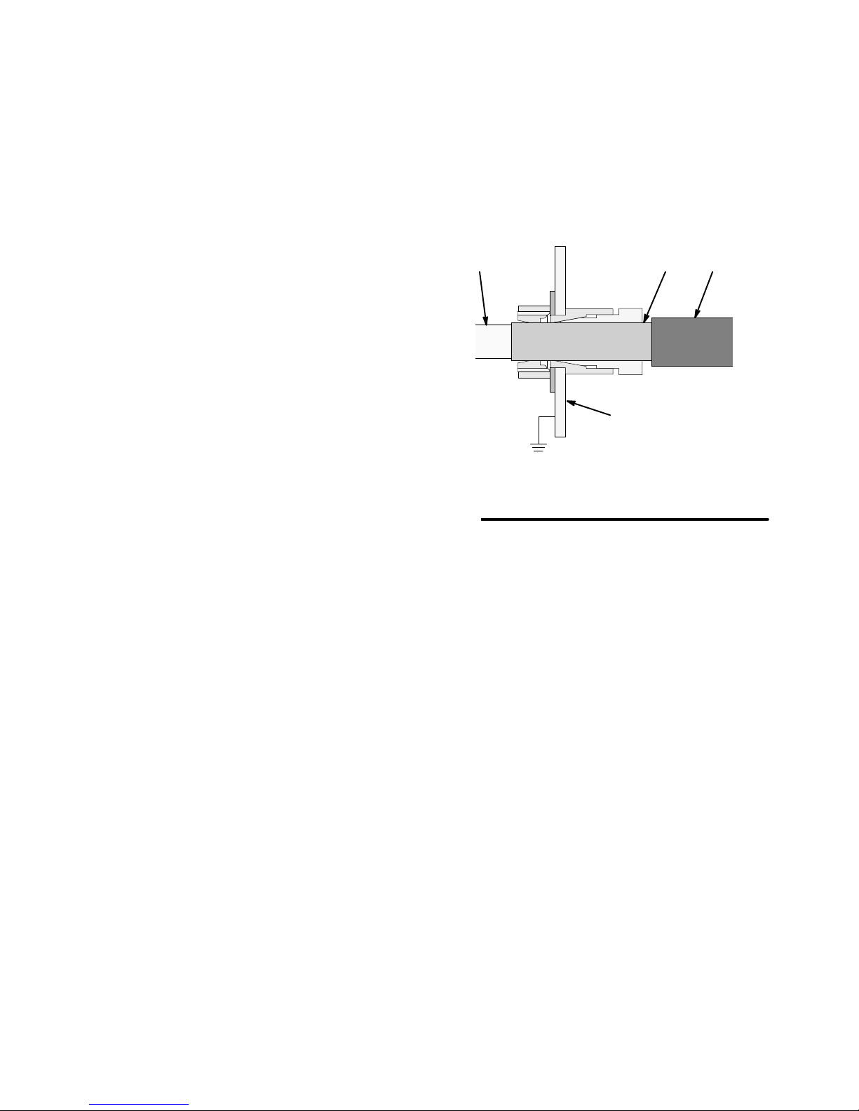
gun fluid inlet. This fluid hose consists of three layers
(see Fig. 2):
Inner Hose Layer (EE): is a PTFE tube.
Conductive Hose Layer (DD): covers the PTFE
tube.
Outer Hose Jacket (FF): is a protective polyethyl-
ene hose cover.
If a hose failure occurs, where the high voltage arcs
through the inner hose layer (EE), the voltage will be
discharged to ground through the conductive hose
layer (DD). When properly installed, the conductive
hose layer is grounded through its connection to the
grounded safety fence or enclosure (CC). All areas of
the fluid hose that are accessible to personnel must be
covered by the outer hose jacket (FF) to avoid electric
shock.
KEY-Fig. 2
DD Conductive Hose Layer
EE Inner Hose Layer
FF Outer Hose Jacket
CC Grounded Enclosure
The portion of the inner hose layer (EE–PTFE tube) that is not
covered by the conductive hose layer (DD), must be inside the
safety fence or enclosure (CC).
The areas of the waterbase fluid hose that are accessible to
personnel during normal operation must be covered by the outer
hose jacket (FF).
DDEE
FF
CC
H2O PRO Voltage Block connection shown
Fig. 2
05179
8 308584
Page 9
Installation
Installing the System
WARNING
ELECTRIC SHOCK HAZARD
Installing and servicing this equipment
requires access to parts which could
cause an electric shock or other serious
injury if the work is not performed properly.
Do not install or service this equipment unless
you are trained and qualified.
Comply with all local, state, and national codes
for the installation of electrical apparatus in a
Class I, Group D, Hazardous Location.
Comply with all applicable local, state, and
national fire, electrical, and other safety regulations.
Fig. 3, page 10, shows a typical Model PRO 3500wb
waterborne system. The particular type and size system for your operation must be custom designed for
your needs. For assistance in designing a system,
contact your Graco representative.
Accessories are available from your Graco representative. Refer to the Product Data Sheet for the gun,
Form No. 305681.
Basic Guidelines
When spraying waterborne fluids electrostatically:
The gun must be connected to a voltage isolation
system, which isolates the fluid supply from ground
and allows voltage to be maintained at the tip of the
gun.
All components of the isolation system that are
charged to high voltage must be contained within a
fence or enclosure that prohibits personnel from
making contact with the high voltage components.
The system should not have any severe arcing
occurring when the isolation mechanism opens and
closes. Severe arcing will shorten the life of the
system components.
Warning Signs
Mount the warning sign, part no. 186118, in the spray
area where it can easily be seen and read by all operators. Additional warning signs are available at no
charge.
Ventilate the Spray Booth
WARNING
TOXIC FLUID HAZARD
Provide fresh air ventilation to avoid the
buildup of toxic vapors. Do not operate
the gun unless the ventilating fans are
on.
Check and follow all local, state, and national codes
regarding air exhaust velocity requirements. High
velocity air exhaust will decrease the operating efficiency of the electrostatic system. The minimum
allowable air exhaust velocity is 60 linear feet/minute
(18.3 linear meters/minute).
308584 9
Page 10
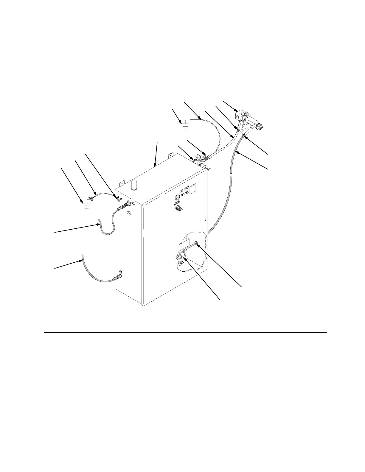
KEY-Fig. 3
A Air Regulator
B Spray Gun Air Shut-off Valve
C Gun Fluid Regulator
D Graco Waterborne Fluid Hose
E Gun Fluid Inlet
F PRO 3500wb Spray Gun
G Gun Air Inlet
H Graco Red Electrically Conductive Gun Air Hose
Installation
K Air Supply Hose
L Fluid Supply Hose
M Gun Air Hose Ground Wire
N True Earth Ground
P Fluid Hose Port
R H2O PRO Batch System Voltage Block Enclosure
S Main Ground Wire
T Ground Lug
PRO 3500wb Gun shown with the
Graco H2O PRO Batch System
Consult your isolation system
manual for other configurations.
T
S
N
K
L
M
N
R
H
B
F
G
A
E
D
Fig. 3
10 308584
P
C
05310
Page 11

Installation
Install the Air Line Accessories
1. Install an air line filter and an air and water separator on the main air supply line to ensure a dry,
clean air supply to the gun. Dirt and moisture can
ruin the appearance of your finished workpiece
and can cause the gun to malfunction.
2. Install a bleed-type air regulator (A) on the pump
and gun air supply lines to control air pressure to
the pump and gun. Refer to Fig. 3, page 10.
3. Install a bleed-type air shutoff valve on the main air
line, the pump air line (to shut off air to the pump),
and the gun air line (B) (to shut off air to the gun).
WARNING
PRESSURIZED EQUIPMENT HAZARD
Trapped air can cause the pump to cycle or the
gun to spray unexpectedly, which could result in a
serious injury, including splashing in the eyes or on
the skin. The bleed-type air shutoff valve is required on the main air supply line so trapped air will
be relieved between this valve and the pump after
the air regulator is closed.
Connect the red-colored Graco Electrically Conductive
Air Hose (H) to the gun air inlet and connect the hose
ground wire (M) to a true earth ground (N). Refer to
Fig. 3, page 10. Check the electrical grounding of the
gun as instructed on page 15. See page 48 to order
the air hose.
NOTE: The hose and the gun have special left-hand
threads to prevent connecting another type of air hose
to the gun air inlet.
Connect the Exhaust Tube
Press the exhaust tube (provided) onto the barbed
adapter on the bottom of the gun handle. Secure the
tube with the clamp provided. Refer to page 46.
Install the Fluid LIne Accessories
1. Before connecting the fluid line, blow it out with air
and flush it with water.
2. A fluid regulator (C) is needed in the fluid line to
control fluid pressure to the gun. Refer to Fig. 3,
page 10.
NOTE: The H2O PRO voltage block comes with a fluid
regulator already installed.
Connect the Air Line
WARNING
ELECTRIC SHOCK HAZARD
To reduce the risk of an electric shock or
other serious injury, you must use the
red-colored Graco Electrically Conductive Air Hose for the gun air supply hose, and you
must connect the hose ground wire to a true earth
ground. Do not use the black or grey-colored Graco
air hoses.
3. Install a fluid filter and drain valve at the pump
outlet.
WARNING
PRESSURIZED EQUIPMENT HAZARD
To reduce the risk of serious injury, including
splashing in the eyes or on the skin, install a fluid
drain valve close to the pump’s fluid outlet. The
fluid drain valve is required in your system to assist
in relieving fluid pressure in the displacement
pump, hose and gun; triggering the gun to relieve
pressure may not be sufficient.
308584 11
Page 12
Installation
Filter the Fluid
Filter the fluid to remove coarse particles and sediment
which could clog the fluid nozzle. The filter must be
installed at the grounded fluid inlet to the voltage
isolation system.
Connect the Fluid Hose
CAUTION
Be careful not to cut into the inner hose layer (K)
when stripping the hose. Nicks or cuts in the tube will
cause premature hose failure.
2. Inspect the condition of the o-rings (G) on the hose
barbed-fitting. Replace the o-rings if they are worn
or damaged.
NOTE:
A Graco waterborne fluid hose must be used
between the voltage isolation system fluid outlet
and the spray gun fluid inlet. See page 48 to order
the Graco waterborne fluid hoses and the hose
replacement parts.
Before connecting the fluid supply line to the gun,
blow it out with air, and flush it with water to remove
contaminants. Flush the gun before using it.
WARNING
ELECTRIC SHOCK HAZARD
To reduce the risk of an electric shock,
install only one continuous Graco water-
borne fluid hose between the isolated
fluid supply and the spray gun. Do not splice hoses
together.
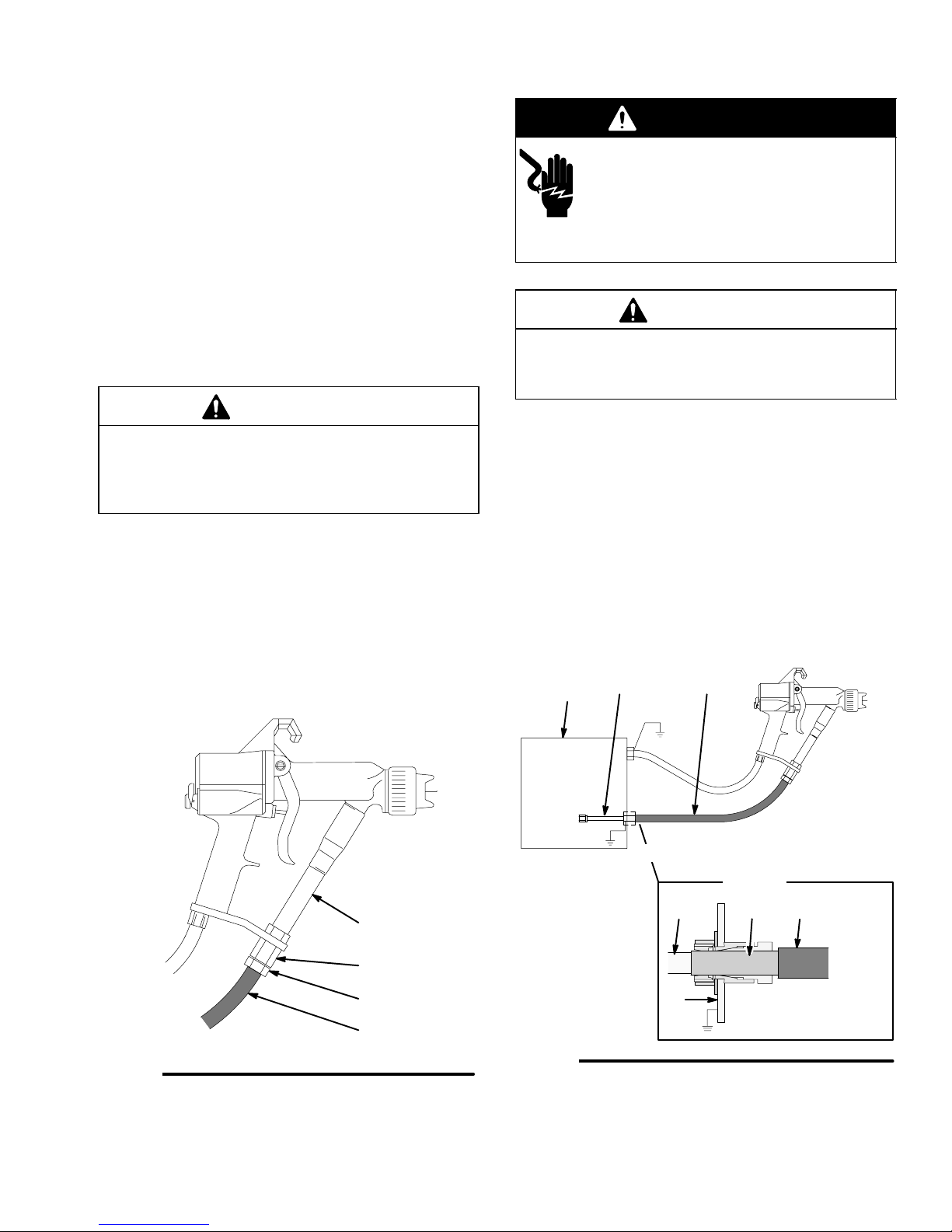
1. For the fluid hose to seal properly and be held
securely, the hose must be stripped and assembled to the dimensions shown in Fig. 4. Refer
also to Fig. 29, page 42. A new Graco waterborne
fluid hose comes fully assembled to the proper
dimensions.
3. Unscrew the hose ferrule housing (79) from the
gun fluid inlet fitting, and slide the nut onto the
barbed-end of the hose. Refer to Fig. 5.
4. Apply a light coat of dielectric grease (supplied
with the gun) to the o-rings (G) and to the entire
length of the inner hose layer (K). See Fig. 4.
KEY- Fig. 4
G O-Rings
H Outer Hose Jacket
J Conductive Hose Layer
K Inner Hose Layer
Apply a light coat of dielectric grease to the o-rings (G) and the
entire length of the inner hose layer (K)
4.075 + 0.10 in. (103.5 + 2.5 mm)
Minimum of 4.375 + 0.10 in. (111.1 + 2.5 mm)
G
Spray Gun
HJK
Fig. 4
Hose End
05342
12 308584
Continued on the next page
Page 13
Installation
Connect the Fluid Hose (continued)
5. Insert the hose (Y) into the hose ferrule housing
(79). See Fig. 5.
6. Push the hose firmly through the fluid inlet tube
(75) until the o-rings on the hose barbed fitting are
seated and the hose bottoms out.
7. Tighten the hose ferrule (77) firmly with a wrench
to about 50 in-lb (5.6 Nm). Pull back on the hose
to make sure it is secure. If not, disconnect the
hose and inspect it for damage. Check the hose
connection periodically for signs that the hose is
loosening.
CAUTION
If the hose comes loose from the fitting, fluid leakage
will occur. Make sure the hose ferrule (77) is tight
and that nothing will pull or catch on the hose during
operation.
8. Connect the other end of the hose to the isolated
fluid supply as instructed in the voltage isolation
system manual. See Fig. 6.
KEY- Fig. 5
Y Graco W aterborne Fluid Hose
75 Fluid Inlet Tube
77 Hose Ferrule
79 Hose Ferrule Housing
Torque to 50 in-lb (5.6 Nm)
WARNING
ELECTRIC SHOCK HAZARD
To reduce the risk of an electric shock,
the areas of the waterborne fluid hose
that are accessible to personnel during
normal operation must be covered by the outer
hose jacket (H). See Fig. 6.
CAUTION
The Graco warranty is void if the spray gun is connected to a non-Graco voltage isolation system or if
the gun is operated above 60 kV.
KEY- Fig. 6
H Outer Hose Jacket
K Inner Hose Layer
R Voltage Isolation System Enclosure
The areas of the waterborne fluid hose that are accessible to
personnel during normal operation must be covered by the outer
hose jacket (H).
The portion of the inner hose layer (K) that is not covered by
the outer hose jacket (H) must be inside the voltage isolation
system enclosure (R).
The conductive hose layer (J) must be grounded through its
connection to the isolation system’s grounded safety fence or
enclosure (R).
R
KH
Fig. 5
75
79
77
Y
05405B
Fig. 6
DETAIL
J
R
H2O PRO Voltage Block
connection shown
HK
05149B
308584 13
Page 14
Installation
Ground the System
WARNING
FIRE, EXPLOSION, AND
ELECTRIC SHOCK HAZARD
When operating the electrostatic device,
any ungrounded objects in the spray
area (such as people, containers, tools,
etc.) can become electrically charged.
Improper grounding can result in static
sparking, which can cause a fire, explosion, or electric shock. Follow the
grounding instructions below.
The following grounding instructions are minimum requirements for a basic electrostatic, waterborne
system. Your system may include other equipment or
objects which must be grounded. Check your local
electrical code for detailed grounding instructions. Your
system must be connected to a true earth ground.
1. Fluid Supply: Ground the fluid supply by connecting a ground wire and clamp between the fluid
supply and a true earth ground. See your fluid
supply instruction manual for grounding instructions.
2. PRO 3500wb Electrostatic Air Spray Gun:
Install the red-colored Graco electrically conductive air hose between the gun and air supply line
and connect the air hose ground wire to a true
earth ground. Check the electrical grounding of the
gun as instructed on page 15.
3. Graco Waterborne Fluid Hose: The conductive
layer of the hose must be properly grounded by
correct installation as instructed on pages 12 to 13.
4. Voltage Isolation System: Ground the system
according to the manufacturer’s instructions.
5. All persons entering the spray area: Their
shoes must have conductive soles, such as
leather, or personal grounding straps must be
worn. Rubber or plastic soles are not conductive.
The operator must not wear gloves which insulate
the hand from the spray gun. The gloves must be
conductive or modified as shown on page 17.
6. Object being sprayed: Keep the workpiece
hangers clean and grounded at all times. Contact
points must be sharp points or knife edges.
7. The floor of the spray area: The floor must be
electrically conductive and grounded. Do not cover
the floor with cardboard or any non-conductive
material which would interrupt grounding continuity.
8. All electrically conductive objects or devices
in the spray area: They must be properly
grounded.
14 308584
Page 15
Installation
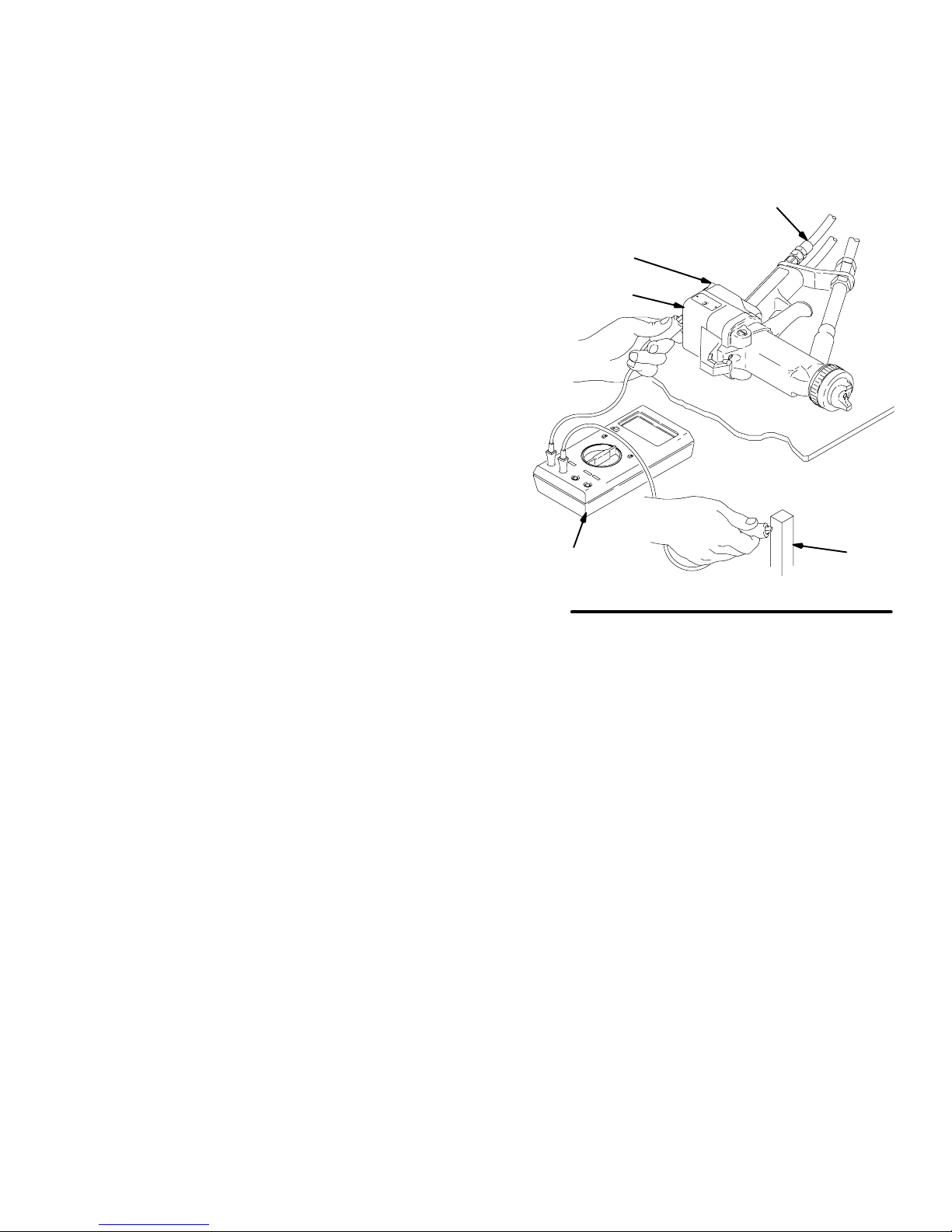
Check the Electrical Grounding
1. Have a qualified electrician check the electrical
grounding continuity of the spray gun and air hose.
2. Make sure the red Graco electrically conductive air
hose (EE) is connected to the gun and the hose
ground wire is connected to a true earth ground.
See Fig. 7.
3. The air and fluid supplies to the fluid hose must be
turned off and the fluid hose must not have any
fluid in it when checking the continuity.
4. Turn the gun ES ON-OFF lever (DD) to OFF.
5. Measure the resistance between the gun handle
(AA) and a true earth ground (BB) with an ohmmeter (CC). Resistance should not exceed 100 ohms.
6. If the resistance is greater than 100 ohms, check
the tightness of the ground connections, and be
sure the air hose ground wire is connected to a
true earth ground. If the resistance is still too high,
replace the air hose.
KEY- Fig. 7
AA Gun Handle
BB True Earth Ground
CC Ohmmeter
DD ES ON-OFF Lever
EE Graco Electrically Conductive Air Hose
DD
AA
CC
Fig. 7
EE
BB
05150B
308584 15
Page 16
Operation
Fluid Voltage Discharge and Grounding
Procedure
WARNING
ELECTRIC SHOCK HAZARD
The high voltage fluid supply is charged
with high voltage until the voltage is dis-
charged. Contact with the charged components of the isolation system or spray gun electrode will cause an electric shock. To avoid an electric shock, follow the Fluid Voltage Discharge
and Grounding Procedure:
when instructed to discharge the voltage,
before cleaning, flushing, or servicing the sys-
tem equipment,
before approaching the front of the gun,
and before opening the safety fence or the
enclosure for the isolated fluid supply.
NOTE: An accessory grounding rod, part no. 210084,
is available to discharge any voltage remaining on a
system component. Contact your Graco representative
to order it.
1. Turn off the gun electrostatics by turning the gun
ES ON-OFF lever to the OFF position.
Pressure Relief Procedure
WARNING
PRESSURIZED EQUIPMENT HAZARD
The system pressure must be manually relieved to
prevent the system from starting or spraying accidentally. To reduce the risk of an injury from accidental spray from the gun, splashing fluid, or
moving parts, follow the Pressure Relief Proce-
dure whenever you:
are instructed to relieve the pressure,
stop spraying,
check or service any of the system equipment,
or install or clean the fluid nozzle.
1. Follow the Fluid Voltage Discharge and
Grounding Procedure, at left.
2. Relieve fluid pressure in the fluid supply and
voltage isolation system as instructed in their
instruction manuals.
2. Discharge the voltage at the voltage isolation
system by following the procedure specified in the
voltage isolation system instruction manual.
3. Touch the electrode of the gun with a grounded rod
to make sure that the voltage has been discharged. If an arc is seen, verify that the electrostatics are turned off or see Troubleshooting,
page 24, or the voltage isolation system manual
for other possible problems. Resolve the problem
before proceeding.
3. Turn off the fluid supply to the gun.
4. Shut off the air supply to the spray gun. The
shut-off device must bleed the air out of the system.
5. Trigger the gun into a grounded metal waste
container to relieve fluid pressure.
16 308584
Page 17

Operation
Operating Checklist
Check the following list daily, before starting to operate
the system, to help ensure safe, efficient operation.
____ 1. All the operators are properly trained to safely
operate an electrostatic, waterborne, air spray
system as instructed in this manual and the
voltage isolation system manual.
____ 2. All the operators are trained how to properly
relieve system pressure as instructed on page
16.
____ 3. All the operators are trained how to properly
discharge the voltage as instructed on page
16.
____ 4. The operator is not wearing gloves which
insulate the hand from the spray gun. If worn,
gloves must be conductive or modified as
shown in Fig. 8 so as not to interfere with the
operator grounding through the gun.
____ 5. The system is thoroughly grounded and the
operator and all persons entering the spray
area are properly grounded. See Ground the
System, page 14, and Check the Electrical
Grounding, page 15.
____ 6. The condition of the electrical components of
the spray gun has been checked as instructed
in Electrical Tests, page 28.
____ 7. All fluid hose connections are tight.
____ 8. The ventilation fans are operating properly.
____ 9. All the debris, including flammable liquids and
rags, is removed from the spray area.
3 in. (76 mm) square cut out and
finger of glove cut off
NOTE: If gloves are worn, they must be conductive or
modified as shown so they do not interfere with operator
grounding through the gun.
Fig. 8
Selecting a Fluid Nozzle and Air Cap
The gun is supplied with a 0.06 inch (1.5 mm) fluid
nozzle, part no. 191833, and an air cap, part no.
193033. If your application requires a different nozzle
and air cap combination, see instruction manual
307803 or consult your authorized Graco distributor to
select the appropriate fluid nozzle and air cap. Install
the air cap and fluid nozzle as instructed on page 30.
308584 17
Page 18

Operation
Operating the Spray Gun
WARNING
FIRE AND EXPLOSION HAZARD
To reduce the risk of fire and explosion,
only use this equipment to spray nonflammable, waterborne fluids as defined
on the front cover of this manual.
WARNING
ELECTRIC SHOCK HAZARD
Contact with the charged components of
the spray gun will cause an electric
shock. Do not touch the gun nozzle or
electrode or come within 4 inches (101.6 mm) of
the front of the gun during gun operation or until
after following the Fluid Voltage Discharge and
Grounding Procedure on page 16.
Follow the Fluid Voltage Discharge and Ground-
ing Procedure on page 16 when you stop spraying and whenever you are instructed to discharge
the voltage.
WARNING
1. Follow the Operating Checklist on page 17.
2. Make sure the system voltage is discharged.
Loosen the air cap retaining nut, and rotate the air
cap for a vertical or horizontal spray pattern. See
Fig. 9. Then tighten the retaining nut until the air
cap is held firmly in place; you should not be able
to rotate the air cap horns by hand.
Vertical Pattern
Horizontal Pattern
Fig. 9
3. Pressurize the fluid supply, and adjust the fluid
flow by using the fluid pressure regulator installed
in the fluid line. Refer to instruction manual 307803
to set the fluid pressure for various fluid flows,
according to the size of the fluid nozzle being
used.
02020
PRESSURIZED EQUIPMENT HAZARD
To reduce the risk of an injury, follow the Pressure
Relief Procedure on page 16 when you stop
spraying, before installing or cleaning the fluid
nozzle, and whenever you are instructed to relieve
the pressure.
WARNING
COMPONENT RUPTURE HAZARD
To reduce the risk of component rupture,
which can cause serious injury, do not
exceed the maximum working pressure
of the lowest rated system component. This equipment has a 100 psi (0.7 MPa, 7 bar) maximum
working air and fluid pressure.
Follow the steps below to establish the correct fluid
flow and air flow. Do not turn the ES ON-OFF lever to
ON yet:
4. If necessary, further adjust the fluid flow rate with
the fluid adjustment knob (J). See Fig. 10.
5. Fully open the fan air valve (P).
6. Set the air pressure with the air pressure regulator.
The following chart shows the air hose inlet pressure required to get full voltage from the power
supply. To avoid shortening the turbine life, do not
exceed the recommended air pressures.
Air Hose
Length
ft. (m)
15 (4.6) 45 to 50 (314 to 345, 3.1 to 3.4)
25 (7.6) 50 to 55 (345 to 379, 3.4 to 3.7)
50 (15.3) 60 to 65 (410 to 444, 4.1 to 4.4)
75 (22.9) 68 to 73 (465 to 501, 4.5 to 5.0)
100 (30.5) 75 to 80 (514 to 550, 5.1 to 5.5)
Dynamic pressure at air hose inlet
required for full voltage
psi (kPa, bar)
18 308584
Page 19

Operation
7. Set the atomizing air valve (R) about 1.5 turns out
for most applications. The Atomizing Air Valve
Adjustment chart shows the effect of the atomizing air valve adjustment on the air cap air flow.
8. Adjust the pattern width with the fan air valve (P).
Atomizing Air Valve Adjustment
100
90
80
70
60
50
40
30
20
Air Cap Air Flow (%)
10
0
0.00 0.50 1.00 1.50 2.00 2.50 3.00
Fully Open Fully Closed
Valve Turns
11. Use the same spraying technique you would use
with a conventional air spray system to coat the
workpiece.
12. Relieve the pressure and discharge the voltage
when you stop spraying.
CAUTION
Hang the gun with its nozzle pointing down when it is
not being used to avoid having fluid run into the gun
air passages. See Fig. 11. Fluid in the gun air passages can cause poor atomization and excessive
current demands and damage the gun.
KEY-Fig. 10
J Fluid Adjustment Knob
M ES Indicator Light
N ES ON-OFF Lever
P Fan Air Adjustment Valve
R Atomizing Air Valve
M
Fine Adjustments of the Spray Gun
To improve the atomization, open the atomizing air
valve further (R). If more atomizing air is needed
beyond the fully open position of the valve, increase
the air hose inlet pressure.
Use the lowest air flow settings needed for acceptable atomization. The slower particle velocity will
improve the electrostatic effect.
To reduce the atomization air and minimize any
overspray, turn the atomizing air valve in.
9. Turn the ES ON-OFF lever (N) to ON to begin
spraying with the electrostatics. When spraying,
the ES indicator light (M) should glow, indicating
the electrostatic charge.
NOTE: See Spray Pattern Troubleshooting on page
25 to correct spray pattern problems. See Voltage
Loss Troubleshooting on page 22 to correct voltage
problems.
Fig. 10
J
P*N R
05151A
10. Operate the voltage isolation system as instructed
in the system manual. Normal spraying voltage for
the system will be 45 to 55 kV.
Fig. 11
05424
308584 19
Page 20

Operation
Shutdown
WARNING
PRESSURIZED EQUIPMENT HAZARD
To reduce the risk of an injury, follow the Pressure
Relief Procedure on page 16 whenever you stop
spraying and whenever you are instructed to
relieve pressure.
Maintenance
WARNING
FIRE AND EXPLOSION HAZARD
To reduce the risk of fire and explosion:
Only flush, purge, or clean the PRO
3500wb spray gun with non-flammable fluids, as defined on the front
cover of this manual.
Do not flush with the gun electrostatics turned
on.
WARNING
ELECTRIC SHOCK HAZARD
Follow the Fluid Voltage Discharge
and Grounding Procedure on page 16
before cleaning or flushing the gun to
ensure the voltage is discharged and avoid serious
injury from an electric shock.
1. Relieve the pressure.
2. Flush and clean the equipment. Follow the instruction in Maintenance.
Daily Care and Cleaning
CAUTION
Fluid left in gun air passages could result in a poor
quality paint finish and may draw current and reduce
the electrostatic effect. Fluid in the power supply
cavity can reduce the alternator life.
Immersing the gun in fluid is not recom-
mended.
Do not use any cleaning method which may
allow solvent into the gun air passages.
Point the gun down while cleaning to prevent
fluid from running into the air passages. See
Fig. 12.
Hang the gun with its nozzle pointing down
when it is not being used.
1. Clean the fluid and air line filters daily.
2. Clean the outside of the gun daily with a soft cloth
dampened in a non-flammable cleaning fluid.
WARNING
PRESSURIZED EQUIPMENT HAZARD
To reduce the risk of an injury, follow the Pressure
Relief Procedure on page 16 when you stop
spraying, before cleaning or flushing the spray gun,
and whenever you are instructed to relieve the
pressure.
20 308584
3. Clean the air cap and fluid nozzle daily, minimum,
as instructed on page 21. Some applications
require more frequent cleaning. Replace the fluid
nozzle and air cap if they are damaged. See page
30.
4. Check the electrode wire. Straighten it if it is bent,
and replace it if it is broken or damaged. See page
32.
5. Check for any fluid leakage from the gun and fluid
hoses. Tighten fittings or replace equipment as
needed.
6. Check all of the work hangers for build-up of
material; clean them if necessary.
7. Flush the gun before changing colors and whenever you are done operating the gun. See page 21.
Page 21

Maintenance
Clean the Air Cap and Fluid Nozzle
Equipment needed:
Soft bristle brush
Non-flammable cleaning fluid
CAUTION
Do not use metal tools to clean the air cap or fluid
nozzle holes as this could scratch them, and make
sure the electrode wire is not damaged. Scratches in
the air cap or nozzle or a damaged electrode wire
can distort the spray pattern.
Procedure:
1. Relieve the pressure and discharge the system
voltage as instructed on page 16.
2. Remove the air cap retaining nut and air cap.
3. Clean the air cap with the soft bristle brush and a
non-flammable cleaning fluid or submerge the air
cap in the cleaning fluid and wipe it clean.
Flush the Spray Gun
1. Relieve the pressure and discharge the system
voltage as instructed on page 16.
2. Make sure the gun ES ON-OFF lever is turned to
OFF.
3. Turn off the air to the spray gun.
4. Change the fluid supply over to the cleaning fluid.
Read the voltage isolation system manual for
specific flushing procedures.
5. Spray the cleaning fluid until the fluid that comes
out of the gun is clear.
6. Shut off the fluid supply and relieve the pressure
as instructed on page 16.
7. Before spraying paint again, reconnect the paint
supply, turn on the fluid and air supplies, and
trigger the gun until it is clear of cleaning fluid.
4. With the front of the gun pointed down, clean the
fluid nozzle and the front of the gun with the soft
bristle brush and cleaning fluid. See Fig. 12.
NOTE: If it appears that there is fluid inside the fluid
nozzle air passages, remove the gun from the line for
servicing.
5. Clean the exterior of the gun with a cloth dampened in a non-flammable cleaning fluid.
6. Carefully install the air cap. Be sure to insert the
electrode wire through the center air cap hole and
do not bend the wire. Rotate the air cap horns to
the desired position.
7. Tighten the retaining nut until the air cap is held
firmly in place; you should not be able to rotate the
air cap horns by hand.
8. Test the gun resistance as instructed on page 28.
05152A
Fig. 12
308584 21
Page 22

Troubleshooting
WARNING
ELECTRIC SHOCK HAZARD
Installing and servicing this equipment
requires access to parts which may
cause an electric shock or other serious
injury if the work is not performed properly. Do not
install or service this equipment unless you are
trained and qualified.
Follow the Fluid Voltage Discharge and Ground-
ing Procedure on page 16 before checking or
servicing the system and whenever you are
instructed to discharge the voltage to ensure the
voltage is discharged and avoid serious injury from
an electric shock.
WARNING
PRESSURIZED EQUIPMENT HAZARD
To reduce the risk of an injury, follow the Pressure
Relief Procedure on page 16 before checking or
servicing any part of the system and whenever you
are instructed to relieve the pressure.
Voltage Loss Troubleshooting
Normal spraying voltage for a system using the PRO
3500wb gun is 45 to 55 kV. The system voltage is
lower due to spraying current demands and voltage
isolation system losses.
A loss of spraying voltage can be caused by a problem
with the spray gun, fluid hose, or voltage block, since
all of the system components are electrically connected through the conductive, waterborne fluid.
Before troubleshooting or servicing the voltage block
itself, you need to determine which component in the
system is most likely causing a problem. Possible
causes include:
Spray Gun
Fluid leakage
Dielectric breakdown at the fluid hose connection or
fluid packings
Not enough air pressure for the turbine
Faulty power supply
Excessive overspray on gun surfaces
Fluid in the air passages
Waterborne Fluid Hose
Dielectric failure of hose (pin-hole leak through
PTFE layer)
Air gap in the fluid column between the gun and
isolated fluid supply, causing a low voltage reading
on the isolation system voltage meter.
Voltage Block
Fluid leakage
Dielectric breakdown of hoses, seals, or connec-
tions
Isolators not functioning properly
Visual Check
First, check the system for any visible faults or errors
to help isolate whether the spray gun, fluid hose or
voltage block has failed. A voltage probe and meter,
part no. 236003, is helpful for diagnosing voltage
problems and is required for some of the troubleshooting tests that follow.
1. Check that all of the air and fluid tubes and hoses
are properly connected.
2. Check that the voltage isolation system valves and
controls are properly set for operation. Refer to the
voltage isolation system manual.
3. Check that the spray gun and voltage isolation
system have sufficient air pressure.
4. Check that the gun ES ON-OFF lever is in the ON
position and that the gun ES indicator light comes
on. If the ES indicator light does not come on,
remove the spray gun for service, and complete
the electrical tests on page 28.
5. Check that the voltage isolation system’s enclo-
sure door or safety fence gate is closed and that
any safety interlocks are engaged and working
properly.
6. Make sure the voltage isolation system is in the
“isolate” mode, where it is isolating the fluid voltage from ground.
22 308584
Page 23

Troubleshooting
Voltage Loss Troubleshooting (continued)
7. To eliminate air gaps in the fluid column, spray
enough fluid to purge the air out between the
voltage isolation system and the spray gun. An air
gap in the fluid hose can break the electrical
continuity between the spray gun and the isolated
fluid supply and cause a low voltage reading on a
voltage meter connected to the isolated fluid
supply.
8. Check the spray gun cover and barrel for accumulated overspray. Excessive overspray can create a
conductive path back to the grounded gun handle.
Install a new gun cover and clean the exterior of
the gun.
9. Inspect the entire system for any visible fluid
leakage and repair any fluid leaks that are found.
Pay special attention to the following areas:
Packing area of the spray gun
Fluid hose: check for leakage or any bulges in the
outer jacket, which may indicate an internal leak
Internal voltage isolation system components
Tests
If you still have no voltage, separate the spray gun and
hose from the voltage isolation system and check
whether the gun and hose alone will hold voltage with
the following test.
1. Flush the system with water and leave the lines
filled with water.
4. Position the end of the hose as far as possible
away from any grounded surface. The end of the
hose must be at least 1 ft. (305 mm) from any
ground. Make sure that no one is within 3 ft. (914
mm) of the end of the hose.
5. Turn the ES ON-OFF valve to ON, and trigger the
gun just enough to turn on the air to the gun but
not the fluid. Measure the voltage at the gun
electrode with a voltage probe and meter.
6. Discharge the system voltage by waiting 30 seconds and then touching the gun electrode with a
grounded rod.
7. If the meter reading is 45 to 55 kV, the gun and
fluid hose are okay, and the problem is in the
voltage isolation system. See the voltage isolation
system manual for further troubleshooting
information.
If the reading is below 45 kV, the problem is in the
gun or fluid hose.
8. Flush the fluid hose and gun with enough air to dry
out the fluid passages.
9. Turn the ES ON-OFF valve to ON, and trigger the
gun. Measure the voltage at the gun electrode with
a voltage probe and meter.
2. Relieve the pressure and discharge the system
voltage as instructed on page 16.
3. Disconnect the fluid hose from the voltage isolation
system.
NOTE: Avoid allowing any water to leak out of the fluid
hose as that could cause a significant air gap in the
fluid column up to the gun electrode, which can break
the conductivity path and conceal a potential failure
area.
10. If the meter reading is 55 to 60 kV, the gun power
supply is okay, and there is probably a dielectric
breakdown somewhere in the fluid hose or gun.
Continue with step 11.
If the reading is below 55 kV range, do the
electrical tests on page 28 to check the gun and
power supply resistance. If those tests show the
gun and power supply are okay, continue with step
11, page 24.
308584 23
Page 24

Troubleshooting
Voltage Loss Troubleshooting (continued)
11. A dielectric breakdown is most likely in one of the
following three areas. Repair or replace the component that is failing.
Fluid hose
Check for leakage or any bulges in the outer
jacket, which may indicate a pin-hole leak
through the PTFE layer. Disconnect the fluid
hose from the gun, and look for signs of fluid
contamination on the outside of the PTFE
portion of the fluid tube.
Inspect the end of the hose connected to the
voltage block. Look for cuts or nicks.
Make sure the hose is properly stripped; see
Fig. 4, page 12, for hose stripping dimensions.
Restrip or replace the hose.
Fluid packings
Remove the packing assembly from the gun
as instructed on page 33, and look for signs of
fluid leakage or any blackened areas, which
would indicate arcing is occurring along the
packing rod.
Fluid hose connection joint to the spray gun
A breakdown at the fluid hose connection joint
would be caused by fluid leaking past the
o-ring seals on the end of the hose. Remove
the hose at the gun connection and look for
signs of fluid leakage along the PTFE tube.
12. Before reassembling the gun, clean and dry the
gun fluid inlet tube (item 75 on page 46). Repack
the inner spacer of the fluid packing rod with
dielectric grease and reassemble the gun as
instructed on page 34.
13. Reconnect the fluid hose as instructed on page 12.
14. Check the gun voltage with the voltage probe and
meter before filling the gun with fluid.
Electrical Troubleshooting
Problem Cause Solution
Voltage is still present at the gun
after following the Fluid Voltage
Discharge and Grounding Procedure
The operator gets a shock The operator is not properly grounded
The operator gets a shock when
touching the workpiece
Gun electrostatics (gun ES lever) are
not turned off.
Did not wait long enough for the voltage to discharge through the voltage
bleed resistor.
There is an air pocket in the fluid line
that leaves the fluid near the gun
isolated.
Voltage isolation system failed. See the isolation system manual for
or is near an ungrounded object.
The gun is not properly grounded. See Check the Electrical Ground-
The workpiece is not properly
grounded.
Turn off the gun electrostatics.
Wait a longer period of time before
touching the electrode with a
grounded rod. Check for possible
bleed resistor failure.
Determine the cause of the air pocket
and fix the problem. Purge the air out
of the fluid line.
service information.
Be sure the floor and the operator are
properly grounded; see Ground the
System, page 14.
ing, page 15.
Clean the workpiece hangers; check
for proper grounding on the conveyor
or track
24 308584
Page 25

Troubleshooting
Spray Pattern Troubleshooting
NOTE: Some spray pattern problems are caused by the improper balance between air and fluid.
Problem Cause Solution
Fluttering or spitting spray
Improper spray pattern
The fluid supply is insufficient. Adjust the fluid regulator, or fill the
fluid supply.
The fluid nozzle is loose, or the fluid
nozzle taper seat is damaged.
There is dirt between the fluid nozzle,
taper seat, and gun body.
The coupler at the fluid inlet is loose
or cracked.
There is fluid build-up on the air cap;
partially clogged horn holes; or full air
pressure from the clean horn hole
forces the fan pattern toward the
clogged end.
The electrode is bent. Straighten the electrode.
The fluid nozzle or air cap holes are
damaged.
There is fluid buildup on the perimeter
of the fluid nozzle orifice, or a partially
clogged fluid nozzle orifice.
The electrode is bent. Straighten the electrode wire.
The fan air pressure is too high. Reduce the fan air pressure.
Tighten or replace the fluid nozzle;
see page 30.
Clean the parts; see page 21.
Tighten or repair the coupler.
Clean the air cap with a soft implement or submerge it in water and
wipe it clean; see page 21.
Replace the damaged part; see page
30.
Remove the obstruction; never use
wire or hard instruments; see page
21.
Streaks
The fluid is too thin. Reduce the fluid viscosity.
There is not enough fluid pressure. Increase the fluid pressure.
The fan air pressure is too low. Increase the fan air pressure.
The fluid is too thick. Reduce the fluid viscosity.
There is too much fluid. Reduce the fluid flow.
The last coat of fluid is applied too
wet.
There is too much air pressure. Decrease the air pressure.
The air pressure is insufficient. Increase the air pressure.
The spray pattern is non-uniform. Clean or replace the air cap; see
Apply a drier finish using multiple
strokes.
page 21.
308584 25
Page 26

Troubleshooting
Poor Electrostatic Wrap Troubleshooting
Problem Cause Solution
The system is holding voltage but
there is poor electrostatic wrap on
the part being sprayed
The distance between the gun and
workpiece is incorrect.
The parts are poorly grounded. Clean the workpiece hangers; check
Booth exhaust velocity is too high. Reduce the exhaust velocity within
The atomizing air pressure is too
high.
The fluid pressure is too high. Reduce the fluid pressure.
The fluid viscosity is not right for
electrostatic spray.
Gun Operation Troubleshooting
Problem Cause Solution
Fluid leakage from the fluid packing area
Air leakage from the front of the
gun
Fluid leakage from the front of the
gun
“Orange Peel” finish
The fluid rod packings or fluid rod are
worn.
The packing nut is loose Tighten the packing nut; see page 33.
The air valve is not seating properly. Clean and service the air valve; see
The air valve o-ring is sticking. Lubricate the o-ring; see page 36.
The fluid rod is worn or damaged. Replace the fluid rod; see page 33.
The fluid seat is worn. Replace the fluid nozzle and/or elec-
The fluid packing is too tight. Lubricate and adjust the packing nut;
The resistor stud is loose. Tighten the resistor stud; see page
The fluid nozzle is loose. Tighten the fluid nozzle; see page 30.
The resistor stud o-ring is damaged. Replace the o-ring; see page 30.
The air pressure is insufficient for
good atomization.
The fluid is poorly mixed or filtered. Remix or refilter the fluid.
An improper thinner is being used. Use the proper thinner.
Adjust the spraying distance to 8 to
12 inches (203 to 305 mm).
for proper grounding on the conveyor
or track.
the code limits.
Reduce the atomizing air pressure.
Check with the supplier for proper
fluid viscosity for electrostatic spray.
Replace the packings or rod; see
page 33.
page 36.
trode needle; see pages 30 to 32.
see page 33.
30.
Increase the air cap air pressure by
opening the atomizing air valve more
or increasing the gun air inlet pressure; use the least air pressure needed for good results.
26 308584
Page 27
Troubleshooting
Gun Operation Troubleshooting (continued)
Excessive spray fog
No fluid sprays from the gun
The equipment is covered with
fluid
Dirty air cap
The air pressure is too high. Reduce the air cap air pressure by
closing the atomizing air valve more
or decreasing the gun air inlet pressure; use the least air pressure
needed for good results. Do not reduce below minimum pressure need-
ed for full voltage. See page 18.
The fluid is thinned too much. Properly thin the fluid.
The fluid supply is low. Check the fluid supply; add fluid if
necessary.
The fluid nozzle is dirty or clogged. Clean the fluid nozzle; see page 21.
The fluid nozzle is damaged. Replace the fluid nozzle; see page
30.
The exhaust air flow is insufficient or
not directed properly.
The distance between the gun and
workpiece is incorrect.
The electrode is bent. Straighten the electrode.
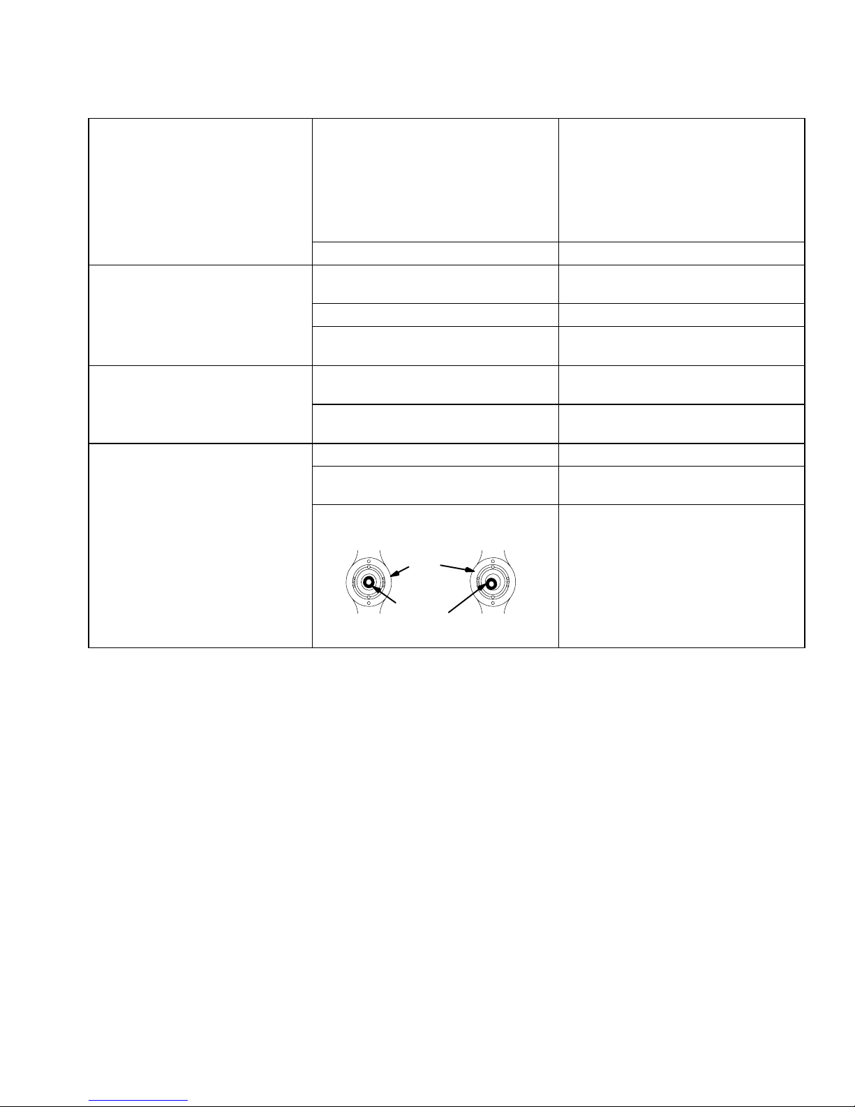
The nozzle orifice is damaged. Replace the fluid nozzle; see page
The air cap and fluid nozzle are misaligned.
Air
Cap
Check for the proper CFM; check the
baffles and direction of the air flow.
Adjust the spraying distance to 8 to
12 inches (203 to 305 mm).
30.
Check the air cap and fluid nozzle
seat for fluid buildup. Clean or
replace parts as needed; see page 21
or 30.
ALIGNED
Fluid
Nozzle
MISALIGNED
308584 27
Page 28

Electrical Tests
WARNING
ELECTRIC SHOCK HAZARD
Follow the Fluid Voltage Discharge
and Grounding Procedure on page 16
before checking or servicing and whenever you are instructed to discharge the voltage to
ensure the voltage is discharged and avoid serious
injury from an electric shock.
Use the megohmmeter (A), part no. 218979, and an
applied voltage of 500 volts to complete these
electrical tests. Connect the leads as shown.
Test Gun Resistance
NOTE: The fluid passage must be flushed and dried
to get an accurate reading. Check the resistance with
the gun triggered and untriggered.
1. Prepare the gun for service as instructed on
page 30.
WARNING
PRESSURIZED EQUIPMENT HAZARD
To reduce the risk of an injury, follow the Pressure
Relief Procedure on page 16 before checking or
servicing the gun and whenever you are instructed
to relieve the pressure.
WARNING
FIRE, EXPLOSION, AND
ELECTRIC SHOCK HAZARD
Megohmmeter P/N 218979 (A-see Fig.
13) is not approved for use in a hazardous area. To reduce the risk of sparking,
do not use the megohmmeter to do
electrical tests unless:
The gun has been removed from the
hazardous area;
Or all spraying devices in the hazardous area
are turned off, ventilation fans in the hazardous
area are operating, and there are no flammable
vapors in the area (such as open solvent containers or fumes from spraying).
2. Measure the resistance between the end of the
gun electrode (20) and the air inlet fitting (17). See
Fig. 13.
3. The resistance should be between 180 to 220
megohms. If the resistance is outside the specified
range, go to the next test.
4. If you still have problems, refer to Voltage Loss
Troubleshooting, page 22, for other possible
causes of poor performance, or contact the nearest authorized service agency.
KEY-Fig. 13
A Megohmmeter
17 Air Inlet Fitting
20 Electrode
A
Failure to follow this warning could cause fire,
explosion, electric shock and result in serious injury
and property damage.
The performance and safety of the spray gun are
directly affected by the condition of the electrical
components contained inside the gun. The electrical
tests can be used to determine the condition of the
power supply (18) and the resistor stud (22) as well as
the continuity of the electrical path between the components.
28 308584
20
Fig. 13
17
5153B
Continued on the next page.
Page 29

Electrical Tests
Test Power Supply Resistance
1. Prepare the gun for service as instructed on
page 30.
2. Remove the power supply (18) from the gun
handle as instructed on page 40.
3. Remove the turbine alternator (37) from the power
supply as instructed on page 41.
4. Measure the resistance from the power supply’s
ground contact point (B) to the contact spring (18c)
on the other end of the power supply. See Fig. 14.
5. The resistance should be 157.5 to 192.5
megohms. If the resistance is outside the specified
range, the power supply is defective and must be
replaced. If the resistance of the power supply is
correct, proceed to the next test.
KEY-Fig. 14
A Megohmmeter
B Ground Contact Point
18 Power Supply
18c Contact Spring
A
Test Resistor Stud Resistance
1. Prepare the gun for service as instructed on
page 30.
2. Remove the resistor stud (22) as instructed on
page 30.
3. Check the resistance between the black resistor
stud contact ring (D) and the needle contact ring
(C). See Fig. 15. You may have to press down on
the contact ring (D) in several places to get a good
reading.
4. The resistance should be 21 to 29 megohms. If the
resistance is correct, make sure the metal contact
in the gun barrel and the needle contact ring (C)
are clean. If the resistance is outside the specified
range, the resistor is defective and the resistor
stud (22) must be replaced. See page 30 to replace the resistor stud.
WARNING
FIRE, EXPLOSION, AND ELECTRIC
SHOCK HAZARD
The resistor stud contact ring (D) is a
conductive contact ring, not a sealing
o-ring. See Fig. 15. To reduce the risk of
sparking, which could cause a sparking
or electric shock, do not remove the
resistor stud contact ring (D) or operate
the gun without the contact ring in place.
Do not replace the resistor stud (22) with
anything but a genuine Graco part.
18c 18
Fig. 14
KEY-Fig. 15
C Needle Contact Ring
D Resistor Stud Contact Ring
22 Resistor Stud
22
B
D
03566
Fig. 15
C
0442
308584 29
Page 30

Tools Included with the Gun
Multi-tool
Ball-end Wrench
2 mm Hex Key Allen Wrench
Prepare the Gun for Service
Service
WARNING
PRESSURIZED EQUIPMENT HAZARD
To reduce the risk of an injury, follow the Pressure
Relief Procedure on page 16 before checking or
servicing any part of the system and whenever you
are instructed to relieve the pressure.
NOTE:
Check all the possible remedies in Troubleshoot-
ing before disassembling the gun.
If the plastic parts of the gun must be held in a vise,
use padded vise jaws to avoid damaging parts.
Lightly lubricate o-rings and seals with petroleum
jelly. Do not over-lubricate.
Only use genuine Graco parts. Do not mix or use
parts from other PRO Gun models.
WARNING
FIRE, EXPLOSION, AND ELECTRIC
SHOCK HAZARD
To reduce the risk of a fire, explosion, or
electric shock:
Follow the Fluid Voltage Discharge
and Grounding Procedure on page
16 and be sure the ES ON-OFF lever
is turned to OFF before flushing,
checking, or servicing the system and
whenever you are instructed to discharge the voltage.
Clean all the parts with a non-flammable fluid as
defined on the front cover of this manual.
Do not service this equipment unless you are
trained and qualified.
Do not touch the gun nozzle or come within 4
inches (101.6 mm) of the nozzle during gun operation or until after following the Fluid Voltage
Discharge and Grounding Procedure.
1. Discharge the voltage as instructed on page 16.
2. Flush the gun with a non-flammable cleaning fluid
as instructed on page 21.
3. Purge the fluid out of the lines with air
4. Relieve the system pressure as instructed on page
16.
5. Disconnect the air and fluid hoses from the gun,
and remove the gun from the worksite for service.
The service area must be clean.
Air Cap/Nozzle/Resistor Stud
Replacement
Removal
1. Prepare the gun for service as instructed at left.
2. Remove the air cap assembly (1, 2, 8). See Fig.
16, page 31.
CAUTION
Hold the front end of the gun up, and trigger the gun
while removing the nozzle and resistor stud to help
drain the gun and prevent any fluid left in the gun
from entering the air passages.
3. Point the front end of the gun up and squeeze the
trigger while removing the fluid nozzle/resistor stud
(21, 22) assembly with the nozzle wrench (70).
NOTE: If the resistor stud (22) remains in the gun
when the fluid nozzle is removed, start the nozzle
thread onto the stud and pull the stud out.
30 308584
Continued on the next page.
Page 31

Service
Air Cap/Nozzle/Resistor Stud
Replacement (continued)
4. Unscrew the resistor stud (22) from the fluid
nozzle (21) with the multi-tool (62). See Fig. 17.
WARNING
FIRE, EXPLOSION, AND ELECTRIC
SHOCK HAZARD
The resistor stud contact ring (D) is a
conductive contact ring, not a sealing
o-ring. See Fig. 16. To reduce the risk of
sparking, which could cause a sparking
or electric shock, do not remove the
resistor stud contact ring (D) or operate
the gun without the contact ring in place.
Do not replace the resistor stud (22) with
anything but a genuine Graco part.
5. Remove the retaining ring (2) to free the air cap (1)
from the retaining nut (8).
Installation
1. Lightly lubricate the o-ring (25) with petroleum jelly,
and install it on the resistor stud (22). See Fig. 16.
8. Tighten the retaining nut (8) until the air cap is held
firmly in place; you should not be able to rotate the
air cap horns by hand.
Apply a very light coat of lubricant to the o-ring (25).
Tighten the nozzle (21) hand-tight, then 1/8 to 1/4 turn more.
1
8
2
62
21
22
D
25
20
2. Make sure the electrode (20) is tightened properly,
as shown in Fig. 18, page 32.
3. Install the resistor stud (22) in the fluid nozzle (21)
with the multi-tool (62). Tighten the resistor stud to
10 in-lb (1.13 Nm). See Fig. 17.
4. Trigger the gun while installing the fluid nozzle (21)
and resistor stud (22) assembly with the multi-tool
(62). Tighten the assembly until the fluid nozzle
seats in the gun barrel (1/8 to 1/4 turn past handtight). See Fig. 16.
5. Test the gun resistance as instructed on page 28.
6. Install the air cap (1) into the retaining nut (8), and
secure it with the retaining ring (2).
7. Carefully install the air cap assembly (1, 2, 8) onto
the gun barrel. Do not bend the electrode (20)
wire, and be sure to insert the electrode wire
through the center air cap hole. Rotate the air cap
horns to the desired position.
Fig. 16
Tighten the resistor stud (22) into the nozzle (21) to 10 in-lbs
(1.13 Nm).
21
22
62
Fig. 17
0444A
05154A
308584 31
Page 32

Service
Electrode Needle Replacement
1. Prepare the gun for service as instructed on
page 30.
2. Remove the air cap, nozzle and resistor stud as
instructed on page 30.
3. Unscrew and remove the electrode needle (20)
with the multi-tool (62). See Fig. 18. Be careful not
to damage the contact wire. If the fluid rod turns,
hold the back end of the fluid rod (E) by placing a
screw driver blade into the slot on the shaft, near
the trigger.
4. Apply low-strength (purple) Loctite or equivalent
thread sealant to the fluid rod threads.
Hold the back end of the fluid rod (E) to prevent it
from turning while installing the new electrode
needle (20) finger-tight. Do not over-tighten the
electrode needle.
CAUTION
Apply low-strength (purple) Loctite or equivalent to the fluid rod
threads, then install the electrode needle (20).
62
20
E
To avoid damaging the plastic threads or contact
wire, be very careful when installing the electrode
needle.
5. Install the fluid nozzle and resistor stud assembly
and the air cap assembly as instructed on page
31.
6. Test the gun resistance as instructed on page 28.
Fig. 18
05155A
32 308584
Page 33

Service
Fluid Packing Rod Removal and Repair
Preventative Maintenance
CAUTION
If the conductive fluid is allowed to leak through the
packings, it will eventually cause an electrical short
through the packings and along the gun barrel,
resulting in a loss of voltage at the tip of the gun.
Severe arcing can cause barrel damage. To avoid
voltage loss and possible barrel damage, preventative maintenance of the fluid packing assembly must
be performed at regular intervals.
Use the following formula to calculate the best packing
service interval for your application:
Service Interval in Days = 25,000
T x H
Where T = trigger cycles per minute
and H = hours of operation per day
For example: If the trigger cycles per minute equals
10 and the hours of operation per day equals 8, the
equation would be,
25,000 = 25,000 = 312.5
10 x 8 80
The service interval would be 312 work days.
28
13
4
Fig. 19
4. Remove the fluid packing rod assembly (28) with
the multi-tool (62).
62
05159A
Procedure
NOTE: The fluid packing rod can be replaced as
individual parts or as an assembly. If the assembly is
purchased, it is pre-adjusted at the factory.
1. Prepare the gun for service as instructed on
page 30.
2. Remove the air cap assembly, fluid nozzle, and
resistor stud, and electrode as instructed on pages
30 to 32.
3. Loosen the trigger screws (4) far enough to
remove the trigger (13). See Fig. 19.
5. Check all the parts for wear or damage and replace if necessary.
Before installing the fluid packing rod assembly (28),
clean the internal surfaces of the barrel with a soft
brush or cloth. Check the inside of the barrel for
marks from high voltage arcing. If the marks are
present, replace the barrel.
6. If the parts are purchased separately, assemble
them as instructed in steps 7 to 16 and as shown
in Fig. 20, on page 34.
If installing the complete fluid rod assembly, go to
step 11, page 34.
308584 33
Page 34

Service
Fluid Packing Rod Removal and Repair
(continued)
7. Place the packing nut (28c) and o-ring (28f) on the
fluid rod (28a). Flats on the packing nut must be
facing toward the back of the fluid rod.
8. Fill the entire inner cavity of the spacer (28h) with
the dielectric grease included with the gun. Place
the spacer on the fluid rod (28a), in the direction
shown in Fig. 20. Generously apply the grease to
the outside of the spacer.
9. Place the fluid packing (28e), needle packing
(28d), and housing (28b) on the fluid rod (28a), as
shown in Fig. 20.
10. Lightly tighten the packing nut (28c) with the multitool (62). The packing nut is properly tightened
when there is 2 lbs. (9 N) of drag force when sliding the packing housing (28b) assembly along the
shaft. Tighten or loosen the packing nut as needed.
11. Lubricate the o-ring (28g).
12. Make sure the spring (30) is installed against the
nut (U) as shown in Fig. 20.
13. Install the fluid packing rod assembly (28) into the
gun barrel. Using the multi-tool (62), tighten the
assembly until just snug.
14. Install the trigger (13) and tighten the trigger
screws (4). See Fig. 19.
15. Install the electrode needle, fluid nozzle and resistor stud assembly and the air cap assembly as
instructed on page 32.
16. Test the gun resistance as instructed on page 28.
Apply a very light coat of lubricant to the o-ring (28g).
Fill the inner spacer (28h) cavity with the dielectric grease and generously lubricate the outside of the spacer.
Tighten the packing nut (28c) to 2 lbs (9 N) of drag force.
The spring (30) is not included with the fluid packing rod assembly (28)
Fig. 20
28a 28h U
28g 30
28e
28b 28c28d 28
f
28
03558
34 308584
Page 35

Service
Fan Air Adjustment Valve Repair
NOTE: The fan air valve (43) can be replaced as an
assembly or as individual parts.
1. Prepare the gun for service as instructed on
page 30.
2. Place a wrench on the flats of the valve housing
and remove it from the handle. See Fig. 21.
3. If the parts are purchased separately, install them
as instructed in steps 4 to 8.
If installing the complete valve, go to step 8.
4. Remove the retaining ring (43b). Rotate the air
adjusting screw (43c) counterclockwise until it is
disengaged from the valve housing threads (43d).
Pull the adjusting screw out of the valve housing.
Apply a very light coat of lubricant to the o-rings (43e) and
adjusting screw (43c) threads.
Apply PTFE paste to the valve housing (43d) threads and
tighten the housing into the handle to 10–12 in-lb (1.1–1.4 Nm).
DETAIL
43d
43b
43c
43e
43
5. Clean all the parts and inspect them for wear or
damage.
6. Install the o-rings (43e) on the adjusting screw
(43c). Lubricate the o-rings and the adjusting
screw threads with petroleum jelly.
7. Install the adjusting screw (43c) into the valve
housing (43d), and install the retaining ring (43b)
on the adjusting screw (43c). Back the adjusting
screw out of the valve housing until it bottoms out
against the retaining ring.
8. Apply PTFE paste to the threads of the valve
housing (43d) and install it in the handle. Torque
the housing to 10 to 12 in-lb (1.1 to 1.4 Nm).
05161B
Fig. 21
Fluid Adjustment Assembly Repair
1. Prepare the gun for service as instructed on
page 30.
2. Using a 14 mm socket wrench, remove the fluid
adjustment assembly (45). See Fig. 22, page 36.
3. Turn the stem (45a) fully clockwise and remove
the sleeve stop (45e).
4. To completely disassemble the fluid adjustment
assembly, the sleeve stop (45e) must be
assembled back on to the stem (45a). Turn the
stem until the sleeve is protruding about 0.4 inches
(10 mm).
Continued on the next page.
308584 35
Page 36

Fluid Adjustment Assembly Repair
(continued)
Service
CAUTION
5. To remove the sleeve (45d), hold the cap (45c)
and turn the sleeve stop (45e) counterclockwise
with a pliers.
6. Remove the stem (45a) and o-ring (45b).
7. Repair or replace any damaged parts. Lubricate
the o-ring (45b).
8. Carefully apply low strength (purple) Loctite or
equivalent thread sealant to the sleeve (45d)
external threads. Turn the sleeve in with the sleeve
stop (45e) until it is bottomed out, then back it out
1/8 turn.
CAUTION
Do not allow Loctite to get onto the stem (45a) during
assembly or the stem will not turn.
9. Place the fluid adjustment assembly on the workbench with its threaded end facing down and allow
the Loctite to cure over night.
10. After the Loctite has cured, assemble the fluid
adjustment assembly into the gun.
Air Trigger Valve Repair
1. Prepare the gun for service as instructed on
page 30.
2. Using a 14 mm socket wrench, remove the fluid
adjustment assembly (45), o-ring (23), and spring
(44). See Fig. 22.
3. Loosen the air valve packing nut (40) one full turn.
Remove the air valve shaft (39) with a pliers.
Do not over-lubricate parts. Excessive lubricant on
the o-ring (41) and air valve shaft (39) can be pushed
into the gun air passage and blemish the finish on
the workpiece.
5. Unscrew the packing nut (40) to check the u-cup
(42). Do not remove the u-cup unless it is damaged.
6. Install the air valve shaft (39), with the o-ring (41),
and spring (44) into the back of the gun handle (7).
If the u-cup (42) was removed, install the air valve
shaft (39) before installing the u-cup. Install the
u-cup with its lips facing into the gun handle.
7. Install the fluid adjustment knob (45), with the
o-ring (23). Tighten the cap with a screw driver.
Tighten the air valve packing nut (40) until it bottoms.
Apply a very light coat of lubricant to the o-rings (41, 23).
Carefully apply low strength (purple) Loctite or equivalent to
sleeve (45d) external thread. Turn sleeve in with sleeve stop
(45e) until it bottoms out, then back out 1/8 turn. Allow Loctite to
cure overnight.
Do not remove u-cup (42) unless damaged. Install with lips
facing into handle. Tighten packing nut (40) until it bottoms.
41
39
44
45
45d
45b
45a
45e
45c
23
CAUTION
When removing the air valve shaft (39), be careful
not to damage the seat area.
4. Check the o-rings (41, 23) for damage and replace
them if necessary. Apply a very light coat of
petroleum jelly to the o-rings.
36 308584
Fig. 22
40, 42
05162B
Page 37

Atomizing Air Valve Repair
1. Prepare the gun for service as instructed on
page 30.
Service
Apply PTFE paste to the fan air valve housing threads; Torque
to 10–12 in-lb (1.1–1.4 Nm)
31
2. Remove the fan air adjustment valve (43) as
instructed on page 35.
CAUTION
To avoid damaging the atomizing air valve, the fan
air adjustment valve must be removed before removing the atomizing air valve.
3. Remove the atomizing air valve (31) and o-ring
(19). See Fig. 23.
4. Install a new atomizing air valve and o-ring.
5. Apply PTFE paste to the fan air valve (43) housing
threads and install the valve in the handle. Torque
the housing to 10 to 12 in-lb (1.1 to 1.4 Nm).
Fig. 23
19
05162B
43
308584 37
Page 38

Service
ES ON-OFF Valve Repair
1. Prepare the gun for service as instructed on
page 30.
2. Loosen the set screw (24) with the 2 mm hex key
(69). Remove the lever (26) from the valve. See
Fig. 24.
WARNING
MOVING PARTS HAZARD
To reduce the risk of an eye injury, wear
safety glasses when removing or installing the retaining ring (47) as the retaining ring could slip off the tool when compressed.
3. Use internal snap ring pliers (Graco part no.
110090) to remove the retaining ring (47) from the
handle. Align the holes in the retaining ring with
the flat on the spacer (32) to ease assembly and
disassembly.
4. Remove the valve body (38) from the handle; be
careful not to drop the regulator disk (46) and
spacer (32).
5. Clean and inspect the parts for damage. Replace
parts if necessary. Lightly lubricate the o-ring (36)
with petroleum jelly.
7. Install the valve (38) with the regulator disc (46)
and o-ring (36) into the gun handle. Install the
spacer (32) on the valve.
8. Install the retaining ring (47) into the groove in the
handle.
WARNING
MOVING PARTS HAZARD
Always make sure that the retaining ring
(47) is engaged in the groove in the gun
handle when installing the ES ON-OFF
valve. If the retaining ring is missing or improperly
installed, the valve assembly can be propelled out
of the gun when air pressure is applied and cause
serious injury.
9. Install the lever (26) and tighten the set screw (24).
Apply a very light coat of lubricant to the o-ring (36).
Bevelled side of the regulator disk (46) toward the valve (38).
26
47
36
CAUTION
Do not over-lubricate parts. Excessive lubricant on
the o-ring (36) can be pushed into the gun air passage and blemish the finish on the workpiece.
6. Install the regulator disk (46) in the valve (38) with
its bevelled side facing toward the valve.
CAUTION
Be sure the regulator disk (46) is installed correctly.
A missing or incorrectly installed regulator disc can
cause severe damage to the power supply turbine.
38 308584
Fig. 24
05363B
24
32
38
46
Page 39

Service
Barrel Removal
1. Prepare the gun for service as instructed on
page 30.
2. Loosen the nut (78) from the ferrule housing (79).
Pull the ferrule housing through the gun bracket
(76). See Fig. 25.
3. Loosen the three barrel screws (5) with the ballend wrench (63).
4. Hold the gun handle (7) with one hand and pull the
barrel (3) straight away from the handle to remove
it. Be prepared to catch the nut (78). See Fig. 26.
CAUTION
To avoid damaging the power cartridge (18), always
pull the gun barrel straight away from the gun handle. If necessary, gently move the barrel from side to
side to free the power supply from the gun handle.
78
Fig. 26
3
7
18
05157
Fig. 25
78797576
63
5
05156
308584 39
Page 40

Service
Power Supply Replacement
1. Prepare the gun for service as instructed on
page 30.
2. Remove the barrel as instructed on page 39.
CAUTION
Be careful when handling the power supply to avoid
damaging it.
3. Grasp the power supply with your hand. With a
gentle side to side motion, loosen the power
supply from the gun handle (7), then pull it straight
out. See Fig. 27.
4. Inspect the power supply for any physical damage.
Check the electrical resistance as instructed in
Test Power Supply Resistance, page 29. If necessary, replace the power supply.
Apply a very light coat of lubricant to the o-rings 37a.
Do not expose the gasket (18a) to solvents.
18
5. Inspect the power supply cavity in the handle for
dirt or moisture. Clean out the cavity with a clean,
dry rag to avoid a loss in electrostatic performance.
6. Lightly lubricate the o-rings (18b, 37a) on the
power supply with petroleum jelly.
CAUTION
All the o-rings (18b, 37a) and the compression spring
(18c) must be in place or the gun will malfunction.
7. Be sure the gasket (18a) is in place. Insert the
power supply in the gun handle.
8. Install the barrel on the handle as instructed on
page 41.
9. Test the gun resistance as instructed on page 28.
35
18d
Fig. 27
18c
18a
18b
7
V
37a
37b
37
05160
40 308584
Page 41

Service
Turbine Alternator Replacement
NOTE: Replace turbine bearings after 2,000 hours of
operation. See your authorized Graco representative.
1. Prepare the gun for service as instructed on
page 30.
2. Remove the barrel as instructed on page 39.
3. Remove the power supply as instructed on
page 40.
4. Squeeze the two ends of the retaining ring (35)
together, and carefully pull the alternator (37) away
from the power supply (18) until the connector (V)
disengages. See Fig. 27, page 40.
5. Use an ohmmeter to test the turbine alternator coil.
Measure the resistance between the two outer
terminals of the 3-wire connector (V). The
resistance should be 3 to 5 ohms. If the resistance varies from this value, replace the alternator.
6. Measure the resistance between each outer
terminal of the 3-wire connector (V) and the turbine
alternator (37) housing. The resistance should be
infinite. If the resistance is not infinite, replace the
alternator.
7. Connect the 3-wire connector (V) to the 3 prongs
in the power supply (18). Push the alternator (37)
onto the power supply until the retaining ring (35)
engages with the alternator.
8. Install the power supply in the gun handle as
instructed on page 40.
3. Place the barrel (3) over the power supply (18) and
onto the gun handle (7). Make sure the fluid needle spring (30) is seated properly, and align the
fluid inlet tube (75) with the bracket port. Slide the
nut (78) onto the end of the fluid inlet tube.
4. Tighten the three screws (5) oppositely and evenly
with the ball-end wrench (63). Tighten the cap
screws to 18 in-lbs (2 Nm) maximum (about a half
turn past snug). Do not over-tighten the screws.
CAUTION
To avoid damaging the gun, do not over-tighten the
screws (5).
5. Install the ferrule housing (79) through the gun
bracket (76), and secure it with the nut (78).
6. Test the gun resistance as instructed on page 28.
Tighten the screws (5) to 18 in-lbs (2 Nm) maximum (about half
turn past snug), using the wrench (63) provided..
18a
18
34
5
3
30
7
9. Install the barrel on the handle as instructed below.
Barrel Installation
1. Clean and dry the inside of the fluid inlet tube (75).
See Fig. 28.
2. Be sure the gaskets (34, 18a) and spring (30) are
in place. Replace the parts if they are damaged.
Fig. 28
91
78
75
76
79
05158B
308584 41
Page 42

Service
Graco Waterborne Fluid Hose Repair
WARNING
FIRE, EXPLOSION, AND ELECTRIC
SHOCK HAZARD
To reduce the risk of a fire, explosion, or
electric shock:
Follow the Fluid Voltage Discharge
and Grounding Procedure on page
16 and be sure the ES ON-OFF lever
is turned to OFF before flushing,
checking, or servicing the system and
whenever you are instructed to discharge the voltage.
Clean all the parts with a non-flammable fluid as
defined on the front cover of this manual.
Do not service this equipment unless you are
trained and qualified.
Do not touch the gun nozzle or come within 4
inches (101.6 mm) of the nozzle during gun operation or until after following the Fluid Voltage
Discharge and Grounding Procedure..
WARNING
PRESSURIZED EQUIPMENT HAZARD
To reduce the risk of an injury, follow the Pressure
Relief Procedure on page 16 before checking or
servicing any part of the system and whenever you
are instructed to relieve the pressure.
5. Carefully cut through the outer hose jacket (H) and
peel it back about 12 inches (105 mm). Do not cut
into the conductive layer (J) of the hose.
6. Cut through the first 1/2 inch (12.7 mm) of the
conductive hose layer (J) to create an edge to hold
onto. Peel back the conductive hose layer by
unwrapping it in a spiral pattern. Cut it off at the
dimension shown in Fig. 29.
7. Cut off the inner hose layer (K) to the dimension
shown in Fig. 29.
8. Inspect the hose for any nicks or cuts. Any nicks
or cuts into the inner hose layer (K) will weaken
the dielectric strength of the hose and shorten the
service life. Repeat the above procedure if any
damage is found.
9. Install a new barbed fitting by applying red dielectric grease to the outside of the barbs, and pressing the fitting into the gun end of the hose. Refer to
the drawing of the Waterborne Fluid Hose Assembly on page 48.
10. Install the three o-rings on the barbed fitting.
11. Connect the fluid hose to the gun as instructed on
page 12.
Damaged hoses or hoses that have a “pin-hole” dielectric failure, close to the end of the hose, can be repaired by cutting away the failed portion and restripping the hoses to the dimensions shown in Fig. 29.
1. Discharge the voltage as instructed on page 16.
2. Relieve the system pressure as instructed on page
16.
3. Disconnect the fluid hose from the gun and voltage
isolation system.
4. Cut off the damaged end of the hose. If the hose
has a pin-hole failure, strip back the outer hose
jacket (H) and the conductive layer (J) about 12
inches (105 mm) on each hose end. Look for the
failure point, which will be a very small pin-hole,
discolored due to arcing. Continue stripping back
the hose until the failure point is found.
42 308584
Measurements, inches (mm)
A* B* C D
7.75 + 0.1
(196.85 +
2.5)
* The measurements specified are for use with the Graco
H2O PRO Voltage Block isolation system.
Isolation System End Spray Gun End
A
Fig. 29
B
9.375 + 0.1
(238.13 +
2.5)
JK
H
4.075 + 0.1
(103.5 + 2.5)
4.375 + 0.1
(111.1 + 2.5)
D
C
J K
05180
Page 43

PRO 3500sc Gun Conversion
A
NOTE: See page 48 to order the conversion kit, part
no. 223114. The fluid hose and air hose are not included with this kit. See page 48 to order hoses. Use
only the electrically conductive air supply hoses and
waterborne fluid hoses specified in this manual.
PRO 3500SC Gun Disassembly
1. Remove the air fitting (D), exhaust tube clamp (F),
and the exhaust tube (E). Keep these parts for
reassembly.
2. Remove the fluid tube fitting (B) and fluid seal (A)
from the gun. See Fig. 30.
3. Remove the gun fitting bracket (C) with the hose
assembly.
4. Remove the air cap assembly (G, P, Z) and discard the retaining nut (G).
NOTE: Keep all the following parts for reassembly.
5. Point the front end of the gun up and squeeze the
trigger while removing the fluid nozzle/resistor stud
assembly (H) with the nozzle wrench.
6. Unscrew and remove the electrode needle (J) with
the electrode tool. Be careful not to damage the
contact wire. If the fluid rod turns, hold the back
end of the fluid rod by placing a screw driver blade
into the slot on the shaft, near the trigger.
7. Loosen the trigger screws (L) far enough to remove the trigger (M).
8. Remove the fluid packing rod assembly (K) with
the 9 mm hex nut driver.
H
Z
P
G
C
L
Q
A
K
J
B
M
R
E
D
NOTE: If the resistor stud remains in the gun when the
fluid nozzle is removed, start the nozzle thread onto
the stud and pull the stud out.
Fig. 30
F
05423
Continued on the next page.
308584 43
Page 44

PRO 3500sc Gun Conversion
H
Z
P
8*
*80
28*
20*
Apply a very light coat of lubricant to the o-ring on the
outside of the fluid packing rod (28).
Apply dielectric grease to the o-rings (80, 81) and tube (75)
threads.
Apply high strength Loctite to the air fitting (D) threads.
Torque the fitting to 35 to 45 in-lbs (4 to 5.1 Nm).
Fig. 31
*81
Installing the Fluid Needle Assembly
NOTE: The parts marked with an asterisk (*) are
included with the conversion kit, part no. 223114.
1. Before installing the new fluid packing rod assembly (28*), clean the internal surfaces of the barrel
with a soft brush or cloth. Check the inside of the
barrel for marks from high voltage arcing. If the
marks are present, replace the barrel.
2. Lubricate the o-ring on the outside of the fluid
packing rod assembly. Make sure the spring is installed on the fluid packing rod nut.
NOTE: See Fig. 20, page 34, for information on individual fluid packing rod parts.
L
D
M
91
*75
*78
*76
*79
*77
N
3. Install the fluid packing rod assembly (28*) into the
gun barrel. See Fig. 31. Using the 9 mm hex nut
driver, tighten the assembly until just snug, then
check the drag on the fluid rod. The fluid rod
packing nut is properly tightened when there is 2
lbs. (9 N) of drag force. Tighten or loosen the
packing nut as needed.
4. Install the trigger (L) and tighten the trigger
screws (K).
5. Install the electrode needle (20*), fluid nozzle and
resistor stud assembly (H) and the air cap assembly (P, 8*, Z) as instructed on page 32.
E
F
05164B
44 308584
Page 45

PRO 3500sc Gun Conversion
6. Assemble the two o-rings (80*, 81*) onto the fluid
inlet tube (75*). Apply dielectric grease to the
o-rings and tube threads.
7. Screw the fluid inlet tube (75*) into the barrel inlet
until it bottoms out.
a. Apply dielectric grease (82) to the O.D.
threads of the fluid inlet tube (75*). Thread the
sleeve (91) onto the fluid inlet tube until it
bottoms out.
8. Loosely assemble the ferrule housing parts (77*,
78*, 79*) to the gun bracket (76*).
9. Apply high strength Loctite to the air fitting (D)
threads. Align the nut (78*) with the fluid inlet tube
(75*), and install the air fitting to hold the bracket in
place; torque the fitting to 35 to 45 in-lbs (4 to 5.1
Nm).
10. Tighten the nut (78*) onto the ferrule housing (79*).
11. Press the exhaust tube (E) onto the barbed
adapter on the bottom of the gun handle. Secure
the tube with the clamp (F).
12. Test the gun resistance as instructed on page 28.
13. Mount the warning sign (71*) in the spray area
where it can easily be seen and read by all operators.
14. Follow the additional warnings, installation,
operation, service, and other instructions given in
this manual for a water-base system. Order
replacement parts for the gun from the parts list on
page 47.
WARNING
ELECTRIC SHOCK HAZARD
To help avoid electric shock, which could
cause serious injury, only use the air and
fluid hoses listed on page 48.
308584 45
Page 46

Item 18 includes 18a–18f
Item 28 includes 28a and 28h
Item 37 includes 37a–37b
Item 43 includes 43b–43e
Item 45 includes 45a–45e
Spray Gun Parts
28a
See Detail A
20
25*
18d
7
15
19
33
39
28
43c
44
45e
46
18f
45b
38
17
37
45d
36
35
23**
37b
45a
32
45c
47
**37a
24
26
22
21
2
1
8
18c
18b**
**34
5
3
13
6
*80
*81
30
75
18a**
4
40
31
19**
42**
18e
18
43e**
43d
43b
41**
28d*
28b
28g*
46 308584
DETAIL
28e*
28h*
28c
28f*
91
66
67
78
76
79
77
05165B
Page 47

Spray Gun Parts
WARNING
Ref.
No. Part No. Description Qty.
EQUIPMENT MISUSE HAZARD
Use only genuine Graco replacement parts. Using
non-Graco parts could alter the gun’s grounding
continuity or cause parts to rupture or fail, which
could result in a serious injury and property
damage.
Part No. 222700, Series C
Model PRO 3500wb Spray Gun
Ref.
No. Part No. Description Qty.
1 193033 AIR CAP; See Manual 307803 for
available air caps 1
2 176930 RING, retaining 1
3 222314 BARREL, gun 1
4 185095 SCREW, trigger 2
5 185096 SCREW, cap, relieved; M5 x 0.8 3
6 185097 HOOK 1
7 222315 HANDLE, manifold 1
8 223653 RETAINING NUT 1
11 179791 T AG, warning 1
13 191904 TRIGGER, 2 finger 1
15 185122 MUFFLER 1
17 185105 FITTING, air 1
18 222333 POWER SUPPLY
Includes items 18a–18f 1
18a 185134
18b 106555 O–RING, Viton 1
18c 178504
18d 185141 CUSHION, power supply 1
18e 185099 PAD 1
18f 185145 PAD 1
19** 106555 O–RING; Viton 2
20 186615 NEEDLE, electrode 1
21 185158 NOZZLE, fluid
22 223977 STUD, resistor 1
23** 110099 O–RING, PTFE 1
24 110083 SET SCREW, lever; sch; M4 x 0.7 1
25* 111507 O–RING; fluoroelastomer 1
26 186839 LEVER, ES valve 1
28 223444 FLUID PACKING & NEEDLE ASSY
28a 223024
28b 185495 HOUSING, packing 1
28c 185488
28d* 178763 PACKING, needle 1
28e* 178409 P ACKING, fluid 1
28f* 111504 O–RING, fluoroelastomer 1
28g* 111316 O–RING, fluoroelastomer 1
28h* 186069
30 185111 SPRING, compression 1
31 238927 V ALVE, atomizing air 1
32 185119 SPACER, lever 1
GASKET, power supply 1
SPRING, compression 1
See Manual 307803 for
available nozzles 1
Includes items 28a–28h 1
NEEDLE, fluid 1
NUT, packing 1
SPACER 1
33 185112 ADAPTER, exhaust hose 1
34 185113 GASKET, manifold; polyethylene 1
35 185114 RING, retainer, alternator 1
36 113746 O–RING, CV75 1
37 222319 ALTERNATOR, turbine
Includes items 37a & 37b 1
37a 110073
37b 185124 CUSHION 1
38 185118 VALVE, electrostatic 1
39 224194 SHAFT ASSY., air valve 1
40 185115 NUT, packing 1
41 111508 O–RING, trigger valve;
42 105452 U–CUP, PTFE 1
43 222321 VALVE ASSY, fan air
43b 105681
43c 191805
43d 185090 HOUSING, valve 1
43e 103557 O–RING, Viton 2
44 185116 SPRING, compression, air valve 1
45 238895 VALVE, fluid adjustment
45a 186826
45b 111516 O-RING, CV 75 1
45c 186822 CAP 1
45d 191794 SLEEVE, guide 1
45e 191795 STOP, sleeve 1
46 107107 REGULATOR, disc 1
47 110082 RING, retaining 1
62 191744 MULTI-TOOL 1
63 107460 WRENCH, barrel 1
66 185103 TUBE, exhaust; polyurethane 1
67 110231 CLAMP, exhaust tube 1
69 110086 WRENCH, allen, hex key; 2 mm 1
71 186118 SIGN, warning, English 1
72 180209 COVER, gun 1
75 196161 HOUSING TUBE 1
76 190759 BRACKET 1
77 190863 HOSE FERRULE 1
78 185548 NUT 1
79 190862 FERRULE HOUSING 1
80* 110736 O-RING 1
81* 103338 O-RING 1
82 217115 DIELECTRIC GREASE 1
91 196158 SLEEVE 1
* These parts are included in Fluid Seal Repair Kit 238146,
which may be purchased separately.
These parts are included in Air Seal Repair Kit 223021,
which may be purchased separately.
An Optional Plug 185079 is provided with the gun.
These parts are not shown in the parts drawing.
Replacement Warning signs are available at no cost.
O–RING, Viton 1
fluoroelastomer 1
Includes items 43b–43e 1
RING, retaining 1
VALVE, fan air adjustment 1
Includes items 45a–45e 1
STEM, fluid adjustment 1
308584 47
Page 48

Accessories
Use Only Genuine Graco Parts and Accessories
Waterborne Fluid Hose Assembly
100 psi (0.7 MPa, 7 bar) Maximum Working Pressure
To connect between the Graco H2O PRO Voltage
Block and the gun; 0.25 in. (6.35 mm) ID; PTFE
Fluid Hose
Assy. Part No. Hose Length
237924 25 ft. (7.6 m)
237925 36 ft. (11 m)
237926 50 ft. (15.3 m)
Waterborne Fluid Hose Replacement Parts
Ref.
No. Part No. Description Qty.
301 111450 O-RING 3
302 190143 BARBED FITTING 1
Waterborne Fluid Hose
301
PRO 3500sc Gun Conversion Kit 223114
Ref.
No. Part No. Description Qty.
8 223653 RETAINING NUT 1
20 186615 ELECTRODE NEEDLE 1
28 223444 PACKING ROD ASSEMBLY 1
71 186118 WARNING SIGN (not shown) 1
75 196161 HOUSING TUBE 1
76 190759 BRACKET 1
77 190863 HOSE FERRULE 1
78 185548 NUT 1
79 190862 FERRULE HOUSING 1
80 110736 O-RING 1
81 103338 O-RING 1
82 217115 DIELECTRIC GREASE 1
91 196158 SLEEVE 1
The Kit Ref Nos. correspond with the Gun Ref Nos. on page 37.
302
05342
Graco Electrically Conductive Air Hose
100 psi (0.7 MPa, 7 bar) Maximum Working Pressure
Conductive SST wire braid for grounding; polyurethane
tube and cover; 0.315 inch I.D.; 1/4 npsm(f) x 1/4
npsm(f) left-hand thread; the hose is color-coded red
Hose Part No. Hose Length
235068 6 ft. (1.8 m)
235069 15 ft. (4.6 m)
235070 25 ft. (7.6 m)
235071 36 ft. (11.0 m)
235072 50 ft. (15.2 m)
235073 75 ft. (23.0 m)
235074 100 ft. (30. 5 m)
80
81
75
91
78
76
8
79
77
28
20
05166
48 308584
Page 49

Accessories
Use Only Genuine Graco Parts and Accessories
Snap Ring Pliers 110090
For removing the ES ON-OFF Valve Retaining Ring
(item 47 in Parts List).
Gun High Voltage Probe & Meter 217452
For direct measurement of the gun output voltage.
Megohmmeter 218979
500 Volt output; 0.01–2000 megohms.
Not for use in Hazardous areas.
Gun Cover 180209
Order Part No. 218374 for package of 10.
Gun Holster 236090
Mount the gun holster to the side of the spray booth.
Hang gun in holster while the voltage discharges.
Grounding Rod 210084
For use in the Fluid Voltage Discharge and Grounding Procedure.
Manual Change Summary
Rev. D – The manual was updated to change air cap part no. 173033 to 193033.
Rev. H – The manual was updated to add part 196158, Dielectric Fluid Tube Sleeve per ECO Z001153.
308584 49
Page 50

N
50 308584
Page 51

Technical Data
Category Data
Weight 1.87 lb (0.85 Kg)
Gun Length 9.5 in. (240 mm)
Maximum Working
Pressure
Air Pressure Operating
Range
Fluid Pressure Operating
Range
Voltage Output 0–65 kV*
Air Inlet 1/4 npsm(m) L.H.
Fluid Inlet custom inlet for Graco
Fluid Specification For use with fluids that
100 psi (0.7 MPa, 7 bar)
0–100 psi (0–0.7 MPa,
0–7 bar)
0–100 psi (0–0.7 MPa,
0–7 bar)
waterborne fluid hose
meet at least one of the
following conditions:
The fluid has a flash
point above 140F
(60C) and a maximum organic solvent
concentration of 20%,
by weight, per ASTM
Standard D93.
The fluid does not
sustain burning when
tested per ASTM
Standard D4206 Sustained Burn Test.
Category Data
Wetted Parts Stainless Steel, Brass,
Nylon, Acetal, PTFE,
Fluoroelastomer, PTFE
High Molecular Weight
Polyethylene, Ceramic
Typical Noise Level with
atomization air at 40 psi
(280 kPa, 2.8 bar) and
typical air flow
Sound Pressure
Sound Power
Maximum Noise Level
with atomization air at
100 psi (0.7 MPa, 7 bar)
and maximum air flow
Sound Pressure
Sound Power
Sound pressure was measured per Cagi Pneurop, 1969.
Sound power was measured per ISO–3744, 1981.
* Voltage output when used with Graco H
kV due to bleed resistor current draw.
Viton is a registered trademark of the
DuPont Co.
Loctite is a registered trademark of the Loctite Corporation.
87 Db(A)
90.4 Db(A)
99 Db(A)
105.4 Db(A)
2
O PRO is 0–59
308584 51
Page 52

The Graco Warranty and Disclaimers
WARRANTY
Graco warrants all equipment manufactured by it and bearing its name to be free from defects in material and workmanship on
the date of sale by an authorized Graco distributor to the original purchaser for use. As purchaser’s sole remedy for breach of this
warranty, Graco will, for a period of twelve months from the date of sale, repair or replace any part of the equipment proven defective. This warranty applies only when the equipment is installed, operated and maintained in accordance with Graco’s written recommendations.
This warranty does not cover, and Graco shall not be liable for, any malfunction, damage or wear caused by faulty installation,
misapplication, abrasion, corrosion, inadequate or improper maintenance, negligence, accident, tampering, or substitution of
non–Graco component parts. Nor shall Graco be liable for malfunction, damage or wear caused by the incompatibility with Graco
equipment of structures, accessories, equipment or materials not supplied by Graco, or the improper design, manufacture, installation, operation or maintenance of structures, accessories, equipment or materials not supplied by Graco.
This warranty is conditioned upon the prepaid return of the equipment claimed to be defective to an authorized Graco distributor
for verification of the claim. If the claimed defect is verified, Graco will repair or replace free of charge any defective parts. The
equipment will be returned to the original purchaser transportation prepaid. If inspection of the equipment does not disclose any
defect in material or workmanship, repairs will be made at a reasonable charge, which charges may include the costs of parts,
labor and transportation.
DISCLAIMERS AND LIMITATIONS
The terms of this warranty constitute purchaser’s sole and exclusive remedy and are in lieu of any other warranties (express or
implied), including warranty of merchantability or warranty of fitness for a particular purpose, and of any non–contractual
liabilities, including product liabilities, based on negligence or strict liability. Every form of liability for direct, special or consequential damages or loss is expressly excluded and denied. In no case shall Graco’s liability exceed the amount of the purchase price.
Any action for breach of warranty must be brought within two (2) years of the date of sale.
EQUIPMENT NOT COVERED BY GRACO WARRANTY
Graco makes no warranty, and disclaims all implied warranties of merchantability and fitness for a particular purpose, with
respect to accessories, equipment, materials, or components sold but not manufactured by Graco. These items sold, but not
manufactured by Graco (such as electric motor, switches, hose, etc.) are subject to the warranty, if any, of their manufacturer .
Graco will provide purchaser with reasonable assistance in making any claim for breach of these warranties.
Graco Phone Number
TO PLACE AN ORDER, contact your Graco distributor, or call this number to identify the distributor closest to you:
1–800–367–4023 Toll Free
All written and visual data contained in this document reflects the latest product information available at the time of publication.
Graco reserves the right to make changes at any time without notice.
International Offices: Belgium, Korea, Hong Kong, Japan
GRACO INC. P.O. BOX 1441 MINNEAPOLIS, MN 55440–1441
PRINTED IN U.S.A. 308584 August 1995 Revised September 2000
52 308584
Sales Offices: Minneapolis, Detroit
www.graco.com
 Loading...