

Page 1

OWNER'S
MANUAL
388-21
6
Rev.
C
Thls
manual contafns important
Supersedes
Rev.
A
warnings and information.
READ AND RETAIN
FOR
REFERENCE
and
PCN
C
ELECTRIC,
120
VAC
Pro
301st Airless Paint
Sprayer
2750psi
(190
bar)
Maximum
Working
Pressure
Model
231
-202,
Series
C
Complete sprayer with hose, gun,
RAC
IV*
DripLess" Tip Guard and SwitchTip
Table M Contents
Warnings.,
...................
2
Setup
........................
8
Operation
....................
9
Startup,.
....................
11
Shutdown and Care
..........
13
Flushing
....................
14
Troubleshooting..
............
15
Repair
......................
20
Technical Data
36
Parts
33
Graco
Phone
Numbers..
36
Dimensions..
36
Warranty
....................
36
........................
...............
................
......
NOTE:
This
is
an example
of
the
DANGER label
on
your
sprayer. This label
is
available in other languages, free
of
charge. See page
36
to
order.
I
FIRE
AND
EXPLOSION HAZARD HAZARD
I
SKIN INJECTION
cleanlng equlpment
wlth
flammable
Ilq-
Ll
ulds can
be
Injected
Into
the
body
by
hlgh pressure airless spray
result
In
flre
or
exploslon.
I
or%aks - especlally hose leaks.
I
U6e
outdoors
or
in
extreme1 well wntllated
areaa.
Ground equip.
trlggerlng
of
gun
by always
sefflng
safety latch when
not
spraying.
body. Drak ail prf5sure
before
removlng parts. Avoldlaccldental
ment, hoses, contalners ancroblecta being sprayed.
Keep
bod
elear
Of
the
Never
*OP
leaks
with
an
Part
Of
the
Avoid all Ignition sourcas such
a6
static
electrici from plasUc
N~~~~
spray
a
tip
drop cloths, open flames such as pilot lights, hot
o
r:
Ject8
such
e6
cigarettes, arcs from connectin or disconnecting powar
cords
or
In
case
Of
accidental
skln
Inleftion,
seek
lmmedlate
turnlng light switches
on
and
08.
"Surgical Treatment".
I
Fallure
to
follow
thls
warnlng can
result
In
death
or
serlous
Injury.
I
Ekm
to
fol'ow
thla
can
In
amputat'on
OT
serious
I
I
READ
AND UNDERSTAND ALL lABELS AND INSTRUCTION MANUALS
BEFORE
USE
~ ~ ~ ~~~
THE
OBRIEN CORPORATION,
450
E.
Grand Avenue,
So.
San
Francisco,
CA
94080
@COPYRIGHT
1992,
GRACO INC.
Page 2
Observe
All
Warnings.
Read
and
understand
all
instruction
manuals
before
operating
equipment.
High
Pressure
Spray
Can
Cause
Serlous
Injury.
For
Professional
Use
Only.
FLUID
INJECTION
HAZARD
General
Safety
This
equipment generatesvery high fluid pressure. Spray from
the gun, leaks or ruptured components can inject fluid through
yourskinandintoyourbodyandcauseextremelyseriousinjury,
including the need for amputation.
Also,
fluid injected or
spiashedintotheeyesorontheskincancauseseriousdamage.
Never point the spray gun at anyone or at any part
of
the body.
Never
put
hand or fingers over the spray
tip.
Never try to “blow
bacV paint; this is Not an air spray system.
Alwayshavethetipguardinplaceonthespraygunwhenspray-
ing.
Always follow the Pressure Relief Procedure, below, before
cleaning or removing the spray tip or servicing any system
equipment.
Never
try
to
stop or deflect leaks with your hand or body.
each
use.
Besureequipmentsafetydevicesareoperatingproperlybefore
Medical
Alert--Airless
Spray
Wounds
cal care at once. do
not
treat as a simple cut. Tell the doctor
Ifanyfluidappearstopenetrateyourskin,getemergencymedi-
exactly what fluid was injected.
Note
io
Physlcian: Injection in the
skin
is a traumatic injury.
It
isimportanttotreattheinjurysurgicaiiyassoonaspossib1e.Do
not delay treatment
to
research toxicity. Toxicity
is
a concern
withsomeexoticwatingsinjecteddirectlyintothebloodstream.
Consultation with a plastic surgeon or reconstructive hand surgeon may be advisable.
Spray
Gun
Safety Devices
Be
sure
ail
gun safety devices are operating roperly before
eachuse.Donotrernoveormodifyanypartoft!egun;thiscan
cause a malfunction and result in serious injury.
Safety
Latch
Wheneveryoustopspraying,evenforamomen?,alwayssetthe
gun trigger safety
in
the closed or “safe” posltlon, making the
gun inoperative. Failure
to
set
the safety latch can result in acci-
dental triggering
of
the gun.
Diffuser
Thegundiffuserbreaksupsprayandreducestheriskoffluidin-
jection when the tip is not installed. Check diffuser operation
regularly. Follow the Pressure Relief Procedure, below, then
remove the spray tip. Aim the gun into a metal pail, holding the
the gun.
If
the fluid emitted is not diffused into an irregular
gunfirmiytothepail.Usingthelowestpossibiepressure,trigger
stream, replace the diffuser immediately.
Tip
Guard
Alwayshavethetipguardinplaceonthespraygunwhilespray-
ing. The tip guard alerts you to the fluid injection hazard and
helpsreduce,butdoesnotprevent,theriskofaccidentailyplac-
ing your fingers or any part
of
your body close
to
the spray tip.
Aiwayshavethetriggerguardinplaceonthegunwhenspraying
Trigger Guard
to reduce the risk
of
accidentally triggering the gun
if
it is
dropped
or
bumped.
Spray
Tip
Safety
spraytipclogswhilespraying,
locktheguntriggersafetyimrne-
Useextremecautionwhencleaningorchangingspraytips.1fthe
diately. ALWAYS follow the Pressure Rellef Procedure and
then remove the spray tip
to
clean it.
fully relieved and the gun trigger safety is locked.
NEVER
wipe
off
build-up around the spray tip until pressure is
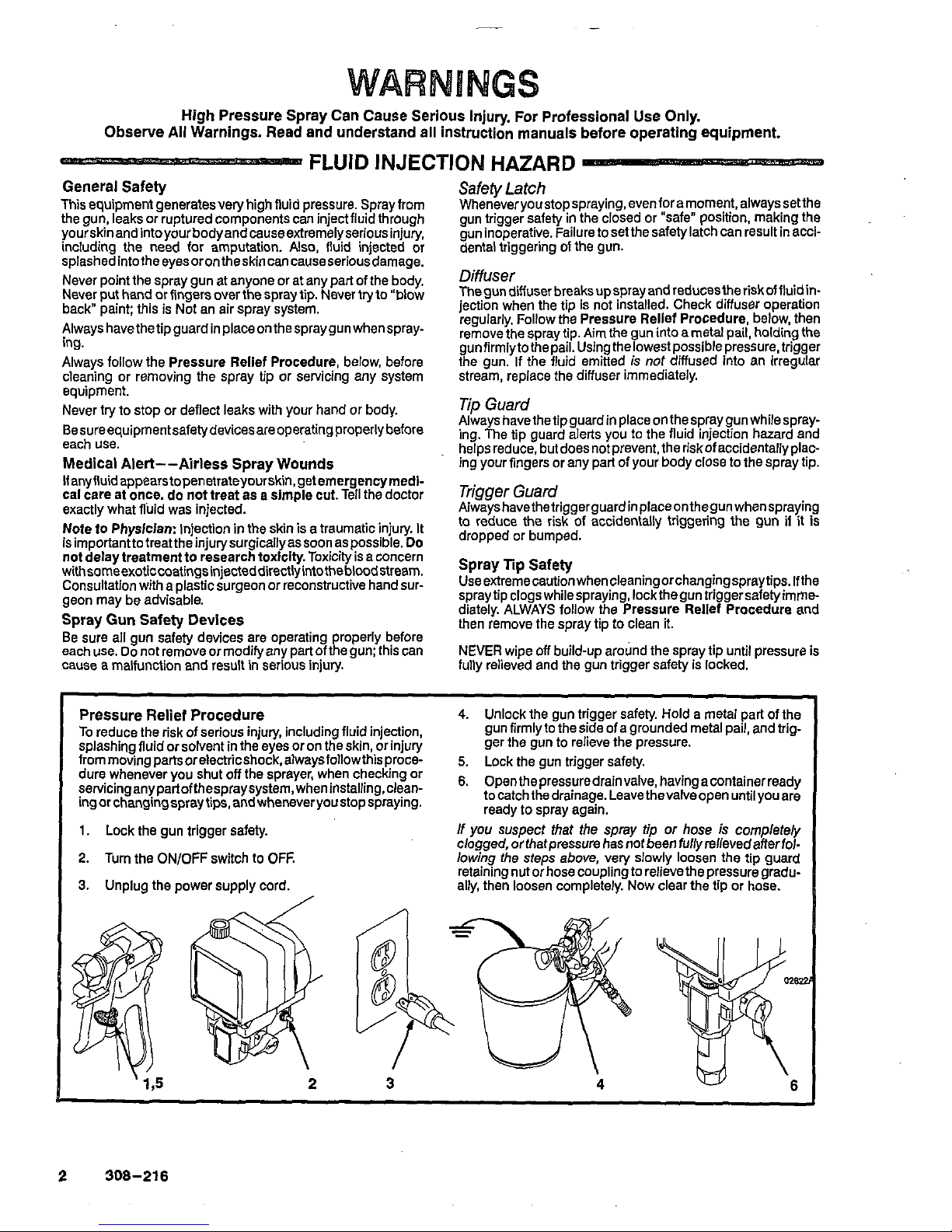
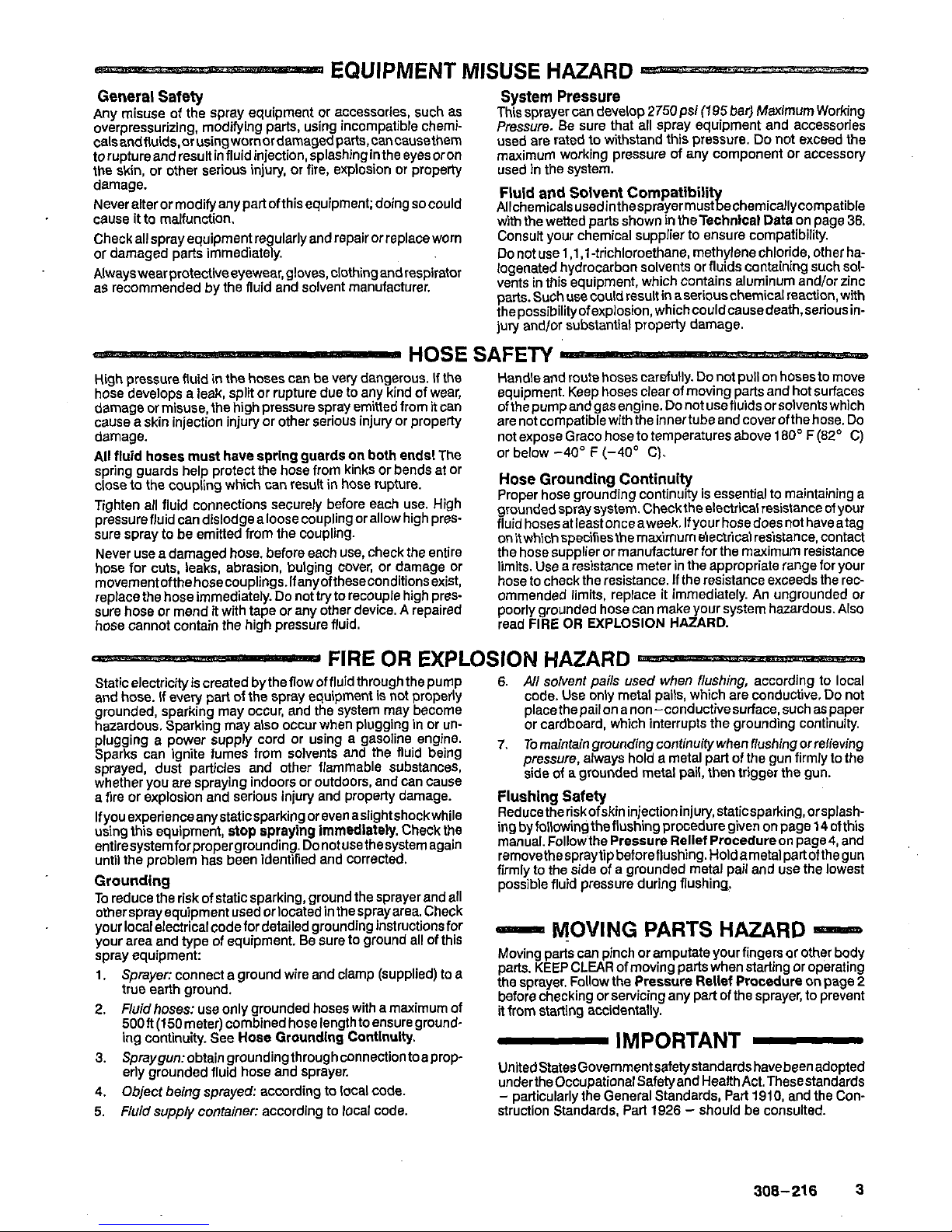
To
reduce the risk of serious injury, including fluid injection,
Pressure Relief
Procedure
4.
Unlock the gun trigger safety. Hold a metal part
of
the
splashing fluid or solvent in the eyes or on the skin, or injury
gun firmlyto the side
of
a grounded metal pail, and trig
frommovingpartsorelechicshock,alwaysfollowthisproce-
5.
Lock the oun trimer safetv.
ger the gun to relieve the pressure.
1.
Lock the
gun
trigger safety.
2.
Turn the
ON/OFF
switch
to
OFF.
3.
Unplug the power supply cord.
If you suspect that the spray
tip
or
hose
is
completely
clogged, orthatpressure has not been fullyrelievedafterfollowing the steps above, very slowly loosen the tip guard
ally, then loosen completely. Now clear the tip or hose.
retaining nut or hose coupling to relievethe pressure gradu-
2
308-216
Page 3
EQUIPMENT MISUSE HAZARD
-
General
Safety
Any misuse of the spray equipment or accessories, such as This sprayer
can
develop 2750psi(195 bar) Maximum Working
calsandfluids,orusingwornordamagedparts,cancausethem
used are rated to withstand this pressure.
Do
not
exceed the
overpressurizing. modifying parts, using incompatible chemi- Pressure. Be sure that all spray equipment and accessories
toruptureandresultinfluidinjection,splashtngintheeyesoron
maximum working pressure of any component or accessory
the skin, or other serious injury, or fire, explosion or property used in the system.
damage.
NeveranerormodifyanYPartofthisequiPment;doingsocould
Allchemicalsusedinthesprayermust
echemicallycompatible
Fluid
and
Solvent Compatiblh
cause
it
to malfunction.
Checkallsprayequipmentregularlyandrepairorreplaceworn
Consult your chemical supplier
to
ensure compatibility.
w'm the wetted parts shown
in
theTechnicai Data
on
page
36.
or
damaged parts immediately.
Alwayswearprotectiveeyewear,gloves,clothingandrespirator
logenated hydrocarbon Solvents or fluids containingsuch
501-
Do
not use
1,1,1
-trichloroethane, methylene chloride, other ha-
a5 recommended by the fluid and solvent manufacturer.
vents in this equipment, which contains aluminum andlor zinc
parts.Suchusecouldresultinaseriouschemicalreaction,with
thepossibilityofexpiosion,whichcouldcausedeath,seriousin-
jury and/or substantial property damage.
System
Pressure
.
Y
HOSE
SAFETY
High pressure fluid
in
the hoses can be very dangerous. If the
Handle and route hoses carefully.
Do
not
pull
on hosesto move
hose develops a ieak, split or rupture due
to
any kind of wear,
equipment. Keep hoses clear of moving parts and hot surfaces
damage or misuse, the high pressure spray emitted from
it
can
ofthe pumpandgasengine.
Do
not usefiuidsor solventswhich
cause e skin injection injury or other serious injury or property
are not compatible with the innertube and cover ofthe hose.
Do
Ail fluid hoses
must
have spring guards
an
both ends! The or below
-40"
F
(-40'
C).
damage. not expose Graco hose
to
temperatures above 180' F
(82'
C)
hose for cuts, leaks, abrasion, bulging cover, or damage or
limits. Use
a
iesistance meter in the appropriate range for your
movementofthehosecouplings.Ifanyoftheseconditionsexist,
hose tocheckthe resistance.
If
the resistance exceeds the rec-
replace the hose immediately.
Do
nottry
to
recouple high pres-
ommended limits, replace
it
immediately. An ungrounded or
sure hose or mend
it
with tape or any other device. A repaired
poorly grounded hose can make your system hazardous. Also
hose cannot contain the high pressure fluid.
read
FIRE
OR
EXPLOSION
HAZARD.
~~ ~ ~~ ~~
~"I
~ ~
FIRE
OR
EXPLOSION HAZARD
Staticelectricityiscreated
bythe flow of fluidthroughthe pump
6.
All
solvent pails used when
flushing,
according
to
local
and hose.
If
every part of the spray equipment is
not
properly
code. Use only metal pails, which are conductive.
Do
not
grounded, sparking may occur, and the system may become
placethepailonanon-conductivesurface,suchaspaper
hazardous. Soarkino mav also occur when plugging
in
or un-
or cardboard, which interrupts the grounding continuity.
plugging e power
;UPP&
cord or using a gasoline engine. 7. Tomaintain groundingcontinuitywhen flushingorrefieving
Sparks can ignite fumes from solvents and the fluid being
sprayed, dust particles and other flammable substances,
pressure, always hold
a
metal part
of
the gun firmly to the
whether vou are soravino indoors or outdoors. and can cause
side of a grounded metal pail, then trigger the gun.
.
"
-
a fire or explosion and s&ious injury and property damage.
Flushing
Safety
.....
~~~.~
,.~
.~.~~,
Grounding
To
reduce the risk of static sparking, around the Sprayer and all
...
....,
__
_.
.-
..
~~
-~
r-
-
possible fluid pressure during flushing.
othersprayequipmentusedorloc~t~dinthesprayarea.Check
your localelectricalcodefordetailed grounding instructionsfor
your area and type of equipment. Be sure
to
ground all of this
spray equipment:
1,
Sprayer: connect a ground wire and clamp (supplied)
to
a
true earth ground.
2.
Fluid
hoses: use only grounded hoses with a maximum of
500ft1150meter~combinedhoselenathtoensurearound-
-
VOVlMG
PARTS HAZARD
-
Moving parts can pinch or amputate your fingers or other body
parts. KEEP CLEAR of moving parts when starting or operating
the sprayer. Follow the Pressure Relief Procedure on page
2
before checking or servicing any pati of the sprayer, to prevent
it
from starting accidentally.
ing
continuity. See Hose Groundlng Continuity.-
-
IMPORTANT
-
3.
Spraygun:obtaingroundingthroughconnectiontoaprop-
4.
Object being sprayed: according to local code.
5.
Fluid
supply container: according to local code. struction Standards, Part
1926
-
should be consulted.
-.
-.
. - .
.
.
-
-.
-
-
erly grounded fluid hose and sprayer.
UnitedStatesGovernmentsafetystandardshavebeenadopted
underthe0ccupationalSafetyandHealthAct.Thesestandards
-
particularly the General Standards, Part
1910,
and the Con-
Page 4
Rbservb exclusivement I'usage professlonnel. Observer toutes
les
consignes de sbcuritb.
La pulvbrisatlon
A
haute presslon'peut causer des blessures trbs graves.
Bien
lire
et bien comprendre tous
les
manuels d'lnstructions avant d'utiliser
le
matbriel.
RISQUES
D'INJECTIOM
Cet appareil produit un fluide a tres haute pression. Le fluide
Consignes generales
de
sbcuritb
fuites ou de ruptures peut p4netrersous la peau ou A I'interieur
pulverise par le pistolet ou le fluide sous pression provenant de
du corps et entrainer des blessurestres graves, voir mhe une
amputation. Mbmesans &re sous pression. lefluideeclabous-
santouentrantdanslesyeuxpeutaussientrainerdesblessures
graves.
Ne Jamais pointer le pistolet vers quelqu'un ou vers une partie
quelconqueducorps.NeJamaismettrelamain0ulesdoigtssur
I'ajutage du pulv6risateur. Ne Jamais essayer de "refouler" la
peinture. Cet appareii N'est
Pasuncompresseurpneumatique.
Toujoursgarderlaprotectiondel'ajutageenplacesurlepistolet
pendant la pulverisation.
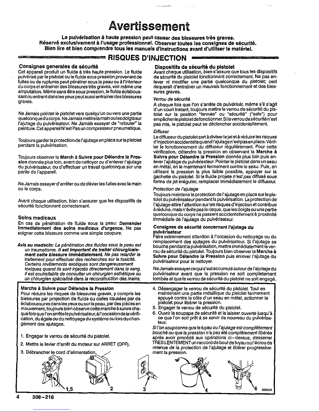
Toujours ObSeNer la March
a
Sulvre pour D6tendre
18
Presdon donnee plus loin, avant de nettoyer ou d'enleverl'ajutage
du pulverisateur, ou d'effectuer un travail quelconque sur une
partie de I'appareil.
ou le corps.
Ne Jamais essayerd'arrdter ou de devierles fuites avec la main
Avant chaque utilisation, bien s'assurer que les dispositis de
skurite fonctionnent correctement.
Solns medicaux
En cas de pen6tration de fluide sous la peau: Demander
soigner cette blessure comme une simple coupure.
lmrnedlaternent des soh medlcaux d'urgence. Ne pas
Avis au medecln: La penetration des fluides
sous
la peau est
un traurnatisrne.
I1
est important de waiter chiruqicale-
ment
cetle blesiura imm6diatement. Ne pas retarder le
traitement pour effectuer des recherches sur la toxiClt6.
Certains rev&tements exotiques
sont
dangereusement
toxiques quand ils
sont
inject& directernent dans le sang.
I1
est souhaitable de consulter
un
chirurgien esthbtique
ou
un
ChiNrCIien
sobcialisb
dans
la
reconstruction des
mains.
Avant chaque utiiisation, bien s'assure que tous
les
dispositifs
Dlspositifs de sbcuritb du pistolet
de securith du pistolet fonctionnent correctement. Ne pas enlever ni modifier une partie quelconque du pistolet: ceci
risquerait dentrainer
un
mauvars fonctionnement et des bles-
sures graves.
Verrou de securitd
A
chaque fois que l'on s'arrdte de pulv6riser, rndme s'il s'agit
d'un
court instant, toujours mettre le verrou de securite du pis-
tolet sur la position "fermbe" ou "securit6" ("safe") pour
emp~cherlepistoletdefonctionner.Sileverroudesecuriten'est
pas mis, le pistolet peut se declencher accidentellement.
Diffuser
d'injectionaccidentellequandI'ajutagen'estpasenplace.VBrif-
LediffuseurdupistoletsertBdiviserlejetet21reduirelesrisques
verification, dbtendre la pression en ObSeNant
la
Marche
b
ier le fonctionnement du diffuseur rbgulierement. Pour cette
lever I'ajutage du pulv6risateur. Pointer le pistolet dans un seau
Sulvre pour Detendre
la
Presslon donnee plus loin puis en-
en metal, en le rnaintenant fermement contre le seau. Puis, en
utilisant la pression la plus faible possible, appuyer sur
la
gachette du pistolet. Si
le
fluide projete n'est pas diffuse sous
forme de jet irregulier, remplacer immediaternent le diffuseur.
Protection de I'ajutage
Toujoursmaintenirlaprotectiondel'ajutageenplacesurlepis-
toletdupulv6risateurpendantlapulverisation.
Laprotectionde
I'ajutageattire I'attention sur
les
risquesd'injectionet contribue
Breduire,maisn'evitepaslerisque,quelesdoigtsouunepartie
quelconque du corps ne passent accidenteliement a proximite
immediate de I'ajutage du pulverisateur.
Consignes de shcurlte concernant I'ajutage
du
Faire extremement attention a lloccasion
du
nettoyage ou
du
pulverlsateur
remplacement des ajutages du pulvdrisateur. Si I'ajutage se
bouche pendant la pulv&isation, mettreimmediaternent lever-
Sulvre pour Detendre la Presslon puis enlever I'ajutage du
rou de sdcurite du pistolet. Toujours bien obsmer la Marche
a
pulverisateur pour le nettoyer.
NeJamaisessuyercequis'estaccumuleautourdeI'ajutagec
pulverisateur avant que la pression ne soit completeme1
tombbe et aue le verrou de skurite du oistolet ne soitenoaa'
".
blessures per projection de fluide ou celles causbes par de
Bclaboussuresdanslesyeuxousurlapeau,pardespiecesen
mouvement,toujoursbienobservecettemarcheasuivrecha-
5.
Engager le VerrOU de S6curite du Pistolet.
quefoisqueI'onarrdtelepulv8risateur,Bl'occasiondelaverifi-
6.
Ouvrir lasoupape de skurite et la laisser ouverte jusqu'a
cation,du6galeoudunettoyagedusyst&meoulorsduchan-
gement des ajutages. teur.
ce que
l'on
soit prdt a se servir de nouveau du pulvbrisa-
SiI'on soupconne que le
tuyau
ou I'ajutage est cornpl&tement
1.
Engager le verrou de securite du pistolet.
bouch6
ou
que la pression
n
'a
pas
Btb
cornpleternent liberee
apres avoir procede aux operations ci-dessus, desserrer
2.
Mettre le levler d'arrit du moteur sur ARRET (OFF).
4
308-216
Page 5

-
RISQUES EM CAS
DE
MAUVAISE UTILISATION DU MATERIAL
-
Conslgnes gbnbrales
de
securltk
Toute utilisation
anormale
de I'appareil de pulverisation ou des Ce pulverisateur peut produire une Pression
Maximum
De
Tra-
accessoiresromme,parexemple,lamisesousunepressionex-
mi
195
bar (2750lb/po2). S'assurer que tous les elements du
chimiques et
de
matiires incompatibles et I'utilisation de
pieces
pression maximum de travail de ce pulverisateur.
NE
PAS
cessive,
les
modifications
de
pieces, I'utilisation de produits pulverisateur et ses accessoires sont conqus pour resister B la
ruptures de pieces et entrainer une injection de liquide ou ou accessoires utilises avec cet appareil.
usees ou abides
peut
causer des degats B I'appareil ou des
depasserlapressionmaximumdetravaild'aucundeselements
d'autres degits.
d'autrbs blessures serieuses. un incendie, une explosi6n ou
Compatlblllte
chlmlque
des
corps
Eien s'assurer que tous les corps des solvants Utiliies sont
Ne Jamais alterer ou modifier une piece de cet appareil; ceci
chimiquementcompatiblesaveclespartiesmouilleesindiquees
risquerait d'entrainer son mauvals fonctionnement. dans les Technical Data, a page
36.
Toujours lire soigneuse-
Verifier rbgulihrement tout I'appareil de pulverisation et ses
mentlesdocumentsetbrochuresdufabricantdesfluidesetsol-
equipementsetreparerouremplacerimmediatementlespieces
vants utilises avant de s'en servir dans ce pulverisateur.
usees ou abimbes.
Presslon
-
MESURES DE SECURITE CONCERNANT LES TUYAUX FLEXIBLES
-
Lefluideahautepressioncirculantdanslestuyauxpeut~tretres
Manipulerlestuyauxavecprecautionetchoisirsoigneusement
dangereux. Encasdefuite sur letuyau, defissure, dechirureou
leur chemin. Ne pas deplacer lefluide en tirant sur le tuyau. Ne
tion, lesprojectionsdefluide haute pression quienproviennent
avec I'enveloppe interieure ou exterieure du tuyau. NE PAS ex-
ruptureBlasuitedel'usure,ded~gitsoud'unemauvaiseutilisa-
pasutiliserdefiuidesoudesolvantsquinesontpascompatibles
peuvententrainerdesblessuresgravesparpen~trationsousla
poser le tuyau
;1
des temperatures superieures
A
82°C
peau ou par contact, ainsi que des ddgats materiels.
(180°F)
ou inferieures a -4OOC (-40'F).
Tousles tuyauxtlexlbles doivent avolr des
ressorts
splrale
Contlnulte de la mlse la terre des tuyaux
gev~ter~a~orma~on~ep~~ures,debouc~e~oude~~~d~~u~~e~
tiellepourmaintenirlamisealaterredeI'ensembledevaporisa-
deprotectionauxboutslLesspiralesdeprotectioncontribuent
UnebonnecontinuitedelamiseBlaterredestuyauxestessen-
tuyauxquipourraiententrainerlarupturedutuyauBI'endroitdu
tion.Verifiezlaresistanceelectriquedevostuyauxafluideseta
raccord ou B son voisinage. air, au moins une fois par semaine. Si votre tuyau ne comporte
pas d'etiquette qui precise la resistance electrique maximurn,
fluide
SOUS
pression peut faire sau!er
un
raccord desserre ou avoir les
limites
de resistance maximum. UtiliSeZ
un
m&e de
Serrerfermementtouslesraccordsavantchaqueutilisation.Le
prenezcontactaveclefournisseurdetuyauxoulafabricantpour
produire un jet a haute pression s'echappant par
le
raccord.
resistance de la gamme aPPrOPri6e Pour VotretuYau etverifiez
Ne Jamais utiiiser un tuyau endommage. Ne Pas essayer de
remplacez le tuyau immediatement. Un tuyau sans mise
a
la
la resistance. Si celle-ci depasse les limites recommandees.
tuyau avec du ruban adhesif ou par tout autre moyen. Un tuyau risques pour votre systeme. Lisez aussi LES RISQUES DIN-
refaire le raccord d'un tuyau haute pression ni de reparer le terre ou avec une mise
A
la terre incorrecte peut entrainer des
repar6 ne peut pas resister au fiuide
SOUS
pression. CENDIE
OU
D'EXPLOSI6N ci-dessus.
RISQUES D'INCENDIE OU DEXPLOSIOM
-
De IUlectricit6 statique est produite par le passage du fluide
B
2.
Tuyaux fiexbles: Afin d'assurer la continuite de la mise a la
grande vitesse dans
la
pompe et dans les tuyaux. Si toutes les
pieces de I'appareil de puiverisation ne Sont pas convenable-
terre, n'utiliser que des tuyaux comportant une mise
a
la
men! relies B la masse ou B laterre, des 6tincelles peuvent se
terre et ayant une longueur maximum combinee de
150
m
(1
500
pieds). Se reporter egalement au paragraphe Contl-
produire et I'appareil risque d'Qre dangereux. Des etincelles
nuke
du clrcult de
mlse
B
la
terre des tuyaux.
peuventQgalementseproduireBI'occasiondubranchementou
3.
Pistolet: RBaliser la mise B la terre en le raccordant
Bun
sontsuffisantesDourallumerlesvapeursdesolvantsetlefluide
du debranchement du cord6n d'alimentation. Les 6tincelles tuyau flexible et
B
un pulverisateur dejje convenablement
relies a la terre.
pu~verise, les fines particules de poussiehre ainsi que d'autres
4.
Recipient ~a//mentation: observer
le
code
ou
les
ou
uneexplosion, ainsi que
des
blessures graveset des degits
substances inflammables, et elles peuvent causer un incendie mentations locales.
trouvant
B
au moins
6
m
(20
pieds) de I'appareil et de I'endroit
materiels,
~~~j~~~~ brancherle pulv&isateurdans une prisese
5.
Wets, materid
00
suhces rewant la pukdrisafion: ob-
server
le
code
ou
les rbglementations locales.
oh
se fait la pulverisation.
6.
Tousles seaux de solvants utilisbs pour le rincage: observer
S'ilseproduitdesetincellesd'electricitestatique,ousivousres-
le
code
ou
les reglementations
locales.
N'utiliser que des
sentezlamoindred~charge,arr~tezlmmedlatementlapulv~
saux m6talliques conducteurs de I'6lectricit6. Ne pas mettle
rlsatlon. Verifiezque lesystemeentierest bien mis alaterre. Ne
le seau sur une surface non conductrice comme sur du
vousservezpasdusystemeavantqueleproblemesoitidentifie
papier ou du carton car cela interromprait la continuite de
..
la mise a la terre.
et corrigd.
7. Pour consewer
la
continuit6
de
la mise
ii
la tene
quand
on
Mise
h
la
Perre
ou
B
la masse rince le materiel
ou
quand on libere
la
pression, toujours
Pour reduire les risques de production d'4tincelles d'6lectricitb maintenir une partie mdtallique du pistolet fermement ap-
statiaue.
le
oulverisateur et tous les Bauioements utilises ou se
puyb
contre le c6te
dun
seau en metal puis appuyer sur
trouvant dans la zone de pulv6risation doivent &re relies la
terre ou
ia
masse. Pour connaitre le detail des instructions de
Consulter le code ou les reglementations electriques locales.
miseBlaterredanslaregionetletypeparticulierd'equipement,
sont bien relies B la terre:
S'Assurer que tous Ies huipements de pulverisation suivants
1.
Pulverisateur: Brancher le cord6n d'alimentation
ou
la
ral-
longe qui doivent &e equip& d'une prise
B
3
fiches en
a
la terre. Ne pas utiliser d'adaptateur. Toutes les rallonges
bon etat, dans une prise de courant convenablement mise
doivent avoir
3
fils
et 6tre prevues pour 15 amperes.
,~
~,
~.
,
ia detente du pistolet.
Mesures de
skurite
concernant le rlncage
Pourreduirelesrisquesdeblessuresparpenetrationdelapeau
etlesrisquesd~sauxetincellesd'electricitestatiqueouauxecla-
boussures, observer IamarcheBsuivrepour
le
rincage donnee
B
la page 14 de ce manuel. Observer
la
"Marche Suivre pour
pukerisateur avant
le
rincage. Maintenir une partie m6tallique
Detendre la Pression" donnee
A
la 4 en enlever I'ajvtage
du
du pistolet fermement appuyee contre le cat6 d'un seau en
cage.
m~taletutiliserlapressionlaplusfaiblepossiblependantlerin-
308-216
5
Page 6

El
rociado a
alta
presi6n
puede
causar
graves lesiones. Solo
para
us0
profeslonal.
Respete
10s
avisos
de
advertencia.
Lea y entienda
todo
el
manual
de
Instrucci6nes
antes de
manejar
el
equipo.
-
PELIGRO
DE IMYECCION
DE
FLUID0
Seguridad general
Esteequipogeneraunfluidoaunapresi6nmuyalta.Elrociado
delapistola,losescapesdefluidooroturasdeloscomponentes
pueden inyectar fluido en la piel y el cuerpo y causar lesiones
amputaci6n.Tambien,elfluidoinyectadoosalpicadoenlosojos
extremadamente graves, incluyendo a veces la necesidad de
puede causar graves daiios.
Nunca apuntar la pistola hacia alguien
o
alguna parte del
cuerpo. Nunca colocar la mano
o
10s
dedos encima de la bo-
quilla.Nuncatratarde"hacerretornar1apintura";estenoesun
sistema de rociado de aire.
Siempre tener colocado el protector de la boquilla en la pis-
tolamientras se esta pulverizando.
Siempreseguirelprocedimientodedescargadepresion,dado
mhsabjo, antes de limpiar o sacar
la
boquilla o de dar servicioa
cualiquier equipo del sistema.
cuerpo.
Nunca tratar de parar
o
desviar
10s
escapes con la mano o el
Asegurarquetodoslosaparatosdeseguridaddelequipoestan
funcionando bien antes de cada uso.
Tratamiento
medico
Siparecieraqueunpocodefluidopenetr6lapiel,conseguirTra-
tamlento medico deurgencladelnmediato. notratarla herida como un simple corte. Decir al medico exactamente cua
fluido fue.
Aviso
a/ m6dico:
Si
se //ega a inyectar este fluido en la pie/ se
causa una lesi6n traumdtica.
Es
importante
tratar
guirtirgicamente la lesi6n a la brevedad posible.
No
demomr el tratamiento para investigar la toxicidad.
La
toxicidad es a/go de suma importancia en algunas
pin-
turas exdticas cuando se invectan directamente a/ torrente
r
Procedimiento de
descarga
de
presl6n
Parareducirel riesgode sufrirgraves lesiones corporales. incluyendo inyeccion
o
lesiones causadas por pie& en
procedimientoal
apagar lamaquina
pulverizadora, al revisar
movimiento
o
choque
electrico,
siempre seguir este
0
dar servicio acualquier parte del sistema de
pulverization,
al instalar, limpiaro cambiar ias boquillas, y cadavezque se
deja de pulverizar.
1.
Enganchar el pestillo de la pistola.
2.
Mover el interruptor electrico (ON/OFF) a la posicion
OFF (apagado).
3.
Desenchufar el cordon electrico.
1
Asegurarquetodoslosaparatosprotectoresdelapistolaesth
Aparatos
de
seguridad
de
la
pistola
pulveriradora
funcionando bien antes de cada uso. No sacar ni modificar
ningljnapieza de lapistolapues podriacausar el malfunciona-
mientodelamismaconlasconsiguienteslesionespersonales.
Pestillo de seguridad
Cada vez que se deje de pulverizar, aunque sea por un breve
momento, siempre colocar el pestlllo de seguridad en la posi-
puede llevar al disparo imprevisto de la pistola.
ci6n "cerrada"
lo
que deja la pistola inoperante. El no hacerlo
Difusor
El difusor de la pistola dispersa el chorro pulverizado y reduce
el riesgo de inyeccion cuando no est& instalada la boquilla.
Revisarcon regularidad elfuncionamiento del difusor. Seguirel
despubs sacar la boquilla. Apuntar la pistola a un balde metali-
procedimiento de descarga de preslbn, dado
mas
abajo. y
co,sosteni~ndolabienfirmecon~ael.U~lizandolapresi~nmas
bajo posible, disparar la pistola. Si el fluido emitido no sale dis-
persoenunchorroirregular,reemplazardeinmediatoeldifusor.
Protector de /a boquilla
Siempretenerel protectorde la boquillacolocadoen lapistola
contra el peligro de inyeccion y ayuda a reducir, per0 no evita,
mientras seesta pulverizando. Este protector llama laatendon
lacolocacionaccidentaldelosdedosocualquierotrapa~edel
cuerpo cerca de la boquilla.
Seguridad
de
la
boquilla
pulverizadora
Tenermuchocuidadoallimpiarocambiarlasboq.Sillega-
delapistoladeinmediato.Siempreseguirelprocedlmlentode
raaobstruirsemientrasestepulverizando,engancharelpestillo
descarga de presl6n y despues sacar la boquilla para
lim-
piarla.
sanguineo.
Sir4
convenientkconsultara
un
especialistaen
quillaantesdequesehayadescargadoporcompletolapresion
Nunca limpiar la acumulacion de plntura alrededor de la bo-
cirugia plistica
o
reconsfructiva de /as manos. y el
pestillo
este enganchado.
4
4.
Desenganchar el pestillo de la pistola. Sujetar una parte
metelica de la pistola bien firme contra un balde de
5.
Enganchar el pestilio de la pistola.
metal, y disparar la pistola para descargar la presion.
6.
Abrir la valvula de presi6n. Dejar la valvula de alivio de
presi6n abiarta hasta que se
est8
nuevamente list0 para
Si se sospecha que la boquilla
o
la manguera esta com-
pulverizar.
pletamente obstruida,
o
que no se ha descargado por com-
anterior,aflojarmuylentamentelatuercaderetenci6ndelpro-
pleto la presion despues de haber seguido el procedimiento
tector de la boquilla
o
acoplamiento de la punta de la man-
guera y descargar gradualmente la presion, despues,
aflojarlo por completo. Luego, despejar la boquilla
o
la man-
guera.
6
308-216
Page 7
Cualquier mal
us0
del equipo pulverizador o 10s
acCesorioS, tal
Seguridad general
como sobre presurizacih,
modification
de
piezas, us0 de
mat~rialesyproductosquimicosincompatibles,outilizaci6nde
pie& datiadas o desgastadas, puede hacen que se rompan y
causenlainyecci6ndefluidouotrasiesionescorporalesgraves,
incendio, explosi6n o dation a la propiedad.
Nunca alterar
o
modificar ningicna pieza de este equipo: el
hacerlo podria causar una averia.
Presi6n del sistema
fresi6n
De Trabajo Mdxima. Asegurar que todo el equipo pul-
estb pulverizadora puede desarrollar 195 barias
(2750
psi) De
verizadorysusaccesoriostienenlacapacidadparaaguantarla
presi6n maxima de trabajo de est& pulverizadora NO exceder
cesorio de este sistema.
la presi6n mAxima de trabajo de ningtjn componente
o
ac-
Compatibilidad de fluido
Siempreleerlasinstrucci6nesdelfabricantedelfluidoysolvente
antes de usarlos en est6 pulverizadora, dadas en la pagina
36.
Revisar con regularidad el equipo pulverizador y reparar
o
respiradero, tal
como
recomiendan ios fabricantes del fluido y
Siempre usar galas, guantes, vestimetas protectora y un~
reemplazar de inmediato las piezas datiadas
0
desgastadas. del solvente.
.~
-
SEGURIDAD
EM
EL US0 DE
US
MAMGUERAS
-
Elfluidoqueescapaaaltapresi6nporlasmangueraspuedeser
Manejarypasarcuidadosamentelasmangueras.Notirarde1as
muy
peligroso. Si en la manguerase desarrolla un escape, una
mangueras para mover el equipo. No usar fluidos
o
solventes
rotura
o
rajadura debldo a cualquier tip0 de desgaste, datio
o
que Sean incompatibles con el tub0 interno y la cubierta dela
maltrato. el chorro a alta presibn emitido por alii puede causar manguera. No exponer
las
mangueras a temperaturas sobre
una lesion por inyeccion
u
otras lesiones corporales graves
o
82-
c
(1800
R
0
baio -400
c
(-40"
R.
datios a la propiedad.
ITodaslasmanguerasparafluldostlenenquetenerguardas
de resorte en ambos extremosl Estas protegen
las
man-
manguera
guerascontradoblecesore~orce~urasenlosacop~amiento~o
Lacontinuidaddelcircuitodepuestaatierraapropiadoesesen-
cercade
ellos,
los
quepodrian
traducirse
en
rOturaS
de
la
man-
cialparamantenerconectadoatierraelsistemapulverizador.Es
"llP?P
indispensable revisar la resistencia electrica mAxima de las
.
Continuidad del circuit0 de puesth a tierra de la
yv","
fluido a alta presi6n puede desalojar un acoplamiento suelto
o
Antes de usarlas, Apretar bien firmes todas las conexiones. El
dejar que por
el
escape un chorro a alta presion.
Nuncausarunamangueraqueestadatiada.Siempre,revisarla
en buscade cortaduras, escapes, abrasion, cubierlaabultada,
o
acoplamientos sueltos o dahados. Si llegara a encontrarse
cualquiera de estbs condiciones, reemplazar de inmediato la
manguerasdeaireydefluidoporlomenosunavezalasemana.
Si la manguera no tiene una etiqueta en la cual se especifica la
fabricantedelamangueraparalainformacibnsobreloslimites
resistencia electrica, ponerse en contact0 con el proveedor
o
de resistencia. Usar un metro de resistencia en la gama
apropiade para comprobar la resistencia; si excede
10s
limites
recomendados,
reemplazarladeinmediato.
Esmuyarriesgado
tener una manouera sin Duesth a tierra
o
con
la ouesta a tierra
manguera. NOintentarracoplar
unamangueradealtapresibn
en malas conkcidnes. 'Leer tambien la informacibn~sobre
o
enmendarla con cinta adhesiva u OtrO material similar. Una RIESGO
DE
INCENDIO
0
EXPLOSION.
mas
arriba.
manguera que ha sido remendada no aguante el fluido a alta
presi6n.
-
PELIGRO DE INCENDIQ 0 EXPLOSION
-
.,
El flujo a aka velocidad del fluido al pasar por la bomba y manguera crea electricidad estatica. Si todas las partes del equipo
pulverizador no tienen buena tierra, pueden ocurrir chispas,
convirtiendo al sistema en algo peligroso. Tambien, pueden
producirse chispasaenchufar
o
desenchufarel cordon electri-
co. Est& chispaspueden
inflamarlosvaporesdelossolventes
yelchorrodefluidopulverizado,particulasdepolvoyotrassus-
tanciasinflamables,seaalairelibreobajotecho,loquepodria
causarunaexplosionoincendioygraveslesionescorporalesy
dafios al a propiedad. Enchufar siempre la pulverizadora a un
tomacorrientequeseencuentreaporlomenos6m(ZOpies)de
la maquina y del area que se va a rociar.
choqueelectricomientrasseusaelequipo,de)ardepulverlzar
Si ocurre una chispade electricidad estatica o incluso un ligero
de Inmediato. Revisar todo el sistema en busca de una tierra
y solucihado el problema.
apropiada.Nousardenuevoe1sistemahastahaberidentificado
Peusta a tierra
Para reducir
el
reisgo de chispas estaticas, conectar a tierra
la
pulverisadora y todo el otro equipo de pulverisar que se use
0
se encuentre en el lugar que se va a rociar. Consultar el codigo
electric0 delalocaiidad para las
instruccionessobrelasconex-
de conectar a tierra todo este
equipo pulverisador:
iones a tierra exigidas para la zona
y
tip0 de equipo. Asegurar
1.
Pufverizadora: enchufar el cordbn electrico, o cable exten-
sor, cada uno un enchuf de trhs patas en buen estado, a
un tomacorreinte con puesat a tierra aporpiado. No usar un
trhs hilos y una capacidad de 15 amperios.
adaptador. Totos
10s
cables extensores tienen que tener
2.
Mangueras para fluidos: usar solamente mangueras con
puesta a tierra de una longitud combinada de 150
m
(500
pies), para asequrar buena continuidad a tierra. Referirse
tambien al parrafo sobre continuidad a tierra de la
manugeura.
3.
Pistola: hace la puesth a tierra conectandola a una manguera de fluido y pulverizadora bien conectadas a tierra.
4.
Suministrar
un
fecipiente: de acuerdo al codigo de la
localidad.
5.
Objeto que se estd rociando: de conformidad con el
codigo local.
6.
Todos
/os
baldes de solvente usados durante el lavado. de
de metal, que Sean conductivos. no colocar el balde en
conformidad
con
el codigo local. Usar solamente baldes
interumpe la continuidad a tierra.
una superficie no conductiva,
como
papel o canon, que
7.
Para mantenar la continuidad a tierra durante el lavado
o
descarga de
presion,
siempre apoyar una parte metaiica
de la pistola bien firme contra el costado del balde
de
metal, despues apretar el gatillo.
Seguridad durante el lavado
Para reducir el riesgo de que se inyecte o salpique fluido en la
siempre seguir las Instrucciones Para
El
Lavado. dadas en la
piel,
o
que ocurra una descarga de electricidad estatica,
pbgina.14 Seguir el procedlmlento de descarga de presibn
en la pigna
6,
y quita la boquilla rociadora antes de lava,:
Apoyarunapartemetalicadelapistolabienfirmecontraelcos-
tadodeunbaldedemetalyusarlepresi6nmasbajaposiblede
fluido durante el lavado.
308-216
7
Page 8
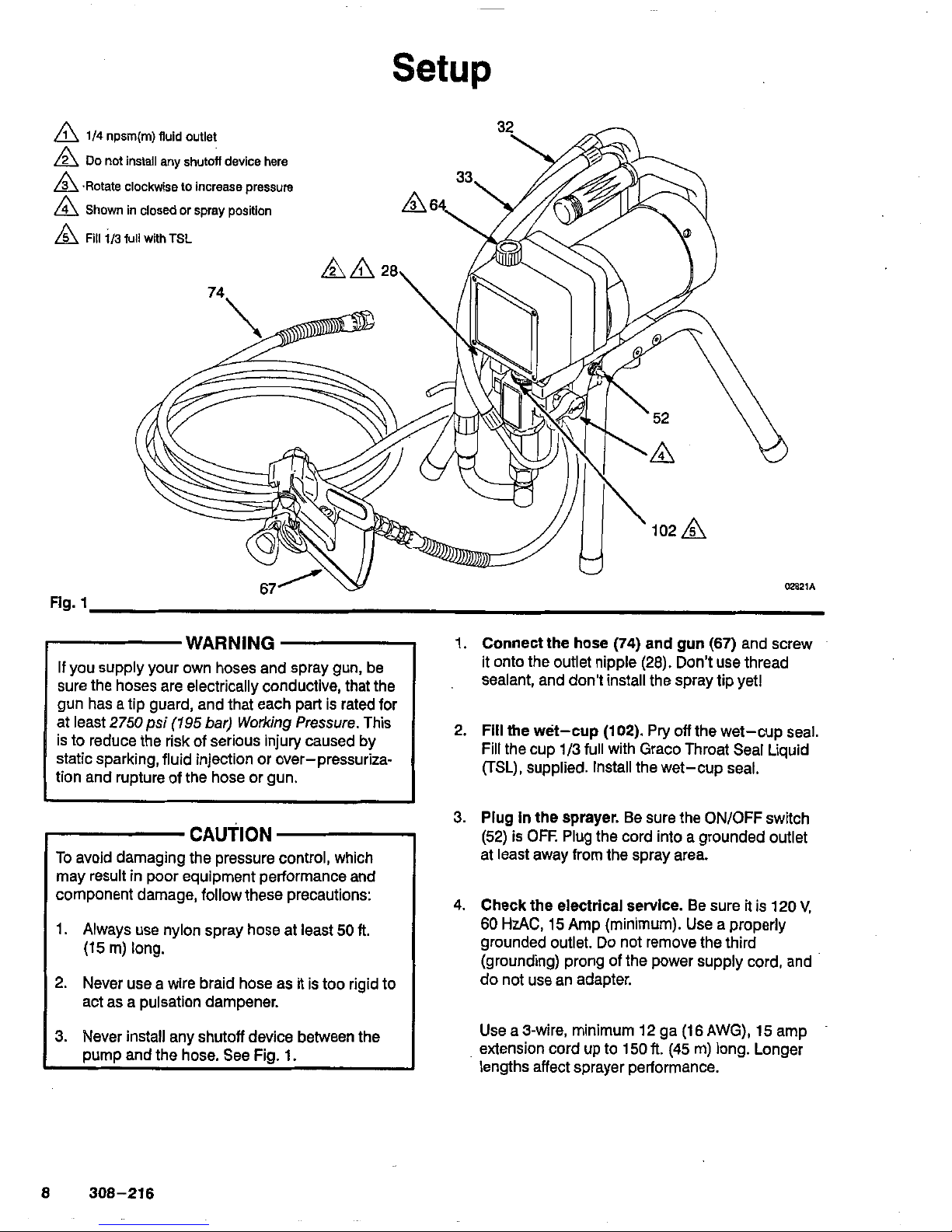
Setup
A
1/4
npsm(m) fluid outlet
A
DO
not install
any
shutoff
device here
A
.Rotate clockwise to Increase pressure
A
Shown in closed or spray position
A
Fill
1/3
full with
TSL
74.
Fig.
32
r
WARNING
sure the hoses are electrically conductive, that the
If
you supply your own hoses and spray gun, be
at least
2750psi
(195
bar) Working Pressure. This
gun has a tip guard, and that each part is rated for
is
to reduce the risk of serious injury caused by
static sparking, fluid injection or over-pressuriza-
tion and rupture
of
the hose or gun.
CAUTION
To
avoid damaging the pressure control, which
may result
in
poor equipment performance and
component damage, follow these precautions:
1.
Always
use
nylon spray hose at least
50 ft.
(15
m) long.
2.
Never use a wire braid hose as it is too rigid to
act as a pulsation dampener.
3. Never install any shutoff device between the
pump and the hose. See Fig.
1.
1.
Connect the hose
(74)
and
gun
(67)
and screw
it onto the outlet nipple
(28).
Don't use thread
sealant, and don't install the spray tip yet1
2.
Fill
the wet-cup (102).
Pry
off
the wet-cup seal.
Fill the cup 1/3 full with Graco Throat Seal Liquid
(TSL),
supplied. Install the wet-cup seal.
3.
Plug
in
the sprayer.
Be sure the ON/OFF switch
(52) is OFF. Plug the cord into a grounded outlet
at least away from the spray area.
4.
Check the electrical
service.
Be sure
it
is
120
V,
60
HzAC,
15
Amp (minimum). Use a properly
grounded outlet.
Do
not remove the third
(grounding) prong
of
the power supply cord, and
do not use an adapter.
Use a 3-wire, minimum
12
ga
(16
AWG),
15
amp
extension cord up to
150
R.
(45
m) long. Longer
lengths affect sprayer performance.
8
308-216
Page 9
Setup
5.
Ground the sprayer and spray system.
WARNING
To
reduce the risk of static sparking, ground the
pump
and
all other equipment used or located
in
the
tailed grounding instructions for your area and type
spray area. Check your local electrical code for de-
of equipment. Ground all of this equipment.
I
I
a. Sprayer: plug into a properly grounded outlet.
Do
not use an adapter. Extension cords must
have three wires and be rated for at least
15
amps.
b.
Fluid
hoses: use only grounded hoses with a
maximum of
500
ft
(150
m) combined hose
length
to
ensure grounding continuity. See
Hose Grounding Continulty.
c. Spraygun: obtain grounding through connec-
tion to a properly grounded fluid hose and
sprayer.
d.
Object being sprayed: according to local code.
e.
Fiuid
supply container: according
to
local code,
f. A// solvent pails used when flushing, accord-
are conductive.
Do
not place the pail on a
ing
to
local code.
Use
only metal pails, which
non-conductive surface, such as paper or
cardboard, which interrupts the grounding
continuity.
g.
To
maintain grounding Continuity when fiush-
ing
or
relieving
pressure,
always hold a metal
pari
of
the gun firmly to the side of a
grounded metal pail, then trigger the gun.
6.'
Flush the pump
to
remove the oil which was
left
page
14.
in
to
protect pump parts after factory testing.
See
7.
Prepare the paint
according to the manufactur-
Stir the paint
to
mix pigments. Strain the paint
er's recommendations. Remove any paint skin.
through a fine nylon mesh bag (available at most
paint dealers) to remove particles that could clog
the gun filter or spray tip. This is an important
step toward trouble-free paint spraying.
Operation
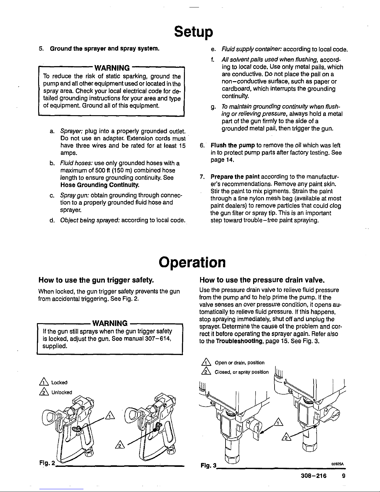
How to use the gun trigger safety.
When locked, the
gun
trigger safety prevents the gun
from accidental triggering. See Fig.
2.
WARNING
If the gun still sprays when the gun trigger safety
is locked, adjust the gun. See manual
307-614,
supplied.
A
Locked
How to
use
the pressure drain valve.
from the
pump and to help prime the pump. If the
Use the
pressure drain valve
to
relieve fluid pressure
valve
senses
an over pressure condition, it opens au-
tomatically
to
relieve fluid pressure.
If
this happens,
stop spraying immediately, shut
off
and unplug the
sprayer. Determine
the
cause
of
the problem and cor-
rect it before operating the sprayer again. Refer also
to
the
Troubleshooting,
page
15.
See Fig.
3.
A
Open or drain, position
A
Closed, or
spray
position
jj
(Ii
Fig.
3
W
W825A
308-216
9
Page 10
Operation
How
to
use
the pressure control.
The pressure control controls the motor operation
so
the sprayer maintains constant fluid pressure at the
pump outlet. Turn the pressure control knob fully
the knob clockwise to increase
pressure.
See
Fig.
4.
counterclockwise to obtain the
minimum setting. Turn
Fig.
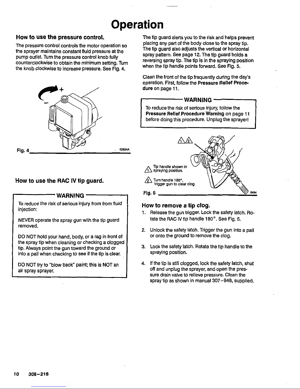
How
to
use
the
RAC
IV
tip
guard.
WARNING
To reduce the risk of serious injury from from fluid
injection:
NEVER operate the spray gun with the tip guard
removed.
DO
NOT hold your hand, body, or a rag in front of
the spray tip when cleaning or checking a clogged
tip. Always point the gun toward the ground or
into a pail when checking to see if the tip is clear.
DO
NOT try to "blow back" paint; this
is
NOT an
air spray sprayer.
The tip guard alerts you to the risk and helps prevent
placing any part of the body close to the spray tip.
The tip guard also adjusts the vertical or horizontal
spray pattern. See page
12.
The tip guard holds a
reversing spray tip. The tip
is
in the spraying position
when the tip handle points forward. See Fig.
5.
Clean the front of the tip frequently during the day's
operation. First, follow the Pressure Relief Procedure on page 11.
WARNING
To reduce the risk of serlous injury, follow the
Pressure Relief Procedure Warning on page 11
before doing this procedure. Unplug the sprayer1
Tip
handle shown In
Fig.
5
How
to
remove
a
tip
clog.
1.
Release the gun trigger. Lock the safety latch.
Ro-
tate the RAC
IV
tip handle
180'.
See Fig.
5.
2.
Unlock the safety latch. Trigger the gun into a pail
or onto the ground to remove the clog.
3.
Lockthe safety latch. Rotate the tip handle to the
spraying position.
4.
If
the tip is still clogged, lock the safety latch, shut
off
and unplug the sprayer, and open the pressure drain valve to relieve pressure. Clean the
spray tip as shown in manual
307-848,
supplied.
10
308-216
Page 11
Startup
Pressure Relief Procedure.
WARNING
To
reduce the risk of serious injury, including fluid
the eyes or on the skin, moving parts or electric
injection, injury from splashing
fluid
or solvent
in
shock, follow this procedure when shutting
off
the
sprayer; checking or servicing the spray system;
installing, cleaning or changing spray tips; and
whenever you stop spraying.
1.
Lock the gun trigger safety.
2.
Turn the ON/OFF switch to OFF.
3. Unplug the power supply cord.
4.
Unlock the gun trigger safety. Hold a metal part of
the
gun
to relieve pressure.
the gun firmly to a grounded metal pail. Trigger
5.
Lock the gun trigger safety.
6.
Open the pressure drain valve, having a container
drain valve open until you are ready to spray
ready to catch the drainage. Leave the pressure
again.
li
you suspect that the spray
tip
or
hose is completely
clogged,
or
that pressure has not been
ful/y
relieved
the the tip guard retaining
nut
or hose coupling to re-
affer following the steps above, VERY SLOWLY loosen
lieve pressure gradually, then loosen completely.
Startup
Procedure.
help ensure the sprayer is ready to operate and that
Use this procedure each time you start the sprayer to
you start
it
safely.
NOTE: If this is a first-time startup, flush the sprayer.
See page
14.
NOTE: Refer to Fig. 1 and the other figures referenced in the text as you start the sprayer.
1.
Open the pressure drain valve
(42).
2.
Don’t Install the spray tip until the pump
is
primedl
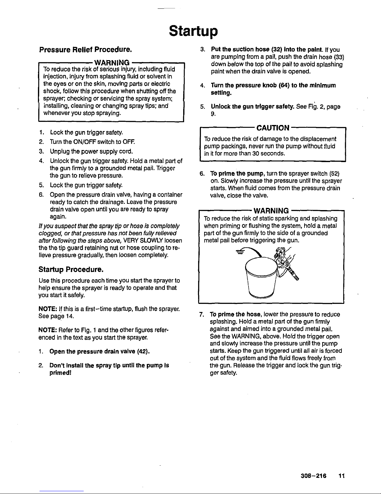
3.
Put
the suction hose
(32)
into the paint.
If
you
are pumping from a pail, push the drain hose
(33)
down below the top of the pail to avoid splashing
paint when the drain valve is opened.
4.
Turn the pressure knob
(64)
to the minimum
5.
Unlock the gun trigger safety.
See Fig.
2,
page
setting.
9.
To
reduce the risk of damage to the displacement
pump packings, never run the pump without fluid
in
it for more than 30 seconds.
6.
To
prime the pump,
turn the sprayer switch
(52)
starts. When fluid comes from the pressure drain
on. Slowly increase the pressure until the sprayer
valve, close the valve.
WARNING
To reduce the risk of static sparking and splashing
when priming or flushing the system, hold a metal
part of the gun firmly to the side of a grounded
metal pail before triggering the gun.
7.
To
prime the hose,
lower the pressure to reduce
splashing. Hold a metal part of the gun firmly
against and aimed into a grounded metal pail.
See the WARNING, above. Hold the trigger open
and slowly increase the pressure until the pump
starts. Keep the
gun
triggered until all air is forced
out of the system and the fluid flows freely from
the gun. Release the trigger and lock the gun trigger safety.
308-216
11
Page 12
Startup
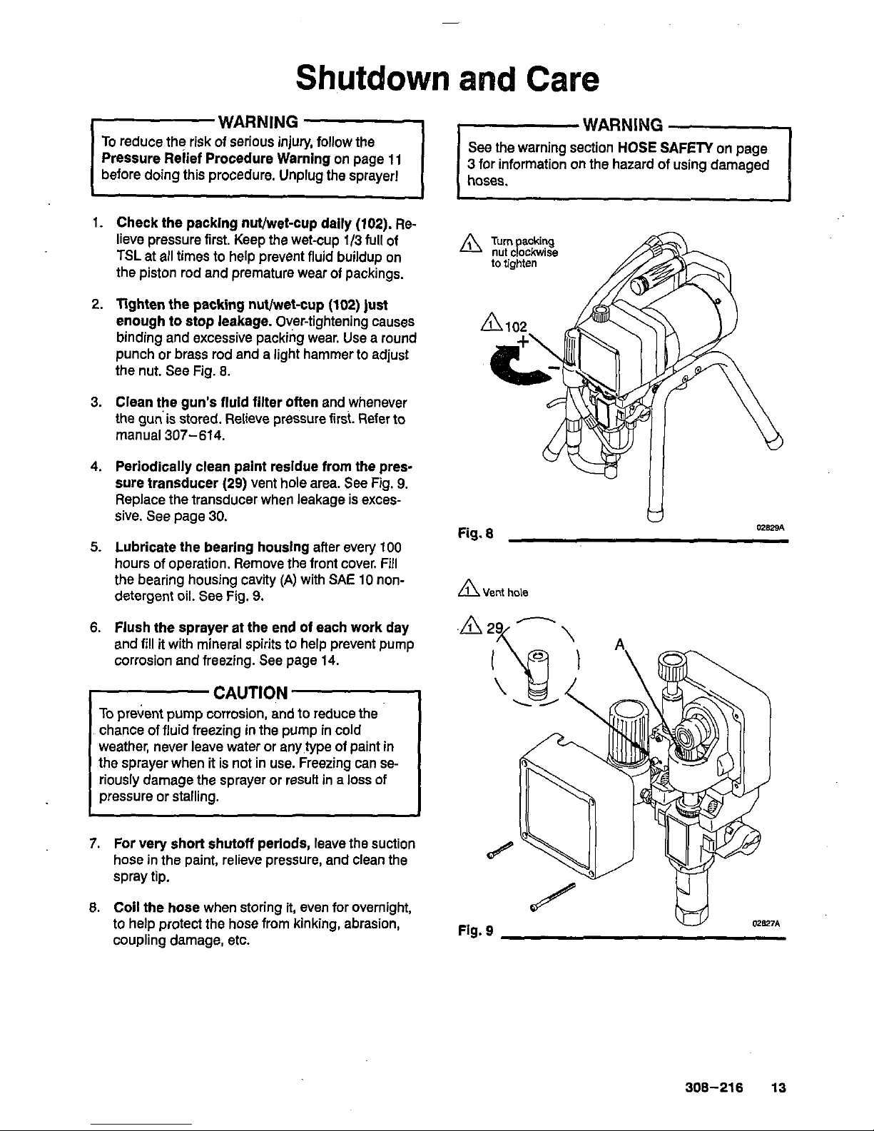
8.
Check all
fluld
connections
for
leaks. Relieve
NOTE
Spray patterns will change as tips wear.
pressure before tightening any connections. Change the spray tip
if
adjusting the pressure will not
9.
Install the spray
tip.
Lock the gun trigger safety
first1 See manual
307-848
for how to install the tip.
improve the spray pattern.
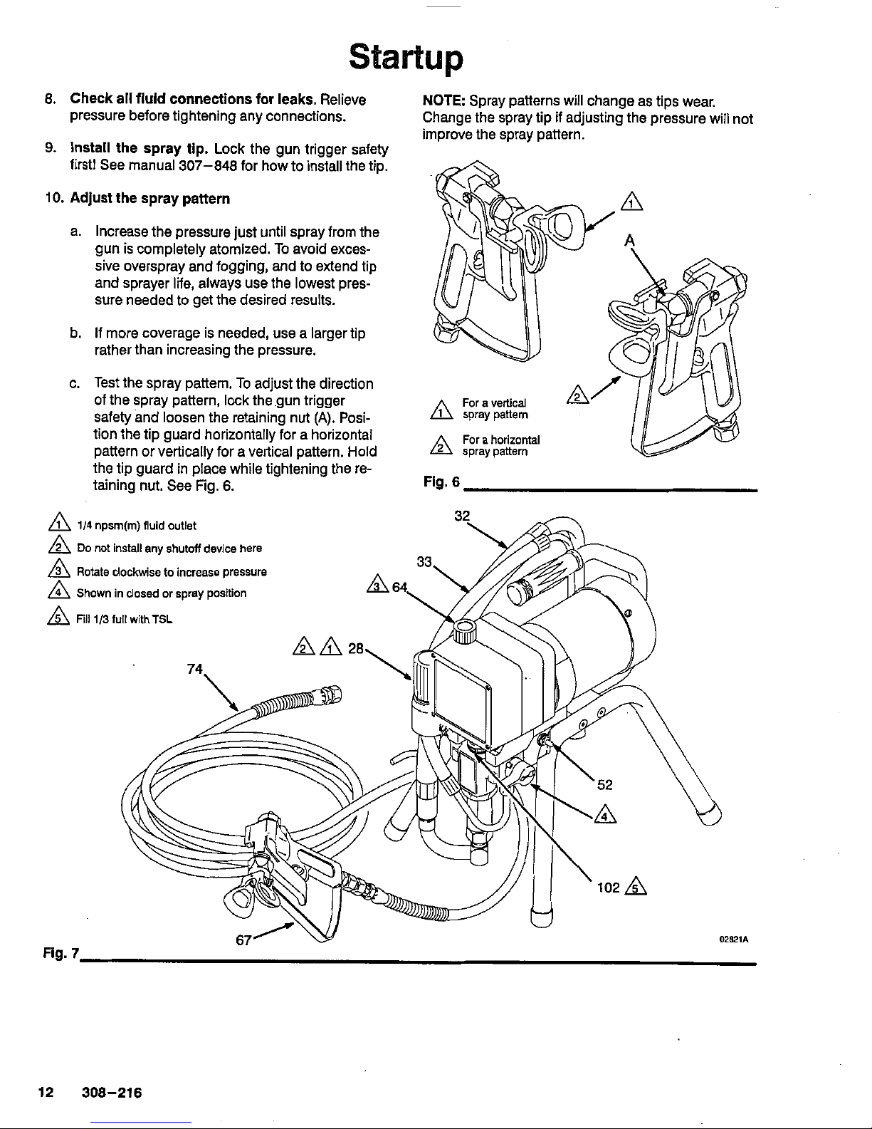
10.
Adjust the spray pattern
a. Increase the pressure just until spray from the
gun is completely atomized.
To
avoid excessive overspray and fogging, and to extend tip
and sprayer life, always use the lowest pressure needed to get the desired results.
b.
If more coverage
is
needed, use a larger tip
rather than increasing the pressure.
c. Test the spray pattern. To adjust the direction
of the spray pattern, lock the gun trigger
safety and loosen the retaining nut
(A).
Posi-
tion the tip guard horizontally for a horizontal
pattern or vertically for a vertical pattern. Hold
the tip guard in place while tightening the retaining nut. See Fig.
6.
Fig.
6
A
1/4
npsm(m) fluid outlet
A
DO
not
install any
shutoff
device here
A
Rotate clockwise to increase pressure
A
Shown in closed or spray position
A
Fill
1/3
full
with
TSL
Fig.
7
02821A
12 308-216
Page 13
Shutdown
and
Care
WARNING
To
reduce the risk of serious injury, follow the
Pressure Relief Procedure Warning
on
page 11
before doing this procedure. Unplug the sprayer!
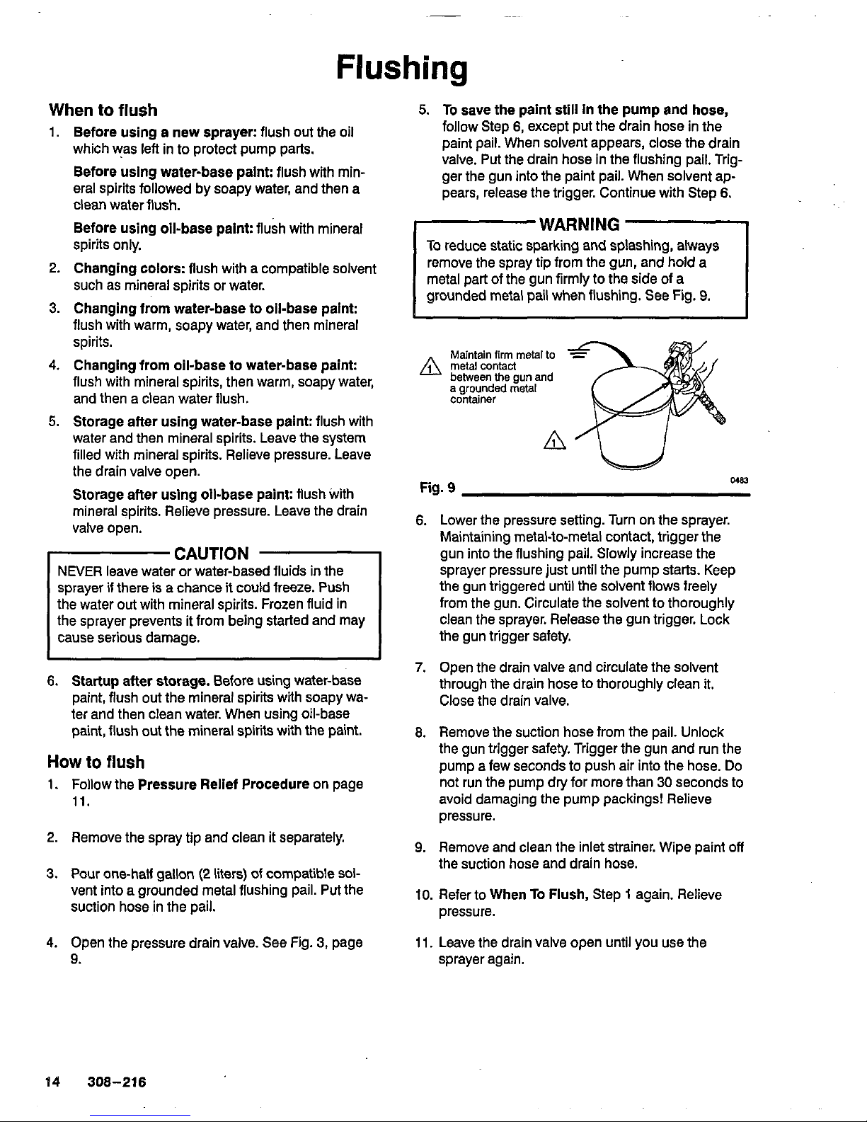
1.
Check the packlng nWwet-cup daily
(102).
Re-
lieve pressure first. Keep the wet-cup
1/3
full of
TSL
at all times to help prevent fluid buildup on
the piston rod and premature wear of packings.
2.
Tighten the packing nut/wet-cup
(102)
just
enough to stop leakage. Over-tightening causes
punch or brass rod and a light hammer to adjust
binding and excessive packing wear. Use a round
the nut. See Fig.
8.
3. Clean the gun’s fluid filter often and whenever
the gunis stored. Relieve pressure
first.
Refer to
manual 307-614.
4.
Periodically clean paint residue from the pres-
sure transducer
(29)
vent hole area. See Fig.
9.
sive. See page
30.
Replace the transducer when leakage is exces-
5.
Lubricate the bearing houslng after
every
100
the bearing housing cavity
(A)
with
SAE
10
non-
hours of operation. Remove the front cover. Fill
detergent oil. See Fig.
9.
6.
Flush the sprayer at the end of each work day
and fill it with mineral spirits to help prevent pump
corrosion and freezing.
See
page 14.
CAUTION
To
prevent pump corrosion, and
to
reduce the
chance of fluid freezing in the pump in cold
the sprayer when it is not in use. Freezing can se-
weather, never leave water or any,type of paint in
riously damage the sprayer or result in
a
loss
of
pressure or stalling.
7.
For
very short shutoff periods, leave the suction
hose in the paint, relieve pressure, and clean the
spray tip.
8.
Coil the hose when storing
it,
even for overnight,
to help protect the hose from kinking, abrasion,
coupling damage, etc.
WARNING
See the warning section
HOSE
SAFETY
on
page
3 for information
on
the hazard of using damaged
hoses,
u
Fig.
8
U
028234
Fig.
9
308-216 13
Page 14
Flushing
When
to
flush
1.
Before usina a new swaver:
flush
which was
left
in to prdted pump parts.
out
the oil
Before using water-base paint:
flush with mineral spirits followed by soapy water, and then a
clean waterflush.
Before using oil-base paint:
flush with mineral
spirits only.
2.
Changing colors:
flush with a compatible solvent
such as mineral spirits or water.
3.
Changing from water-base to oil-base paint:
flush with warm, soapy water, and then mineral
spirits.
4.
Changing from oil-base to water-base paint:
flush with mineral spirits, then warm, soapy water,
and then a clean water flush.
5.
Storage afler using water-base paint:
flush with
water and then mineral spirits. Leave
the
system
the drain valve open.
filled with mineral spirits. Relieve pressure. Leave
Storage after using oil-base paint:
flush with
mineral spirits. Relieve pressure. Leave the drain
valve open.
CAUTION
NEVER
leave water or water-based fluids
in
the
the water out with mineral spirits. Frozen fluid in
sprayer if there is a chance
it
could freeze. Push
the sprayer prevents it from being started and may
cause serious damage.
I
I
6.
Startup after storage.
Before using water-base
paint, flush out the mineral spirits with soapy wa-
ter and then clean water. When using oil-base
paint, flush out the mineral spirits with the paint.
How
to
flush
1.
Follow the
Pressure Relief Procedure
on page
11.
2.
Remove the spray tip and clean it separately.
3.
Pour one-half gallon
(2
liters) of compatible
sol-
vent into a grounded metal flushing pail. Put the
suction hose in the pail.
4.
Open the pressure drain valve. See Fig.
3,
page
9.
5.
To
save the paint
still
In the pump and
hose,
follow Step
6,
except put the drain hose in the
paint pail. When solvent appears, close the drain
valve. Put the drain hose in the flushing pail. Trigger the gun into the paint pail. When solvent ap-
pears, release the trigger. Continue with Step
6.
r
WARMING
To
reduce static sparking and splashing, always
metal pari of the gun firmly to the side
of
a
remove the spray tip from the gun, and hold a
grounded metal pail when flushing.
See
Fig.
9.
A
metal contact
Maintain
firm
metal to
behveen
the
gun
and
a grounded
metal
container
6.
Lower the pressure setting. Turn
on
the sprayer.
Maintaining metal-to-metal contact, trigger the
gun into the flushing pail. Slowly increase the
sprayer pressure just until the pump starts. Keep
the gun triggered until the solvent flows freely
from the gun. Circulate the solvent to thoroughly
the gun trigger safety.
clean the sprayer. Release the gun trigger. Lock
7.
Open the drain valve and circulate the solvent
through the drain hose to thoroughly clean it.
Close the drain valve.
8.
Remove the suction hose from the pail. Unlock
the gun trigger safety. Trigger the gun and run the
pump a few seconds to push air into the hose.
Do
avoid damaging the pump packings! Relieve
not run the pump dry for more than
30
seconds to
pressure.
9.
Remove and clean the inlet strainer. Wipe paint
off
the suction hose and drain hose.
10.
Refer to
When To Flush,
Step 1 again. Relieve
pressure.
11.
Leave the drain valve open until you use the
sprayer again.
14
308-216
Page 15
Troubleshooting
To
reduce
the
risk
of
serious
injury,
follow
the
Pressure Relief Procedure
on
page
11
before
doing
this
procedure.
Unplug
the sprayer1
Basic
Problem
Solving
Checkeverything
in
the
guide
before
disassembling
the
sprayer.
YPE
OF
PROBLEM
luid pressure
lechanical
lectrical
JTE:
Thaw SDraver
if
watt
MHAT TO CHECK
f
check
is
OK.
(10
to
next check
I,
Check pressure control knob setting. The pump
won't develop much pressure
if
it is at minimum
setting
(fully
counterclockwise).
used.
See
page
10.
.I
!.
Check for a clogged spray tip or fluid filter,
if
I-
Check for frozen or hardened paint in pump
fan
at
back
of
motor by hand.
See
page
19.
(20).
Using a screwdriver, carefully try to rotate
?,
Check pump connecting rod pin
(17).
It must be
completely pushed into connecting rod
(15),
and retaining spring
(1
8)
must be firmly in con-
necling rod groove.
See
Fig.
16,
page
22.
1,
Check for motor damage. Remove drive housing assembly
(11).
See
page
28.
Try
to
rotate
motor fan by hand.
I,
Check electrical supply with volt meter. Meter
should read
105-125
VAC.
-
T
-
F,
-
N
-
E
b
NC
I
A
?r or water-based paint has frozen in
it,
due to exposure to low temperatures, by placing in a warm
area.
Do
not
try
tcstart sprayer
until
completely thawed or damage
to
motor andlor start board may occur.
If
paint hardened
(dried) in sprayer, the pump packings (page
22)
and/or pressure transducer (page
30)
must be replaced.
?.
Check extension cord for visible damage. Use a
volt meter or test lamp
at
extension cord outlet
to check.
3.
Check sprayer power supply cord
(50)
for vis-
1.
Check motor brushes for the following:
a.
Loose
terminal screws.
b.
Broken or misaligned brush springs.
ible damage such as broken insulation or wires.
c.
Brushes binding in holders.
d. Broken leads.
e.
Worn brushes.
on both sides
of
motor. Check both brushes.
NOTE
The brushes do not wear at same rate
WHAT TO
DO
When check
is
not
OK,
refer
to
this column
1.
Slowly increase pressure setting to
see
if
motor starts.
2.
If
tip is still clogged, relieve pressure: refer to separate gun or tip instruction manual for tip cleaning. Clean the filter,
if
used.
1.
Thaw. Plug
in
sprayer and turn
on.
Slowly
starts. If
it
doesn't,
see
NOTE, below.
increase pressure setting to
see
if
motor
2.
Push pin into place and secure with
spring retainer.
3.
Replace motor
(4)
if
fan won't turn.
See
page
26.
1.
Reset building circuit breaker; replace
building
fuse.
Trv another outlet.
-
2.
Replace extension cord.
3.
Replace power supply cord.
See
page
27.
4.
Refer to page
21.
a. Tighten.
b.
Replace broken sprlng andlor align
spring with brush
c. Clean brush holders. Remove carbon
with small cleaning brush. Align brush
leads with
slot
in
brush holder to as-
sure free vertical brush movement.
d.
Replace brushes
e.
Replace brushes
if
less
than long.
308-216
15
Page 16

Basic
Problem
Solving
YHAT TO CHECK WHAT TO
DO
checkis
OK,
go
to next check
When
check is not
OK,
refer
to
this
column
.
Check motor armature commutator for burn
spots.
aouaesandextremerouahness.
Remove
motor Eovir and brush inspectron plates to
check. See page 21.
.
Checkmotorarmatureforshorts usina armature
I
~
5.
Remove motor and have motor shop
I
resurface commutator
if
possible. See
page
26.
16.
Replace motor. See page 26.
tester (growler) or perform motor tesL
See page 19.
.
Check leads from pressure control and motor to
7.
Replace loose terminals; crimp
to
leads.
motor start board (47) to be sure they are securely fastened and properly mated.
Be sure male terminal blades are straigh
and firmly connected to mating part.
~~
,Check motor start board (47) by substituting
8.
Replace board. See page 27.
with
a
good board. See page 27.
I
CAUTION:
Do
not perform this check until mo-
tor armature is determined to be good.
A
bad
motor armature can burn
out
a good board.
and white power cord terminals; connect volt 27.
should read VAC. Unplug sprayer.
meter to these leads. Plug in sprayer. Meter
.
Check power supplycord
(50).
Disconnectblack
9.
Replace power supply cord. See page
0.
Check ON/OFF switch-(52). Disconnect the
'E
wire between motor start board (47) and switch
and connect volt meter between exposed
terminal
on
switch and power cord's white wire.
Plug
in
sprayer and turn
ON.
Meter should read
VAC. Turn
off
and unplug sprayer.
1.
Check motor thermal cutout switch. Connect
ohmmeter between motor's red leads. Meter
should read
1
ohm maximum..
2.
Remove pressure control (64) and check microswitch operation with ohmmeter:
(1)
With pressure knob at lowest setting and
stem pushed into control, readings should
be: white &black
=
1
ohm max.
white &red
=
open.
(2) With pressure knob at highest setting,read-
white
ti
red = 1
ohm max.
ings should be: white
&
black = open;
3.
Check pressure transducer
(29)
for hardened
paint
or damaged or
worn
components.
See
page
30.
10.
Replace ONlOFF switch. See page 27.
11.
Allow motor to cool. Correct cause of
overheating.
If
switch remains open aftel
motor cools, replace motor.
-
12.
Replace pressure control. See page
30.
-~
~~ ~
13.
Replace transducer. See page
30.
Thor-
ough system flushing
will
help extend
lifl
of transducer.
Intermediate Problem
Solving
~~ ~ ~
TYPE
OF
PROBLEM
WHAT TO CHECK
If
checkis
OK.
(10
to
next check
Low output
1.
Check for worn spray tip.
.-
!
When check
is
not
OK
refer to this column
redace tio. See Your seDarate
aun
or
tiD
'
manual.
'
2.
Be sure pump does not continue to stroke when 2. Service pump. See page
22.
gun
trigger
is
released. Plug
in
and turn
on
sprayer. Prime with paint. Trigger gun momentarily, then release and lock safety latch. Relieve
pressure, turn
off
and unplug sprayer.
16
308-216
Page 17
Intermediate Problem
Solving
YPE
OF
PROBLEM
ow output (continued)
Vain valve leaks
iansducer leaks
lo
output: motor runs anc
lump strokes
Jo
output: motor runs
bui
ump does not stroke
WHATTO CHECK WHAT TO
DO
If check
is
OK.
GO
to
next check
When check
is
not
OK.
refer
to
this column
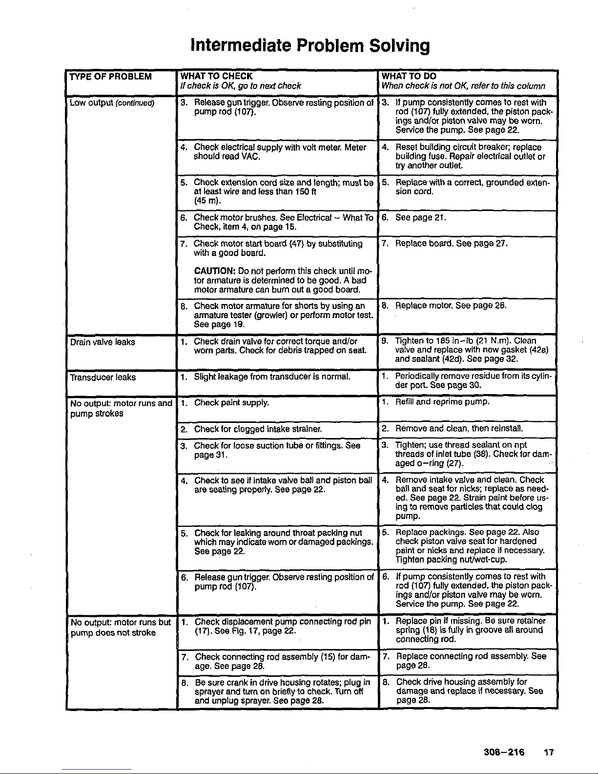
3.
Release gun trigger. Observe resting position
of
3.
If
pump consistently comes to rest with
pump rod (107).
I
ings andlor piston valve may be worn.
rod (107) fully extended, the piston pack
Service the pump. See page
22,
4.
Check electrical supply with volt meter. Meter 4. Reset building circuit breaker; replace
should read VAC.
I
building fuse. Repair electrical outlet or
I
try anoiher outlet.
6.
Check motor brushes. See Electrical - What
To
6.
See page 21.
7.
Check motor start board (47) by substituting 7. Replace board. See page
27.
Check, item
4,
on page 15.
with
a good board.
CAUTION
Do
not perform this check until mo-
tor armature is determined to be good.
A
bad
motor armature can burn
out
a good board.
8.
Check motor armature for shorts by using an
8.
Replace motor. See page 26.
armature tester (growler) or perform motor test.
See page 19.
worn parts. Check for debris trapped
on
seat. valve and replace with new gasket (42a)
1. Check drain valve for correct torque andlor 9. Tighten to 185 in-lb (21 Nm). Clean
and sealant (42d). See page 32.
1.
Slight leakage from transducer is normal.
1. Periodically remove residue from its cylin.
1.
Check paint supply.
1,
Refill and reprime pump.
der port. See page 30.
2. Check for clogged intake strainer,
3.
Check for loose suction tube or fittings. See
page 31.
4. Check to see
if
intake valve ball and piston bail
are seating properly. See page
22.
5. Check for leaking around throat packing
nut
which may indicate worn or damaged packings.
See page 22.
6.
Release gun trigger. Observe resting position
01
pump rod (107).
1.
Check displacement pump connecting rod pin
(17). See Fig. 17, page
22.
2. Remove and clean, then reinstall.
3.
Tighten: use thread sealant on npt
threads
of
inlet tube
(38).
Check for dam.
aged O-ring (27).
ball and seat for nicks; replace as need-
ed. See page 22. Strain paint before
us-
ing
to
remove particles that could
clog
Pump.
5.
Replace packings. See page 22.
Also
check piston valve seat for hardened
paint or nicks and replace
if
necessary.
Tighten Dackincl nWwet-cup.
4. Remove intake valve and clean. Check
6.
If pump consistently comes to rest with
rod (107) fully extended. the piston pack.
ings andlor piston valve may be worn.
Service the pump. See page 22.
-~
~ ~ ~
I.
Replace pin
if
missing. Be sure retainer
spring
(18)
is
fully
in
groove all around
connecting rod.
7.
Check connecting rod assembly (15) for dam- connecting rod assembly. See
age. See page
28.
.
I
8.
Be sure crank in drive housing rotates; plug
in
8.
Check drive housing assembly for
..
soraver and turn
on
brieflv to check. Turn
off
damaqe and reolace if necessaty. See
and unplug sprayer. See page
28.
I
page28.
308-216
17
Page 18

Intermediate Problem
Solving
TYPE
OF
PROBLEM
WHAT TO CHECK WHAT TO
DO
If
check
is
OK,
go
to
nexl
check When check is not
OK,
refer
to
this
column
I
Spray pattern variations
1.
Spray tip worn beyond sprayer pressure
1.
Replace spray
tip.'
capability.
NOTE
A
smaller size tip will provide
I
longer life.
2.
Check transducer
(29)
for wear or damage.
3.
Replace pressure control.
See
page
30.
3.
Check pressure control
(64)
for
smooth
2.
Replace transducer. See page
30.
operation.
I
4.
Check Low
output
section,
oaae
17.
I
CAUTION:
Do
not perform this check until
motor armature
is
determined to be good.
A
bad motor armature can burn out a good board.
I
I
I
Circuit breaker opens after asic Problems - Electrical' on
sprayer operates for
5
to
10
minutes.
..
I
opens as soon as sprayer
around throat. Replace pump packings.
if
tightening tightens packings on rod, restricts
'prayer
is
turned
On.
sprayer until corrected.
-
is plugged into outlet
and
1.
If
voltage
is
too high, do not operate
1.
Check electrical supply with volt meter. Meter
Building circuii breaker
should read VAC.
2.
Check tightness of pump packing nut. Over-
2.
Loosen packing nut. Check for leaking
pump action, damages packings.
3.
Replace motor. See page
26.
3.
Check for damaged motor.
necessary.
See
page
22.
I
should
be
infinity with
ON/OFF
switcl
zero with switch
ON.
I
I
CAUTION:
A
short in motor circuit can damage
switch and or motor start board
(47).
I
I
I
Unit will not run on gener-
power
ator but does run on AC
1.
Use
AG
power or a different generator
1.
Check the generator's "peak" voltage. This
sprayer will not run
if
the peak voltage
is
above
19ov.
18
308-216
Page 19

Motor
Test
WARNING
To
reduce the risk of serious injury, follow the
Pressure Relief Procedure Warning
on
page
11
before doing this procedure. Unplug the sprayer1
For checking armature, motor winding and brush
electrical continuity.
Setup
Remove the drive housing. See page
28.
This is to
test is due to the motor and not to worn gears in the
ensure that any resistance you notice in the armature
drive housing.
Remove the motor brush inspection covers
(A).
See
Fig.
11.
Remove the junction box screws
(56).
Lower the junc-
tion box. Disconnect the
two
leads (C) from the motor
to the board
(47).
See Fig.
12.
Armature Short Circuit Test
Remove the handle
(24)
and the fan cover
(B).
See
Fig.
11.
028Z9A
Spin the motor fan by hand.
If
there are no shorts, the
motor will coast
two
or three revolutions before com-
ing to a complete stop.
If
the motor does not spin
freely, the armature
is
shorted and the motor must be
replaced. See page
26.
Armature, Brushes, and Motor Wiring
Open Circuit Test (Continuity)
Connect the
two
black motor leads together with a
test lead. Turn the motor fan by hand at about
two
revolutions per second.
When turning the fan on a DC motor, normally you
turning resistance, or no turning resistance, check
sense an even, pulsing resistance. If there is irregular
and repair the following as needed: broken brush
springs, brush leads, motor leadsi loose brush termi-
nal screws or motor lead terminals; worn brushes.
See page
21.
If there is still uneven or no turning resistance, replace
the motor. See page
26.
59
Flg.
12
308-216
19
Page 20
General Repair Information
To reduce the risk of serious injury, follow the
Pressure Relief Procedure on page 11 before
doing this procedure. Unplug the sprayer1
Tool
List
These are the tools required
to
service all parts
of
the
sprayer.
3/8”
Allen@ wrench:
pump
manifold
3/16
Allen@ wrench: gear housing, legs, handle
#1
Phillips@ screwdriver: junction box,
3/8”
socket wrench: motor mount
pressure control, front cover
5/8”
socket wrench: drain valve, outlet fiftings,
13/16”
socket wrench: drain valve
onloff
switch boot, piston
1-1/4” socket wrench: pump inlet valve
1/2” open end wrench:
pump
rod
11/16’’ open end wrench: piston jam
nut
15/16’’ open end wrench: flats ofinlet tube
1
-3/4”
open end wrench:
pump
jam nut
5/64” drive pin: drain valve
pin
3“
needle nose pliers: wiring,
onloff
switch
Torque wrenches: various fasteners
Hammer
&
punch: packing nut
1.
When disconnecting wires
in
the junction box
assembly, use needle nose pliers
to
separate
mating connectors.
2.
When reconnecting the wires, be sure the flat
blade
of
the insulated male connector is centered
in the wrap-around blade of the female
connector.
CAUTION
tion, be sure
to
properly mate connectors, and
To reduce the risk of a pressure control malfunc-
wire could loosen the connector from the wire.
never pull on a wire
to
disconnect
it.
Pulling on a
3.
Route wires carefully through the drive housing
and motor. Avoid pinching the wires between the
junction box and the motor or pressure control.
CAUTION
performance or damage to the pressure control.
Improper wire routing can result in poor sprayer
4. Keep all screws,
nuts,
washers, gaskets, and
electrical fittings removed during repair procedures. These parts are not normally provided with
replacement assemblies.
5.
Test your repair before regular operation
to
be
sure the problem is corrected.
6. If the sprayer
does
not operate properly, verify
that everything was done correctly. Also refer
to
the Troubleshooting Guide, pages
15-19,
to
help
identify other possible problems and solutions.
WARNING
To reduce the risk of serious injury, including electric shock, DO NOT touch any moving parts or
electrical parts with your fingers or a tool while
inspecting
the
repair.
Shut
off
the sprayer and unplug it as soon as
you
complete the inspection.
Reinstall all covers, gaskets, screws and washers
before operating the sprayer.
During operation, the motor and drive housing
become very hot and could burn your skin if
touched. Flammable materials spilled on the hot,
bare motor could cause a fire or explosion.
20
308-216
Page 21
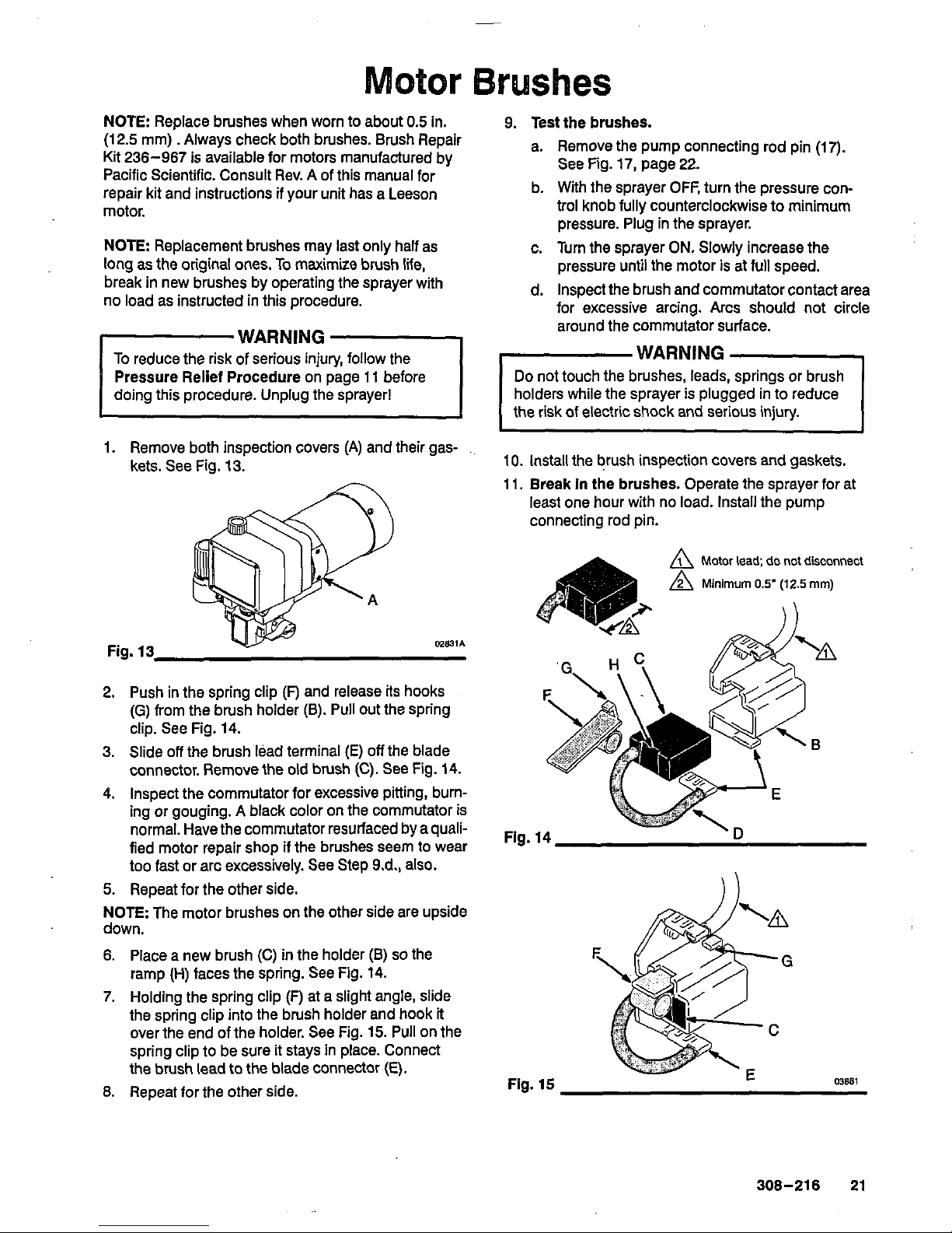
otor
Brushes
NOTE:
Replace brushes when worn to about
0.5
in.
9.
Test the brushes.
(12.5
mm).. Always check both brushes. Brush Repair
Kit
236-967
is available for motors manufactured by
a. Remove the pump connecting rod pin
(17).
Pacific Scientific. Consult Rev. A of this manual for
repair kit and instructions if your unit has a Leeson
b. With the sprayer OFF, turn the pressure con-
See Fig.
17,
page
22.
rnntnr
trol knob fully counterclockwise to minimum
...-.-..
pressure. Plug in the sprayer.
NOTE
Replacement brushes may last only half as c. Tum the sprayer
ON.
Slowly increase the
long
as
the original ones.
To
maximize brush lie, pressure until the motor
is
at full speed.
no load as instructed in this procedure.
break in new brushes by operating the sprayer with
d.
Inspect the brush and commutator contact area
for excessive arcing. Arcs
should
not circle
around the commutator surface.
j
To reduce the risk
of
WARN'NG
serious injury,
-1
follow the
WARNING
-,
Pressure Relief Procedure on page
11
before
Do
not touch the brushes, leads, springs or brush
doing this procedure. Unplug the sprayer1
holders while the sprayer is plugged in to reduce
the risk of electric shock and serious injury.
1.
Remove both inspection covers (A) and their gas-
~ ~~
kets. See Fig.
13. 10.
install the brush inspection covers and gaskets.
11.
Break
In
the brushes. Operate the sprayer for at
least one hour with no load. Install the pump
connecting rod
pin.
A
Motor
lead;
do
not disconnect
A
Minimum
0.5" (12.5
mm)
Fig.
13
2.
Push in the spring clip
(F)
and release
its
hooks
(G)
from the brush holder
(E).
Pull out the spring
clip. See Fig.
14.
3.
Slide
off
the brush lead terminal
(E)
off
the blade
connector. Remove the
old
brush (C). See Fig.
14.
4.
Inspect the commutator for excessive pitting, burning or gouging.
A
black color on the commutator is
normal. Have the commutator resurfaced bya quali-
F,g.
,4
fied motor repair shop if the brushes seem to wear
too fast or arc excessively. See Step
9.d.,
also.
5.
Repeat for the other side.
NOTE:
The motor brushes on the other side are upside
down.
6.
Place a new brush (C)
in
the holder
(E)
so
the
7.
Holding the spring clip (F) at a slight angle, slide
02831A
ramp (H) faces the spring. See Fig.
14.
the spring clip into the brush holder and hook
it
over the end of the holder. See Fig.
15.
Pull on the
spring clip to be sure it stays in place. Connect
the brush lead to the blade connector
(E).
Fig.
15
8.
Repeat for the other side.
03881
308-216
21
Page 22
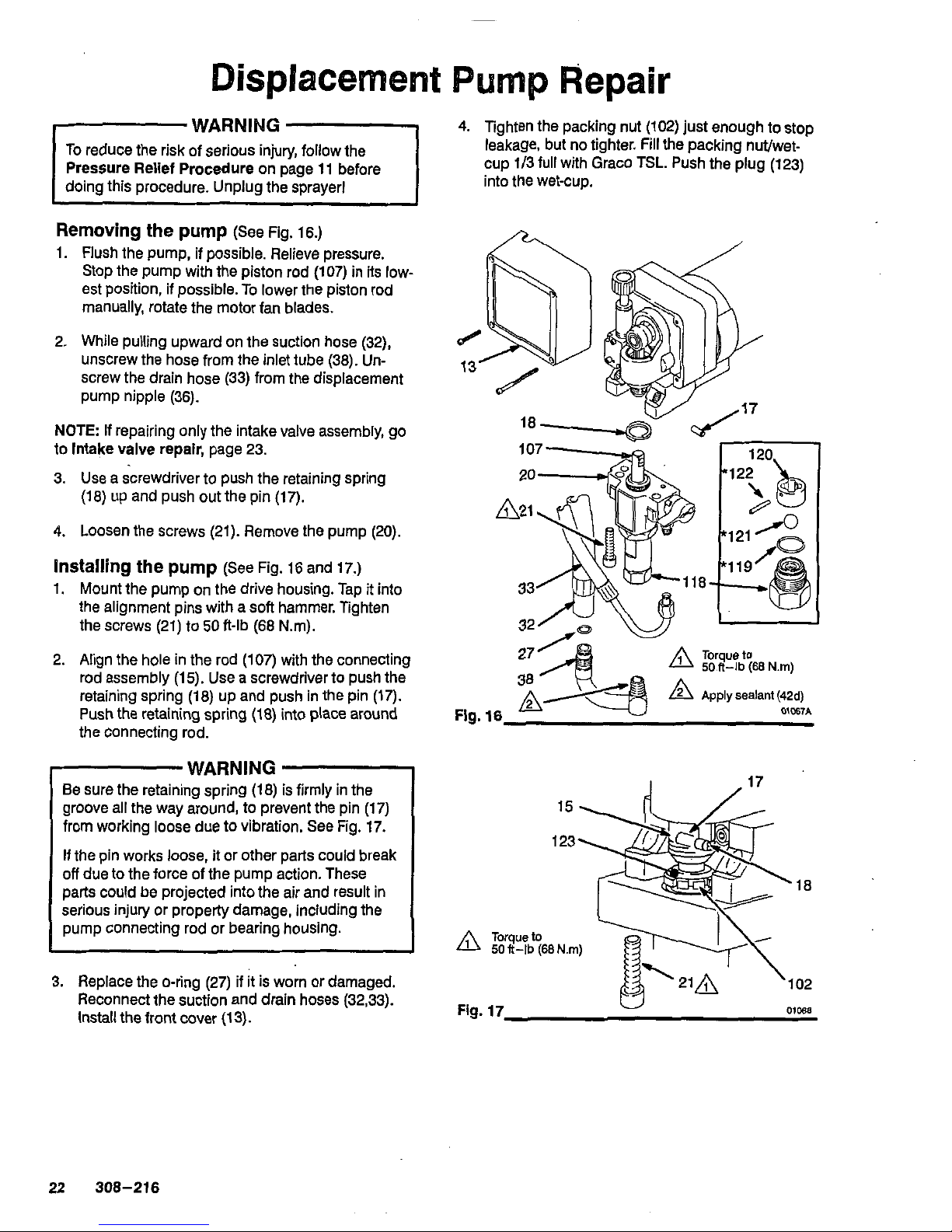
WARNING
To
reduce the risk of serious injury, follow the
Pressure Relief Procedure
on page
11
before
Removing
the
pump
(See
Fig.
16.)
1.
Flush the pump, if possible. Relieve pressure.
Stop the pump with the piston rod
(107)
in its low-
est position, if possible.
To
lower the piston rod
manually, rotate the motor fan blades.
2.
While pulling upward on the suction hose
(32),
unscrew the hose from the inlet tube
(38).
Un-
screw the drain hose
(33)
from the displacement
pump nipple
(36).
NOTE:
If
repairing only the intake valve assembly, go
to
Intake
valve
repair,
page
23.
3.
Use
a screwdriver to push the retaining spring
(18)
up and push out the
pin
(17).
4.
Loosen the screws
(21).
Remove the pump
(20).
installing
the
pump
(See Fig.
16
and
17.)
1.
Mount the pump on the drive housing. Tap it into
the alignment pins with a soft hammer. Tighten
the screws
(21)
to
50
ft-lb
(68
N.m).
2.
Align the hole in the rod
(107)
with the connecting
rod assembly
(1
5).
Use a screwdriver to push the
retaining spring
(18)
up and push in the pin
(17).
Push the retaining spring
(18)
into place around
the connecting rod.
WARNING
Be sure the retaining spring
(18)
is firmly in the
groove all the way around, to prevent the pin
(17)
from working loose
due
to vibration. See Fig.
17.
off
due to the force of the pump action. These
If the pin works
loose,
it
or other parts could break
serious injury or property damage, including the
parts could be projected into the air and result in
pump connecting rod or bearing housing.
3.
Replace the O-ring
(27)
if
it
is
worn or damaged.
Reconnect the suction and drain hoses
(32,33).
Install the front cover
(13).
4.
Tighten the packing nut
(102)
just enough to stop
cup
1/3
full with Graco
TSL.
Push the
plug
(123)
leakage, but no tighter. Fill the packing nut/wet-
into the wet-cup.
15
123
18
102
Fig.
17
OlW
22 308-216
Page 23
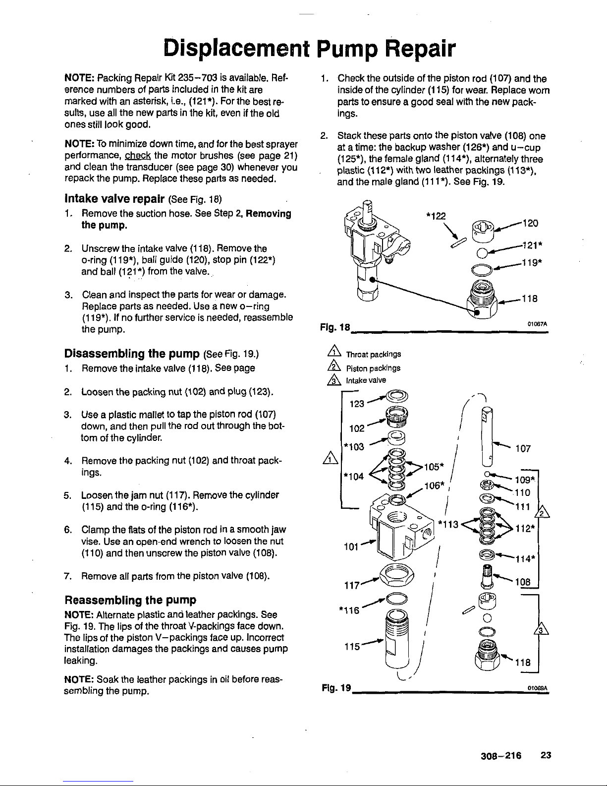
Displacem
nt
Pump
Repair
NOTE: Packing Repair Kit
235-703
is available. Ref-
erence numbers of parts included in the kit are
sults, use all the new parts in the kit, even if the old
marked with an asterisk, Le.,
(121*).
Forthe best re-
ones still look good.
NOTE:
To
minimize down time, and for the best sprayer
and clean the transducer (see page
30)
whenever you
performance, the motor brushes (see page
21)
repack the pump. Replace these parts as needed.
Intake
valve
repair
(See Fig.
18)
1.
Remove the suction hose. See Step
2,
Removing
the
pump.
2.
Unscrew the intake valve
(1 18).
Remove the
O-ring
(119*),
ball guide
(120),
stop pin
(122*)
and ball
(121*)
from the valve.,.
.
..
3.
Clean and inspect the parts for wear or damage.
Replace parts as needed. Use a new O-ring
(1
19*).
If no further service is needed, reassemble
the pump.
Disassembling the pump
(See Fig.
19.)
1.
Remove the intake valve
(1
18).
See page
2.
Loosen the packing
nut
(102)
and
plug
(123).
3.
Use a plastic mallet to tap the piston rod
(107)
tom of the cylinder.
down,
and then pull the rod out through the bot-
4.
Remove the packing nut
(102)
and throat pack-
ings.
5.
Loosen the jam nut
(1 17).
Remove the cylinder
(115)
and the O-ring
(116*).
6.
Clamp the flats of the piston rod in a smooth jaw
vise. Use an open-end wrench to loosen the nut
(1
10)
and then unscrew the piston valve
(108).
7.
Remove all parts from the piston valve
(108).
Reassembling the pump
NOTE Alternate plastic and leather packings. See
The lips of the piston V-packings face up. Incorrect
Fig.
19.
The lips of the throat V-packings face down.
leaking.
installation damages the packings and causes pump
sembling the pump,
NOTE: Soak the leather packings in oil before reas-
1.
Check the outside of the piston rod
(107)
and the
inside of the cylinder
(1
15)
for wear. Replace worn
parts to ensure a good seal with the new packings.
2.
Stack these parts onto the piston valve
(108)
one
at a time: the backup washer
(126*)
and u-cup
plastic
(112*)
with
Wo
leather packings
(1
13*),
(125*),
the female gland
(114*),
alternately three
and the male gland
(11
l*).
See Fig.
19.
A
Throat packings
A
Piston packings
A
Intake valve
Fig.
19
01069A
308-216
23
Page 24
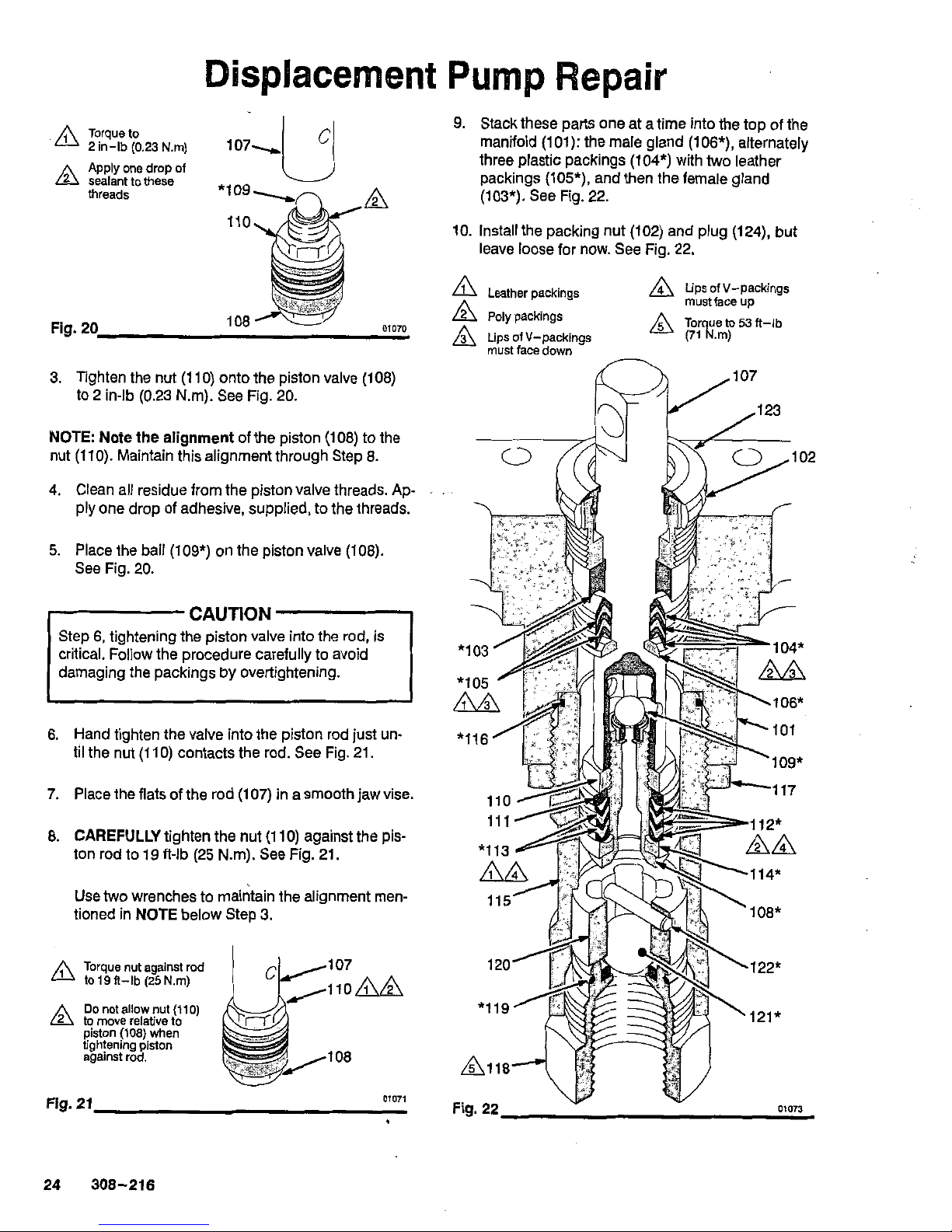
Displacement
Torque to
'A
2in-lb(0.23N.m)
107-
A
Apply one drop of
sealant to these
U
threads
Iro',X
A
"trim
3.
Tighten the nut
(110)
onto the piston valve
(108)
to 2 in-lb
(0.23
Nm). See Fig.
20.
NOTE: Note the
alignment
of the piston
(108)
to the
nut
(110).
Maintain this alignment through Step
8.
4.
Clean all residue from the piston valve threads.
Ap-
ply one drop of adhesive, supplied, to the threads.
5.
Place the ball
(log*)
on the piston valve
(108).
See Fig.
20.
CAUTION
critical. Follow the procedure carefully to avoid
Step
6,
tightening the piston valve into the
rod,
is
damaging the packings by overtightening.
6.
Hand tighten the valve into the piston rod just un-
til the nut
(110)
contacts the rod. See Fig.
21.
7.
Place the flats
of
the rod
(1
07)
in a smooth jaw vise.
8.
CAREFULLY
tighten the nut
(1 10)
against the pis-
ton rod
to
19
Alb
(25
Nm). See Fig.
21.
Use
two
wrenches to maintain the alignment men-
tioned in
NOTE
below Step
3.
A
to
19
I?-lb
(25
Nm)
Torque nut against rod
Do
not allow
nut
(1
io)
2
to move relative to
piston
(108)
when
tightening piston
against rod.
107
IlOAA
108
Fig.
21
01071
9.
Stack these parts one at a time into the top of the
manifold
(101):
the male gland
(106*),
alternately
three plastic packings
(104*)
with
two
leather
packings
(105*),
and then the female gland
(103*).
See Fig.
22.
10.
Install the packing nut
(102)
and plug
(124),
but
leave loose for now. See Fig.
22.
A
Leather packings
A
tips of V-packings
A
Poly
packings
A
Lips ofV-packings
must face up
A
Tor ue to
53
ft-ib
nust face down
(71R.rn)
24 308-216
Page 25
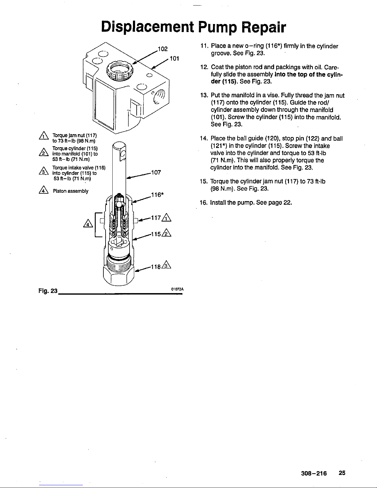
Displacement Pump Repair
A
into manifold
(101)
to
Torque cylinder
(1
15)
53ft-lb
(71
N.m)
Torque intake valve
(I
16)
A
into cylinder
(115)
to
53ft-lb
(71
N.m)
A
Piston assembly
11.
Place a new O-ring
(1
16*)
firmly in the cylinder
groove. See Fig.
23.
12.
Coat the piston rod and packings with oil. Carefully slide the assembly into
the
top of
the cylin-
der
(1
15).
See Fig.
23.
13.
Put the manifold in a vise. Fully thread the jam nut
(1
17)
onto the cylinder
(1
15).
Guide the rod/
cylinder assembly down through the manifold
(101).
Screw the cylinder
(1
15)
into the manifold.
See Fig.
23.
14.
Place the ball guide
(120),
stop
pin
(122)
and ball
(121*)
in the cylinder
(1
15).
Screw the intake
valve into the cylinder and torque to
53
ft-lb
(71
Nm). This will also properly torque the
cylinder into the manifold. See Fig.
23.
15.
Torque the cylinder jam nut
(1
17)
to
73
ft-lb
(98
Nm). See Fig.
23.
16.
Install the pump. See page
22.
Fig.
23
01072A
308-216 25
Page 26
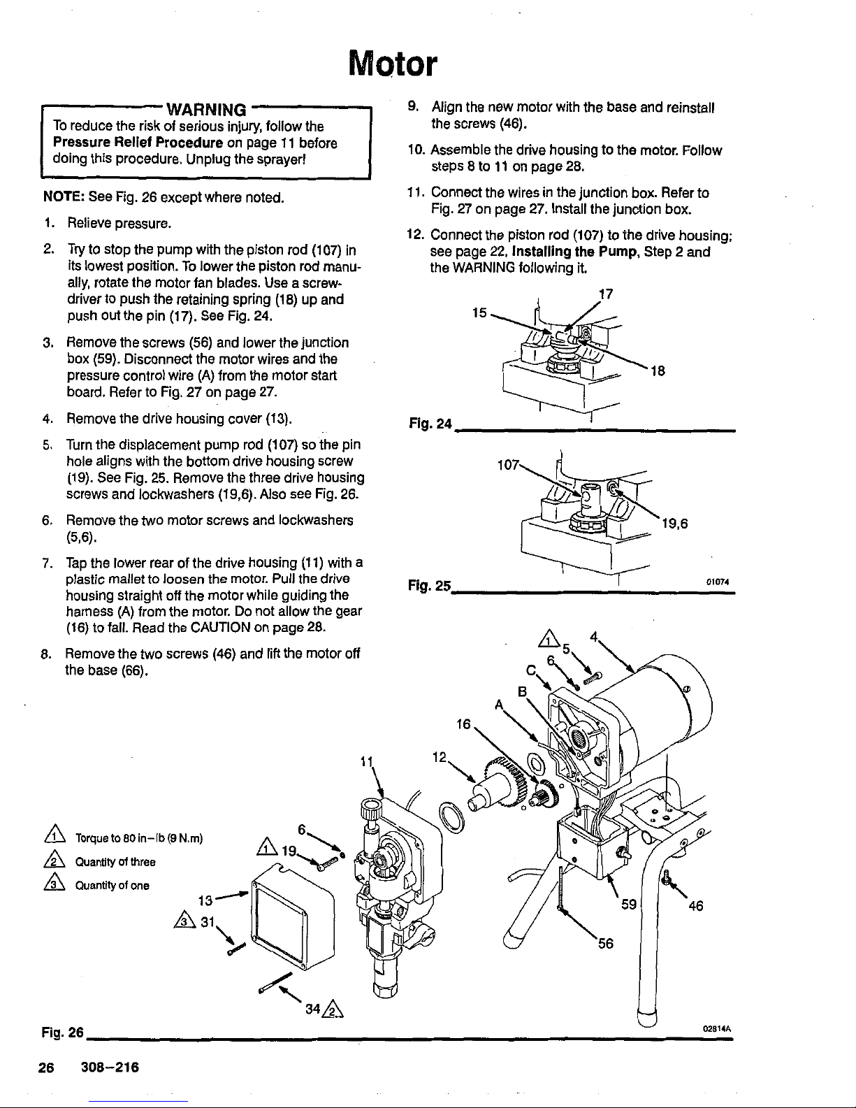
9.
Align the new motor with the base and reinstall
10.
Assemble the drive housing to the motor. Follow
the screws
(46).
steps 8 to
11
on page
28.
1.
2.
3.
4.
5.
6,
7.
6.
NOTE
See Fig.
26
except where noted,
,
Relieve
oressure.
~ ~
TI)'
to
stop the pump with the piston rod
(107)
in
its
lowest position. To lower the piston rod manually, rotate the motor fan blades. Use a screwdriver
to
push the retaining spring
(1
8)
up and
push out the pin
(17).
See
Fig.
24.
Remove the screws
(56)
and lower the junction
pressure control wire (A) from the motor start
box
(59).
Disconnect the motor wires and the
board. Refer to Fig.
27
on page
27.
Remove the drive housing cover
(13).
Turn the displacement pump rod
(107)
so
the pin
hole aligns with the bottom drive housing screw
screws and lockwashers
(19,6).
Also see Fig.
26.
(19).
See
Fig.
25.
Remove the three drive housing
Remove the
two
motor screws and lockwashers
(56).
Tap the lower rear of the drive housing
(1 1)
with a
housing straight
off
the motor while guiding the
plastic mallet
to
loosen
the
motor. Pull the drive
harness (A) from the motor.
Do
not allow the gear
(16)
to
fall. Read the CAUTION on page
26.
11.
Connect the wires in the junction box. Refer to
Fig.
27
on page
27.
Install the junction box.
12.
Connect the piston rod
(107)
to
the drive housing;
the WARNING following it.
see page
22,
Installing
the
Pump,
Step 2 and
17
15
.~
18
Fig.
24
1
107
19,6
Fig.
25
01074
h
Fig.
26
U
02814A
26
308-216
Page 27
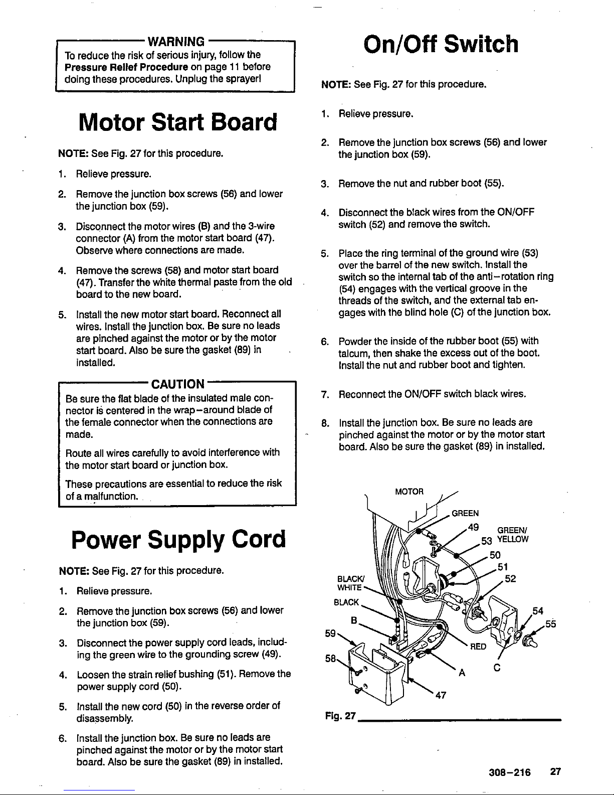
WARNING
To reduce the risk of serious injury, follow the
Pressure Relief Procedure
on page
11
before
doing these procedures. Unplug the sprayer1
Motor Start Board
NOTE
See
Fig.
27
for this procedure.
1.
Relieve pressure.
2.
Remove the junction box screws
(56)
and lower
the junction box
(59).
3. Disconnect the motor wires (B) and the 3-wire
connector
(A)
from the motor start board
(47).
Observe where connections are made.
4.
Remove the screws
(58)
and motor start board
board to the new
board.
(47).
Transfer the
white thermal paste from the old
5.
Install the new motor start board. Reconnect all
wires. Install the junction box. Be sure no leads
are pinched against the motor or by the motor
start board.
Also
be sure the gasket
(89)
in
installed.
CAUTION
Be
sure the flat blade of the insulated male connector is centered in the wrap-around blade of
the female connector when the connections are
made.
the motor start board or junction box.
Route all wires carefully to avoid interference with
These precautions are essential to reduce the risk
of a malfunction.
Power
Supply
Cord
NOTE See Fig.
27
for this procedure.
1.
Relieve pressure.
2.
Remove the junction box screws
(56)
and lower
3. Disconnect the power supply cord leads, includ-
the junction box
(59).
ing the green wire to the grounding screw
(49).
4.
Loosen the strain relief bushing
(51).
Remove the
power supply cord
(50).
5.
Install the new cord
(50)
in the reverse order of
disassembly.
6.
Install the junction box. Be sure no leads are
pinched against the motor or by the motor start
board.
Also
be sure the gasket
(89)
in
installed.
OnlOff
Switch
NOTE See Fig.
27
for this procedure.
1.
Relieve pressure.
2.
Remove the junction box screws
(56)
and lower
the junction box
(59).
3. Remove the nut and rubber boot
(55).
4.
Disconnect the black wires from the ON/OFF
switch
(52)
and remove the switch.
5.
Place the ring terminal of the ground wire
(53)
over the barrel
of
the new switch. Install the
switch
so
the internal tab of the anti-rotation ring
threads of the switch, and the external tab en-
(54)
engages with the vertical groove in the
gages with the blind hole
(C)
of the junction box.
6.
Powder the inside of the rubber boot
(55)
with
talcum, then shake the excess out of the boot.
Install the nut and rubber boot and tighten.
7.
Reconnect the ON/OFF switch black wires.
8.
Install the junction box. Be sure no leads are
pinched against the motor or by the motor start
board.
Also
be sure the gasket
(89)
in installed.
MOTOR
Fig.
27
308-216 27
Page 28
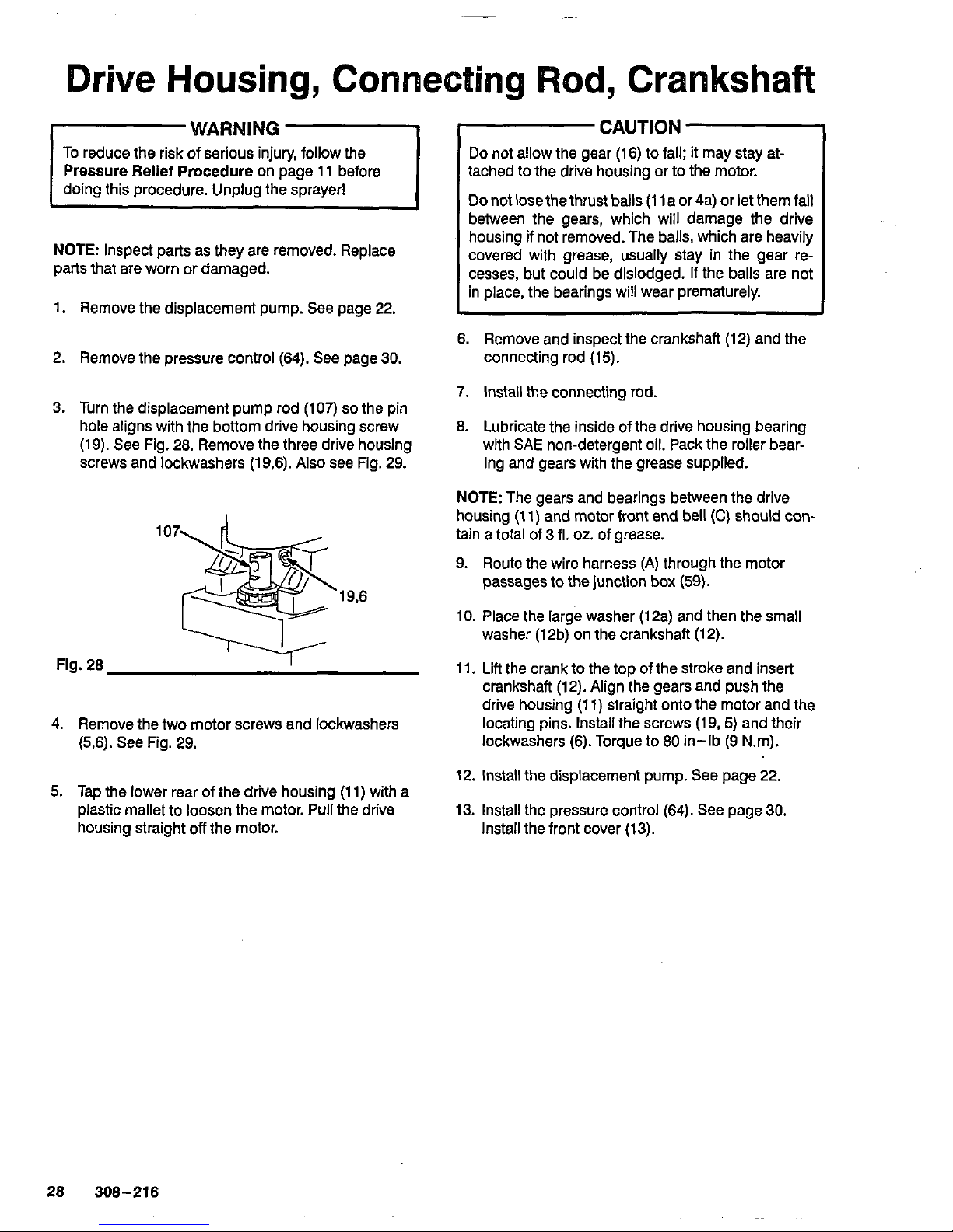
Drive
Housing,
Connecting
Rod,
Crankshaft
WARNING
To reduce the risk of serious injury, follow the
Pressure Relief
Procedure
on page
11
before
NOTE:
Inspect parts as they are removed. Replace
parts that are worn or damaged.
1.
Remove the displacement pump.
See
page 22.
2. Remove the pressure control
(64).
See
page
30.
3.
Turn the displacement pump rod
(107)
so
the pin
hole aligns with the bottom drive housing screw
(19). See Fig. 28. Remove the three drive housing
screws and lockwashers (19,6). Also
see
Fig. 29.
107
19,6
4.
Remove the two motor screws and lockwashers
(5,6).
See Fig. 29.
5.
Tap the lower rear of the drive housing
(1 1)
with a
housing straight
off
the motor.
plastic mallet to loosen the motor. Pull the drive
CAUTION
Do
not allow the gear
(16)
to fall: it may stay at-
tached to the drive housing or
to
the motor.
Do
not lose the thrust balls
(1
1
a
or
4a) or let them fall
between the gears, which will damage the drive
housing if not removed. The balls, which are heavily
covered with grease, usually stay in the gear re-
cesses, but could be dislodged.
If
the balls are not
in place, the bearings will wear prematurely.
6.
Remove and inspect the crankshaft (12) and the
connecting rod
(15).
7.
Install the connecting rod.
8.
Lubricate the inside of the drive housing bearing
with SA€ non-detergent oil. Pack the roller bear-
ing and gears with the grease supplied.
housing
(1 1)
and motor front end bell
(C)
should con-
NOTE:
The gears and bearings between the drive
tain a total of
3
11.0~.
of
grease.
9.
Route the wire harness (A) through the motor
passages to the junction box
(59).
10.
Place the large washer
(12a)
and then the small
washer
(12b)
on the crankshaft (12).
11.
Lift the crank to the top of the stroke and insert
drive housing
(1
1) straight onto the motor and the
crankshaft (12). Align the gears and push the
lockwashers
(6).
Torque to 80 in-lb (9 Nm).
locating pins. lnstaii the screws (19.
5)
and their
12. Install the displacement pump. See page
22.
13. Install the pressure control (64).
See
page
30.
Install the front cover
(13).
28
308-216
Page 29
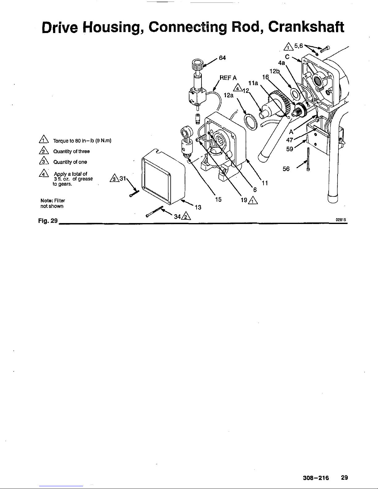
Drive
Housing,
Connec
od,
Crankshaft
A
Torque to
80
in-lb
(9
N.m)
A
Quantity
of
three
A
Quantity
of
one
A
~pp~y
a total
of
3
fl.
oz.
of
grease
A31
to gears.
Note:
Filter
not shown
Fig.
29
308-216
29
Page 30
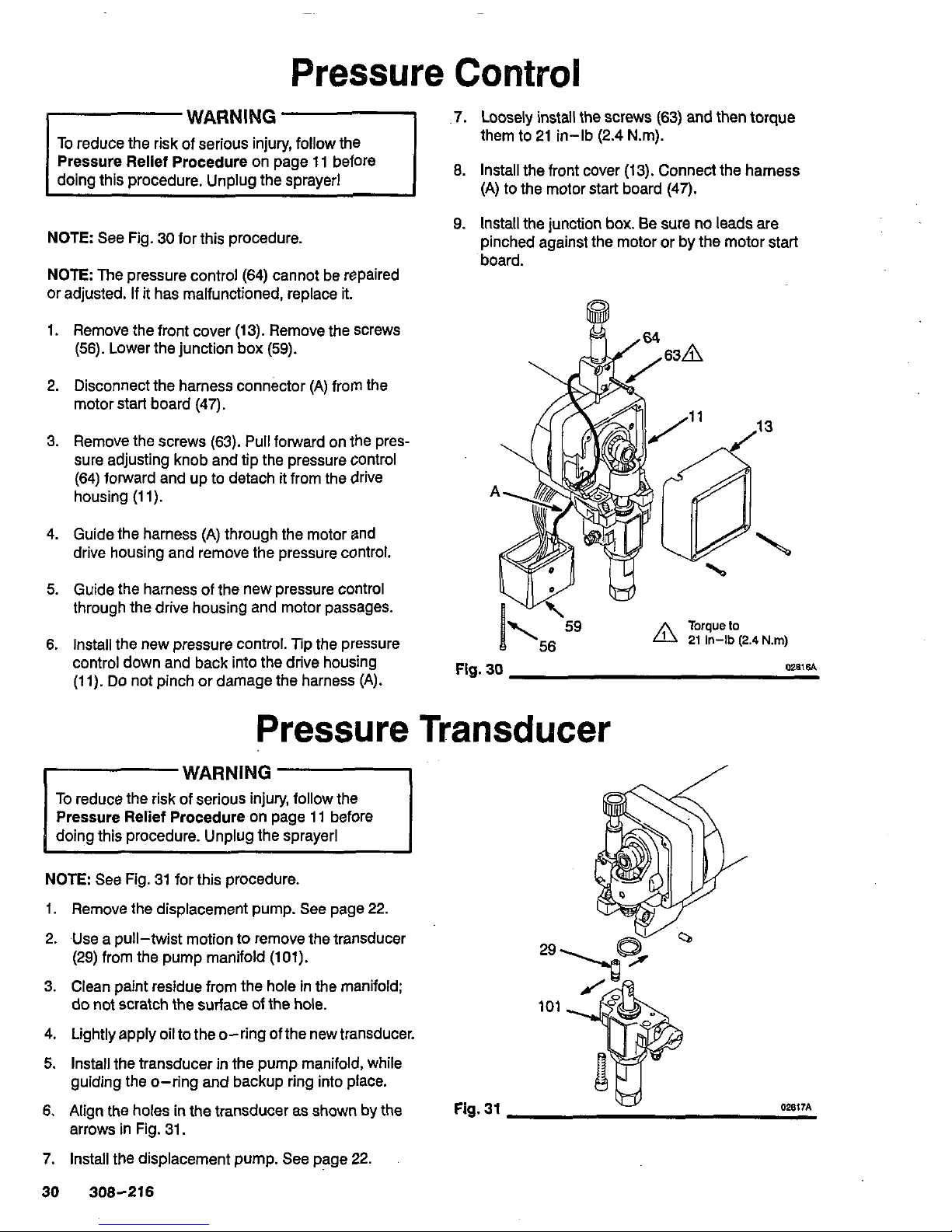
Pressure
Control
WARNING
To reduce the risk of serious injury, follow the
NOTE:
See Fig.
30
for this procedure.
or adjusted. If it has malfunctioned, replace it.
NOTE:
The pressure control
(64)
cannot be repaired
1.
Remove thefront cover
(13).
Remove the screws
(56).
Lower the junction box
(59).
2.
Disconnect the harness connector (A) from the
motor start board
(47).
3.
Remove the screws
(63).
Pull fotward on the pres-
sure adjusting knob and tip the pressure control
(64)
fotward and
up
to detach it from the drive
housing
(1 1).
4.
Guide the harness (A) through the motor and
drive housing and remove the pressure control.
5.
Guide the harness
of
the new pressure control
through the drive housing and motor passages.
6.
Install the new pressure control. Tip the pressure
control down and back into the drive housing
(1
1).
Do
not pinch or damage the harness (A).
7.
Loosely install the screws
(63)
and then torque
them to
21
in-lb
(2.4
Nm).
8.
Install the front cover
(13).
Connect the harness
(A) to the motor start board
(47).
9.
Install the junction box. Be sure no leads are
board.
pinched against the motor or by the motor start
Pressure Transducer
WARNING
To reduce the risk of serious injury, follow the
Pressure Relief Procedure
on page
11
before
NOTE:
See Fig.
31
for this procedure.
1.
Remove the displacement pump. See page
22.
2.
Use a pull-twist motion to remove the transducer
(29)
from the pump manifold
(101).
do not scratch the surface of the hole.
3.
Clean paint residue from the hole in the manifold;
4.
Lightly apply oil to the O-ring of the new transducer.
5.
Install the transducer
in
the pump manifold, while
guiding the O-ring and backup ring into place.
6.
Align the holes
in
the transducer as shown by the
arrows in Fig.
31.
7.
Install the displacement pump. See page
22.
30 308-216
Fig.
31
29
101
02817A
Page 31
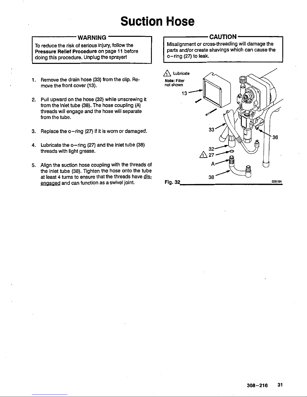
Suction
Hose
WARNING
-1
CAUTION
1
To
reduce the risk of serious injury, follow the
Misalignment or cross-threading will damage the
Pressure Rellef Procedure on page
11
before
parts and/or create shavings which can cause the
doing this procedure. Unplug the sprayer1
o-ring
(27)
to leak.
1.
2.
3.
4.
5.
Remove the drain hose
(33)
from the clip. Re-
move the front cover
(13).
Pull
upward on the hose
(32)
while unscrewing it
from the inlet tube
(38).
The hose coupling
(A)
threads will engage and the hose will separate
from the tube.
Replace the o-ring
(27)
if
it
is worn or damaged.
Lubricate the o-ring
(27)
and the inlet tube
(38)
threads with light grease.
Align the suction hose coupling with the threads of
the inlet tube
(38).
Tighten the hose onto the tube
at least
4
turns to ensure that the threads have
dk-
enaaaed and can function as a swivel joint.
Note:
Filter
not
shown
308-216 31
Page 32
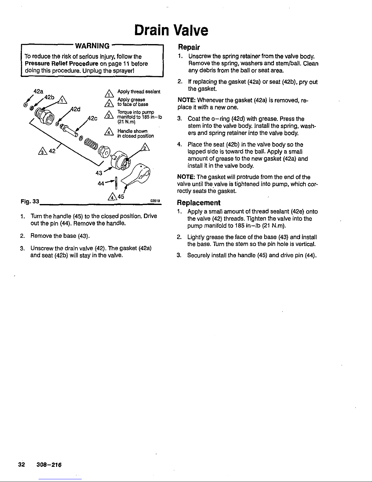
Drain
Valve
WARNING
To reduce the risk
of
serious injury, follow the
42a
A
Apply
thread
sealant
Fig.
33
02818
1. Turn the handle (45) to the closed position. Drive
out the pin (44). Remove the handle.
2.
Remove the base (43).
3.
Unscrew the drain valve
(42).
The gasket (42a)
and seat (42b) will stay in the valve.
Repair
1. Unscrew the spring retainer from the valve body.
Remove the spring, washers and stemlball. Clean
any debris from the ball
or
seat area.
2.
If
replacing the gasket (42a) or seat (42b), pry out
the gasket.
NOTE:
Whenever the gasket (42a) is removed, re-
place it with a new one.
3.
Coat the O-ring (42d) with grease. Press the
stem into the valve body. Install the spring, washers and spring retainer into the valve body.
4.
Place the seat (42b)
in
the valve body
so
the
lapped side is toward the ball. Apply a small
amount of grease to the new gasket (42a) and
install it in the valve body.
NOTE
The gasket will protrude from the end of the
valve until the valve is tightened into pump, which correctly seats the gasket.
Replacement
1. Apply a small amount
of
thread sealant (42e) onto
the valve (42) threads. Tighten the valve into the
pump manifold to 185 in-lb (21 Nm).
2. Lightly grease the face of the base (43) and install
the base. Turn the stem
so
the pin hole
is
vertical.
3.
Securely install the handle (45) and drive pin (44).
32
308-216
Page 33
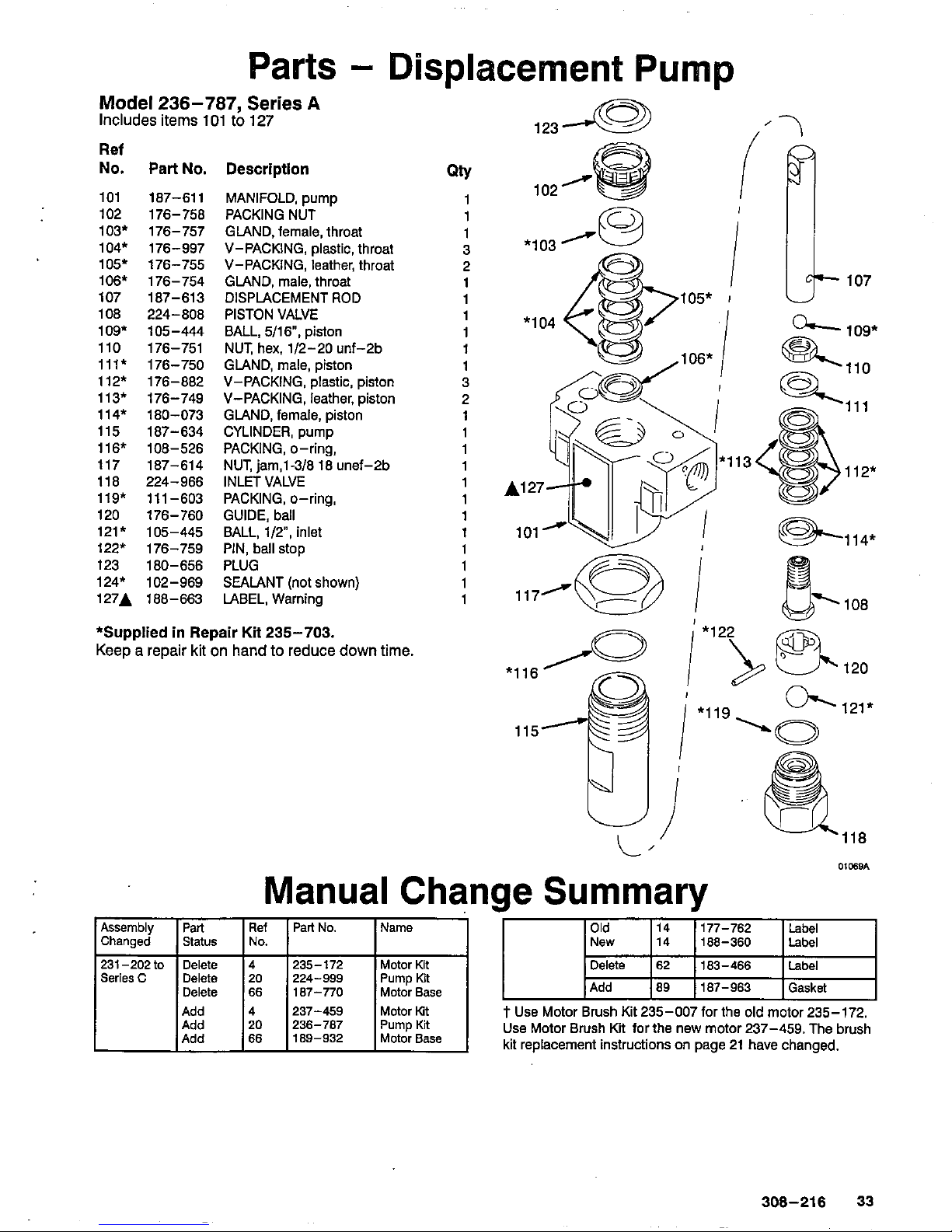
Parts
-
Displacement Pump
Model
236-787,
Series
A
Includes
items
101
to
127
Ref
No.
Part
No.
101 187-611
102
176-758
103*
176-757
104*
176-997
105'
176-755
106*
176-754
107
187-613
108
224-808
109*
105-444
110
176-751
112*
176-882
111'
176-750
113*
176-749
114*
180-073
115
187-634
116*
108-526
117 187-614
118
224-966
119* 111-603
120
176-760
121*
105-445
122*
176-759
124*
102-969
123 180-656
127A
188-663
Description
PACKING NUT
MANIFOLD, pump
V-PACKING, plastic, throat
GLAND, female, throat
V-PACKING, leather, throat
GLAND, male, throat
DISPLACEMENT ROD
PISTON VALVE
BALL,
5/16,
piston
NUT, hex,
1/2-20
unf-2b
GLAND, male, piston
V-PACKING, plastic, piston
V-PACKING, leather, piston
GLAND, female, piston
CYLINDER, pump
PACKING, O-ring,
NUT,
jam,l-3/8
18
unef-2b
INLET VALVE
GUIDE, ball
PACKING, O-ring,
PIN, ball stop
BALL,
1/2",
inlet
PLUG
SEALANT (not shown)
LABEL, Warning
*Supplied in Repair Kit
235-703.
Keep a repair
kit
on
hand
to
reduce
down
time.
Qty
1
1
1
3
2
1
1
1
1
1
1
2
3
1
1
1
1
1
1
1
1
1
1
1
1
123
I
102
/
i
*lo3
*lo4
I
'I
I
I
*1
;c
107
13
&114*
117/a
108
Manual Change Summary
.-
Assembly
Add 187-963
Gasket
Motor
Base
187-770
66
Delete
Delete
183-466
Label
Motor
Kit
235-172
Pump
Kit
224-999
20
Delete
SeriesC
4
Delete
231-202
to
Ref
Part No. Name
/
No. Status
Changed
Part
Add
4
237-459
Motor Kit
t
Use Motor Brush Kit
235-007
for the
old
motor
235-172.
Add
Add
20
236-787
PumpKR
Use Motor Brush Kit for the new motor
237-459.
The brush
66
189-932
Motor
Base
kit replacement instructions
on
page
21
have changed.
308-216
33
PTFE
PTFE
PTFE
PTFE
PTFE
PTFE
Page 34
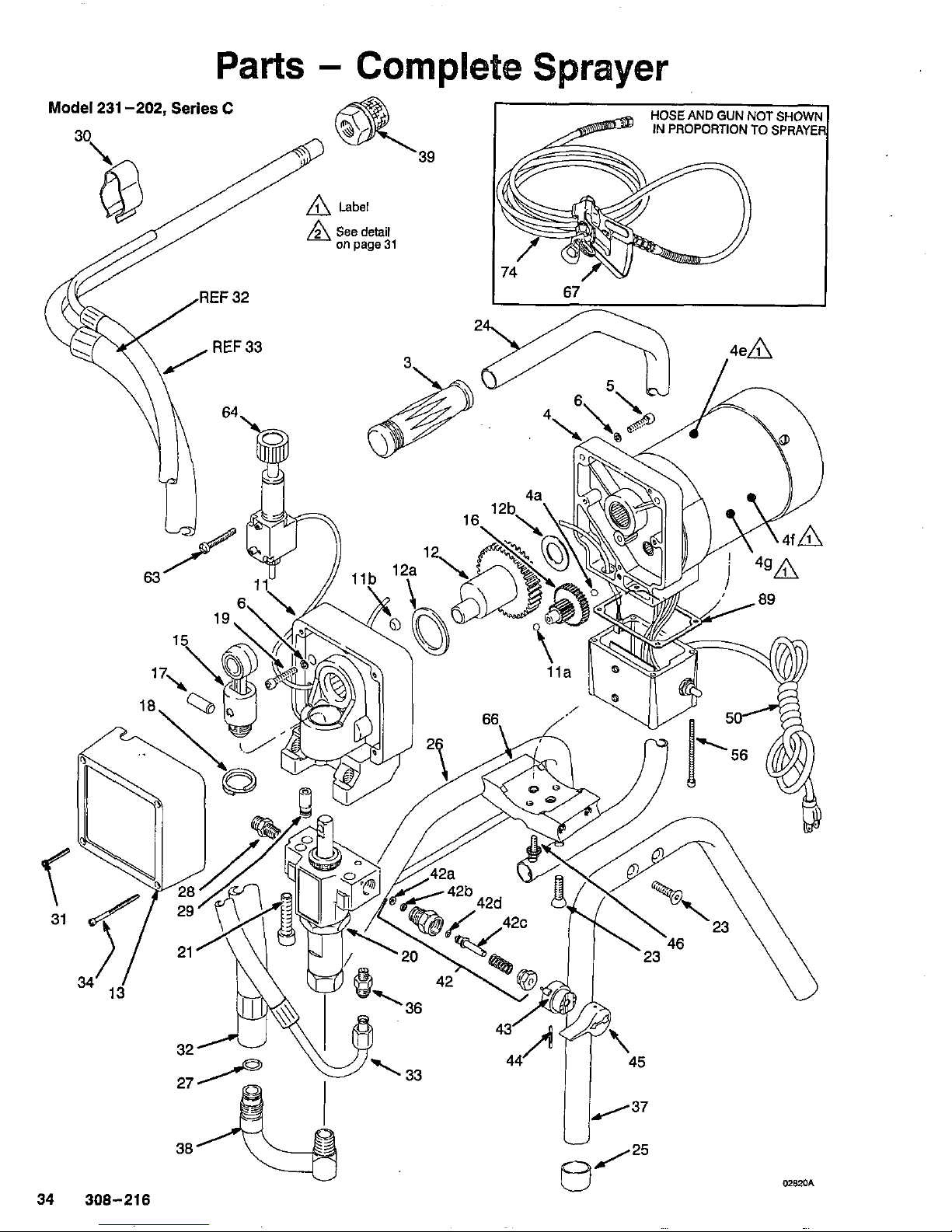
U
ptJ25
34
308-216
u
Page 35
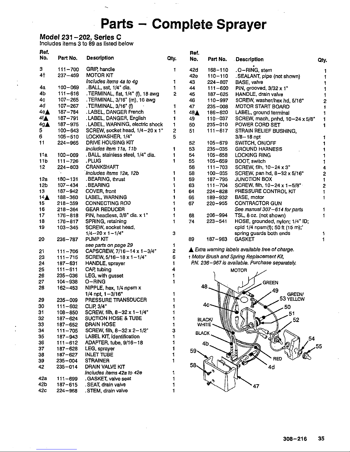
Parts
-
Complete
Sprayer
Model
231
-202,
Series
C
Includes
items 3 to
89
as
listed
below
Ret.
No.
Part
No.
Descrlptlon
Ref.
QW.
No.
Part
No.
.Descrlptlon
QW.
3
11
1-700 GRIP, handle
1
42d 168-110
.O-RING,stem
4t 237-459 MOTORKIT 428 110-110 .SEALANT, pipe (notshown)
1
1
4a 100-069 .BALL, sst, 1/4" dia. 1 44 11 1-600 PIN, grooved, 3/32 x 1"
1
4b 11 1-616 .TERMINAL, flat, 1/4" (9,18 awg 2 45 187-625 HANDLE, drain valve
1
4c 107-265 .TERMINAL, 3/16"
(m),
16 awg 46 110-997 SCREW, washer/hex hd, 5/16"
1
2
4eA 187-784 .LABEL. DANGER French 1
48A
186-620 LABEL, ground terminal
1
4fA 187-791 .LABEL, DANGER, English
1
1
49 110-037 SCREW, mach, pnhd, 10-24 x
5/8"
1
4gA 187-975 .LABEL, WARNING, electricshock 1
5
100-643
SCREW,
socket head, 1/4-20
X
1"
2 51 111-617 STRAIN RELIEF BUSHING,
1
6 105-510 LOCKWASHER, 1/4"
5
3/8-18 npt
11
224-965 DRIVE HOUSING KIT
1
1
lla 100-069 .BALL, stainless
Steel,
1/4" dia. 1 54 105-658 LOCKING RING
1
llb 111-726 .PLUG 1 55 105-659 BOOT, switch
1
12 224-803 CRANKSHAFT 56 11 1-703 SCREW, filh, 10-24
X
3"
1
'Includes items 12a. 126 1
58
100-035 SCREW, pan hd, 8-32~ 5/16"
4
12a 180-131 .BEARING, thrust 1 59 187-795 JUNCTION BOX
2
12b 107-434 .BEARING
1
1
13 187-942 COVER, front 1 64 224-828 PRESSURE CONTROL KIT
63 111-704
SCREW,filh.10-24~1-5/8".
2
14A 188-360 LABEL, WARNING
1
1
66 189-932 BASE, motor
15 218-359 CONNECTING ROD 1 67 220-955 CONTRACTOR GUN
1
16 218-364 GEAR REDUCER 1 See rnanual307-614 forparts
17 176-818 PIN, headless, 3/8" dia. x
1"
1
68 206-994 TSL,
8
02.
(not shown)
1
18
176-817 SPRING, retaining 1 74 223-541 HOSE, grounded, nylon; 114" ID;
1
19 103-345 SCREW, socket head,
20
236-787 PUMP KIT 89 187-963 GASKET
21 111-706 CAPSCREW,7/16-14x1-3/4"
2
A
€&a
warning labels available free of charge.
23 111-715 SCREW,5/16-18x1-1/4" 6
t
Motor Brush and Spring Replacement
Kit,
Includes items
4a
to 49
1
43 224-807 BASE. valve
4d 107-267 .TERMINAL, 3/16"
(f)
1
47
235-008
MOTOR STARTBOARD
50
235-010 POWER CORD
SET
52 105-679 SWITCH, ON/OFF
Includes item
1
la,
1
lb
1
53 235-035 GROUND HARNESS
1/4-20
X
1-114"
3
cpld 114 npsm(f):
50ft
(15
m);'
spring guards both ends 1
1
seepartsonpage29 1
24 187-631 HANDLE, sprayer 1
25
11
1-61 1
CAP, tubing
PN.
236-967is available. Purchase separately.
26 235-036 LEG, with gusset
28 162-453 NIPPLE, hex, 1/4 npsm x
27 104-938 O-RING
29 235-009 PRESSURE TRANSDUCER
30
111-602 CLIP, 3/4"
31 108-850
SCREW,
filh.
8-32 x 1 -1/4"
32 187-624 SUCTION HOSE
8
TUBE
33 187-652 DRAIN HOSE
35 187-943 LABEL KIT, identification
34 111 -705
SCREW,
filh,
8-32 X 2-112"
36 111-612
ADAPTER, tube, 9/16-18
37 187-628 LEG, sprayer
55
38 187-627 INLETTUBE
39 235-004 STRAINER
42 235-014 DRAIN VALVE KIT
1/4 npt. 1-3/16"
Includes items 42s
to
4%
4Za 11 1-699 .GASKET, valve seat
42b 187-615
.SEAT, drain valve
42c 224-968
.STEM, drain valve
308-216
35
Page 36
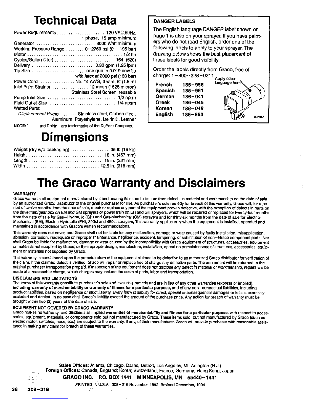
Technical Data
Power
Requirements,,
...................
120
VAC,GOHz,
Generator
3000 Watt
minimum
1 phase, 15 amp minimum
Working
Pressure
Range
........
0-2750
psi
(0
-
195 bar)
Motor
..........................................
112
hp
CycleslGallon (iiter)
..........................
164
(620)
Delivery
...........................
0.33 gpm (1.25 Ipm)
Tip Size
.......................
one
gun
to
0.019
new
tip
with
latex at 2000
psi
(1
38 bar)
Power Cord
...............
No.
14
AWG, 3 wire, 6 (1.8
m)
Inlet
Paint Strainer
................
12
mesh
(1525
micron)
Pump
Inlet
Size 112 npt(f)
Stainless
Steel
Screen, reusable
Wetted Parts:
Fluid
Outlet
Size
114
npsm
Displacement
Pump
.......
Stainless steel, Carbon
steel,
Aluminum,
Polyethylene,
Delrinw,
Leather
..........................
..............................
.............................
NOTE and Delrin are trademarks
01
the DuPont Company.
Dimensions
Weight
(dry
wlo
packaging)
................
35
Ib
(18 kg)
Height
................................
18
in.
(457
mm)
Length
................................
15
in.
(381 mm)
Width
................................
12.5
in.
(318 mm)
DANGER LABELS
The
English
language
DANGER
label
shown
on
page
1
is
also
on
your sprayer.
If
you
have
paint-
ers
who
do
not
read
English,
order
one
of
the
following
labels
to
apply
to
your
sprayer.
The
these
labels
for
good
visibility.
drawing
below
shows
the
best
placement
of
Order
the
labels
directly
from
Graco,
free
of
charge:
1-800-328-0211
Applyother
French 185-956
language
her
Spanish 185-961
German 186-041
Korean
186-049
Greek 186-045
English
185-953
The
Graco Warranty and
Disclaimers
WARRANN
Graco warrants all equipment manufactured by it and bearing its name to be free from defects in material and workmanship
on
the date
01
sale
by an authorized Graco distributor
to
the original purchaser for use.
As
purchaser's sole remedy for breach of this warranty, Graco wlii. for a pe-
the drive traiwgear box
on
EM
and
GM sprayers
ar
power train on EH
and GH sprayers,
which will be repaired or
replaced for twenty-four months
riod of twelve months from
the date of sale, repair or replace any part
01
the equipment
proven
defective, with the exception of defects In parts on
from the date of sale lor Gas-Hydraulic (GH) and Gas-Mechanical (GM) sprayers and for thirty-six months from the date of sale for Electric.
Mechanical (EM), Electric-Hydraulic (EH), 390st and 490st sprayers, This warranty applies only when the equipment is installed, operated and
maintained in accordance with Graco's written recommendations.
This warranty does not cover, and Graco shall not be liable lor, any mallunction, damage or wear caused by faulty installation, misapplication,
abrasion, corrosion, inadequate or improper maintenance, negligence. accident. tampering. or substitution
of
non-Graco component parts. Nor
shall Graco be liable for malfunction, damage or wear caused by the incompatibility
with
Graco equipment of structures, accessories, equipment
or materials not supplied by Graco, or the improper design, manufacture. installation, operation or maintenance of structures, accessories, equipment or materials not supplied by Graco.
This warranty is conditioned upon the prepaid return olthe equipment claimed to be defective to an authorized Graco distributor lor verification
of
the Claim. If the claimed defect is verified, Graco will repair or replace free
01
charge any defective parts. The equipment will be returned to the
original purchaser transportation prepaid.
If
inspection of
the
equipment does not disclose any defect
in
material or workmanship, repairs will
be
made at a reasonable charge, which charges may include the costs of parts, labor and transportation.
DISCLAIMERS AND LlMiTATlONS
The terms
of
this warranty constitute purchaser's
sole
and exclusive remedy and are in lieu of any other warranties (express or implied),
including warranty
of
merchantabillly
or
warranty of fitness for a particular purpose, and of any non-contractual liabilities, including
product liabilities. based on negligence or strict iiabliity. Every form of iiablilty for direct, special or consequential damages
or
ioss Is expressly
excluded and denied. In no case shall Graco's liability exceed the amount
of
the purchase price. Any action lor breach of warranty must be
brought within two
(2)
years
of
the date of sale.
Graco makes no warranty, and disclaims ail implied warranties of merchantablllty and fitness for
a
particular purpose. with respect to acces-
EQUIPMENT NOT COVERED
BY
GRACO WARRANN
SOrieS,
equipment, materiais, or components sold but not manufactured by Graco. These Bems soid, but not manufactured by Graco (such as
electric motor, switches, hose, etc.) are subject to the warranty, if any, of their manufacturer. Graco will provide purchaser with reasonable assistance in making any claim for breach
01
these warranties.
Sales
Offlces: Atlanta, Chicago, Dallas, Detroit, Los Angeles, Mt. Arlington
(N.J.)
Foreign
Offlces:
Canada;
England;
Korea;
Switzerland;
France;
Germany;
Hong
Kong;
Japan
..
1;
r.
.:
:
GRACO INC.
EO.
BOX
1441 MINNEAPOLIS, MN 55440-1441
36
308-216
PRlNTED.1NU.S.A.
308-216
November, 1992, Revised December,
1994
..
PTFEPTFEPTFE
 Loading...