

Graco PRO 224-094, PRO 224-224, PRO 235893, PRO 235-894, PRO 308-084 Instructions Manual
...Page 1

I
NSTRUCTIONS–PARTS
This
manual contains IMPORT
ARNINGS AND INSTRUCTIONS
W
READ AND RET
AIN FOR REFERENCE
ANT
LIST
308–084
Rev. H
Supersedes
G
Model
PRO 4600SC
AUTOMATIC ELECTROSTATIC
AIR SPRA
100
psi (7 bar) MAXIMUM WORKING PRESSURE
U.S.
Patent No. 4,290,091; 4,219,865; 4,497,447; 4,462,061; 4,660,774;
5,063,350; 5,073,709; 5,080,289; 5,093,625
Patented 1986, 1987 Canada
Brevete 1986, 1987
U.K. Patent No. 2,147,158; 2,142,559B; 2,140,327B; 2,245,197B
French Patent No. 91 14488
Other Foreign Patents Pending
Part No. 224–224, Series A
Air Spray Gun, without shroud
(0.059 in. (1.5 mm) spray nozzle)
Part No. 235–893, Series A
Air Spray Gun, with standard shroud
Y GUN
0432
Part No. 235–894, Series A
Air Spray Gun, with slotted shroud
For
use when the gun is mounted in
the front position; see Fig 3 , page 6
Part No. 224–094 Series A
Gun Manifold
Must
order separately
For use with Class
.
, Group D paint spray materials
0435
Part
No. 235–893 shown
GRACO INC. P.O. BOX 1441 MINNEAPOLIS, MN 55440–1441
COPYRIGHT
1991 GRACO INC.
Page 2

WARNINGS
SERIOUS BODILY INJUR Y, EXPLOSION, FIRE, OR ELECTROST ATIC SHOCK CAN
OCCUR IF THE PRECAUTIONS BELOW ARE NOT FOLLOWED.
READ AND UNDERSTAND ALL INSTRUCTION MANUALS, T AGS, AND WARNING
LABELS BEFORE OPERATING EQUIPMENT.
ELECTROSTATIC EQUIPMENT SHALL ONLY BE USED BY TRAINED, QUALIFIED
PERSONNEL WHO SHALL BE FULL Y CONVERSANT WITH THE REQUIREMENTS
STATED WITHIN THIS INSTRUCTION MANUAL.
EQUIPMENT MISUSE HAZARD
General
Any misuse of the spray equipment or accessories, such as
over pressurizing, modifying parts, using incompatible chemicals and fluids, or using worn or damaged parts, can cause
them
or
NEVER
NEVER
ALWAYS
cleaning or removing the fluid nozzle or servicing any system
equipment.
NEVER
NEVER alter or modify any part of this equipment; doing so
could
CHECK all spray equipment regularly and repair or replace
worn
System
This
psi
gun
HAZARDOUS
Improper handling of hazardous fluids or inhaling vapors can
cause extremely serious bodily injury , even death, due to
splashing in the eyes, ingestion, inhalation, or bodily contamination. Be sure you know what fluid you are pumping and its
specific hazards. Observe all precautions when handling
known
to,
1.
2. Dispose
Safety
to rupture and result in serious bodily injury
property damage.
point the spray gun at anyone or at any part of the body
put hand or fingers over the spray nozzle.
follow the
try to stop or deflect leaks with your hand or body
cause it to malfunction.
or damaged parts immediately
Pressure Relief Procedure
.
, fire, explosion
, at right, before
.
Pressure
gun has a maximum working air and fluid pressure of 100
(7 bar). Never exceed the maximum working pressure of the
or any other component or
accessory used in the system.
FLUID HAZARD
or potentially hazardous fluids, including, but not limited
the following precautions.
Store hazardous fluids in approved containers.
Federal
wastes.
of any waste fluid according to all Local, State and
regulations pertaining to the disposal of hazardous
Fluid
Compatibility
BE SURE all fluids and solvents used are chemically compatible with
Always
erature
Pressure
.
To
the
shock,
tem, when checking or
when installing, cleaning or changing fluid nozzles, and when
ever
1. Turn
2. Turn
3. Trigger the gun into a
4. Open
5. Leave the pump drain valve open until you are ready to
3.
4.
5. Provide proper ventilation in accordance with accepted
the “Wetted Parts” shown in the TECHNICAL DATA.
read and follow the
before using the fluid or solvent in this gun.
fluid and solvent manufacturer’s lit
Relief Procedure
reduce the risk of serious bodily injury
eyes or on the
always follow this procedure
you stop spraying.
of
air.
If the air pilot fluid regulator is
ed
at the regulator air inlet to relieve pressure in the fluid line.
of
relieve
the pump drain valve, having a waste container ready
to
catch the drainage.
spray
again.
Read and follow the fluid and solvent
ture
regarding the use of protective clothing and
such as eye
Provide for the safe piping and disposal of all exhaust air
industry
Ventilate
skin, injury from moving parts or electrostatic
servicing any part of the spray system,
f all the air to the control module
f the fluid supply to the gun.
fluid pressure.
protection, respiratory protection, and gloves.
standards and governmental regulations. Refer to
the Spray Booth
grounded
, on page 6.
, including splashing
when shutting of
except the manifold
used, air pressure is need
metal waste container to
manufacturer’s litera
in
f the sys
equipment,
-
-
-
-
-
.
HOSE SAFETY
TIGHTEN
NEVER
tire
movement of the hose couplings. If any of these conditions
exist,
all fluid connections securely before each use.
use a damaged hose. Before each use, check the en
hose for cuts,
replace the hose immediately
leaks, abrasion, bulging cover
.
, or damage or
HANDLE AND ROUTE HOSES CAREFULLY. Do not pull on
hoses
-
to move equipment. Do not use fluids or solvents which
are
not compatible with the inner tube and cover of the hose.
Page 3

FIRE, EXPLOSION, OR ELECTROSTA
TIC SHOCK HAZARD
To reduce the risk of fire, explosion, or electrostatic shock,
which
may result from electrical discharge, it is essential that:
S
All parts of the electrostatic system are properly grounded.
S All personnel in or close to the spray area are properly
grounded.
S All
electrically conductive objects or devices in the spray area,
including
grounded.
When operating the electrostatic device, any ungrounded
objects in the spray area (such as people, containers, tools,
etc.)
objects
cient energy levels can ignite the fluid being sprayed, fumes
from
This
sult
Static electricity can also be generated by the flow of fluid
through the pump, hose, gun, and nozzle, but it is dissipated
through
If
you experience any arcing or feel even a slight shock,
SPRAYING
entire
starting
paint containers, wash
can become electrically charged. Arcing may
then come in contact or close to ground. Arcing of suf
solvents, dust particles, and other flammable substances.
can cause a fire, explosion, or electrostatic
in serious bodily injury and property damage.
proper grounding as described in
IMMEDIA
system. Be sure you
to spray again.
TELY
cans and tools, are properly
occur if these
shock and re
Grounding
. Check for proper grounding of the
have corrected the problem before
below
STOP
Grounding
The
following are minimum requirements for grounding a basic
electrostatic
or objects which must also be grounded. Always check your
local
your
system is connected to a true earth ground.
1.
Pump:
described
2.
Air compressors and hydraulic power supplies:
according
3.
Electrostatic
nection
Graco Electrically Conductive Air Supply Hose; see
ACCESSORIES section to order . Connect the air hose
ground
4.
Object being sprayed:
and grounded at all times. Contact points must be sharp
points
5.
All electrically conductive objects or devices
area, including paint containers and wash cans, must be
properly
system. Y
electrical code for detailed grounding instructions. Be sure
ground by using a ground wire and clamp as
in your separate pump instruction manual.
to the manufacturer’s recommendations.
to a properly grounded air supply hose. Use only the
wire to a true earth ground.
or knife edges.
grounded.
our system may include other
Air Spray
Gun:
obtain grounding through con
keep the work piece hangers clean
equipment
ground
in the spray
6.
All
persons entering the spray area:
ductive
soles, such as leather
must
be worn. Rubber or plastic soles are not conductive.
7.
The floor of the spray area
grounded. Do not cover the floor with cardboard or any
and
non-conductive material which would interrupt grounding
continuity.
8.
Flammable liquids
approved,
quantity
9.
All solvent pails:
conductive. Do not place the pail on any non-conductive
fi-
-
surface,
grounding
10.
All air and fluid lines and electric cables
grounded.
grounded containers. Do not store more than
needed for one shift.
such as cardboard or paper
continuity
in the spray area must be kept in
use only grounded metal pails, which are
must be electrically conductive
.
shoes
, or personal grounding straps
must have con
the
, which would interrupt
must be properly
-
Flushing and Cleaning Safety
To
reduce the risk of static
.
the Pressure Relief Procedure
Be
sure the turbine air (electrostatics) is
ing
or cleaning any part of the spray system.
Use
the lowest possible pressure to flush. T
grounded
To
point
metal waste container
flush or purge
equal to or greater than that of the fluid being sprayed.
equipment,
To clean the exterior of the equipment,
with
a flash point of higher than 100_ F (38
ALWAYS
the
Use
hangers.
Ventilate
To
vapors,
Check
air exhaust velocity requirements. Check and follow all local
safety
NEVER operate the spray gun unless the ventilating fans are
operating.
remove all solvent from the system before reactivating
spray gun.
only non-sparking tools to clean residue from the booth and
the Spray Booth
prevent hazardous concentrations of toxic and/or
spray only in a properly ventilated spray booth.
and follow all National, State and Local codes regarding
and fire codes and OSHA standard 1910.107.
sparking or splashing, always follow
on page 2 before flushing.
OFF before flush
.
ALWA
YS use solvents with a flash
rigger the gun into
ALWAYS use solvents
_ C).
flammable
a
-
United
States Government safety standards have been adopted under the Occupational
General Standards, Part 1910.107 and any other appropriate regulations––should be consulted in connection with the installation, operation, and
maintenance of electrostatic spray painting equipment.
IMPORTANT
Safety and Health Act. These standards––particularly the
308-0843
Page 4

TABLE OF CONTENTS
Warnings 2.
Terms 4.
Installation
Typical
Warning
Ventilate
Install
Install
Install
Connect
Check
Install
Operation
Operating
Selecting
Gun
Activating
Adjusting
Adjusting
Activating
Maintenance
Daily
Clean
Check
. . . . . . . . . . . . . . . . . . . . . . . . . . . . . . . . . . . .
. . . . . . . . . . . . . . . . . . . . . . . . . . . . . . . . . . . . . . .
Installation5. . . . . . . . . . . . . . . . . . . . . . . . . . .
Signs5. . . . . . . . . . . . . . . . . . . . . . . . . . . . . . .
the Spray Booth6. . . . . . . . . . . . . . . . . . . . .
the Gun Controls and Display Module6. . . . .
the Gun Mounting Bracket6. . . . . . . . . . . . . . .
the Gun and Manifold6. . . . . . . . . . . . . . . . . . .
the Air
the Electrical Grounding8. . . . . . . . . . . . . . . .
the Fabric Cover8. . . . . . . . . . . . . . . . . . . . . . .
Functions9. . . . . . . . . . . . . . . . . . . . . . . . . . . . . . .
Care and Cleaning
the Air Cap and Fluid Nozzle
for Fluid Leakage
, Fluid, and Fiber Optic Lines6. . . . .
Checklist9. . . . . . . . . . . . . . . . . . . . . . . . . .
a Fluid Nozzle and Air Cap9. . . . . . . . . . .
the Fluid T
the Spray Pattern9. . . . . . . . . . . . . . . . . . .
the T
the V
rigger Only9. . . . . . . . . . . . . . .
urbine Air Pressure
oltage Select (KV HI/LO)
. . . . . . . . . . . . . . . . . . . .
. . . . . . . . . . . . . . . . . . . .
. . . . . . . . . . .
. . . . . . . . . . .
. . . . . .
Service
the Gun and Relieve Pressure
Flush
Remove
Air Cap/Nozzle/Resistor Stud Replacement
Electrode
Barrel
Barrel
Fluid
Power
Power
Turbine
Service
Gun
Gun
Manifold
PRO
10.
10.
10.
11.
12.
Accessories 32
Technical
Warranty Back
Graco
Gun from Manifold & Mounting Bracket
Replacement
Removal
Installation
Packing Rod Removal and Repair
Supply Removal and Replacement
Supply Adjustment
Alternator Removal and Replacement
Notes
Parts Drawing
Parts List
Parts Drawing & List
4600HC Conversion Kit
Data
.
. . . . . . . . . . . . . . . . . . . . . . . . . . .
Phone Numbers
. . . . . . . . . . . . . . . . . . . . . . . . . . . .
. . . . . . . . . . . . . . . . . . . . . . . . . . . . . . .
. . . . . . . . . . . . . . . . . . . . . . . . . . . . . .
. . . . . . . . . . . . . . . . . . . . . . . . . . . . . . . . .
. . . . . . . . . . . . . . . . . . . . . . . . . . . . . .
. . . . . . . . . . . . . . . . . . . . .
. . . . . . . . . . . . . . . . . . . . . . . . . .
. . . . . . . . . . . . . . . . . . .
. . . . . . . . . . . . . . . . . . . . . . . . . .
. . . . . . . . . . . . . . . .
. . . . . . . . . . . . . . . . .
.
. . . . . . . . . . . . . .
. . . . . . . . .
. . . . . . .
. . . . .
Back Cover
. . . .
.
Cover
18.
18
19.
20.
21.
22.
23.
25.
25.
25.
26.
28.
29.
30.
31.
35.
Troubleshooting
Pattern T
Spray
Gun
Operation T
Electrical T
Electrical Tests
est Gun Resistance
T
Test
Power Supply Resistance
Test
Resistor Stud Resistance
roubleshooting Chart
roubleshooting Chart
roubleshooting Chart
. . . . . . . . . . . . .
. . . . . . . . . . . . . . . . . . . . . . .
. . . . . . . . . . . . . . .
. . . . . . . . . . . . . . .
. . . . . . . . .
. . . . . . . .
TERMS
13.
14.
15.
16.
16.
17.
WARNING: Alerts
CAUTION: Alerts
NOTE: Identifies essential procedures or helpful
user to avoid or correct conditions that
could
cause bodily harm.
user to avoid or correct conditions that
could cause damage to or destruction of
equipment.
information.
Page 5
TYPICAL INSTALLATION
Non-Hazardous Area Hazardous Area
BASIC SYSTEM
Controls
Fig
1
24V Power Supply
P/N 235–301
Cabinet
Shut-off device
for fluid only
operation
Bleed valve or
3 way solenoid
Fan
Atom Air Lines
Air
Regulator
Cylinder Air Line
True
Earth
Ground
Controls
Fiber
P/N 224–680/–686
Cabinet
Optic Cable
Grounded Turbine Air
P/N
223–068/–074
KV Hi/Lo Air Line
Trigger
Module
P/N
235–768
Fluid Supply
Fiber Optic Cable
P/N 224–670/–676
Hose
(gray hose)
(if low KV setting option is desired)
Gun
Manifold
P/N 224–094
PRO 4600 Gun
P/N 224–224
(gun only
Manual
gun/shroud
Recip.
235–094
P/N
SYSTEM OPTIONS
Spraying Voltage Monitor
Air Pilot Fluid Regulator
, see
308–084 for
P/N)
Mount Assy
.
ES
Display Module
P/N
224–1
17
Pressure
Air
Control
Bulkhead
P/N 224–261
Fluid Supply
Non-Hazardous Area Hazardous Area
Fig
2
Installing the System
Fig 1 , above, shows a typical Model 4600 system. Fig
2
shows some possible system options. For
in
designing a system that is customized for your applica
tion,
contact your Graco representative.
assistance
-
Air Pilot Fluid Regula
tor
P/N 224–531
-
01769
Warning Signs
Mount warning signs in the spray area where they can
easily be seen and read by all operators. An English
Warning Sign is provided with the gun. Additional
English, French, German, and Spanish signs are available
at no charge. See
der
them.
the
ACCESSORIES
section to or
-
Page 6
INSTALLATION
WARNING
Installing and servicing this equipment requires
access
or
properly.
Do not install or service this equipment unless
Be sure your installation complies with National,
to parts which may cause electrostatic shock
other serious bodily injury if work is not performed
you
are trained and qualified.
State
and Local codes for the installation of elec
trical
apparatus in a Class , Group D Hazardous
Location.
2.3
in.
(58 mm)
PRO
4600 Gun
with Standard Shroud
P/N 235–893
12 in.
(304 mm)
-
Fig
4
BACK MOUNTING POSITION
01876
Check and follow all local safety and fire codes,
NFPA
33, NEC 504 and 516, and OSHA standard
1910.107.
Ventilate the Spray Booth
WARNING
prevent hazardous concentrations of toxic
To
and/or
flammable vapors, spray only in a properly ventilated spray booth. Never operate the spray gun
unless
ventilation fans are operating.
Electrically interlock the gun air supply with the ventilators
to prevent gun operation without ventilating fans
op
erating. Check and follow all National, State, and Local
codes
regarding air exhaust velocity requirements.
High
velocity air exhaust will decrease the operating ef
ciency of the electrostatic system. The minimum allowable air exhaust velocity is 60 feet/minute (19 linear
meters/minute).
Install the Gun Mounting Bracket
Attach
the
mounting bracket to the robot or reciprocator
See
the
ACCESSORIES
et and mount extension options and refer to Fig 3 and
Fig
4 for mounting positions.
Fig 3
FRONT MOUNTING POSITION
section for the mounting brack
PRO
4600 Gun
with Slotted Shroud
P/N 235–894
8.8 in.
(235 mm)
2.3
in.
(58 mm)
01876
fi-
Install the Gun and Manifold (See Fig 5 )
1. Remove the air cap nut/air cap assembly and slide
the
shroud of
f the gun.
2. Connect the gun to the manifold by tightening the
three socket head cap screws; use the ball end
wrench (46), supplied. Make sure the o-ring is in
place
on the manifold.
3. Slide
the gun
and manifold along the dovetail until the
button head screw bottoms against the mounting
bracket.
-
4. Secure
the gun to the mounting bracket with the but
ton head screw , using the ball end wrench (46).
Tighten
5. Slide
ening
nut
be
the two mounting bracket setscrews.
the shroud onto the gun and secure it by tight
the air cap nut onto the gun barrel. T
just enough so that the air cap is snug
turned.
Connect the Air, Fluid, and Optional Fiber
.
Optic Lines (See Fig 6 )
-
To reduce the risk of electrostatic shock or other
serious
electrically
Only
injury
, the turbine air supply hose must be
connected to
Graco Electrically
Hose and connect the hose ground wire to a
earth
ground.
See
the
ACCESSORIES
cally
Conductive Air Supply Hose. This hose
have special left-hand threads to prevent connecting
another
Connect
gun
fluid
solvent
type of
air supply hose to the gun turbine air inlet.
the air
, fluid, and optional fiber optic
manifold as shown in Fig 6 . Before connecting the
line, blow it out with air and flush it with solvent.
that is compatible with the fluid being sprayed.
WARNING
a true earth ground.
Conductive Air Supply
section to
order Graco Electri
ighten
the
but can still
Use
true
and the gun
lines to the
Use
-
-
-
6 308-084
Page 7
INSTALLATION
To
ensure a dry
line
filter and an air and water separator on the air
Dirt and moisture can ruin the appearance of your fin-
, clean air supply to the gun, install an air
lines.
Manifold
O-Ring
Spray Gun
ished
combination air filter/moisture separator is shown in
ACCESSORIES
Socket
Head
Cap Screws
workpiece and can cause the gun to malfunction. A
the
section.
Mounting
Plate
Dovetail
Set Screws
Fig
5
Shroud
Air Cap/Air
Cap Nut
Connect
1/4” ID tube
4’ of
Button
Head
Screw
INSTALLED
0453
Connect 1/4” OD tube between
fitting and control module
Square Head
Set Screw
BACK
V
ON M
Mounting
Block
Hex Head
Cap Screws
01877
IEW OF MANIFOLD
OUNTING BRACKET
Set Screw
Connect Graco Grounded Air Hose
between fitting & control module
(left-hand thread)
ground
wire on the air hose to a true
Connect 3/8” OD tube between
fitting and control module
Connect a 1/4” npsm swivel
(included with manifold)
6
Fig
. Connect the
earth
ground.
fitting paint line
Shroud Exhaust
1/4” OD x 4’ tube
TURBINE
MAX WRP
AIR AND FLUID
100 PSI (7 BAR)
ATO M
KV
HI/LO
PAINT
EXH
CYL
F.O.
FAN
Connect Graco Fiber Optic
Cable
(see Accessories)
Connect 3/8” OD tube between
fitting and control module
Connect 1/4” OD tube between
fitting and control module
0322
Page 8
INSTALLATION
Check
the Electrical Grounding
(See Fig
7 )
WARNING
Proper electrical grounding of every part of your
system is essential. For your safety , read the
warning section, FIRE, EXPLOSION, OR
ELECTROSTATIC SHOCK HAZARD , on page
3. Ground the system as explained there. Then
your system as explained below
check
.
1. Completely turn off the air and fluid supplies to the
gun.
2. Have a qualified electrician check the electrical
grounding
continuity of the spray gun and air hose.
a. With the electrically conductive air hose con-
nected and properly grounded, use a
megohmmeter to measure the resistance
between the gun manifold and a true earth
ground.
to
Use an applied voltage of 500 minimum
1000 volts maximum.
b. If the resistance is greater than 2 megohms*,
check the tightness of the ground connections,
and be sure the air supply hose ground wire is
connected to a true earth ground. If the resistance is still greater than 2 megohms*, replace
the
air supply hose.
True Earth
Ground
Grounded
Air Hose
Fig 7
Megohmmeter
See
ACCESSORIES to
order
Gun
Manifold
0436
* If you are using the red colored hose, resis-
tance
should not exceed 100 ohms.
Install the Fabric Cover (See Fig 8 )
1. Install a fabric cover over the front of the gun and
slide
it back to
the back of the manifold. See ACCESSORIES
tion.
cover the exposed tubing and hoses at
sec
Fabric
Cover
2. Cut
-
a small slit in the cover and route the two exhaust
tubes
outside the robot
ables
you to monitor the exhaust tubes
arm or reciprocator
for the pres
. This en
ence of any paint or solvent. See Check for Fluid
Leakage
to
prevent them from moving around.
on
page 12. Strap down the exhaust tubes
-
-
Slit
0437
Fig
Exhaust T
8
ubes
Exhaust T
ubes
0438
Page 9
OPERATION
WARNING
Pressure
To
reduce the risk
splashing in the eyes or on the skin, injury from
moving parts or electrostatic shock, always follow
this
checking
when
and
1. Turn
2. T
3. Trigger the gun into a grounded metal waste
4. Open the pump drain valve, having a waste
5. Leave
If any fluid leakage from the gun is detected,
stop
the
sult in serious bodily injury and property damage.
See
Relief Procedure
of serious bodily injury
procedure when shutting of
or servicing any part of the spray system,
installing, cleaning or changing fluid nozzles,
whenever you stop spraying.
of
f the air to the control module, except for
the
manifold air
used,
air pressure is needed at the regulator air
inlet
to relieve pressure in the fluid line.
urn of
f the fluid supply to the gun.
container
container
the pump drain valve open until you are
ready
to spray again.
spraying
gun shroud could cause fire or explosion and re
Check for Fluid Leakage
. If the air pilot fluid regulator is
to relieve fluid pressure.
ready to catch the drainage.
WARNING
IMMEDIATELY!
f the system, when
Fluid leakage into
, page 12.
, including
7. Be sure all refuse is removed from the spray
booth.
8. Be sure all flammable liquids in the spray
are in approved, grounded containers.
booth
9. Be sure all conductive objects in the spray
are electrically
area
the spray area is electrically conductive and
grounded.
10. Be sure to check the manifold exhaust tubes
for the presence of any fluid as instructed in
Check for Fluid Leakage
grounded and the floor of
, page 12
.
Selecting a Fluid Nozzle and Air Cap
This
gun is supplied with fluid nozzle 185–158 (1.5 mm)
and
air cap 177–033. If your application requires a
ent nozzle and air cap combination, use instruction
manual 307–803 to select the appropriate fluid nozzle
and
air cap.
dif
fer-
Gun Functions
The
gun functions include the following:
Fluid T
rigger
(only)
-
Spray (
Turbine
V
properly
of fan air
Air
oltage Select
timed on/of
, atom air
, and paint)
f sequence
Operating Checklist
Check
the following list daily
system,
to help ensure you of safe, ef
1. Be sure all operators are properly trained to
safely operate an automatic electrostatic air
system.
spray
2. Be
sure all operators are trained how to prop
and completely relieve system pressure.
erly
3. Be sure the system is thoroughly grounded.
See FIRE, EXPLOSION OR ELECTRO-
STATIC SHOCK HAZARD on page 3, and
Check the Electrical Grounding on
page 8.
4. Be
sure the operator and all persons entering
the
spray area are properly grounded by
ing shoes with conductive soles or personal
grounding
5. Be sure ventilation fans are operating
properly.
sure the workpiece hangers
6. Be
grounded. Contact points must be sharp
points
straps.
or knife edges.
, before starting to operate
ficient operation.
are clean and
wear
the
-
-
Activating the Fluid Trigger Only
To
activate the fluid trigger alone, first relieve the air
sure
to the trigger module, then shut of
the AT
OM and F
air pressure to the CYL air supply line to activate the
mum
gun’s
fluid trigger
AN air lines. Apply 50 psi (3.5 bar) mini
.
f the air supply to
pres
Adjusting the Spray Pattern
Follow the steps below to establish the correct fluid
and
air flow. DO NOT
on
yet.
1. Adjust the fluid flow with the fluid line’ s pressure
regulator.
2. Rotate
3. Use
NOTE:
on
page 13 to correct spray pattern problems.
the air cap for the desired spray pattern.
an air pressure regulator to adjust the degree of
atomization
cy,
always use the lowest air pressure possible.
See the
turn the turbine air (electrostatics)
and pattern width. For the most ef
Spray Pattern T
OPERA
roubleshooting Chart
TION continued on next page
flow
ficien-
-
-
Page 10

OPERATION
Adjusting the Turbine Air Pressure
WARNING
The fan and atomizing air MUST be on before
turning on the turbine air . Actuating the turbine
air
without fan and atomizing air flow could damage
the gun and may create hazardous operating
conditions
damage.
1. Complete all the checks under the Operating
Checklist
2. Make
the
3. The
(2.8 bar) at the gun manifold inlet when air is flowing.
The
some
(3.5 bar) air pressure as there is no added benefit
and
and result in serious injury and property
on page 9.
sure the fan and atomizing air are on, then turn
turbine air (electrostatics) on.
turbine air pressure should be adjusted to 40 psi
gun may be operated at a lower air pressure, but
voltage loss could occur
turbine life could be reduced.
. Do not exceed 50 psi
MAINTENANCE
4. Check
NOTE:
kV.
If a ball
the
gun voltage will rise to about 85 kV
with
See the
to correct voltage problems.
the gun electrostatics display module, if used,
to
see the voltage and current output levels.
The gun’
all resistive electrostatic guns.
Electrical T
s normal high voltage output is 60 to 70
end high voltage measurement probe is used,
. This will
roubleshooting Chart on page 15
happen
Activating the Voltage Select (KV HI/LO)
To change the voltage to the lower setting, activate the
voltage select function (KV HI/LO). The lower voltage
setting
is factory set to 60 kilovolts at zero microamperes.
To
change this setting, see page 25.
The valve used to activate the KV HI/LO switch must
bleed
the air out of the line for the switch to draw back
the
high setting.
to
WARNING
reduce the risk
To
splashing
shock, always follow the Pressure Relief Proce-
dure Warning on page 9 when shutting of f the
system,
ing, servicing, installing, cleaning or changing any
part
Clean all parts with a non-conductive solvent,
compatible with the fluid being sprayed. Conductive
in the
when you
in the system.
solvents can cause the gun to malfunction.
Methylene chloride
flushing
damage nylon components.
Immersing
as a cleaning method. Solvent left in gun passages
could
draw current and reduce the electrostatic ef fect.
Solvent
alternator
or cleaning solvent with this gun as it will
the gun
result in a poor quality paint finish and may
in the power supply cavity can reduce the
life.
of serious bodily injury
eyes or on the skin or electrostatic
stop spraying and before check
CAUTION
is not recommended as a
in solvent is not recommended
, including
Daily Care and Cleaning
1. Clean
2. Clean the outside of the gun daily with a soft cloth
-
3. Clean the air cap and fluid nozzle daily , minimum.
4. Check the electrode wire. Straighten if bent, and
5. Check for any fluid leakage from the gun and fluid
6. Check all of the work hangers for material build-up;
To
shock, BE SURE the turbine air (electrostatics) is
off
the fluid and air line filters daily
dampened
Some applications require more frequent cleaning.
Replace
aged.
replace if broken or damaged. See Replacing the
Electrode
hoses.
clean
reduce the risk of fire, explosion, or electrostatic
before flushing the gun or
in a compatible solvent.
the fluid nozzle and air cap if they are dam
See
Clean the Air Cap and Fluid Nozzle
Needle
See
them if necessary
.
Check for Fluid Leaks.
.
WARNING
any part of the system.
.
.
-
10 308-084
7. Flush the fluid passages by alternating solvent and
air.
Flush before
are
done operating the gun.
changing colors and whenever you
Page 11
Clean the Air Cap and Fluid Nozzle
MAINTENANCE
Equipment
Soft bristle brush (supplied)
Solvent compatible with fluid being sprayed
needed:
Procedure:
1. Follow
2.
3.
4. Carefully
the
Pressure Relief Procedure W
page
9.
Remove the air cap assembly and gun shroud.
Clean the air cap, fluid nozzle, and front of the
gun, using the soft bristle brush and solvent. Point
the gun down while cleaning to prevent dirty sol
vent from running back into the air passages. See
Fig 9 .
Do not use metal tools to clean the air cap holes
as this may scratch them, and make sure the elec
trode wire is not damaged. Scratches in the air cap
holes or a damaged electrode wire can distort the
spray pattern.
reinstall the air cap assembly
ing the electrode. Tighten the retaining nut until it is
snug,
allowing the air cap to turn with resistance.
. A
void bend
arning
on
-
-
-
Fig 9
0439
MAINTENANCE continued on next page
308-08411
Page 12

Check for Fluid Leakage (See Fig 10 )
WARNING
If any fluid leakage from the gun is detected,
spraying
stop
the gun shroud could cause fire or explosion and
result
in serious bodily injury
IMMEDIATELY!
and property damage.
Fluid leakage into
Fabric
Cover
MAINTENANCE
During
operation, periodically
haust
tubes and both ends of the gun shroud for the pres
ence of fluid. Fluid in these areas would indicate fluid
leakage
If fluid is seen in any of these areas, stop spraying
immediately!
page
9, then remove the gun for repair
into the shroud.
Follow
the
Gun Shroud
check the two manifold ex
Pressure Relief Procedure
.
-
-
on
0437
Fig
10
Check for signs
of fluid leakage
where indicated
by arrows
Exhaust T
ubes
0438
12 308-084
Page 13

SPRAY PA
Installing
ous
and
To
the Pressure Relief Procedure
the
and
servicing this equipment requires access to parts which may cause electrostatic shock or other seri
bodily injury if the work is not performed properly. Do not install or service this equipment unless you are trained
qualified.
reduce the risk of serious bodily injury
system.
TTERN TROUBLESHOOTING CHART
WARNING
, including splashing fluid or solvent in the eyes or on the skin, always follow
on page 9 before checking, adjusting, cleaning or repairing the gun or any part of
-
NOTE:
Check all possible remedies in the T
PROBLEM: CAUSE
IMPROPER SPRA
PATTERN
Fluttering
or spitting
Y
spray
Insuf
Loose fluid nozzle or damaged
fluid nozzle taper seat.
Dirt between fluid nozzle, taper
seat and body
Loose or cracked coupler at
fluid inlet.
Loose fluid tube in tank.
Fluid build-up on air cap; partially
clogged horn holes. Full air pressure from clean horn hole forces
fan pattern toward clogged end.
Bent electrode.
Damaged fluid nozzle or air
cap holes.
Fluid build-up on the perimeter
of fluid nozzle orifice, or partially
clogged fluid nozzle orifice
roubleshooting Charts before disassembling the gun.
SOLUTION
ficient fluid supply
.
.
Adjust fluid regulator or fill fluid tank.
T
ighten or replace fluid nozzle.
See page 19.
Clean. See page 1
T
ighten or repair
Tighten.
Clean with soft implement or
submerge in suitable solvent and
wipe clean. See page 1
Straighten electrode
Replace damaged part. See
page 19.
Remove obstruction. Never use
wire or hard instruments. See
page 1
1.
1.
.
1.
Streaks
NOTE: Some
improper patterns are caused by the improper balance between air and fluid.
Bent electrode.
T
oo high fan air pressure.
Fluid too thin.
Not enough fluid pressure
Low fan air pressure
Fluid too thick
T
oo much fluid.
Last coat of fluid applied too wet.
T
oo much air pressure.
Insuf
ficient air pressure.
Non-uniform spray pattern.
Straighten electrode
Reduce air pressure or adjust fan
air adjusting valve.
Regulate fluid viscosity
Increase fluid pressure.
Increase air pressure.
Regulate fluid viscosity
Reduce fluid flow
Apply drier finish with multiple
strokes.
Use least air pressure necessary
Increase air pressure.
Clean or replace air cap. See
page 1
1.
.
.
.
308-08413
.
Page 14

GUN
PROBLEM CAUSE SOLUTION
Leakage from fluid
packing area
OPERA
Worn
TION TROUBLESHOOTING CHART
fluid rod packings or fluid rod
Replace fluid rod packings or rod.
See page 23.
Fluid leakage from front
of gun
“Orange Peel” finish
Excessive spray fog
No fluid sprays from gun
Fluid rod worn or damaged
W
orn fluid seat
Piston seal or o-ring damaged
Loose resistor stud
Loose fluid nozzle
Damaged resistor stud o-ring
Insuf
ficient air pressure Increase air pressure, use least air
Fluid poorly mixed or filtered
Improper thinner being used
oo much air pressure
T
Fluid thinned too much
Fluid low Check, add fluid if necessary
Damaged air cap
Dirty or clogged fluid nozzle
Replace fluid rod. See page 23.
Replace fluid nozzle and/or
electrode. See page 19 and 20.
Replace seal and/or o-ring and
lubricate.
T
ighten resistor stud. See page 19.
T
ighten fluid nozzle. See page 19.
Replace o-ring. See page 19.
pressure needed for good results.
Remix or refilter fluid.
Use proper thinner
Reduce air pressure, use least air
pressure needed for good results.
Properly thin fluid.
Replace air cap.
Clean fluid nozzle. See page 1
.
.
1.
Equipment covered
with fluid
Dirty air cap
Damaged fluid nozzle
Piston not actuating
Actuator arm out of position
Exhaust air flow insufficient
or not directed properly
Improper distance between gun
and workpiece
Misalignment between air cap
and fluid nozzle
Air
Cap
Fluid Nozzle
ALIGNED MISALIGNED
Replace fluid nozzle. See page 19.
Check cylinder (CYL) air
Check actuator arm (29) and
nuts (25, 7). See page 21.
Check for proper CFM; check
baf
fles and direction of air flow
Adjust spraying distance to
8 to 12 inches (203 to 305 mm).
Remove and clean air cap and fluid
nozzle. See page 1
them.
Or replace fluid nozzle and air cap.
See page 19.
.
.
1. Then reinstall
14 308-084
Page 15

ELECTRICAL
PROBLEM CAUSE SOLUTION
TROUBLESHOOTING CHART
Poor wrap-around
Improper
and workpiece
Parts poorly grounded
High booth exhaust velocity
Atomizing air pressure too high
Fluid pressure too high
Improper fluid viscosity
Fluid resistivity too low
No or low voltage output
T
urbine alternator not operating
Faulty gun resistance
Fluid leaks from fluid rod packing
and causes short
Faulty turbine alternator
distance between gun
Adjust spraying distance to
8 to 12 inches (203 to 305 mm).
Clean hangers, check for proper
ground on conveyer or track.
Reduce exhaust velocity within
code limits.
Reduce atomizing air pressure.
Reduce fluid pressure.
Check supplier for proper fluid for
electrostatic spray
Check fluid resistivity with paint
meter and probe.
Check possible causes listed below
Check air supply to gun.
Check gun resistance. See page 16.
Clean fluid rod cavity
See page 23.
Be sure plug is in place on back of
turbine alternator housing. Remove
and test turbine alternator
.
, replace packing.
. See page 25.
.
Operator gets shock
Operator gets shock
when touching workpiece
No or low voltage output
reading on gun display
module
KV HI-LO switch stuck on low
Operator not properly grounded
or is near an ungrounded object
Gun not properly grounded
W
orkpiece not properly
grounded
Damaged fiber optic cable or
connection
Check switch actuation; replace if
needed.
Be sure floor is properly grounded.
W
ear shoes with conductive soles
or wear personal grounding straps.
Be sure operator is not in contact
with or carrying any metallic items
which could build up electrical charge.
See
Check the Electrical Grounding
Clean workpiece hangers. Check for
proper ground on conveyor or track.
Check cables and connections.
Replace if damaged.
See other causes under
“Poor wrap-around”, above.
Problem
–
.
308-08415
Page 16

ELECTRICAL TESTS
The
performance of
the condition of the electrical components contained
inside
the gun. The electrical tests below can
determine
resistor
path
Use
an
applied voltage of 500 volts to complete these
tests. Connect the leads as shown.
cal
the condition of the
stud (2) as well as the continuity
between the components.
megohmmeter 218–979 (see
Remove the gun from the manifold and bracket, as
instructed on page 18, before performing the electrical
tests.
reduce the risk
To
fire,
explosion, or electrostatic shock
serious
bodily injury
in the hazardous area. Remove the gun from the
hazardous
the spray gun is directly af
power supply (40) and the
ACCESSORIES
WARNING
of sparking, which could cause
, do not use the megohmmeter
area before testing it.
fected by
be used to
of the electrical
) and
electri
and result in
KEY
A Megohmmeter
28 Electrode
39 Gun
-
A
Body
39
Test Gun Resistance (See Fig 11 )
Measure
(28) and the gun body (39). The resistance should be
between 329 to 401 megohms. If the resistance is outside the specified range, go to the next test. If the
resistance is correct, refer to the Electrical
Troubleshooting Chart on page 15 for other possible
causes
the resistance between the end of the
of poor performance.
electrode
Test Power Supply Resistance (See Fig
12 )
Remove the power supply (40) from the gun body (39).
See
page 25.
Measure
contact
ply seal (40d)
slightly
The resistance should be 297 to 363 megohms. If the
resistance
ply
the
the resistance from the power supply’
point (EE) to the contact inside of the power
s ground
sup
[the conductive rubber contact may be
recessed into the seal]
is outside the specified range,
. See Fig 12 .
the power sup
is defective and must be replaced. If the resistance
power supply is correct, proceed to the next test.
of
28
Fig 1
1
0440
KEY
A Megohmmeter
EE Ground
40
40d Seal
Contact Point
Power Supply
A
-
-
If you still have problems, refer to the Electrical
Troubleshooting Chart for other possible causes of
poor performance, or contact the nearest authorized
service
agency
.
Fig
40d
12
40
EE
0441
Page 17

ELECTRICAL TESTS
Test Resistor Stud Resistance
(See Fig 13 )
Remove
Stud Replacement. Check the resistance between the
black resistor stud ring contact (D) and the needle contact
ring
The resistance should be 21 to 29 megohms. If the
resistance
gun
resistance is outside the specified range, the resistor is
defective
Air
the resistor stud. See
ring (E). Y
ou may have to press down on the contact
Air Cap/Nozzle/Resistor
(D) in several places to get a good reading.
is correct, make sure the metal contact in the
barrel and the needle contact ring
and the
resistor stud (2) must be replaced. See
Cap/Nozzle/Resistor Stud Replacement
(E) are clean. If the
.
WARNING
The resistor stud contact ring (D) is a conductive
contact ring, NOT a sealing o-ring. T o reduce the
risk
of sparking, which could
cause fire, explosion,
or electrostatic shock and result in serious injury ,
DO
NOT
remove the resistor stud contact ring (D)
from the resistor stud or operate the gun without
the contact ring in place. DO NOT replace the resistor
stud with anything but a genuine Graco
part.
KEY
D Resistor
E
Needle Contact Ring
E
Fig
13
Stud Contact Ring
D
0442
308-08417
Page 18

SERVICE
WARNING
Installing and servicing this equipment requires
access to parts which may cause electrostatic
shock
or other serious
bodily injury if the work is not
performed properly . Do not install or service this
equipment
unless you are trained and qualified.
NOTE: Check all possible remedies in the
Troubleshooting
Charts
before disassembling the gun.
Flush the Gun and Relieve Pressure
WARNING
To
reduce the risk
shock,
BE SURE the turbine air (electrostatics)
off
before flushing the gun.
of fire, explosion, or electrostatic
is
CAUTION
Methylene chloride
flushing
or cleaning solvent with this gun as it will
is not recommended as a
damage nylon components.
Before
removing the gun for service, flush it by alternat
ing
solvent and air
cedure,
at right.
. Then
follow the
Pressure Relief Pro
Service Notes:
If the plastic parts of the gun must be held in a vise,
ONLY
use padded vise jaws to avoid damaging parts.
WARNING
Pressure Relief Procedure
To
reduce the risk
of serious bodily injury
splashing in the eyes or on the skin, injury from
moving parts or electrostatic shock, always follow
procedure when shutting of
this
checking
when
and
1. Turn
2. T
or servicing any part of the spray system,
installing, cleaning or changing fluid nozzles,
whenever you stop spraying.
of
f the air to the control module, except for
the
manifold air
used,
air pressure is needed at the regulator air
inlet
to relieve pressure in the fluid line.
urn of
f the fluid supply to the gun.
. If the air pilot fluid regulator is
f the system, when
3. Trigger the gun into a grounded metal waste
container
to relieve fluid pressure.
4. Open the pump drain valve, having a waste
container
5. Leave
ready
ready to catch the drainage.
the pump drain valve open until you are
to spray again.
Remove the Gun from the Manifold and
-
the Mounting Bracket (See Fig 14 )
-
1. Remove
shroud.
2. Loosen the three socket head cap screws and the
button head screw, using the ball end wrench (46)
supplied.
the air
cap/air cap nut assembly and the gun
, including
ALWAYS
or repair
Air
Cap/
Air
Cap Nut
remove the gun from the worksite for service
. The service or repair area must be clean.
Spray Gun
Shroud
3. Remove
the gun from the manifold.
Manifold
O-Ring
Head
Button
Screw
Socket Head
Cap Screws
Fig 14
18 308-084
01179
Page 19

SERVICE
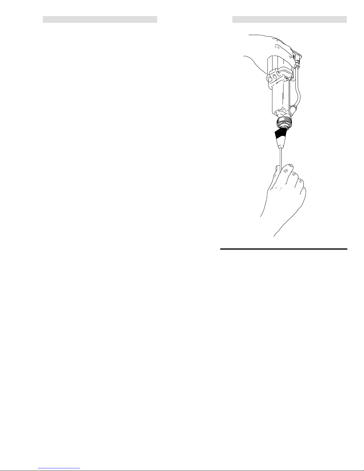
Air Cap/Nozzle/Resistor Stud
Replacement
CAUTION
SURE to
BE
removing
drain
the gun
in
the gun from entering the air passages.
1. Point
fluid
nozzle (14) and resistor stud
the
nozzle wrench (48). This helps drain the gun and
prevent any paint or solvent left in the gun from
entering
If
the resistor stud remains in the gun when the fluid
nozzle is removed, start the nozzle thread onto the
stud
and pull the stud out.
2. Using
resistor
resistor stud contact ring (D) is a conductive con
The
tact
ring, NOT a
sparking, which could cause fire, explosion, or electrostatic shock and result in serious injury, DO NOT
remove
erate the gun without the contact ring in place. DO
NOT replace the resistor stud with anything but a
genuine
hold the front end of the gun up while
the nozzle and resistor stud. This helps
and prevent any paint or solvent left
the front end of the gun up while removing the
(2) assembly with
the air passages. See Fig 15 .
an
8 mm hex key (A), unscrew and remove the
stud (2). See Fig 16 .
WARNING
sealing o-ring. To reduce the risk of
the contact ring from the resistor stud or op
Graco part.
KEY
6,
D Contact
2
Resistor Stud
6, 16,
43
Air Cap Assembly
9
Retaining Ring
12 O-Ring
14
Fluid Nozzle
28 Electrode
31 O-Ring
Nozzle
48
Wrench
Ring
16, 43
12
9
28
14
2
D
48
31
-
Fig 15
0443
14
Torque
10 in-lbs
(1.12 N
to
m)
2
KEY
A
8 mm Hex Key
2
Resistor Stud
14
Fluid Nozzle
T
o install the resistor stud:
3. Lightly lubricate the o-ring (31) with petroleum jelly
and
install it on the resistor stud (2).
4. Using an 8 mm hex key (A), install the resistor stud
(2) in the fluid nozzle (14). T ighten to 10 in-lb
(1.12 N
m).
Make sure the electrode (28) is tightened properly ,
as
shown in Fig 17 , page 20.
5. Install the fluid nozzle (14) and resistor stud (2)
assembly with the nozzle wrench (48). Tighten until
the
fluid nozzle seats in the gun barrel (1/8 to 1/4
past
hand-tight).
turn
6. Install the air cap assembly (6, 16, 43), o-ring (12),
and retaining ring (9). T est gun resistance as
instructed
on page 16.
A
Fig 16
0444
308-08419
Page 20

SERVICE
Electrode Replacement
1. Remove the air cap, nozzle and resistor stud as
described in Air Cap/Nozzle/Resistor Stud
Replacement.
2. Unscrew
with the electrode tool (47) provided. Be careful not
to
damage the contact wire. See Fig 17 .
If
the fluid rod turns, hold the back end of the fluid rod.
3. Apply low-strength
thread
Refer
Hold the back end of the fluid rod to prevent it from
turning
DO
To avoid damaging the plastic threads or contact
wire,
4. Install the fluid nozzle and resistor stud assembly .
Install
as
and remove the fluid needle/electrode (28)
(purple)
Loctite or equivalent
sealant to the electrode and fluid rod threads.
to
SER
VICE NOTES
while installing the new
, page 25.
electrode finger tight.
NOT over tighten the electrode.
CAUTION
be very careful when installing the electrode.
the air cap assembly
. T
est the gun resistance
instructed on page 16.
KEY
28 Electrode
47 Electrode Tool
Apply
low-strength
(purple)
Loctite
or equivalent
47
28
Fig
17
0445
Page 21

SERVICE
Barrel Removal
1. Carefully
(19)
nut
2.
Remove the jam nut (25) and actuator arm (29).
NOTE:
or
installing the jam nut and actuator arm.
3. Using
three
4. Hold the gun body (39) with one hand and pull the
barrel
See
To avoid damaging the power supply
the
necessary, gently move the barrel from side to
side
loosen the fluid fitting nut (21). Pull the tube
out of the fitting. Make sure both ferrules and the
stay with the tube. See Fig 19 .
The fluid nozzle must be in place when
the ball end wrench (46), supplied, loosen
removing
the
socket head cap screws (15). See Fig 20 .
(10) straight
away from the body to remove it.
Fig 18 .
CAUTION
, always pull
gun barrel straight away from the gun body
to free the power supply from the gun body
. If
.
KEY
10 Gun
39
Gun Body
40
Power Supply
Barrel
10
39
40
KEY
7 Jam
10
Gun Barrel
19
Fluid T
21
Fluid Fitting Nut
Fig
19
Nut
ube
25
29
39
Jam Nut
Actuator Arm
Gun Body
10
Fig 18
25 29 7
19
0447
39
21
0446
308-08421
Page 22

Barrel Installation
1. Be
sure the gaskets (23 & 40a) and spring (1
place.
See Fig 20 . Replace if damaged.
SERVICE
1) are in
4.
Install the fluid tube back into the fluid fitting (21).
5. Install
the actuator arm (29) and jam nut (25), with the
jam
nut assembled flush to the end of the rod.
2. Place
the barrel (10) over the power supply (40) and
onto
the gun body (39). Make sure the fluid rod spring
(11)
is seated properly
.
3. Tighten the three socket head cap screws (15)
oppositely
and evenly with the ball end wrench (46).
Tighten the cap screws to 18 in-lbs (2 N m)
MUM
(about a half turn past snug).
DO NOT
tighten.
CAUTION
To
avoid damaging the gun,
DO NOT
over
tighten
the cap screws (15). Tighten the screws to 18 inlbs (2 N m)
snug),
MAXIMUM
using the wrench (46) supplied only
(about a half turn past
.
KEY
10 Gun
11 Spring
15
21
23 Gasket
25
29
39
40
40a Gasket
Barrel
Cap Screws
Fluid T
ube Fitting
Jam Nut
Actuator Arm
Gun body
Power Supply
15
MAXI-
over
There
should be about a 1/16 in. gap between the ac
tuator
arm (29) and the nut on the fluid shaft. When
the gun is triggered, the electrode needle should
draw back 3 to 4 mm. If necessary , adjust the jam
nuts
to obtain these dimensions.
The
jam nut
from
loosening during operation.
6. T
est the gun resistance as instructed on page 16.
must be tightened securely to prevent it
39
40a
40
23
-
Fig 20
10
21
29
25
11
0457
Page 23

SERVICE
Fluid Packing Rod Removal and Repair
NOTE: The fluid packing rod can be replaced as
individual parts or as an assembly . If the assembly is
purchased,
1. Remove
2. Remove
tor stud and electrode as described in Electrode
Replacement.
3. Remove
9
Clean all parts in non-conductive solvent
compatible
or
cause the gun to malfunction.
4. Check
necessary.
Before installing the fluid packing rod assembly (3),
clean the internal surfaces of the barrel with a soft
brush or cloth. Check the inside of the barrel for
marks from high voltage arcing. If the marks are
present,
5.
If the parts are purchased separately ,
them as instructed in steps 6 to 9 and as shown in
Fig 22 .
If installing the complete fluid rod assembly ,
step
it is pre-adjusted at the factory
.
the jam nut (25) and arm (29). See Fig 20 .
the air cap assembly
the fluid packing
, fluid nozzle and resis
rod assembly (3), using the
mm hex nut driver (45). See Fig 21 .
CAUTION
with the fluid being used, such as xylol
mineral spirits. Use of conductive solvents can
all the parts for wear or damage and replace if
replace the barrel.
assemble
go to
10, on page 24.
-
KEY
3 Fluid
45
Packing Rod Assembly
Hex Nut Driver
3
45
Fig 21
6. Place
7. Fill
the packing nut (3c) and o-ring (3g) on the fluid
rod
(3b). The flats on the packing nut must be facing
toward
the back of the fluid rod.
the entire inner cavity of the spacer (3d) with the
dielectric grease included with the gun. Place the
spacer
on the fluid rod (3b), in the direction shown in
Fig
22 . Generously apply the grease to the outside
of
the spacer
.
0448
KEY
E Nut
3 Fluid
3a
3b
3c
3d Spacer
3e
3f
3g O-Ring
11 Spring
Fig
Packing Rod
Assembly
Packing Housing
Fluid Rod
Packing Nut
Rod Packing
Fluid Packing
22
3b
3e
3f
3h
3a
3d
3g
(Item 11 not included with
Fluid Packing Rod Assembly)
11E
3c
3
03224
308-08423
Page 24

SERVICE
Fluid Packing Rod Removal and Repair
(continued)
8. Place the fluid packing (3f), rod packing (3e), and
housing
9. Lightly
is
force
bly
as
10. Lubricate
housing (3a).
(3a) on
tighten the packing nut (3c). The packing nut
properly tightened when there is 2 lbs. (9 N) of drag
when sliding the packing housing (3a) assem
along the shaft. T
needed.
the fluid rod (3b) as shown in Fig 22 .
ighten
or loosen the packing nut
the o-ring (3h) on the outside of the packing
11. Install
12. Make
-
7. Install the electrode, nozzle and resistor stud
8. Install
the fluid packing rod assembly (3) into the gun
barrel.
Using the 9 mm hex nut driver (45), tighten the
assembly
fluid rod.
shown
assembly and the air cap assembly as described in
Electrode
assembled
page 22.
until just snug, then
sure the spring (1
in Fig 22 .
Replacement
the arm
(29) and jam nut (25), with the jam nut
flush to the end of the rod. See Fig 20 ,
1) is installed on the nut (E)
check the drag on the
.
as
Page 25

SERVICE
KEY
F 3-wire
G Potentiometer
10
13
27 Alternator
27a O-Ring
27b Cushion
39
40
40a Gasket
40b Pad
40c Pad
40d Seal
40e Cushion
Connector
Gun Barrel
Retainer Ring
Gun Body
Power Supply
40a
40
40d
10
Fig
23
Power Supply Removal and Replacement
REPAIR
1. Remove
2.
3. Inspect the power supply for any physical damage.
4. Lubricate
5. Install
NOTES:
a. T
o avoid a loss in electrostatic performance,
inspect the gun handle’
s power supply cavity
for dirt or moisture. Clean the cavity with a
clean, dry rag.
b.
Do not expose the seal (40d) or o-ring (27a) to
solvents as solvents will damage them.
the barrel as described in
Barrel Removal
Grasp the power supply (40) with your hand. With a
gentle
side-to-side motion, being careful not to dam
the power supply
age
the
gun handle (39), then pull it straight out.
Check
the electrical
, pull the power supply free
resistance as instructed in
from
Test
Power Supply Resistance. If needed, replace the
power
supply
.
Before installing the power supply, inspect the seal
(40d) for any damage or swelling; replace if necessary. Also, make sure the gaskets/pads (40a–40e)
are
in place.
the
o-ring (27a) and insert the power sup
in the gun handle.
ply
the barrel on the handle as
described in
Barrel
Installation.
40b
G
.
-
-
40e
13
39
40c
F
27a
27b
27
0450
Power Supply Adjustment
The KV HI/LO switch, on the back of the gun manifold,
enables you to switch between full voltage and a lower
voltage
but
output. The lower voltage is factory set at 60 kV
can be adjusted between 45 and 80 kV
.
To adjust the low voltage setting, use a small blade end
screw driver to turn the potentiometer (G), clockwise
increase
fully
the voltage or counterclockwise to decrease it;
clockwise is 80 kV
, fully counterclockwise is 45 kV
to
Turbine Alternator Removal and
Replacement
NOTE: Replace turbine bearings after 2,000 hours of
operation.
1. Remove the power supply from the gun handle as
2. Squeeze the two ends of the retaining ring (13)
3. Use an ohmmeter to test the turbine alternator coil.
4. Connect
See your authorized Graco representative.
described
at left.
together and carefully pull the alternator (27) away
from the power supply (40) until the wire connector
disengages. See Fig 23 .
(F)
Measure
the resistance between the two outer termi
nals of the 3-wire connector (F). Resistance should
be
3 to 5 ohms. If the
replace
the alternator
reading varies from this value,
.
the 3-wire connector to the 3 prongs in the
power
supply
. Push the alternator (27) onto the pow
er supply (40) until the retaining ring (13) engages
with
the alternator
.
,
.
-
-
5. Install the power supply in the gun handle as
described
at left.
308-08425
Page 26

ighten
Nozzle
T
turn past hand tight
SPRAY GUN SERVICE NOTES
Lubricate
1/8 to 1/4
T
ighten
Stud
10 in-lbs (1.15 N
Resistor
into nozzle to
m)
CAUTION: Do not
damage Needle
wire during
trode
assy
. or disassy
Elec
-
.
Apply
ple)
equivalent to threads
Lubricate
low strength
Loctite or
(pur-
CAUTION:
tighten Capscrews
18
in-lbs (2 Nm) MAXIMUM
(about
half turn past snug), us
DO NOT over
wrench provided.
ing
. T
ighten to
Lubricate
-
T
orque
Fitting
(2.8–4.0 N
Install
grooves
to 25–35 in-lbs
m)
into
internal
in fitting
WARNING: DO
NOT remove
contact ring
Lubricate
Fits between
flared tube
and fitting
Stretch o-ring to start
it over fitting threads,
then thread it into
Install
flush to
end
of rod
place
Apply
high strength
(red)
Loctite or
equivalent to threads.
Lubricate
Apply
PTFE paste
to threads
Lubricate
0433
Page 27

Concave side
toward manifold
MANIFOLD SERVICE NOTES
Press
fit
Apply low strength
(purple)
Loctite or
equivalent
T
orque to
25 in-lb
(2.8 N
T
orque to
25 in-lb
(2.8 N
Apply low strength
(purple)
Loctite
or equivalent
m)
m)
Left-hand
threads
Lubricate
Must be
clean
Press fit
T
ighten until
hex bottoms
against manifold
0434
This end 8.5-8.9”
(215-225 mm) from
manifold surface when
properly assembled
Standard o-ring is V
Optional EPR o-ring is
provided with the man
for compatibility with
ifold
ketone
solvents.
iton.
-
Lubricate
orque to
T
25 in-lb
(2.8 N
m)
0434
308-08427
Page 28

SPRAY GUN P
ARTS DRA
WING
REF
NO. 3
Includes items 3a–3h
DETAIL A
3e
3a
3h
0601
43
12
6
3f
3d
16
3g
3c
See
Detail A
28
31
2
3
3b
14
9
27a
27
40e
27b
13
40b
18
40c
25
10
29
REF
15
3
7
36
11
20
REF 19
30
19
21a
21b
21
40
40d
40a
22
42
23
32
8
24
4
1
17
36
41d
39
41f
41a
41h
41j
41c
41b
41i
41g
41e
5
41
0433
Page 29

SPRAY GUN PARTS LIST
Part No. 224–224 Automatic
Electrostatic Air Spray Gun, without shroud
Includes items 1–17, 19–52
Part No. 235–893, Series A
Air Spray Gun, with standard shroud
Includes items 1–52
REF
NO. PART NO. DESCRIPTION QTY
1 186–762 PISTON, valve
2 223–977 STUD, resistor 1
3 224–747 PACKING ROD ASSY
Includes items 3a–3h
3a 185–495
3b 223–981
3c 185–488
3d* 186–069
3e* 178–763
3f* 178–409
3g* 111–504
3h* 111–316
4 186–763 COVER, piston 1
5 111–177 CAP SCREW
6 186–764 RING, air cap 1
7 102–025 NUT
8 100–518 SCREW
9 176–930
10 223–940
11 185–111 SPRING, compression
12{ 110–492 O-RING, PTFE r 1
13 185–114
14 185–158
15 185–096 SCREW
16 177–033
17{ 181–039 PACKING, u-cup, UHMWPE 1
186–770 SHROUD, standard;
188–699 SHROUD, slotted;
19 186–958
20 186–765 ROD, actuator 1
21 187–319 CONNECT
21a* 111–285
21b* 111–286
22 186–818
{ 185–113 GASKET
23
24 181–178 CAP
25 101–324 NUT
27 222–319 ALTERNAT
{ 110–073 SO-RING, Vitonr 1
27a
27b 185–124
28 185–107
29 186–766
30* 102–982 O-RING; PTFE
31* 111–507
32 111–182 SPRING, compression 1
{* 111–450
36
SHOUSING, packing 1
S
ROD, fluid
SNUT
, packing
SSPACER, packing 1
SPACKING, rod 1
SP
ACKING, fluid
S
O-RING, fluoroelastomer
S
O-RING, fluoroelastomer
, button hd; 1/4-20 x 0.5”
, hex; 1/4”-20
, mach, pnh; 6–32 x 3/8”
RING, retaining
BARREL, gun
RING, retainer
NOZZLE, fluid, See Manual 307–803
for available nozzles
AIR CAP; See Manual 307–803 for
available air caps
, alternator
, cap, relieved; M5 x 0.8
included with
Part No. 235–893 only
included with
Part No. 235–894 only
TUBE, flared;
OD tubing; Includes items 21a & 21b
SFERRULE 1
SFERRULE 1
FITTING, fluid; 5/8-20
, retainer
, hex, jam; 1/4”-20
Includes items 27a & 27b
SCUSHION 1
NEEDLE, electrode
ARM, actuator
O-RING; fluoroelastomer
O-RING; fluoroelastomer
PTFE 1
OR, male; 1/8 npt; for 1/4”
, manifold; polyethylene
, spring
OR, turbine
r 1
Part No. 235–894, Series A
Air Spray Gun, with slotted shroud
Includes items 1–52
REF
NO. PART NO. DESCRIPTION QTY
1
1
1
39 224–095 BODY
40 224–093 POWER SUPPLY ASSY
1
1
1
1
1
1
1
1
4
1
1
1
1
3
1
1
1
{ 186–840 SGASKET
40a
40b 185–099
40c 185–145
{ 186–637 SSEAL 1
40d
40e 185–141
41 224–340 CHECK VALVE ASSY
41a 187–264
41b 108–046
41c 101–435
41d 186–980
41e 186–981
41f 186–982
41g 186–983
41h 186–984
41i 186–985
41j 103–337
42* 103–337 O-RING; Viton 2
{ 186–848 GASKET
43
44** 179–791 T
45 110–087
46 107–460 WRENCH, barrel
47 185–123 WRENCH, electrode
48 187–421 WRENCH, nozzle
49** 180–060
50 187–343 COVER, gun
51 110–088
52 105–749 BRUSH 1
* The
replacements for these parts are available in Fluid Seal
Repair
Kit 237–786. Purchase the kit separately
** Additional warning tags and signs available at no charge.
French,
1
1
1
1
1
able. See ACCESSORIES section.
{
The replacements for these parts are available in Air Seal
Repair
When
German,
Kit 224–636. Purchase the kit separately
servicing use only genuine Graco replacement
and Spanish warning signs are also avail
parts. Use of other parts or any modification of the
could alter the grounding continuity of
1
1
1
2
gun
cause
parts to rupture and result in serious injury
explosion,
electrostatic shock or property damage.
, gun
; 85 KV
Includes items 40a–40e
, power supply
SPAD 1
SPAD 1
SCUSHION 1
Includes items 41a-41j
SMUFFLER/FLAME ARRESTOR 1
SBEARING, ball 1
SBEARING, ball 1
SFITTING, check valve; 5/16-18 1
SSCREW, check valve; M4 x 0.7 1
SBODY, check valve; 3/4-16 1
SNUT, check valve; 3/4-16 1
SSEAT, check valve 1
SVALVE, check, body 1
SO-RING; Viton 2
, air cap nut
AG, warning
DRIVER, hex nut; 9 mm
(not shown)
(not shown)
(not shown)
(not shown)
(not shown)
SIGN, warning, English
(not shown)
(not shown)
WRENCH, allen; 8 mm
.
.
WARNING
the gun or
, fire,
1
1
1
1
1
1
1
1
1
1
1
1
1
-
308-08429
Page 30

111
114
MANIFOLD P
110
106
ARTS DRA
WING
122
117d
117c
117h
116
118
117b
117g
104
117e
117f
104
103
107
113
115
MANIFOLD PARTS LIST
124
112
121
101
109
108
0434
Part No. 224–094 Gun Manifold
Includes items 101–124
REF
NO. P
101 111–224 LENSE
103* 106–167
104 110–078
106 186–846 BOLT
107 186–820 MANIFOLD 1
108 183–822
109
110 186–844
111 186–845
112
113 186–779
114 107–107
115 111–157
116 111–237
117 224–143
117a 186–809
117b 186–808
117c 186–810
117d 111–165
117e 224–577
ART NO.
{ 105–668 O-RING; Vitonr 4
{ 105–796 O-RING, Viton 1
DESCRIPTION QTY
O-RING; perfluoroelastomer
FITTING, tube; for 3/8” OD tube
, manifold; M5 x 0.8
SLEEVE, o-ring
FITTING, flow-washer; M16 x 1.5 LH
FITTING, turbine; 1/4-18 npsm LH
FITTING, fiber optic cable; 7/16-20
DISK, regulator
FITTING, tube; for 1/4” OD tube
FITTING, barb
SWITCH, voltage
Includes items 17a-17h
SCYLINDER 1
SPISTON 1
S
FITTING, plug
S
FITTING, male
SMAGNET 1
REF
NO. P
1
117f 111–208 SSPRING, compression 1
2
117g 111–295
2
117h 111–294
3
118 185–819
121 186–847
4
122
123 111–333 O-RING; EPR 1
1
124 224–548 TUBE 1
1
*
1
1
{
1
1
1
1
1
ART NO.
{ 111–180 O-RING; Viton 1
The replacements for these parts are available in Fluid Seal
Repair Kit 237–786. Purchase the kit separately
The replacements for these parts are available in Air Seal
Kit 224–636. Purchase the kit separately
Repair
DESCRIPTION QTY
SSET SCREW
SPACKING, u-cup; UHMWPE 1
FITTING, fluid; 1/4 npsm
SLEEVE, o-ring
, cup point; 4-40
.
.
1
1
1
WARNING
When
servicing use only genuine Graco replacement
parts.
Use of other parts or any modification of the gun
could
alter the grounding continuity of the gun or cause
parts
to rupture and result in serious injury
electrostatic shock, or property damage.
sion,
, fire, explo
-
Page 31

PRO
4600HC CONVERSION KIT
Part
No. 237–301
PRO 4600HC Conversion Kit; To convert the PRO
4600SC
spray gun to the PRO 4600HC spray gun.
The longer 20 in. (508 mm) fluid tube used by the HC
gun provides increased spraying voltage when spray
ing highly conductive fluids. The kit must be ordered
separately
Ref.
No. Part No. Description Qty.
201 237–299 COILED TUBE ASSY. 1
202 112–644 NUT
203 111–285 FERRULE; nylon 1
204 111–286 FERRULE; nylon 1
. It includes items 201 to 204.
; nylon; for 1/4” O.D. tube
201
8.
Slide the nylon nut (202) and ferrules (203 & 204)
onto the coiled tube assembly (201). See Fig. 24 .
9.
Install the coiled tube assembly (201) into the fluid
fitting and tighten the nut (202). See Fig. 27 .
Make sure the entire tube is clear of the actuator
arm (D) to avoid having the tube rub against it dur
-
ing operation.
10.
Install the gun onto the manifold. Refer to page 6.
1
B
A
Fig. 25
04673
202
203
204
Fig.
24
3933A
Installing the PRO 4600HC Conversion Kit
1. Flush
2.
3.
4.
5.
6.
the gun with a compatible solvent.
Relieve system pressure as instructed in the
sure Relief Procedure
on page 18.
Pres-
Remove the gun from the manifold as instructed
on page 18. Remove the gun from the spray area.
Remove the PRO 4600SC gun’
s fluid tube, fittings,
and o-rings (B). See Fig. 25 .
Clean the barrel fluid inlet (A) with compatible sol
vent. Inspect the barrel fluid inlet for damage and
replace if needed.
Slide the coils of the tube assembly (201) over the
front of the gun barrel, until it is past the barrel fluid
inlet (A). See Fig. 26 and 27 .
201
Fig. 26
04674
-
A
C
202D 201
7.
Position the coiled tube assembly so its threaded
inlet fitting (C) is aligned with the barrel fluid inlet
(A), then tighten the fitting into the inlet as shown
in Fig. 27 .
Fig. 27
04672
308-08431
Page 32

ACCESSORIES
Accessories
Use only
GENUINE GRACO PARTS AND ACCESSORIES.
AIR AND FLUID LINE ACCESSORIES
Air Pilot Paint Regulator 224–531
For controlling paint flow through the spray gun.
Connects
to mount assembly 235–094.
Grounded Air Supply Hose
100
psi (7 bar) MAXIMUM WORKING PRESSURE
0.315 in. (8 mm) ID; 1/4 npsm(f) x 1/4 npsm(f) LH;
Color coded black
PAR
T NO.
220–444 6 ft (1.8 m)
218–100 15 ft (5 m)
218–101 25 ft (8 m)
218–102
218–103 50 ft (15 m)
220–119 75 ft (23 m)
220–120
LENGTH
36 ft (1
100 ft (30.5 m)
1 m)
must be purchased separately
Air Filter & Moisture Separator 106–148
250
psi (17.5 bar) MAXIMUM WORKING PRESSURE
For cleaning and drying air in air spray
system. 20 micron element, 5 oz. bowl
capacity
, 3/8 npt(f) inlet and outlet
High Volume Air Regulator 206–199
0331
0–125
psi (0–9 bar) Regulated Pressure
200 psi (14 bar) Steel Pressure Gauge
For regulating air to the gun.
1/2 npt(f) inlet and outlet
Air Shut-off Valve 224–754
150
psi (10 bar) MAXIMUM WORKING PRESSURE
For turning air to gun off or on.
1/4 npsm(m) LH x 1/4 npsm(f) LH
.
Grounded Air Supply Hose
100
psi (7 bar) MAXIMUM WORKING PRESSURE
0.315 in. (8 mm) ID; 1/4 npsm(f) x 1/4 npsm(f) LH;
Color coded gray; More flexible than black hose
PAR
T NO.
223–068 6 ft (1.8 m)
223–069 15 ft (5 m)
223–070 25 ft (8 m)
223–071
223–072 50 ft (15 m)
223–073 75 ft (23 m)
223–074
LENGTH
36 ft (1
100 ft (30.5 m)
1 m)
Grounded Air Supply Hose
100
psi (7 bar) MAXIMUM WORKING PRESSURE
0.315 in. (8 mm) ID; 1/4 npsm(f) x 1/4 npsm(f) LH;
Color coded red; Stainless steel braid ground path
PAR
T NO.
235–068 6 ft (1.8 m)
235–069 15 ft (5 m)
235–070 25 ft (8 m)
235–071
235–072 50 ft (15 m)
235–073 75 ft (23 m)
235–074
LENGTH
36 ft (1
100 ft (30.5 m)
1 m)
Air Adapter Nipple 185–493
For connecting two or more grounded gun air supply
1/4 npt x 1/4 npsm
hoses.
(left hand thread)
Bleed-type Master Air Valve 107–141
300
psi (21 bar) MAXIMUM WORKING PRESSURE
Relieves air trapped in the air line between the paint
pump
air motor and this valve when closed. 3/4 npt
Filter (Air or Paint) 202–271
750
psi (52 bar) MAXIMUM WORKING PRESSURE
With 60 mesh (250 micron) element,
3/8 npt(f) inlet, 3/8 npt(m) outlet
Fluid Drain Valve
500
psi (35 bar) MAXIMUM WORKING PRESSURE
For relieving fluid line pressure
208–630 1/2 npt(m) x 3/8 npt(f); carbon steel and
PTFE;
for non-corrosive fluids
210–071 3/8
npt(m) x 3/8 npt(f); stainless steel
PTFE;
for corrosive fluids
and
Page 33

ACCESSORIES
Accessories
Use only
GENUINE GRACO PARTS AND ACCESSORIES.
must be purchased separately
GUN MOUNTING ACCESSORIES
Gun Mount Assembly 235–094
Bracket for mounting to a 1/2 inch
(12.7
mm) rod,
with
a slot for mount
ing the air pilot fluid regulator
224–531.
01875
Gun Mount Assembly 224–118
For
mounting the PRO4600 gun to the GMF P150
robot.
Mount Extensions 224–255/259
For extending the mount length of Mount Assembly
224–118. Contact your Graco representative for available
lengths.
Nylon Fabric Cover 187–343
Fabric cover to protect the manifold inlet tubing and
fittings
from paint buildup.
.
ES Display Module 224–117
Receives
Gun and displays the gun’s output voltage and current.
Mounts in a standard 19” DIN Rack. Refer to manual
308–265.
fiber optic transmission from the PRO 4600SC
0309
24 Volt Power Supply 235–301
Provides
24 volt power for up to 23 ES Display Modules.
187–343
0437
GUN CONTROL AND MONITORING
ACCESSORIES
For mor
accessories
e i
nformatio
n a
bou
t gun c
ontrol
contact your Graco representative.
s and m
onitoring
Pneumatic Trigger Module 235–768
Provides pilot air valve control for atomizing air , fan air
and fluid trigger air gun functions. Refer to manual
308–264.
01768
01339
308-08433
Page 34

ACCESSORIES
Accessories
Use only
GENUINE GRACO PARTS AND ACCESSORIES.
must be purchased separately
CABLE ACCESSORIES
Fiber Optic Cables
Fiber
Optic Cable Assembly
For connection between gun manifold and display
module or between bulkhead connector and display
module.
PART
NO.
LENGTH
224–680 6 ft (1.8 m)
224–681 15 ft (5 m)
224–682 25 ft (8 m)
224–683
224–684 50 ft (15 m)
224–685 75 ft (23 m)
224–686
36 ft (1
1 m)
100 ft (30.5 m)
.
Bulkhead Connector 224–261
For
connection between two fiber optic cables.
MISCELLANEOUS ACCESSORIES
Grounding Clamp and Wire 222–011
12
ga, 25 ft (7.6 m) wire
0185A
Fiber Optic Cable Extender
For
connection between
gun manifold and bulkhead con
nector.
PART
NO.
LENGTH
224–670 6 ft (1.8 m)
224–671 15 ft (5 m)
224–672 25 ft (8 m)
224–673
36 ft (1
1 m)
224–674 50 ft (15 m)
224–675 75 ft (23 m)
224–676
100 ft (30.5 m)
0330
0184
Megohmmeter 218–979
500 Volt output; 0.01–2000 megohms.
-
Not for use in Hazardous areas.
0189
Page 35

Safety Warning Signs
PTFEPTFEPTFE
Available
Must be ordered separately
at no charge from Graco.
PAR
T NO.
180–060 W
180–061 W
180–062 W
180–063 W
DESCRIPTION
arning Sign (English)
arning Sign (French)
arning Sign (German)
arning Sign (Spanish)
.
Paint Resistance Meter 722–886
Used
with
722–860 Paint Probe to measure resistance of
paint. Not for use in Hazardous areas.
Paint Probe 722–860
Used
with 722–886 Paint Resistance Meter to
measure resistance of paint.
Not for use in
Hazardous areas.
Gun High Voltage Probe & Meter 217–452
For
direct measurement of gun output voltage.
SYSTEMS
Gun, Manifold, and Mount System 235–303
Includes:
PART
NO.
DESCRIPTION
224–224
224–094
235–094
PRO4600 Gun
Gun Manifold
Standard Gun Mount
TECHNICAL DA
TA
MANUAL CHANGE SUMMAR
The
following parts have been changed in this revision:
Assembly
Changed
224–635,
224–224,
235–893 &
235–894
Spray Gun
Miscellaneous Changes:
Changed the Fluid Seal Repair Kit from part no.
1.
224–635 to part no. 237–786.
2.
Added the PRO 4600HC Conversion Kit, part no.
237–301 to the manual.
Part
Status
Old
New
Added
Added
Ref
Part No. Name
No.
3
223–980
3
224–747
51
110–088
52
105–749
Packing Rod
Packing Rod
Wrench
Brush
Y
Weight
Maximum Working Pressure
Air
Fluid
Voltage
Paint
Turbine
Wetted Parts Stainless Steel, Nylon, Acetal,.
(gun & manifold)
.
. . . . . . . . . . . . .
Pressure Operating Range
Pressure Operating Range
Output
Resistivity Range
Air Inlet
.
. . . . . . . . . . . . . . . . . . . . . . . . . .
.
. . . .
.
. . . . . . . . . . . . . . . . .
. . . . .
43 oz (1207 g)
.
. . . . . . . . .
.
. .
.
100 psi (7 bar)
0–100 psi (0–7 bar)
0–100 psi (0–7 bar)
3 megohm cm to infinity
1/4 npsm(m) L.H.
, Kalrez , Ultra High
Molecular W eight Polyethylene,
Ceramic, Chemraz , Fluoropolymer
Viton and Kalrez are registered trademarks of the
Co.
DuPont
Loctite
is a registered trademark of the Loctite Corporation.
Chemraz
is a registered trademark of the Green, T
weed, & Co.
0–85 kV
Page 36

THE
GRACO W
ARRANTY AND DISCLAIMERS
WARRANTY
Graco
warrants all equipment manufactured by it and bearing its name to be free from defects in material and workman
ship on the date of sale by an authorized Graco distributor to the original purchaser
for
breach of this warranty
repair
or replace any part of the equipment proven defective. However
internal
thousand
maintained
This
lation,
substitution
power supply
hours of operation from time of sale. This warranty applies only when the
in accordance with Graco’
warranty does not cover
misapplication, abrasion, corrosion, inadequate or improper maintenance, negligence, accident, tampering, or
of non–Graco component parts. Nor shall Graco be liable for malfunction, damage or wear caused by the
incompatibility with Graco equipment of
improper
als
This
design, manufacture, installation, operation or
not supplied by Graco.
warranty is conditioned upon the prepaid return of the equipment claimed to be defective to an authorized Graco
, Graco will, for a period of twelve months or two thousand
, any deficiency in the barrel, handle, trigger
, and alternator (excluding turbine bearings) will be repaired or replaced for thirty-six months or six
s written recommendations.
, and Graco shall not be liable for
, any malfunction, damage or wear caused by faulty
structures, accessories, equipment or materials not supplied by Graco, or the
maintenance of structures, accessories, equipment or materi
for
use. As purchaser’s sole remedy
hours of operation from time of sale,
, hook,
equipment is installed, operated and
instal
distributor for verification of the claim. If the claimed defect is verified, Graco will repair or replace free of charge any
defective parts. The equipment will be returned to the original purchaser transportation prepaid. If inspection of the
equipment
charges
does not disclose any defect in material or workmanship, repairs will be made at a reasonable charge, which
may include the costs of parts, labor and transportation.
-
-
-
DISCLAIMERS AND LIMIT
The
terms of this warranty constitute purchaser’s sole and exclusive remedy and are in lieu of any other warranties (express or im
plied),
including warranty of merchantability or warranty of fitness for a
ties,
including product liabilities, based on negligence or strict liability
ages
or loss is expressly excluded and denied. in no case shall Graco’
for
breach of warranty must be brought within two (2) years of the date of sale.
EQUIPMENT
Graco
makes no warranty
spect
to accessories, equipment, materials, or components sold but not manufactured by Graco.
factured
Graco
will provide purchaser with reasonable assistance in making any claim for breach of these warranties.
NOT COVERED BY GRACO W
by Graco
(such as electric motor
ATIONS
, and disclaims all implied
, switches, hose, etc.) are subject to the warranty
particular purpose,
. Every form of liability for direct, special or consequential dam
s liability exceed the amount of the purchase price. Any action
and of any non–contractual liabili
ARRANTY
warranties of merchantability and fitness for
These
a particular purpose,
items sold, but not manu
, if any
, of their manufacturer
GRACO PHONE NUMBERS
TO
PLACE AN ORDER
or call Graco:
1–800–367–4023 T
, contact your Graco distributor
oll Free
,
FOR TECHNICAL ASSISTANCE
mation
or answers about the application of Graco equip
ment,
call:
1–800–543–0339 T
, service repair infor-
oll Free
with re
-
-
-
-
.
-
Sales
Offices:
Foreign Offices:
GRACO
Atlanta, Chicago, Dallas, Detroit, Los Angeles, Mt. Arlington (N.J.)
Canada; England; Switzerland; France; Germany; Hong Kong; Japan; Korea
INC.P.O. BOX 1441
PRINTED
IN U.S.A.
36 308-084
308–084
MINNEAPOLIS, MN
June 1991 Revised January 1995
55440–1441
 Loading...