

Page 1
Instructions – Parts List
PRECISIONMIX II
3K System
309107E
For Proportional Mixing of Two and Three Component Coatings
Patent No. 5,368,059
Read warnings and instructions.
See page 2 for the Table of Contents.
Conforms to ANSI/UL
standard 2279
Class 1 Zone 0
AExia II A T4
110474
Certified to CAN/CSA
22.2 No. E79–11
0359
II 2 G
EEXia II A T3
ITS03ATEX21382
GRACO INC.ąP.O. BOX 1441ąMINNEAPOLIS, MNą55440-1441
Copyright 2001, Graco Inc. is registered to I.S. EN ISO 9001
Page 2

Table of Contents
Warnings 1–1. . . . . . . . . . . . . . . . . . . . . . . . . . . . . . . . . . .
Overview 2–1. . . . . . . . . . . . . . . . . . . . . . . . . . . . . . . . . . .
Using this Manual 2–3. . . . . . . . . . . . . . . . . . . . . . . . .
Related Publications 2–4. . . . . . . . . . . . . . . . . . . . . .
How the PrecisionMix II 3K Works 2–6. . . . . . . . . .
Functional Diagrams 2–7. . . . . . . . . . . . . . . . . . .
Changing the Mixing Order 2–10. . . . . . . . . . . . . . . .
Flow Control Overview 2–12. . . . . . . . . . . . . . . . . . .
Flow Control Features 2–12. . . . . . . . . . . . . . . .
System Requirements 2–12. . . . . . . . . . . . . . . .
General Operation Sequence 2–12. . . . . . . . . .
One Gun Flow Control Using a Flow Meter
in the Mixed Material Line 2–13. . . . . . . . . .
Flow Control Components 2–14. . . . . . . . . . . . .
Flow Control Parameters 2–15. . . . . . . . . . . . . .
Using Recipes/Color Change 2–16. . . . . . . . . . . . . .
No Color Change 2–16. . . . . . . . . . . . . . . . . . . . .
Integrated Color Change 2–16. . . . . . . . . . . . . .
Integrated Color Change with Queue 2–17. . . .
Color Change Sequences 2–18. . . . . . . . . . . . .
Changing from One Color Change
Sequence to Another 2–19. . . . . . . . . . . . . .
Actual Valve Times 2–20. . . . . . . . . . . . . . . . . . .
Installation 3–1. . . . . . . . . . . . . . . . . . . . . . . . . . . . . . . . .
Typical Installation 3–3. . . . . . . . . . . . . . . . . . . . . . . .
Non-intrinsically Safe 3–4. . . . . . . . . . . . . . . . . .
Intrinsically Safe 3–5. . . . . . . . . . . . . . . . . . . . . .
Fluid Supply Requirements 3–6. . . . . . . . . . . . . . . . .
Mounting Components 3–7. . . . . . . . . . . . . . . . . . . .
For Wall Mounting 3–7. . . . . . . . . . . . . . . . . . . . .
Stand Mounting Kit 241501 3–9. . . . . . . . . . . . .
System Installation 3–10. . . . . . . . . . . . . . . . . . . . . . .
Install the Controller and User Interface 3–10.
Power Requirements 3–11. . . . . . . . . . . . . . . . .
Install the Fluid Panel with Fluid Meters 3–12.
Install the Air Control Kit 3–13. . . . . . . . . . . . . .
Install the Operator Station 3–13. . . . . . . . . . . .
Install the Color/Catalyst/Reducer
Change Valves and Solenoids 3–14. . . . . .
Install the Gun Flush Box and
Solenoid Box 3–16. . . . . . . . . . . . . . . . . . . . .
Install the Optional Flow Control 3–20. . . . . . . .
Fluid Connections 3–20. . . . . . . . . . . . . . . . . . . .
Pressure Test and Solvent Flush
the System 3–20. . . . . . . . . . . . . . . . . . . . . .
Digital Outputs 3–21. . . . . . . . . . . . . . . . . . . . . . .
Component Electrical Connections 3–22. . . . . . . . .
Controller Terminal Block 3–29. . . . . . . . . . . . . . . . .
Ground the System 3–30. . . . . . . . . . . . . . . . . . . . . .
Check the Resistance 3–31. . . . . . . . . . . . . . . . . . . .
Power-up Checklist 3–32. . . . . . . . . . . . . . . . . . . . . .
Checking Flow Control I/P Transducers 3–34.
Testing Flow Control External 4–20 mA Input
Signal 3–35. . . . . . . . . . . . . . . . . . . . . . . . . . .
Pressure Test and Solvent Flush Procedure 3–36.
Test Color Valve Operation 3–36. . . . . . . . . . . .
Pressure Test Component A 3–36. . . . . . . . . . .
Pressure Test Component B and C 3–36. . . . .
Pressure Test the Solvent Lines 3–36. . . . . . . .
Operation 4–1. . . . . . . . . . . . . . . . . . . . . . . . . . . . . . . . . . .
Pressure Relief Procedure 4–3. . . . . . . . . . . . . . . . .
Operator Controls and Indicators 4–4. . . . . . . . . . . .
Operator Station 4–4. . . . . . . . . . . . . . . . . . . . . .
User Interface 4–6. . . . . . . . . . . . . . . . . . . . . . . .
Operating Checklist 4–7. . . . . . . . . . . . . . . . . . . . . . .
Mode Switch 4–7. . . . . . . . . . . . . . . . . . . . . . . . . . . . .
Purging the Ratio Check Valves 4–8. . . . . . . . . . . . .
Purging the PrecisionMix II 3K System 4–10. . . . . .
Starting Production 4–12. . . . . . . . . . . . . . . . . . . . . . .
Stopping Production 4–14. . . . . . . . . . . . . . . . . . . . . .
Flow Control Operation 4–15. . . . . . . . . . . . . . . . . . .
Flow Control Tips 4–15. . . . . . . . . . . . . . . . . . . . . . . .
Integrated Color Change 4–16. . . . . . . . . . . . . . . . . .
Multiple Gun Flush Box Operation 4–16. . . . . . . . . .
Printer Reports 4–18. . . . . . . . . . . . . . . . . . . . . . . . . .
Run Mode Report 4–18. . . . . . . . . . . . . . . . . . . .
Recipe Report 4–19. . . . . . . . . . . . . . . . . . . . . . .
System Setup (Configuration) Report 4–20. . .
Job Totals Report 4–22. . . . . . . . . . . . . . . . . . . .
Batch Totals Report 4–22. . . . . . . . . . . . . . . . . .
Grand Totals Report 4–23. . . . . . . . . . . . . . . . . .
Alarm Report 4–23. . . . . . . . . . . . . . . . . . . . . . . .
Screen Map 5–1. . . . . . . . . . . . . . . . . . . . . . . . . . . . . . . . .
Run Monitor 6–1. . . . . . . . . . . . . . . . . . . . . . . . . . . . . . . .
Home Screen 6–3. . . . . . . . . . . . . . . . . . . . . . . . . . . .
Target/Actual 6–3. . . . . . . . . . . . . . . . . . . . . . . . . . . . .
Flow Rate 6–4. . . . . . . . . . . . . . . . . . . . . . . . . . . . . . .
Potlife Timer 6–4. . . . . . . . . . . . . . . . . . . . . . . . . . . . .
Flow Rate Setpoint 6–5. . . . . . . . . . . . . . . . . . . . . . . .
Enter New Setpoint 6–5. . . . . . . . . . . . . . . . . . . . . . .
Recipe Select 6–5. . . . . . . . . . . . . . . . . . . . . . . . . . . .
Alarm History 6–6. . . . . . . . . . . . . . . . . . . . . . . . . . . .
Integrated Color Change with Queue 6–7. . . . . . . .
Modify Queue Screen 6–8. . . . . . . . . . . . . . . . . . . . .
Totalizers 7–1. . . . . . . . . . . . . . . . . . . . . . . . . . . . . . . . . . .
Home Screen 7–3. . . . . . . . . . . . . . . . . . . . . . . . . . . .
Select Recipe and Totalizer Screen 7–3. . . . . . . . . .
Job Totals 7–4. . . . . . . . . . . . . . . . . . . . . . . . . . . . . . .
Batch Totals 7–4. . . . . . . . . . . . . . . . . . . . . . . . . . . . . .
Grand Totals 7–5. . . . . . . . . . . . . . . . . . . . . . . . . . . . .
2
Page 3

Table of Contents
System Configuration 8–1. . . . . . . . . . . . . . . . . . . . . . .
Home Screen 8–3. . . . . . . . . . . . . . . . . . . . . . . . . . .
Password Screen 8–3. . . . . . . . . . . . . . . . . . . . . . . . .
Menu Screen 8–4. . . . . . . . . . . . . . . . . . . . . . . . . . . . .
Language 8–5. . . . . . . . . . . . . . . . . . . . . . . . . . . . . . . .
Station Number 8–5. . . . . . . . . . . . . . . . . . . . . . . . . . .
Display Units of Measurement 8–6. . . . . . . . . . . . . .
Recipes 8–6. . . . . . . . . . . . . . . . . . . . . . . . . . . . . . . . .
Potlife Timer 8–7. . . . . . . . . . . . . . . . . . . . . . . . . . . . .
Flow Rate Limits 8–7. . . . . . . . . . . . . . . . . . . . . . . . . .
Solvent Meter 8–8. . . . . . . . . . . . . . . . . . . . . . . . . . . .
Purge Sequence: Valves 8–8. . . . . . . . . . . . . . . . . . .
Purge Sequence: Purge Alarms 8–9. . . . . . . . . . . .
Mixed Load Volumes 8–10. . . . . . . . . . . . . . . . . . . . .
Guns Setup 8–10. . . . . . . . . . . . . . . . . . . . . . . . . . . . .
Mix/Purge 8–11. . . . . . . . . . . . . . . . . . . . . . . . . . . . . .
Flow Control 8–11. . . . . . . . . . . . . . . . . . . . . . . . . . . .
Integrator Volume 8–12. . . . . . . . . . . . . . . . . . . . . . . .
Integrated Color Change 8–12. . . . . . . . . . . . . . . . . .
Password Selection 8–12. . . . . . . . . . . . . . . . . . . . . .
Time and Date Set 8–13. . . . . . . . . . . . . . . . . . . . . . .
Display Setup 8–14. . . . . . . . . . . . . . . . . . . . . . . . . . .
Print Setup 8–14. . . . . . . . . . . . . . . . . . . . . . . . . . . . . .
Air Flow Switch 8–15. . . . . . . . . . . . . . . . . . . . . . . . . .
Flow Control Setup 8–16. . . . . . . . . . . . . . . . . . . . . . .
Home Screen 8–16. . . . . . . . . . . . . . . . . . . . . . .
Password Screen 8–16. . . . . . . . . . . . . . . . . . . .
Menu Screen 8–16. . . . . . . . . . . . . . . . . . . . . . . .
Flow Control Options 8–17. . . . . . . . . . . . . . . . .
Flow Control Menu 8–17. . . . . . . . . . . . . . . . . . .
Source of Flow Control Data 8–18. . . . . . . . . . .
Flow Control Scaling 8–18. . . . . . . . . . . . . . . . . .
Flow Control Force Output 8–19. . . . . . . . . . . .
Flow Control Delay Time 8–19. . . . . . . . . . . . . .
Flow Control Meter Location 8–20. . . . . . . . . . .
Integrated Color Change Setup 8–21. . . . . . . . . . . .
Home Screen 8–21. . . . . . . . . . . . . . . . . . . . . . .
Password Screen 8–21. . . . . . . . . . . . . . . . . . . .
Menu Screen 8–21. . . . . . . . . . . . . . . . . . . . . . . .
Color Change Mode Screen 8–22. . . . . . . . . . .
Color Change Sequence 8–22. . . . . . . . . . . . . .
Color Change Graph Screen 8–23. . . . . . . . . . .
Purge and Mix Timer Values 8–23. . . . . . . . . . .
A Component Dump Timer Value 8–24. . . . . . .
A Component Solvent Timer Value 8–24. . . . .
B Component Dump Timer Value 8–25. . . . . . .
B Component Solvent Timer Value 8–25. . . . .
C Component Dump Timer Valve 8–26. . . . . . .
C Component Solvent Timer Valve 8–26. . . . .
Gun 1 Trigger Start/Duration Times 8–27. . . . .
Gun 2 Trigger Start/Duration Times 8–27. . . . .
Special 1, 2, 5, and 6
Trigger Start/Duration Times 8–28. . . . . . .
PrecisionMix II 3K Robotic Interface 8–29. . . . . . . .
Pressure Test and Solvent Flush
the System 8–29. . . . . . . . . . . . . . . . . . . . . .
PrecisionMix II 3K Robotic Applications 8–29.
Integrated Color Change 8–30. . . . . . . . . . . . . .
Non-integrated Color Change 8–31. . . . . . . . . .
Digital Inputs 8–32. . . . . . . . . . . . . . . . . . . . . . . .
Recipe Setup 9–1. . . . . . . . . . . . . . . . . . . . . . . . . . . . . . .
Home Screen 9–3. . . . . . . . . . . . . . . . . . . . . . . . . . .
Password Screen 9–3. . . . . . . . . . . . . . . . . . . . . . . . .
Recipe Selection 9–4. . . . . . . . . . . . . . . . . . . . . . . . . .
Setup Menu with Integrated Color Change On
and Flow Control On 9–5. . . . . . . . . . . . . . . . . . .
Setup Menu with Integrated Color Change
and Flow Control Off 9–5. . . . . . . . . . . . . . . . . . .
Mix Ratio and Tolerance 9–6. . . . . . . . . . . . . . . . . . .
Color Change Sequence 9–7. . . . . . . . . . . . . . . . . . .
Purge Sequence 9–8. . . . . . . . . . . . . . . . . . . . . . . . . .
System Alarms with Flow Control On and
Hand Gun Selected 9–9. . . . . . . . . . . . . . . . . . . .
System Alarms with Flow Control On and
Automatic Gun Selected 9–10. . . . . . . . . . . . . .
System Alarms with Flow Control Off 9–10. . . . . . .
Meter Calibration Tests 9–11. . . . . . . . . . . . . . . . . . .
Component A Flow Meter Calibration 9–12. . . . . . .
Component B Flow Meter Calibration 9–13. . . . . . .
Component C Flow Meter Calibration 9–13. . . . . . .
Solvent Flow Meter Calibration 9–14. . . . . . . . . . . .
Mixed Material Calibration Screen 9–14. . . . . . . . . .
Gun 1 Meter Calibration 9–15. . . . . . . . . . . . . . . . . .
Setup Flow Control 9–16. . . . . . . . . . . . . . . . . . . . . . .
Gain Factor Graphs 9–17. . . . . . . . . . . . . . . . . . . . . .
Flow Meter Calibration Procedure 9–18. . . . . . . . . .
Selection 1, 2, 3, or 4: Calibrating the
Meters Individually 9–18. . . . . . . . . . . . . . . .
Selection 6: Calibrating the Gun 1 Meter 9–20
Selection 5: Mixed Material Calibration 9–21. .
3
Page 4

Table of Contents
Troubleshooting 10–1. . . . . . . . . . . . . . . . . . . . . . . . . . .
Revision Number 10–2. . . . . . . . . . . . . . . . . . . . . . . .
Troubleshooting Reference 10–3. . . . . . . . . . . . . . . .
Alarm Troubleshooting 10–7. . . . . . . . . . . . . . . . . . . .
To Clear the Alarm and
Restart the System 10–7. . . . . . . . . . . . . . .
Ratio Low or Ratio High 10–8. . . . . . . . . . . . . . .
Dose Time A, B, or C 10–9. . . . . . . . . . . . . . . . .
Overdose A, B, or C 10–9. . . . . . . . . . . . . . . . . .
Flow Rate Alarms for a System without
Flow Control 10–10. . . . . . . . . . . . . . . . . . .
Flow Too Low 10–10. . . . . . . . . . . . . . . . . .
Flow Too High 10–10. . . . . . . . . . . . . . . . . .
Flow Rate Alarms for a System with
Flow Control 10–10. . . . . . . . . . . . . . . . . . .
Gun #1 High/Low Flow 10–10. . . . . . . . . .
Gun # 2 High/Low Flow 10–10. . . . . . . . . .
Pot Life Exceeded 10–10. . . . . . . . . . . . . . . . . .
Purge/Load Interlock Not Ready 10–11. . . . . . .
Invalid Recipe 10–11. . . . . . . . . . . . . . . . . . . . . .
I/O Change 10–11. . . . . . . . . . . . . . . . . . . . . . . . .
Purge Not Completed 10–11. . . . . . . . . . . . . . . .
Purge Time Out 10–11. . . . . . . . . . . . . . . . . . . . .
Display Battery Low 10–12. . . . . . . . . . . . . . . .
Control Battery Low 10–12. . . . . . . . . . . . . . . .
Memory Failure 10–12. . . . . . . . . . . . . . . . . . . .
Communications Error 10–12. . . . . . . . . . . . . .
Invalid Guns From Input/Output Alarm 10–12
Air Flow Switch Alarm 10–12. . . . . . . . . . . . . .
Defaults Loaded 10–12. . . . . . . . . . . . . . . . . . .
Software Revision Alarm 10–12. . . . . . . . . . . .
Configuration Module Alarm 10–12. . . . . . . . .
External Alarms 10–12. . . . . . . . . . . . . . . . . . . .
Warnings 10–13. . . . . . . . . . . . . . . . . . . . . . . . . .
Job Total Rollover 10–13. . . . . . . . . . . . . . . . . .
Batch Total Rollover 10–13. . . . . . . . . . . . . . . .
Grand Total Rollover 10–13. . . . . . . . . . . . . . . .
Calibrate A Meter 10–13. . . . . . . . . . . . . . . . . .
Calibrate B Meter 10–13. . . . . . . . . . . . . . . . . .
Calibrate C Meter 10–13. . . . . . . . . . . . . . . . . .
Solenoid Box Troubleshooting 10–14. . . . . . . . . . .
Gun Flush Box Troubleshooting 10–16. . . . . . . . . .
Operator Station
with Color Change Troubleshooting 10–17. . .
Service 11–1. . . . . . . . . . . . . . . . . . . . . . . . . . . . . . . . . . . .
Replacing the User Interface Battery 11–3. . . . . . .
Replacing the Controller Battery 11–4. . . . . . . . . . .
Replacing Isolation Barrier Fuses 11–5. . . . . . . . . .
Replacing the User Interface 11–5. . . . . . . . . . . . . .
Replacing the Power Supply 11–6. . . . . . . . . . . . . . .
Changing the Power Supply Voltage 11–6. . . . . . . .
Replacing Power Supply Fuses 11–6. . . . . . . . . . . .
Servicing the Operator Station 11–7. . . . . . . . . . . . .
Replacing Control Modules 11–8. . . . . . . . . . . . . . . .
Replacing Control Submodules 11–9. . . . . . . . . . . .
4
Parts 12–1. . . . . . . . . . . . . . . . . . . . . . . . . . . . . . . . . . . . . .
Controller with User Interface 12–3. . . . . . . . . . . . . .
Part No. 243540 12–3. . . . . . . . . . . . . . . . . . . . .
Part No. 243541 12–3. . . . . . . . . . . . . . . . . . . . .
Controller 12–4. . . . . . . . . . . . . . . . . . . . . . . . . . . . . . .
Part No. 240834 12–4. . . . . . . . . . . . . . . . . . . . .
Flow Control 12–6. . . . . . . . . . . . . . . . . . . . . . . . . . . .
One Gun 12–6. . . . . . . . . . . . . . . . . . . . . . . . . . . .
One Gun with Flow Meter in
Mixed Material Line 12–6. . . . . . . . . . . . . . .
Communication Ports 12–8. . . . . . . . . . . . . . . . . . . .
Part No. 241379 12–8. . . . . . . . . . . . . . . . . . . . .
Part No. 241378 12–8. . . . . . . . . . . . . . . . . . . . .
Software Utilities Kit 12–8. . . . . . . . . . . . . . . . . . . . . .
Part No. 243546 12–8. . . . . . . . . . . . . . . . . . . . .
Fluid Panel 12–9. . . . . . . . . . . . . . . . . . . . . . . . . . . . . .
Non-Intrinsically Safe 12–9. . . . . . . . . . . . . . . . .
Intrinsically Safe 12–9. . . . . . . . . . . . . . . . . . . . .
Fluid Panel Module 12–10. . . . . . . . . . . . . . . . . . . .
Part No. 243493 12–10. . . . . . . . . . . . . . . . . . .
Solenoid Module 12–12. . . . . . . . . . . . . . . . . . . . . . .
Part No. 552184 12–12. . . . . . . . . . . . . . . . . . .
Part No. 552186 12–12. . . . . . . . . . . . . . . . . . .
Fluid Meters 12–13. . . . . . . . . . . . . . . . . . . . . . . . . .
Part No. 243512 12–13. . . . . . . . . . . . . . . . . . .
Part No. 243513 12–13. . . . . . . . . . . . . . . . . . .
Part No. 243515 12–14. . . . . . . . . . . . . . . . . . .
Air Supply Station 12–16. . . . . . . . . . . . . . . . . . . . . .
Part No. 570122 12–16. . . . . . . . . . . . . . . . . . .
Operator Station 12–17. . . . . . . . . . . . . . . . . . . . . . .
Part No. 240835 12–17. . . . . . . . . . . . . . . . . . .
Part No. 240877 12–18. . . . . . . . . . . . . . . . . . .
Low Pressure Color Change Module 12–19. . . . .
Part No. 241386 12–19. . . . . . . . . . . . . . . . . . .
Part No. 242025 12–19. . . . . . . . . . . . . . . . . . .
Part No. 241387 12–20. . . . . . . . . . . . . . . . . . .
Part No. 242026 12–20. . . . . . . . . . . . . . . . . . .
High Pressure Color Change Module 12–22. . . . .
Part No. 241499 12–22. . . . . . . . . . . . . . . . . . .
Part No. 241500 12–23. . . . . . . . . . . . . . . . . . .
Part No. 907347 12–25. . . . . . . . . . . . . . . . . . .
Color Change Valve Assemblies 12–26. . . . . . . . .
Low Pressure Color Change Valves 12–26. . .
High Pressure Color Change Valves 12–26. .
Valve Bracket Changing Procedure 12–27. . .
Page 5

Table of Contents
Gun Flush Box 12–28. . . . . . . . . . . . . . . . . . . . . . . .
Part No. 241389 12–28. . . . . . . . . . . . . . . . . . .
Part No. 241394 12–28. . . . . . . . . . . . . . . . . . .
Gun Flush Solenoid Box 12–29. . . . . . . . . . . . . . . .
Part No. 115125 12–29. . . . . . . . . . . . . . . . . . . .
Gun Holders for Gun Flush Box 12–30. . . . . . . . . .
Cable Chart 12–31. . . . . . . . . . . . . . . . . . . . . . . . . . .
Remote User Interface 12–32. . . . . . . . . . . . . . . . .
Part No. 240874 12–32. . . . . . . . . . . . . . . . . . .
Stand Mount 12–33. . . . . . . . . . . . . . . . . . . . . . . . . .
Part No. 241501 12–33. . . . . . . . . . . . . . . . . . .
Audio/Visual Alarm 12–33. . . . . . . . . . . . . . . . . . . . .
Part No. 241380 12–33. . . . . . . . . . . . . . . . . . .
Accessories 12–34. . . . . . . . . . . . . . . . . . . . . . . . . . .
Part No. 241647 Catalyst Change Kit 12–34.
Part No. 195048 Paint Shield 12–34. . . . . . . .
Part No. 195049 Paint Shield 12–34. . . . . . . .
Part No. 241263 Printer Kit 12–34. . . . . . . . . .
Printer Power Supply 12–34. . . . . . . . . . . . . . .
Part No. 514037 Printer Paper 12–34. . . . . . .
Manual Dump Valve Kits 12–35. . . . . . . . . . . .
2K Fluid Outlet Valves 12–35. . . . . . . . . . . . . .
Part No. 513052 Air Flow Switch 12–35. . . . .
Part No. 241962 Hydro-Softfeel
Material Application Kit 12–35. . . . . . . . . .
Cable Network PC AMR 12–35. . . . . . . . . . . . .
Catalyst Supply Modules 12–35. . . . . . . . . . . .
Utilities Software 13–1. . . . . . . . . . . . . . . . . . . . . . . . . . .
Utilities Overview 13–3. . . . . . . . . . . . . . . . . . . . . . . .
Connection Error 13–3. . . . . . . . . . . . . . . . . . . . . . . .
Mode Switch 13–3. . . . . . . . . . . . . . . . . . . . . . . . . . . .
Backup PrecisionMix II 13–4. . . . . . . . . . . . . . . . . . .
Restore PrecisionMix II 13–7. . . . . . . . . . . . . . . . . . .
Update the Operating System 13–9. . . . . . . . . . . . .
Update PrecisionMix II Program 13–11. . . . . . . . . .
Connecting Utilities 13–12. . . . . . . . . . . . . . . . . . . .
Update User Interface Program 13–13. . . . . . . . . .
Reset PrecisionMix II Password 13–15. . . . . . . . .
Set PrecisionMix II Date and Time 13–16. . . . . . .
Open Graco Web Site 13–17. . . . . . . . . . . . . . . . . .
Edit Language 13–17. . . . . . . . . . . . . . . . . . . . . . . . .
Technical Data 14–1. . . . . . . . . . . . . . . . . . . . . . . . . . . . .
Graco Standard Warranty 14–6. . . . . . . . . . . . . . . . . . .
Graco Phone Number 14–6. . . . . . . . . . . . . . . . . . . . . .
5
Page 6

6
Page 7

1
Warnings
1–1Warnings
Page 8

1–2 Warnings
Page 9
WARNING
FIRE, EXPLOSION, AND ELECTRIC SHOCK HAZARD
Improper grounding, poor air ventilation, open flames, or sparks can cause a hazardous condition and
result in fire or explosion and serious injury.
The PrecisionMix Controller must only be installed and serviced by a qualified electrician.
The PrecisionMix Controller is for use only in non-hazardous locations. The maximum applied relay
voltage shall not exceed +24 volts. Do not operate the controller in hazardous locations, as defined
in Article 500 of the National Electrical Code (USA).
Ground the equipment and the object being sprayed. See Ground the System on page 3–30.
Do not install non-intrinsically safe equipment in a hazardous area.
Provide fresh air ventilation to avoid the buildup of flammable vapors from solvent or the fluid being
sprayed.
Extinguish all the open flames or pilot lights in the spray area.
Keep the spray area free of debris, including solvent, rags, and gasoline.
Do not turn on or off any light switch in the spray area while operating or if fumes are present.
Do not smoke in the spray area.
Do not operate a gasoline engine in the spray area.
If there is any static sparking while using the equipment, stop spraying immediately. Identify and
correct the problem.
Keep liquids away from the electrical components.
Disconnect electrical power at the main switch before servicing the equipment.
The battery inside the PrecisionMix Controller may explode if mishandled. Do not recharge or
disassemble the battery. Do not expose the battery to fire or heat. The battery is intended for use
at normal temperatures, where high temperature cycles are not expected to exceed 212 F
(100 C).
TOXIC FLUID HAZARD
Hazardous fluids or toxic fumes can cause serious injury or death if splashed in the eyes or on the
skin, swallowed, or inhaled.
Know the specific hazards of the fluid you are using. Read the fluid manufacturer’s warnings.
Store hazardous fluid in an approved container. Dispose of hazardous fluid according to all local,
state and national guidelines.
Wear the appropriate protective clothing, gloves, eyewear, and respirator.
1–3Warnings
Page 10
WARNING
INJECTION HAZARD
Spray from the gun, hose leaks, or ruptured components can inject fluid into your body and cause
extremely serious injury, including the need for amputation. Splashing fluid in the eyes or on the skin
can also cause serious injury.
Fluid injected into the skin might look like just a cut, but it is a serious injury. Get immediate medi-
cal attention.
Do not point the spray gun at anyone or at any part of the body.
Do not put hand or fingers over the spray tip.
Do not stop or deflect fluid leaks with your hand, body, glove, or rag.
Follow the Pressure Relief Procedure on page 4–3 whenever you: are instructed to relieve pres-
sure; stop spraying; clean, check, or service the equipment; or install or clean the spray tip.
Tighten all the fluid connections before operating the equipment.
Check the hoses, tubes, and couplings daily. Replace worn, damaged, or loose parts immediately.
Permanently coupled hoses cannot be repaired; replace the entire hose.
EQUIPMENT MISUSE HAZARD
INSTRUCTIONS
Equipment misuse can cause the equipment to rupture, malfunction, or start unexpectedly and result
in serious injury.
This equipment is for professional use only.
Read all instruction manuals, tags, and labels before operating the equipment.
Use the equipment only for its intended purpose. If you are uncertain about usage, call your Graco
distributor.
Do not alter or modify this equipment. Use only genuine Graco parts and accessories.
Check the equipment daily. Repair or replace worn or damaged parts immediately.
Do not exceed the maximum working pressure of the lowest rated system component. See the
instruction manuals of the individual PrecisionMix components for their maximum working pressures.
Route the hoses away from the traffic areas, sharp edges, moving parts, and hot surfaces. Do not
expose Graco hoses to temperatures above 180F (82C) or below –40F (–40C).
Do not use the hoses to pull the equipment.
Do not move pressurized equipment.
Use fluids or solvents that are compatible with the equipment wetted parts. See the Technical
Data section of all the equipment manuals. Read the fluid and solvent manufacturer’s warnings.
Comply with all applicable local, state and national fire, electrical and other safety regulations.
1–4 Warnings
Page 11

2
Overview
Overview 2–1
Page 12

2–2
Overview
Page 13
Using this Manual
Warning Symbol
WARNING
This symbol alerts you to the possibility of serious
injury or death if you do not follow the instructions.
Caution Symbol
CAUTION
This symbol alerts you to the possibility of damage to
or destruction of equipment if you do not follow the
instructions.
Special Note Symbol
This symbol precedes information that should
be taken special note of.
Screen Navigation Symbol
This symbol precedes information that tells you
how to enter information and navigate through
the User Interface screens.
Text that appears in grey on the screens in these
instructions indicates lines that may or may not appear
on your display, depending on previous selections that
have been made.
Text that appears in a grey box indicates a selection
that is being recommended or explained in that section of the instructions.
Manual Overview
The information is organized in the following way:
1. Warnings: Read this section for important safety
information.
2. Overview: This section provides information on
the instruction manuals and on PrecisionMix II 3K
Component ID and function.
3. Installation: This section provides information on
installing a configured PrecisionMix II 3K system.
After installation is complete, a startup checklist is
provided to verify the system is installed correctly
and ready to begin production. Portions of the
checklist will guide you to other procedures, such
as purging the system and configuring the software, to prepare the system for production.
4. Operation: The Pressure Relief Procedure and
miscellaneous operation procedures are in this
section.
5. Screen Map: The screen map shows the general
layout of all the User Interface screens and provides the page number to go to for more detailed
information on each screen.
6. Run Monitor: This section covers the use of the
Run Monitor screens.
7. Totalizer: This section covers the use of the
Totalizer screens.
8. System Configuration: This section covers how
to use the System Configuration screens. These
screens are used to configure how the system will
operate. Integrated color change and flow control
are part of the system configuration.
9. Recipe Setup: This section covers how to use the
Recipe Setup screens to setup recipes.
10. Troubleshooting: This section provides information on troubleshooting alarm conditions and some
system problems.
11. Parts: This section includes parts drawings and
lists for components of the PrecisionMix II 3K
system.
Overview 2–3
Page 14

Related Publications
Form No. Description
308288 Fluid Manifold Manual
308778 G3000 Meter Manual
309148 Piston Meter Manual
309149 Magnetic Meter Manual
307731 LP Color Change Valve Assy. Manual
307941 LP Color Change Valve Manual
308977 HP Color Change Valve Assy. Manual
Form No. Description
308291 HP Color Change Valve Manual
309227 Gun Flush Box Manual
308818 Printer Manual
308292 Fluid Pressure Regulator
309138 System Electrical Schematic
309158 System Configurator Schematic
309234 Coriolis Meter Manual
2–4
Overview
Page 15

Overview 2–5
Page 16
How the PrecisionMix II 3K Works
Usage
The standard Graco PrecisionMix II 3K can blend most
two and three component epoxy or polyurethane
paints. The PrecisionMix is not for use with “quick-setting” paints (those with a pot life of less than 15 minutes). For information on handling quick-setting paints
or abrasive fluids, contact your Graco distributor.
Fluid Supply
The system can be set up to mix components supplied
from pressure tanks or feed pumps. The materials can
be transferred from their original containers or from a
central paint recirculating line.
The standard PrecisionMix II 3K is designed to operate
an air spray or air-assisted system with a capacity of
up to 2000 cc/min.
Adaptive Overrun Correction
The actual volume of fluid dispensed each cycle can
vary slightly from the calculated target. However, the
controller monitors this variance and continuously
makes adjustments to keep the ratio of Component A
to Component B and the ratio of Component C to
Component B within the user specified tolerance.
Other inputs and outputs are provided to control the
purging process, signal an alarm, and interface with
the operator. Refer to Fig. 3.21, page 3–29.
The order in which the three components are mixed
depends on the characteristics of the materials being
used. In the standard configuration, Component A is
mixed with Component C first, then the blend of A and
C is mixed with Component B. The instructions in this
manual correspond with this mixing order.
To convert the PrecisionMix II 3K to a configuration
where Component A is mixed with Component B
before Component C is added, refer to Changing the
Mixing Order, on page 2–10.
The following is a typical ratio cycle:
Figures 2.2, 2.3, and 2.4 show the flow of fluid through
component lines A, B, and C during this cycle.
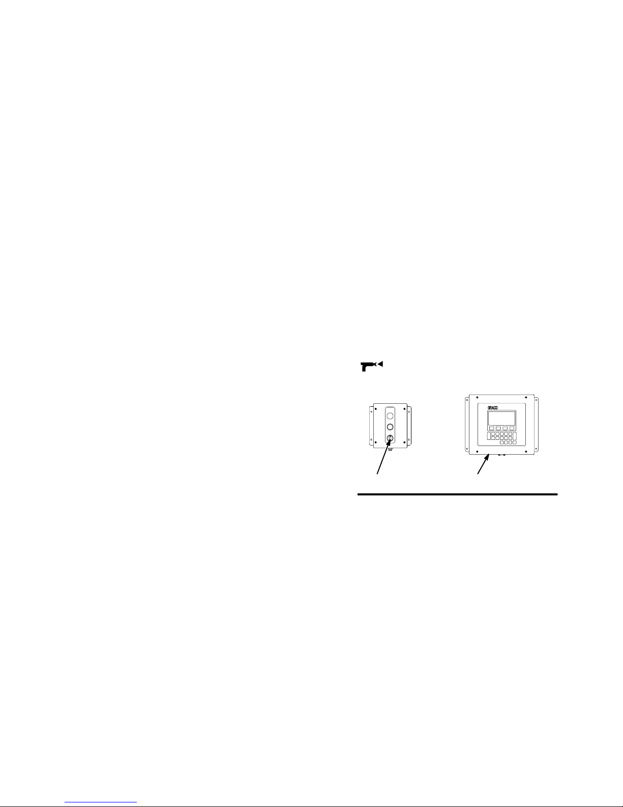
1. To begin operation, the operator enters the desired
ratio and other parameters through the User
Interface (BB) and turns the operator switch (AA)
to MIX .
Operating Cycle
The 3K fluid manifold consists of four separate fluid
supply lines for Component A, B, C, and the flushing
material. The Component A, B, and C supply lines
have the following parts to individually control the flow
of the three materials. Refer to Fig. 2.2.
Fluid filters (DA, DB, DC)
Check valves (EA, EB, EC)
Flow meters (FA, FB, FC)
Dispense valves (GA, GB, GC)
The dispense valves control the entry of the components into the integrator chambers. The flow meters
monitor the exact fluid volumes being dispensed and
send electrical pulses to the controller. The controller
monitors these pulses and signals the solenoids to turn
the dispense valves on or off accordingly (based on
the target volumes calculated by the controller).
Fig. 2.1
AA BB
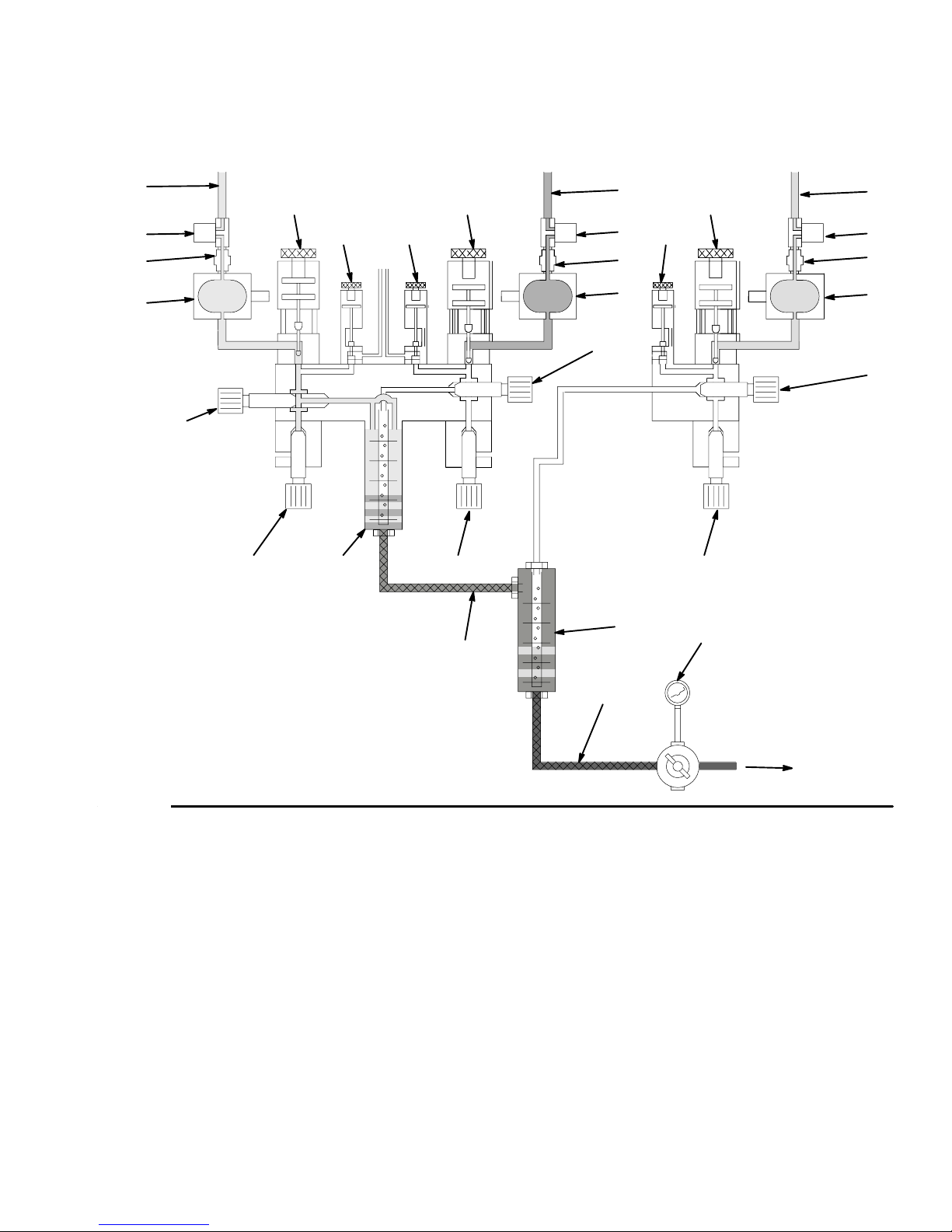
2. When the operator triggers the spray gun, the
controller sends a signal to activate the solenoid
valve for the component A dispense valve (GA).
See Fig. 2.2.
3. The component A dispense valve (GA) opens and
Component A begins to flow into the first integrator
chamber (L). When the correct quantity is dispensed (based on the calculated target value), the
component A dispense valve closes. See Fig. 2.2.
2–6
Overview
Page 17
How the PrecisionMix II 3K Works
Functional Diagram – Component A Dispense
Component A Component BComponent C
A
A
G
A
D
A
E
A
F
A
J
A
K
A
H
C
H
L
C
G
C
K
C
C
D
H
C
E
C
F
C
J
N
B
G
B
B
K
Q
B
B
D
B
E
B
F
B
J
M
Fig. 2.2
KEY for Figs. 2.2, 2.3, and 2.4
Component A
A Supply Line, Component A
DAFluid Filter, Component A ,
100 mesh minimum
EACheck Valve, Component A
FAFlow Meter, Component A
GADispense Valve, Component A
HAPurge Valve (usually air), Component A
JAFluid Shut-off Valve, Component A
KARatio Check Valve, Component A
Component C
C Supply Line, Component C
DCFluid Filter, Component C,
100 mesh minimum
ECCheck Valve, Component C
FCFlow Meter, Component C
GCDispense Valve, Component C
HCPurge Valve (usually solvent),
Component C
JCFluid Shut-off Valve, Component C
KCRatio Check Valve, Component C
P
Component B
B Supply Line, Component B
DBFluid Filter, Component B,
100 mesh minimum
EBCheck Valve, Component B
FBFlow Meter, Component B
GBDispense Valve, Component B
HBPurge Valve (usually solvent),
Component B
JBFluid Shut-off Valve, Component B
KBRatio Check Valve, Component B
Other
L First Integrator
M First Static Mixer
N Second Integrator
P Second Static Mixer
Q Fluid Meter
R Fluid Supply to Gun
R
TI0085B
Overview 2–7
Page 18
How the PrecisionMix II 3K Works
Functional Diagram – Component B Dispense
Component A Component BComponent C
A
A
G
A
D
A
E
A
F
A
J
A
K
A
H
C
H
L
C
G
C
K
C
C
D
H
C
E
C
F
C
J
N
B
G
B
B
K
Q
B
B
D
B
E
B
F
B
J
M
Fig. 2.3
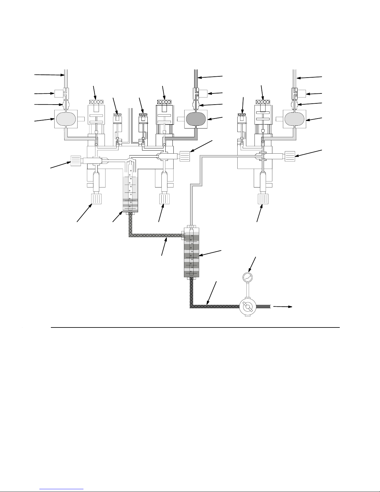
4. The controller sends a signal to activate the solenoid valve for the component B dispense valve
(GB). See Fig. 2.3.
P
R
TI0087B
5. The component B dispense valve (GB) opens and
Component B flows into the second integrator
chamber (N). The fluid is lined up proportionately
with the previously-dispensed Component A and C
dose. The component B dispense valve closes
when the target volume for Component B is
reached. See Fig. 2.3.
2–8
Overview
Page 19
How the PrecisionMix II 3K Works
Functional Diagram – Component C Dispense
Component A Component BComponent C
A
A
G
A
D
A
E
A
F
A
J
A
K
A
H
C
H
L
C
G
C
K
C
C
D
H
C
E
C
F
C
J
N
B
G
B
B
K
Q
B
B
D
B
E
B
F
B
J
M
Fig. 2.4
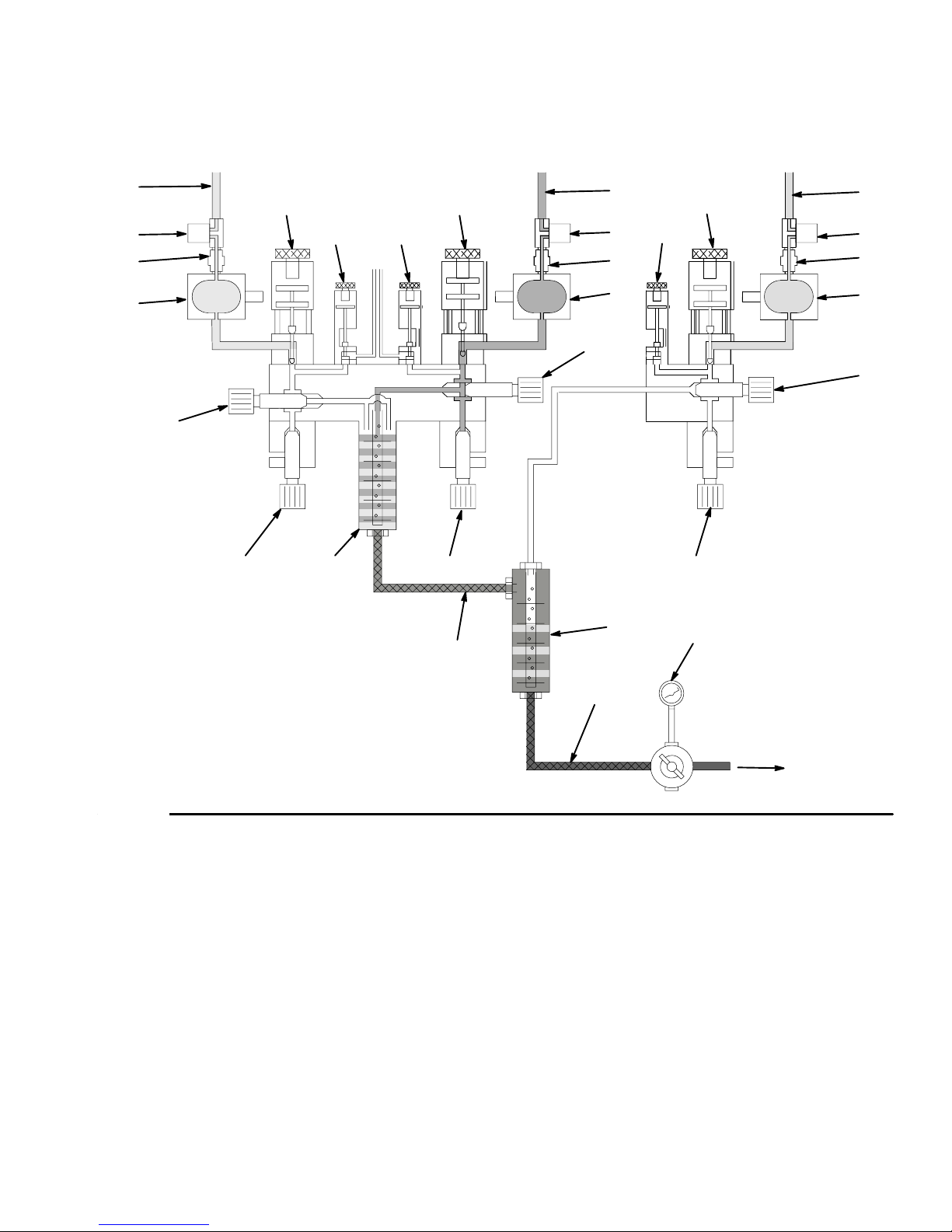
6. The component C dispense valve (GC) opens and
Component C flows into the first integrator chamber. The fluid is lined up proportionately with
Components A and B. The component C dispense
valve closes when the target volume for Component C is reached. See Fig. 2.4.
7. Components A and C flow into a static mixer (M),
where they are mixed. The mixture then flows into
the second integrator chamber (N). See Fig. 2.4.
8. The three components are given a homogeneous
blending as they pass through a second static
mixer tube (P).
P
R
TI0086B
9. The three components continue to be alternately
fed into the integrators as long as the gun is triggered. Output from the mixer tube to the spray gun
may be controlled by a fluid pressure regulator (Q).
After the trigger is released, if the gun is not triggered again within four minutes, the system will go
to an idle mode, which closes off the mix manifold.
When the gun is triggered again, the system will
continue the process where it left off. Operation
can be stopped at any time by energizing the
standby input or shutting off the main power
switch.
Overview 2–9
Page 20
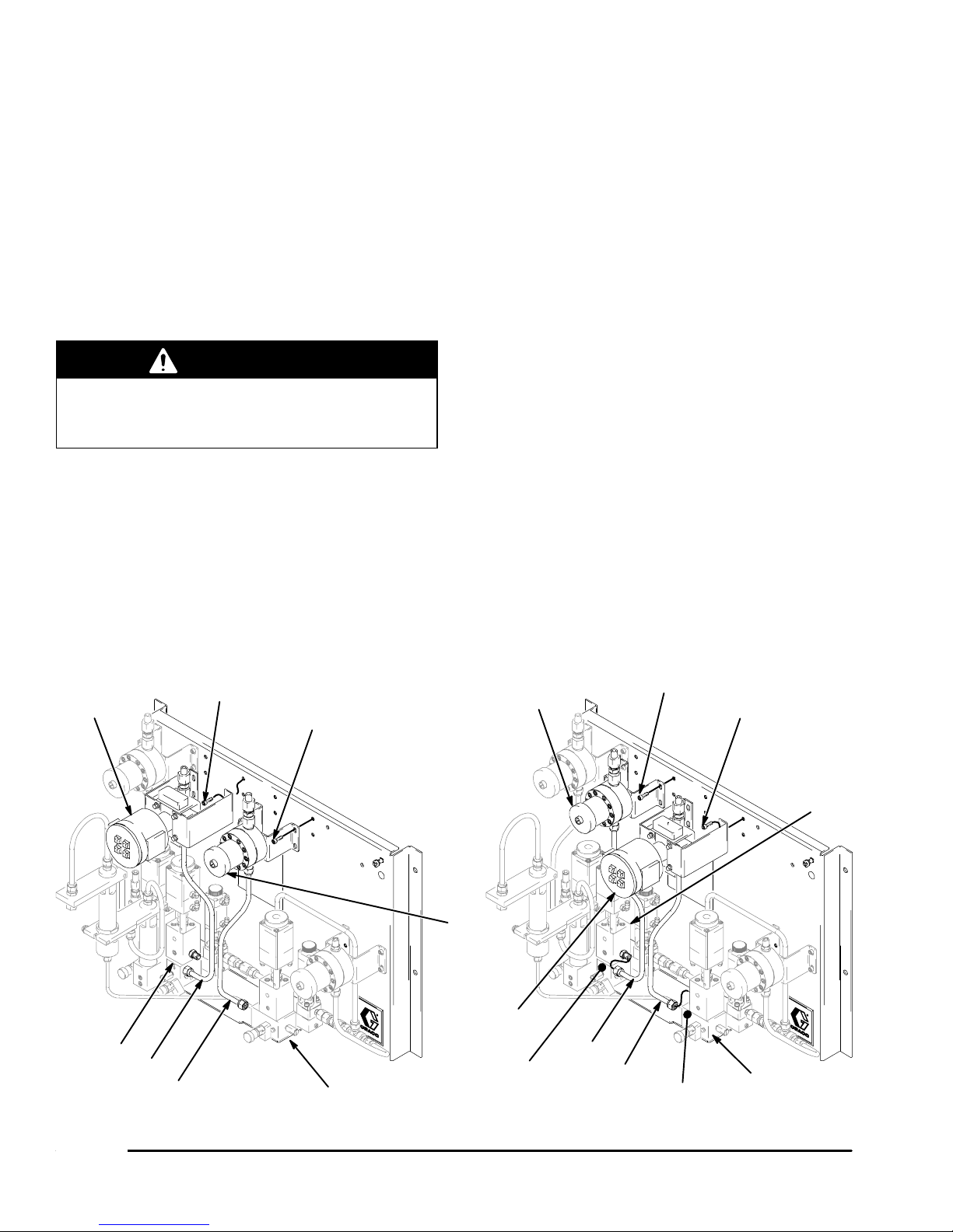
Changing the Mixing Order
The order in which the three components are mixed
depends on the characteristics of the materials being
used. In the standard configuration, Component A is
mixed with Component C first, then the blend of A and
C is mixed with Component B. The instructions in this
manual correspond with this mixing order.
To convert the PrecisionMix II 3K to a configuration
where Component A is mixed with Component B
before Component C is added, perform the following
steps.
WARNING
To reduce the risk of serious injury whenever you
are instructed to relieve pressure, always follow the
Pressure Relief Procedure on page 4–3.
1. Flush the system and relief the pressure.
2. Refer to Fig. 2.5. Unscrew the nut of the Component C tube (T) from the nipple at the dispense
valve (V).
4. Unscrew the nut of the Component B tube (W)
from the nipple at the dispense valve (Y).
5. Remove the screws (S) and take the Component
B meter (Z), bracket, and tube off the fluid panel.
6. Turn the tubes of both meters 180 so the nuts
face in the opposite direction.
7. Reinstall the Component B and C meters, in the
opposite locations.
8. Refer to Fig. 2.6. Disconnect the red air lines (R)
from the elbows at the Component B and C dispense valves and reconnect them to the opposite
dispense valve. Switch the green air lines (G) in
the same way.
9. Refer to Fig. 2.6. Disconnect the red air lines (R)
from the elbows at the Component B and C purge
valves and reconnect them to the opposite purge
valve. Switch the green air lines (G) in the same
way.
10. Using Part No. 196303 Label, relabel dispense
valve B to C and dispense valve C to B.
3. Remove the screws (S) and take the Component
C meter (U), bracket, and tube off the fluid panel.
S
U
V
T
W
Disassembly Reassembly
Fig. 2.5
S
Y
11. Reverse the wires on terminals 4271 and 4291.
Refer to Fig. 3.21, page 3–29.
Z
Z
U
W
Affix Label B Here
Affix Label C Here
2–10
S
S
T
V
Y
TI0223
Overview
Page 21
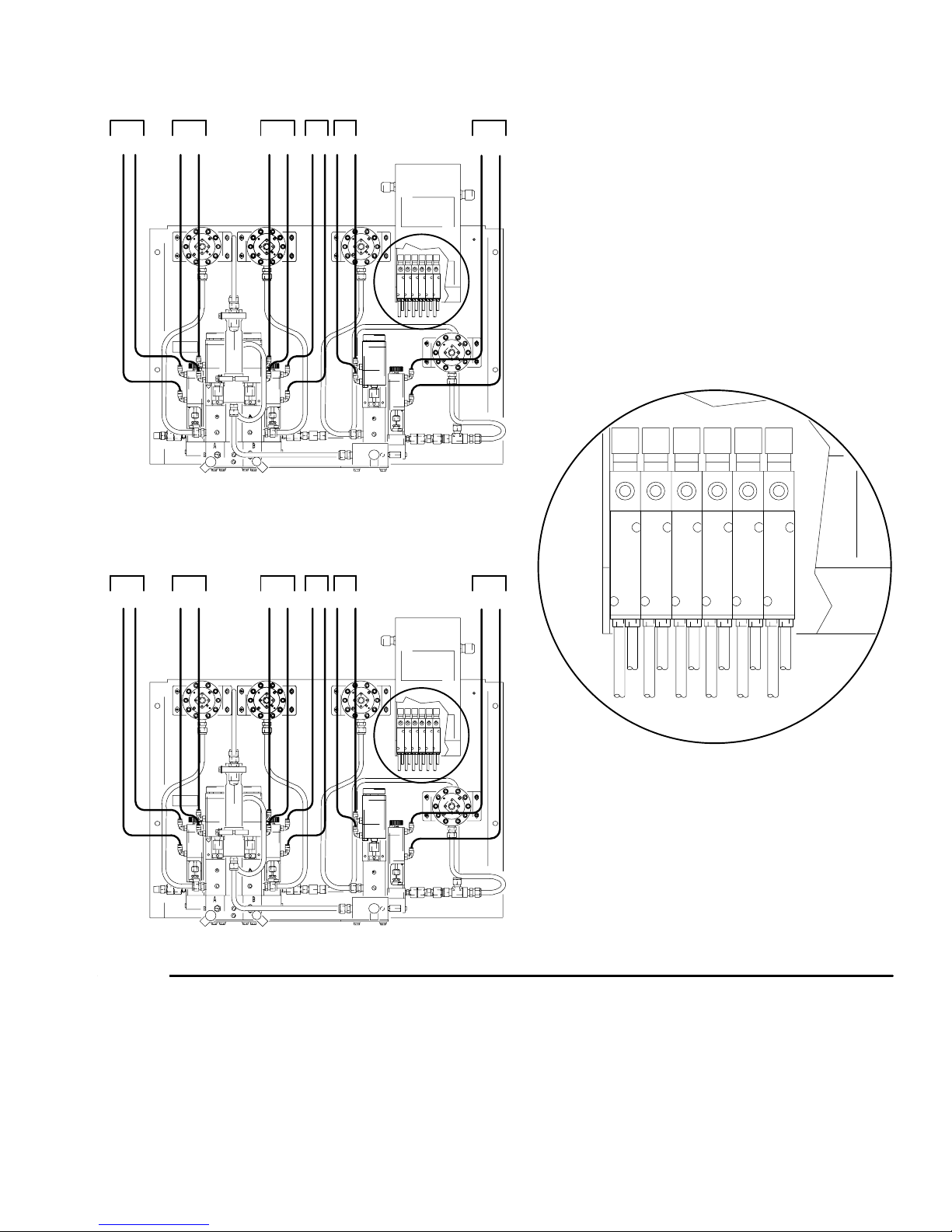
Changing the Mixing Order
AB
RGG GGG GRR RRR
Before Changing Component B and C Tubing Connections
CAP BPCP
AB
RGG GGG GRR RRR
After Changing Component B and C Tubing Connections
Fig. 2.6
CAP BP CP
ABCAPBPCP
GGGG G
RGRRR RR
Detail of Solenoid Box
TI0227
Overview 2–11
Page 22

Flow Control Overview
Flow Control is used to limit the flow of material to the
air spray gun to help avoid sags and runs in the finish
due to coatings being applied too thick or quickly and
to assure adequate coverage. Flow control can be
configured for use with a manual or automatic air spray
gun. Refer to Flow Control Setup, page 8–16.
The flow control module uses flow meters, fluid regulator, current to pressure (I/P) transducer, and the PrecisionMix II 3K controller to adjust and maintain the flow
of material to the air spray gun.
Flow control is an optional feature of the PrecisionMix 3K system. Your system must be
configured with flow control hardware and
software in order to use flow control. Detailed
information on using flow control is in other
sections of this manual.
Flow control is NOT for use with air-assisted or
airless spray guns.
System Requirements
The fluid feed system must have adequate volume and
pressure to supply the air spray gun. The Component
A, B and C fluid supply pressures need to be balanced. The fluid feed hose, gun nozzle and needle
size and travel must be sized and adjusted properly to
keep the flow control operating at its maximum efficiency.
General Operation Sequence
1. When the controller is first turned on, a pre-configured pilot air pressure is applied to the fluid regulator.
2. When the air spray gun is triggered, the controller
waits for the set delay time to elapse before it
starts monitoring the flow and making any necessary adjustments. The delay time is user selectable (typically 1–2 seconds) and helps assure the
fluid is moving at a normal rate before flow rate
adjustments occur.
3. When the fluid moves through the fluid lines, the
flow meter(s) monitors the flow and sends meter
pulses to the controller. These pulses are converted into flow measurements and checked
against the set values in the controller.
Flow Control Features
Ability to control one manual or automatic air
spray gun
Programmable maximum flow setpoint
Programmable lower flow control start value for
manual gun
Delayed activation of flow control after the gun is
triggered
Manual flow rate reset function, which can be
initiated from the in-booth Flow Control Station
An indicator light on the Flow Control Station to
show when the flow rate is resetting for manual gun
operation.
4. If the fluid flow falls outside the set values, the
controller sends a signal to adjust the fluid regulator to correct the flow. The flow is raised or lowered by the pilot air pressure from the current to
pressure (I/P) transducer. The greater the pilot air
pressure to the fluid regulator, the higher the fluid
pressure and the greater the fluid flow.
5. When the air spray gun is turned off, the flow
control holds the pilot air pressure value and does
not attempt to adjust fluid flow until the gun is
triggered again.
6. When the gun is triggered, the process of controlling the fluid flow continues.
2–12
Overview
Page 23
Flow Control Overview
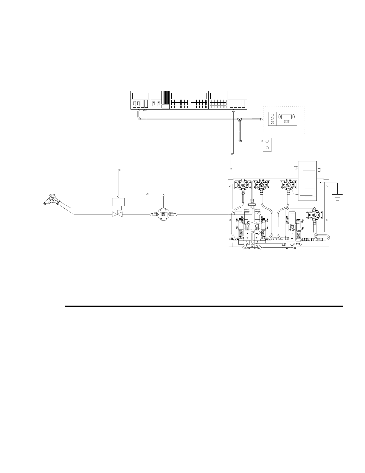
One Gun Flow Control Using a Flow Meter in the Mixed Material Line
Fig. 2.7 shows a one gun system that is using a flow meter, installed in the mixed material line, to monitor fluid flow
to the gun. Using a flow meter in the mixed material line, rather than monitoring fluid flow with the component A, B,
and C flow meters, provides a faster response to changes in the flow rate setpoint.
PrecisionMix II 3K Controller Panel
User Interface with
Color Change
RS–485
External Analog Setpoint
(use optional)
Current to
Pressure
Transducer
Fig. 2.7
Typical Installation of One Gun Flow Control Using a Flow Meter in the Mixed Material Line
4 to 20 mA Analog In
Flow Control Station
4 to 20 mA Analog Out
Flow Meter Signal
I/P
Fluid Regulator
Flow Meter
(Optional)
Fluid Panel
TI0162
Overview 2–13
Page 24
Flow Control Overview
Flow Control Components
(Refer to Fig. 2.7)
Flow Meter
Digital pulses are sent by the flow meters to the controller to provide fluid flow rate information.
Fluid Regulator
The flow control regulates the fluid flow to a pre-programmed flow rate by adjusting the fluid regulator. The
fluid regulator uses a pneumatic pilot pressure from a
current to pressure (I/P) transducer to open and close
the regulator needle.
Current to Pressure (I/P) Transducer
An adjustable pneumatic signal is required for the
controller to regulate the fluid flow. The current to
pressure transducer provides this signal. The controller
outputs an analog current signal that varies from 4
milli-amps to 20 milli-amps and the transducer
changes the milli-amp signal to a 1–100 psi (7–700
kPa, 0.1–7 bar) pneumatic signal. The pneumatic
pressure signal is applied to a fluid pressure regulator,
which controls the output fluid pressure to the air spray
gun.
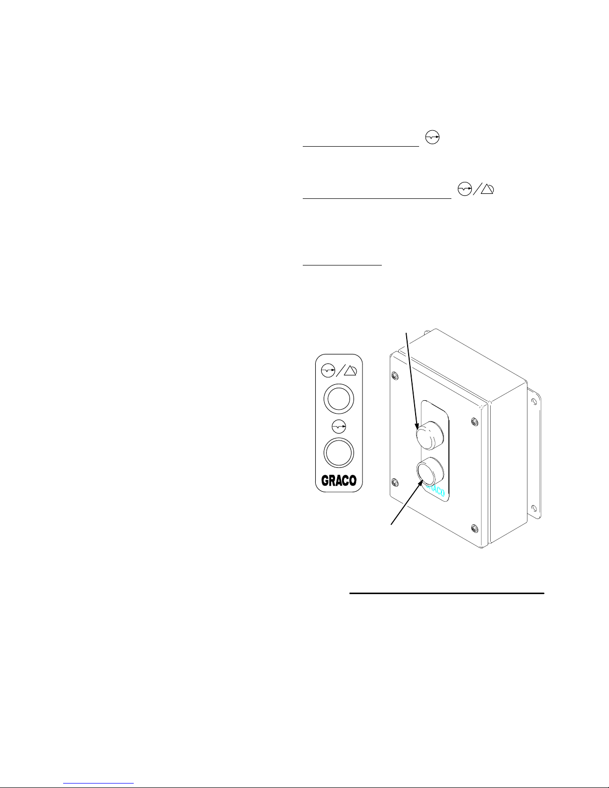
Flow Control Station
The Flow Control Station consists of a Flow Control
Reset/Warning light and Flow Control Reset button,
which are used with manual air spray guns to manually
initiate flow control reset.
Flow Control Reset Button
Pressing the reset button will cause the flow control
system to calibrate the flow rate to the current setpoint.
Flow Control Reset/Warning Light
The controller activates the Reset/Warning light when
the flow control system is resetting flow rate (solid
light) or when a flow control alarm condition occurs
(flashing light––flow rate is outside the set tolerance).
Flow Rate Alarms
Wait for the system to automatically calibrate the flow
rate or manually reset the flow rate by pressing the
reset button.
Flow Control Reset/
Warning Light
PrecisionMix II 3K Controller
The controller can be configured to control and display
the fluid control information, including setpoint, actual
flow, milli-amp output values to the I/P transducer,
system parameter, and I/O conditions. The controller
will indicate when the system is operating within flow
control tolerance and when it is not.
Fig. 2.8
Flow Control
Reset Button
Flow Control Station
9003A
2–14
Overview
Page 25
Flow Control Overview
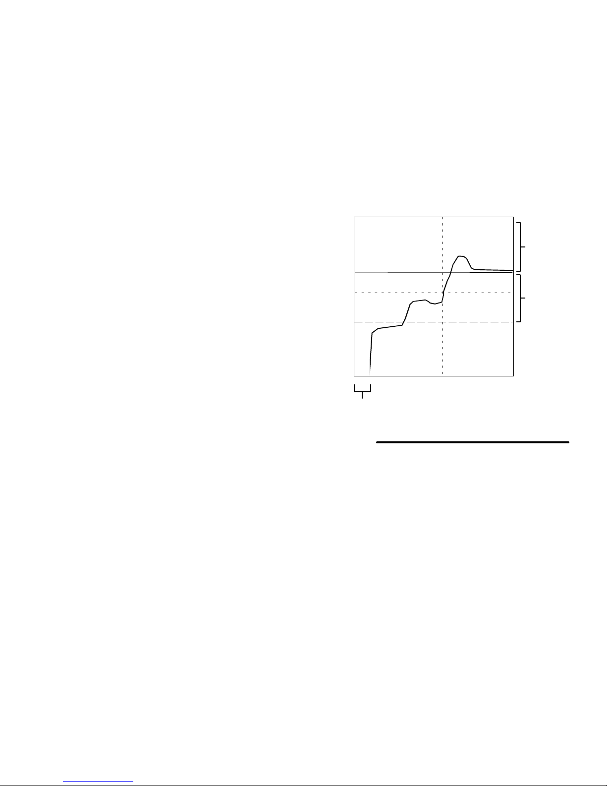
Flow Control Parameters (Refer to Fig. 2.9)
The following flow control parameters are entered from
either the User Interface or from digital input:
Setpoint Source – Specifies the source of the
flow limit value as User Interface, network or analog
input (refer to page 8–18).
Analog Scaling – If analog is the source of input,
the scaling for analog input must be set. The setting
is used to calculate the relationship between the
flow rate and a 4–20 mA input signal (refer to page
8–18).
Flow Rate Setpoint – Sets the value for the
desired flow rate. Flow control monitors and calibrates flow rate based on this value and the other
parameters (refer to page 9–9 or 9–16).
Delay Time – Sets the time that flow control waits
after the gun is triggered before starting to monitor
the flow rate. This allows time for the fluid to quickly
reach the setpoint and avoid unnecessary alarms or
corrections (refer to page 8–19).
Flow Control Low Limit – This value is only used
with manual guns and is always entered from the
User Interface (refer to page 9–9). The flow control
stops making adjustment if the flow rate falls below
the difference of setpoint and the “Low Limit”
volume. The warning alarm output will be on when
the actual flow rate falls out of this tolerance for 5
seconds. This helps the system allow for periodic
partial triggering (feathering) of a hand gun without
adjusting the flow rate.
If the setpoint is changed, the low limit will change
accordingly.
Example – If the setpoint is 500 cc/min. and the low
limit is 100 cc/min.:
The flow control will stop making adjustments
when the flow rate falls below 400 cc/min.
Changing the setpoint to 300 cc/min. will
change the low limit value to 200 cc/min.
Alarm
Tolerance
Flow Rate Setpoint
Flow
Delay Time
Fig. 2.9
Low Limit
Gun “feathered”,
No Flow Control
NOTE: Graph shown for hand gun flow control.
Full Flow Control
Time
Alarm
Tolerance
Overview 2–15
Page 26

Using Recipes/Color Change
There are three modes of operation relating to the
changing of recipes: No Color Change, Integrated
Color Change, and Integrated Color Change with
Queue. Refer to page 8–22. The controller logic
decides whether or not to allow a chosen recipe
change to occur. The criteria for allowing a recipe
change are as follows:
1. The new recipe must contain valid data for the
desired ratio, flow meter K-factors, tolerance, and
pot life times.
2. An active alarm must not exist in the system.
3. An Integrated Color Change can not already be in
progress.
4. The recipe number must not be greater than the
number of recipes configured to run on the system.
5. The input device used to change the recipe value
must be configured as the recipe input device
(User Interface, Network, I/O, or Operator Station).
6. When “No Color Change” is selected, the operator
switch on the Operator Station must be in the
A color change may be performed with the operator
switch in the Mix or Standby position. If the
operator switch is in the Mix position, the system
will be ready for immediate spraying after a color
change. The green light on the Operator Station will
blink while a color change is in operation. The green
light indicates that the system is busy and is not ready
for spraying.
Mix/Load Volumes
If mix/load volumes are configured for the system, the
fill portion of the color change may continue after the
color change has timed out. This feature may be used
in conjunction with a gun flush box to make sure that
the desired volume of material is loaded into the system. The system keeps track of the volume that is
mixed during the fill portion of the color change. If the
mix/load volume is not reached, then the system will
continue to fill until the volume is reached (the operator
switch needs to be in the Mix position for this to
occur automatically). Setting the mix/load volume to
zero will disable the mix/load volume feature.
Standby
position.
No Color Change
The system will boot up for the first time with color
change turned off. In this mode, color changes are
performed manually. The recipe number is changed
through the User Interface, Network, I/O, or Operator
Station. The operator must manually dump and purge
the old material from the system and then load the new
material into the system.
Integrated Color Change
The Integrated Color Change mode of operation
automatically performs the tasks necessary to execute
a color change. This is a time-based mode that is
configurable by the user. Refer to page 8–21. The
timing of the color change is configured in one of four
color change sequences. The color change
sequences contain start times and timer duration for
the devices that are controlled during a color change.
Each recipe is then assigned one of the four color
change sequences for its operation.
Recipe Zero
Recipe zero is considered the “Purge Down” recipe.
The purpose of this recipe is to allow the user to purge
out the material lines and the mixed material lines
without loading a new color. A typical use for recipe
zero is at the end of a shift. The operator performs a
color change to recipe zero and the lines are cleaned
out to prevent hardening of catalyzed material between
shifts. Multiple Purge Downs may also be performed if
the lines are not sufficiently clean. Another Purge
Down is triggered by pressing the Enter key on the
Operator Station or by setting the the color change bit
on the I/O high.
NOTE: Recipe 0 has a unique Purge Sequence 0 to
allow for end of shift or production shutdown. If you are
using a solvent meter, any additional solvent used in
the recipe 0 purge cycle will not be included in the
solvent totals. It is important to configure Purge Sequence 0 to flush all materials clean in one purge
cycle, to maintain accurate solvent use records.
Continued on the next page.
2–16
Overview
Page 27

Using Recipes/Color Change
Integrated Color Change – continued
The devices that are controlled by the Integrated Color
Change Sequences are as follows.
Purge Valves: The Integrated Color Change
Sequence typically starts by purging out the old mixed
material. The purge can be further defined by setting
the total purge time, the purge time for the first cycle,
the purge time for the last cycle, and the individual
purge times for the three possible purge valves. The
beginning of the purge can be delayed to allow time for
the gun triggers to activate. Refer to page 8–23.
Mix Valves: The sequence fills the hoses with the new
mixed material after the system has finished purging.
The target mix parameters are calculated after the
purge is completed, before the mix begins. The user
defines the mix (fill) time duration for the Color Change
Sequence. Refer to page 8–23.
Dump Valves: The dump valves open immediately
when the Color Change Sequence begins. The user
then configures how long these valves stay open. The
purpose of these valves is to allow the unmixed A, B,
and C component materials to dump from the system
before entering the mix manifold. Refer to page 8–24
and 8–26.
Special Outputs 1, 2, 5, and 6: The special outputs
are optional outputs that the user can configure for
their particular application. Each of these valves can
be turned on and off up to four times during a color
change sequence. Refer to page 8–28.
Specials 1 and 2 are pneumatic outputs, while Specials 5 and 6 are electrical outputs.
Integrated Color Change with Queue
The Integrated Color Change with Queue mode of
operation runs in a similar fashion to the standard
Integrated Color Change mode. The difference
between the two modes is that the Queue parameters
override the normal color change parameters during
the color change. Five data sets can be set up in a
queue and sent to the controller individually. Refer to
page 6–7. A queue data set consists of the following
five parameters.
1. Sequence Number – The number for the color
change sequence that will be used for the new
color.
2. Recipe Number – The recipe number that will be
used for the new color.
3. Color Valve Component A (Resin) – The number
corresponding to the component A color valve
chosen for the new color.
Solvent Valves: The Solvent valves open immediately
when the Color Change Sequence begins. The user
then configures how long these valves stay open. The
purpose of these valves is to push the unmixed A, B,
and C component materials through the dump valves
and clean the hoses for the next material. Refer to
page 8–24 and 8–26.
Gun Triggers 1–2: The gun triggers are electrical
outputs that can be configured to turn on and off up to
two times. These outputs are typically wired to the
spray guns triggers to allow automatic purging and
filling. Refer to page 8–27.
4. Color Valve Component B (Catalyst) – The
number corresponding to the component B color
valve chosen for the new color.
5. Color Valve Component C (Reducer) – The
number corresponding to the component C color
valve chosen for the new color.
A Queue Color Change is triggered by pressing the
Enter key on the Operator Station or by setting the
Color Change Bit on the I/O of the controller. The data
set values on the top of the queue will be used for the
Color Change. When color change is complete, the
top level of the queue is erased and all of the other
data sets move up one level on the queue.
Overview 2–17
Page 28

Using Recipes/Color Change
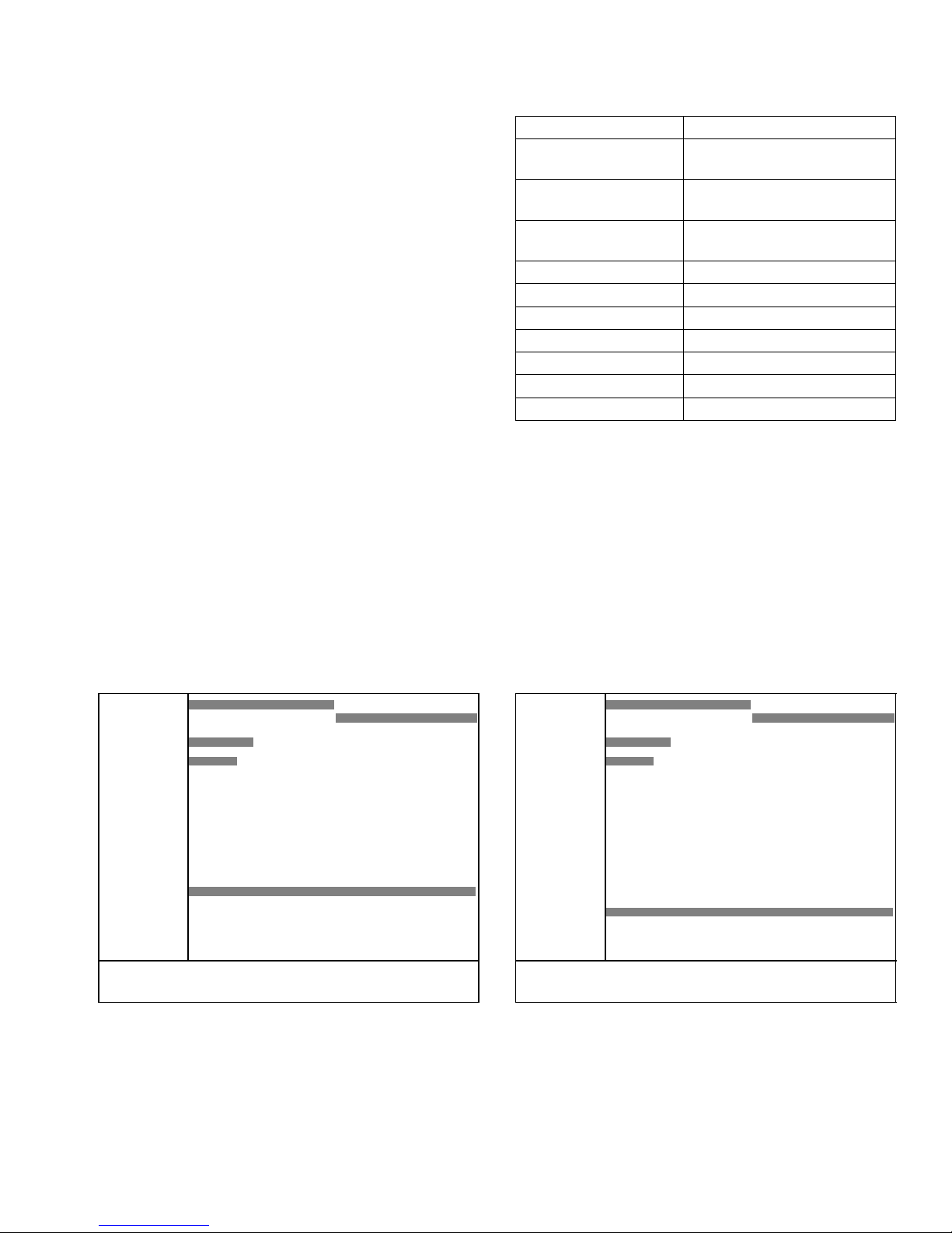
Color Change Sequences
There are four color change sequences that can be set
up to control how a color change will operate. These
sequences can be viewed on the User Interface in a
graphical fashion. A typical color change sequence
looks as follows.
Color Change Graph Screen
1. PURGE
MIX**
2. A DUMP
3. A SOLV
4. B DUMP
5. B SOLV
6. C DUMP
7. C SOLV
8. GUN1 TG
9. GUN2 TG
10.SPEC 1
11.SPEC 2
12.SPEC 5
13.SPEC 6
0 Sec 40.0
Color Chg Seq 1. Enter Function (1-13) 01
Sequence 1:
Purge time = 20 Seconds
Mix time = 20 seconds
Component A Dump time = 7 seconds
Component A Solvent time = 5 seconds
Gun 1 time = 40 seconds
Total Sequence Time = 40 seconds
The color change sequence begins by closing all of the
color change valves. Then the dump valve for Component A (resin) will immediately open, as well as the
solvent valve on the color stack. This will allow solvent
to flow into the fluid lines, through the flow meter, and
out through the dump valve.
The color change solvent valve stays open for 5 seconds, then it closes and the new color valve, associated with the new recipe, will open. The dump valve
remains open for two seconds after the new color
valve is opened, to allow the new color to fill the fluid
line and flush out the remaining solvent. The dump
valve is open for a total of 7 seconds.
In parallel with the dumping and filling of the fluid lines,
a purge is occurring through the mix manifold and
mixed material lines. The purge always starts at the
beginning of a color change sequence. The above
sequence triggers Gun 1 for the entire sequence. This
allows the purge to flush solvent through the mix
manifold and mixed material lines and out through the
gun. After 20 seconds, the purge is complete.
The system then begins to mix new material. The
system mixes for 20 seconds until the mix manifold
and the mixed material lines are full of new material.
This sequence is a 40 second long operation.
NOTE: When using automatic spray guns or gun flush
boxes, you must specify trigger times for each gun.
The screen shown above reflects the use of manually
triggered spray guns.
2–18
Overview
Page 29
Using Recipes/Color Change
Changing from One Color Change
Sequence to Another
It is possible to perform a color change from a recipe
associated with one color change sequence to a recipe
that is associated with another color change sequence.
In this case the system automatically uses the old
sequence for dumping and purging and the new
sequence for loading and mixing. This type of color
change is useful in applications where one material
tends to purge and load more quickly than another.
When switching from one sequence to another, there
are two transition points that determine which
sequence is being used at a given time. The first
transition point occurs when the solvent valve for the
color change stack closes. The second transition point
is when the purge is complete. The table at right lists
the outputs associated with the transition points.
An example of a color change from one sequence to another is as follows.
Transition Point Output
Color Stack Solvent
Component A Closes
Color Stack Solvent
Component B Closes
Color Stack Solvent
Component C Closes
Purge Ends Mix
Dump Valve Component A
Dump Valve Component B
Dump Valve Component C
Gun 1 Trigger
Gun 2 Trigger
Special 1
Special 2
Special 5
Special 6
Sequence 1:
Purge time = 20 Seconds
Mix time = 20 seconds
Component A Dump time = 7 seconds
Component A Solvent time = 5 seconds
Special 1 on time = 0 seconds
Special 1 time = 40 seconds
Total Sequence Time = 40 seconds
Color Change Graph Screen
1. PURGE
MIX**
2. A DUMP
3. A SOLV
4. B DUMP
5. B SOLV
6. C DUMP
7. C SOLV
8. GUN1 TG
9. GUN2 TG
10.SPEC 1
11.SPEC 2
12.SPEC 5
13.SPEC 6
0 Sec 40.0
Color Chg Seq 1. Enter Function (1-13) 01
Sequence 2:
Purge time = 40 Seconds
Mix time = 40 seconds
Component A Dump time = 13 seconds
Component A Solvent time = 10 seconds
Special 2 on time = 0 seconds
Special 2 time = 40 seconds
Total Sequence Time = 80 seconds
Color Change Graph Screen
1. PURGE
MIX**
2. A DUMP
3. A SOLV
4. B DUMP
5. B SOLV
6. C DUMP
7. C SOLV
8. GUN1 TG
9. GUN2 TG
10.SPEC 1
11.SPEC 2
12.SPEC 5
13.SPEC 6
0 Sec 80.0
Color Chg Seq 1. Enter Function (1-13) 01
Overview 2–19
Continued on the next page.
Page 30

Using Recipes/Color Change
Changing from One Color Change
Sequence to Another – continued
Actual valve times:
Purge time = 20 seconds
Mix time = 40 seconds
Component A Dump time = 8 seconds
Component A Solvent time = 5 seconds
Special 1 on time = 0 seconds
Special 1 time = 20 seconds
Special 2 on time = 20 seconds
Special 2 time = 40 seconds
Total Sequence Time = 60 seconds
Actual Valve Times
1. PURGE
MIX**
2. A DUMP
3. A SOLV
4. B DUMP
5. B SOLV
6. C DUMP
7. C SOLV
8. GUN1 TG
9. GUN2 TG
10.SPEC 1
11.SPEC 2
12.SPEC 5
13.SPEC 6
0 Sec 60.0
Color Chg Seq 1. Enter Function (1-13) 01
2–20
Overview
Page 31

3
Installation
Installation
3–1
Page 32

Installation3–2
Page 33

Typical Installation
WARNING
FIRE, EXPLOSION, AND ELECTRIC
SHOCK HAZARD
Installing and servicing this equipment
requires access to parts which could
cause an electric shock or other serious
injury if the work is not performed properly.
Do not install or service this equip-
ment or perform any of the following
installation and adjustment procedures unless you are trained and
qualified.
Comply with all applicable local, state, and
national fire, electrical, and other safety regulations.
WARNING
FLAMMABLE OR TOXIC
VAPOR HAZARD
Provide fresh air ventilation to avoid the
buildup of flammable or toxic vapors. Do
not operate the spray gun unless ventilation fans are operating. Follow all national, state, and local codes regarding air
exhaust velocity requirements.
NOTE:
Reference numbers and letters in parentheses in
this manual’s text refer to the numbers and letters
in the illustrations.
Be sure all accessories are adequately sized and
pressure-rated to meet the system’s requirements.
The Typical Installations shown in Figs. 3.1 and 3.2
are only a guideline for selecting and installing
system components and accessories, and are not
an actual system design. Contact your Graco
distributor for assistance.
KEY for Figs. 3.1 and 3.2
NOTE: The typical installation drawings (Figs. 3.1 and 3.2) show all possible system options. Your system may not include all these options.
A Alarm
B Controller
C Solenoid Bank for color change, 8 or
16 valves
D Solenoid Bank for catalyst or reducer
change, 8 valves
E Air Regulators
F Transducer
G Solenoid Box for gun flush box,
1 & 2 guns
H Gun Flush Box
J Flow Control
K Fluid Regulator, air operated
L Atomizing Air Shutoff Valve, air piloted
M Color/Resin Change Valves
N Fluid Panel
P Solenoid Box for fluid panel
Q Operator Station
R Operator Station with color change
S Flow Control Station
T User Interface (also available as a
remote interface, see page 3–10)
U Catalyst Change Valve
Installation
3–3
Page 34

Typical Installation
NON-INTRINSICALLY SAFE
TI0172
H
Key
Electrical
Pneumatic
Fluid
NOTE: See page 3–3 for
key to letter references
Gun Flush Box Cable
Flow Control Meter Cable
D
C
User interface is also available
as a remote interface, see
page 3–10.
1
F
U
Flow Control I/P Cable
Air In
M
Fluid Line To Gun
Component B
Component C
Solenoid Air
Atomizing Air
Component A
Purge Air
Resin Dump
E
G
L
J
K
P
Fluid Hose
N
S
1
Solenoid Power Cable
Solenoid Network Cable
T
B
A
Fig. 3.1
Solenoid Box Cable
Connector
Network PC
or Printer Cable
HAZARDOUS AREA
NON-HAZARDOUS AREA
Operator Station Cable
R
Q
Installation3–4
Page 35

Typical Installation
INTRINSICALLY SAFE
TI0225
H
Key
Electrical
Pneumatic
Fluid
NOTE: See page 3–3 for
Gun Flush Box Cable
Flow Control Meter Cable
CD
key to letter references
User interface is also available
as a remote interface, see
page 3–10.
1
F
Flow Control I/P Cable
Fluid Line To Gun
G
L
K
J
U
Component B
Component C
Solenoid Air
Air In
Atomizing Air
Component A
Purge Air
P
Fluid Hose
N
S
Resin Dump
M
E
Solenoid Power Cable
Solenoid Network Cable
AB
Fig. 3.2
Installation
1
T
Solenoid Box Cable
HAZARDOUS AREA
NON-HAZARDOUS AREA
Operator Station Cable
Connector
Network PC
or Printer
Cable
R
Q
3–5
Page 36

Fluid Supply Requirements
Common fluid supplies include pressure tanks, circulating lines, and pail or drum pumps. The fluid supply
should be capable of supplying enough pressure to
deliver a flow rate 1.5 times the maximum desired flow
rate.
If the Flow Control system is installed, it is very important to balance the fluid pressures of the Component
A, B and C fluid supplies to be within 2 psi (14 kPa, 0.1
bar) of each other at the fluid outlet.
The fluid supply must be free of pressure spikes, which
are commonly caused by a pump stroke changeover.
If necessary, install pressure regulators on the fluid
inlets to the PrecisionMix II 3K to reduce the fluid
supply pressure. Contact your Graco distributor for
information on fluid pressure regulators.
Circulating Lines
For maintenance and safety, you must install a ball
valve between each supply line and the
PrecisionMix 3K.
Installation3–6
Page 37

Mounting Components
The controller, color change panel, and fluid panel can
be wall mounted or installed on Part No. 241501 Stand
Mounting Kit. If the Stand Mounting Kit was ordered
with the system, the parts were mounted to the stand
at Graco. The Gun Flush Box can be wall, stand, or
drum mounted in the spray booth.
NOTE:
Refer to Figs. 3.1 and 3.2 for non-hazardous versus
hazardous location equipment requirements.
Refer to Fig. 3.3 through 3.6 for dimensions and
mounting hole layouts.
For Wall Mounting
Mount the components to a wall, as follows:
1. Ensure that the wall and mounting hardware are
strong enough to support the weight of the equipment, fluid, hoses, and stress caused during
operation.
Operator Station
(without integrated color change)
Depth: 3.25 in.
(83 mm)
8 in.
(203 mm)
6 in.
(152 mm)
6.75 in.
(171 mm)
Operator Station
(with integrated color change)
Depth: 3 in.
(76 mm)
8 in.
(203 mm)
11 in.
(279 mm)
11.75 in.
(298 mm)
6 in.
(152 mm)
6 in.
(152 mm)
2. Mark the mounting holes on the wall at a convenient height for the operator, using the equipment
as a template.
Color Change Panel: In order to use the
standard supplied fluid hose, the color change
panel must be mounted within 12 in. (305 mm)
of the fluid panel. Contact your Graco distributor for other available fluid hoses.
Operator Station or Flow Control Station:
Mount the station(s) inside the spray booth, at
a convenient location for the operator to access and use.
Flow Control Station
Depth: 3.25 in.
(83 mm)
(203 mm)
Fig. 3.3
6 in.
(152 mm)
8 in.
6.75 in.
(171 mm)
6 in.
(152 mm)
Continued on the next page.
9042A
Installation
3–7
Page 38

Mounting Components
For Wall Mounting – continued
Remote User Interface: If a remote User
Interface is used, mount it at a convenient
location for the operator to view and use.
Gun Flush Box: Install the gun flush box in
the spray booth. Locate it as far away from the
spray or application point as possible to help
avoid getting over-spray on it.
Gun Flush Solenoid Box: Install the gun
flush solenoid box in the non-hazardous area,
within 25 ft. (7.6 m) of the gun flush box. 100
ft. (30.5 m) of cable is provided, which connects the solenoid box with the controller.
3. Drill the mounting holes in the wall and install
anchors as needed.
4. Bolt the equipment securely to the wall.
Controller
Depth: 9 in.
(229 mm)
24 in.
(610 mm)
30 in.
(762 mm)
Remote User Interface
Depth: 3.75 in.
(95 mm)
11 in.
(279 mm)
Gun Flush Box
Depth: 9 in.
(229 mm)
(229 mm)
Gun Flush Solenoid Box
Depth: 3.25 in.
(83 mm)
12 in.
(305 mm)
9 in.
(229 mm)
12.75 in.
(324 mm)
14 in.
(356 mm)
9 in.
8 in.
(203 mm)
Fig. 3.4
22.5 in.
(572 mm)
28.5 in.
(724 mm)
TI0165
Fig. 3.5
6 in.
(152 mm)
6.75 in.
(171 mm)
6 in.
(152 mm)
9042A
Installation3–8
Page 39

Mounting Components
Stand Mounting Kit 241501
1. Select the desired location for the mounting stand.
Be sure to leave sufficient space around the
equipment for operator access, routing of hoses
and cabling, and ventilation.
56 in.
(1422 mm)
22 in.
(559 mm)
55.25 in.
(1403 mm)
30 in.
(762 mm)
28.75 in.
(730 mm)
2. Drill holes in the floor, using the mounting stand
base as a template, and install anchors as needed.
3. Secure the mounting stand to the floor.
19 in.
(483 mm)
Color Change Panel
Depth: 9 in.
(229 mm)
Fig. 3.6
Fluid Panel
Depth: 17.4 in.
(442 mm)
28.75 in.
(730 mm)
Dimensions and Mounting Holes
11 in.
(279 mm)
10 in.
(254 mm)
15 in.
(381 mm)
20.56 in.
(522 mm)
70 in.
(1778 mm)
TI0170
Installation
3–9
Page 40

System Installation
NOTE:
All options ordered on configured systems are
electrically tested at the factory and shipped connected from Graco.
It is recommended that all cables routed in the
spray booth and high traffic areas be enclosed in
conduit to prevent damage from paint, solvent, and
traffic.
Refer to the Electrical Connection table and
diagram, page 3–29, for wiring connections.
Install the Controller and User Interface
(Code A)
The controller is available with a panel mount user
interface or a remote user interface.
1. If you are using a remote user interface (T), Part
No. 194372 standard cable (C1) is provided to
connect the remote interface (T) to the controller
(B). The 9-pin D-SUB cable is 50 ft. (15.2 m) long.
See Fig. 3.7.
B
T
C1
TI0165
Fig. 3.7
2. Provide power to the controller, using conduit to
protect the wiring.
3. Ground the controller to a true earth ground. See
Grounding the System on page 3–30.
Installation3–10
Page 41

System Installation
Power Requirements
The Precision Mix II control is designed to operate with
120 Vac or 220 Vac input power. See Fig. 3.8 for the
wiring connections.
It is possible for voltage brown out conditions to cause
the Precision Mix II control to go into a memory failure
mode. If the power being supplied to the system is not
free of excessive dips an uninterruptable power supply
(UPS) or a power conditioner will need to be supplied.
The Precision Mix II control is already equipped with a
surge suppressor, adding one will not be necessary.
The basic requirements for purchasing a UPS or
power condition are as follows:
L1 L2 or Common
Ground
1. Purchase one rated for the desired input voltage
(120 Vac or 220 Vac).
2. Purchase one with a minimum output current of
125 Watts.
3. Purchase one that is rated for industrial use and
the maximum temperature conditions of the installation site.
NOTE: It is not recommended to mount either a UPS
or power conditioner inside the Precision Mix II control.
Fig. 3.8
L1 L2
Installation
3–11
Page 42

System Installation
Install the Fluid Panel (Code E) with Fluid
Meters (Code F)
A non-intrinsically safe fluid panel (Code E–1) is available for installing in a non-hazardous area. Refer to the
typical installation drawing on page 3–4.
WARNING
FIRE AND EXPLOSION HAZARD
The controller must be configured with
the proper barriers for it to be used with
a fluid panel installed in a hazardous
area. A non-intrinsically safe system
must be installed as shown in Fig. 3.1,
page 3–4.
An intrinsically safe fluid panel (Code E–2) is available
for installing in a hazardous area. Refer to the typical
installation drawing on page 3–5.
NOTE:
The selected fluid meters (S1, S2, S3, S4) are
installed on the fluid panel at the factory.
2. In certain situations, the cable (C6) may need to
be disconnected and reconnected to route the
cable as desired. If this is necessary follow the
steps below and refer to the Electrical Connec-
tion table and diagram, page 3–29.
Non-intrinsically Safe Fluid Panel Cable Wiring
a. Connect the cable wires to the terminals in the
controller.
b. Connect the cable wires to the terminal blocks
in the solenoid box.
Intrinsically Safe Fluid Panel Cable Wiring
a. Connect the cable wires to the barriers in the
controller.
See page 10–15 for a pneumatic schematic of the
fluid panel.
1. 50 ft. (15.2 m) of cable (C6) is supplied, connecting the fluid panel solenoid box (P) and the PrecisionMix II 3K controller (B). See Fig. 3.9.
3
2
S
S
P
4
N
S
TI0165
Fig. 3.9
B
1
S
C6
b. Connect the cable wires to the terminal blocks
in the solenoid box.
c. All wires must be connected to the terminal
blocks and barriers. All shields must be connected to the ground terminal of the appropriate barrier.
3. A cable is factory connected between the solenoid
box and meters to the meters. Bring the free end
of the cables into the solenoid box and connect the
wires to the terminal blocks.
4. Ground the fluid panel to the same true earth
ground used for the controller. See Grounding
the System on page 3–30.
Installation3–12
Page 43

System Installation
Install the Air Control Kit
If you have ordered the color change, the air control kit
is installed at the factory. Refer to Install the Optional
Color Change Panel, page 3–14.
1. 25 ft. (7.6 m) of air line is provided with the air
control kit (E). See Fig. 3.10.
2. Connect a minimum 1/2 in. (13 mm) main air
supply line to the air inlet.
1/2” npt
Air Inlet
E
Fig. 3.10
Be sure the supplied cable (C5) can reach the PrecisionMix II 3K controller (B). 100 ft. (30.5 m) of cable is
supplied, pre-connected to the operator station. The
cable is pre-stripped and has ferrules assembled. See
Fig. 3.11.
B
C5
Fig. 3.11
TI0165
Q
R
Install the Operator Station (Code J)
There are two types of operator station: with integrated
color change (R) and without integrated color
change (Q).
NOTE: It is recommended that the cable be enclosed
in conduit to prevent damage from paint, solvent, and
traffic inside the spray booth. Cut the cable to the
length needed, or coil the excess neatly in an out-ofthe-way location where it will not be damaged.
Installation
3–13
Page 44

System Installation
Install the Color/Catalyst/Reducer Change
Valves and Solenoids (Code K and L)
If color/catalyst/reducer change valves are ordered,
the valves along with the necessary solenoid valves
and the air control kit will be factory installed on the
color change panel (C). Fig 3.12 shows both color,
catalyst, and reducer valves and their solenoids
mounted on the panel.
1. See Fig. 3.12 and 3.13. All fluid and pneumatic
connections are factory completed. The air lines
may be shortened if desired.
GRD
+24V
GRD
–24V
COM
SHIELD
COM
2. Power (P) and network (N) cables, connecting the
color change panel with the controller (B), are
installed at the factory. The cables are 50 ft.
(15.2 m) long. They may be shortened at the
controller end only.
3. Ground the color change panel to the same true
earth ground used for the controller and the fluid
panel. See Grounding the System on page 3–30.
B
P
N
C
P (Ref)
Fig. 3.12
N (Ref)
TI0171TI0167
Electrical Connections
Installation3–14
Page 45
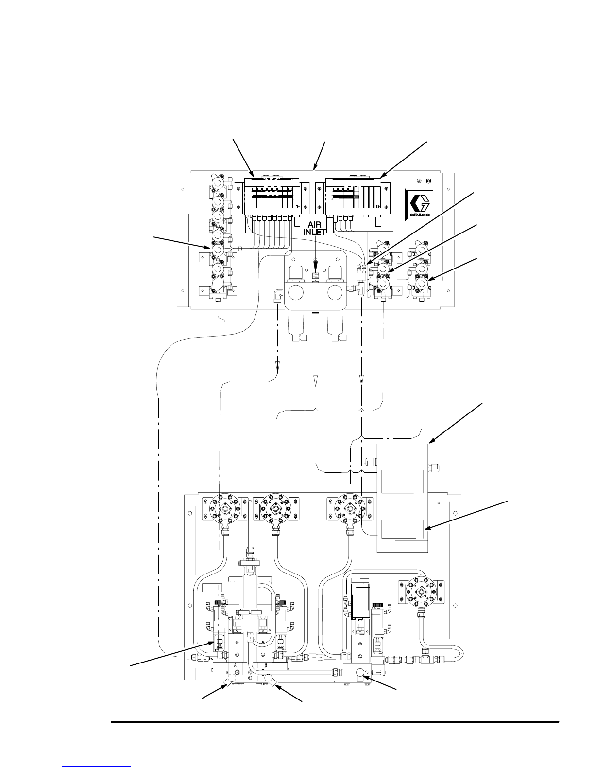
System Installation
Install the Color/Catalyst/Reducer Change
Valves and Solenoids (Code K and L) –
continued
Component A
Color Change
Valve Stack
Stack No. 1
Solenoid Bank
Color Change Panel
Atomizing Air
Solenoid Air
Stack No. 2 and 3
Solenoid Bank
Component C
Component B
Splitter
Component C
Stack No. 2
Component B
Stack No. 3
Solenoid Box
Component A Dump
Purge Valve
Component A Dump Valve
Fig. 3.13
Installation
Air and Fluid Connections
Purge Air
Component A
Solenoid Bank
Component B Dump Valve
Component C Dump Valve
3–15
Page 46

System Installation
Install the Gun Flush Box and Solenoid Box (Code M, N and P)
NOTE:
See Gun Flush Box Manual 309277 for gun flush
box adjustment and parts information.
See page 10–16 for a pneumatic schematic of the
gun flush box.
1. See Fig. 3.17. Install the gun flush box (H) in the
spray booth. Locate the Gun Flush Box as far
away from the spray or application point as possible to help avoid getting over-spray on it.
2. Install the gun flush solenoid box (G) in the nonhazardous area, within 25 ft. (7.6 m) of the gun
flush box. 100 ft. (30.5 m) of cable (C9) is provided, connecting the solenoid box with the controller (B).
3. Connect two feet (0.6 m) of straight pipe or tubing
(T) between the Gun Flush Box fluid outlet (O) and
an enclosed waste container (W). See Fig. 3.14.
WARNING
TOXIC FLUID HAZARD
To reduce the risk of splashing, a minimum of two
feet (0.6 m) of straight pipe or tubing must be
connected between the Gun Flush Box and an
enclosed waste container for the solvent.
4. Electrically interlock the Gun Flush Box air supply
with the ventilators to prevent the box from operating when ventilating fans are not operating. Check
and follow all National, State, and Local codes
regarding air exhaust velocity requirements.
WARNING
TOXIC OR FLAMMABLE FUMES
HAZARD
To avoid hazardous concentrations of
flammable or toxic fumes, install the Gun
Flush Box in a properly ventilated spray
booth. Never operate the Gun Flush Box
unless ventilation fans are operating.
5. Use a clean, dry air supply; filtered to 10 microns.
Connect a minimum 3/8 in. (10 mm) air supply line
to the gun flush box solenoid box (G).
6. Install an atomizing air shutoff valve (L) in the
spray gun air supply line. See Fig. 3.17 or 3.18.
7. Connect an air line (A3) between the valve (L) and
the air flow switch (D).
O
T
W
Fig. 3.14
Continued on the next page.
Installation3–16
Page 47

System Installation
Install the Gun Flush Box and Solenoid Box (Code M, N and P) – continued
8. Connect another air line (A1) from the atomizing
air shutoff valve (L) to port S on the gun flush box.
See Fig. 3.15.
9. Connect 5/32” (4 mm) OD air tubes (A2) between
the gun flush solenoid box (G) ports and the gun
flush box (H) ports. Refer to the table below and
Fig. 3.15 for connection ports.
Gun Flush Box Air Tube Connections
Solenoid Box Gun Flush Box
Ports Description Ports Description
C Solenoid Output C Gun trigger cyl-
inder air (activates gun trigger)
A Pressure Switch A Return air for
the gun in the
box signal
P Air Supply P Supply air in
* S Safety interlock
(locks out the
atomizing air)
E Solenoid Ex-
haust – no connections required
No connections
required
Fig. 3.15
Fig. 3.16
Gun Flush Box Bottom View
Solenoid Box Bottom View
TI0469
* Connect to the atomizing air shutoff valve (L). See
Figs. 3.17 and 3.18.
Installation
3–17
Page 48

System Installation
Install the Gun Flush Box and Solenoid Box (Code M, N and P) – continued
B
C
C9
G
A2
(mounted to the
back of the fluid
panel solenoid box)
Fig. 3.17
One Gun Flush Box Installation
Non-Hazardous Area
Hazardous Area
D
A3
To Gun
L
A1
H
8990A
Installation3–18
Page 49

System Installation
Install the Gun Flush Box and Solenoid Box (Code M, N and P) – continued
Wire the second air flow switch through
1
terminal block #11 in the solenoid box
of the fluid panel.
C9
G1
C10
G
(mounted to the
back of the fluid
panel solenoid box)
Fig. 3.18
Two Gun Flush Box Installation
B
H
Non-Hazardous Area
Hazardous Area
A2
H1
A2
A1
Hazardous Area
D
A3
Non-Hazardous Area
A1
L
Non-Hazardous Area
Hazardous Area
D
1
A3
L
8990A
P–Mix
Fig. 3.19
Installation
Solenoid Box I
Terminal Blocks
Solenoid Box II
Terminal Blocks
TI0471
3–19
Page 50

System Installation
Install the Optional Flow Control
NOTE: Refer to the system electrical schematic,
Manual 309138, included with the system.
1. See Fig. 3.20. Install the fluid regulator (K) in the
spray booth, on the fluid supply line to the spray
gun. Locate the fluid regulator as close to the
spray gun as possible.
2. Install the I/P transducer (F) in the non-hazardous
area, but as close to the fluid regulator as possible.
Mount the transducer on a vibration free surface.
100 ft. (30.5 m) of cable (C12) is supplied, connecting the I/P transducer to the controller.
3. Connect a minimum 3/8 in. (10 mm) air supply line
to the I/P transducer (F).
4. The I/P transducer supply air must be a maximum
of 100 psi (0.7 MPa, 7 bar), free of oil or water,
and filtered to a minimum of 40 micron.
To Controller
C12
Fluid Connections
Figs. 3.1 and 3.2.
1. Connect the solvent supply line to the solvent inlet
on the fluid panel. If your system has color
change, make solvent connections to the color
change stack and the catalyst change stack.
2. Connect the resin supply line, catalyst supply line,
and reducer supply line to their respective inputs
on the fluid panel. The fluid supplies must have
consistent, non-fluctuating pressure through the
full flow rate range.
3. Connect a fluid hose between the spray gun and
the mixer outlet.
4. Connect an atomizing air hose from the air flow
switch to the spray gun.
Pressure Test and Solvent Flush the
System
Before operating the system, perform the Pressure
Test and Solvent Flush procedures on page 3–36.
See system assembly drawings on electrical schematic 309138 for more specific details.
Non-Hazardous Area
Hazardous Area
Fluid in
Fig. 3.20
Air in
F
Air out
Fluid out
K
9004A
Installation3–20
Page 51

System Installation
Digital Outputs
Terminal
Block
5171 Solvent A Valve The Solvent A Valve output opens the solvent valve for
5181 Solvent B Valve The Solvent B Valve output opens the solvent valve for
5191 Solvent C Valve The Solvent C Valve output opens the solvent valve
5201 Purge/Mix Load The Purge/Mix Load output indicates that the system
5211 Gun 1 Trigger On The Gun 1 Trigger On output is used as an input to a
5221 Gun 2 Trigger On The Gun 2 Trigger On output is used as an input to a
5231 Special 5 This output is not used for Non–Integrated Color
5241 Special 6 This output is not used for Non–Integrated Color
6171 Ratio Alarm Ratio Low, Ratio High, A Overdose, B Overdose, C
6181 Flow Rate Alarm Gun 1 Flow Control Off: Low Flow
6191 Flow Rate Alarm Gun 2 Flow Control Off: High Flow
6201 Potlife Alarm Gun 1 Potlife Alarm for Gun #1. Same as Non–Integrated Color Change.
6211 Potlife Alarm Gun 2 Potlife Alarm for Gun #2. Same as Non–Integrated Color Change.
6221 Purge/Load Interlock
6231 Purge Not Complete
6241 General Alarm All System Alarms: This includes all alarms included
Description Non–Integrated Color Change Function Integrated Color Change Function
Same as Non–Integrated Color Change.
purging. This valve is typically used with air.
Same as Non–Integrated Color Change.
purging. The valve is typically used with solvent.
Same as Non–Integrated Color Change.
for purging. The valve is typically reserved for special
applications.
The Purge/Mix Load output will be high
is purging or loading. This output will be high during a
purge or a fill using the mix load volume.
Gun Flush Box to automatically trigger the gun. This
output will turn on automatically (if gun flush boxes are
enabled) for purging and loading.
Gun Flush Box to automatically trigger the gun. This
output will turn on automatically (if gun flush boxes are
enabled) for purging and loading.
Change.
Change.
Overdose, A Dose Time, B Dose Time, C Dose Time.
Flow Control On: Gun 1 High Flow, Gun 1 Low Flow
Flow Control On: Gun 2 High Flow, Gun 2 Low Flow
Purge/Load Interlock, I/O Alarm, Invalid Recipe. Same as Non–Integrated Color Change.
Alarm
Purge Time Out, Purge Not Complete Same as Non–Integrated Color Change.
Alarm
for outputs 1–7, plus Memory Failure, Control Battery
Low, and Display Battery Low.
during an Integrated Color Change. It will
also be high if the system is being manual-
ly purged or filled.
The Gun 1 Trigger output may be turned
on or off via the programmable color
change sequences. It will also turn on if
the system is being manually purged or
filled.
The Gun 2 Trigger output may be turned
on or off via the programmable color
change sequences. It will also turn on if
the system is being manually purged or
filled.
The Special 5 output may be turned on or
off via the programmable color change se-
quences.
The Special 6 output may be turned on or
off via the programmable color change se-
quences.
Same as Non–Integrated Color Change.
Same as Non–Integrated Color Change.
Same as Non–Integrated Color Change.
Same as Non–Integrated Color Change.
Installation
3–21
Page 52

Component Electrical Connections
Terminal
Strip No. in
Main Controller
2041 Festo solenoid bank 115153 Blue Can Low
2051 Network communication Shield Shield Can network port
2061 White Can High Pin connector port
2021 Red 24 VDC
1082 Black Ground
2021 Festo solenoid bank 115150 White 24 VDC Power supply
1082 Power supply Blue Ground Pin connector port
None Pre-wired with connec-
None Pre-wired with connec-
Accessory/Option
Name
Color Change Festo Solenoid Stack
Graphic User Interface
tors
Printer Port
tors
Cable
Part
No.
194400 Pre-wired connectors
See
printer
option
Wire Color Function Barriers
Uncontrolled
Side
Barriers
Controlled
Side
Accessory Terminal
No.
Pre-wired connectors
PC Network Interface
3081 White/Blue Network B All other P-Mix 3K sys-
3091 Shield Network A
3101 Blue/White Ground
Operator Station
Barrier No. 3321 (factory wired)
3131 194477 Green Network A 1 3 A
3151 White Network B 2 4 B
Ground Shield/drain Ground PA/gnd Shield/drain
Barrier No. 3251 (factory wired)
2021 Red 24 VDC 1 3 “+24 VDC
1082 Black Common 2 4 Com
Ground Shield/drain Ground PA/gnd Shield/drain
tems on the network
Installation3–22
Page 53

Component Electrical Connections
Terminal
Strip No. in
Main Controller
4021 Component A Brown Signal 1 3 4021
1082 Black Common 2 4 1082
1082 Drain Shield PA/gnd Shield
4061 Component B Blue Signal 1 3 4061
1082 Black Common 2 4 1082
1082 Drain Shield PA/gnd Shield
4081 Component C Green Signal 1 3 4081
1082 Brown Common 2 4 1082
1082 Drain Shield PA/gnd Shield
5171 Solvent Component A Green Signal 1 3 5171
1082 Black Common 2 4 1082
1082 Drain Shield PA/gnd Shield
5181 Solvent Component B White Signal 1 3 5181
1082 Black Common 2 4 1082
1082 Drain Shield PA/gnd Shield
Accessory/Option
Name
Solenoids
Cable
Part
No.
Wire Color Function Barriers
Uncontrolled
Side
Barriers
Controlled
Side
Accessory Terminal
No.
5191 Solvent Component C Green Signal 1 3 5191
1082 Orange Common 2 4 1082
1082 Drain Shield PA/gnd Shield
Installation
3–23
Page 54

Component Electrical Connections
Terminal
Strip No. in
Main Controller
4251 Component A White/Red Signal 2 4 4251
1082 Black Ground PA/gnd 1082
2021 Red 24 VDC 1 3 2021
1082 Drain Shield/drain PA/gnd Shield
4271 Component B Blue/Red Signal 2 4 4271
1082 Black Ground PA/gnd 1082
2021 Orange 24 VDC 1 3 2021
1082 Drain Shield/drain PA/gnd Shield
4291 Component C Green/
1082 Blue Ground PA/gnd 1082
2021 Green 24 VDC 1 3 2021
1082 Drain Shield/drain PA/gnd 1082
Accessory/Option
Name
Meters
Cable
Part
No.
Wire Color Function Barriers
Uncontrolled
Side
Signal 2 4 4291
White
Barriers
Controlled
Side
Accessory Terminal
No.
4311 Flushing Material Brown/Red Signal 2 4 4311
1082 Black Ground PA/gnd 1082
2021 Yellow 24 VDC 2021
1082 Drain Shield/drain PA/gnd Shield
Air Flow Switch
5051 Gun 1 Trigger Green Signal 2 4 5051
2021 Red 24 VDC 1 3 2021
1000
5061 Gun 2 Trigger Yellow Signal 2 4 5061
2021 Red 24 VDC 1 3 2021
1000
Installation3–24
Page 55

Component Electrical Connections
Terminal
Strip No. in
Main Controller
6171 From
6201 Orange Potlife alarm Orange wire
1082 Yellow Ground Yellow wire
5111 065338 White Gun flush box interlock
5121 Green Gun flush box interlock
5221 Blue Gun trigger gun flush
5211 Orange Gun trigger gun flush
2021 Red 24 VDC 2021
1082 Black Common 1082
8041 Red Analog + input gun #1
8051 Black Analog – input gun #1
1082 Shield Signal Protection Field Source
1082 Shield Signal Protection Field Source
Accessory/Option
Name
Alarm
Gun Flush Box
Flow Control
Cable
Part No.
Alarm
Wire Color Function Barriers
Uncontrolled
Side
Gray Ratio alarm Gray wire
gun 1
gun 2
box 2 (auto dump)
box 1 (auto dump)
remote 0–20 Ma
remote 0–20 Ma
Barriers
Controlled
Side
Accessory Terminal
No.
5111 input +24 VDC
5121 input +24 VDC
5221 output +24 VDC
5211 output +24 VDC
Field Source
Field Source
2021 Red 24 VDC power to I/P
gun #1
8281 White 4–20 Ma signal I/P
gun #1
8291 Green I/P common gun #1 1
1082 Black I/P common gun #1 2
1082 Shield Signal protection Case
1082 Shield Signal protection Case
6
4
Installation
3–25
Page 56

Component Electrical Connections
Terminal
Strip No. in
Main Controller
7121 Security bypass Input +24 VDC discrete
7111 Spare Input +24 VDC discrete
7101 External process con-
7091 External process con-
7081 External process con-
7071 External process con-
7061 External process con-
7051 External process con-
6101 Spare
6121 Gun #2 Solenoid from
6111 Gun #1 Solenoid fro mI/
Accessory/Option
Name
Field Wiring Terminals
for Additional Interface Capabilities
troller
troller
troller
troller
troller
troller
Cable
Part
No.
Wire Color Function Barriers
Uncontrolled
Side
Recipe bit 5 Input +24 VDC discrete
Recipe bit 4 Input +24 VDC discrete
Recipe bit 3 Input +24 VDC discrete
Recipe bit 2 Input +24 VDC discrete
Recipe bit 1 Input +24 VDC discrete
Recipe bit 0 Input +24 VDC discrete
I/O (GFB)
O (GFB)
Barriers
Controlled
Side
Accessory Terminal
No.
Installation3–26
Page 57

Component Electrical Connections
Terminal
Strip No. in
Main Controller
6091 External process con-
6071 External process con-
6061 External process con-
6051 External process con-
5051 External solenoid Gun 1 trigger Input +24 VDC
5061 External solenoid Gun 2 trigger Input +24 VDC
5071 Remote alarm External alarm Input +24 VDC
5081 External process con-
5091 External process con-
5101 External process con-
6241 Spare
6231 Remote alarm Purge not complete
6221 Spare
6211 Remote alarm Potlife alarm gun 2 Output +24 VDC
6201 Remote alarm Potlife alarm gun 1 Output +24 VDC
6191 Remote alarm Flow alarm: high flow/
6181 Remote alarm Flow alarm: low flow/
6171 Remote alarm Ratio alarm Output +24 VDC
5241 Special Output +24 VDC
5231 Special Output +24 VDC
5201 External process con-
Accessory/Option
Name
Field Wiring Terminals
for Additional Interface Capabilities
(continued)
troller
troller
troller
troller
troller
troller
troller
troller
Cable
Part
No.
Wire Color Function Barriers
Uncontrolled
Side
Flow control override Input +24 VDC discrete
Gun 1 flow rate control
reset
Mix Input +24 VDC discrete
Purge Input +24 VDC discrete
Abort reset Input +24 VDC discrete
Color change Input +24 VDC discrete
Print report Input +24 VDC discrete
alarm
gun 2
gun 1
Purge/mix load Input +24 VDC discrete
Barriers
Controlled
Side
Accessory Terminal
No.
Input +24 VDC discrete
Output +24 VDC
Output +24 VDC
Output +24 VDC
Installation
3–27
Page 58

Notes
Installation3–28
Page 59

Controller Terminal Block
CAUTION
If power and grounding connections are not done
properly, the equipment will be damaged and the
warranty will be voided.
Refer to Fig. 3.21.
Network SHLD
Network B
Network A
RSM B*
RSM*/Festo +24V
RSM*/Festo GND
Gun #2 Auto Selection for GFB
Gun #1 Auto Selection for GFB
Flow Control Override/Maximum Analog
Gun 2 Flow Control Reset
Gun 1 Flow Control Reset
Gun 1 Air Flow Switch Input
Gun 2 Air Flow Switch Input
Purge/Load OK Interlock Gun #1
Purge/Load OK Interlock Gun #2
RSM A*
CAN_H
CAN SHLD
CAN_L
CAN +24V
CAN GND
Security Bypass
(spare)
Recipe Bit 5
Recipe Bit 4
Recipe Bit 3
Recipe Bit 2
Recipe Bit 1
Recipe Bit 0
(spare)
Mix
Purge
External Alarm
Abort Reset
Color Change
Print Report
* RSM = Run screen monitor
NOTE: All signals labeled 1082 are GND.
All signals labeled 2021 are +24V.
Optional Terminal
Blocks for Flow Control
Fig. 3.21
Purge Not Completed Alarm (w/solvent meter option)
Purge/Load Interlock Not Ready Alarm
Flow Too High Alarm/Flow Rate Alarm Gun 2
Flow Too Low Alarm/Flow Rate Alarm Gun 1
Flow Meter Input Solvent
Flow Meter Input C
Flow Meter Input B
Flow Meter Input A
Remote Analog Input Setpoint #1 +
Remote Analog Input Setpoint #1 –
Remote Analog Input Setpoint #2 +
Remote Analog Input Setpoint #2 –
Analog Output to I/P #1 +
Analog Output to I/P #1 –
Analog Output to I/P #2 +
Analog Output to I/P #2 –
General Alarm
Potlife Alarm Gun 2
Potlife Alarm Gun 1
Ratio Alarm
Special #6
Gun 2 Trigger Output
Gun 1 Trigger Output
Mix Solenoid Output B
Mix Solenoid Output A
Special #5
Purge/Mix Load
Solvent C Valve
Solvent B Valve
Solvent A Valve
(spare)
Not Used
TI0240
Installation
3–29
Page 60

Ground the System
See Fig. 3.22.
WARNING
FIRE, EXPLOSION, AND ELECTRIC
SHOCK HAZARD
To reduce the risk of fire, explosion, or
electric shock:
The PrecisionMix II 3K system must
be electrically connected to a true
earth ground; the ground in the electrical system is not sufficient.
All wires used for grounding must be
10 gauge minimum.
A qualified electrician must complete all ground-
ing and wiring connections and check the
resistance as instructed on page 3–31.
Refer to your local code for the requirements for
a “true earth ground” in your area.
Also read and follow the warnings on page 1–3.
Ground the PrecisionMix II 3K system as instructed
here and in the individual component manuals. A
ground wire and clamp, part no. 222–011, is available
from Graco. Grounding instructions are continued on
page 3–31.
Controller
Connect the controller’s green-yellow ground terminal
block to the NEMA enclosure’s grounding lug. Connect
a ground wire from the enclosure to a true earth
ground. The controller enclosure and the manifold
mounting surface must be connected to the same true
earth ground point.
PrecisionMix II 3K Manifold
The mounting surface for the PrecisionMix II 3K manifold must be electrically connected to the same true
earth ground point as the controller enclosure. Different ground points may cause current to flow through
the meter cables, causing incorrect signals.
Color Change Panel
The mounting surface for the color change valves and
solenoids must be electrically connected to the same
true earth ground point as the controller enclosure.
Different ground points may cause current to flow
through the network cables, causing incorrect signals.
Operator Station
Ground the operator station to a true earth ground.
Flow Control Station
Ground the flow control stations to a true earth ground.
Gun Flush Boxes
Ground the gun flush boxes to a true earth ground.
Gun Flush Solenoid Boxes
Ground the gun flush solenoid boxes to a true earth
ground, or mount them on a grounded surface.
Flow Meters
Connect the meter cables as instructed in the manual
for your flow meter. Failure to properly connect the
grounded conductor and shield may cause incorrect
signals.
Feed Pumps or Pressure Pots
Use a ground wire and clamp to electrically connect
the pumps or pots to a true earth ground. See your
separate pump or pressure pot manual.
Air and Fluid Hoses:
Use grounded hoses only.
Spray Gun
Follow the spray gun manufacturer’s grounding
instructions.
Fluid Supply Container
Ground the container according to your local code.
Object Being Sprayed
Ground the object according to your local code.
All Solvent Pails Used When Purging
Ground the solvent pails according to your local code.
Use only metal pails, which are conductive, placed on
a grounded surface. Do not place the pail on a nonconductive surface, such as paper or cardboard, which
interrupts the grounding continuity.
Maintain Grounding Continuity When Purging Or
Relieving Pressure
Follow the instructions in your separate gun manual for
safely grounding your gun while purging.
Installation3–30
Page 61

Ground the System
2
1
KEY
1
Controller
Controller’s Ground Lug
2
Controller Enclosure Ground Wire; must be connected to same
3
true earth ground [6] as the fluid panel is connected to .
4
Ground Wire connection point for the fluid panel ground wire.
5
Fluid Panel Ground Wire; must be connected to same true earth
ground [6] as the controller is connected to.
3
8
7
5
4
6
True Earth Ground; check your local code for requirements.
7
Ground Wire connection point for the color change panel ground
wire.
8
Color Change Panel Ground Wire; must be connected to same
true earth ground [6] as the controller and fluid panel are conĆ
nected to.
6
Fig. 3.22
Check the Resistance
WARNING
FIRE, EXPLOSION, AND ELECTRIC
SHOCK HAZARD
To reduce the risk of fire, explosion, or
electric shock the resistance between
the PrecisionMix II 3K components and
true earth ground must be less than 1
ohm.
TI0163
Have a qualified electrician check the resistance
between each PrecisionMix II 3K component and the
true earth ground. The resistance must be less than 1
ohm. If the resistance is greater than 1 ohm, a different
ground site may be required. Do not operate the
system until the problem is corrected.
Installation
3–31
Page 62

Power-up Checklist
Power-up Steps
PrecisionMix II 3K System
Make sure the Operator Station switch is in STANDBY before turning on the system.
1. Ensure that the jumper position on the 24 VDC power supply is in the correct position for the main
supply voltage.
2. Ensure that the fuses are the correct value for the main supply voltage.
3. Turn on the main power switch.
4. Check that the DC ON LED on the power supply is lit.
5. Check that LEDs 1, 2, 3, and 4 on the controller interface module are lit. See Fig. 3.23.
6. Check that the CAN and RUN LEDs on the controller are lit, the ERR (error) LED is not lit, and the
RS232 LED is blinking. See Fig. 3.23.
7. Check that the OK LEDs on all the I/O modules are lit.
8. Check that the User Interface has powered up and is displaying the initial Run Monitor screen. See
page 6–3.
9. Check that all the lights on the Operator Station, including the alarm light, illuminate for about 1
second during power-up. If the Operator Station includes integrated color change, make sure that the
color change display does not remain at E2". See page 4–4.
Optional Flow Control
10. Check that the LEDs 1 and 2 on the analog interface module are lit. See Fig. 3.23.
11. Check the I/P transducer as instructed on page 3–34.
12. If flow rate setpoint is controlled from analog input, test the external 4–20 mA input signal as
instructed on page 3–35.
Installation3–32
Page 63

CP
Interface
Power-up Checklist
Step # 4
Fig. 3.23
Step #5 Step #6
Step #7 Step #10
Installation
3–33
Page 64

Power-up Checklist
Checking Flow Control I/P Transducers
NOTE: Only follow this procedure if a Flow Control
system is installed.
1. Turn on the main power on the PrecisionMix II 3K
controller.
2. Turn off the air supply to the I/P transducers.
W ARNING
The next test will use free-flowing air from the I/P
transducer. Make sure the area is safe for this test.
3. Remove the air line from the I/P transducer outlets. Turn on the air supply to the I/P transducer.
4. Go to the System Configuration Menu screen.
System Configuration Menu
SYSTEM CONFIGURATION Station: 00
MENU
1.LANGUAGE
2.STATION NUMBER
3.DISPLAY UNITS
4.RECIPES
5.POTLIFE TIMER
6.FLOW RATE LIMITS
7.SOLVENT METER
8.PURGE SEQUENCE
9.MIXED LOAD VOL.
10.GUNS SETUP
Select a menu item and press enter: > 12
11.MIX/PURGE
12.FLOW CONTROL
13.INTEGRATOR VOLUME
14.COLOR CHANGE
15.PASSWORD CHANGE
16.TIME AND DATE
17.DISPLAY SETUP
18.PRINT SETUP
19.AIR FLOW SWITCH
Flow Control Menu (FCMenu)
SYSTEM CONFIGURATION Station: 1
FLOW CONTROL: MENU
Select Flow Control Options to Edit:
1. Source of Flow Control Data
2. Analog Input Scaling Range
3. Force Analog Output
4. Delay Time to Start Flow Control
5. Flow Meter Location
> 3
7. Type number 3 for Force Analog Output
then .
FC1: Flow Control Force Output
SYSTEM CONFIGURATION Station: 1
FLOW CONTROL:FORCE OUTPUT
Select On to Begin Forcing the Outputs:
> ON
Enter a New Output Percentage to Force
the Flow Regulator:
Gun 1 = 100 %
5. Type number 12, for FLOW CONTROL, then .
C12: Flow Control
SYSTEM CONFIGURATION Station: 1
FLOW CONTROL OPTIONS
Select Flow Control Options:
1. OFF
2. Hand Gun Operation
3. Automatic Gun Operation
> 2
Press Enter to Accept Data and Edit
the Flow Control Options.
6. Type the number for the desired flow control option
then .
8. Select ON and enter 100% to force the fluid
regulator open. Maximum air pressure should flow
from the I/P transducer. Enter 0% to close the Fluid
regulator. There should be no air flow from the I/P
transducer.
9. Re-install the I/P transducer air lines.
Installation3–34
Page 65

Power-up Checklist
Testing Flow Control External 4–20 mA
Input Signal
NOTE: Only follow this procedure if a Flow Control
system is installed.
1. Select to display the Flow Rate Setpoint screen
(fourth screen) on the User Interface.
Flow Rate Setpoint
RUN MONITOR Recipe #: 1 Station: 1
00/00/00 00:00
Gun #1 Setpoint: 0000 cc/min
Flow Actual: 0000 cc/min
Rate Analog out: 00.0 mA
Setpoint in: 00.0 mA
Press Enter for a new Setpoint
2. Vary the 4–20 mA signal and note the Setpoint in
value changes on the screen.
For a maximum flow rate setpoint of 2000 cc/min.,
the scaling will be as follows:
20 mA signal = 2000 cc/min. Actual" display
on screen
10 mA signal = 1000 cc/min. Actual" display
on screen
4 mA signal = 0 cc/min. Actual" display on
screen
Installation
3–35
Page 66

Pressure Test and Solvent Flush Procedure
Pressure Test Component A
WARNING
NOTE: On systems with color change, perform steps 1
COMPONENT RUPTURE HAZARD
Do not exceed the maximum working
pressure of the lowest rated system
component. See the instruction manuals
of the individual PrecisionMix II 3K components for
their maximum working pressures.
through 6. On systems without color change, begin
with step 4.
With Color Change
1. Supply solvent pressure to the solvent flush port of
the color stack.
WARNING
INJECTION HAZARD
Spray from the gun, hose leaks, or ruptured components can inject fluid into
your body and cause extremely serious
injury, including the need for amputation. Splashing
fluid in the eyes or on the skin can also cause serious injury.
Do not stop or deflect fluid leaks with your hand,
body, glove, or rag.
Wear the appropriate protective clothing,
gloves, eyewear, and respirator.
Make sure all fluid lines are properly connected
before performing the pressure test or solvent
flush procedures.
NOTE: Perform all of the following steps before operating the PrecisionMix II 3K.
Test Color Valve Operation
1. Complete all steps of the System Installation
procedure.
2. Manually actuate the solvent solenoid valve (#1)
on the Component A side of the color change
panel. Repair any solvent leaks.
3. Manually actuate the component A dump solenoid
valve (#2) on the color change panel. Flush solvent through the color stack, meter, and component A dump valve until the solvent is clean and
free of air. Repair any leaks. Continue with step 4.
Without Color Change
4. Manually actuate the component A solenoid valve
(#2) in the solenoid box on the fluid panel. Repair
any leaks.
5. Trigger the spray gun into a grounded metal pail
until the solvent dispensed from the gun is clean
and free of air.
6. Open the ratio check valves and flush with solvent
until clean.
Pressure Test Component B and
Component C
2. Turn on main power and perform all power-up
checks. Refer to page 3–32.
3. Turn on the air supply. Manually activate each
solenoid valve on the color change panel and
observe the associated color change valve or
dump valve to verify that the valves are operating
properly.
4. Turn on the solvent supply to the flush valves and
the Component A, B, and C material supply.
Repair any leaks.
NOTE: For Component B and Component C, follow
the same procedure used for Component A.
Pressure Test the Solvent Lines
1. Manually actuate the solvent solenoid valve (#1)
on the Component A side of the color change
panel. Repair any solvent leaks.
2. Trigger the spray gun into a grounded metal pail
until the solvent dispensed from the gun is clean
and free of air.
Installation3–36
Page 67

4
Operation
Operation 4–1
Page 68

Operation4–2
Page 69

Pressure Relief Procedure
WARNING
INJECTION HAZARD
The system pressure must be manually
relieved to prevent the system from
starting or spraying accidentally. Fluid
under high pressure can be injected through the
skin and cause serious injury. To reduce the risk of
an injury from injection, splashing fluid, or moving
parts, follow the Pressure Relief Procedure
whenever you:
are instructed to relieve the pressure,
stop spraying,
check or service any of the system equipment,
install or clean the spray tip.
1. Set the operator switch to STANDBY .
2. Relieve fluid and air pressure at the component
and solvent feed pumps or pressure pots, as
explained in their separate instruction manuals.
3. Set the operator switch to MIX .
4. If using an electrostatic gun, make sure the electrostatic power is turned off.
5. Hold a metal part of the spray gun firmly to the
side of a grounded metal pail, and trigger the gun
to relieve fluid pressure.
6. Set the operator switch to STANDBY .
Stop production at any time by setting the operator
switch to STANDBY. If your stop time will not exceed
the pot life of Component A, B, or C, no additional
action is needed, except to relieve the system pressure. If your stop time will exceed the pot life, you must
purge the mixing system.
Operation 4–3
Page 70

Operator Controls and Indicators
There are two controller configurations:
Controller with panel mounted User Interface
Controller with remote User Interface
Both configurations have an Operator Station.
Operator Station (See Fig. 4.1 and 4.2)
The Operator Station consists of an operator switch,
print button, and alarm light. The station may also have
an optional Color Change Control.
NOTE: The operator switch and the color change
control portion of the Operator Station are enabled or
disabled during system configuration. See Recipe
Source selection, on page 8–6 and Mix/Purge Input
source selection, on page 8–11 for more information.
Operator Switch
There are three operator switch input settings: mix,
standby, and purge.
MIX
Setting the operator switch to mix starts the normal
operation (mixing and dispensing) of the system.
Clearing Alarms
When clearing alarms, do not leave the operator switch in the PURGE position for more than
2 seconds or the system will purge.
All alarms, except the Pot Life Alarm, can be cleared
by moving the operator switch momentarily to PURGE
, then back to STANDBY .
To start spraying again, turn the switch back to
MIX .
Alarm Light
Print Button
Color Change
Control
STANDBY
Setting the operator switch to standby stops the system.
PURGE
Setting the operator switch to purge causes the system to cycle between the air and solvent purge solenoid outputs to operate the air and solvent purge
valves. Purge will not initiate until two seconds after
the operator switch has been moved to the purge
position. This cycling can be either a function of time or
of volume if flow meters are connected to measure
volume.
Print Button
Pressing the print button will output a run report and
reset the job totals.
Alarm Light
The controller activates the alarm light when the
PrecisionMix II 3K has stopped operating because of
an alarm condition. The type of alarm will display on
the user interface.
Fig. 4.1
Operator
Fig. 4.2
Operator
Switch
Operator Station
with Color Change Control
Alarm Light
Print Button
Switch
Operator Station
without Color Change Control
Operation4–4
Page 71

Operator Controls and Indicators
Color Change Control
The current working recipe can be modified using the
arrow keys
Operator Station.
Key Function
Increase
Arrow
Decrease
Arrow
Return
Press to increase the recipe value by one
increment each time the key is pressed.
Press to decrease the recipe value by
one increment each time the key is
pressed.
Press to send the new recipe information
to the controller. The enter key also triggers a color change if one of the Integrated Color Change modes is selected.
and the enter key on the
Color Change Control
Display
Return
Key
When a new recipe is selected using the arrow keys,
two blinking periods
ing the new recipe information has been input, but the
enter key has not been pressed. The user has 5
seconds to press the enter key and accept the new
recipe before the display returns to the old recipe.
The function of the Color Change Control key entries is
dependent on which color change mode has been
selected; see the table below. See page 8–21 for
instructions on selecting the color change mode.
Color Change
appear on the display, indicat-
Function of Key Entries
Mode
No Color
Change:
Integrated Color
Change On:
Integrated Color
Change On With
Queue:
A new recipe may be selected
immediately by changing the
recipe value with the arrow keys
and pressing the enter key.
Selecting a new recipe with the
arrow keys and pressing the
enter key will start an integrated
color change. The green “Color
Change Active” light on the
Operator Station will blink until
the color change is finished.
Pressing the enter key will trigger the next integrated color
change from the queue. The
arrow keys are not active in this
mode. The green “Color Change
Active” light on the Operator
Station will blink until the color
change is finished.
Color
Change
Active
Light
Fig. 4.3
Operation 4–5
Arrow
Keys
Operator Station
with Color Change Control
Page 72

Operator Controls and Indicators
User Interface
The User Interface is a small terminal with a 16 x 40
character display and a keyboard for entering setup
parameters. The User Interface is available mounted in
NAVIGATIONAL KEYS
HOME Key: Press to go to the HOME screen.
See page 6–3.
PRINTER Key: Press to print pre-defined
report.
Screen Navigation Keys
PREVIOUS Key: Press to view the previous
screen.
NEXT Key: Press to view the next screen.
CANCEL Key: When in a configuration or
setup mode, press X to cancel a change that
was entered and revert back to the previous
data. When in run mode, press X to reset the
totalizers.
the controller door or as a remote station that can be
mounted as desired. See page 3–13. The operation of
the interface remains the same for both versions.
ENTER Key: Press to enter numerical data or
to enter data and move to the next field on
screens with multiple fields.
Selection Toggle Keys
INCREASE Key: Press to toggle up through
the selections for a data field.
DECREASE Key: Press to toggle down
through the selections for a data field.
Data Field Navigation Keys
DOWN Key: Press to move down a line of
data fields.
UP Key: Press to move up a line of data fields.
Fig. 4.4
NOTE:
If a number for an option is entered that is not
available, the User Interface will beep to indicate an
error. If the screen is exited while the error is present, the screen will automatically return to the
previous existing number that was entered.
Some configuration choices will affect what is
available for choices on related screens.
When an entry is accepted by the system, the
value will be highlighted.
Operation4–6
Page 73

Operation
Operating Checklist
Check the following list daily, before starting to operate
the system, to help ensure safe, efficient operation.
____ 1. All operators are properly trained to safely
operate the system.
____ 2. If using electrostatics, all operators are
properly trained to safety operate an electrostatic spray system. Operators must always
turn off the electrostatics (P) before placing
the spray gun in the Gun Flush Box.
____ 3. The system is thoroughly grounded and the
operator and all persons entering the spray
area are properly grounded. See Ground-
ing, page 3–30.
____ 4. The air lines are all connected to the Gun
Flush Box.
____ 5. The ventilation fans are operating properly.
____ 6. All the debris, including flammable liquids,
rags, and non-essential equipment, is removed from the spray area.
Mode Switch (See Fig. 4.5)
Make sure the mode switch is set to 1 (one) before
beginning normal operation of the system. The possible mode switch settings are as follows:
Switch Position Used For
A Controller download
B Disable printer
f Diagnostics (do not use in nor-
mal operation)
0 Operating system download
1 Default setting for normal opera-
tion
Mode Switch
____ 7. All flammable liquids in the spray booth are
in approved, grounded containers.
____ 8. All electrically conductive objects in the spray
area, including paint containers; Gun Flush
Box; and wash cans, are electrically
grounded and the floor of the spray area is
electrically conductive and grounded.
The PrecisionMix II 3K was tested with lightweight oil. To prevent contamination of your
fluids, thoroughly purge the system with solvent
as instructed in Purging the PrecisionMix II
3K System, page 4–11. Leave the solvent in
the system.
Fig. 4.5
Operation 4–7
Page 74

Operation
Purging the Ratio Check Valves
WARNING
PRESSURIZED EQUIPMENT HAZARD
To avoid splashing fluid in the eyes when
purging the ratio check valves:
Wear eye protection.
Only open the ratio check valves enough to
allow fluid to flow at a rate of 100 to 200 cc per
minute.
WARNING
INJECTION HAZARD
To reduce the risk of a serious injury
from injection or splashing fluid, follow
the Pressure Relief Procedure on page
4–3 whenever you are instructed to relieve the
pressure.
1. Relieve the system pressure.
2. Close Component A, B, and C fluid shut-off valves.
See Fig. 4.6.
3. Place a container under the Component B and C
ratio check valve dispense tube.
4. Turn on the solvent supply.
5. Open the Component C ratio check valve one-half
to one full turn.
KEY
A Dispense Valve Knob
B Purge Valve Knob
C Fluid Shut-off Knobs
D Ratio Check Valve Knob
A
B
A
B
CAUTION
The fluid shut-off valves and ratio check valves are
retained in their housings by mechanical stops that
prevent accidental removal of the valve stem while
the manifold is pressurized. Do not use a tool to
open or close the valve stems. If manual force
cannot turn the valve stems, the system pressure
must be relieved and the valve properly disassembled and cleaned to remove the resistance.
NOTE: Refer to Figs. 2.2, 2.3, and 2.4, pages 2–7
through 2–9, to understand the fluid paths that occur
during this procedure, which involves the manual
manipulation of the fluid shut-off valves and ratio check
valves.
D
D
Fig. 4.6
C
D
TI0173
C
TI0224
Operation4–8
Page 75

Operation
Purging the Ratio Check Valves
– continued
6. Press the manual override button (K) on the solvent solenoid valve, which is inside the PrecisionMix II 3K solenoid enclosure. Refer to Fig. 4.7.
Component C
Component B
Component A
Fig. 4.7
H
J
Solvent C Purge
Solvent B Purge
Solvent A Purge
K
TI0164
10. Fully open the component A fluid shut-off valve,
and open the component A ratio check valve
one-half to one full turn.
11. Press the manual override button (H) on the
solvent solenoid valve.
12. Purge the component A ratio check valve until
clean solvent flows from the check valve, then
close the valve.
13. Open the component B ratio check valve one-half
to one full turn.
14. Press the manual override button (J) on the solvent solenoid valve.
15. Purge the component B ratio check valve until
clean solvent flows from the check valve, then
close the valve.
16. Fully open the component B fluid shut-off valve.
7. Purge until clean solvent flows from the component C ratio check valve, then close the valve.
8. Open the component C fluid shut-off valve.
9. Trigger the spray device while pressing the manual
override button (K) on the solvent solenoid valve
until clean solvent flows from the gun.
17. At this point, component A, B and C ratio check
valves should be closed and all three fluid shut-off
valves should be fully open.
18. Purge the system as instructed on page 4–10 if
you are not loading paint into the system to start
production. If you are starting production, follow
the procedure on page 4–12.
Operation 4–9
Page 76
Operation
Purging the PrecisionMix II 3K System
WARNING
FIRE AND EXPLOSION HAZARD
To reduce the risk of fire, explosion and
serious injury when purging the PrecisionMix II 3K:
Be sure the entire system and flush-
ing pails are properly grounded.
Follow the instructions in your separate gun
manual for safely grounding your gun while
purging.
WARNING
INJECTION HAZARD
To reduce the risk of a serious injury
from injection or splashing fluid:
Follow the Pressure Relief Proce-
dure on page 4–3 whenever you
are instructed to relieve the pressure.
If you are using a high pressure gun*, remove
the spray tip before purging. Relieve pressure
before removing the spray tip.
Wear protective eyewear.
Use the lowest possible fluid pressure when
purging.
Purge the system during initial startup, at the end of
each workday, and before any break longer than the
pot life of the fluid.
Solvent may be used to purge all three components,
but this will result in longer purge sequences and high
solvent usage. Call your Graco distributor before
choosing this option.
Recipe Zero
If you are using integrated color change, you
can use Recipe 0 to also purge the color
change stacks. Refer to page 9–4.
Recipe zero is considered the “Purge Down”
recipe. The purpose of this recipe is to allow
the user to purge out the material lines and the
mixed material lines without loading a new
color.
A typical use for recipe zero is at the end of a
shift. The operator performs a color change to
recipe zero and the lines are cleaned out to
prevent hardening of catalyzed material
between shifts.
Multiple Purge Downs may also be performed if
the lines are not sufficiently clean. Another
Purge Down is triggered by pressing the Enter
key on the Operator Station or by setting the
the color change bit on the I/O high.
Operation4–10
Page 77

Operation
Purging the PrecisionMix II 3K System
– continued
Standard System Purge Procedure
1. Relieve the system pressure.
2. If you are using a high pressure gun*, remove the
spray tip before purging. Clean the tip separately.
3. If cleaning an electrostatic gun, turn off the electrostatics.
WARNING
FIRE AND EXPLOSION HAZARD
For Electrostatic Guns: To reduce the
risk of fire, explosion, or electric shock,
always turn off the electrostatics on an
electrostatic gun before purging or
before placing the gun in the Gun Flush
Box.
4. Set the fluid pressure regulator at a pressure
sufficient to thoroughly flush the system in a reasonable amount of time, but low enough to avoid
splashing fluid and an injection injury. In general, a
setting of 100 psi (7 bar) is sufficient for flushing.
NOTE: If necessary, adjust the purge sequence so
that only one sequence is required.
9. Release the gun trigger when the pressure is
relieved, and set the operator switch back to
Standby .
10. Adjust the fluid pressure regulator back to the
normal working pressure.
Emergency Purging Procedure
WARNING
INJECTION HAZARD
To reduce the risk of a serious injury,
follow the Pressure Relief Procedure
on page 4–3 whenever you:
are instructed to relieve the pressure,
stop spraying,
check or service any of the system equipment,
install or clean the spray tip.
If the electrical power is interrupted, the system can be
purged by using the following procedure:
1. Relieve the system pressure.
5. Open the fluid pressure regulator.
6. Set the operator switch to Standby .
7. Trigger the spray gun or place the gun in the gun
flush box, and set the operator switch to Purge
. The purge sequence will automatically cycle.
Hold the gun trigger open until the purge sequence
is complete. See page 8–8 for the setup of the
purge sequence.
8. If the system requires further purging, set the
operator switch to Standby and back to Purge
for another sequence.
2. If you are using a high pressure gun*, remove the
spray tip before purging. Clean the tip separately.
NOTE: The Gun Flush Box will be inoperable if the
electrical power is off.
3. Trigger the spray gun, and press the manual
override button for air on the manifold solenoid
valves for five seconds. See Fig. 4.7, page 4–9.
4. Press the solenoid manual override buttons for
both solvents and hold it until the system is thoroughly purged.
5. Repeat the purge if necessary until the valves are
clean.
6. Relieve the system pressure.
* A gun is considered high pressure when its maximum working pressure is 900 psi [62 bar] or greater. Airless spray guns and
air-assisted spray guns are high pressure guns. Air spray guns are low pressure guns.
Operation 4–11
Page 78

Operation
Starting Production
WARNING
INJECTION HAZARD
To reduce the risk of a serious injury,
follow the Pressure Relief Procedure
on page 4–3 whenever you:
are instructed to relieve the pressure,
stop spraying,
check or service any of the system equipment,
install or clean the spray tip.
NOTE: When you first start up the system after it has
been shut down for a period of time, the relays, solenoids, and valves for Components A, B and C will
cycle rapidly until system pressure is built back up.
This is normal.
1. Check that the supply tanks for Component A,
Component B, Component C and solvent are filled.
2. Make sure the operator switch is set to
Standby .
5. Check that the PrecisionMix II 3K fluid shut-off
knobs, dispense valve knobs, and purge valve
knobs are set as follows (see Fig. 4.6, page 4–8):
Fluid Shut-off Knobs: fully open
Dispense Valve Knobs: three “clicks” open
from fully closed setting
Purge Valve Knobs: two turns open from fully
closed setting
6. Turn on the PrecisionMix II 3K main power switch.
The User Interface will display the first Run
screen.
RUN MONITOR
00/00/00
MIX RATIO
(A:B, C:B)
COMPONENT
VOLUMES
JOB
TOTALS
Recipe: 1
Desired
AB 3.00:1
CB 1.00:1
Target
A 48.0
B 16.0
C 16.0
COMPONENT A =
COMPONENT B =
COMPONENT C =
SOLVENT =
Station: 1
00:00
Actual
3.00:1
1.00:1
Actual
48.0 cc
16.0 cc
16.0 cc
000000 cc
000000 cc
000000 cc
000000 cc
3. Check that all the fluid valves are turned on and
the fluid pressure to the PrecisionMix II 3K is properly set.
4. Check that the air pressure to the PrecisionMix II
3K solenoid enclosure is properly set. Most
applications require about 80 psi (5.5 bar) pressure. To operate properly, do not go below 75 psi
(5.2 bar) or exceed 95 psi (6.6 bar) pressure.
7. Check if the desired recipe/ratio is correct. Check
that the totalizer and target volumes are satisfactory.
Recipe 0 is not a valid selection.
See page 6–5 to select a recipe with the User
Interface. See page 4–5 to make recipe
changes with the Color Change Control. See
section 9 to setup recipes.
Continued on the next page.
Operation4–12
Page 79

Operation
Starting Production – continued
8. Remove any air from the fluid lines of the system:
a. Shut off the air to the gun by closing the air
regulator or shut-off valve for the gun atomizing air.
CAUTION
Do not use the first 4 to 5 oz. (120 to 150 ml) of
material from the system, as it may not be thoroughly mixed due to alarms while loading material into the
system.
b. Hold a metal part of the spray gun firmly to the
side of a grounded metal pail and trigger the
gun.
c. Set the operator switch to Mix .
d. If the flow meters overrun because of air in the
system, and alarm will occur and operation will
stop. Move the operator switch momentarily to
Purge , then back to Standby to clear
the alarm and continue operation.
When clearing alarms, do not leave the operator switch in the Purge position for more than 2
seconds or the system will purge.
e. Set the operator switch to Mix to spray.
9. Adjust the flow rate.
If a flow control system is installed, see page 8–16
for flow control setup instructions and page 4–15
for flow control operation.
b. Check the air pressure regulators on the fluid
supply tanks. The fluid flow rate at the spray
gun should be the same regardless of whether
the Component A, B, or C dispense valves are
open. The pressure adjustments of each
component will vary with each components
viscosity.
c. Check or reset the air regulator in the atomiz-
ing air line.
10. Operation of the PrecisionMix II 3K is controlled by
the operation of the spray gun. When the gun is
triggered and the Operator Station switch is set to
Mix , the dispense valves cycle and allow
Components A, B, and C to enter the mix manifold
and be mixed and dispensed to the gun.
NOTES:
If required, switch on the supply tank agitators
briefly whenever the fluid needs stirring. Over-agitating can cause air entrainment.
Periodically check the fluid level in the fluid supply
tanks.
For a system without flow control:
a. If the fluid output is too low, increase the
regulated fluid pressure. If the fluid output is
too high, adjust the fluid pressure regulator.
For fine adjustment, close the dispense valves
further.
Operation 4–13
Never allow the fluid supply tanks to empty completely while the PrecisionMix II 3K is operating. Fill
them periodically, as needed. Failure to fill the tanks
when they are low may cause the metering ratios to
be incorrect without an alarm occurring.
CAUTION
Page 80

Operation
Stopping Production
WARNING
INJECTION HAZARD
To reduce the risk of a serious injury,
follow the Pressure Relief Procedure
on page 4–3 whenever you:
are instructed to relieve the pressure,
stop spraying,
check or service any of the system equipment,
install or clean the spray tip.
WARNING
FIRE AND EXPLOSION HAZARD
For Electrostatic Guns: To reduce the
risk of fire, explosion, or electric shock,
always turn off the electrostatics on an
electrostatic gun before purging or
before placing the gun in the Gun Flush
Box.
Stop production at any time by setting the operator
switch to Standby
on the system, always place the gun inside its box
when the gun is not being used.
If your stop time will not exceed the pot life of Component A, B, or C, no additional action is needed, except
to relieve the system pressure. If your stop time will
exceed the pot life, you must purge the mixing system.
See Purging the PrecisionMix II 3K System, page
4–10.
. If Gun Flush Boxes are installed
Operation4–14
Page 81

Operation
Flow Control Operation
Initial Setup
1. See page 8–16 for flow control setup.
2. See page 8–19 to set the Delay Time to 9.9 seconds.
3. See page 9–16 to set the Gain Factor. For Fluid
Regulator Part No. 830–35X, set the gain to 250.
4. See page 6–5 to enter the flow rate setpoint. If
Analog Inputs is selected, set the desired flow rate
setpoint from the robot or other source.
5. While monitoring the Flow Rate Setpoint screeen
(page 6–5), trigger the gun (airflow switch) until
flow rate is close to the setopint. Release the gun
trigger.
6. Trigger the gun on for another 30 seconds. Make
sure the flow rate is still close to the setpoint.
Repeat step 5, if necessary.
7. While the gun trigger is off, change the setpoint to
a different value.
8. While monitoring the flow rate screen, trigger the
gun on for 10 seconds.
a. Setpoint change from a small value (300
cc/min.) to a larger value (500 cc/min.):
If the flow rate during the first 10 seconds
is below the new setpoint, increase the
Gain Factor by 50.
If the flow rate during the first 10 seconds
is above the new setpoint, decrease the
Gain Factor by 50.
b. Setpoint change from a large value (600
cc/min.) to a smaller value (400 cc/min.):
If the flow rate during the first 10 seconds
is below the new setpoint, increase the
Gain Factor by 50.
If the flow rate during the first 10 seconds
is above the new setpoint, decrease the
Gain Factor by 50.
9. Repeat steps 6–8 until an optimum Gain Factor is
achieved.
10. Change the Delay Time to an appropriate value.
too short of a delay time will create inaccurate
initial flow rate reading after the gun is triggered.
Flow Control Tips
Always keep a balanced fluid inlet pressure be-
tween component A, component B, and component
C. This will prevent the fluid pressure regulator from
opening or closing every time the PrecisionMix
system switched from A valve to B valve to C valve.
Do this by adding a manual fluid regulator for each
of the fluid supply inlet. Also, try to adjust the
dispense valve opening. Refer to the Plural Component Mix Manifold manual 308288.
Keep the gun trigger on as long as possible during
spraying. This will give the PrecisionMix system
more time to adjust the fluid regulator to get to the
flow rate setpoint. If the gun delay time is set at 1.0
second, and the gun trigger is on for 2.0 seconds,
then the PrecisionMix system has only one second
to do any flow control.
Add an inline flow meter with high–resolution pulse
output in the mixed material stream. Note that any
flow meter installed in the mixed material stream
may experience a flushing/clearing problem.
Operation 4–15
Page 82

Operation
Integrated Color Change
WARNING
INJECTION HAZARD
To reduce the risk of a serious injury,
follow the Pressure Relief Procedure
on page 4–3 whenever you:
are instructed to relieve the pressure,
stop spraying,
check or service any of the system equipment,
install or clean the spray tip.
1. If using an electrostatic gun, turn off the electrostatics.
WARNING
FIRE AND EXPLOSION HAZARD
For Electrostatic Guns: To reduce the
risk of fire, explosion, or electric shock,
always turn off the electrostatics on an
electrostatic gun before placing the gun
in the Gun Flush Box.
Multiple Gun Flush Box Operation
NOTE:
Guns will be loaded and purged in sequential order.
The sequence depends on which guns are in their
box at the start of a fill cycle.
During the automatic purge cycle, only guns with
mixed material loaded will be purged.
Automatic purge will not start until all guns with
loaded material are in their box. Operators should
put the guns in their box with the door closed
whenever they finish spraying.
If a gun or guns are being taken out of the line for
service (by valve shutoff or other means), one of
the following things must occur to prevent the gun
flush box controller from trying to fill these guns
during the mix/fill mode.
Leave the gun in the box, but leave the door
partially open or
Take the gun out of the box completely.
2. Place the gun in the Gun Flush Box and close the
door.
3. Set the Operator Station switch to Standby or
Mix .
4. Select the new Recipe.
5. When the color change indicator light stops flashing or the color change popup screen stops displaying on the User Interface, the color change is
complete.
6. When ready to spray, remove the gun from the
Gun Flush Box and close its door.
NOTE: The Gun Flush Box door must be closed for
the atomizing air valve to open.
7. Set the Operator Station switch Mix to start
spraying.
NOTE: The first three PrecisionMix II 3K alarms will be
reset by the controller to prevent nuisance alarms
during flushing and loading.
Purge the gun(s) before taking them out of the
line for service.
Operation4–16
Page 83

Notes
Operation 4–17
Page 84

Printer Reports
The PrecisionMix II 3K can output reports to a printer
that is connected to the controller. The report will show
the PrecisionMix II 3K information available at the time
the report was printed.
In order to send reports to a printer, the printer option
had to be selected during system configuration. You
can also choose to automatically generate a run report
when a color change is initiated. Refer to System
Configuration, page 8–14.
Print Setup Screen
SYSTEM CONFIGURATION Station: 1
PRINT SETUP
Select the reporting type:
1. Network (Printer Disabled)
2. Printer Enabled
> 2
Select whether or not a Color Change will
automatically generate a run report.
1. No
2. Yes
> 2
To output the report you desire, you need to be at the
mode of operation for the desired report when you
press the print key on the User Interface. See the
description of the following individual reports for more
information. The printer will print reports that are
similar to the reports shown, only they will show the
values on your system.
Pressing the print button on the Operator Station will
always print the Run Mode Report. See Fig. 4.8.
Print Button
Run Mode Report
To print the Run Mode Report with the User Interface,
you must be at one of the run mode screens, then
press the print key. Pressing the print button on
the Operator Station will always print the Run Mode
Report.
The Run Mode Report will list the information that can
be accessed on the Run Mode screens. The values
will show what the PrecisionMix II 3K is producing at
the time the report was printed.
The printer will print a report that is similar to the report
below. An alarm report will print each time a run report
is requested. The alarm history is then cleared.
Run Report
GRACO PMIX II 3K RUN REPORT
Station 1 0/00/00 00:00
Active Recipe 1
Target Volume A = 48.0 cc
Target Volume B = 16.0 cc
Target Volume C = 16.0 cc
Desired Ratio A:B = 3.00:1
Desired Ratio C:B = 1.00:1
Current Ratio A:B = 3.00:1
Current Ratio C:B = 1.00:1
Gun 1 Flow Rate Setpoint = 0500 cc/m
Gun 2 Flow Rate Setpoint = 0500 cc/m
Job Total A = 026637 cc
Job Total B = 008879 cc
Job Total C = 008879 cc
Job Total A+B+C = 044395 cc
** Job totals were reset **
Batch Total A = 2663.7 L
Batch Total B = 0887.9 L
Batch Total C = 0887.9 L
Batch Total A+B+C = 4439.5 L
Batch Total Dump A+B+C = 0000.0 L
** End Run Report
Operator Station
Fig. 4.8
without Color Change Control
Operation4–18
Page 85

Printer Reports
Alarm Report
GRACO PMIX II 3K ALARM REPORT
Station 1 0/00/00 00:00
1. 02/22 23:33
B DOSE TIME
2. 02/22 04:24
RATIO HIGH AB 00102
3. 02/22 04:24
RATIO HIGH AB 00.97
4. 02/22 03:28
A OVERDOSE 01449
5. 02/22 03:26
A OVERDOSE 036.7
6. 02/22 03:26
B OVERDOSE 05552
7. 02/22 03:23
A OVERDOSE 02630
8. 02/22 03:22
EXTERNAL
9. 02/22 03:22
A OVERDOSE 037.3
10. 02/22 03:22
B OVERDOSE 09917
** Alarms cleared **
** End Alarm Report **
Recipe Report
To print the Recipe Report with the User Interface, you
must be at the Recipe Setup Menu screen (refer to
page 9–4), then press the print key.
Recipe Setup Menu Screen
SETUP Recipe: 1 Station: 1
MENU
1. MIX RATIO
2. COLOR CHANGE SEQUENCE
3. SYSTEM ALARMS
4. FLOW METER VALUES
5. FLOW CONTROL
Select a menu item and press enter:
> 1
The Recipe Report will list the setup information for the
recipe selected for setup (in the screen above, this
would be recipe 1). The printer will print a report that is
similar to the report below.
Recipe Report
GRACO PMIX II 3K RECIPE REPORT
Station 1 0/00/00 00:00
Recipe 1
Ratio A:B = 3.00 : 1
Ratio C:B = 1.00 : 1
Mix Ratio Tolerance AB = 5%
Mix Ratio Tolerance CB = 0%
Color Change Sequence # = 1
A Valve = 1
B Valve = 1
C Valve = 1
Gun 1 Potlife Time = 30 min
Gun 1 Potlife Reset Vol. = 250 cc
Comp A Flow Meter Value = 0.119 cc/P
Comp B Flow Meter Value = 0.119 cc/P
Comp C Flow Meter Value = 0.113 cc/P
Solvent Flow Meter Value = 0.119 cc/P
Purge Override Setpoint = 50%
Fill Override Setpoint = 100%
Gun 1 Flow Control Gain = 999
** End Recipe Report
Operation 4–19
Page 86

Printer Reports
System Setup (Configuration) Report
To print the System Setup Report with the User Interface, you must be at the System Configuration Menu
screen (refer to page 8–3), then press the print
key.
System Configuration Menu Screen
SYSTEM CONFIGURATION Station: 00
MENU
1.LANGUAGE
2.STATION NUMBER
3.DISPLAY UNITS
4.RECIPES
5.POTLIFE TIMER
6.FLOW RATE LIMITS
7.SOLVENT METER
8.PURGE SEQUENCE
9.MIXED LOAD VOL.
10.GUNS SETUP
Select a menu item and press enter: > 1
The System Setup Report will list the system configuration information. The printer will print a report that is
similar to the report below.
System Setup Report
GRACO PMIX II 3K SYSTEM SETUP REPORT
Station 1 0/00/00 00:00
App Software Rev. = 3.01
Display units -- cc & L
Total Recipes In Use = 63
Recipe Selection -- booth control
Potlife Alarm -- stops system, dump off
Flow Rate Alarms -- off
Solvent Meter -- off
Meter 4 -- on
Number of Purge Valves = 3
Number of Guns -- Gun 1
Mix / Purge Control Source -- booth control
Flow Control -- hand gun
Flow Rate Setpoint Source -- user interface
Setpoint Scaling 20ma = 1000 cc/min
Integrator Volume = 50 cc
Integrated Color Change -- on
Auto Print on Color Change -- off
11.MIX/PURGE
12.FLOW CONTROL
13.INTEGRATOR VOLUME
14.COLOR CHANGE
15.PASSWORD CHANGE
16.TIME AND DATE
17.DISPLAY SETUP
18.PRINT SETUP
19.AIR FLOW SWITCH
System Setup Report (continued)
Integrated Color Change
Sequence # 1
Purge Duration = 10.0 sec
Mix Duration = 10.0 sec
First Purge Valve -- A
First Purge Dispense Time = 3.0 sec
Purge A Dispense Time = 2.0 sec
Purge B Dispense Time = 2.0 sec
Purge C Dispense Time = 2.0 sec
Last Purge Valve -- B
Last Purge Dispense Time = 3.0 sec
A Component Dump Duration = 0.0 sec
A Component Solvent Duration = 0.0 sec
B Component Dump Duration = 0.0 sec
B Component Solvent Duration = 0.0 sec
Gun Trigger Times (sec)
Gun#, Trig#, Start, Duration
1 1 0.0 20.0
Special Trigger Times (sec)
Spec#, Trig#, Start, Duration
Integrated Color Change
Sequence # 2
Purge Duration = 20.0 sec
Mix Duration = 20.0 sec
First Purge Valve -- A
First Purge Dispense Time = 3.0 sec
Purge A Dispense Time = 2.0 sec
Purge B Dispense Time = 2.0 sec
Purge C Dispense Time = 2.0 sec
Last Purge Valve -- B
Last Purge Dispense Time = 3.0 sec
A Component Dump Duration = 7.0 sec
A Component Solvent Duration = 5.0 sec
B Component Dump Duration = 0.0 sec
B Component Solvent Duration = 0.0 sec
Gun Trigger Times (sec)
Gun#, Trig#, Start, Duration
Special Trigger Times (sec)
Spec#, Trig#, Start, Duration
Continued on the next page.
Operation4–20
Page 87

System Setup Report (continued)
Printer Reports
Integrated Color Change
Sequence # 3
Purge Duration = 20.0 sec
Mix Duration = 20.0 sec
First Purge Valve -- A
First Purge Dispense Time = 3.0 sec
Purge A Dispense Time = 2.0 sec
Purge B Dispense Time = 2.0 sec
Purge C Dispense Time = 2.0 sec
Last Purge Valve -- B
Last Purge Dispense Time = 3.0 sec
A Component Dump Duration = 7.0 sec
A Component Solvent Duration = 5.0 sec
B Component Dump Duration = 0.0 sec
B Component Solvent Duration = 0.0 sec
Gun Trigger Times (sec)
Gun#, Trig#, Start, Duration
Special Trigger Times (sec)
Spec#, Trig#, Start, Duration
Integrated Color Change
Sequence # 4
Purge Duration = 20.0 sec
Mix Duration = 20.0 sec
First Purge Valve -- A
First Purge Dispense Time = 3.0 sec
Purge A Dispense Time = 2.0 sec
Purge B Dispense Time = 2.0 sec
Purge C Dispense Time = 2.0 sec
Last Purge Valve -- B
Last Purge Dispense Time = 3.0 sec
A Component Dump Duration = 7.0 sec
A Component Solvent Duration = 5.0 sec
B Component Dump Duration = 0.0 sec
B Component Solvent Duration = 0.0 sec
Gun Trigger Times (sec)
Gun#, Trig#, Start, Duration
Special Trigger Times (sec)
Spec#, Trig#, Start, Duration
Operation 4–21
Page 88

Printer Reports
Job Totals Report
To print the Job Totals Report with the User Interface,
you must be at the Job Totals screen (refer to page
7–3), then press the print key.
Job Totals Screen
TOTALIZERS 2 Recipe: 1 Station: 1
JOB TOTALS
COMP. A + B + C = 000584 cc
COMPONENT A = 000196 cc
COMPONENT B = 000190 cc
COMPONENT C = 000198 cc
SOLVENT = 000000 cc
Press X" key to clear totals
Press Print key to print
The Job Totals Report will list the Job Totals screen
information at the time the report was printed.
Batch Totals Report
To print the Batch Totals Report with the User Interface, you must be at the Batch Totals screen (refer to
page 7–3), then press the print key.
Batch Totals Screen
TOTALIZERS 3 Recipe: 1 Station: 1
BATCH TOTALS
COMP. A + B + C = 0002.6 liter
COMPONENT A = 0000.9 liter
COMPONENT B = 0000.8 liter
COMPONENT C = 0000.9 liter
A + B + C DUMP = 0001.7 liter
SOLVENT = 0000.7 liter
Press X" key to clear totals
Press Print key to print
The Batch Totals Report will list the Batch Totals
screen information at the time the report was printed.
The printer will print a report that is similar to the report
below.
Job Totals Report
GRACO PMIX II 3K JOB TOTALS REPORT
Station 1 0/00/00 00:00
Recipe Number 1
Job Total A = 000000196.0 cc
Job Total B = 000000190.0 cc
Job Total C = 000000198.0 cc
Job Total A+B+C = 000000584.0 cc
Job Total Solvent = 000000000.0 cc
** Job totals were reset **
** End Job Totals Report
The printer will print a report that is similar to the report
below.
Batch Totals Report
GRACO PMIX II 3K BATCH TOTALS REPORT
Station 1 0/00/00 00:00
Recipe Number 1
Batch Total A = 000000000.9 L
Batch Total B = 000000000.8 L
Batch Total C = 000000000.9 L
Batch Total A+B+C = 000000002.6 L
Batch Total Dump A+B+C = 000000001.7 L
Batch Total Solvent = 000000000.7 L
** End Batch Totals Report
Operation4–22
Page 89

Printer Reports
Grand Totals Report
To print the Grand Totals Report with the User Interface, you must be at the Grand Totals screen (refer to
page 7–3), then press the print key.
Grand Totals Screen
TOTALIZERS 4 Recipe: 00 Station: 00
GRAND TOTALS
COMP. A + B + C = 00359 liter
COMPONENT A = 00134 liter
COMPONENT B = 00131 liter
COMPONENT C = 00094 liter
A + B + C DUMP = 00012 liter
SOLVENT = 00027 liter
Press Print key to print
The Grand Totals Report will list the Grand Totals
screen information at the time the report was printed.
The printer will print a report that is similar to the report
below.
Grand Totals Report
GRACO PMIX II 3K GRAND TOTALS REPORT
Station 1 0/00/00 00:00
Recipe Number 1
Grand Total A = 000000134.0 L
Grand Total B = 000000131.0 L
Grand Total C = 000000094.0 L
Grand Total A+B+C = 000000359.0 L
Grand Total Solvent = 000000027.0 L
Grand Total Dump A+B+C = 000000012.0 L
** End Grand Totals Report
Alarm Report
To print the Alarm Report with the User Interface, you
must be at the Alarm History screen (refer to page
6–6), then press the print key.
Alarm History Screen
RUN MONITOR Recipe : 1 Station: 1
00/00/00 00:00
ALARM HISTORY
Description Value Time Date
1 A DOSE TIME 23:33 02/22
2 RATIO HIGH CB 00102 04:24 02/22
3 RATIO HIGH 00.97 04:24 02/22
4 C OVERDOSE 01449 03:28 02/22
5 A OVERDOSE 036.7 03:26 02/22
6 C OVERDOSE 05552 03:26 02/22
7 C OVERDOSE 02630 03:23 02/22
8 EXTERNAL 03:22 02/22
9 A OVERDOSE 037.3 03:22 02/22
10 C OVERDOSE 09917 03:22 02/22
The Alarm Report will list the Alarm History screen
information at the time the report was printed.
The printer will print a report that is similar to the report
below.
Alarm Report
GRACO PMIX II 3K ALARM REPORT
Station 1 0/00/00 00:00
1. 02/22 23:33
A DOSE TIME
2. 02/22 04:24
RATIO HIGH CB 00102
3. 02/22 04:24
RATIO HIGH 00.97
4. 02/22 03:28
C OVERDOSE 01449
5. 02/22 03:26
A OVERDOSE 036.7
6. 02/22 03:26
C OVERDOSE 05552
7. 02/22 03:23
C OVERDOSE 02630
8. 02/22 03:22
EXTERNAL
9. 02/22 03:22
A OVERDOSE 037.3
10. 02/22 03:22
C OVERDOSE 09917
** Alarms cleared **
** End Alarm Report **
Operation 4–23
Page 90

Operation4–24
Page 91

5
Screen Map
Screen Map 5–1
Page 92

5–2 Screen Map
Page 93
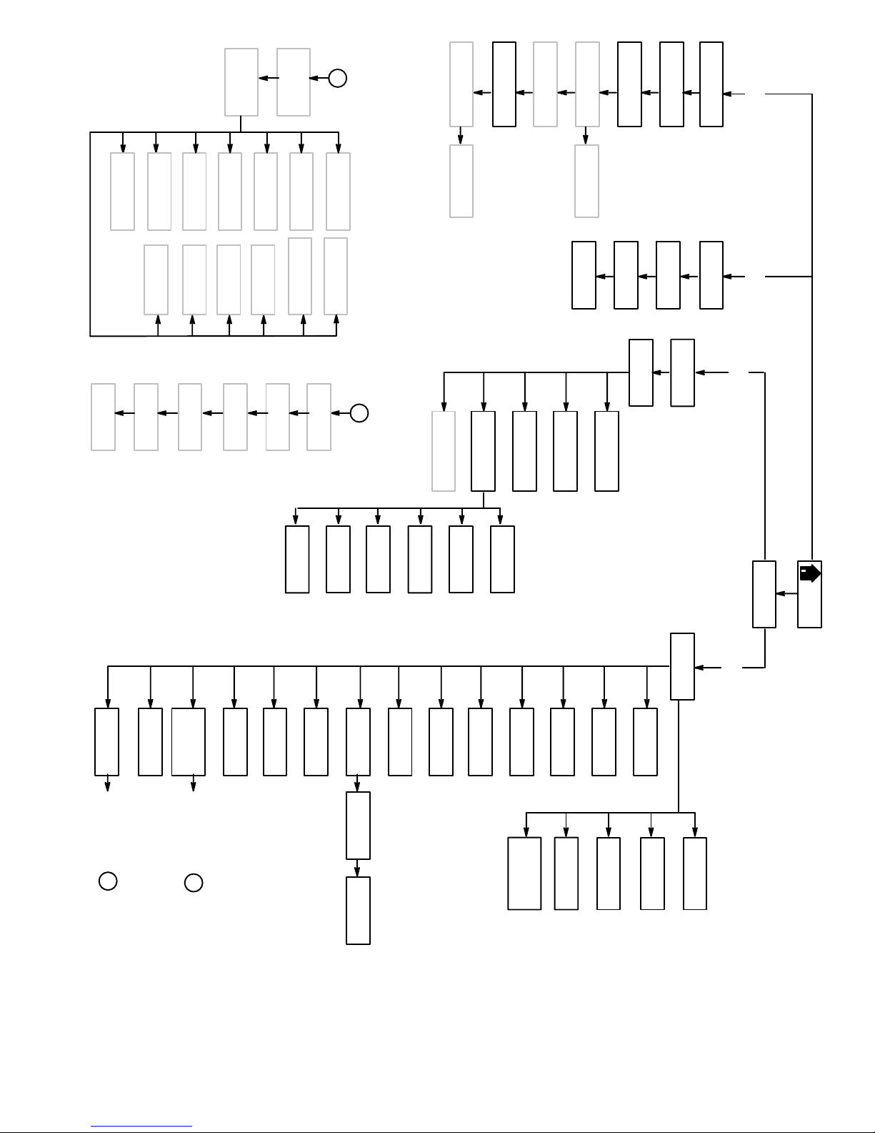
7
ICC7 C Solvent
(8–26)
(8–26)
6
ICC5 B Solvent
ICC6 C Dump
(8–25)
5
ICC102
(8–23)
Graph
4
ICC4 B Dump
(8–25)
quence
(8–22)
3
ICC3 A Solvent
(8–24)
(8–24)
ICC101 Se-
A
2
ICC1 Purge/Mix
ICC2 A Dump
(8–23)
Color Change
1
Integrated
RM7A Queue
(6–7)
RM7B Modify
(6–7)
RM6 Alarm
(6–6)
RM5 Recipe
(6–5)
RM4A Flowrate
(6–5)
RM4B Setpoint
(6–5)
RM3 Potlife
(6–4)
RM2 Flow
(6–4)
RM1 Target/Actual
(6–3)
1– Run Monitor 2–Totalizer
FC5 Meter
(8–20)
14
ICC13 Special
(8–28)
FC4 Delay
(8–19)
13
13
ICC12 Special
(8–28)
12
FC3 Output
(8–19)
12
ICC11 Special
(8–28)
(8–18)
11
(8–28)
11
FC2 Setpoint
ICC10 Special
ICC9 Gun 2
(8–27)
10
9
FC1 Source
(8–18)
6
S406 Gun 1
(9–15)
10
FCMenu
(8–17)
9
ICC8 Gun 1
(8–27)
8
5
S405 Mixed
(9–14)
B
(9–14)
8
Flow Control
4
S404 Solvent
(9–13)
7
5
S5 Flow Control
(9–16)
3
S403 “C”
6
S402 “B”
(9–13)
4
S4 Calibrate
(9–11)
2
(9–12)
5
3
(9–9)
1
S401 “A”
4
S3 Alarms
T4 Grand
(7–5)
2
S2 Sequence
(9–7)
3
1
S1 Ratio
(9–6)
2
T3 Batch
(7–4)
S102 Menu
(9–5)
1
(7–4)
T2 Job
S101 Select
(9–4)
CMenu
(8–4)
T1 Recipe
(7–3)
3–Recipe Setup
4–System Configuration
PASSWORD
(8–3)
(8–3)
HOME
C14 Color
(8–12)
Entry 2 or 3
A
C13 Int. Vol.
(8–12)
C12 Flow
Control
(8–11)
Entry 2 or 3
B
(8–11)
C11 Input
C10 Guns
(8–10)
Screen Map 5–3
C9 Mix Vol.
(NO TAG)
C8A Purge
(8–8)
C8B Purge
(8–9)
C8C Purge
(8–9)
(8–8)
C7 Solvent
(8–7)
C6 Flow Rate
C5 Potlife
(8–7)
C4 Recipe
(8–6)
C19 Air Flow
Switch
(8–15)
19
C3 Units
(8–6)
(8–14)
18
C18 Print
(8–5)
(8–14)
C2 Station
17
C17 Display
C1 Language
(8–5)
16
C16 Clock
(8–13)
15
C15 Password
(8–12)
Page 94

5–4 Screen Map
Page 95

6
Run Monitor
Run Monitor 6–1
Page 96

Run Monitor6–2
Page 97

Home Screen
Run Monitor
Screens Information
Graco PrecisionMix II 3K (R)
Version X.XX
HOME SCREEN Station: 1
1. RUN MONITOR
2. TOTALIZERS
3. RECIPE SETUP
4. SYSTEM CONFIGURATION
Select a menu item and press enter: > 1
Type in 1, then .
Press the next screen or previous screen
arrow key to move forward or backward
to the desired Run Monitor screen.
Press the HOME key to return to the
HOME screen.
RM1 Target/Actual
This is the HOME screen where you choose which
system function to enter.
RUN MONITOR (#1) has the normal operating
screens.
TOTALIZERS (#2) has the screens with information
on material usage on the selected recipe.
RECIPE SETUP (#3) screens allow you to setup
“recipes” (ratio programs) for a variety of fluids.
SYSTEM CONFIGURATION (#4) screens allow
you to setup the controller to operate according to
your system requirements.
Selecting #1 on the Home Screen will bring up the first
Run Monitor screen (RM1 – Target/Actual). The run
monitor screens allow you to monitor the status of the
system. The readings will be displayed in either cubic
centimeters (cc), liters (l), ounces (oz), and/or gallons
(gal), depending on how the system has been configured.
RUN MONITOR
00/00/00
MIX RATIO
(A:B, C:B)
COMPONENT
VOLUMES
JOB
TOTALS
Recipe: 1
Desired
AB 0.00:1
CB 0.00:1
Target
A 0.0
B 0.0
C 0.0
COMPONENT A =
COMPONENT B =
COMPONENT C =
SOLVENT =
Station: 1
00:00
Actual
0.00:1
0.00:1
Actual
0.0 cc
0.0 cc
0.0 cc
000000 cc
000000 cc
000000 cc
000000 cc
Mix Ratios
Desired Ratio is the ratio entered during recipe setup.
Actual Ratio is a ratio the system actually dispensed
on the last cycle.
Component Volumes
Target (left hand column) is the desired volumes of
Component A, Component B, and Component C that
the controller will request.
Actual (right hand column) shows the quantities of
Component A, Component B, and Component C as
they are being dispensed.
Component Volumes are always measured in
cubic centimeters.
Job Totals
Displays total volume for the current job of Component
A, Component B, Component C, and Solvent (if a solvent valve is installed and configured). The job totals
can be changed to read in ounces during system configuration. See page 8–6.
Run Monitor 6–3
Page 98

Screens Information
RM2 Flow Rate
*Run Monitor
RUN MONITOR
00/00/00
ACTUAL FLOW
COMPONENT A
COMPONENT B
COMPONENT C
Recipe: 1 Station: 1
00:00
FLOWRATE
= 000000 cc/min
= 000000 cc/min
= 000000 cc/min
= 000000 cc/min
RM3 Potlife Timer
RUN MONITOR Recipe: 1 Station: 1
00/00/00 00:00
Gun 1
Potlife Time Remaining: 000 min
Timer
System Idle Time Remaining: 00 min
Flow rate is a real time display of how much flow is
going through the system. It updates every two
seconds and is a weighted average of the previous
flow rate displays. The readings are taken by the
Component A, B, and C fluid meters. The flow rate
display can be altered in the setup program to read in
ounces per minute. See page 8–6.
Potlife Time Remaining
Potlife time remaining displays the time remaining
before a potlife alarm will occur. The timer does not
start until the controller detects mixed material is in the
lines.
System Idle Time Remaining
System Idle Time uses a 4 minute clock that counts
down the time that the spray device is not in use. After
4 minutes of not triggering the spray device, the mix
manifold closes and the screen changes to the System
Idle screen. When the spray device is triggered with
the operator switch set to mix, the PrecisionMix will
start again where it left off.
The potlife timer values will appear for the
quantity of gun(s) that were selected during
system configuration.
Run Monitor6–4
Page 99
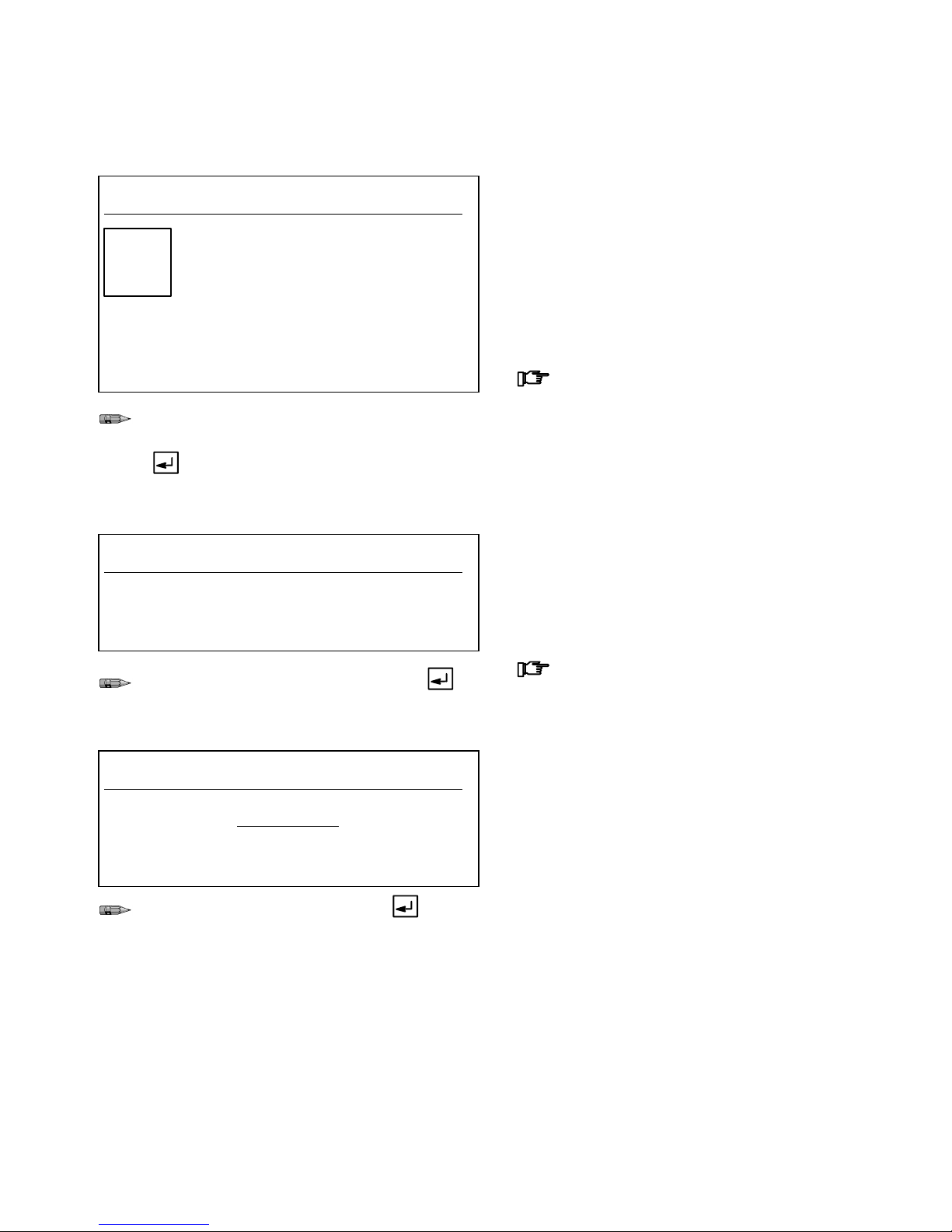
Screens Information
RM4A Flow Rate Setpoint
Run Monitor
RUN MONITOR Recipe: 1 Station: 1
00/00/00 00:00
Gun #1 Setpoint: 0000 cc/min
Flow Actual: 0000 cc/min
Rate Analog out: 00.0 mA
Setpoint in: 00.0 mA
Press Enter for a new Setpoint
If a new setpoint is desired and the user interface is the source of flow control data, press
to go to the next screen.
RM4B Enter New Setpoint
RUN MONITOR Recipe: 1 Station: 1
00/00/00 00:00
Enter new Setpoint for Gun 1:
> 0000 cc/min
Flow control can only be used with the proper hardware installation. The Flow Rate Setpoint screen only
appears if flow control is turned on. It shows the flow
control Setpoint and the Actual flow rate.
The mA reading for Analog out and Setpoint in is
converted to a pneumatic signal, which is applied to a
fluid pressure regulator to open the regulator a certain
amount.
The setpoint can be changed by the operator if
the user interface was set as the source of flow
control data during system configuration. See
page 8–18. If this option is not available,
Press Enter for a new Setpoint" will not
appear at the bottom of the screen.
The Enter New Setpoint screen only appears if the
user interface was set as the source of flow control
data during system configuration. See page 8–18. Use
this screen to enter the new Setpoint for the gun(s).
Type the new setpoint for the gun, then .
RM5 Recipe Select
RUN MONITOR Recipe: 1 Station: 1
00/00/00 00:00
RECIPE SELECT
New Recipe for Operation (1-63):
> 00
Type the new recipe number, then .
Setpoint changes made at this screen will not
be stored in the recipe data.
This screen only appears if the User Interface was
selected as the input for changing recipes. The recipe
screen will display the current recipe running.
Run Monitor 6–5
Page 100

Screens Information
RM6 Alarm History
Run Monitor
RUN MONITOR Recipe : 1 Station: 1
00/00/00 00:00
ALARM HISTORY
Description Value Time Date
1 A DOSE TIME 23:33 02/22
2 RATIO HIGH CB 00102 04:24 02/22
3 RATIO HIGH 00.97 04:24 02/22
4 C OVERDOSE 01449 03:28 02/22
5 A OVERDOSE 036.7 03:26 02/22
6 C OVERDOSE 05552 03:26 02/22
7 C OVERDOSE 02630 03:23 02/22
8 EXTERNAL 03:22 02/22
9 A OVERDOSE 037.3 03:22 02/22
10 C OVERDOSE 09917 03:22 02/22
The alarm history screen displays the last 10 alarms
that have occurred. See the alarm descriptions on
page 10–7. The most recent alarm will appear at the
top of the screen.
This screen does not ever completely clear. There is a
maximum of 10 alarm lines that can display. If there
are 10 lines and a new alarm occurs, alarm #10 will be
cleared and all alarms will shift down one location.
Run Monitor6–6
 Loading...