

Page 1
Instructions – Parts List
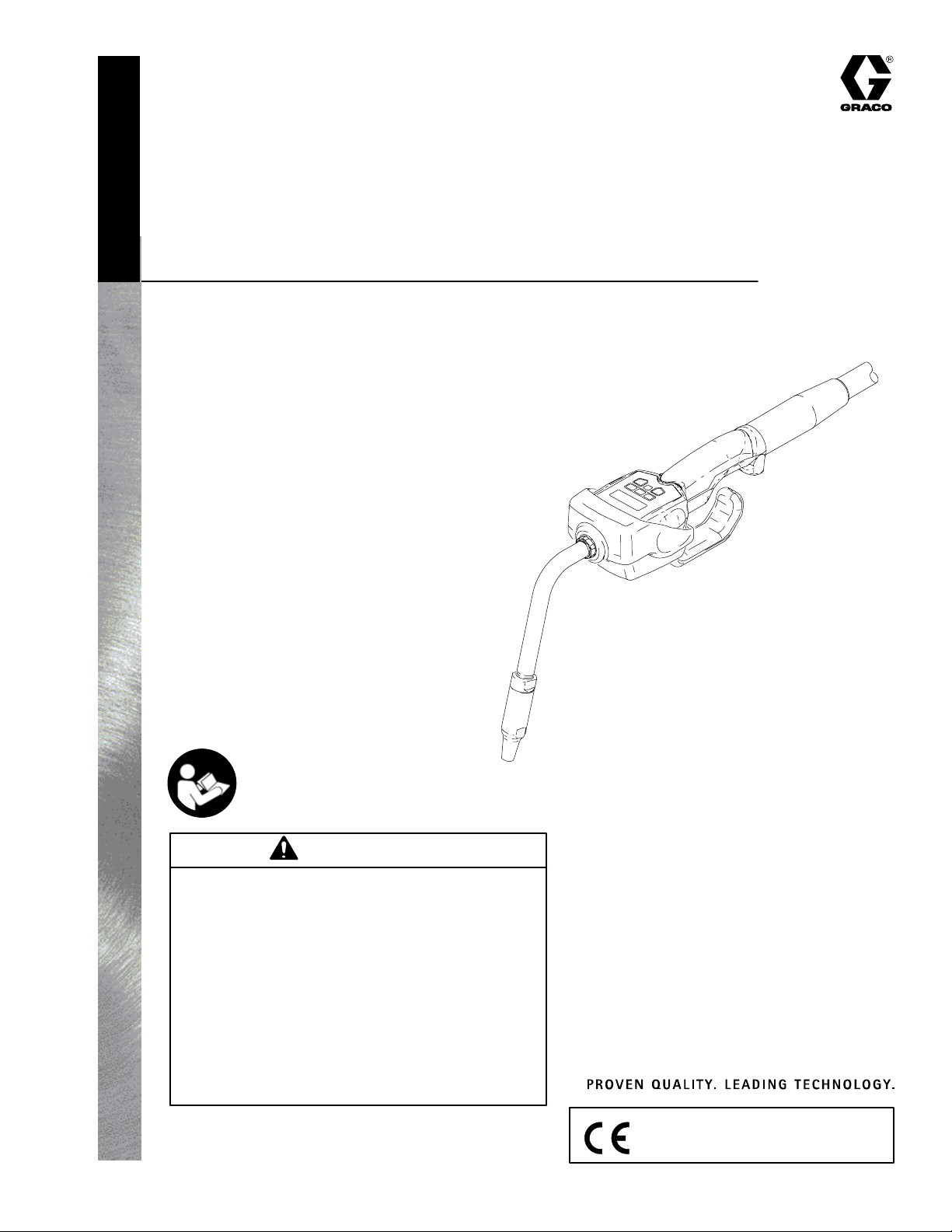
PRESET
PM5t Electronic
Metered Dispense Valves
For pre–set metered dispense of oils and antifreeze.
1000 psi (7 MPa, 69 bar) Maximum Working Pressure
5 gpm (18.9 lpm) Maximum Flow Rate
Model 238511 75_ bend 3/8–in. rigid tube
Model 238512 3/8–in. coupled flexible hose
Model 238515 90_ offset
Patent Nos.
4,883,199 DE3834454C2
D382,500 1025804
6,357,300 ZL97102971.7
6,047,906 187760
77664 13742
Model 238511 shown
309377E
TI0327
Important Safety instructions
Read all warnings and instructions in this manual.
Save these instructions.
CAUTION
D This dispense valve is designed to dispense
petroleum-based lubricants and antifreeze only.
Do not dispense windshield washer solvent with
this dispense valve.
D This dispense valve is designed for indoor use
only.
D This dispense valve is not designed for in-line
installation. Do not install with a shutoff valve on
the outlet side of the meter. Such installation
could result in damage to the meter housing
cover.
GRACO INC.ąP.O. BOX 1441ąMINNEAPOLIS, MNą55440-1441
Copyright 2001, Graco Inc. is registered to I.S. EN ISO 9001
Page 2
Table of Contents
Warnings 2. . . . . . . . . . . . . . . . . . . . . . . . . . . . . . . . . . . . . .
Installation 4. . . . . . . . . . . . . . . . . . . . . . . . . . . . . . . . . . . . .
Setup 7. . . . . . . . . . . . . . . . . . . . . . . . . . . . . . . . . . . . . . . . .
Operation 11. . . . . . . . . . . . . . . . . . . . . . . . . . . . . . . . . . . .
Troubleshooting 13. . . . . . . . . . . . . . . . . . . . . . . . . . . . . . .
Service 16. . . . . . . . . . . . . . . . . . . . . . . . . . . . . . . . . . . . . .
Parts List 18. . . . . . . . . . . . . . . . . . . . . . . . . . . . . . . . . . . . .
Parts Drawing 19. . . . . . . . . . . . . . . . . . . . . . . . . . . . . . . . .
Technical Data 20. . . . . . . . . . . . . . . . . . . . . . . . . . . . . . . .
Dimensional Drawing 21. . . . . . . . . . . . . . . . . . . . . . . . . .
Graco Standard Warranty 22. . . . . . . . . . . . . . . . . . . . . .
Graco Information 22. . . . . . . . . . . . . . . . . . . . . . . . . . . . .
WARNINGWARNING
EQUIPMENT MISUSE HAZARD
Equipment misuse can cause the equipment to rupture or malfunction and result in serious injury.
INSTRUCTIONS
D This equipment is for professional use only.
Symbols
Warning Symbol
WARNING
This symbol alerts you to the possibility of serious
injury or death if you do not follow the instructions.
Caution Symbol
CAUTION
This symbol alerts you to the possibility of damage to
or destruction of equipment if you do not follow the
instructions.
D Read all instruction manuals, tags, and labels before you operate this equipment.
D Use the equipment only for its intended purpose. If you are not sure, call your Graco distributor
for assistance.
D Do not alter or modify this equipment. Use only genuine Graco parts and accessories.
D Do not leave this dispense valve unattended while it is dispensing.
D Check equipment daily. Repair or replace worn or damaged parts immediately.
D Do not exceed the maximum working pressure of the lowest rated system component. See the
Technical Data on page 20 for the maximum working pressure of this component.
D Use fluids and solvents that are compatible with the equipment wetted parts. See the Technical
Data section of all equipment manuals. Read the fluid and solvent manufacturer’s warnings.
D Route hoses away from traffic areas, sharp edges, moving parts, and hot surfaces. Do not
expose Graco hoses to temperatures above 180_ F (82_ C) or below –40_ F (–40_ C).
D Comply with all applicable local, state, and national fire, electrical, and safety regulations.
D Do not point the dispense valve at anyone or at any part of the body.
D Do not put your hand or fingers over the end of the dispense valve.
D Do not stop or deflect leaks with your hand, body, glove, or rag.
D Use only extensions and nozzles that are designed for use with this dispense valve.
D Follow the Pressure Relief Procedure on page 5 before you clean, check, or service this
D Tighten all fluid connections before you operate this equipment.
D Check the hoses, tubes, and couplings daily. Replace worn or damaged parts immediately. Do
2 309377
equipment.
not repair high pressure couplings; you must replace the entire hose.
Page 3
WARNINGWARNING
FIRE AND EXPLOSION HAZARD
Improper grounding, poor ventilation, open flames, or sparks can cause a hazardous condition and
result in a fire or explosion and serious injury.
D Be sure the entire fluid system is properly grounded. Refer to your pump instruction manual for
complete details. See Grounding on page 6.
D If there is any static sparking or you feel an electric shock while using this equipment, stop
dispensing immediately. Do not use the equipment until you identify and correct the problem.
D Provide fresh air ventilation to avoid the buildup of flammable fumes from solvents or the fluid
being dispensed.
D Keep the dispensing area free of debris, including solvent, rags, and spilled gasoline.
D Do not smoke while flammable fluids or fumes are in the dispensing area.
3309377
Page 4
Installation
Typical Installations
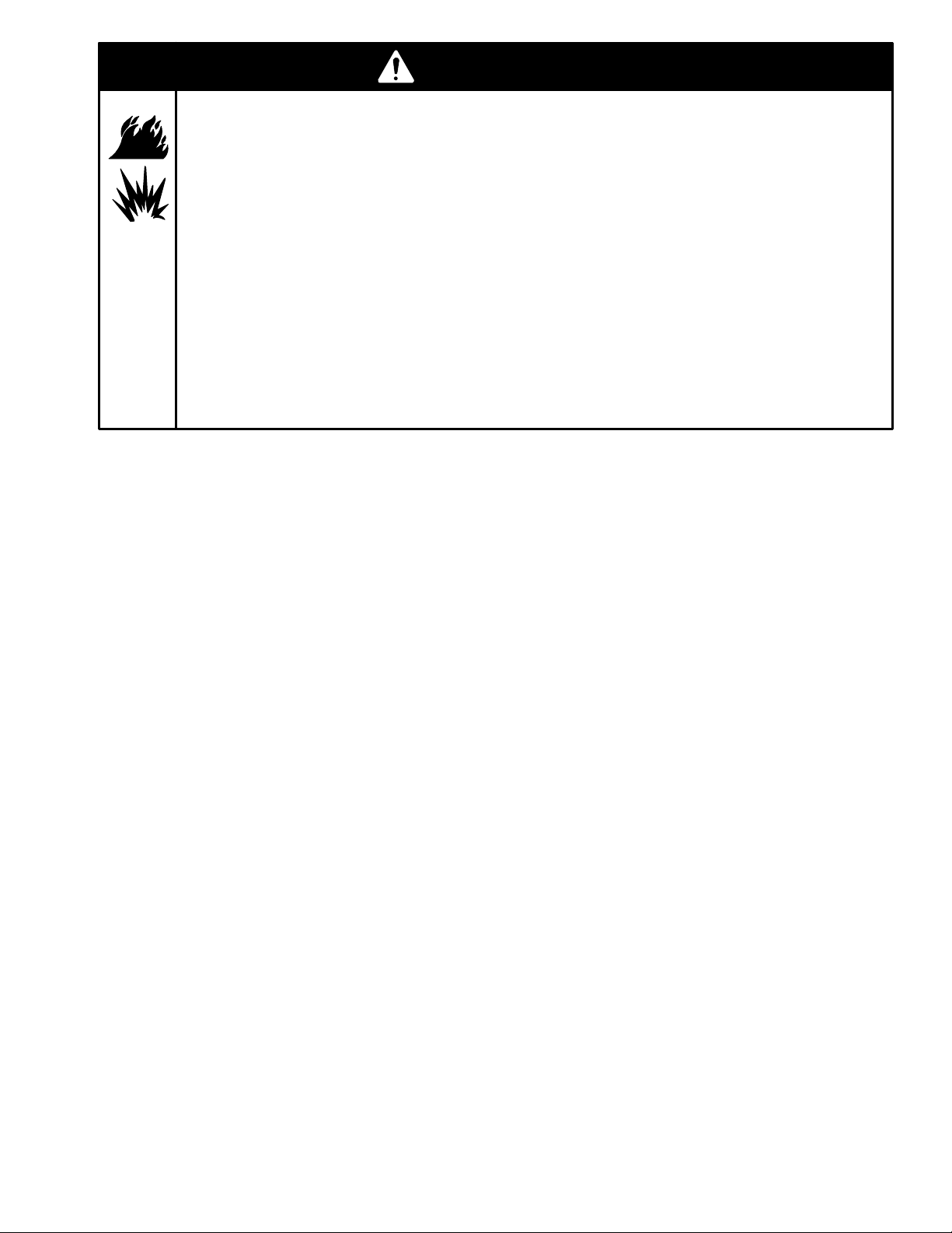
Fig. 1 shows a typical hose reel installation. These
dispense valves can also be installed on a console, as
shown in Fig. 2.
CAUTION
Do not use this dispense valve on non-Graco
consoles. Such use could result in the trigger
becoming inadvertently pressed while the dispense valve is stowed.
J
L
H
The typical installation shown in Fig. 1 is only a guide.
The components shown are typical; however, it is not a
complete system design. Contact your Graco distributor for assistance in designing a system to suit your
particular needs.
CAUTION
This dispense valve is not designed for in-line
installation. Do not install with a shut-off valve
on the outlet side of the meter. Such installation
could result in damage to the meter housing
cover.
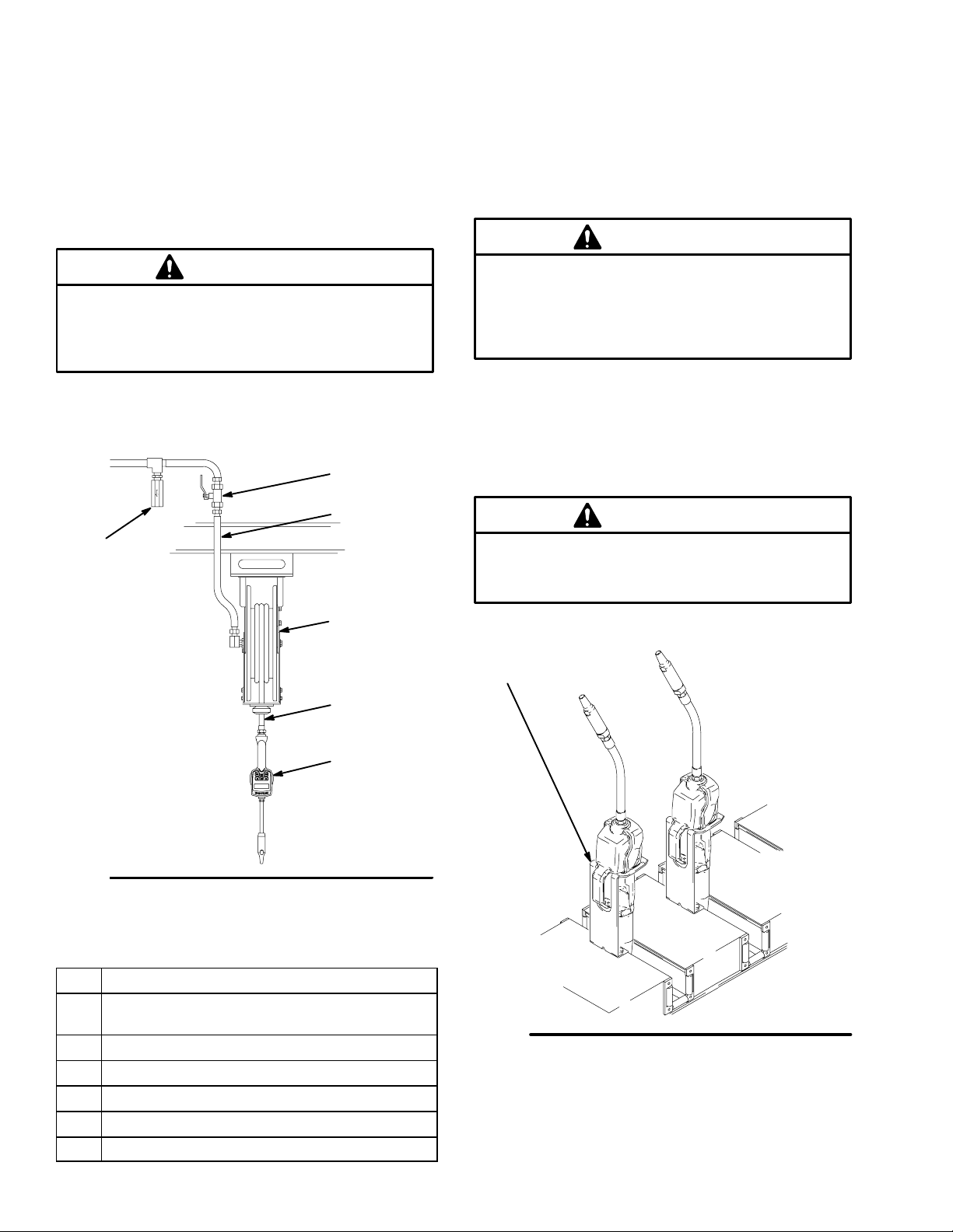
Mounting Bracket
Mounting bracket 196471 is available for resting a PM5
dispense valve on a console. See Fig. 2.
CAUTION
Do not obstruct the trigger of this dispense
valve, and do not set the unit down resting on its
trigger, or it might not stop dispensing.
M
K
N
Fig. 1
KEY DESCRIPTION
H Thermal relief kit (required) Part No. 235998
Install downstream from pump.
J Fluid shut-off valve
K Hose
L Hose reel fluid inlet hose
M Hose reel
N PM5 electronic metered dispense valve
4 309377
06174B
mounting bracket
196471
Fig. 2
TI0334
Page 5
Installation
WARNING
PRESSURIZED EQUIPMENT HAZARD
The equipment stays pressurized until pressure is
manually relieved. To reduce the risk of serious
injury from pressurized fluid, accidental spray from
the dispense valve, or splashing fluid, follow the
Pressure Relief Procedure when you
D Are instructed to relieve pressure
D Check, clean, or service any system equipment
D Install or clean fluid nozzles or filter
Pressure Relief Procedure
1. Turn off the power supply to the pump.
2. Trigger the dispense valve into a waste container
to relieve pressure.
3. Open any bleed-type master air valves and fluid
drain valves in the system.
4. Leave the drain valve open until you are ready to
pressurize the system.
WARNING
FIRE AND EXPLOSION HAZARD
The movement of fluids through the
dispensing system generates static
electricity. The static electricity can
cause volatile fumes to ignite, resulting in explosion
and fire. The dispensing system must grounded.
See Grounding on page 6.
Installation Procedure
CAUTION
If this is a new installation, or if the fluid in the
lines is contaminated, flush the lines before you
install the metered valve. Contaminated lines
could cause the valve to leak.
1. If this is an existing installation, go to step 7.
Steps 2 through 6 are the Flushing Procedure.
2. Close the fluid shut-off valve (J) at each dispense
position.
3. Make sure the main fluid outlet valve at the pump
is closed, the air pressure to the pump motor is
adjusted, and the air valve is open. Slowly open
the main fluid valve.
4. Place the hose end (with no dispense valve connected) into a container for waste oil. Secure the
hose in the container so it will not come out during
flushing. If you have multiple dispense positions,
first flush the dispense position farthest from the
pump, and work your way toward the pump.
5. Slowly open the shut-off valve (J) at the dispense
position. Flush out a sufficient amount of oil to
ensure that the entire system is clean, and close
the valve.
6. Repeat step 5 at all other dispense positions.
7. Relieve the pressure.
Pre-Installation Procedure
1. Relieve the pressure.
WARNING
To reduce the risk of serious injury whenever you
are instructed to relieve pressure, always follow the
Pressure Relief Procedure above.
2. Close the shut-off valve (item J in Fig. 1).
3. Ground the hose and reel or console. See
Grounding on page 6. Leave a minimum two
engaged threads bare when using PTFE tape. The
bare threads ensure a ground is maintained.
WARNING
To reduce the risk of serious injury, whenever you
are instructed to relieve pressure, always follow the
Pressure Relief Procedure at left.
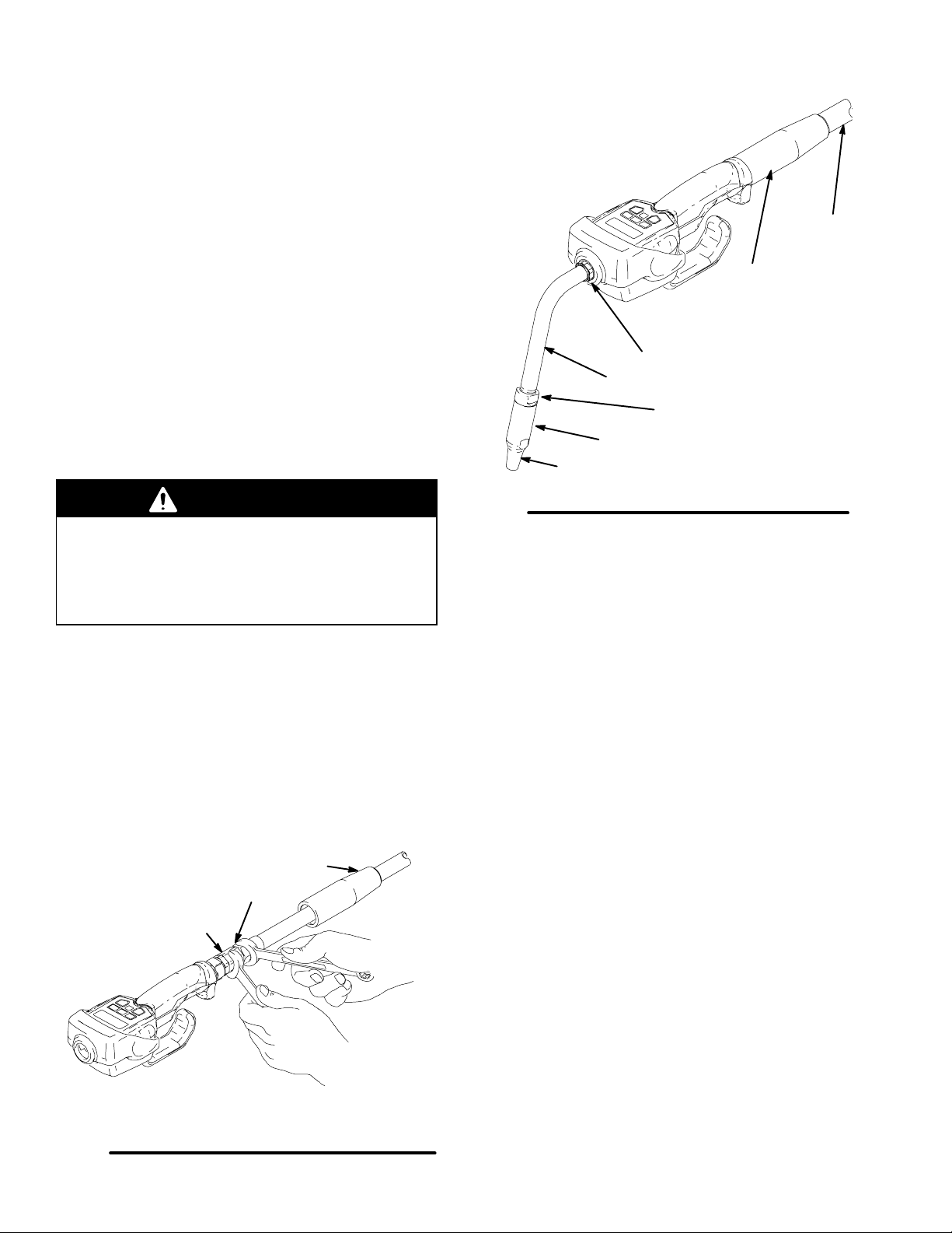
8. Slide the swivel cover (4) of the PM5 onto the
hose, small end first. See Fig. 3.
9. Apply thread sealant to the male threads of the
hose fitting, thread the hose fitting into the swivel
(3) of the PM5, and tighten it firmly. See Fig. 3.
NOTE: Make sure you let the sealant cure to the
manufacturer’s recommendations before you let
fluid into the system.
5309377
Page 6
Installation
10. Thread the sealing nut (5c, 6c, or 7c) onto the
extension (5a) or street elbow (6d or 7d), thread
the extension or elbow in at least three full turns,
position it for proper alignment, and tighten the
sealing nut. The PTFE seal on the sealing nut
must face the valve housing. See Fig. 4.
NOTE: The flexible extension (6a) can also be
threaded directly into the meter outlet without the
street elbow or sealing nut. See the note in the
Parts Drawing on page 19.
11. Thread the new nozzle (5b, 6b, or 7b) onto the
extension, and, with an open-end adjustable
wrench, tighten it firmly. See Fig. 4.
NOTE: Only tighten the nozzle with the wrench
on the flats of the nozzle bushing. Do not disas-
semble the bushing from the nozzle. Disassembly will affect the performance of the nozzle.
WARNING
Model shown has
75_ bend rigid
extension
5b
Fig. 4
hose
4
5c
5a
nozzle bushing
Nozzle is not serviceable.
TI0327
Do not use Graco’s old nozzle (Part No. 203655) or
any other manual shut-off nozzle on the PM5
extension. You must use the new automatic nozzle
that is provided with the PM5, or the meter could
be damaged. Do not use any sealant material.
12. Open all dispense position shut-off valves, and
start the pump to pressurize the system. See the
Operation section for proper operation of meter.
13. To ensure dispensing accuracy, purge all air from
the fluid lines and dispense valve before you use
it. Set the system flow to the desired flow rate,
which is typically 1.5 gpm. Do not exceed a 5-gpm
flow rate.
Slide onto
hose before
connecting.
hose fitting
3
4
Grounding
Proper grounding is an essential part of maintaining a
safe system.
To reduce the risk of static sparking, ground all system
components according to local and national electrical
codes. Refer to the user manuals for the pump and
other system components, and ground the following:
D Pump: Follow the manufacturer’s recommend-
ations.
D Air and Fluid hoses: Use only grounded hoses.
D Air compressor: Follow the manufacturer’s recom-
mendations.
Fig. 3
6 309377
TI0328
D Fluid supply container: Follow the local code.
To maintain grounding continuity when flushing or
relieving pressure, always hold a metal part of the
valve firmly to the side of a grounded metal pail, then
trigger the valve.
Page 7
Setup
Terms
The following terms are shown on the display and/or
used often in this instruction manual.
D R–TOTAL: resettable total
Displayed to show the cumulative amount that the
dispense valve has dispensed in all modes. It can
be reset to zero.
D TOTAL: non-resettable total
Displayed to show the cumulative amount that the
dispense valve has dispensed in all modes for the
history of the unit. It cannot be reset.
D MANUAL mode
Dispense mode in which the display counts up from
zero to show the dispensed amount. In this mode,
you may lock the trigger, but you must manually
unlock it when the desired amount is dispensed.
Memory setting also unlocks the trigger.
D AUTO mode
Dispense mode in which a preset, user-entered
amount is dispensed. When the preset amount is
dispensed, a beep sounds, the trigger unlocks to
stop the unit from dispensing, and the amount
dispensed is displayed. At this point, you may
dispense more by pulling back the trigger, and the
display resumes counting up in Manual mode.
D Asleep / Awake
Asleep is a battery-saving mode in which the display goes blank after 45 seconds of inactivity during
normal operation and 2 minutes when in the options
menu. The display comes awake from sleep mode
when you press the Manual/Reset or Auto/Reset
button, but not when you squeeze the trigger to
dispense fluid. The unit does keep track of the
amount dispensed while the display is asleep.
NOTE: If the unit falls asleep after any dispense
cycle, and you do wake it up by pressing the Auto/
Reset button, the previously dispensed amount is
cleared, and the Auto mode dispense amount
stored in memory is displayed. You will be at the
beginning of an Auto mode dispense cycle.
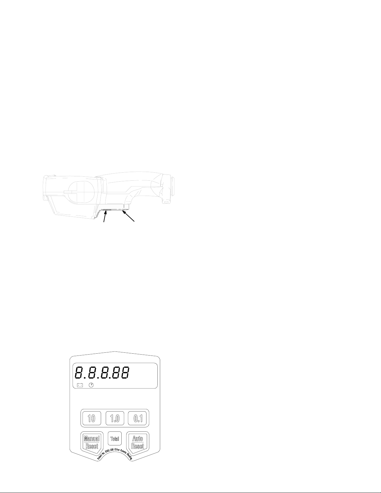
Keypad Buttons
The buttons on the keypad and their functions are as
follows (see the figure below):
D 10, 1.0, and 0.1
Used in Auto mode and during setup to enter
dispense amounts.
D MANUAL / RESET and AUTO / RESET
Used individually to select Manual mode and Auto
mode. Used together (pressed simultaneously) to
access the setup menus.
For both of these buttons, the first push selects the
mode, and the second push resets the display to
zero.
D TOTAL
Used in any mode to see the resettable total and
the non-resettable total.
NOTE: All buttons are disabled while fluid is being
dispensed.
GAL
AUTO
If the unit falls asleep after any dispense cycle, and
you do not wake it up by pressing the Manual/Reset or Auto/Reset button, it will default to manual
mode. When dispensing begins you will be at the
beginning of a manual mode dispense cycle.
06044A
7309377
Page 8

Setup
Selecting Dispensing Options
This is the procedure for setting or changing the resettable total, units of measurement, calibration factor, auto
preset amount, and shut-off default amount:
1. If the display is asleep, wake it up by pressing the Manual/Reset or Auto/Reset button.
2. To enter the dispensing options menus from any mode, press and hold the Manual/Reset and Auto/Reset
buttons simultaneously for four seconds.
The first menu is the Resettable Total menu, which is described in the first subsection below. You can advance
through the menus by pressing the Auto/Reset button. You will know which menu you are in, because a menu
indicator will be blinking in the display. The value that is displayed when you leave each menu and advance to
the next is the value that gets stored.
Resettable Total
In this menu, you can reset the resettable total to zero
or leave it unchanged. The resettable total accumulates until the next time it is manually reset.
1. If you have not already entered the dispensing
options menus, do steps 1 and 2 in Selecting
Dispensing Options above.
2. With R–TOTAL blinking and the current resettable
total displayed, as shown below, do ONE of the
following two options:
D Press the Manual/Reset button.
The resettable total is set to zero, and 0 GAL or 0
LITERS is displayed.
You can press the Manual/Reset button again to toggle
between zero and the previously displayed resettable
total. To lock in the displayed value and advance to
the Units of Measurement menu, press the Auto/Reset
button.
OR
D Press the Auto/Reset button.
The currently displayed value is stored, and the display
advances to the Units of Measurement menu.
Units of Measurement
In this menu, you can set the units of measurement to
quarts, gallons, pints, or liters.
1. If you have not already entered the dispensing
options menus, do steps 1 and 2 in Selecting
Dispensing Options above.
2. Press the Auto/Reset button repeatedly until QTS,
GAL, LITERS, or PTS blinks to indicate that you
are in the Units-of Measurement menu.
3. With QTS, GAL, LITERS, or PTS blinking, as
shown below, do ONE of the following two options:
D Press the Manual/Reset button.
Each time you press the Manual/Reset button, the
display scrolls to the next unit of measurement. To
lock in the new unit of measurement and advance to
the Calibration Factor menu, press the Auto/Reset
button.
OR
D Press the Auto/Reset button.
The displayed unit of measurement is retained, and
the display advances to the Calibration Factor menu.
D Do not obstruct the trigger
D Do not leave unattended
8 309377
GAL
R-TOTAL
! CAUTION
To prevent overfills and spills
D Do not operate below 32_ F (0_ C)
Maximum Working Pressure 7 MPa (70 bar, 1000 PSI)
D Read instruction manual
06044A
! CAUTION
D Do not obstruct the trigger
D Do not leave unattended
To prevent overfills and spills
D Do not operate below 32_ F (0_ C)
Maximum Working Pressure 7 MPa (70 bar, 1000 PSI)
D Read instruction manual
GAL
06044A
Page 9
Setup
Calibration Factor
In this menu, you can recalibrate the meter for different
fluids.
1. If you have not already entered the dispensing
options menus, do steps 1 and 2 in Selecting
Dispensing Options on page 8.
2. Press the Auto/Reset button repeatedly until CAL
blinks and the current calibration factor is displayed to indicate that you are in the Calibration
menu.
3. With CAL blinking, you can press the Auto/Reset
button and choose not to change the calibration
factor, which advances to the Auto Preset Amount
menu.
OR
You can recalibrate the meter as follows:
3a. If the unit of measurement is liters, dispense
exactly one liter of fluid into a calibrated
1-liter container. If the unit of measurement
is gallons, pints, or quarts, dispense exactly
one quart of fluid into a calibrated 1-quart
container. For proper calibration, you must
dispense the exact amount, according to the
markings on the container.
After dispensing, the displayed number is the
new calibration factor. The new calibration
factor must be within 20 percent of the factory default value [in the range of 294–442
quarts (310–467 liters)], or it will not be
accepted.
The following table lists approximate calibration factors for different fluids. Your calibration number may vary slightly due to temperature or flow rate.
Calibration Number
Fluid
Quarts Liters
Auto Preset Amount
In this menu, you can specify an amount to be displayed when you enter the Auto dispense mode.
Typically, you would enter the amount you most frequently dispense.
1. If you have not already entered the dispensing
options menus, do steps 1 and 2 in Selecting
Dispensing Options on page 8.
2. Press the Auto/Reset button repeatedly until
AUTO blinks and the auto preset amount in
memory is displayed to indicate that you are in the
Auto Preset Amount menu. This is the amount
that is displayed when the Auto/Reset button is
pressed during normal operation.
3. With AUTO blinking and the stored auto preset
amount displayed, as shown below, do ONE of the
following two options:
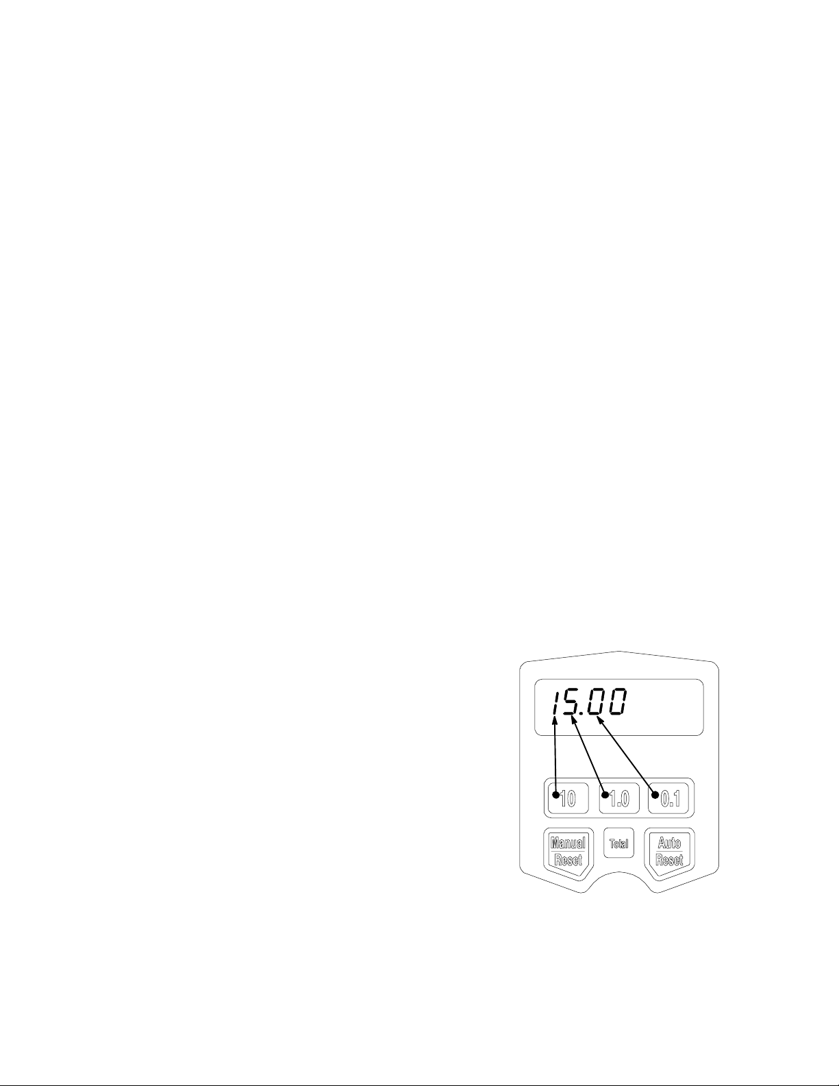
D Enter a new auto preset amount by pressing
the 10 button to change the 10s digit,
the 1.0 button to change the 1s digit, and
the 0.1 button the change the first decimal
digit.
In the figure below, the arrows point from the numbered buttons on the keypad to the corresponding
digits in the display.
NOTE: If you press and hold the 10, 1.0, or 0.1 buttons, the digits advance rapidly.
To store the displayed auto preset amount in memory
and advance to the Shut-Off Default Amount menu,
press the Auto/Reset button.
OR
D Press the Auto/Reset button.
The currently displayed auto preset amount is
retained, and the display advances to the Shut-Off
Default Amount menu.
oil (10W–30) 368 389
gear lube 368 389
automatic
368 389
transmission
fluid
antifreeze 347 367
Calibration factors at 70_ F (21_ C) at 2.0 gpm (7.6 lpm).
3b. Press the Auto/Reset button to store the new
calibration factor and advance to the Auto
Preset Amount menu.
AUTO
! CAUTION
D Do not obstruct the trigger
D Do not leave unattended
To prevent overfills and spills
D Do not operate below 32_ F (0_ C)
Maximum Working Pressure 7 MPa (70 bar, 1000 PSI)
D Read instruction manual
GAL
06044A
9309377
Page 10

Shut-Off Default Amount
Setup
The shut-off default amount is for preventing accidental overfills when dispensing with the trigger locked in
Manual mode. The shut-off default amount is factory
preset at 5 quarts.
In this menu, you can change the shut-off default
amount.
1. If you have not already entered the dispensing
options menus, do steps 1 and 2 in Selecting
Dispensing Options on page 8.
2. Press the Auto/Reset button repeatedly until the
clock icon blinks, and the stored shut-off default
amount is displayed to indicate that you are in the
Shut-off Default Amount menu.
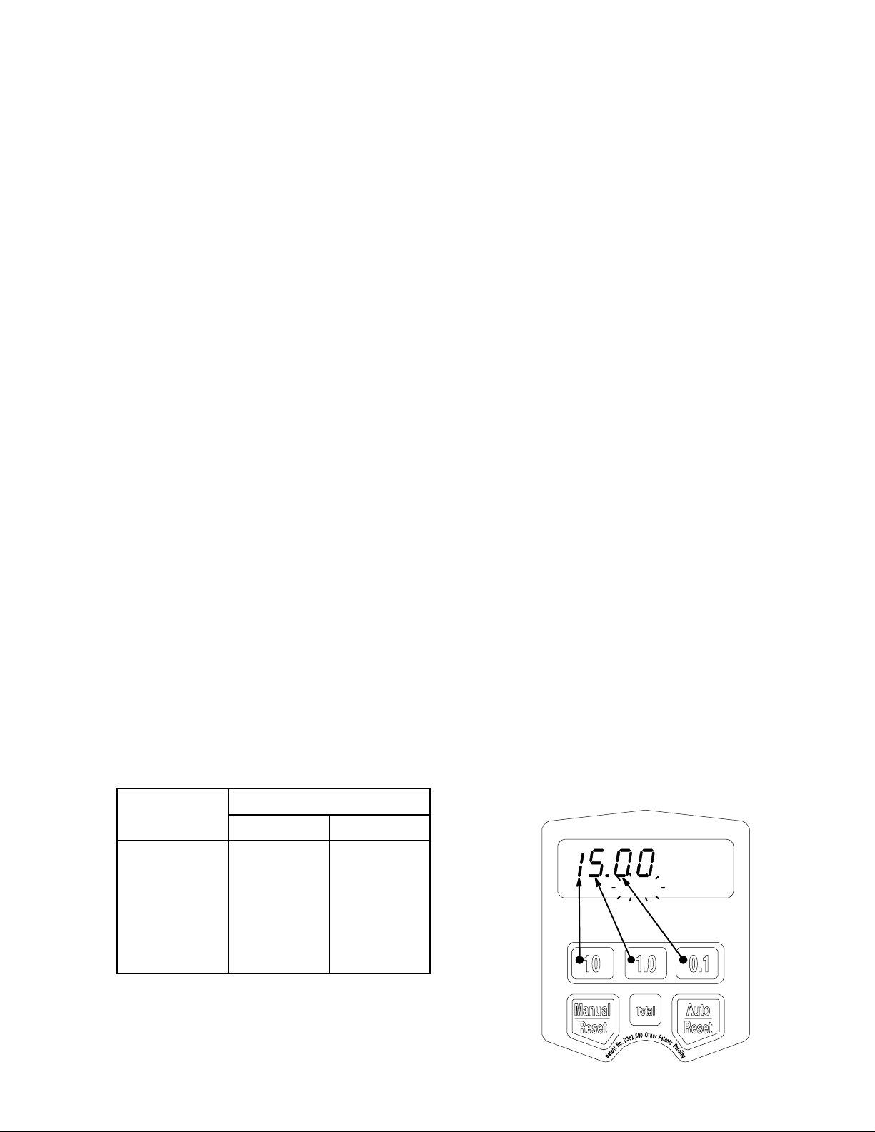
3. With the clock icon blinking and the stored shut-off
default amount displayed, as shown below, do
ONE of the following two options:
D Enter a new shut-off default amount by press-
ing the 10 button to change the 10s digit,
the 1.0 button to change the 1s digit, and
the 0.1 button the change the first decimal
digit. You cannot enter zero. To lock in the
new shut-off default amount and exit the
dispensing options menus, press the Auto/Reset button.
The PM5 beeps and returns to the Manual dispense
mode to indicate that you have exited the dispensing
options menus.
OR
D Press the Auto/Reset button.
The PM5 beeps and returns to the Manual dispense
mode to indicate that you have exited the dispensing
options menus.
QTS
! CAUTION
D Do not obstruct the trigger
D Do not leave unattended
To prevent overfills and spills
D Do not operate below 32_ F (0_ C)
Maximum Working Pressure 7 MPa (70 bar, 1000 PSI)
D Read instruction manual
06044A
10 309377
Page 11
Operation
Locking and Unlocking the Trigger
The trigger on this dispense valve has a locking mechanism. In Auto mode, the unit stops dispensing when
the entered amount has been dispensed. In Manual
mode, the trigger does not automatically unlock; you
must unlock it manually.
To lock the trigger, press on the part of the trigger
that has the textured grip (see below) until you feel it
click into the locked position.
To unlock the trigger, press on the smooth part of
the trigger (see below) until you feel it click out of the
locked position. When you release the trigger, fluid
flow stops.
Press here
to lock.
Press here
to unlock.
06227A
Dispensing Fluid in Manual Mode
1. Press the Manual/Reset button.
If the display was asleep, it wakes up and displays
the amount that was displayed before it fell asleep.
If the display was awake, and the meter is in the
Manual dispense mode, the meter beeps, and the
display clears to 0.00.
If the display was awake, and the unit is in the Viewing Totals mode or the Auto dispense mode, the meter
switches to the Manual dispense mode.
2. When the display is awake, you can dispense from
zero or from the displayed amount by doing one of
the following:
D Press the Manual/Reset button again to clear
the display to 0.00 if it is not already at 0.00.
Then go to step 3.
Checking Segments in the Display
When you press the Manual/Reset button or the
Auto/Reset button when the display is awake and in
the Manual or Auto dispense mode, the Segment
Check is displayed briefly. This display allows you to
check for burned out segments in the display. Press
the Manual/Reset or Auto/Reset button repeatedly to
get a good look at each segment in the display. The
Segment Check should show all of the segments
shown below.
QTS
PTS
CAL
GAL
LITERS
R-TOTAL
,, ,
AUTO
! CAUTION
D Do not obstruct the trigger
D Do not leave unattended
To prevent overfills and spills
D Do not operate below 32_ F (0_ C)
Maximum Working Pressure 7 MPa (70 bar, 1000 PSI)
D Read instruction manual
OR
D Go straight to step 3 to dispense from the
displayed amount.
3. Squeeze the trigger. You may lock it. See Lock-
ing and Unlocking the Trigger at left.
Fluid flows, and the amount displayed counts up from
zero or the previously dispensed amount.
4. Release/unlock the trigger when you have dispensed the desired amount of fluid.
Fluid flow stops, and the amount you have dispensed
is displayed.
You may press the Manual/Reset button again to reset
the displayed amount to zero.
06044A
NOTE: When the trigger is released, the automatic
nozzle prevents the fluid in the extension from running
out.
11309377
Page 12

Operation
Dispensing Fluid in Auto Mode
CAUTION
Before you begin a preset dispense cycle, make
sure AUTO is displayed. If you do not see
AUTO on the display, you are not in the Auto
dispense mode, and fluid flow will not stop when
the auto preset amount is dispensed.
1. Press the Auto/Reset button.
The display wakes up if it was asleep, and AUTO and
the stored preset dispense amount are displayed. The
factory default is 0.00.
NOTE: To change the stored preset dispense
amount, see Auto Preset Amount on page 9.
2. You can dispense or change the displayed preset
amount by doing one of the following:
D Go straight to step 3 to dispense the displayed
preset amount.
Viewing Totals
This is the procedure for viewing the non-resettable
and resettable totals. To change the resettable total,
see Resettable Total on page 8.
1. If the display is blank, press the Manual/Reset or
Auto/Reset button to wake it up.
2. Press the Total button to view the non-resettable
total amount.
If the unit of measurement is gallons, quarts, or pints,
the total is displayed in gallons, as shown below. If the
unit of measurement is liters, the total is displayed in
liters.
GAL
TOTAL
! CAUTION
D Do not obstruct the trigger
D Do not leave unattended
To prevent overfills and spills
D Do not operate below 32_ F (0_ C)
Maximum Working Pressure 7 MPa (70 bar, 1000 PSI)
D Read instruction manual
OR
D To change the displayed preset amount, you
can set the display to zero by pressing the
Auto/Reset button, then press the10 button to
change the 10s digit, press the 1.0 button to
change the 1s digit, and press the 0.1 button
the change the first decimal digit. Then go to
step 3.
3. Lock the trigger. See Locking and Unlocking
the Trigger on page 11.
Fluid flows, and the displayed dispensed amount
counts up from zero. When the preset amount is
dispensed, the unit beeps, the trigger unlocks, fluid
flow stops, the dispensed amount is displayed, and
the meter switches to the Manual dispense mode.
If you want to stop fluid flow before the preset amount
is dispensed, manually unlock the trigger. To continue
the dispense, lock the trigger, and the dispensed
amount resumes counting toward the preset amount.
If you want to continue dispensing after the trigger
unlocks at the preset dispense amount, squeeze the
trigger, and the dispensed amount resumes counting in
the Manual dispense mode until you release the trigger.
NOTE: When the trigger unlocks, the automatic
nozzle prevents the fluid in the extension from running
out.
12 309377
06044A
3. Press the Total button again to view the resettable
total amount.
If the unit of measurement is gallons, quarts, or pints,
the resettable total is displayed in gallons, as shown
below. If the unit of measurement is liters, the resettable total is displayed in liters.
GAL
R-TOTAL
! CAUTION
D Do not obstruct the trigger
D Do not leave unattended
To prevent overfills and spills
D Do not operate below 32_ F (0_ C)
Maximum Working Pressure 7 MPa (70 bar, 1000 PSI)
D Read instruction manual
06044A
Pressing the Total button repeatedly toggles between
the non-resettable and resettable total.
4. Press the Manual/Reset or Auto/Reset button to
return to the Manual or Auto dispensing mode.
Page 13

Troubleshooting
Relieve the pressure before you check or repair the
meter. Be sure all other valves and controls and the
pump are operating properly.
To reduce the risk of serious injury whenever you
are instructed to relieve pressure, always follow the
Pressure Relief Procedure on page 5.
Problem Cause Solution
Battery icon is displayed. Battery is low. Replace the battery. See Replacing
WARNING
the Battery on page 16.
Battery icon is blinking, and
bAtt is blinking.
Display does not activate. Battery is defective or dead.
Slow or no fluid flow Filter is clogged.
Battery is dead. Replace the battery. See Replacing
Electronic control is malfunctioning.
A dispense mode has not been
selected.
Pump pressure is low.
Shut-off valve is not fully open.
Foreign material is jammed in the
meter housing.
the Battery on page 16.
Replace the battery. See Replacing
the Battery on page 16.
Replace the electronic control
(clamshell).
Select a dispense mode by pressing
the Manual/Reset button or the
Auto/Reset button.
1. Relieve the pressure.
2. Clean or replace the filter. See
Replacing the Filter on page 16.
3. If the problem remains, contact
your Graco distributor for repair
or replacement.
Turn up pump pressure.
Fully open shut-off valve.
Contact your Graco distributor for
repair or replacement.
Displayed dispensed amount
is not accurate.
Unit needs to be calibrated for the
fluid that is being dispensed.
Calibrate the meter for the fluid that is
being dispensed. See Calibration
Factor on page 9.
continued
13309377
Page 14

Problem Cause Solution
Meter leaks from:
Troubleshooting
Cover/Control Poor swivel (3)/hose connection.
Meter leaks from:
Automatic
nozzle
NOTE: It is important to distinguish between the two
causes of this problem. A
new nozzle will not correct a
fluid leak caused by a faulty
valve.
Poor swivel (3)/meter housing
connection.
Damaged valve stem (16) assembly.
Poor seal at meter housing plate.
NOTE: Place a straight edge along
meter housing plate. If flat, plate and
seal are ok. If plate is not flat, meter
is damaged.
Automatic nozzle (5b, 6b, or 7b) has
a damaged seal.
Valve (16) has damaged or
obstructed seals.
Apply PTFE tape (leave minimum 2
engaged threads uncovered for
electrical continuity) or sealant to
threads of hose and tighten the
connection. See step 9 in
Installation Procedure.
Torque the fitting to 20–25 ft.lb.
Replace or clean valve stem and
O–rings. See Servicing the Valve.
Contact your Graco distributor for
repairs or replacement.
Replace the nozzle. See Replacing
the Automatic Nozzle on page 17.
Replace or clean valve stem and
o-rings. See Servicing the Valve on
page 17.
Meter leaks from:
Swivel
Unit does not stop dispensing
when assumed auto amount
is dispensed.
Poor swivel (3)/hose connection
Poor swivel (3)/meter housing
connection.
Auto amount was not entered.
Trigger is obstructed, or unit has
been set down resting on its trigger.
Apply PTFE tape (leave minimum 2
engaged threads uncovered for electrical continuity) or sealant to threads
of hose and tighten the connection.
See step 9 in Installation Proce-
dure.
Torque the fitting to 20–25 ft.lb.
Enter a preset dispense amount in
the Auto dispense mode. AUTO
must be displayed below the amount.
Never set the unit down resting on its
trigger.
14 309377
Page 15

Troubleshooting
Error Codes
Error codes are listed below. Even in an error condition, the unit keeps track of the amount dispensed.
With any error code displayed, as shown at right, you
can
D Press the Manual/Reset button.
Error code is cleared, unit switches into Manual
mode, and dispensed amount is displayed.
D Press the Auto/Reset button.
Error code is cleared, unit switches into Auto mode,
and the preset amount is displayed.
Error Code Cause Solution
! CAUTION
D Do not obstruct the trigger
D Do not leave unattended
To prevent overfills and spills
D Do not operate below 32_ F (0_ C)
Maximum Working Pressure 7 MPa (70 bar, 1000 PSI)
D Read instruction manual
06044A
Err 1 Flow rate is higher than 5 gpm.
or
Air was pumped through the line.
Err 2 Switch Error: Error occurred with
pick-up in internal gear.
or
Unit was dropped or unit encountered excessive vibration during
shipping.
Err 4 Flow has continued after it should
have shut off.
Err 5 The unit has dispensed the shut-off
default amount and has stopped
fluid flow.
Err 6 A preset dispense amount of zero
was entered for the dispense or is
stored as the default, and a Preset
dispense was attempted.
Adjust the flow rate so it is not higher
than 5 gpm.
Purge air from the line.
Ensure that your flow rate is not
higher than 5 gpm. For further assistance, contact your Graco distributor.
Press the Manual/Reset button at
start-up.
Check if the unit is resting on the
trigger or if an obstruction is pressing
the trigger. The unit checks for flow
every two seconds, and it beeps and
repeats the error code until the
trigger is released and the error code
cleared.
Press the Manual/Reset button, and
dispense again. To change the
shut-off default amount, see the
Shut-off Default Amount section
on page 10.
Enter an amount that is not zero.
See the Auto Preset Amount
section on page 9.
15309377
Page 16
Service
Replacing the Battery
WARNING
FIRE AND EXPLOSION HAZARD
Only replace the battery in a
non-hazardous location, away from
flammable fluids or fumes.
You may order battery Part No. 113716 separately.
Battery required to meet safety approvals:
Duracell alkaline MN1604, PC1604
or
Eveready alkaline EN22, 522
CAUTION
Before you replace the battery, press the Manual/
Reset button, which clears the dispensed amount
to zero. This saves everything to memory.
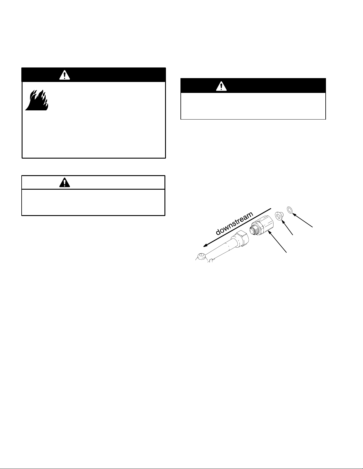
Replacing the Filter
The filter (25) is replaceable. To replace the filter, do
the following:
1. Relieve the pressure.
WARNING
To reduce the risk of serious injury whenever you
are instructed to relieve pressure, always follow the
Pressure Relief Procedure on page 5.
2. Unscrew the hose from the swivel (3).
3. Remove the o-ring (27), and remove the old filter
(25) from its seat in the swivel (3) with an o-ring
pick.
4. Push the new filter (25) into the swivel (3), and
make sure it is properly seated. Replace the
o-ring (27).
NOTE: Orient the new filter (25) so the concave side
of the screen points downstream, as shown below.
The low-battery and dead-battery displays are
explained in the Troubleshooting chart on page 13.
To change the battery, press the Manual/Reset button,
remove the impact guard (28), remove the battery
cover (2), and put in a new battery.
27
25
3
5. Screw the hose back into the swivel (3).
16 309377
Page 17

Service
Servicing the Valve
Valve Repair Kit 240453 is available and can be
ordered separately. See the Parts List on page 18
and the Parts Drawing on page 19. The parts with
asterisks next to their reference numbers are available
in the Valve Repair Kit.
When you are repairing the valve with new parts from
the Valve Repair Kit, use all of the new parts. To
replace the parts, do the following:
1. Relieve the pressure.
WARNING
To reduce the risk of serious injury whenever you
are instructed to relieve pressure, always follow the
Pressure Relief Procedure on page 5.
2. Remove the six screws (21) that hold the cover (1)
together, and open the cover.
Replacing the Automatic Nozzle
The automatic nozzle (5b, 6b, or 7b) is not serviceable.
If it leaks, replace it as follows:
1. Relieve the pressure.
WARNING
To reduce the risk of serious injury whenever you
are instructed to relieve pressure, always follow the
Pressure Relief Procedure on page 5.
2. Remove the old nozzle from the extension with an
open-end adjustable wrench on the flats of the
nozzle bushing. See below.
3. Remove the trigger (15) from the valve stem
(16b*).
4. Unscrew the valve seat (16e*), remove the valve
seat and valve stem assembly (16b*) from the
meter housing, and pull the valve stem assembly
out of the valve seat.
5. Discard the old valve stem assembly (16b*) and
the spring (16a*).
6. Apply lubricant to all new parts. Place the new
spring (16a*) in the new valve stem assembly
(16b*), push the new valve stem assembly back
into the valve seat (16e*), place the valve stem
assembly, seat and spring into the meter housing,
thread the valve seat into the meter housing, and
torque to 140 to 150 in-lb (16 to 17 N.m).
NOTE: Take care that the spring (16a*) does not
get pinched when you install the valve stem
assembly (16) into the meter housing.
7. Place the trigger (15) on the valve stem assembly
(16b*), put the cover (1) together, thread in the six
screws that hold the cover together, and torque to
7 to 10 in-lb (0.8 to 1.1 N.m).
nozzle bushing
TI0327
3. Thread the new nozzle (5b, 6b, or 7b) onto the
extension, and tighten it firmly with an open-end
adjustable wrench.
NOTE: Only tighten the nozzle with the wrench
on the flats of the nozzle bushing. Do not disassemble the bushing from the nozzle. Disassembly
will affect the performance of the nozzle.
WARNING
Do not use the old Graco nozzle (Part No. 203655)
or any other manual shut-off nozzle on the PM5
extension. You must use the new automatic nozzle
that is provided with the PM5, or the meter could
be damaged. Do not use any sealant material.
17309377
Page 18

Parts List
Ref.
No. Part No. Description Qty.
1 238554 COVER, electronics
(does not include 6 screws
(item 21/PN 113412) which may
be ordered separately) 1
2 191351 COVER, battery
(included with 238554) 1
3 240416 SWIVEL, straight 1
4 191286 SWIVEL COVER, black
191287 SWIVEL COVER, red
191288 SWIVEL COVER, blue
191289 SWIVEL COVER, green
191290 SWIVEL COVER, yellow 1
5 239949 NOZZLE ASSEMBLY
For Model 238511
(includes 5a through 5c)
5a 191036 .TUBE; 75_ bend 1
5b 239829 .NOZZLE, automatic 1
5c 113419 .NUT, seal; 3/8 in.–18 NPT 1
6 239951 NOZZLE ASSEMBLY
For Model 238512
(includes 6a through 6d)
6a 238370 .HOSE, flexible; 3/8 in. coupled 1
6b 239829 .NOZZLE, automatic 1
6c 113419 .NUT, seal; 3/8 in.–18 NPT 1
6d 155699 .ELBOW, street 1
7 239950 NOZZLE ASSEMBLY
For Model 238515
(includes 7a through 7d) 1
7a 191038 .TUBE, 15_ bend; 3/8 in. 1
7b 239829 .NOZZLE, automatic 1
7c 113419 .NUT, seal; 3/8 in.–18 NPT 2
7d 155699 .ELBOW, street 1
Ref.
No. Part No. Description Qty.
8 113716 BATTERY; standard 9V, alkaline 1
15 191046 TRIGGER 1
16 240453 KIT, valve repair
(includes 16a to 16e, 25, and 27)
16a* SPRING, compression 1
16b* VALVE STEM ASSEMBLY 1
16c* O-RING, packing 1
16d* O-RING, packing 1
16e* SEAT, valve 1
21 113412 SCREW, pan-head; 6–19x3/4 6
24 196829 LABEL 1
25* 114017 FILTER 1
27* 109018 O-RING 1
28 243758 GUARD, impact 1
* These parts are included in Valve Repair Kit
240453, which can be ordered separately.
Y Extra Warning labels are available for free.
18 309377
Page 19

1
Torque to 7 to 10 in-lb (0.8 to 1.1 N.m).
2
Torque to 140 to 150 in-lb (16 to 17 N.m).
3
Apply lubricant when reassembling.
4
Torque to 20 to 25 ft-lb (27 to 34 N.m).
* These parts are included in Valve Repair Kit
240453, which can be ordered separately.
Parts Drawing
1
3
4
27*
25*
4
7b
7c
7a
7d
5a
7c
5c
5b
6d
6c
28
solenoid
(not available
for sale)
6a
24
meter housing
(not available for sale)
*16a
*16b
16
3
*16c
*16d
*16e
2
15
1
1
7119B
21
8
6b
2
This flexible extension can also
be threaded directly into the
meter outlet without the street
elbow (6d) or sealing nut (6c).
19309377
Page 20

Technical Data
Flow range* 0.26 to 5 gpm (1 to 18.9 lpm). . . . . . . . . . . . . . . . . . . . . . . . . . . . . . . . . . . . . . . . . . . . . . . . .
Operating pressure range 45 to 1000 psi (0.29 to 7 MPa, 2.9 to 69 bar). . . . . . . . . . . . . . . . . . . . . . . .
Weight 3 lb (1.36 kg). . . . . . . . . . . . . . . . . . . . . . . . . . . . . . . . . . . . . . . . . . . . . . . . . . . . . . . . . . . . . . . . . . . .
Units of measurement factory-set in quarts or liters. . . . . . . . . . . . . . . . . . . . . . . . . . . . . . . . . . . . . . . . .
maximum totalizer amount = 99999 gallons or liters
maximum recorded dispensed volume = 999.99 units
maximum preset volume = 99.9 units
Inlet 1/2 npt. . . . . . . . . . . . . . . . . . . . . . . . . . . . . . . . . . . . . . . . . . . . . . . . . . . . . . . . . . . . . . . . . . . . . . . . . . . .
Outlet 3/8 npt. . . . . . . . . . . . . . . . . . . . . . . . . . . . . . . . . . . . . . . . . . . . . . . . . . . . . . . . . . . . . . . . . . . . . . . . . . .
Operating temperature range 32_ F to 120_ F (0_ C to 49_ C). . . . . . . . . . . . . . . . . . . . . . . . . . . . . . .
Storage temperature range –30_ F to 120_ F (–34_ C to 49_ C). . . . . . . . . . . . . . . . . . . . . . . . . . . . . .
Battery** standard 9 volt alkaline. . . . . . . . . . . . . . . . . . . . . . . . . . . . . . . . . . . . . . . . . . . . . . . . . . . . . . . . . .
Expected battery life in typical shop environment 6 months. . . . . . . . . . . . . . . . . . . . . . . . . . . . . . . . . . .
Wetted parts zinc, stainless steel #304, LCP,. . . . . . . . . . . . . . . . . . . . . . . . . . . . . . . . . . . . . . . . . . . . . . . .
carbon steel, polyurethane, nitrile rubber
Fluid compatibility lubricating oils, antifreeze mixtures. . . . . . . . . . . . . . . . . . . . . . . . . . . . . . . . . . . . . . . .
Meter valve assembly pressure loss
at 1.5 gpm (5.7 lpm) with 30-weight oil at 70_ F (21_ C) 17 psi (117 kPa, 1.2 bar). . . . . . . . . . . . . . .
Accuracy
Repeatability
* Tested in No. 10 motor oil. Flow rates vary with fluid pressure and viscosity.
{
}
+/– 0.5 percent. . . . . . . . . . . . . . . . . . . . . . . . . . . . . . . . . . . . . . . . . . . . . . . . . . . . . . . . . . . . . . .
+/– 0.15 percent. . . . . . . . . . . . . . . . . . . . . . . . . . . . . . . . . . . . . . . . . . . . . . . . . . . . . . . . . . .
** Battery required to meet safety approvals: DuracellR MN1604 or EvereadyR EN22, 522
{
At 2.5 gpm (9.5 lpm), at 70_ F (21_ C), with 10-weight oil, and 1 gallon dispensed. May require
calibration; out-of-box accuracy is +/– 1.25 percent.
}
At 2.5 gpm (9.5 lpm), at 70_ F (21_ C), with 10-weight oil, and 1 gallon dispensed.
DuracellR is a registered trademark of Duracell Inc.
PanasonicR is a registered trademark of Panasonic Industrial Co.
20 309377
Page 21
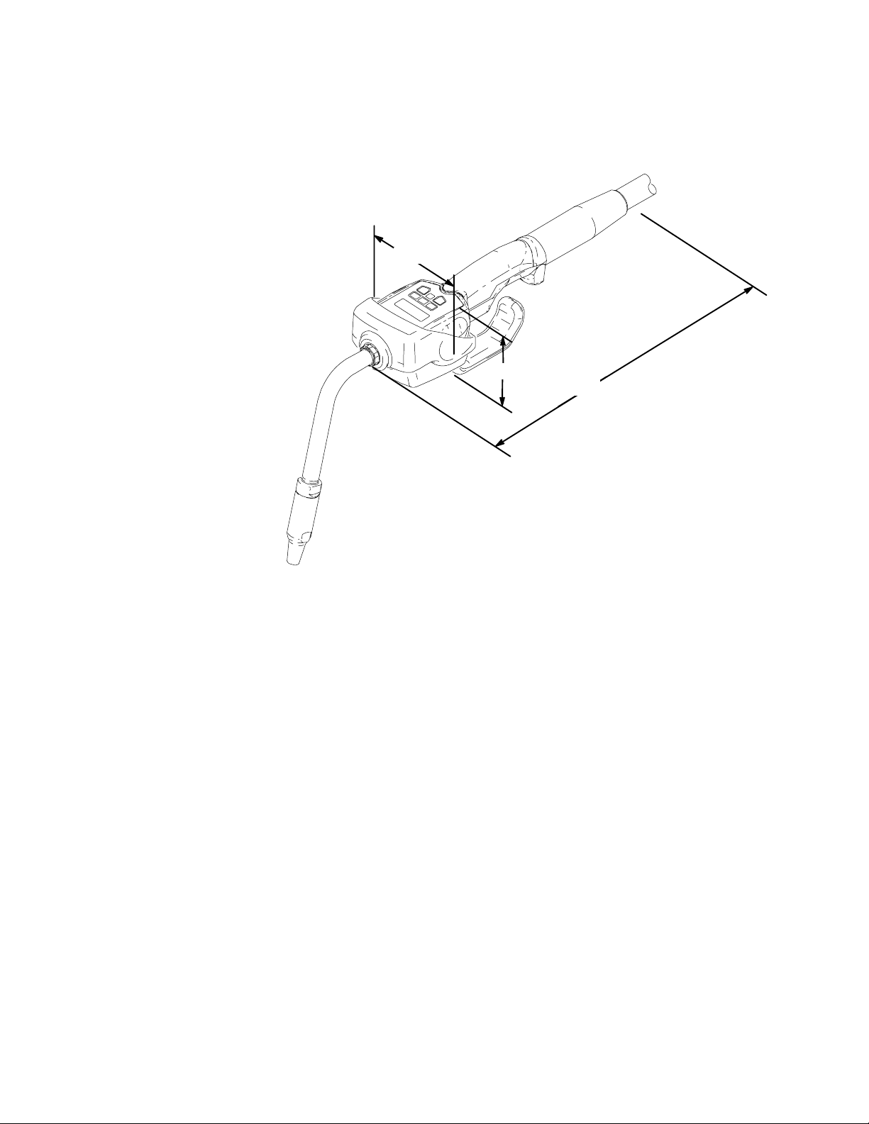
Dimensional Drawing
14.0 in. (356 mm) outlet to end of swivel cover
A
BC3.75 in. (95 mm) widest cross section (including impact guard)
3.10 in. (79 mm) keypad to bottom of impact guard
B
C
A
TI0327
21309377
Page 22

Graco Standard Warranty
Graco warrants all equipment manufactured by Graco and bearing its name to be free from defects in material and workmanship on the
date of sale to the original purchaser for use. With the exception of any special, extended, or limited warranty published by Graco,
Graco will, for a period of two (2) years from the date of sale, repair or replace any part of the equipment determined by Graco to be
defective, including defects in the electronic meter control, which will be repaired or replaced for two (2) years from the date of sale.
This warranty applies only when the equipment is installed, operated and maintained in accordance with Graco’s written recommendations.
This warranty does not cover, and Graco shall not be liable for general wear and tear, or any malfunction, damage or wear caused by
faulty installation, misapplication, abrasion, corrosion, inadequate or improper maintenance, negligence, accident, tampering, or substitution of non-Graco component parts. Nor shall Graco be liable for malfunction, damage or wear caused by the incompatibility of
Graco equipment with structures, accessories, equipment or materials not supplied by Graco, or the improper design, manufacture,
installation, operation or maintenance of structures, accessories, equipment or materials not supplied by Graco.
This warranty is conditioned upon the prepaid return of the equipment claimed to be defective to an authorized Graco distributor for
verification of the claimed defect. If the claimed defect is verified, Graco will repair or replace free of charge any defective parts. The
equipment will be returned to the original purchaser transportation prepaid. If inspection of the equipment does not disclose any defect
in material or workmanship, repairs will be made at a reasonable charge, which charges may include the costs of parts, labor, and
transportation.
THIS WARRANTY IS EXCLUSIVE, AND IS IN LIEU OF ANY OTHER WARRANTIES, EXPRESS OR IMPLIED, INCLUDING BUT
NOT LIMITED TO WARRANTY OF MERCHANTABILITY OR WARRANTY OF FITNESS FOR A PARTICULAR PURPOSE.
Graco’s sole obligation and buyer’s sole remedy for any breach of warranty shall be as set forth above. The buyer agrees that no other
remedy (including, but not limited to, incidental or consequential damages for lost profits, lost sales, injury to person or property, or any
other incidental or consequential loss) shall be available. Any action for breach of warranty must be brought within three (3) years of
the date of sale.
Graco makes no warranty, and disclaims all implied warranties of merchantability and fitness for a particular purpose in connection
with accessories, equipment, materials or components sold but not manufactured by Graco. These items sold, but not manufactured
by Graco (such as electric motors, switches, hose, etc.), are subject to the warranty, if any, of their manufacturer. Graco will provide
purchaser with reasonable assistance in making any claim for breach of these warranties.
In no event will Graco be liable for indirect, incidental, special or consequential damages resulting from Graco supplying equipment
hereunder, or the furnishing, performance, or use of any products or other goods sold hereto, whether due to a breach of contract,
breach of warranty, the negligence of Graco, or otherwise.
FOR GRACO CANADA CUSTOMERS
The parties acknowledge that they have required that the present document, as well as all documents, notices and legal proceedings
entered into, given or instituted pursuant hereto or relating directly or indirectly hereto, be drawn up in English. Les parties reconnaissent avoir convenu que la rédaction du présente document sera en Anglais, ainsi que tous documents, avis et procédures judiciaires
exécutés, donnés ou intentés à la suite de ou en rapport, directement ou indirectement, avec les procedures concernées.
Graco Information
TO PLACE AN ORDER, contact your Graco distributor, or call one of the following numbers
to identify the distributor closest to you:
1–800–533–9655 Toll Free
612–623–6928
612–378–3590 Fax
All written and visual data contained in this document reflects the latest product information available at the time of publication.
Graco reserves the right to make changes at any time without notice.
International Offices: Belgium, Korea, China, Japan
Graco Headquarters: Minneapolis
GRACO INC.ąP.O. BOX 1441ąMINNEAPOLIS, MNą55440-1441
MM 309377
www.graco.com
309377 06/2001, Revised 04/2006
22 309377
 Loading...