

Page 1

INSTRUCTIONS-PARTS
This manual contains
WARNINGS
READ
AND
RETAIN
PORTABLE, AIRLESS
IMPORTANT
and
INSTRUCTIONS
FOR
REFERENCE
LIST
GRACO
307-293
Rev.
N
SUPERSEDES M
GH
3000
psi
(210 bar)
433
PAINT
MAXIMUM
WORKING PRESSURE
SPRAYER
Model 215-433, Series G
Includes Sprayer 231-005, Hose, Gun, Tip Guard and
Spray Tip
of
Choice.
Model 231-005, Series A
Sprayer only
INDEX
Warnings
Installation
Flushing Guidelines
Operation
Regular Maintenance
Troubleshooting
Repair
Parts Drawings
Accessories
How
Technical Data
Warranty ... ,
....................................
..................................
....................................
......................................
to
Order Replacement Parts
.......................
.......................
.............................
& List
...................................
......
...................
...................
'"
..... , ....
, ... Back Cover
2, 3
4, 5
6,
8, 9
10
11
12-15
16-19
20
........
Back Cover
21
7
~--------------------------------------WARNING-------------------------------------.
Aluminum and Zinc Material Hazard
Never
use
such solvents in this equipment.
plosion, which
Consult your
1,1, 1-trichloroethane, methylene chloride, other halogenated hydrocarbon solvents or fluids containing
could cause death, serious bodily injury
fluid suppliers
GRACO
INC.
Such
use
could result in a serious chemical reaction, with the possibility
to
ensure that the fluids being used are compatible
P.O.
BOX
©COPYRIGHT
1441
and/or
substantial property damage.
MINNEAPOLIS,
1985
GRACO INC.
with
aluminum and zinc parts.
MN
55440-1444
of
ex-
Page 2

WARNING
HIGH PRESSURE
all
warnings.
SPRAY
Read
and
CAN
CAUSE SERIOUS
understand
all
instruction
FLUID INJECTION HAZARD
General
This equipment generates very high fluid pressure. Spray from
the gun,
through your skin and into your body and
serious bodily injury, including the need for amputation. Fluid
injected or splashed into the
serious damage.
NEVER
body.
try
ALWAYS have the tip guard on the spray
ALWAYS
Safety
leaks or ruptured components
eyes
or on the skin can cause
point the spray gun at anyone or at any part
to
NEVER
"blow
put hand or fingers over the spray tip.
back"
paint; this
follow
the Pressure Relief Procedure, below,
is
NOT
an
air spray system.
gu
can
inject fluid
cause
extremely
of
the
NEVER
n when spraying.
before cleaning or removing the spray tip or servicing any
system equipment.
NEVER
Be
before each use.
Medical
If
MEDICAL
SIMPLE CUT. Tell the doctor exactly what fluid was injected.
try
to
stop or deflect leaks with your hand
sure equipment safety devices
any fluid appears
Note
It
possible.
Alert-Airless
to
Phys/cilln:
is
important
CARE
Do
not
Spray
to
penetrate your skin, get EMERGENCY
AT
ONCE. DO
Injection in the skin is a traumatic injury.
to
treat
the
delay treatment to research toxicity. Tox-
Wound
injury
are
operating properly
NOT
TREAT
surgically
8S
or
soon
body.
AS
A
as
icity is a concern with some exotic coatings injected directly
into the blood stream. Consultation with a plastic surgeon or
reconstructive hand surgeon
Spray Gun
Be
sure all gun safety devices
each
can cause a malfunction and
use.
Safety
Do
Devices
not
remove or modify any part
may
be
advisable.
are
operating properly before
result in serious bodily injury.
of
the gun; this
INJURY.
manuals
For
professional
before
operating
use
only.
equipment.
Observe
Safety Latch
Whenever you stop spraying,
the gun safety
the gun inoperative.
accidental triggering
latch
in
Failure to set the safety latch
of
even
the closed or
the gun.
for a moment, always set
"safe"
position, making
can
result in
Diffuser
The gun diffuser breaks up spray and reduces the risk
injection when the tip
regularly. Follow the Pressure Relief
then remove the spray tip. Aim the gun into a metal pail,
holding
pressure, trigger the gun.
to
Tip
ALWAYS
spraying. The tip guard alerts you
and
your fingers
the gun firmly to the pail. Using the lowest possible
an
irregular stream, replace the diffuser immediately.
Guard
have the tip guard
helps reduce, but does not prevent, accidentally placing
or
is
any part
not
installed. Check diffuser operation
If
the fluid emitted is
in
place on the spray gun while
of
your body close
Procedure,
not
to
the fluid injection hazard
to
of
fluid
below,
diffused in-
the spray tip.
Trigger Guard
Always have the trigger guard in place on the gun when spray-
to
reduce the risk
ing
dropped or bumped.
Spray
Tip
Use
the spray tip clogs while spraying, engage the gun safety latch
immediately.
cedure
NEVER
fully relieved
Safety
extreme caution when cleaning or changing spray tips. If
ALWAYS
and then remove the spray tip
wipe
off
and
of
accidentally triggering the gun
follow the Pressure
build-up around the spray tip until pressure
the gun safety latch is engaged.
to
clean it.
Relief
if
Pro-
it
is
is
Relief
Pressure
To reduce the risk
always follow this procedure whenever you shut
parts,
installing, cleaning or changing spray tips, and whenever you stop spraying.
when
bypass
valve.
metal part
ty
latch. (7) Open the drain valve, having a container ready
ready to spray again.
If
you
suspect
steps above,
completely.
Procedure
of
serious bodily injury, including fluid injection, splashing in the
(3)
Depress the engine stop button.
of
the gun firmly
to
the side of-a grounded metal pail, and trigger the gun
off
the sprayer, when checking or servicing any part
(4)
Close the fuel shutoff valve.
to
catch the drainage.
that the spray tip or hose is completely clogged, or that pressure has
VERY SLOWLY loosen the tip guard retaining
Now
clear the tip
or
hose.
/4
nut
or hose end coupling and relieve pressure gradually, then loosen
eyes
or on the skin, or injury from moving
(1)
Engage the gun safety latch.
(5)
Disengage the gun safety latch and hold a
to
relieve pressure.
(8)
Leave
the drain valve open until you
not
been
fully
5
of
the spray system,
(2)
Open the
(6)
Engage the gun safe-
relieved after following the
are
2 307-293
Page 3

EQUIPMENT MISUSE
General
Any
overpressurizing, modifying parts, using incompatible
chemicals and fluids, or using worn or damaged parts,
cause
serious bodily injury,
NEVER
could cause
CHECK
worn or damaged parts immediately.
Read
regarding the use
System
This sprayer
WORKING
accessories
pressure
ing pressure
system.
Fluid
BE
patible with the wetted parts shown
the back cover. Always
turer's literature before using them
HOSE
High pressure fluid in the hoses
hose develops a
damage or misuse, the high pressure spray emitted from
cause a fluid injection injury or other serious bodily injury or
property damage.
ALL
BOTH ENDSI
kinks or bends at or close
hose rupture.
TIGHTEN
pressure fluid can dislodge a loose coupling or
pressure spray
NEVER
hose
movement
exist, replace the hose immediately.
high pressure hose or mend
repaired hose cannot contain the high pressure fluid.
HANDLE AND
hoses
are
DO
or
Hose
Proper hose grounding continuity
grounded spray system. Check the electrical resistance
air and fluid hoses at least once a week.
have a tag on it which specifies the maximum electrical
resistance, contact the hose supplier or manufacturer
maximum resistance limits. Use a
propriate range for your hose to check the resistance.
resistance exceeds the recommended limits, replace
mediately. An ungrounded
your system hazardous. Also
HAZARD,
Safety
misuse
of
the spray equipment or accessories, such
them
to
rupture and result in fluid injection or other
alter
or
modify any part
it
to
all
spray equipment regularly and repair
and follow the fluid and solvent manufacturer's literature
Preb Jure
can
PRESSURE.
are
of
Compatibility
SURE
rated
this sprayer.
of
that all fluids and solvents
SAFETY
leak, split or rupture due
FLUID HOSES
for
to
not
NOT expose the hose to temperatures above 180°F (82°C)
below
Grounding
The spring guards help protect the hose from
all
fluid connections securely before
to
use a damaged hose.
cuts, leaks, abrasion, bulging cover, or damage or
of
the hose couplings.
ROUTE HOSES CAREFULLY.
move equipment. Do not
compatible
-40°F (-40°C).
to the right.
HAZARD
fire, explosion or property damage.
of
malfunction.
of
protective clothing and equipment.
develop 3000
Be
sure that
to
withstand the maximum working
DO
any component or accessory used
read
MUST
to
be emitted from the coupling.
it
with
the inner tube and cover
Continuity
or
this equipment; doing
or
psi
(210 bar)
all
spray equipment and
NOT exceed the maximum work-
used
are
in
the fluid and solvent manufac-
HAVE
the coupling which
Befo.re
with tape or any other device. A
poorly grounded hose
the Technical Data on
in
this sprayer.
can
be
very dangerous. If the
to
SPRING
each use, check entire
If
any
DO
NOT try
use
fluids
is
essential
If your hose does
voltage 'meter in the ap-
read
FIRE OR EXPLOSION
MAXIMUM
chemically com-
any kind
GUARDS
can
each
use. High
allow high
of
these conditions
to
Do
not pull on
or
solvents which
of
the hose.
to
maintaining a
can
as
can
so
replace
in
the
of
wear,
it
can
ON
result in
recouple
of
your
not
for
the
If
the
it
im-
make
MOVING PARTS HAZARD
Moving parts can pinch or amputate your fingers or other
body parts.
operating the sprayer.
on page 2 before checking or servicing the sprayer to prevent
it
from starting accidentally.
KEEP
CLEAR
of
Follow the Pressure
moving parts when starting or
Relief
Procedure
,," IMPORTANT
United States Government' safety standards have been
adopted under the
standards-particularly the General
the Construction Standards, Part
Occupational Safety and Health Act. These
Standards, Part
1926-should
1910,
be
consulted.
and
FIRE
OR
EXPLOSION
Static electricity
through the pump and hose.
ment
is
system may become hazardous. Sparking may also occur
when plugging
can
dust particles and other flammable substances, whether you
are
plosion and serious bodily injury and property damage.
Always locate the sprayer at least
spray area.
the spray
in the air.
If
while using this equipment,
MEDIATELY.
ding.
identified and corrected.
Grounding
To reduce the risk
all
CHECK
structions
ground
1.
not
ignite fumes from solvents and the fluid being sprayed,
spraying indoors or outdoors, and
you experience any static sparking or even a slight shock
Do
not
other spray equipment used or located in the spray area.
your local electrical code
all
Sprayer: connect the ground wire and clamp (provided) to
a true earth ground.
is
properly grounded, sparking may occur, and the
in
Do
not
area
when there
Check the entire system for positive groun-
use
the system again until the problem
for
your
of
this spray equipment:
HAZARD
created by the high velocity
or
unplugging a power supply cord. Sparks
plug in or unplug any power supply cords in
of
static sparking, ground the sprayer and
area
If
every part
is
any chance
and type
See
Fig
can
20
feet
(6
of
STOP
for
detailed grounding in-
of
equipment.
1.
flow
of
of
the spray equip-
cause a fire
m) away from the
igniting fumes still
SPRAYING
BE
fluid
or
IM-
has
been
SURE to
ex-
o
o
o
Fig 1
2.
Fluid hoses:
500
feet
ing continuity. Refer to the section Hose
tinuity.
3.
Spray gun: obtain grounding through connection
perly grounded fluid hose and sprayer.
4. Object being sprayed: according to local code.
5.
Fluid supply container: according
6.
All
solvent pails
code.
place the pail on a non-conductive surface, such
or cardboard, which interrupts the grounding continuity.
7.
To
maintain grounding continuity when flushing
ing pressure,
the side
Flushing
Reduce the risk
splashing by
on page 6
cedure
Hold a metal part
pail and use the lowest possible fluid pressure during
metal
flushing.
GAS
ENGINE HAZARDS
NEVER
Fuel
spilled on a hot surface can ignite and
AL
WA
YS pour fuel
NEVER operate the engine in a closed building unless the
engine exhaust
monoxide, a poisonous, odorless and invisible
cause
serious illness and
NEVER alter the throttle setting which
maximum
with this
use
(150
Use
of
Safety
of
on page 2, and remove the spray tip before flushing.
fill the fuel tank while the engine
full load engine
can
only grounded hoses with a maximum
m)
combined hose length to ensure ground-
used
only
always hold a metal part
a
grounded
of
following the specific flushing procedure given
this manual. Follow the Pressure
of
is
piped outside. The exhaust contains carbon
damage the sprayer and will void the warranty.
when flushing, according
metal
pails, which are conductive.
metal pail, then trigger the gun.
fluid injection injury, static sparking, or
the gun firmly to the side
in
slowly to avoid spilling.
even
death
speed
of
Grounding
to
local code.
of
the gun firmly to
of
is
running or hot.
if
2800
gas
inhaled.
is
factory set at the
RPM. Tampering
Relief
a grounded
cause
which
to
to
as
or
Con-
a pro-
local
Do
not
paper
reliev-
Pro-
a fire.
can
of
307-293
3
Page 4
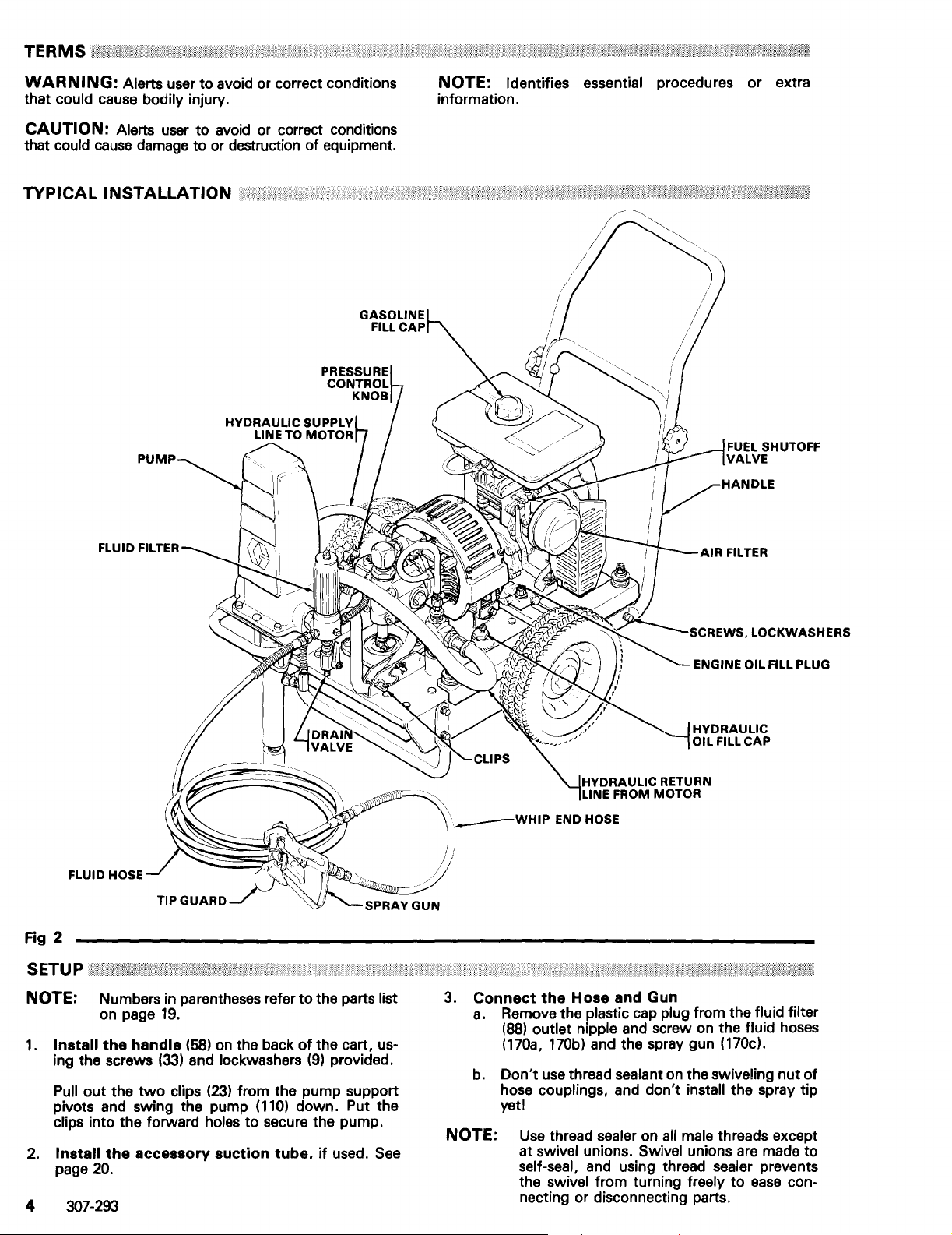
TERMS
WARNING:
that
could cause bodily injury.
Alerts user to avoid or correct conditions
CAUTION: Alerts user
that
could
cause
damage to or destruction
TYPICAL
INSTALLATION
to
avoid or correct conditions
of
equipment.
NOTE: Identifies essential procedures or extra
information.
FUEL SHUTOFF
VALVE
FLUID HOSE
Fig 2
SETU P
U;;ti/'WH:nA
NOTE: Numbers in parentheses refer
on page
1.
Install
the
ing the screws
out
Pull
the
pivots and swing the pump
clips into the forward
2.
Install
page
the
20.
4 307-293
19.
handle
two
(58)
(33)
and lockwashers
clips
accessory
on
the back
(23)
from the pump support
(110)
holes
to
secure the pump.
suction
tube,
to
the parts list
of
the cart, us-
(9)
provided.
down. Put the
if
used.
See
'
___
)
I
3.
Connect
a.
b.
NOTE:
~
IHYDRAULIC
--,
WHIP
HYDRAULIC RETURN
FROM MOTOR
LINE
END HOSE
the
Hose
and
OIL FILL
Gun
CAP
Remove the plastic cap plug from the fluid filter
(88)
outlet nipple and screw on the fluid hoses
(170a,
170b) and the spray gun (170cl.
Don't
use thread sealant on the swiveling
nut
of
hose couplings, and don't install the spray tip
yeti
Use
thread sealer on
swivel unions. Swivel unions
at
all
male threads except
are
made
to
self-seal, and using thread sealer prevents
swivel from turning freely
the
to
ease
con-
necting or disconnecting parts.
Page 5

4. Fill
5.
the
Packing
the
Seal
Hydraulic
to
it
in the hole, but do not thread
oil should
Graco Throat
Check
a.
Unscrew the oil fill cap.
is
attached
and set
place. The
Nut/Wet
Cup
Liquid nsu, supplied.
Oil Level
See
the cap. Wipe
be
up
dipstick.
------CAUTION
To prevent damage
hydraulic pump,
part no. 169-236
207-428
oil
b. Add
(1
gaI.l3.8Iiter).
may damage the hydraulic components.
oil
as
pletely full hydraulic system contains about
2-1/2 gallons (9.5 liter)
to
the cooling
use
only Graco Hydraulic
(5
gal.l20
Other types
needed
to
the proper level. A com-
of
(141)
1/4
Fig
3.
The dipstick
off
the dipstick
to
the full line on the
------..,
syster:n
liter) or part
of
hydraulic
oil.
full with
it
in
a~d
011,
nc.>.
6.
Check
a.
b.
the
Engine
Oil Level
Unscrew the oil fill plug.
is
dipstick
Without
attached
threading the plug into place, check
be sure the oil
is
to
up
to
See
Fig
the plug.
the
top
3 and 4. The
mark on the
dipstick.
If oil
is
c.
needed,
recommended
RECOMMENDED ENGINE
detergent
regular use and
SEASON
Spring, Summer,
7.
oil classified "FOR SERVICE
for
GRADE
OR
TEMPERATURE
30°F
to
Winter
Crankcase capacity:
Fill
the
Fuel
Tank
see
the chart below
oil type and weight.
OIL:
Use
the breaking-in
OF
ENGINE
OIL CHART
Autumn
0°
1-1/4 pints (0.6 liters)
a high quality,
SO
of
a new engine.
GRADE
SAE
SAE 10W-30
.-------WARNING-----
Fuel
spilled on a
plosion and cause serious bodily injury and pro-
perty
damage. Always shut
it
cool before filling the tank, and carefully follow
steps 7.a.
fuel.
any
hot
surface
to
7.c., below, being sure not
can
cause a fire or ex-
off
the engine and let
or
for
SE",
OF
30
to
to
the
for
OIL
...
spill
Fig 3
_______________
@
Fig 4
_______________
HYDRAULIC
OIL
FILL
CAP
ENGINE OIL
PLUG
FILL
100
IN PLACE TO
CHECK
NOT THREAD
LEVEll
a. Close the fuel shutoff valve.
b.
Use
only clean, fresh well-known brands
unleaded regular grade gasoline. The
octane requirements are 86 octane
U.S.A.
c. Remove the
which
Be
_
8.
so
the cap.
Grounding
and 96 octane elsewhere.
gasoline fill cap and fill the tank,
holds about 1 gallon (3.8 liters)
sure the air vent in the fill cap
fuel can
flow
See
to
the carburetor, then replace
Fig
2.
WARNING-----
To reduce the risk
of
static sparking, fire or explo-
See
Fig
3.
mi~imum
of
is
not
plugged
In
of
the
fuel.
...
sion which can result in serious bodily injury and
property damage, always ground the
~prayer
and
system components, and the object being sprayed
as
instructed under FIRE OR EXPLOSION
HAZARD
9.
Flush
in the pump after factory testing
pump from corrosion.
_
on page
on page
the
6.
sprayer
3.
to
remove the oil which was left
See
"Flushing Guidelines"
to
protect the
307-293 5
Page 6
FLUSHING GUIDELINES
When
1.
to
Flush
New
Sprayer. Your new
tory tested in lightweight oil which was left in
protect pump parts from corrosion.
GH
433
Sprayer was fac-
to
Before using oil-base paint, flush with mineral
spirits only.
Before
spirits,
rinse.
2.
Changing
such
3.
Changing
Flush
4.
Changing
Flush
then a clean water flush.
How
------------WARNING----------~
Follow the Pressure
on page 2 or
flushing.
1.
Be
is
2.
Pour enough clean, compatible solvent into a large,
empty,
using water-base paint, flush with mineral
followed by soapy water, then a clean water
Colors.
as
mineral spirits.
from
with
soapy water, then mineral spirits.
from
with
mineral spirits, followed by soapy water,
to
Flush
B.
sure the gun safety latch
Flush with a compatible solvent
water-base
oil-base
Relief
Then remove the spray tip before
to
oil-base
to
water-base
Procedure
is
engaged, and there
Warning
no spray tip in the gun.
metal pail
to
fill the pump and hoses.
paint.
paint.
3. Place the accessory suction tube into the pail or tilt
the sprayer back (it will support itself) and place the
pail under the pump. Then tilt the sprayer forward
to
lower the pump into the pail.
4. Turn the pressure control knob counterclockwise
until all spring tension
feel it. The sprayer
setting. Turning the knob further will cause it
off. Tighten the knob locknut
5. Open the bypass valve. The lever will
the body
of
the valve.
is
relieved. You will
is
now
set at the lowest pressure
to
set.
See
Fig
5.
See
be
be
able
to
Fig
5.
parallel
fall
to
to
5.
Storage.
Water-base paint: flush with water, then mineral
spirits and leave the pump, hose and gun filled
mineral spirits
Pressure
Relief
to
prevent corrosion. Follow the
Procedure
Warning
on page 2 or
B.
Oil-base paint: flush with mineral spirits. Follow
the Pressure
2 or
B.
6.
Startup
Before using water-base paint, flush out mineral
spirits with soapy water and then a clean water
flush.
When using oil-base paint, flush out the mineral
spirits with the fluid
ready
to
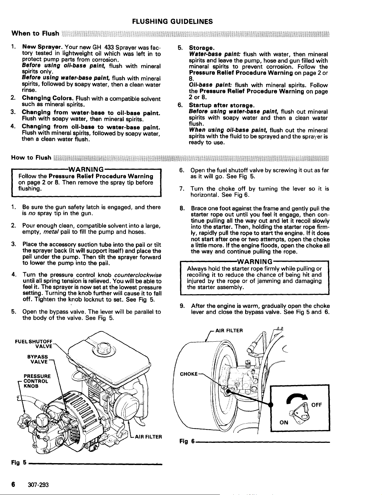
6. Open the fuel shutoff valve by screwing it
as
it will go.
7. T urn the choke
horizontal.
B.
Brace one
starter rope
tinue pulling
into the starter. Then, holding the starter rope firmly, rapidly pull the rope
not start after one or
little more.
a
the way and continue pulling the rope.
---------WARNING-------..
Always hold the starter rope firmly while pulling or
recoiling
injured by the rope or
the starter assembly.
9.
After the engine
lever and close the bypass valve.
Relief
Procedure
after
storage.
to
use.
See
See
foot
out
all the way out and let
If
the engine floods, open the choke all
it
to
reduce the chance
be
Fig
5.
off
by turning the lever
Fig
6.
against the frame and gently pull the
until you feel
to
two
of
is
warm, gradually open the choke
Warning
sprayed and the sprayer
it
engage, then con-
it
recoil slowly
start the engine.
attempts, open the choke
of
jamming and damaging
being hit and
See
Fig
with
on page
out
as
so
it
If
it
does
5 and 6.
is
far
is
Fig 5
______________
6
307-293
....
CHOKE
ON~
Fig
6-----------------
~~OFF
Page 7

10.
Point the gun into the metal pail and hold a metal
of
part
..-----~WARNING-----..,
To reduce the risk
cause fire or explosion, always
the gun firmly against the pail.
of
static sparking, which can
hold a metal part
See
the gun firmly against a grounded metal pail when
flushing. This
also reduces splashing.
Fig
of
7.
11.
Disengage the gun safety latch and squeeze the
gun trigger.
pressure control knob clockwise just enough
start the pump. See
A"ow
12.
At
the pump
the same time, slowly turn the
to
Fig
5.
to
operate until clean solvent
comes from the gun.
13. Release the trigger and engage the gun safety
latch.
Fig 7
-----------------
MAINTAIN
METAL
CONTACT WHEN
FLUSHING
TO
FIRM
METAL
14.
If
you
are
going
to
start
spraying,
place the
pump or accessory suction tube into the supply
container.
Release
the gun safety latch and trigger
the gun into another empty, metal container,
of
holding a metal part
the gun firmly against the
metal pail, and force the solvent from the pump and
hose. Engage the gun safety latch until you are
to
15.
ready
If
you
prime the pump
are
going
to
(see
store
Step 3, page 9).
the
sprayer,
the accessory suction tube or pump from the sol-
of
vent pail, holding a metal part
the gun firmly
against the metal pail, and force the solvent from
the pump and hose. Engage the gun safety latch.
to
the
Refer
"When
16.
Whenever
Pressure
"Storage"
To Flush",
you
shut
Relief
Procedure
procedure in the section
see
page 6.
off
the
sprayer,
Warning,
follow the
on page 2
or 8.
remove
307-293 7
Page 8

Pressure
To reduce the risk
from moving parts, always
any part
Engage the gun safety latch. (2) Open the bypass valve. (3) Depress the engine stop button. (4) Close the fuel
shutoff valve.
metal pail, and trigger the gun
a container ready
If
you suspect
following the steps sbove, VERY SLOWLY loosen the tip guard retaining nut or hose end coupling and relieve
pressure gradually, then loosen completely.
of
;/
""
~'\../
Relief
/\
Procedure
of
serious bodily injury, including fluid injection, splashing in the eyes or on the skin, or injury
follow this procedure whenever you shut
the spray system, when installing, cleaning or changing spray tips, and whenever you stop spraying. (1)
(5) Disengage the gun safety latch and hold a metal part
to
catch the drainage. (8)
thst
the sprsy tip
/\
to
relieve pressure. (6) Engage the gun safety latch. (7) Open the drain valve, having
or
hose is completely clogged,
~
WARNING
Lea(ve
the drain valve open until you are ready
Now
clear the tip or hose. 5
./3
--------------~
off
the sprayer, when checking or servicing
of
or
the gun firmly
thst
pressure hss
\_
,"
c~
to
the side
to
spray again.
not
been fully relieved
of
a grounded
sfter
~~\1.'\~
"/
1. Prepare
a.
Prepare the fluid according
manufacturer's recommendations.
b. Place the pump or accessory suction tube into
the fluid container.
2.
Starting
a.
Open the bypass valve to make startup easier.
In
the open position, the valve lever
to
the body
the filter drain valve.
b. Turn the pressure control knob
wise
be
able
lowest pressure setting. Turning the knob further
c.
Open the fuel shutoff valve
tion.
d.
If
the engine
the lever in the direction of the arrow.
e.
Brace one
pull the starter rope until you feel
then continue pulling
recoil slowly into the starter. Then, holding the
starter rope
the engine.
attempts, open the choke a little more. If the
engine
continue pulling the rope.
1
the
Fluid
the
Sprayer
of
the valve. Refer
until all spring tension
to
feel it. The sprayer is
will cause
See
floods, open the choke all the way and
it
to
fall off.
Fig
8.
is
cold, close the choke by turning
foot
against the frame and gently
all the way out and let
firmly, rapidly pull the rope
If
it
does not start after one or
~
to
the fluid
is
to
Fig
counterclock-
is
relieved. You will
now
set at the
to
a vertical posi-
See
it
parallel
8. Close
Fig
9.
engage,
to
start
two
it
FUEL
Fig 8
SHUTOFF
VALVE
_______________
7
_
r--~----WARNING
Always hold the starter rope firmly while pulling or
recoiling it
injured by the rope or of jamming and damaging
the starter assembly.
8
307-293
to
reduce the chance
-------.
of
being hit and
Fig 9
______________
~~
OFF
ON~
_
Page 9

f. After the engine is warm, gradually open the
choke lever and close the
8 and
9.
NOTE: In cold weather, run the engine
minutes with the bypass valve open before
starting the displacement pump
hydraulic motor stalling.
avoid
g. Follow the Pressure
Ing,
on page 8,
to
Relief
shut
off
bypase valve.
for
Procedure
the sprayer.
-------WARNING------
To
stop
the
engine
the engine STOP button. Close the bypass valve
possible. See Fig 8. Then relieve the fluid pressure
in the pump and hose
sure
Relief
3.
Prime
a.
Be
b. Don't
c.
If
procedure in
d. Disengage the gun safety latch.
e.
Point the gun into a metal pail and hold a metal
part
10.
f. Squeeze the trigger and slowly turn the
pressure control knob
start the pump.
g.
Operate the pump until all air
pump and hoses and fluid is flowing freely from
the gun.
h. Release the trigger and engage the gun safety
latch.
L Turn the pressure control knob counterclock-
wise
be
lowest pressure setting. Turning the knob further will cause it
j.
Follow the Pressure
ing
gun
instruction
Procedure
the
Pump
sure the gun safety latch
install the spray tip yeti
the engine has not been started, follow the
of
the gun firmly against the pail.
until all spring tension
able
to
on page
as
instructed in your separate gun or nozzle
-------CAUTION
DO
NOT move the sprayer while the engine is
operating. Tilting the sprayer during operation will
cause lubrication problems.
in
an
emergency,
as
instructed in the Pres-
Step
Warning,
2,
page
on page
is
8.
engaged.
clockwise just enough
See
Fig
8.
is
purged from the
is
feel it. The sprayer
to
fall off.
8.
manual.
Relief
Then install the spray tip in the
relieved. You will
is
now
Procedure
------
MAINTAIN
METAL
CONTACT WHEN
FLUSHING
TO
depress
See
Fig
about
15
to
help
Warn-
if
8.
See
Fig
to
set at the
Warn-
FIRM
METAL
4.
Adjusting
a.
Turn the pressure control knob clockwise
crease and
pressure. Tighten the knob locknut
b. Always use the lowest pressure necessary
completely atomize the fluid.
-------CAUTION
Operating the sprayer at a higher pressure than
needed wastes fluid, causes early tip wear, and
shortens sprayer life.
c.
If
rather than increasing the pressure.
d. Check the spray pattern. The tip
determine the pattern width and
Refer
ed
-------CAUTION
The engine throttle
2800 RPM. The sprayer warranty will
and the
justment
5.
Cleaning a Clogged
---~-.-..;WARNING------
To reduce the risk
NEVER
the spray tip when cleaning or checking
cleared tip. Always point the gun toward the
ground or into a waste container when checking
see
to
clearing tip.
a.
Follow the Pressure
ing
b. Clean the front
day
the tip. To clean, and
while
nozzle instruction
cedure.
6.
When
a.
Whenever you stop spraying, even
( break,
Warning
b.
Clean the
separate gun instruction
c. Flush the sprayer at the end
the fluid you are spraying
could harden in the sprayer overnight.
vent
an
d.
the
Pressure
counterclockwise
to
to
-----
more coverage is needed,
to
the separate instruction manual receiv-
with
your gun.
use
a larger tip
size
flow
-----
has
been set and locked at
hydraulic pump life shortened
is
changed.
Tip
of
a fluid injection injury,
hold your hand, body, or rag in front
if
the tip was cleared or when using a self-
Relief
on page
to
spraying, refer
Shutting
"Flushing"
to
oil-based solvent such
help prevent pump corrosion. Be
relieve
with
mineral
For
long term shutdown or storage, always fill
the sprayer
corrosion. Be
pump
8.
of
keep fluid from building up and clogging
follow the Pressure
on page 8.
tip
flush, then fill the pump and hoses with
pressure
after
the tip frequently during the
to
clear a tip
to
your separate gun or
manual for the proper pro-
Off
the
Sprayer
and gun
on page
with
sure
filling
as
recommended
manual.
6.
Use a compatible sol-
in
spiritsl
the
mineral spirits
to
relieve
it
with
is
be
if
this ad-
Procedure
Relief
of
water-based
as
pump
mineral
for
Procedure
each work day
mineral spirits
after
to
prevent pump
pressure
to
in-
decrease
set.
to
.......
and angle
rate.
....
voided
of
for
a
Warn-
if
it clogs
a short
by
your
or
if
See
to
sure
to
filling
in
the
spirits/
if
it
Fig
10
________________
_
307-293 9
Page 10

1.
Always
stroke
day. This
and damaging the packings.
2.
Keep
nut/wet-cup
helps
3.
Check
should be tight enough to stop leakage,
tighter. Overtightening will damage the packings.
stop
the
when you take a break and at the end
helps keep fluid from drying on the rod
the
protect the packings and rod.
the
tightness
pump a the
displacement
1/4
full
of
TSL at
of
the
bottom
pump
all
times. The TSL
packing
nut
packing
------CAUTION------
Proper engine and hydraulic oil level
to prevent
as
often
4.
Check
must be up
only Graco Hydraulic Oil,
5.
Check
oil must
the fill cap unthreaded.
more than one ounce
Consult the engine manual, supplied, for additional
recommended maintenance.
costly damage
as
recommended
tha
hydraulic
to
the top mark on the dipstick (25).
the
engine
be
up
to
to
the sprayer. Check it
in
Steps 4 and 5, below.
oil
level
see
oil
level
the top mark on the dipstick with
The
engine should not
of
oil per hour
is
important
weekly.
ACCESSORIES.
at
least
weekly.
of
operation.
of
of
the
daily.
but
The oil
Use
The
use
Its
It
no
8.
To
change
a.
Follow the Pressure Relief
Ing,
ceeding.
Place a waste container under the drain plug (7)
b.
of
the
plug before proceeding.
c.
Remove the nuts (4) and reservoir (66).
d. Remove the return line filter (55) and install a
new filter assembly.
e. Inspect the inlet filter (21)
f. Install the reservoir and nuts. Then pour
2-1/2
through the dipstick hole (25),
stall
the
hydraulic
on
page 8. Allow the oil to cool before pro-
the hydraulic reservoir.
plug, and drain the reservoir. Reinstall the
gallons (9.5 liters)
the dipstick.
oil:
Procedure
See
Fig
11. Unscrew
and
replace
of
Graco Hydraulic
See
Fig
Warn-
if
needed.
11. In-
in
Oil
6.
Inspect
clogging. Replace it after every
tion or every six months, whichever comes first. A
clogged or worn
and will damage the hydraulic pump.
7.
Change
of
first. For continuous operation in temperatures
above 85°F (30°C), change the oil after every 1000
hours or six months
cedure.
------CAUTION
Cleanliness
hydraulic system.
ting dust or dirt into the hydraulic system to prevent damage to the
the
return
out
the
operation or every
hydraulic
is
essential when servicing the
Use
hydraulic components.
line
filter. (65)
filter reduces filter capability
oil
after
12
months, whichever comes
of
use.
Refer to Step 8
frequently
500
hours
every
2000 hours
-----
special care
to
avoid get-
of
for
for
opera-
pro-
.......
Fig
11
_______________
_
10 307-293
Page 11

~-----------------------------WARNING------------------------------~
To reduce the risk
from moving parts,
troubleshooting
of
serious bodily injury, including fluid injection, splashing in the eyes or on the skin, or injury
always
or
repairing your sprayer.
follow
the Pressure Relief Procedure Warning
as
given on page 2
or
8 before
Check everything in the Troubleshooting Chart before disassembling the sprayer.
TROUBLESHOOTING
PROBLEM
Gas
engine doesn't work properly.
Gas
engine operates,
ment pump doesn't operate.
Displacement pump operates, but Piston
output
is
low
on upstroke.
Displacement pump operates but out- Piston packings worn or damaged.
put
is
low
both strokes.
Paint leaks into wet-cup.
Excessive
motor piston rod wiper.
Fluid delivery
on downstroke
leakage around hydraulic Piston rod or
is
low.
but
displace-
and/or
on
CAUSE
motor
Hydraulic
Pressure setting
Displacement pump outlet filter (if Clean the filter.
used) dirty
Tip or tip filter (if used) clogged.
Hydraulic fluid
Hydraulic pump worn or damaged.
Hydraulic motor worn or damaged. Return sprayer
Displacement pump rod seized
dried paint.
ball check not seating properly. Service piston ball check.
Piston packings worn or damaged.
Intake valve ball check
properly.
Loose wet-cup.
Throat packings worn or damaged.
Pressure
Displacement pump
used)
Hydraulic pump worn or damaged.
Hydraulic motor wom or damaged. Return sprayer for
Large
setting too low.
dirty or clogged.
pressure drop
stalled. See
too
low.
or
clogged.
too
low. Shut
not
seating Service intake valve ball check. See
seal
worn or damaged.
outlet filter (if
in
fluid hose.
by
SOLUTION
Consult
Increase
Remove tip
mediately. *
page
Tighten just enough to stop
engine manual, supplied.
"Starting
off
Return sprayer
Service pump. See page
Replace packings. See page
Replace packings.
13.
Replace
Replace
the Sprayer;' page 8.
pressure.
sprayer and add fluid im-
packings.
these parts.
and/or
See
page
for
for
See
See
page
filter and clean.
5.
repair.
repair.
13.
See
page
page
See
manual
306-98l.
Increase
Clean
Return sprayer for
Use
pressure.
filter.
larger diameter
repair.
repair.
hose.
9.
See
page
13.
13.
leakage.
13.
13.
Spitting from gun.
*Check the hydraulic fluid
Use
only Graco approved hydraulic fluid;
level
often.
Air entrained
Fluid
supply
Do
not allow it to become too low.
see
page
in
fluid pump or
is
low
5.
or empty.
hose.
Check for loose connections on suction
assembly, tighten, then reprime pump.
supply container.
Refill
307-293
11
Page 12

Disconnect
1.
Solvent flush the displacement pump
Stop the pump on the down stroke.
the
Displacement
Pump
if
possible.
2. Follow the Pressure Relief
on page 8.
3.
Remove the accessory suction tube,
remove the fluid hose from the displacement pump.
Procedure
if
Warning
used, and
4. Unscrew the three tie rod locknuts (114).
5. Remove the lower cotter
6.
Unscrew the displacement rod from the connecting
rod.
7. Pull the pump
Displacement
NOTE:
Packing Repair Kit No. 208-919
for
page
parts in the kit.
off
the tie rods (116).
Pump
servicing the displacement pump.
18.
For the best results,
pin
Service
(1121.
use
is
all
available
See
the new
12 307-293
Fig
12
------
_________
_
Page 13

Intake
1.
2.
Valve
Unscrew the extension (62),
the retaining ring
tension. Clean the parts
(See Fig
(52) and strainer
13)
in
solvent.
if
Screw the intake valve housing
used, and remove
(51)
from the ex-
(138)
out
pump housing (140).
3. Remove the
(125)
and o-ring (133)from the intake valve housing.
4.
Clean
damage, replacing parts
5.
If no further pump service is needed, reassemble
valve and screw
the
quing
Piston,
1.
Cylinder,
Screw the intake valve housing
ball stop pin (132), ball guide (136), ball
all the parts and inspect them
as
needed.
it
to
65
to
75
or
into the pump housing, tor-
ft-Ib (88
Displacement
to
102
N·m).
Rod (See Fig
out
for
of
housing.
2.
Loosen the packing nut
ment rod
3. Secure the rod
(139)
4.
Remove the ball (124), retainer (130), glands (137,
135)
(142)
down and out
in
out
of
the displacement rod.
and packings
(141)
and push the displace-
of
the housing.
a vise and screw the piston stud
(127,
131).
of
the
wear or
13)
the pump
USE WRENCHES
ON FLATS ONLY
135
31
LIPS
.~~-----=:::...<-...,
OFTHE
V-PACKINGS
MUST
FACE
DOWN
137
THROAT
PACKINGS
124
30
127
LIPS
OF
THE
FACE UP
a---'~'
V-PACKINGS
MUST
35
139
TORQUE TO
66-76 ft-Ib
(88-102 N·m)
5.
Clean
all parts and inspect them carefully
or damage. Inspect the outside
inside
of
these parts
if
needed. A worn rod or cylinder will
cause premature wear
Stack a female gland (135), one PTFE v-packing
6.
(131)
and four leather v-packings (127), male gland
(137)
and packing retainer
Be
sure the lips
7.
the cvlinder
Grease
(124)
Torque
NOTE:
the outside
on the piston, and install the piston in the rod.
to
65
to
If
you
are
for
of
of
the v-packings face UP.
of
the packings, place a ball
75 ft-Ib (88
installing a new sleeve, be sure
of
the rod and the
scoring or wear. Replace
the packings.
(130)
on
the piston stud.
to
102
N·m).
for
wear
to
install it with the tapered end down and
(128)
place a new gasket
and housing.
If
the old sleeve cannot be
between the sleeve
removed easily, contact your nearest Graco
Factory Branch or
Service Depot.
8. Slide the displacement rod up into the housing from
it
the bottom until
protrudes from the packing nut.
Reinstall the intake valve.
Throat
1.
Packings
(See Fig
13)
Screw the intake valve housing out
of
the pump
housing.
2. Remove the piston and rod
as
explained above.
INTAKE
VALVE
Fig
13-------
6.
Loosely install the packing nut/wet-cup (141).
7.
Reinstall the displacement rod and intake valve.
Reassembly
1.
Secure the displacement rod to the motor
(See
Fig
_______
12)
cotter pin (112).
2. Secure the pump housing
and tighten the tie rod locknuts
50 ft-Ib
(47
to
68 N·m).
(140)
to the tie rods
(114)
evenly
3. Tighten the packing nut just enough
leakage,
with
TSL.
but
no
tighter.
Fill
the wet-cup
PISTON
VALVE
with
to
to
1/4
_
(116)
35
to
stop
full
a
(131,
127)
3. Remove the pac kings
137)
from the throat
4.
Clean
the throat.
5. Grease the inside
of
of
the pump housing (140),
the packings, then install the
and glands (135,
male gland (137), four leather v-packings (127), one
PTFE v-packing
(131)
and the female gland
(135), one at a time into the throat, being sure they
"nest"
face
properly.
DOWN.
Be
sure the lips
of
the v-packings
4.
Install the extension
(62)
assembly or accessory
suction tube.
5.
Start the pump and operate it slowly to check the
tie rods
necessary,
6.
Reinstall the pump in its mounting.
for
binding. Adjust the tie rod locknuts,
to
eliminate binding.
if
7. Before operating the pump, reconnect the sprayer
ground wire
if
it
was disconnected during repair.
307-293
1~
Page 14

Replacing the Hydraulic Pump
1.
Follow the Pressure Relief Procedure Warning
on page 8. Let the hydraulic system cool before
beginning the service procedure.
9.
Be
sure the new hydraulic pump
as
number
stamped on the pumps
the old one. Check the numbers
to
verify them.
has
the same part
2. Unscrew the reservoir drain
tainer ready
3.
Disconnect the hydraulic inlet hose
swivel
4. Disconnect the bypass
(84).
5.
Remove the four nuts
on the reservoir cover (90).
6.
Remove the
washers (98)
7.
Pull the pump away and loosen the setscrews (38a)
on the pump half
8.
Raise
(21)
filter
to
catch the draining fluid.
union
(45)
at the motor and from the tee (54).
two
screws (8), lockwashers
holding the hydraulic pump (70).
of
the pump and turn
which
is
in the oil reservoir.
plug (7), having a con-
(92)
hose
(85)
from the ball valve
(27)
from the seal plate
the coupler (38).
it
to
unthread the inlet
from the 90°
(11)
(160)
and
10.
Remove all fittings from the old pump and install
them on the new pump in the same order.
11.
Install the new pump, being sure
let filter
12.
Check Dimension A
dimension is correct, tighten the setscrews (38a).
(21)
to
the bottom
as
shown in
r-------CAUTION
The correct coupling dimension
improper
spider which will damage the coupler and make
the sprayer
13.
Reconnect the hoses. Reinstall the reservoir plug
(7),
approved
coupler engagement
inoperable.
and refill the reservoir with clean, Graco-
hydraulic oil.
to
of
the pump.
Fig
------.,
is
critical
to
connect the in-
15.
When the
to
the coupler
76
avoid
Fig
90
14
__________________________________
65
_
14
307-293
Page 15

Drive
Unit
1.
Disconnect the hydraulic inlet hose
paint pump's
2. Loosen the coupling
90°
swivel union (45),
disconnect the hydraulic oil drain hose
oil cooler inlet elbow
(See Figs 14 and
Disconnect the bypass hose (85) from the bypass
3.
4.
(84).
valve
Remove the oiler cooler
cooler retaining screw
(2).
drain hose
nut
(42).
Loosen the cooler drain connector
Pull the cooler up, out
5. Remove the locknuts
15)
nut
of
the elbow (41) and
(41).
(69),
the fan guard (76), the
(40) and clamp
of
(27)
from the
(92)
(2) from the
(68),
the housing.
four
mounts (31).
6.
Remove the four locknuts
(160) screws.
plate
(27)
from the filter seal
from the
and the
engine
9.
Insert a hex socket wrench between the blades
the fan wheel (75) and loosen the coupling setscrew
(38a) so you can remove the flexible coupling
and key (38b). Loosen the fan wheel setscrew (X)
and remove the fan wheel (75).
10.
Unscrew the
adapter plate
11. Unscrew the
mounting screws
mounting plate
12.
Replace parts
order
of
four
capscrews
(64) from the engine.
four
locknuts (20) from the engine
(3) and
(65).
as
needed and reassemble in reverse
(34)
lift
the engine
and remove the
disassembly with special attention
following:
NOTE: Set the gap between the
flexible
coupling
(38)
two
halves
at 1/32 in. (0.8 mm)
and tighten the setscrews firmly. See Fig
off
to
of
of
(38)
the
the
the
15.
7. Lift up the entire drive assembly (engine, fan, and
tilt
it
hydraulic pump) and
8. Remove the
(60)
housing
hydraulic pump
to
four
screws
the adapter plate (64) and take the
(70) and cooler housing
forward.
(12)
holding the cooler
off
of
the
engine (32).
X
Fig15
TOP
CUTAWAY
OF
COUPLINGS
VIEW
(38)
INSIDE COOLER HOUSING
(60)
________________________________________________________________________
307-293
__
15
Page 16

-
--------;;--;-;::;-----
NO
TE:
and tubing
Corresp~md~nJ1nnections"
" bold letters (A)
re
fer
to
hose
110
el
215-433, Series G
Includes I
Mod "tems2-171
Model
Includes Item
006 Series A
~1-
s 2-169,
41
171
17-"
.....
'j
i"'ll.
69
90
(ref)
78
6
307-293
Page 17

64
Model
Includes Items
433
2~5-
Series G
2-171
Model
Includes Items
006
~1-
Series A
2-169,
171
27
160 --____
102
....
58
307-293
11
Page 18

Ref
No
No.
110
171
123
Includes items
111-142,
Ref
Includes items
124-142
.
,.?--111
117
./'"115
118
(see
306-980
for parts)
142
~
U~130
122
18
140
128~~.
~
129
~
~
307-293
Torque
U
I
Torque
I
to
65-75
(88-102
to
(88-102
~.-=~
137
®'
114
127
..
~
135~.
~::~
ft-Ib~
N'm)
134
133~
136~~132
125~
138~
65-75
ft-lb::C~,_
N'm):
~
td
208-919
(Ord~r
Consists of:
*Use extra packin (
if
Pump
separately).
Ref
No.
124
125
127*
131
133
135
137
stacking
Repair P
Qty.
1
1
6
2
1
2
2
is
loo~e.
arts
ref no.
Kit
127)
in piston
Page 19

PARTS LIST
Model 215-433, Series G
Includes items
REF
PART
NO. NO.
2 215-969
3
100-003 CAPSCREW, hex
4
104-858
6
100-028 LOCKWASHER,
100-040
7
B
100-101
9
100-186
100-188
10
11
100-133
12
100-575
13
160-032 NIPPLE, pipe;
14
100-467
15
100-615
16
100-896 BUSHING, pipe;
17
104-869 SCREW, pnh, seIf·tapping, 10-24 x
18
101-242
19 178-392
20
101-566
21
In-267
23 102-801 CLIP, retaining
25
215-971
27
103-450
28
104-120 CAPSCREW, hex hd;
30
104-761
31
104-766
32
104-788
33
100-001
34 105-180 CAPSCREW, hex hd;
161-401
35
36
104-772 BOLT, carriage;
37
102-782 WASHER, plain;
105-793 COUPLING, flexible 1
38
40
100-014
41
105-457 ELBOW, union; 3/8-18 (fbe) 1
42
104-782
43
100-187
44
154-636 WASHER,
165-470 UNION, 90° adapter;
45
46
156-971
47
158-556
48 160-327
50
104-832 PIN, clevis 2
51
164-717 STRAINER,
164-718
52
53
165-198 NIPPLE, hex reducing;
54
168-466 TEE, pipe;
167-748 FILTER, fluid
55
58 174-019 HANDLE,
174-020
59
177-266
60
61
174-028 SUPPORT, frame 1
62
174-029 HOUSING, screen 1
63
174-032 FITTING, pump;
64
174-035 PLATE, adapter
66 174-038
214-607
66
67
174-040
174-041
68
177-270
69
70 177-269 PUMP, hyd., 950 psi (66.5 bar) max., 6
71
219-099 KNOB,
72
73 179-811
74
174-066 SPACER,
174-066
75
76
174-076
172-809 GUARD, fan 1
T!
78 174-079 GUARD, fan,
79 174-077
81
208-994
84
210-667
86 214-638
157-676 .UNION,
86
88 214-570 FLUID FILTER, see instruction manual 307-273 1
89
214-580 SUPPORT,
90
215-970 COVER, reaervoir 1
214-596 HOSE,
91
214-601 HOSE,
92
93
104-781 SLEEVE, compression 1
94 172-532 LABEL, warning
167-812
95
150-707
97
98
100-731
2-171
DESCRIPTION
HOSE,
3/8"
3/8"
NUT,
PLUG, pipe;
CAPSCREW, hex hd; 3/8-16 x
LOCKWASHER,
NUT,
LOCKWASHER;
CAPS CREW,
ELBOW,
BUSHING,
RING, retaining,
CLIP, retaining 2
LOCKNUT,
FILTER, hydraulic fluid 1
INDICATOR, hydraulic oil level
LOCKNUT,
KNOB, removable 2
MOUNT,
ENGINE, gasoline;
CAPSCREW,
PLATE, support, diaphragm 4
CAPSCREW,
NUT, compression
NUT,
swivel
NIPPLE, short;
NIPPLE,
UNION, 90°; adapter
swivel 1
RING,
HANDLE, upper
HOUSING, cooler 1
PLATE,
RESERVOIR
GASKET,
CLAMP, pad
COOLER
KEY,
WHEEL, semi·pneumatic 2
WHEEL,
GUARD,
PAD,
THROAT
BALL
HOSE, static free airless;
cpld
wlspring
swivel 1
EMBLEM, Graco
PLATE, designation
WASHER,
ID; Buna·N'" tube, cpld
npt(f),
90° swivel
flange; 1/4-20 24
3/8
hex; 5/16" 3
street;
pipe;
nylon insert; 3/8-16 4
hex; 5/16-18 8
engine 4
hex; 5/16-24 1
flat
hex reducing;
pump
retaining 1
3/4
lower
mounting
reservoir 1
pump
parallel; 0.187" square; 1.875" long 1
wheel
blower
fan
cooler
SEAL
VALVE, see 306-861
1/4"
npt(mxf);
guards; includes item 86 2
90°
adapter; 1/4"(f) x
pump
3/4"
10, cpld
1/2"
ID, cpld
flat
w/o·ring;
hd;
3/8-16x
int
tooth;
npt
int
tooth;
3/B"
hex hd;
3/8-16x5/8"
3/4
npt
x 1-3/8" 1
1"
npt
3/4x
1/4
3/4x
1/2
ext. 2
5/16-18x
4.6 hf,
hex hd; 5 16-18 x
5/16-24x3/4"
5/16-18x2"
1/4"
hex hd; 1/4-20 x
1/2
1/4
npt
1"
3/4
3/B x 1/4
npt(f)
3/4
npt(ml
lower
L10UID, 1
14"
3/4
1/2
1
ft
Ig. 1
1-1/2"
1/4"
l'
5/16"
npt
npt
3/8"
1"
5/8"
1-1/4"
npt(m) x
1/2
npsm(f)
x
3/4
npt
npt(m)
x
3/4
npt(f)
npt
x
1/4
npt(m)
gpm
max. 1 both ends
pint
for
parts 2
1/4"
ID nylon tube,
Ig (350
mm),
1/4
npsm(f)
npt(mbe) 1
npt(mbe) 1
Model 231-005, Series A
Includes items 2-169,
REF
OTV
4
1 Includes items
1
2
15
4
4
1
2
1
12
2
1 123
3
1
B
4 130
2
2
1
1
6
1
2
2
1
1
1
1
1
1 includes items
1
1
1
1 l70c 217-593
2 See 307-321
1
1
1
2 "Recommended
1
1
1
1
1
6
PART
NO.
NO.
100 101-846
101
102
103
104
105 102-302
110
111
112
113
114
115
116
117
118
119
120
122
124
125
127
128
129
131
132
133
134 165-279
135
136
137
138
139
140
141
142
144
145
146
156
157
159
180
161
162
163
164
168
167
188
169
170
1708
170b
170d
171
XXi
103-181
103-538
208-950
065-136 .WIRE, electrical
214-605
Series A includes items 111-142,
l00-07B . SCREW, rd
"100-103 .PIN, cotter;
101-330
101-566
102-360
168-221
169-453 .SHIELD
169-455
167-817
169-933 .LABEL, hydraulic inlat
208-666
Series C
208-916 .DISPLACEMENT PUMP
Series A includes items 123-142
""100-066 ..
""100-084 ..
""164-477
"164-480
164-481
164-484 .. RETAINER, piston packing
"·164-862
165-049
""165-052 .. SEAL, o·ring; PTFE 1
""165-895 ..
170-257
""171-146 ..
205-981 .. HOUSING, intake valve
208-345 .. SEAT, piston valve
207-420
207-731
210-041
208-755 CABLE
104-811 CAP, hub
102-472
156-823
176-680 SEAL, flange
168-590 ELBOW, street; 3/4-14
176-681 PLATE, seal
103-927 CLAMP, hose
177-661
510-161
105-972 CLIP, retaining
158-223
105-429
176-140 LABEL, identification
176-139 LABEL, warning
218-918
210-541
214-701
21S-001
154-771
& 307 Numbers in description refer to separate instruction manuals.
"tool
""Supplied in repair
See
"How
kit
To
Order Replecement Parts"
171
DESCRIPTION
SCREW, self·tapping; type
LOCKWASHER,
CLAMP,
CONDUCTOR,
.TERMINAL,
VISCOUNT
.SCREW,
.LOCKNUT,
.WASHER,
.ROD,
tie; 5-3/4" (146
.PLATE, designation
.CAP
.VISCOUNT HYDRAULIC MOTOR
see 306-980
BALL,
chrome alloy;
BALL,
chrome alloy; 112" dia
.. V·PACKING. leather
.. GASKET, PTFE
.. SLEEVE,
.. V·PACKING, PTFE
.. PIN, ball stop
.. RETAINER, o·ring
GLAND,
.. GUIDE, ball
GLAND,
..
HOUSING, displacement
.. NUT, packing;
.. DISPLACEMENT ROD
RIVET, blind
UNION,
straight adapter;
GUARD, muffler
FASTENER, screw,
WASHER,
NUT,
seal 1
HOSE & GUN KIT
.HOSE,
1/4"
m)long;
(15
.HOSE,
3/16"
1/4
npt(m);
.AIRLESS SPRAY GUN
See 307-614
.SPRAY
O·RING; Buna·N
box"
spare parts.
208-919.
ext
ground
ground
104
& 105
ring
3000 Pump Assy,
hd
mach; 8-32 x
1/8x
1-1/2"
drive; type
3/8-16 screw size
flat
for
parts
hOUSing
packing; female
packing; male
w/lubricant
3/4"
special;
9/32"
170e-17Od
ID; nylon, cpld
spring guards
ID; nylon, cpld
3
ft
(0.9
for
parts
TIP KIT
for
garts
Keep
on
"f",
tooth;
"U",
m)long;
page
6-32x3/8"
no. 6
171
1"
No.
2x
1/4"
mm)
ASSY,
5/16"
dia
pump
cup 1
1/4
npt(m
x
fl
npt
(mbe) 1
Ig
1/4
npsm(f); 50
both
ends
1/4
npsm(fl
spring guards
on hand to
reduca
21.
ft
x
down
25
time.
OTV
1
ft
1
1
3
1
2
3
3
3
1
1
1
1
1
1
1
6
1
1
1
2
1
1
2
1
2
1
1
1
1
2
2
2
1
1
1
1
1
2
2
2
1
1
307-293 19
Page 20

ACCESSORIES
(Must
be
purchased separately)
FLUID GAUGE 102-814
5000
psi
(350 bar)
WORKING PRESSURE
Install to
hydraulic
KEEP
read
fluid system.
DIRT OUT
SELECT-A-FAN
3000
psi
(210 bar)
WORKING PRESSURE
MAXIMUM
pressure in
OF
SYSTEM
(with
MAXIMUM
tips)
206-310
Fits the fan pattern to both wide and
narrow
surfaces and clears
tip
stoppages.
DIRECTIONAL
ADAPTER
(less
tips) 206-235
3000
psi
WORKING PRESSURE
(210 bar)
Adjustable
MAXIMUM
1800 swiveling nozzle
permits changing the spray pattern
direction
DUAL
3000
WORKING PRESSURE
Two spray tips controlled
gun-used
to
satisfy work piece demands.
ADAPTER
psi
(210 bar)
(less tips)
MAXIMUM
where one tip does not pro-
206-238
by
one spray
vide sufficiently wide spray pattern or
work piece demands
angled
in
opposite directions.
two
spray patterns
.if.·
~
,
.
:.-
STATIC
3000
Part No.
psi
214-701
210-540
210-541
214-703
214-705
FREE
(207 bar)
FLUID HOSE (Nylon)
3/16 in.14.8 m)
1/4
in.16.4 mm)
1/4
in.(6.4 mm)
3/8
in.{S.5 mm)
3/8
in.(S.5 mm)
MAXIMUM
10
WORKING PRESSURE
Length Thd. Size
3
ftlO.S
m)
1/4
nptlm x
1/4
25
50
25
50
ft17.6
ft{15.2
ft{7.6
ft(15.2
m)
m)
m)
m)
1/4
3/8
3/8
npsm(f)
npsm(f)
npt{m)
nptlm)
f)
BALL VALVE 210-657-FOR 2-GUN HOOKUP
5000 psi (350 bar)
HYDRA-CLEAN® CONVERSION KIT
Converts
GH
MAXIMUM
433
from
WORKING PRESSURE
214-664
an
airless paint sprayer to
an
airless pressure washer. Includes:
208-508
214-665
208-571
307-297
55-GAL
Displacement Pump Kit
Gun
and
Hose
Kit
Suction Kit
Instruction Manual
SUCTION TUBE
207-485
REVERSE-A-CLEAN
5000
psi
Clears
5 GAL.
REF
NO. NO.
1
2
3
4
5
6
(350 bar)
tip stoppages by paint pressure.
(19
PART
101-818
160-327
170-705
170-706
170-957
181-072
MAXIMUM
liter)
SUCTION TUBE
DESCRIPTION
CLAMP,
UNION, 90° swivel;
ADAPTER, intake
HOSE,
TUBE, suction
STRAINER
III
216-001
WORKING PRESSURE
hose
1"
ID x 48"; nylon tube
KIT
3/4
208-920
nptlmxf)
QTY
1-1/2"
HYDRAULIC
169-238
207-428
5 gallons
1 gallon (3.8 liters)
21
....
,
3/4
156-591
r
NPT::::.l]
156-593-~
156-592~W
176-684~
2"
NPT
NPT
1oo-220~
159-100~
100-279
159-101-~
FLUID (approved
(20
liters)
type)
20
307-293
Page 21

SERVICE
INFORMATION
Listed below by the assembly changed are OLD, NEW,
ADDED and DELETED parts.
ASSEMBLY
CHANGED
215-433 and
231-005** NEW
Sprayers
214-605
Viscount
Pump
PART
STATUS
OLD 100-063
DELETED
DELETED
ADDED
REF
NO.
19
96
148
171
PART
NO.
178-392
102-816
208-920
154-nl
NAME
Cotter Pin
Retaining
Cap
Suction Kit*
O-Ring
Clip
INTERCHANGEABILITY NOTE: NEW parts replace the
OLD parts listed directly above them.
*Now
available
as
an
accessory;
see
page 20.
**Model 231-005 Sprayer replaces obsolete Model
215-436.
HOW
1.
TO ORDER REPLACEMENT PARTS
To
be
sure you receive the correct replacement parts,
kit or accessories, always give
all
of
the information
requested in the chart below.
2.
Check the parts list
do
not
use the ref. no. when ordering.
3.
Order
all
parts from your nearest Graco distributor.
to
identify the correct part number;
6 digit
PART
NUMBER QTY
PART DESCRIPTION
307-293
21
Page 22

TECHNICAL
DATA
Engine
Gasoline Tank
Hydraulic Pump
Hydraulic
Fluid Sump
Hydraulic Pump Suction Filter
Hydraulic
Oil Return Filter
Fluid
Filter
Displacement Pump
Wetted Parts
Weight
Noise Level
Wisconsin Robin, Model
cylinder, air cooled, 4.6
single
EY
laW,
HP
4 cycle,
(3.43 kW)
1 gallon capacity
4 gpm
(15Iiter/min)
maximum volume; 600-900 psi
(41-62 bar) pressure range
2-1/2 gallons (9.5 liters) operating level
100
mesh
(149
(1190
microns) monel wire cloth
microns) monel wire cloth backup; reusable type.
(2580
cm2)
400 sq. in.
surface area;
with
16
25
micron filtration;
disposable type
60
mesh
(250
screen
with
microns).
3/8
npt(f) inlets and
18
sq. in.
(116
cm2)
1/4
npt(f) outlets;
stainless steel
reusable type
3000
psi
(210
bar) maximum working pressure; 1 gpm (3.a
output
at
1500
psi
(105
bar)
60
liter/min)
60
cycles per minute maximum recommended speed for
cycles per gallon;
continuous operation.
Nitralloy, Rubber Impregnated Leather,
PTFE , Stainless
Steel, Bronze, Aluminum
180
Ib
(80
kg) (not including hydraulic oil, gasoline and
oil)
motor
Does not exceed
90
dBAs
(3
ft from machine)
mesh
Overall
Dimensions
Setup
Folded
Buna-N® is a registered trademark
WARRANTY
Graco warrants all equipment manufactured by
by
an
authorized Graco distributor to the original purchaser for use. As purchaser's sole remedy
period
of
equipment is installed, operated and maintained in accordance
This warranty does
abrasion, corrosion, inadequate or improper maintenance,
shall Graco be
ment
cessories, equipment or materials
This warranty is conditioned upon the prepaid return
defect.
original purchaser transportation prepaid.
made
DISCLAIMERS
THE
WARRANTIES (EXPRESS
TICULAR PURPOSE,
STRICT LIABILITY. EVERY FORM
CLUDED
BREACH
eQUIPMENT NOT COVERED BY GRACO
GRACO MAKES NO
TICULAR PURPOSE,
TURED BY GRACO. Thasa items sold,
ty,
twelve months from
or
at
TERMS
if
any,
liable for malfunction, damage or wear caused by the incompatibility
materials
If
the claimed defect
a reasonable charge,
AND
OF
AND
DENIED. IN NO CASE SHALL GRACO'S LIABILITY
OF
WARRANTY
of
their manufacturer. Graco will provide purchaser
not
cover, and Graco shall not be liable for, any malfunction, damage or wear caused
not
supplied
LIMITATIONS
THIS
WARRANTY
OR
AND
OF
MUST
WARRANTY,
WITH
of
the Pittway Corporation.
THE GRACO
it
the
date
of
sale, repair or replace any part
by
Graco, or the improper design, manufacture, installation, operation
not
supplied by Graco.
is
verified, Graco will repair or replace free
which
IMPLIED), INCLUDING
ANY
RESPECT TO ACCESSORIES, EQUIPMENT, MATERIALS,
If
inspection of the equipment does
charges may include the the costs
CONSTITUTE PURCHASER'S SOLE
NON-CONTRACTUAL LIABILITIES, INCLUDING PRODUCT LIABILITIES, BASED
OF
LIABILITY
BE
BROUGHT WITHIN
AND
WARRANTY
DISCLAIMS
but
not
manufactured
WARRANTY
and bearing its name
with
Graco's written recommendations.
negligence, accident, tampering, or substitution
of
the equipment claimed
WARRANTY
FOR
DIRECT, SPECIAL
TWO
(2)
YEARS OF THE DATE
ALL
IMPLIED WARRANTIES
by
Graco (such
with
reasonable assistance in making any claim
AND
to
be free from defects in material and workmanship on the date
of
the equipment proven defective. This warranty applies only when the
of
charge any defective parts. The equipment will
not
of
parts, labor and transportation.
AND
OF
MERCHANTABILITY
OR
EXCEED
as
56"
(1400
- Length:
Width:
Height:
- Length:
Height:
28"
35"
48"
32"
(700
(900
(1200
(800
mm)
mm)
mm)
mm)
mm)
DISCLAIMERS
for
breach
of
this warranty, Graco will, for a
by
faulty installation, misapplication,
of
with
Graco equipment
to
be
defective
disclose any defect in material or workmanship, repairs will be
EXCLUSIVE REMEDY
CONSEQUENTIAL DAMAGES
THE
AMOUNT
electric motor, switches, hose, etc.), are subject
for
examination by Graco
OR
WARRANTY
OF
THE PURCHASE
OF
SALE.
OF
MERCHANTABILITY
OR
COMPONENTS SOLD BUT NOT MANUFAC-
non-Graco component parts. Nor
of
structures, accessories, equip-
or
AND
for
maintenance
ARE IN
OF FITNESS
OR
PRICE.
AND
breach
of
structures, ac-
to
verify the claimed
be
returned
LIEU
OF
ANY
FOR
ON
LOSS IS EXPRESSLY
NEGLIGENCE
ANY
ACTION
FITNESS
of
FOR
to
thasa warranties.
the warran-
of
sale
to
the
OTHER
A PAR-
OR
EX-
FOR
A PAR-
Subaldlary
Factory
and
GRACO
Affillata
INC.
Branchaa:
Campanlaa:
P.O.
Atlanta,
Canada; England;
BOX
1441
PRINTED IN
Dalla.,
U.S.A.
Detroit,
Lo.
Angeles,
Switzerland;
MINNEAPOLIS,
3:17·293
12·77 Revised 6-86
West
France;
MN
CaldweIlIN.J.1
Germany;
Hong
55440-1444
Kong;
Japan
 Loading...