

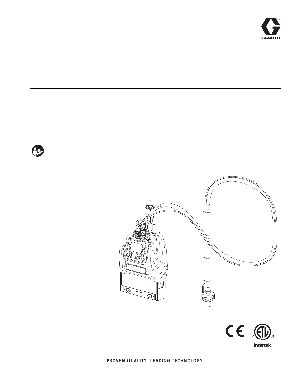
Graco InvisiPac Tank-Free HM25 Instructions - Parts Manual
Instructions - Parts
™
InvisiPac
™
HM25 Tank-Free
3A2347ZAA
Hot Melt Delivery System
For delivering and dispensing hot melt adhesive pellets. For professional use only.
Not approved for use in explosive atmospheres or hazardous locations.
1200 psi (8.3 MPa, 83 bar) Maximum Working Pressure
400°F (204°C) Maximum Fluid Operating Temperature
100 psi (0.7 MPa,7 bar) Maximum Air Inlet Pressure
Important Safety Instructions
Read all warnings and instructions in this
manual and in the gun and hose manuals.
Save all instructions.
EN
ti20440b
9902471
Certified to
CAN/CSA C22.2 No. 88
Conforms to
ANSI/UL 499

Contents
Related Manuals ...........................3
Required Tools ............................3
Models ...................................4
Warnings .................................5
Component Identification ...................8
Setup....................................13
Grounding ............................. 13
Location .............................. 13
Attach Components ..................... 13
Recommended Air Setup .................17
Connect Electrical Cord ..................18
480V Electrical Circuits ...................20
208V Electrical Circuits ...................20
SelectADMSettings ..................... 20
Guns .................................22
PLC Connection ........................23
Material Tracking ....................... 25
Operation ................................ 29
Overview ..............................29
Initial Startup and Prime .................. 29
Manual Refill ........................... 30
Automatic Refill .........................31
Dispense ..............................31
Shutdown ............................. 32
Schedule ..............................32
Pressure Relief Procedure ................33
Drain the System ....................... 33
Flush .................................34
Operation Tips to Minimize Charring.........36
Maintenance ..............................37
Replace Outlet Filter ..................... 37
Replace Inlet Filter ...................... 37
Replace Funnel Filter ....................38
Filter Maintenance Guidelines* .............39
Troubleshooting ..........................40
ADM Error Code Table ...................40
MZLP Troubleshooting ................... 53
Repair ................................... 54
Pump ................................. 54
Melter.................................58
Multi-Zone Low Power Temperature Control Module
(MZLP) ............................65
System ................................67
AirControls ............................69
AirMotor ..............................70
Software Update Procedure ...............74
Electrical Schematics ......................76
Incoming Power and Terminal Jumpers ......76
Typical Hose Applicator Wiring .............80
Parts ....................................81
Inlet Funnel Filter Kit, 24U701 ..............93
Accessories ..............................94
Preventive Maintenance Kit ................95
Complete Maintenance Kit ................95
Non-Graco Gun Adapter Cables ............96
Air Adjustment Lock, 24R084 ..............97
System Stand, 24R088 ...................98
Caster for Stand, 120302 .................98
Adapter Plate, 24R083 ...................98
30 Gallon Vibrating Hopper, 24R136 .........99
Light Tower Kit, 24R226 .................101
Air Reservoir Kit, 16W366 ................102
Air Metric Fitting Kit, 24W637 .............110
Material Tracking Kit, 24Y162 .............110
AppendixA-ADM ........................111
General Operation ......................111
Icon Identification .......................111
Appendix B - USB Downloading, Uploading . . . 117
Download Procedure ....................117
Accessing Files ........................117
Upload Procedure ......................117
USB Logs ............................118
System Settings File ....................118
System Language File ...................119
Technical Data ...........................120
Graco Extended Warranty ..................126
GracoInformation ........................126
2 3A2347ZAA

Related Manuals
Manuals are available at www.graco.com. Component
manuals in English:
Part Description
3A2805 InvisiPac GS35 Hot Melt Gun Instructions -
Parts
332072 InvisiPac Heated Hose Instructions - Parts
333348 MZLP Fuse Kit, Instructions
334784 InvisiPac Pattern Controller, Opera-
tions-Repair-Parts
335010 Dedicated Feed Sensor Air Kit
Required Tools
Related Manuals
• Standard allen wrench set
• Metric allen wrench set
• Various sizes of crescent wrenches
• 11/16 in. wrench
• 3/8 in. ratchet
• 3/8 in. socket
• 5/16 in. driver
• 7/16 in. socket
• 7/8 in. deep well socket
• 1 in. socket
• 13 mm socket
• 10 mm socket
• 1/2 in. ratchet
• Side cutter
• Phillips head screwdriver
• Flat head screwdriver
• Multimeter
• Tubing cutter
3A2347ZAA 3

Models
Models
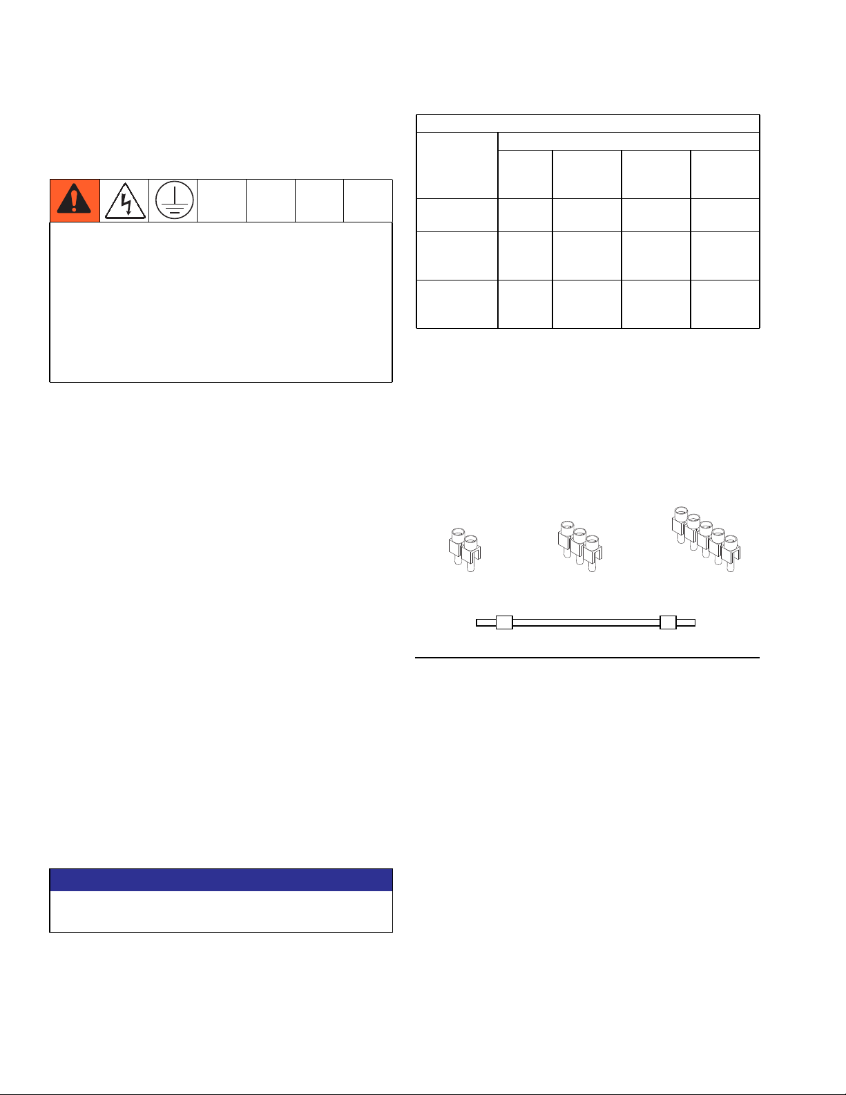
NOTICE
To prevent system damage, verify terminal jumpers
are installed correctly before applying power.
Model Channels Voltage ˓ Type Description Frequency
24P260 2 200-240VAC
24P261 4 200-240VAC
24P262 2 350-415VAC Y
24P263 4 350-415VAC Y
24P264 2
24P265 4
24U132 6 200-240VAC
24U133 6 350-415VAC Y
24U134 6
200-240VAC ˂
200-240VAC ˂
200-240VAC ˂
1˓ /PE
1˓ /PE
3˓ / Neutral / PE
3˓ / Neutral / PE
3˓ /PE
3˓ /PE
1˓ /PE
3˓ / Neutral / PE
3˓ /PE
• 1-Phase
• 200-240VAC
• 2 wire and PE
• 3-Phase with Neutral
• 350-415 VAC Line to
Line
• 200-240VAC Line to
Neutral
• 3 wire and Neutral and
PE
• 3-Phase without
Neutral
• 200-240 VAC Line to
Line
• 3 wire and PE
• 1-Phase
• 200-240VAC
• 2 wire and PE
• 3-Phase with Neutral
• 350-415 VAC Line to
Line
• 200-240VAC Line to
Neutral
• 3 wire and Neutral and
PE
• 3-Phase without
Neutral
• 200-240 VAC Line to
Line
• 3 wire and PE
50/60 Hz 32A
50/60 Hz 40A
50/60 Hz 16A
50/60 Hz 16A
50/60 Hz 27A
50/60 Hz 27A
50/60 Hz 40A
50/60 Hz 30A
50/60 Hz 40A
Max
Amps
4 3A2347ZAA
Warnings
Warnings
The following warnings are for the setup, use, grounding, maintenance, and repair of this equipment. The exclamation point symbol alerts you to a general warning and the hazard symbols refer to procedure-specific risks. When
these symbols appear in the body of this manual or on warning labels, refer back to these Warnings. Product-specific
hazard symbols and warnings not covered in this section may appear throughout the body of this manual where
applicable.
WARNING
ELECTRIC SHOCK HAZARD
This equipment must be grounded. Improper grounding, setup, or usage of the system can cause
electric shock.
• Turn off and disconnect power at main switch before disconnecting any cables and before servicing
or installing equipment.
• Connect only to grounded power source.
• All electrical wiring must be done by a qualified electrician and comply with all local codes and
regulations.
BURN HAZARD
Equipment surfaces and fluid that’s heated can become very hot during operation. To avoid severe
burns:
• Do not touch hot fluid or equipment.
SKIN INJECTION HAZARD
High-pressure fluid from dispensing device, hose leaks, or ruptured components will pierce skin. This
may look like just a cut, but it is a serious injury that can result in amputation. Get immediate surgical
treatment.
+
• Do not point dispensing device at anyone or at any part of the body.
• Do not put your hand over the fluid outlet.
• Do not stop or deflect leaks with your hand, body, glove, or rag.
• Follow the Pressure Relief Procedure when you stop dispensing and before cleaning, checking, or
servicing equipment.
• Tighten all fluid connections before operating the equipment.
• Check hoses and couplings daily. Replace worn or damaged parts immediately.
MOVING PARTS HAZARD
Moving parts can pinch, cut or amputate fingers and other body parts.
• Keep clear of moving parts.
• Do not operate equipment with protective guards or covers removed.
• Pressurized equipment can start without warning. Before checking, moving, or servicing equipment,
follow the Pressure Relief Procedure and disconnect all power sources.
3A2347ZAA 5
Warnings
WARNING
EQUIPMENT MISUSE HAZARD
Misuse can cause death or serious injury.
• Do not operate the unit when fatigued or under the influence of drugs or alcohol.
• Do not exceed the maximum working pressure or temperature rating of the lowest rated system
component. See Technical Data in all equipment manuals.
• Use fluids and solvents that are compatible with equipment wetted parts. See Technical Data in all
equipment manuals. Read fluid and solvent manufacturer’s warnings. For complete information
about your material, request MSDS from distributor or retailer.
• Do not leave the work area while equipment is energized or under pressure.
• Turn off all equipment and follow the Pressure Relief Procedure when equipment is not in use.
• Check equipment daily. Repair or replace worn or damaged parts immediately with genuine manufacturer’s replacement parts only.
• Do not alter or modify equipment. Alterations or modifications may void agency approvals and create
safety hazards.
• Make sure all equipment is rated and approved for the environment in which you are using it.
• Use equipment only for its intended purpose. Call your distributor for information.
• Route hoses and cables away from traffic areas, sharp edges, moving parts, and hot surfaces.
• Do not kink or over bend hoses or use hoses to pull equipment.
• Keep children and animals away from work area.
• Comply with all applicable safety regulations.
FIRE AND EXPLOSION HAZARD
Flammable fumes, such as solvent and paint fumes, in work area can ignite or explode. To help prevent
fire and explosion:
• Do not use solvent-based adhesives that can create an explosive atmosphere when processed.
• Use equipment only in well ventilated area.
• Eliminate all ignition sources; such as pilot lights, cigarettes, portable electric lamps, and plastic drop
cloths (potential static arc).
• Keep work area free of debris, including solvent, rags and gasoline.
• Do not plug or unplug power cords, or turn power or light switches on or off when flammable fumes
are present.
• Ground all equipment in the work area. See Grounding instructions.
• Use only grounded hoses.
• Stop operation immediately if static sparking occurs or you feel a shock. Do not use equipment
until you identify and correct the problem.
• Keep a working fire extinguisher in the work area.
TOXIC FLUID OR FUMES HAZARD
Toxic fluids or fumes can cause serious injury or death if splashed in the eyes or on skin, inhaled, or
swallowed.
• Read MSDSs to know the specific hazards of the fluids you are using.
• Store hazardous fluid in approved containers, and dispose of it according to applicable guidelines.
6 3A2347ZAA
Warnings
WARNING
PERSONAL PROTECTIVE EQUIPMENT
Wear appropriate protective equipment when in the work area to help prevent serious injury, including
eye injury, hearing loss, inhalation of toxic fumes, and burns. This protective equipment includes but is
not limited to:
• Protective eyewear, and hearing protection.
• Respirators, protective clothing, and gloves as recommended by the fluid and solvent manufacturer
PRESSURIZED ALUMINUM PARTS HAZARD
Use of fluids that are incompatible with aluminum in pressurized equipment can cause serious chemical
reaction and equipment rupture. Failure to follow this warning can result in death, serious injury, or property damage.
• Do not use 1,1,1-trichloroethane, methylene chloride, other halogenated hydrocarbon solvents or
fluids containing such solvents.
• Many other fluids may contain chemicals that can react with aluminum. Contact your material supplier for compatibility.
3A2347ZAA 7
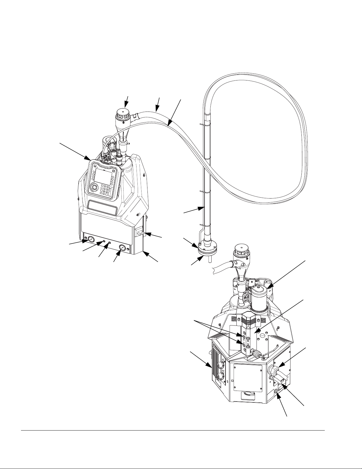
Component Identification
Component Identification
G3
G2
G4
A
G
G1
H
F
E
C
D
B
K
L
Key:
A Advanced Display Module (ADM)
B Electrical Enclosure
C Pump Air Pressure Regulator
D Pump Air Pressure Gauge
E Vacuum Transfer Air Pressure Regulator
F Vacuum Transfer Air Pressure Gauge
G Shaker Tube
G1 Shaker Head
G2 Vacuum Transfer Tube
G3 Vacuum Transfer Inlet Funnel
G4 Vacuum Transfer 3/8 in. OD Air Supply
H Main Power Switch
J System Air Inlet
K Vacuum Transfer (Shaker) Inlet
L Air Motor and Pump
M Incoming Power Strain Relief
N Heated Fluid Manifold (Melter)
P Multi-Zone Low Power Temperature Control Module (MZLP)
R Fluid Outlets for connection to Heated Hoses (numbered 1-4)
S Customer I/O Cable (optional)
R
P
ti20441b
N
M
S
J
FIG.1
8 3A2347ZAA
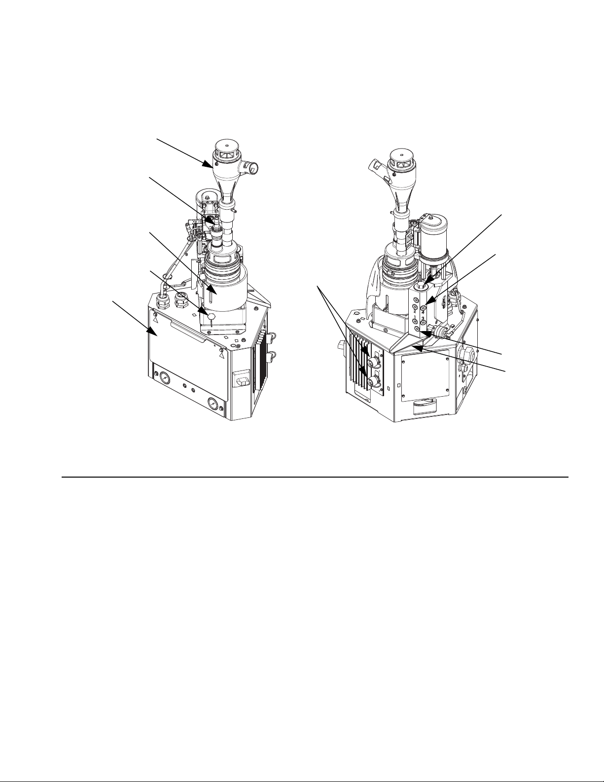
Heated Fluid Manifold
AB
Z
U
X
T
Component Identification
Y
R
AA
NOTE: System shown with plastic and metal shrouds removed.
FIG.2
Key:
T Electrical Enclosure Front Access Door
U Melter
W1 Drain Port
W2 Drain Tray
X Inlet Filter (Low Pressure - Before Pump)
Y Outlet Filter (High Pressure - After Pump)
W1
W2
ti20442b
Z Adhesive Pellets Level Sensor
AA Power and RTD Harness Connection to Heated Hose and
Gun (harness connects from system to heated hose then
from heated hose to gun)
AB Inlet Funnel Screen
3A2347ZAA 9
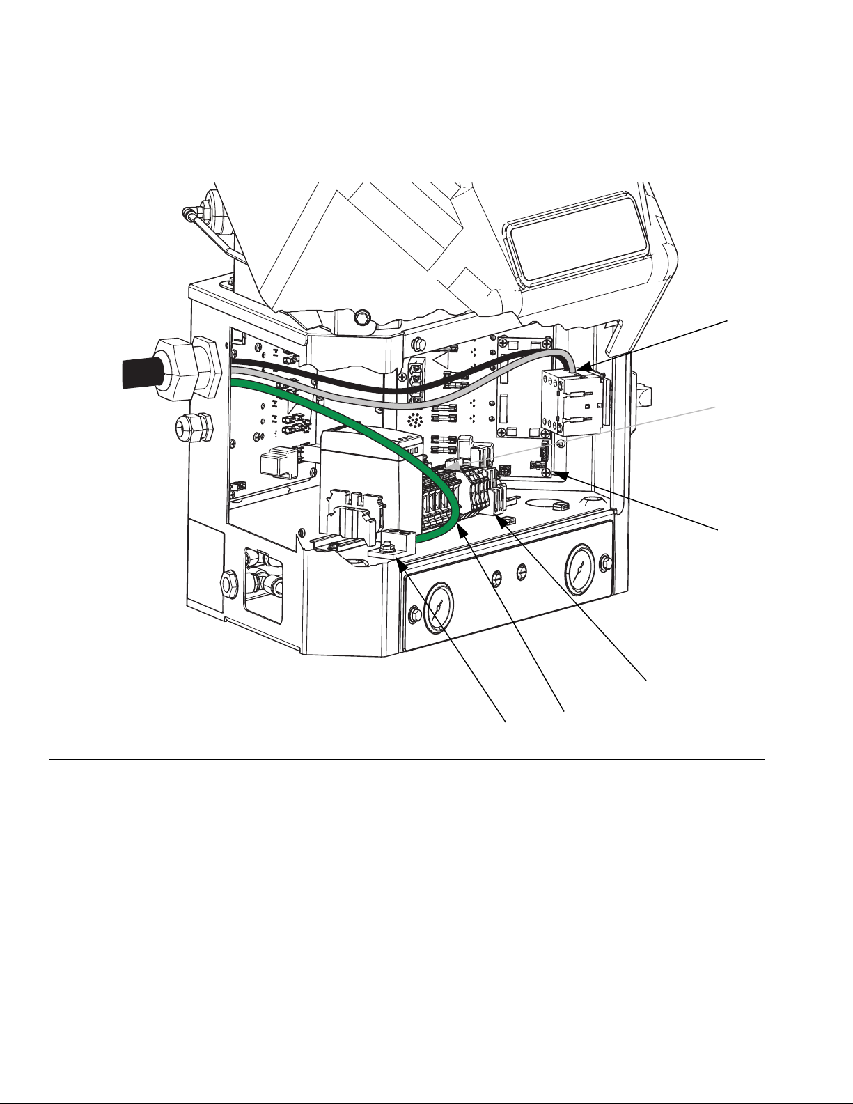
Component Identification
Electrical Enclosure
AC
AJ
FIG.3
Key:
P Multi-Zone Low Power Temperature Control Module
(MZLP)
AC Incoming Power Connection
AF Chassis Ground
P
ti20907b
AH
AG
AF
AG Terminal Blocks and Jumpers
AH Heater Relay
AJ Incoming Power Terminal Jumpers. See page 18.
10 3A2347ZAA
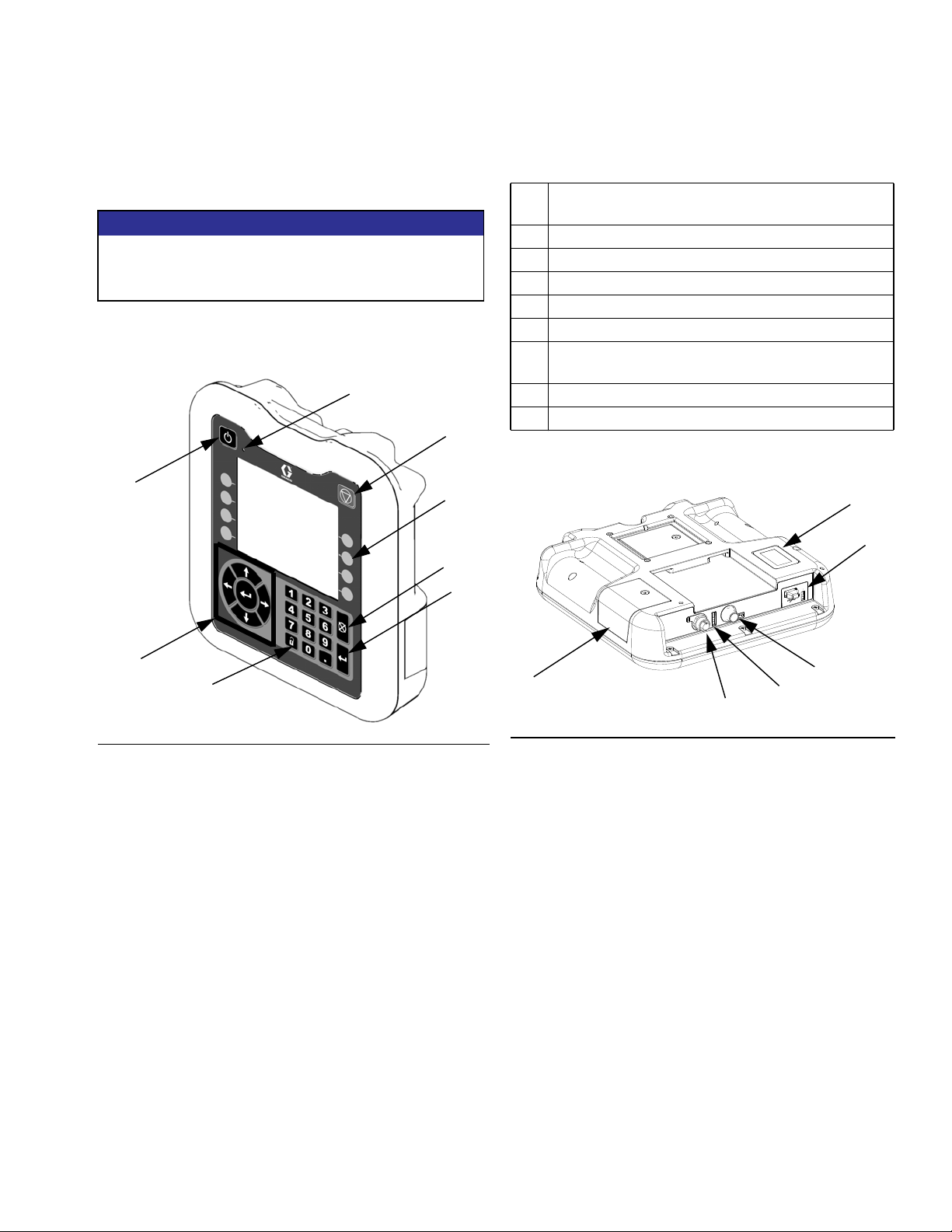
Advanced Display Module (ADM)
Component Identification
User Interface
NOTICE
To prevent damage to soft key buttons, do not press
the buttons with sharp objects such as pens, plastic
cards, or fingernails.
NOTE: See AppendixA-ADMon page 111 for complete ADM operation details.
BB
BC
BA
BD
BE
BF
B
Ke
y Function
BA Heating system and pump enable/disable
BB System status indicator (LED)
BC Stop all system processes
BD Defined by icon next to softkey
BE Abort current operation
BF Accept change, acknowledge error, select item,
toggle selected item
BG Toggle between Operation and Setup screens
BH Navigate within a screen or to a new screen
BK
BL
BH
FIG.4
BG
TI12362a1
BR
BM
BN
BP
FIG.5
Key:
BK Part Number Identification Label
BL USB Interface
BM CAN Cable Connection (Power Supply and Communica-
tion)
BN Module Status LEDs
BP (Not used)
BR Software Token Access Panel
3A2347ZAA 11
Component Identification
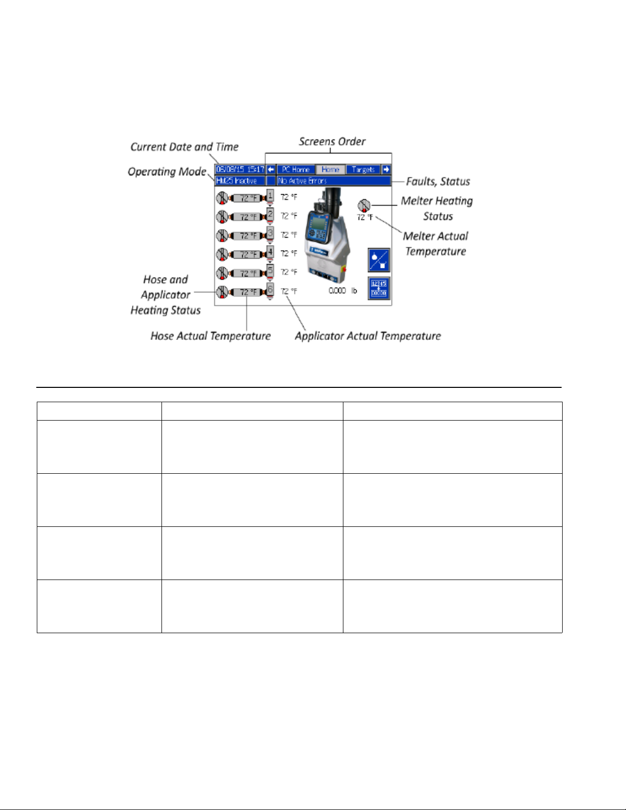
Screen Components
FIG. 6: Main Screen Components
Operating Mode Description Component Status
• No System Status Indicator LED on the
System Off
Inactive
Warm Up
Active
The system doesn’t have power.
The heating system and pumps are
disabled.
The system is increasing the material
to the set temperature.
The system is ready to dispense
material.
ADM
• No heat
• Pump is off
• Yellow system status indicator LED on the
ADM
• No heat
• Pump is off (manually changed)
• Flashing green system status indicator LED
on the ADM
• Heat is increasing to setpoint temperature
• Pump is off
• Solid green system status indicator LED on
the ADM
• Heat is at setpoint temperature
• Pump is on
12 3A2347ZAA

Setup
Setup
Grounding
The equipment must be grounded to reduce the risk
of electric shock. Improper grounding can cause
electric shock. Grounding provides an escape wire
for the electric current.
The InvisiPac system is equipped with a ground terminal. Have a qualified electrician ground the system
using this terminal. See Connect Electrical Cord on
page 18.
Location
Ambient temperature must be 32-120°F (0-49°C).
The supplied vacuum transfer hose length is 10 ft (3 m).
The maximum vacuum transfer hose length available is
30 ft (9.1 m). The adhesive pellets container must be
located within reach of the vacuum transfer hose and no
more than 30 ft (9.1 m).
The gun(s) must be located no more than 25 ft (7.6 m)
from the melter.
Place the base system on a surface that is eye-level for
easiest operation. Use System Stand, 24R088,to
install system at eye-level. See page 98.
If installing the system in place of a non-Graco hot melt
system, purchase Adapter Plate, 24R083. See
page 98.
Attach Components
To reduce the risk of electric shock, do not connect
electrical cord until after this Attach Components
procedure is complete.
1. Place the base system in the desired operating
location and orientation. See Location on this page.
• The bottom of the electrical enclosure has holes for
securing the InvisiPac system to a surface. The
holes are accessible through the bottom access
doors in the three rear walls of the electrical enclosure.
• To install the InvisiPac system in place of a
non-Graco hot melt system, purchase Adapter
Plate, 24R083. See installation instructions on
page 98.
• To raise the system to eye-level, purchase System
Stand, 24R088. See installation instructions on
page 98.
NOTE: Supplied vacuum transfer hose must reach from
the system to the adhesive pellets container. Supplied
heated hose must reach from system to gun(s).
2. Install vacuum transfer inlet funnel (G3) onto system. See FIG.7.
a. Slide funnel through the bracket connected to
the air motor.
Optional 30 Gallon Vibrating Hopper, 24R136, available (purchase separately). See page 99.
To make repairing the system easier, locate the system
so that all sides are easily accessible and have sufficient
lighting.
3A2347ZAA 13
b. Position the funnel so the funnel inlet faces the
desired direction.
c. Connect 5/32 in. OD air line to funnel.
d. Install supplied hose clamp around the air motor
bracket and funnel base then tighten.
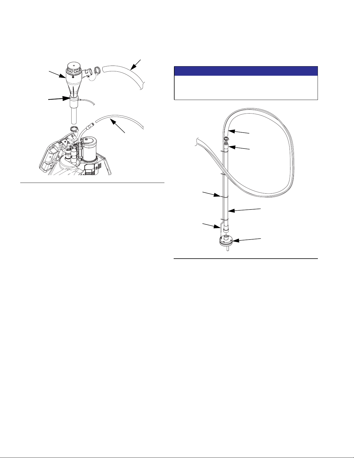
Setup
G2
6. Apply pipe sealant to threads then attach steel
shaker tube (G) to shaker head (G1). See FIG.8.
G3
G7
G4
ti21130b
FIG.7
3. Insert 1.3 in. (33 mm) OD clear vacuum transfer
hose (G2) into vacuum transfer funnel (G3) inlet and
secure with supplied hose clamp. See FIG.7.
4. Connect the long supplied 3/8 in. OD air line (G4) to
the 3/8 in. push-to-connect fitting on the air line from
the system. See FIG.7.
NOTE: To rotate funnel, loosen set screws (qty 4, G7)
1/4 turn each. Once funnel is aligned properly, hand
tighten screws back down.
NOTICE
To prevent shaker head (G1) galling to the shaker
tube (G), do not overtighten shaker head onto shaker
tube. These should be hand-tightened.
G2
G6
G5
G
G4
G1
ti21131a
FIG.8
NOTE: In the following steps, when routing the vacuum
transfer hose, ensure there are no tight coils, turns, or
dips in the vacuum hose. These will inhibit optimal functioning of the vacuum transfer system.
NOTE: Maximum vacuum hose length is 30 ft (9.1 m).
Use horizontal hose routing as much as possible. The
vacuum hose must not rise more than 10 ft (3.0 m),
measured from the vacuum inlet. Any vertical rise will
lower the maximum flow rate of the vacuum transfer
system.
5. Route the 1.3 in. (33 mm) OD clear vacuum transfer
hose from the system to the adhesive pellets container location.
7. Attach 1.3 in. (33 mm) clear vacuum transfer hose
(G2) to steel shaker tube (G) and secure with supplied hose clamp. See FIG.8.
8. Route the 3/8 in. OD air line (G4) alongside the
1.3 in. (33 mm) clear vacuum transfer hose (G2)
and secure at multiple points with the supplied zip
ties (G5). See FIG.8.
9. If desired, secure the 1.3 in. (33 mm) clear vacuum
transfer tube and 3/8 in. OD air line with zip ties to a
supporting structure at various points in the routing.
10. Attach the other end of the long 3/8 in. OD air line
(G4) to the 3/8 in. push-to-connect fitting on the
shaker head (G1).
11. Ensure the adhesive pellets container is in the
desired operating location. The location should be
chosen to make it easy to fill the container with pellets.
14 3A2347ZAA
Setup
12. Place shaker assembly in an empty adhesive pellets container then fill the container with adhesive
pellets.
NOTE: To promote optimal system performance, purchase 30 Gallon Vibrating Hopper, 24R136. See
installation instructions on page 99.
NOTE: If static buildup on feed tube (G) is excessive,
install optional feed tube ground kit 24R708 to feed tube
end (G6). See FIG.8.
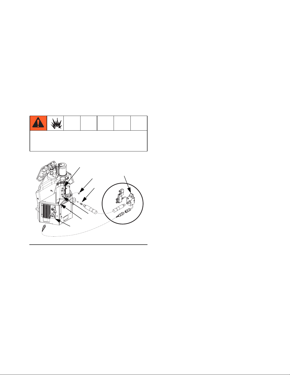
13. Install heated hoses, see FIG.9:
To reduce the risk of fire and explosion, only use
Graco heated hoses with the InvisiPac system. Use
of non-Graco hoses will void agency approvals.
N
247
Gun
68
d. Remove plug (247) from the lowest numbered
outlet on the melter. Do not use the drain
plug (W1). See FIG.9.
NOTE: In the following step, the o-ring side of the
hydraulic fitting (68) faces the system. See FIG.9.
e. Install the supplied hydraulic fitting (68) with an
o-ring into the open port and tighten with an
11/16 in. wrench or socket.
f. Install hose onto hydraulic fitting (68) with male
electrical connector side toward the system.
Use 11/16 in. wrench to tighten hose onto
hydraulic fitting (68).
g. Locate MZLP (AA) connector marked with same
number as the hose fluid outlet port. Remove
that connector cover then install connector from
heated hose. See FIG.9.
h. Repeat the procedure for the remaining chan-
nels. Use the bottom melter ports first to ease
installation.
W1
W2
AA
ti21132a
FIG.9
a. Place a rag on the drain tray (W2) attached to
the melter. Residual oil may be in the system
from the factory. See FIG.9.
b. Use a 1/4 in. allen wrench to remove the drain
port plug (W1). See FIG.9.
NOTE: A 1/4 in. allen wrench is shipped loose with the
system.
c. When fluid stops draining, re-install drain port
plug (W1) then remove rag. See FIG.9.
i. Install cap on any unused MZLP electrical con-
nectors.
NOTE: Fluid outlet port 1 must be used and electrical
connector from that hose must be connected to MZLP
connector 1. The system will not operate unless a hose
is connected to MZLP connector 1. If a hose is not connected to connector 1, “Invalid Sensor - hose/gun” faults
will result.
14. Install gun(s), see FIG.9:
NOTE: Use of a Graco gun is not required with this system. However, all guns attached to the system must be
rated for 1200 psi (8.3 MPa, 83 bar), 400°F (204°C),
have an RTD type sensor, and use no more than 400W.
a. Connect heated hose fluid outlet to gun fluid
inlet. Use 11/16 in. wrench to tighten. See FIG.
9.
b. For Graco guns, attach gun electrical connector
to heated hose electrical connector. See FIG.9.
3A2347ZAA 15

Setup
c. For non-Graco guns, attach gun electrical con-
nector to adapter harness (16T916, 16T917, or
16Y828) then attach adapter harness connector
to heated hose connector. See Non-Graco
Gun Adapter Cables on page 96 to determine
which adapter cable to use with your valve.
d. Repeat for any additional guns.
15. If necessary, set up the valve controller to control
opening and close the gun. See gun manual.
NOTE: The system controls gun heating only. A separate gun controller must be set up to open and close the
guns.
16. Install the supplied air inlet bleeding ball valve and
air filter kit (Graco Part No. 24R707) at the 1/4 NPT
female system air inlet (J). See FIG.10.
17. If using the same air for the gun(s), make sure to
install the tee in the air line before the ball valve.
There should not be anything between the ball valve
and the system. See gun manual for gun air pressure requirements, and use a regulator before the
gun to decrease the air pressure, if necessary.
18. Close the ball valve.
WLE
ti21147a
FIG.11
19. Attach a 3/8 in. minimum air supply line to air filter.
See FIG.11.
J
WLE
ti21133a
FIG.10
NOTE: The system must have a bleed-type ball valve
that bleeds pressure downstream when closed. Otherwise, the supplied air will need to be disconnected from
the system whenever the pressure is relieved.
NOTE: The system must use an air filter with a minimum flow rate of 30 scfm.
NOTE: Air supply pressure must be between 80 psi
(550 kPa, 5.5 bar) and 100 psi (690 kPa, 6.9 bar). Recommended pressure is 100 psi (690 kPa, 6.9 bar). If air
pressure is expected to drop below 80 psi (0.5 MPa,
5 bar), there is an air reservoir kit that allows the system
to operate down to 60 psi (0.4 MPa, 4 bar). See Air
Reservoir Kit, 16W366, on page 102.
20. To lock access to the air pressure adjustments, purchase See Attach Components on page 13.. See
installation instructions on page 96.
21. To install a light tower that illuminates red when a
system error occurs, purchase Light Tower Kit,
24R226. See installation instructions on page 101.
22. To upgrade a 2 channel system to a 4 channel system, purchase 4 Channel Upgrade Kit, 24R237.
See installation instructions on page 103.
23. Install MZLP electrical connector caps on all unused
channels.
16 3A2347ZAA
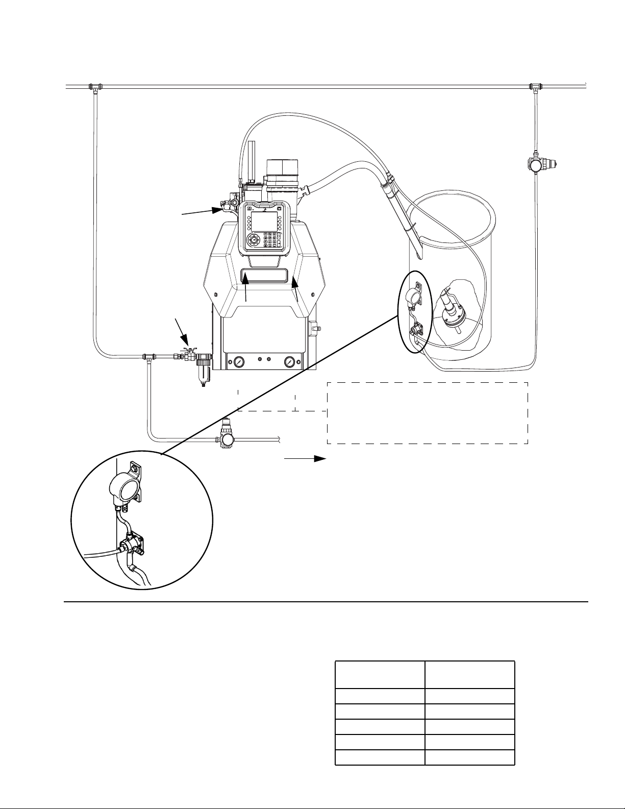
Recommended Air Setup
Main Air Line
Setup
Air In:
Less than 50 ft (15.2 m): 3/8 in.
More than 50 ft (15.2 m): 1/2 in.
80-100 psi
(5.5-6.8 bar, 0.55-6.8 MPa)
30 scfm capacity.
Ensure funnel air
is connected
Air Filter/Ball Valve at
System Air Inlet
(Graco Kit 24R707,
included)
Vacuum Pump
No dips in vacuum
transfer hose
40 - 80 psi (2.8-5.5 bar,
0.28-0.55 MPa);
Air In:
3/8 in.,
100 psi
(6.8 bar, 0.68 MPa),
30 scfm capacity
Regulator
Vacuum:
Pump:
20-100 psi
Regulator set to
70 psi
(4.8 bar, 0.48 MPa)
InvisiPac
Vacuum
Feed Air
Hopper
Shaker
Pilot
Valve
Plant Air
Supply
FIG.12
If plant air pressure is >90 psi, add air regulator kit to the
24H420 to the air supplying the hopper shaker. Regulate the shaker air according to the vacuum feed pressure according to the table below.
WLF
Air to applicators
NOTE: Using vacuum feed air pressure higher than
necessary may cause the melter to over fill and Interrupt
production.
Vacuum Feed air
pressure
Max air pressure
to hopper
40 psi (2.8 bar) 60 psi (4.1 bar)
50 psi (6.4 bar) 75 psi (5.2 bar)
60 psi (4.1 bar) 90 psi (6.2 bar)
70 psi (4.8 bar) 105 psi (7.2 bar)
80 psi (5.5 bar) 120 psi (8.3 bar)
3A2347ZAA 17
Setup
Connect Electrical Cord
NOTE: See Grounding section on page 13.
Improper wiring may cause electric shock or other
serious injury if work is not performed properly. Have
a qualified electrician perform any electrical work. Be
sure your installation complies with all National, State
and Local safety and fire codes.
To reduce the risk of electric shock, perform the
entire Attach Components procedure beginning on
page 13 prior to connecting electrical cord.
NOTE: The installed strain relief bushing (106) fits a
0.708-1.260 in. OD electrical cord. See FIG.14.If
needed, use a wrench to tighten the strain relief bushing
until it is snug on the cable.
NOTE: Tubing 17F777 and 17F779 is included for
smaller diameter electrical cord. Place around the power
cord and secure in the strain relief brushing (106).
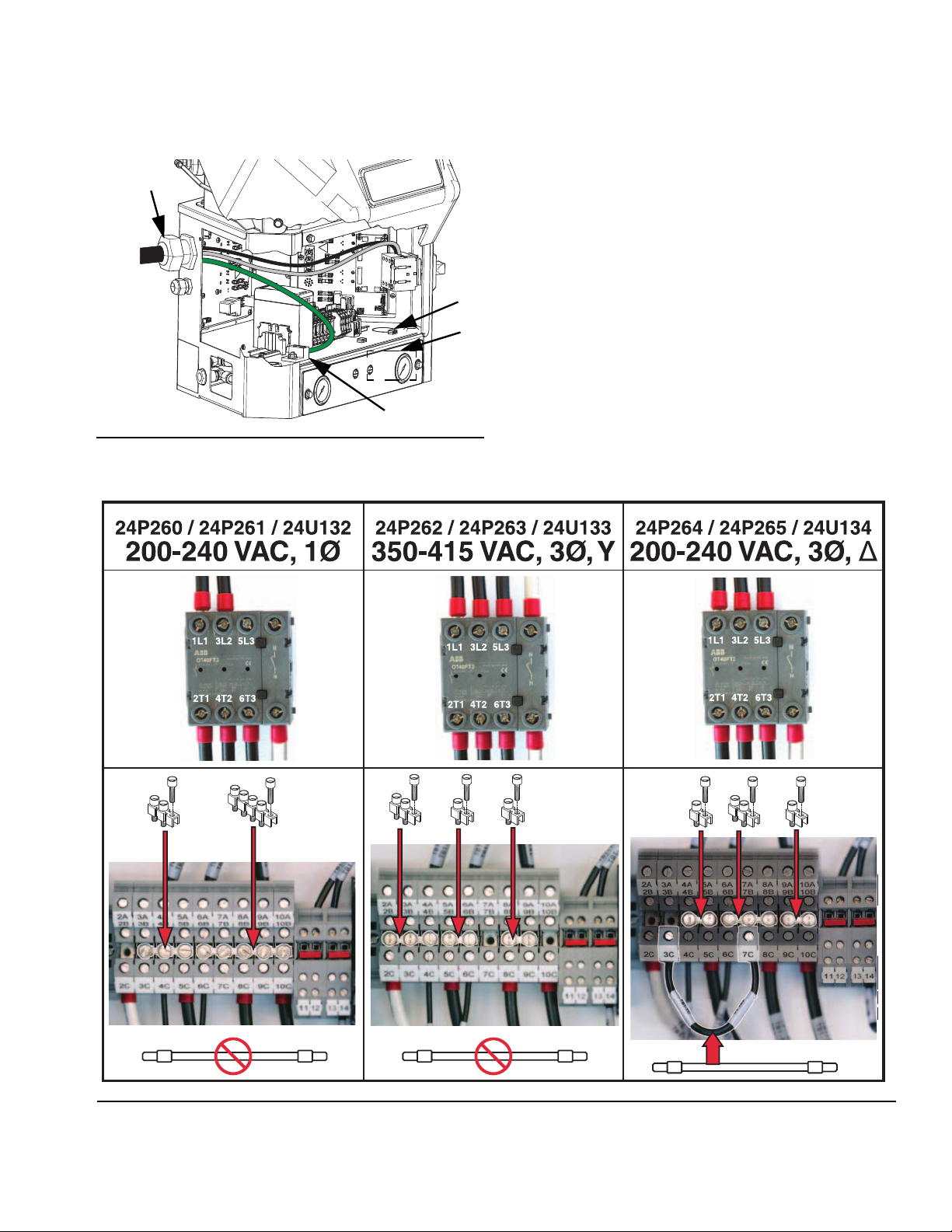
Terminal Block Jumper Installation Guide
Terminal Block Location
Voltage
200-240VAC,
1 phase
350-415VAC,
3 phase,
WYE
200-240VAC,
3 phase,
DELTA
Jumper
Wire
127201
Not used Not used 3-5 6-10
Not used
3-7
2-Terminal
Jumper
126814
5-6,
8-9
4-5,
9-10
3-Terminal
Jumper
126815
2-4 Not used
6-8 Not used
5-Terminal
Jumper
126816
NOTE: The jumpers only need to be changed if using a
different phase or voltage from what the system was
designed for at the factory.
NOTE: All necessary jumpers are supplied with the system in a bag located behind the electrical enclosure
front access panel. Keep unused jumpers in bag.
2-Terminal
126814
3-Terminal
126815
5-Terminal
126816
NOTE: The accessory strain relief bushing kit 24x190 is
available for smaller (0.512-1.024 in, 13-26 mm) OD
electrical cords. See Accessories, page 107.
For 480V Electrical Circuits, see page 20.
1. Turn main power switch OFF.
2. Disconnect cable from ADM, push cable through
plastic shroud, then remove plastic shroud from system.
3. Remove electrical enclosure access door (T). See
FIG. 2 on page 9.
4. Ensure the terminal block jumpers are in the correct
locations for the phase and voltage used. If necessary, change them to match FIG. 15 on page 19.
See the following table, FIG. 13, and FIG.15.
NOTICE
To prevent system damage, verify terminal jumpers are
installed correctly before going on to the next step.
ti21182a
Wire
127201
FIG. 13: Jumpers
NOTE: Use the supplied hard metal 2, 3, and 5 terminal
jumpers and jumper wire for terminals 2C-10C. Use the
red, plastic jumpers for terminals 11-14.
5. Insert electrical cord through electrical enclosure
strain relief bushing (106). See FIG. 14 on page 19.
a. Alternate electrical cord routing: using conduit,
run electrical cord from access port (X) through
hole (Y). Conduit is required when routing wires
near compressed air components.
18 3A2347ZAA
Setup
6. Attach insulated ferrules to the end of each wire. 7. Connect ground wire to chassis ground (AF). See
FIG.14.
106
8. Connect L1, L2, L3, and N as shown in FIG. 15. Not
all models use all 4 wires.
9. Use zip ties to secure the electrical cord to the
tie-downs located on the top of the inside of the
electrical enclosure.
Y
X
10. Tighten screw-terminals to at least 10 in-lb
(1.1 N•m).
11. Install electrical enclosure door.
FIG.14
AF
ti20907b
12. Perform Select ADM Settings on page 20 prior to
turning on heat.
FIG.15
3A2347ZAA 19
Setup
480V Electrical Circuits
For 480V electrical supply, a 480V to 240V step-down
transformer must be installed by a qualified electrician.
Transformer Sizing
For single-phase power, 480V to 240V transformer
24U169 (purchase separately) may be used. See Sin-
gle-Phase 480V to 240V Transformer, 24U169 on
page 107.
Minimum transformer rating can be calculated by taking
output voltage times the ADM setting.
Single Phase, 20A ADM Breaker Setting Example:
240 volts x 20 amps = 4800 watts
Three Phase, 20A ADM Breaker Setting Example:
240 volts x 20 amps x ෭ (3) = 8315 watts
208V Electrical Circuits
For 208V electrical supply, a qualified electrician can
install a 208V to 240V step-up transformer to improve
startup times.
Transformer Sizing
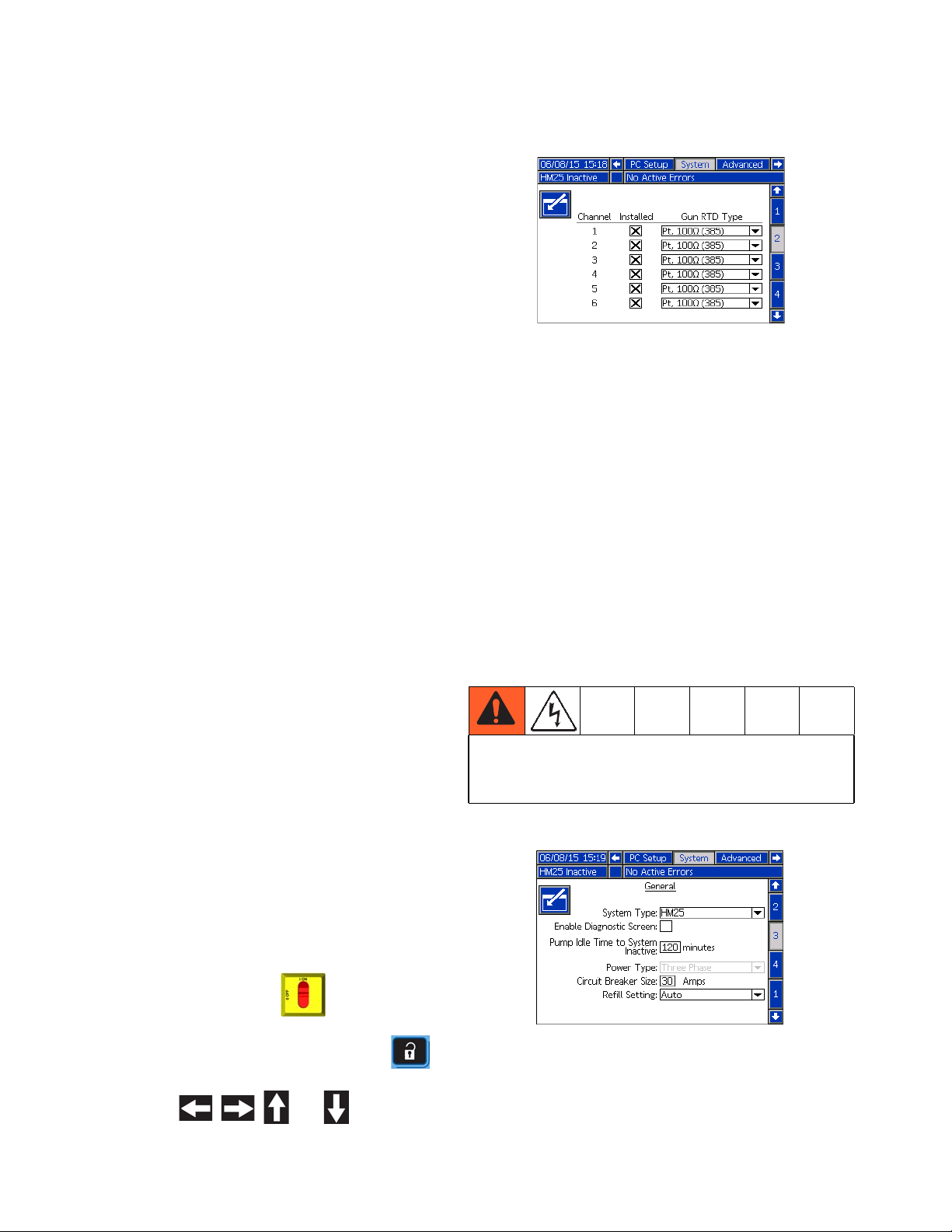
3. On the System 2 screen:
a. Check the box in the “Installed” column for each
channel that has a heated hose and gun
installed.
b. Select the RTD type used on each installed
gun. See gun manual.
NOTE: An incorrect RTD setting will cause the system
to be incapable of maintaining the temperature setting.
NOTE: The supported RTD types are Ni, 100 ohm; Ni,
120 ohm; NiFe, 604 ohm; Pt, 100 ohm (385), Pt,
100 ohm (392); and Pt, 1000 ohm. An “Auto” selection is
available but should only be used when the specific
RTD type cannot be identified. Using the “Auto” RTD
setting may result in inaccurate temperatures.
Minimum transformer rating can be calculated by taking
transformer output voltage times the ADM breaker setting.
Single Phase, 20A ADM Breaker Setting Example:
240 volts x 20 amps = 4800 watts
Three Phase, 20A ADM Breaker Setting Example:
240 volts x 20 amps x SQRT(3) = 8315 watts
Select ADM Settings
NOTE: See AppendixA-ADMon page 111 for
detailed ADM information, including general operation.
1. Turn main power switch ON .
2. When the ADM is finished starting up, press
to switch from the Operation screens to the Setup
screens. Use , , , and to navigate
between screens.
To prevent fire and explosion, a qualified electrician
must determine the proper circuit breaker size to use
for the power supplied to the system.
4. On the System 3 screen:
a. Enter the main circuit breaker size used. This is
the circuit breaker installed external to the system for the system power supply.
20 3A2347ZAA
Setup
NOTE: If using a 480V to 240V transformer, the breaker
size entered will be two times the 480V rating. If using
transformer 24U169, the breaker size should be set to
30 amps and power type should be set to single phase.
NOTE: The InvisiPac system limits the amount of power
it pulls based on the input circuit breaker size. This
impacts the startup times because it affects the heating
energy used to warm up the materials.
b. Select the incoming power type.
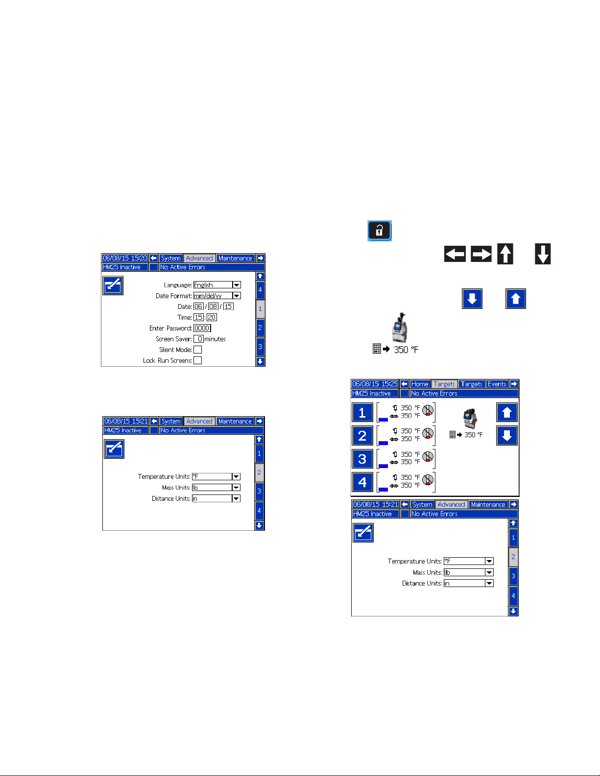
5. On the Advanced 1 screen, set the system date and
time.
NOTE: The Schedule function enables the system to
automatically enable and disable heating at specified
times so that the system is already up to temperature
when a shift begins.
8. If desired, set any remaining settings in the Setup
screens before going on to the next steps that use
the Operation screens. These are not required for
system operation but include useful functions. See
AppendixA-ADM, beginning on page 111, for
detailed information about each setup item.
9. Press to switch from the Setup screens to the
Operation screens. Use , , , and to
navigate between screens.
10. On the Targets screen, use and , shown
next to , to adjust system melter setting.
Also, the desired temperature setting can be typed
in using the numeric keypad.
6. On the Advanced 2 screen, set the temperature and
mass units.
7. To setup the optional Schedule function, see
Schedule on page 32.
3A2347ZAA 21

Setup
11. On the Targets screen, adjust heated hose and gun
temperature settings:
NOTE: InvisiPac is a high powered tank-free system
that delivers heat faster than traditional tank systems.
Tanks are often run at a lower temperature than the
application temperature to avoid excessive adhesive
degradation since a large volume of adhesive sits at
temperature.
a. Press to select the channel.
b. Use and , shown next to , to
adjust gun temperature setting to the desired
setting for that channel.
NOTE: If a higher applicator temperature is desired,
adjust all zones to the higher temperature or adjust only
the applicator in small increments.
c. Use and , shown next to ,
to adjust heated hose temperature setting to the
desired setting for that channel.
NOTE: Alternatively, use the physical up and down
arrow push-buttons on the ADM keypad until is
next to the temperature setting to change then use the
numeric keypad to enter the desired temperature.
NOTICE
Set melter, hose, and gun to the same setpoint temperature for best performance. Do not set the hose
temperature higher than the melter. Running the hose
at a setpoint higher than the melter is unnecessary in
this tank-free system and could lead to adhesive degradation in the hose. Short adhesive residence time in
the melter eliminates the need to set the melter at a
lower setpoint than other zones. See Operation Tips
to Minimize Charring, page 36.
NOTE: Alternatively, use the physical up and down
arrow push-buttons on the ADM keypad until is
next to the temperature setting to change then use the
numeric keypad to enter the desired temperature.
Guns
Gun heating is controlled by the InvisiPac system. A
pattern controller is required to control the opening and
closing of guns. If using an InvisiPac Pattern Controller,
refer to manual 334784 - InvisiPac Pattern Controller for
details on wiring and setup.
22 3A2347ZAA
Setup
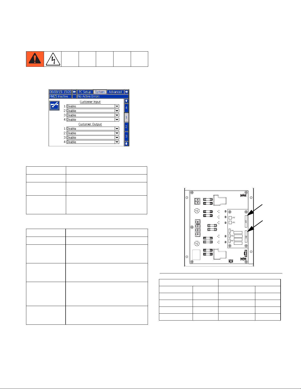
PLC Connection
A PLC can control and monitor all items shown in the
dropdown menus on the System 1 screen in the Setup
screens.
Customer Input Dropdown Options
Option Description
Disable Not used.
Heater On/Off Turn on or off the heating system and
pump.
Channel 1, 2, 3,
or 4 Enable/Disable
Customer Output Dropdown Options
Enable or disable hose and gun heating for that individual channel.
NOTE: The InvisiPac system ships with two
screw-terminal connectors that plug into MZLP
connectors H1 and H2. Connectors are located in a bag
on the inside of the electrical enclosure front access
door. To replace the connectors, order kit 24P176.
1. On the System 1 screen (in the Setup screens) select
the function of each input on MZLP connector H1 and
each output on MZLP connector H2.
2. Turn main power switch OFF.
3. Remove electrical enclosure front access door.
4. Route I/O cable through strain relief in electrical
enclosure. See Customer I/O Cable (S) in FIG.1on
page 8.
5. Remove power from PLC.
6. Connect the PLC to connectors H1 and H2.
NOTE: Each connector has four signals. The MZLP
board specifies the input range for each signal. See the
following table for pin assignments.
J1
J2
F1
F2
F3
F4
F5
J3
H1
H2
Option Description
Disable Not used.
System Ready Indicates when the system is up to tem-
perature and the pump is stalled at
pressure.
Error (Alarm) Indicates when there is an active alarm.
An active alarm will disable the heating
system and pump.
Error (Deviation/Advisory)
Maintenance Due Indicates when the maintenance total
Indicates when there is an active deviation or advisory. An active deviation or
advisory will NOT disable the heating
system and pump.
has reached the preset notification
value.
FIG. 16: MZLP Board
H1 - Customer Input H2 - Customer Output
Signal Pin Signal Pin
1 1,2 1 1,2
2 3,4 2 3,4
3 5,6 3 5,6
4 7,8 4 7,8
F7
F8
F9
F10
F6
J5
J6
J7
Inputs: High: 10-30 Vdc, Low: 0-5 Vdc. Inputs function
NOTE: All outputs are normally open when power is
OFF. For Error (Alarm) output, the contacts open when
an alarm occurs. For all others, contacts close.
without concern for polarity. Applying “high” voltage will
turn the heaters on and enable channels. Removing voltage will turn the heaters off and disable channels.
Outputs: 0-250 Vac, 0-30 Vdc, 2A.
3A2347ZAA 23
Setup
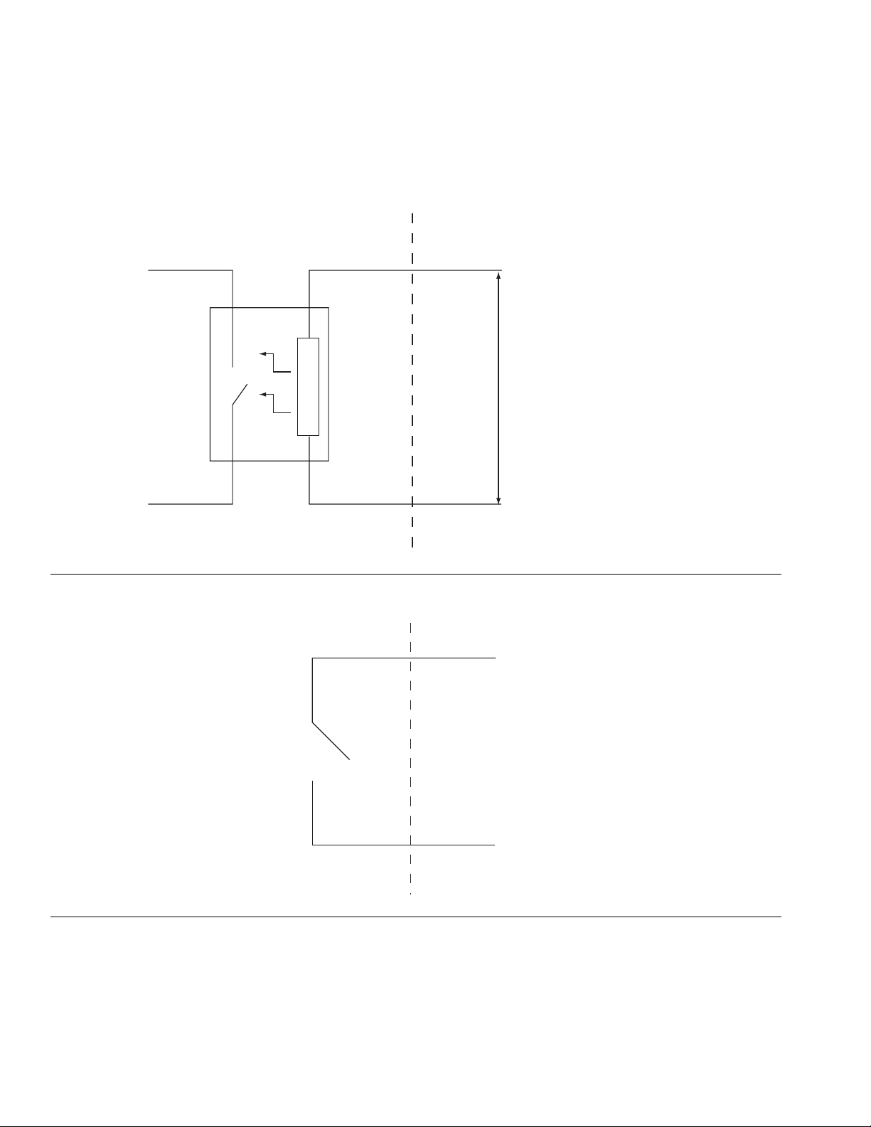
PLC Connection Block Diagrams
The following block diagrams show how to connect customer inputs and outputs to the InvisiPac MZLP. For convenience, each InvisiPac ships with connector kit 24P176. If a connector is lost or damaged, order kit 24P176 for
replacements.
FIG. 17: Customer Input
MZLP Customer In
MZLP Customer Out
Customer Output
Vin (no polarity)
30 VDC Max
Customer In
FIG. 18: Customer Output
250 VAC, 2A Max
To Customer Input
24 3A2347ZAA
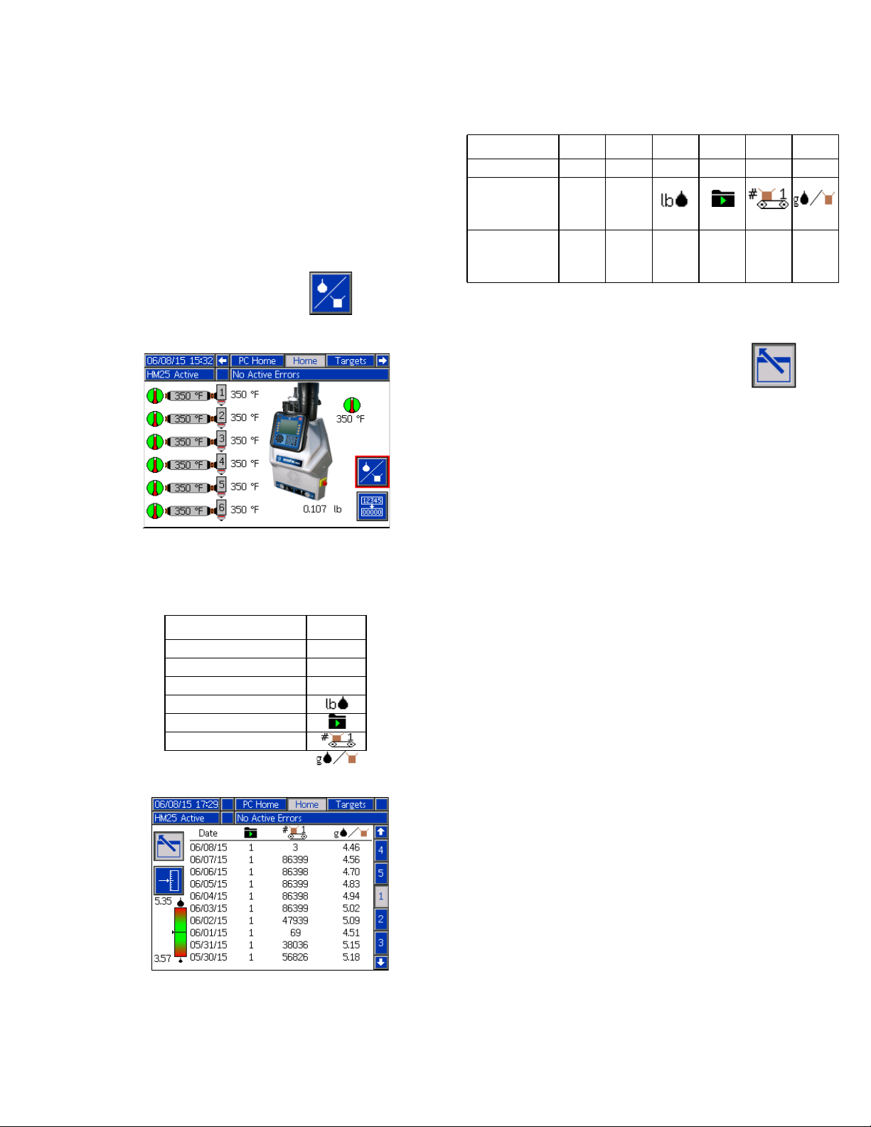
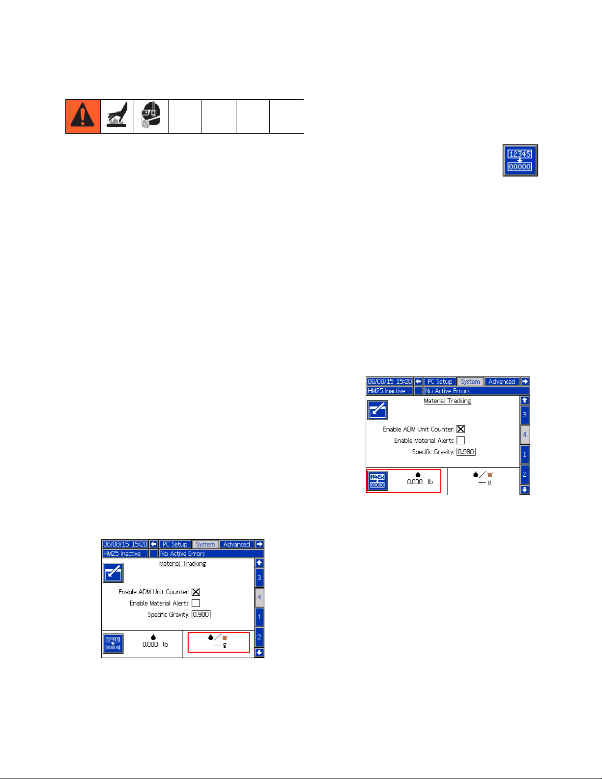
Material Tracking
The material tracking function allows the user to track
product counts and material usage for long term data
collection.
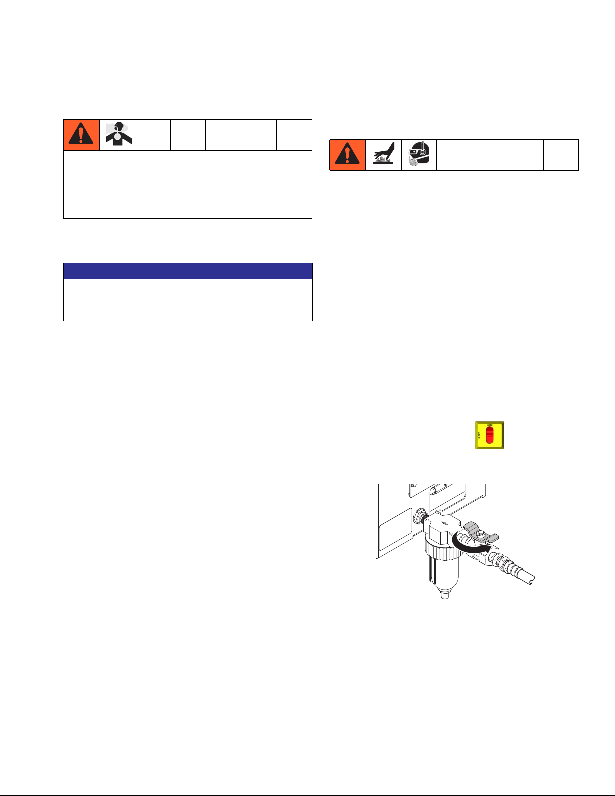
Viewing the Log
In order to view the log, navigate to the Home screen
System Type Date Cycles
InvisiPac XXX
InvisiPac w/
ADM Unit
Counter
InvisiPac w/
Pattern Con-
troller
XXX
XXX
Setup
X*
and press the material log softkey (see below).
Once inside the log (see below), use the up/down arrow
keys to view previous data. The log stores up to 200
rows of data including the following:
Item Icon
Date N/A
Cycles N/A
Material Used
Program
Products
Material per Product
* See Material Tracking Coverage for pattern Controller
Systems.
To exit the log, press the screen exit softkey .
Different system types will have different data shown in
the material log. The chart below outlines what data is
shown for each system type.
3A2347ZAA 25
Setup
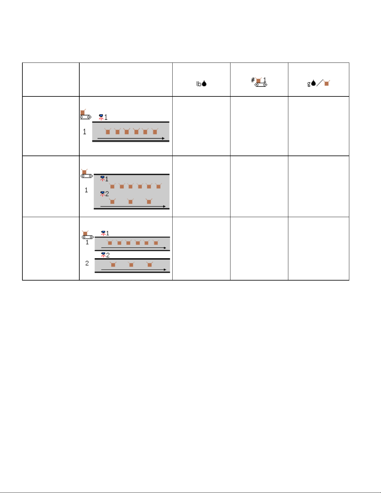
Material Tracking Coverage for Pattern Controller Systems
Material Used
Line Configuration Diagram
Single Line XX X
Multi-Unit Line XX
Multi-Line XX
()
Products per Line
()
Material per Product
( )
X*
**
* Products on both parts of the line must be the same in order to generate accurate material per product data.
** Accurate material per product data cannot be generated for multi-line configurations (assumes different products).
26 3A2347ZAA
Setup
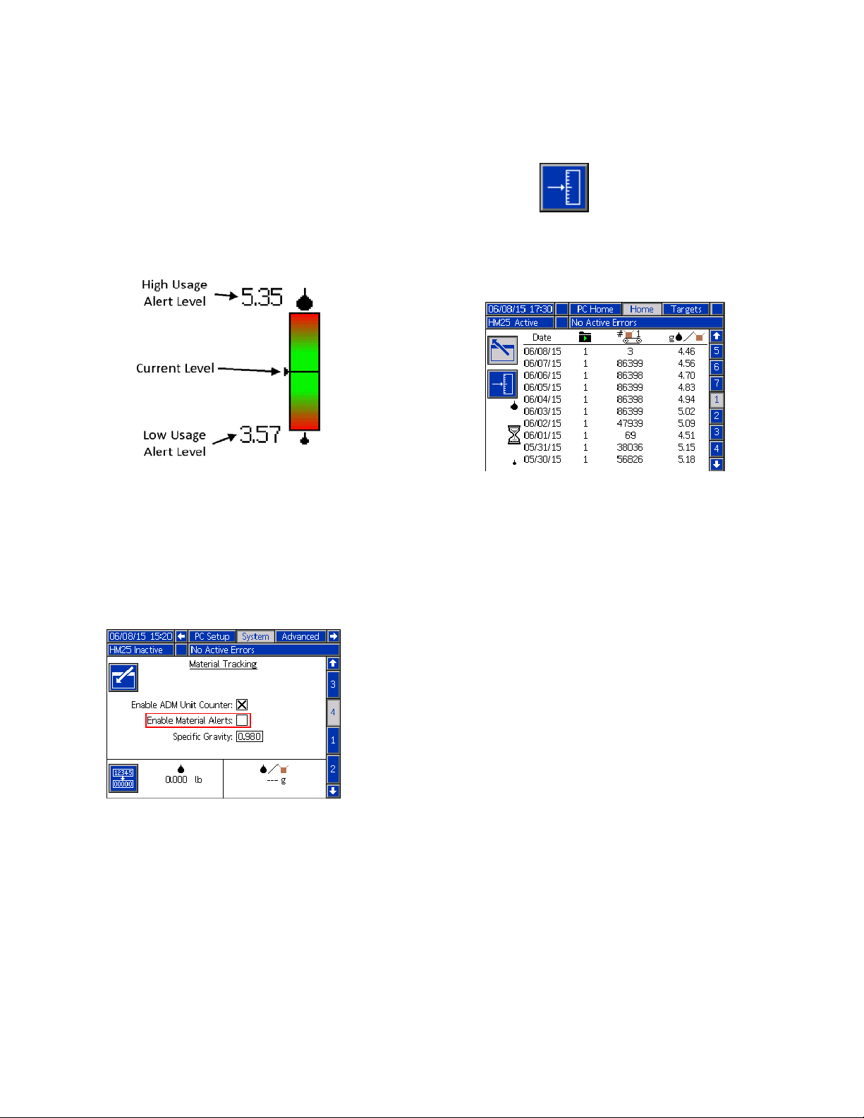
Calibration
Perform the following steps to calibrate the material
tracking function:
1. Navigate tj the material Tracking Screen (Screen 4
of the System chapter).
2. To calibrate using the tape and scrape method:
a. Obtain a scale.
b. Place tape on a procudt(s) in locations where
material is dispensed.
c. Run normal production (un-taped products) until
a value appears in the grams per product label
(this could take several minutes of production).
d. Run taped products(s) through line and allow
material to cool and harden on the tape.
3. To calibrate using the purge method:
a. Obtain a scale and a container.
b. Reset the calibration weight totalizer by press-
ing and holding the reset softkey .
c. Tare scale with empty container and purge at
least 1 lb. of material into the container.
d. Weigh container with material.
e. Adjust the specific gravity setting until the
weight displayed in the totalizer matches the
value measured by the scale using the following
formula:
New SG Value = Durrent SG Value x Measured Weight /
Displayed Weight
e. Scrape all material from product and place on
scale.
f. Adjust the specific gravity setting until the grams
per product displayed matches the value measured by the scale using the following formula:
New SG Value = Current SG Value x Measured Grams
per Product / Displayed Grams per Product
3A2347ZAA 27
Setup
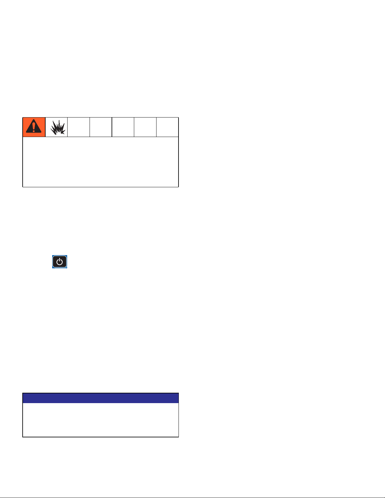
Material Alerts
This feature can be used ot monitor material usage
based on a target material per unit value. If material
alerts are enabled the system wil lrecord an event every
time the system deviates over 20% from the target. The
material alert information can be seen in the bottom left
corner of the material log (see image below).
Enable/Disable Material Alerts
To enable/disable material alerts, select/deselect the
Enable Material Alerts setting on the Material Tracking
Screen (Screen 4 of the System chapter).
Reset Material Target
To reset the material target value, press the reset mate-
rial target softkey . An hourglass will appear
indicating that the system is learning the new target
(current machine output).
NOTE: the material target will be automatically reset
whenever a Pattern Controller setting is changed (e.g.
switch from solid bead to stitched bead).
28 3A2347ZAA
Operation
Heating and dispensing hot melt adhesive may
create potentially harmful vapors. Read material
manufacturer’s warnings and material MSDS to know
specific hazards and precautions. Ventilation of the
work area may be required.
NOTE: See AppendixA-ADMon page 111 for
detailed ADM information.
Operation
Initial Startup and Prime
NOTE: All setup procedures must be completed prior to
initial startup. See Setup on page 13.
NOTE: Only 1/4 in. (6 mm) round hot melt adhesive pel-
lets can be used in the InvisiPac system. PSA-type
adhesive pellets will not work in the InvisiPac system.
NOTICE
To prevent damage to soft key buttons, do not press
the buttons with sharp objects such as pens, plastic
cards, or fingernails.
NOTE: See Appendix B - USB Downloading, Uploading on page 117 for detailed USB information.
Overview
The system includes a vacuum transfer system that
pulls the adhesive pellets into the system as needed.
Once melted, the adhesive enters the pump where it is
pumped into the heated hoses then to the heated guns.
The gun then briefly opens to dispense the desired
quantity of adhesive.
Even though the system rises to operating temperature
quickly, there is a Schedule function in the ADM that
eliminates waiting for the system to heat up. The Schedule function automatically enables the heating system at
the user-specified times so the system is ready to dispense when a shift begins. The Schedule function also
disables the heating system at user-specified times to
ensure the heating system is disabled when not being
used.
1. Direct the guns into an appropriate waste container.
2. Verify the shaker inlet is at the bottom of the empty
adhesive pellets container. Optional vibrating adhesive pellets container, part 24R136, is available.
See Accessories on page 94.
NOTE: The shaker inlet must be completely covered in
adhesive pellets to effectively pull pellets into the tube.
3. Fill adhesive pellets container with hot melt adhesive pellets.
4. Turn main power switch ON .
5. Open system air inlet ball valve.
WLE
6. Use pump air pressure regulator (C) to adjust pump
air pressure to 0. See F
3A2347ZAA 29
IG. 1 on page 8.
Operation
7. Use vacuum transfer air pressure regulator (E) to
adjust vacuum transfer air pressure setting to
40-100 psi (280-690 kPa, 2.8-6.9 bar). Recommended setting is 60 psi (414 kPa, 4.1 bar). See
FIG. 1 on page 8.
NOTE: Vacuum transfer will not begin operating until
pump reaches operating temperature.
To prevent fire and explosion, never exceed the
cleaning fluid’s rated temperature. If the system was
just flushed, residual cleaning fluid is still in the
system until the system is primed with adhesive. Do
not raise temperature above cleaning fluid rated
temperature until system is primed with adhesive.
NOTE: A new system may have residual oil due to testing at the factory prior to shipping. To prevent smoking,
make sure to perform the following step.
8. On new systems only: temporarily adjust the melter
temperature to 250°F (121°C). See Select ADM
Settings on page 20 for instructions.
12. With the guns open and the system up to temperature, slowly increase pump air pressure until the
pump begins to run very slowly. Approximately 20
psi (140 kPa, 1.4 bar) should be sufficient.
NOTE: Operation may be erratic below 20 psi (140 kPa,
1.4 bar).
13. Continue running the pump until clean, air-free
material is dispensed from each gun.
14. When each gun is fully primed, adjust pump to
desired pressure setting:
a. Adjust pump pressure to between 20-100 psi
(140-690 kPa, 1.4-6.9 bar).
b. Use separate gun controller to repeatedly open
and close each gun while inspecting the dispense pattern.
c. Repeat until desired dispense pattern is
achieved.
Manual Refill
9. Press to enable the heaters and pump.
NOTE: When system is up to temperature, the pump will
be activated automatically but will not start because
there is no air pressure supplied to the pump.
NOTE: When the melter is up to temperature, the
auto-fill function will initiate to fill the funnel with pellets.
10. On new systems only: After the melter has reached
250°F (121°C) and the funnel is filled with pellets,
set the melter temperature back to the desired operating temperature. See Select ADM Settings on
page 20 for instructions.
11. Use separate gun controller to open the guns and
keep them open.
NOTICE
In the following step, to prevent damage to the pump
due to pump cavitation, do not supply more than 20 psi
(140 kPa, 1.4 bar) air pressure to the pump until the
system is fully primed.
NOTE: Use Automatic Refill whenever possible. The
system uses Automatic Refill by default and must be
manually changed to Manual Refill. Only use Manual
Refill if the Automatic Refill system is not functioning
properly and cannot be fixed in a timely manner. Perform service to automatic feed system as soon as possible to limit debris buildup on feed cap.
It is recommended to maintain a minimum flow rate of
1.5 lb/hour to prevent material from melting within the
feed cap and funnel. If production rate is below
1.5 lb/hour or system sits at temperature without dispensing for extended periods of time, use manual refilling with caution. System flow rate can be monitored by
enabling the Diagnostic screen.
1. On the System 3 screen (in the Setup screens),
select “Manual” from the Refill mode dropdown.
2. Remove the phillips head screws then remove the
funnel cap from the funnel.
30 3A2347ZAA
 Loading...