

Graco InvisiPac HM25, InvisiPac HM25c, InvisiPac HM50 Operation, Repair, And Parts
Operation, Repair and Parts
InvisiPac®
334784G
Pattern Controller
To control fluid dispense valves of adhesive supply equipment. For professional use only.
Not approved for use in explosive atmospheres or hazardous locations.
See page 3 for model information and Agency approvals.
Important Safety Instructions
Read all warnings and instructions in this manual
and related manuals. Save these instructions.
EN
WLD

Contents
Models . . . . . . . . . . . . . . . . . . . . . . . . . . . . . . . . . . . 3
Approvals . . . . . . . . . . . . . . . . . . . . . . . . . . . . . . . . . 3
Related Manuals . . . . . . . . . . . . . . . . . . . . . . . . . . . 3
Warnings . . . . . . . . . . . . . . . . . . . . . . . . . . . . . . . . . 4
Overview . . . . . . . . . . . . . . . . . . . . . . . . . . . . . . . . . . 7
Component Identification (Internal Models - HM25c)
8
Component Identification
(Internal Models - HM25 and HM50) . . . . . . . . . 9
Component Identification (External Models) . . . 10
Installation - Internal Models (HM25c) . . . . . . . . . 11
Connect Pattern Control Board . . . . . . . . . . . . . 11
Installation - Internal Models (HM25 and HM50) . 12
Connect Pattern Control Board . . . . . . . . . . . . . 12
Connect Power Supply and Advanced Display
Module . . . . . . . . . . . . . . . . . . . . . . . . . . . . 13
Install Control Board into InvisiPac System . . . 14
Installation - External Models . . . . . . . . . . . . . . . . 15
Mounting . . . . . . . . . . . . . . . . . . . . . . . . . . . . . . 15
Connect Advanced Display Module (ADM) . . . . 15
Connect Pattern Control Board . . . . . . . . . . . . . 16
Connect Electrical Cord . . . . . . . . . . . . . . . . . . 17
Wire Pattern Control Board . . . . . . . . . . . . . . . . . 18
Valve Installation . . . . . . . . . . . . . . . . . . . . . . . . 18
Trigger Installation . . . . . . . . . . . . . . . . . . . . . . 18
PLC Inputs and Outputs Installation (optional) . 19
Encoder Installation
(PC-8e only) . . . . . . . . . . . . . . . . . . . . . . . . 20
Run Up Installation (PC-8e only) . . . . . . . . . . . 20
Initial Startup . . . . . . . . . . . . . . . . . . . . . . . . . . . . . 21
Software Update . . . . . . . . . . . . . . . . . . . . . . . . 21
Key Token . . . . . . . . . . . . . . . . . . . . . . . . . . . . . 21
Screens . . . . . . . . . . . . . . . . . . . . . . . . . . . . . . . . . . 22
Screen Maps . . . . . . . . . . . . . . . . . . . . . . . . . . . 22
HMI Interface . . . . . . . . . . . . . . . . . . . . . . . . . . 23
PC Screens . . . . . . . . . . . . . . . . . . . . . . . . . . . . 24
Advanced Screens . . . . . . . . . . . . . . . . . . . . . . 35
Stitching . . . . . . . . . . . . . . . . . . . . . . . . . . . . . . . . . 37
Random Length Bead Mode . . . . . . . . . . . . . . . . . 38
Mirror Mode . . . . . . . . . . . . . . . . . . . . . . . . . . . . . . 39
Calibration . . . . . . . . . . . . . . . . . . . . . . . . . . . . . . . 40
Gun Compensation (optional) . . . . . . . . . . . . . . 40
Line Speed . . . . . . . . . . . . . . . . . . . . . . . . . . . . 41
Run Up Control (PC-8e only) . . . . . . . . . . . . . . . 42
Modulated Bead (PC-8e Only) . . . . . . . . . . . . . 43
Verification . . . . . . . . . . . . . . . . . . . . . . . . . . . . . . . 44
Valves . . . . . . . . . . . . . . . . . . . . . . . . . . . . . . . . 44
Triggers . . . . . . . . . . . . . . . . . . . . . . . . . . . . . . . 44
Encoder . . . . . . . . . . . . . . . . . . . . . . . . . . . . . . . 44
Run Up Control . . . . . . . . . . . . . . . . . . . . . . . . . 44
PLC Inputs . . . . . . . . . . . . . . . . . . . . . . . . . . . . . 44
Troubleshooting . . . . . . . . . . . . . . . . . . . . . . . . . . . 45
Error Codes . . . . . . . . . . . . . . . . . . . . . . . . . . . . 45
Display . . . . . . . . . . . . . . . . . . . . . . . . . . . . . . . . 46
Pattern . . . . . . . . . . . . . . . . . . . . . . . . . . . . . . . . 46
Valve . . . . . . . . . . . . . . . . . . . . . . . . . . . . . . . . . 47
Trigger . . . . . . . . . . . . . . . . . . . . . . . . . . . . . . . . 47
Encoder . . . . . . . . . . . . . . . . . . . . . . . . . . . . . . . 47
Run Up . . . . . . . . . . . . . . . . . . . . . . . . . . . . . . . 48
PLC Inputs and Outputs . . . . . . . . . . . . . . . . . . 48
Software Update Procedure . . . . . . . . . . . . . . . . . 49
USB Download . . . . . . . . . . . . . . . . . . . . . . . . . . . . 50
Download Procedure . . . . . . . . . . . . . . . . . . . . . 50
Accessing Files . . . . . . . . . . . . . . . . . . . . . . . . . 50
USB Logs . . . . . . . . . . . . . . . . . . . . . . . . . . . . . 50
Parts . . . . . . . . . . . . . . . . . . . . . . . . . . . . . . . . . . . . 51
External Models . . . . . . . . . . . . . . . . . . . . . . . . . 51
Internal Models (HM25c) . . . . . . . . . . . . . . . . . . . . 53
Internal Models (HM25 and HM50) . . . . . . . . . . 54
Kits . . . . . . . . . . . . . . . . . . . . . . . . . . . . . . . . . . . 55
Wiring Diagrams . . . . . . . . . . . . . . . . . . . . . . . . . . 58
Internal Pattern Controller (HM25 and HM50
Systems with AWB) . . . . . . . . . . . . . . . . . . 58
Internal Pattern Controller (HM25 Systems with DIN
Rail) . . . . . . . . . . . . . . . . . . . . . . . . . . . . . . . 59
External Models . . . . . . . . . . . . . . . . . . . . . . . . . 60
Dimensioned Drawings . . . . . . . . . . . . . . . . . . . . . 61
Technical Specifications . . . . . . . . . . . . . . . . . . . . 64
Notes . . . . . . . . . . . . . . . . . . . . . . . . . . . . . . . . . . . . 65
Graco Standard Warranty . . . . . . . . . . . . . . . . . . . 66
2 334784G

Models
Internal Models (HM25c)
Used to upgrade InvisiPac HM25c systems to include pattern control.
Part Type Description Contents
25M526 PC-8* Time or distance mode, no encoder Pattern controller
* Order kit 17F712 to upgrade to PC-8e.
Internal Models (HM25 and HM50)
Used to upgrade InvisiPac HM25 and HM50 systems to include pattern control.
Part Type Description Contents
24X640 PC-8 Time or distance mode, no encoder Internal pattern controller
24X641 PC-8e Time or distance mode, with or without encoder
Run up control (optional)
Internal pattern controller
Key token for encoder and run up
Models
External Integrated Models
Used to connect a separate pattern control enclosure to an InvisiPac system (compatible with all InvisiPac systems)
Part Type Description Contents
24X523 PC-8 Time or distance mode, no encoder Pattern controller
24X524 PC-8e Time or distance mode, with or without encoder
Run up control (optional)
Pattern controller
Key token for encoder and run up
External Stand Alone Models
Used for applications without an InvisiPac system
Part Type Description Contents
24X525 PC-8 Time or distance mode, no encoder Pattern controller
Advanced display module
24X526 PC-8e Time or distance mode, with or without encoder
Run up control (optional)
Pattern controller
Advanced display module
Key token for encoder and run up
Approvals Related Manuals
Part Description Approvals
127971 External pattern controller CE, ETL, cETL
24W293 Internal pattern controller
(HM25c)
24X521 Internal pattern controller
(HM25 and HM50)
24E451 Advanced display module CE, ETL, cETL
CE, ETL, cETL
CE, ETL, cETL
Part Description
3A4938
333347
334934 Run Up Pressure Kit
InvisiPac HM25c Tank-Free
Delivery System
InvisiPac HM25 and HM50 Tank-Free
Hot Melt Delivery System
™
Hot Melt
™
334784G 3
Warnings
WARNING
Warnings
The following warnings are for the setup, use, grounding, maintenance, and repair of this equipment. The exclamation point symbol alerts you to a general warning and the hazard symbols refer to procedure-specific risks. When
these symbols appear in the body of this manual or on warning labels, refer back to these Warnings. Product-specific
hazard symbols and warnings not covered in this section may appear throughout the body of this manual where
applicable.
ELECTRIC SHOCK HAZARD
This equipment must be grounded. Improper grounding, setup, or usage of the system can cause
electric shock.
• Turn off and disconnect power at main switch before disconnecting any cables and before
servicing or installing equipment.
• Connect only to grounded power source.
• All electrical wiring must be done by a qualified electrician and comply with all local codes and
regulations.
EQUIPMENT MISUSE HAZARD
Misuse can cause death or serious injury.
• Do not operate the unit when fatigued or under the influence of drugs or alcohol.
• Do not exceed the maximum working pressure or temperature rating of the lowest rated system
component. See Technical Specifications in all equipment manuals.
• Use fluids and solvents that are compatible with equipment wetted parts. See Technical Specifi-
cations in all equipment manuals. Read fluid and solvent manufacturer’s warnings. For complete
information about your material, request MSDS from distributor or retailer.
• Do not leave the work area while equipment is energized or under pressure.
• Turn off all equipment and follow the Pressure Relief Procedure when equipment is not in use.
• Check equipment daily. Repair or replace worn or damaged parts immediately with genuine
• manufacturer’s replacement parts only.
• Do not alter or modify equipment. Alterations or modifications may void agency approvals and create safety hazards.
• Make sure all equipment is rated and approved for the environment in which you are using it.
• Use equipment only for its intended purpose. Call your distributor for information.
• Route hoses and cables away from traffic areas, sharp edges, moving parts, and hot surfaces.
• Do not kink or over bend hoses or use hoses to pull equipment.
• Keep children and animals away from work area.
• Comply with all applicable safety regulations.
BURN HAZARD
Equipment surfaces and fluid that is heated can become very hot during operation. To avoid severe
burns.
• Do not touch hot fluid or equipment.
4 334784G
Warnings
WARNING
SKIN JECTION HAZARD
High-pressure fluid from dispensing device, hose leaks, or ruptured components will pierce skin. This
may look like just a cut, but it is a serious injury that can result in amputation. Get immediate surgi-
cal treatment.
• Do not point dispensing device at anyone or at any part of the body.
• Do not put your hand over the fluid outlet.
• Do not stop or deflect leaks with your hand, body, glove, or rag.
• Follow the Pressure Relief Procedure when you stop dispensing and before cleaning, checking,
or servicing equipment.
• Tighten all fluid connections before operating the equipment.
• Check hoses and couplings daily. Replace worn or damaged parts immediately.
MOVING PARTS HAZARD
Moving parts can pinch, cut or amputate fingers and other body parts.
• Keep clear of moving parts.
• Do not operate equipment with protective guards or covers removed.
• Equipment can start without warning. Before checking, moving, or servicing equipment, follow the
Pressure Relief Procedure and disconnect all power sources.
FIRE AND EXPLOSION HAZARD
Flammable fumes, such as solvent and paint fumes, in work area can ignite or explode. To help prevent fire and explosion:
• Do not use solvent-based adhesives that can create an explosive atmosphere when processed.
• Use equipment only in well-ventilated area.
• Eliminate all ignition sources; such as pilot lights, cigarettes, portable electric lamps, and plastic
drop cloths (potential static sparking).
• Keep work area free of debris, including solvent, rags and gasoline.
• Do not plug or unplug power cords, or turn power or light switches on or off when flammable fumes
are present.
• Ground all equipment in the work area. See Grounding instructions.
• Use only grounded hoses.
• Stop operation immediately if static sparking occurs or you feel a shock. Do not use equipment
until you identify and correct the problem.
• Keep a working fire extinguisher in the work area.
334784G 5
Warnings
WARNING
TOXIC FLUID OR FUMES HAZARD
Toxic fluids or fumes can cause serious injury or death if splashed in the eyes or on skin, inhaled, or
swallowed.
• Read Safety Data Sheets (SDSs) to know the specific hazards of the fluids you are using.
• Store hazardous fluid in approved containers, and dispose of it according to applicable guidelines.
PERSONAL PROTECTIVE EQUIPMENT
Wear appropriate protective equipment when in the work area to help prevent serious injury,
including eye injury, hearing loss, inhalation of toxic fumes, and burns. Protective equipment includes
but is not limited to:
• Protective eyewear, and hearing protection.
• Respirators, protective clothing, and gloves as recommended by the fluid and solvent
manufacturer.
PRESSURIZED ALUMINUM PARTS HAZARD
Use of fluids that are incompatible with aluminum in pressurized equipment can cause serious
chemical reaction and equipment rupture. Failure to follow this warning can result in death, serious
injury, or property damage.
• Do not use 1,1,1-trichloroethane, methylene chloride, other halogenated hydrocarbon solvents or
fluids containing such solvents.
• Do not use chlorine bleach.
• Many other fluids may contain chemicals that can react with aluminum. Contact your material
supplier for compatibility.
6 334784G

Overview
Overview
InvisiPac pattern control systems can be integrated with InvisiPac systems or stand alone with any other equipment.
For all installations, the advanced display module (ADM) is used to make programming easy.
PC-8 controllers operate in time or distance mode without an encoder. Up to 8 guns and 4 independent triggers are
supported.
PC-8e controllers include the same features as PC-8 with the addition of distance based control using an encoder,
and run up control using an I/P or V/P pressure regulator.
Features of the PC-8 and PC-8e:
Feature
Gun outputs
Trigger inputs
Encoder
Run up control
Program storage
PLC enable / disable
PLC alarm output
PLC program select
Password protection
Integrated power supply
For more information, see Technical Specifications,
page 64.
8
4
2 (PC-8e only)
2 (PC-8e only)
50
Yes
Yes
Yes
Yes
Yes
Details
334784G 7
Component Identification (Internal Models - HM25c)
/
.
-
+
WLE
6
3
&
7
Installed onto InvisiPac System
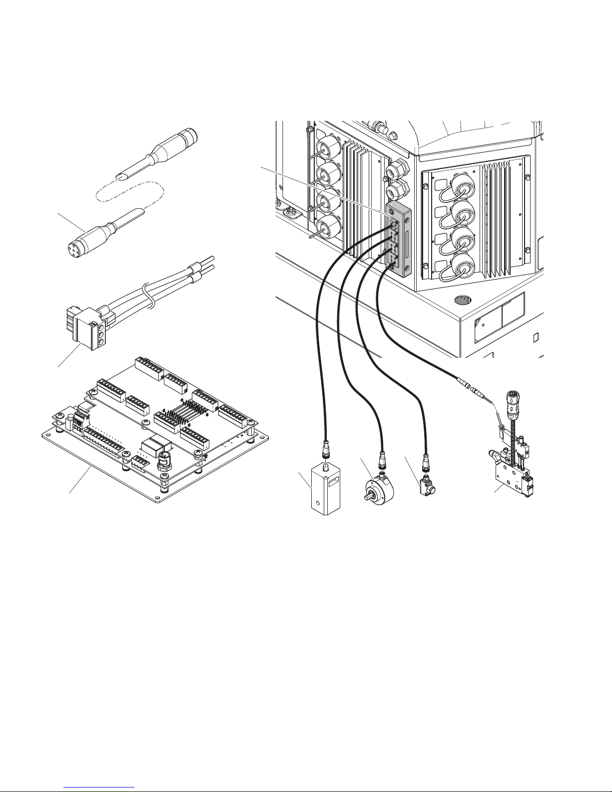
Component Identification (Internal Models - HM25c)
Key
C Communication cable
HValve
J Trigger
K Encoder
Key
L Run up
P Power harness
S Control board
T Cord grip
8 334784G
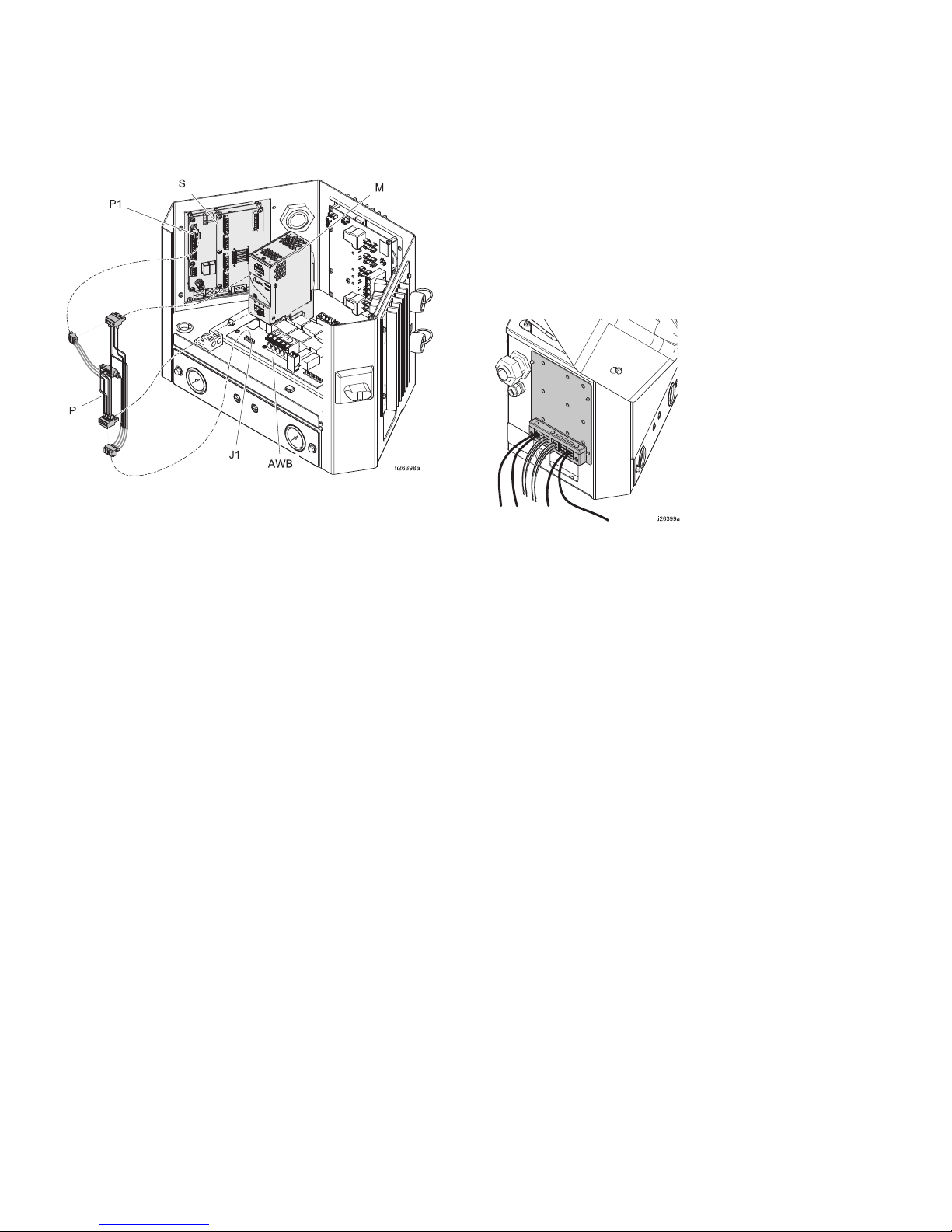
Component Identification (Internal Models - HM25 and HM50)
Installed onto InvisiPac System
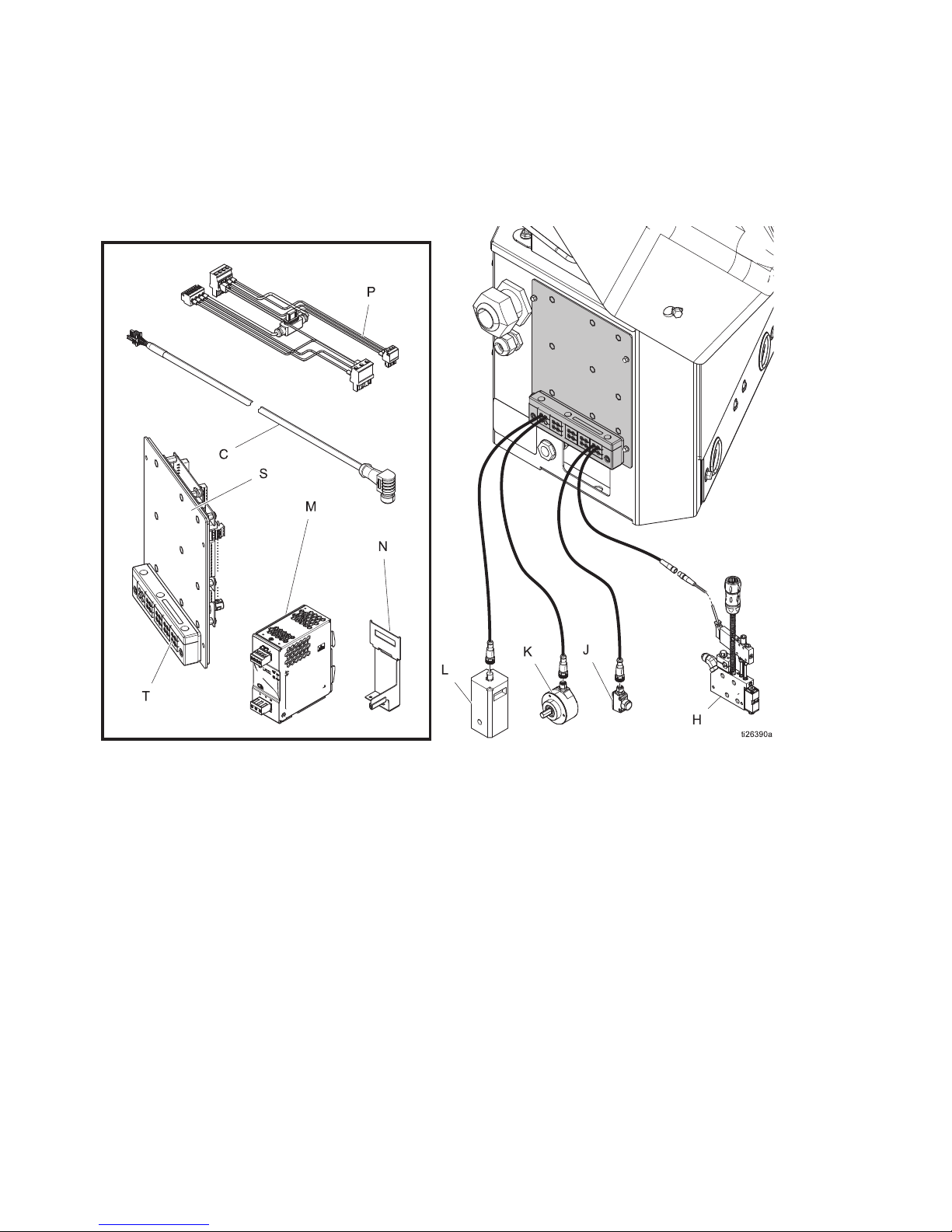
Component Identification
(Internal Models - HM25 and HM50)
Key
C
H
J
K
L
334784G 9
Communication cable
Valve
Trigger
Encoder
Run Up
Key
M
N
P
S
T
Power supply
Power supply bracket
Power harness
Control board
Cord grip

Component Identification (External Models)
7
7
7
3
6
%
'
&
1
/
.
-
+
$
0
WLE
(
Component Identification (External Models)
Key
A
B
C
D
E
H
J
Pattern controller
Power switch
Communication cable
ADM
USB port
Valve
Trigger
Key
K
L
M
N
P
S
T
Encoder
Run up
Inside view of pattern controller
Customer power board (not included)
Ground terminal
Control board
Cord grips (I/O x2 power)
10 334784G
Installation - Internal Models (HM25c)
WLD
0
WLD
7
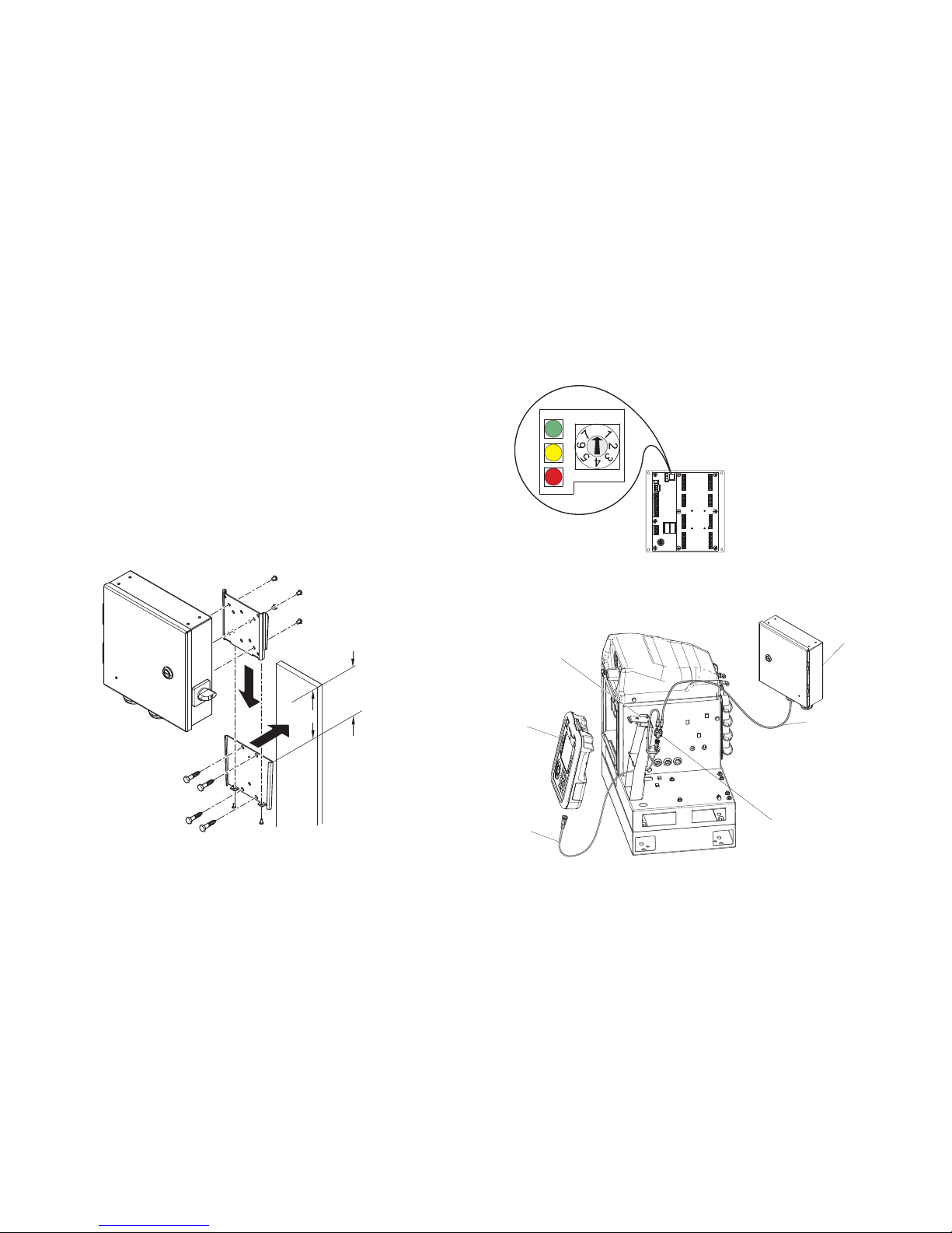
Installation - Internal Models (HM25c)
Connect Pattern Control Board
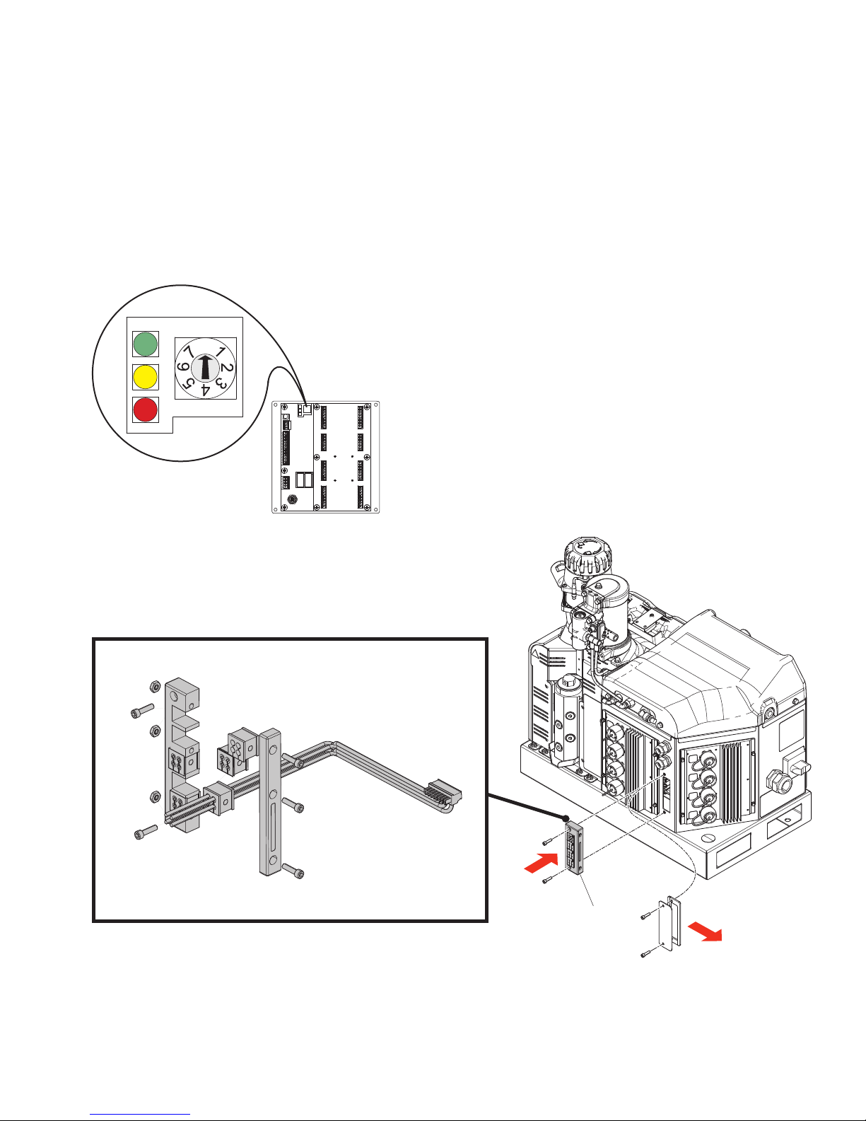
1. Set pattern control system type selector switch to 0.
NOTE: The system must be powered off for a
change in system type to have an effect.
2. Remove cord grip assembly (T) from back of InvisiPac system and remove inserts. Inserts with grip
tightly on most M8 and M12 cables and expand and
compress to accept cables larger than the apparent
hole size.
3. Install valve signal wires, trigger signal wires, PLC
wires (optional). See Wire Pattern Control Board,
page 18.
4. Route cables through the opening in the back of the
InvisiPac enclosure as shown.
5. Apply cord grip inserts over cables and replace into
frame. Replace frame onto back of InvisiPac enclosure.
6. Remove excess slack from the cables but do not
pull tight. Tighten cord grip frame on inserts to
secure.
334784G 11

Installation - Internal Models (HM25 and HM50)
0
Installation - Internal Models (HM25 and HM50)
Connect Pattern Control Board
1. Set pattern control system type selector switch to 0.
NOTE: The system must be powered off for a
change in system type to have an effect.
WLD
2. Remove cord grip assembly (T) from pattern control
board (S) and remove inserts. Inserts will grip tightly
on most M8 and M12 cables and will expand and
compress to accept cables larger than the apparent
hole size.
3. Install valve signal wires, trigger signal wires, PLC
wires (optional) and encoder and run up wires
(PC-8e only). See Wire Pattern Control Board,
page 18.
4. Route cables through the opening in the pattern
control board back panel as shown.
5. Apply cord grip inserts over cables and replace into
frame. Replace frame onto pattern control panel.
6. Remove excess slack from cables but do not pull
tight. Tighten cord grip frame on inserts to secure.
12 334784G
Installation - Internal Models (HM25 and HM50)
Connect Power Supply and Advanced Display Module
NOTE: If the internal pattern controller is being installed
into a first generation HM25 with DIN rail writing, additional connections must be made.
Install Kit 24Y171 has the necessary components and
instructions to perform this installation. See Kits, page
55.
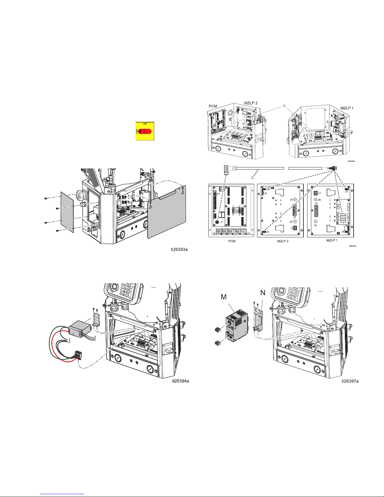
1. Turn main power switch OFF.
2. Remove panel door, then remove blanking plate
from left-hand side of system electrical enclosure.
4. Connect communication cable (C) to open J3 connector (or J6, if J3 is used) on MZLP board. If connecting to MZLP #2, loop extra cable length along
edge of electrical enclosure.
3. Remove connector from AWB terminal pins J1 and
remove the power supply and harness from mounting bracket. Unscrew mounting bracket from AWB.
5. Remove blue connectors from terminals of power
supply W and discard or set aside. Install new
power supply bracket (N) onto AWB and clip new
power supply (M) into place.
334784G 13
Installation - Internal Models (HM25 and HM50)
6. Connect power harness (P) to AWB terminal pins J1
and the input and output terminals of power supply.
Install Control Board into
InvisiPac System
1. Mount board into open space on left-hand side of
electrical enclosure. Use serrated-flange screws.
2. Connect power harness to power control board terminal P1, and connect communication cable to pattern control board terminal P4.
3. Replace system electrical enclosure door.
14 334784G
Installation - External Models
WLF
13 in (330.2 mm)
Clearance
WLD
0
$
'
%
Installation - External Models
Mounting
The pattern controller and ADM can be mounted using
the included VESA-compatible brackets and mounting
software.
1. Unscrew the two lower screws to uncouple the
“wall” portion of the bracket.
2. Securely mount the bracket in the desired location.
3. Slide the controller onto the bracket and tighten the
two screws for permanent fastening.
ALTERNATIVE METHOD: Remove mounting hardware
and mount directly to any surface.
NOTE: Make sure at least 13 in. of clearance is available above the top of the mounting bracket in order to
slide the enclosure in and out of the wall mount.
Connect Advanced Display
Module (ADM)
Integrate with InvisiPac HM25c
1. Set pattern control system type selector switch to 0.
NOTE: The system must be powered off for a
change in system type to have an effect.
2. Disconnect the CAN cable from the ADM (D) and
connect it to one of the male ends of the splitter (2).
NOTE: To make repairing the system easier, locate the
system so that it is easily accessible and has sufficient
lighting.
334784G 15
WLE
3. Connect the CAN cable from the pattern controller
enclosure (A) to the other male end of the splitter
(2).
4. Connect the male end of the short CAN cable contained in the pattern controller kit (3) to the female
end of the splitter (2).
5. Connect female end of the short CAN cable (3) to
the ADM.
6. Use zip ties to attach the CAN cables and splitter to
the ADM bracket (B).
Installation - External Models
WLD
0
WLD
0
&
WLD
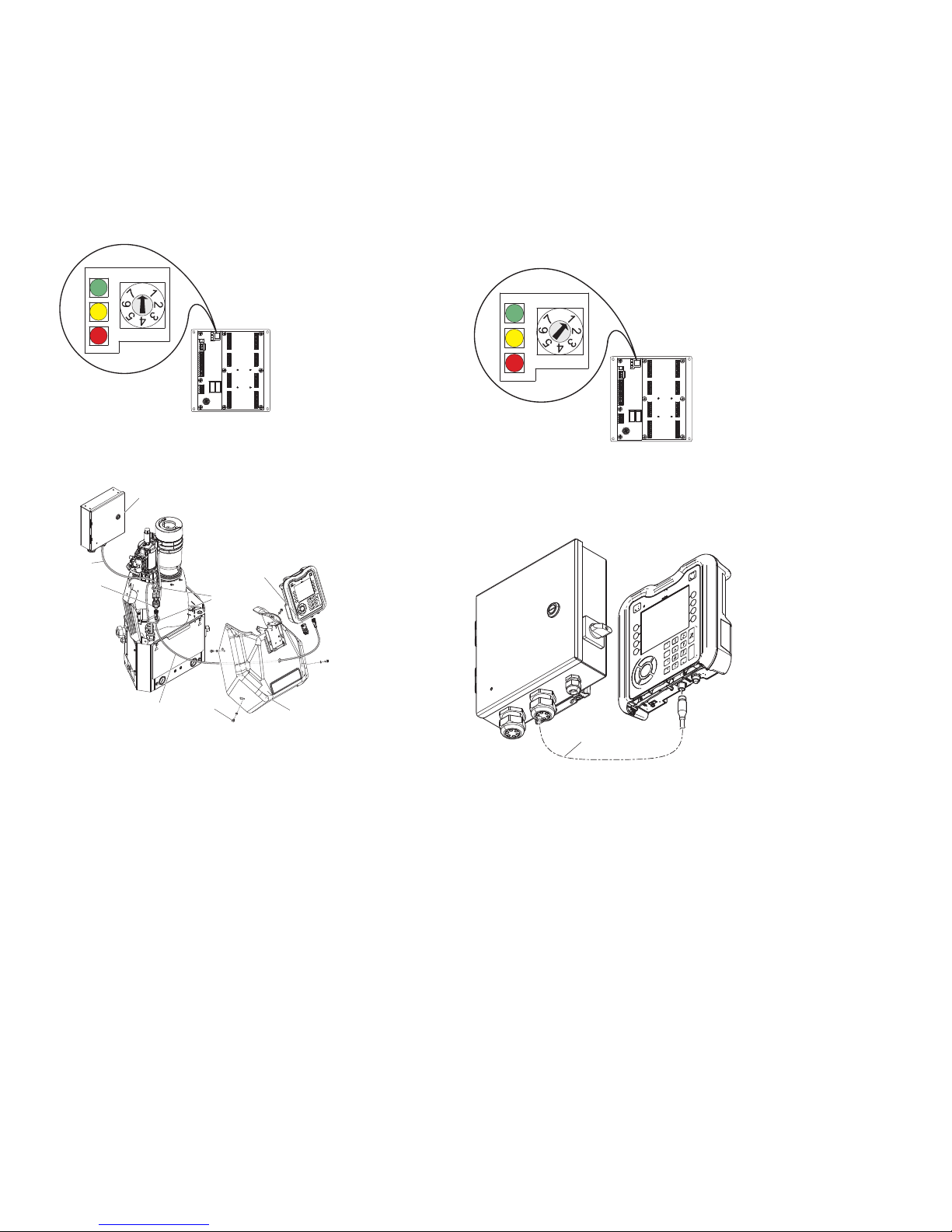
Integrate with InvisiPac (HM25 or HM50)
1. Set pattern control system type selector switch to 0.
NOTE: The system must be powered off for a
change in system type to have an effect.
2. Disconnect the CAN cable from the ADM (D), push
the cable through the plastic shroud (B), the remove
the shroud from the system.
$
Stand Alone
1. Set the pattern control system type selector switch
to 1.
NOTE: The system must be powered off for a
change in system type to have an effect.
2. Mount the ADM using the provided bracket
3. Connect the CAN cable (C) between the pattern
controller and the ADM
&
%
WLD
3. Connect the CAN cable from the ADM (D) to one of
the male ends of the splitter (2).
4. Connect the CAN cable from the pattern controller
(A) to the other male end of the splitter (2).
5. Connect the male end of the short CAN cable contained in pattern controller kit (3) to the female end
of the splitter.
6. Push the free end of the short CAN cable (3)
through the shroud and connect the female end to
the ADM.
7. Use zip ties (4) to attach the CAN cable bundle to
the other vertical bundle of cables.
Connect Pattern Control Board
See Wire Pattern Control Board, page 18.
1. Install triggers and valves
2. Install PLC inputs and outputs (optional)
3. Install encoder (PC-8e only)
4. Install run up (optional, PC-8e only)
16 334784G
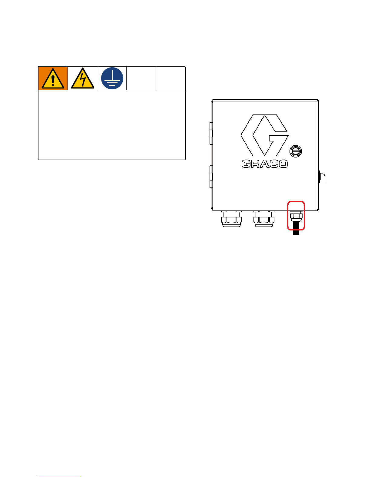
Connect Electrical Cord
Improper wiring may cause electric shock or other
serious injury if work is not performed properly.
Have a qualified electrician perform any electrical
work. Be sure your installation complies with all
National, State, and Local safety and fire codes.
The equipment must be grounded to reduce the
risk of electric shock. Improper grounding can
cause electric shock. Grounding provides an
escape wire for the electric current.
The pattern controller system is equipped with a ground
terminal. Have a qualified electrician ground the system
using this terminal.
Electrical power enters through the smaller cord grip on
the right side of the enclosure (see figure). The power
cord can be further secured inside the enclosure with
the provided zip-tie and tie mount.
Installation - External Models
2. Connect earth ground to the grounding terminal.
3. Verify that the cord grip securely tightens around the
power cord. Use a wrench to tighten, if necessary.
1. Install power wires (L1/L2 or L/N) into terminals 2
and 4 on the disconnect switch. The switch accepts
solid or stranded 12 AWG and 14 AWG wire. For
ratings, see Technical Specifications, page 64.
NOTE: The power switch housing can be removed
for easy wiring using the red tab on top of the
switch.
334784G 17
Wire Pattern Control Board
Wire Pattern Control Board
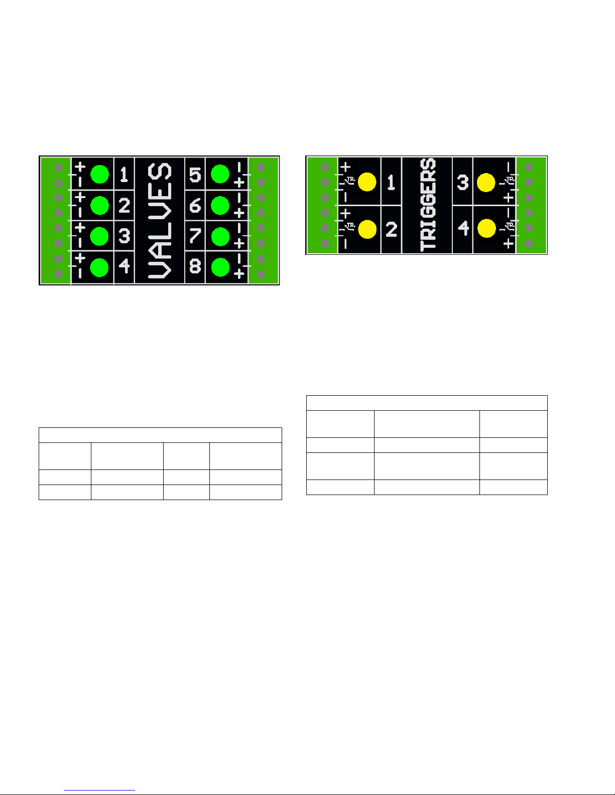
Valve Installation
1. Connect up to 8 valves.
NOTE: Control voltage is 24 VDC with a limit of 1
amp per output and 6 amps total.
NOTE: Green LEDs indicate the status of each
valve.
NOTE: DIN cable black wires are labeled 1 and 2. 1
is plus and 2 is minus.
Standard Wiring Colors
Terminal
Cable
Plus (+) 24V Supply Brown Black 1
Minus (-) Return Blue Black 2
Function M8
Cable
DIN Cable
Trigger Installation
1. Connect up to 4 NPN, PNP, or dry contact triggers.
NOTE: Supplied voltage (+) is 24 VDC
2. Connect the two wires between TR and minus (-) to
install a dry contact.
NOTE: Yellow LEDs indicate the status of each trigger. Polarity can be inverted if needed. See Trigger
Setup, page 31.
Standard Wiring Colors
Terminal Function M8 or M12
Cable
Plus (+) 24V Supply Brown
TR NPN, PNP, or dry con-
tact
Minus (-) Return (or dry contact) Blue
Black or white
18 334784G

PLC Inputs and Outputs Installation (optional)
PCM PLC Output
Customer Input
24 VDC, 240VAC, 2A
Max
To Customer Input
PCM PLC Input
Customer Output
Vin (no polarity)
30 VDC Max
Dry Contact
(customer supplied)
Customer
PCM
(Jumper Wire)
“+”
(24 VDC)
“-”
(GND)
Functions:
Type Function Description
Input ENABLE Turns the controller on and off (rising edge enables, falling edge disables).
Integrated systems: Turn the heat on/off using the InvisiPac PLC input
(instead of this input). The pattern controller will be turned on by the InvisiPac
system once the InvisiPac goes inactive.
DISABLE Disables the pattern controller (pull high to disable)
NOTE: DISABLE polarity can be changed with the invert disable input setting.
See General Setup (Screen 4), page 32.
PROGRAM
SELECT
Output ALARM 1 Relay opens for active alarm(s) on Line 1
ALARM 2 Relay opens for active alarm(s) on Line 2
Specifications
Inputs Outputs
• Bipolar Input • Dry contact output
• Electrically isolated • 0-24 VDC or 0-240 VAC
• 0-30 VDC • 2A max
• Min. 10 VDC to assert
• Sinks 10 mA at 24 VDC
Bits select a program to run (1-15) i.e. 1010 selects program #10
NOTE: 0000 disables PLC selection (local program selection ADM)
Wire Pattern Control Board
NOTE: To connect a dry contact signal, route GND to
one terminal and connect 24 VDC signal through the dry
contact to the other terminal (see image below).
334784G 19
Alarms indicated by output relays. See Troubleshooting Error Codes, page 45 for more details.
Code Description
A40P Over-current on accessory
power supply output
A4XP Over-current on communication
cable output
A4_P Over-current on valve output “_”
K4_P Encoder “_” pulse rate exceeds
maximum limit
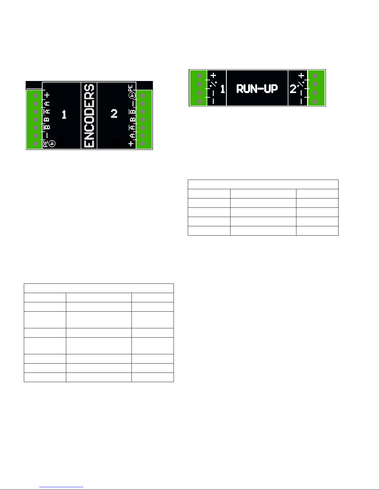
Wire Pattern Control Board
Encoder Installation
(PC-8e only)
1. Connect up to two encoders to monitor line speed.
NOTE: Line 1 and line 2 on the ADM.
NOTE: Encoder type must be quadrature differential
line driver (RS422). Scaling is entered in the
encoder setup screen using the live calibration feature.
NOTE: Some encoders have Z and Z’ connections.
These are not used and do not need to be connected.
Run Up Installation (PC-8e only)
1. Connect up to two “I/P” or “V/P” run-up air pressure
regulators to vary pump pressure based on line
speed. Hardware automatically detects whether an
I2P or V2P is connected.
NOTE: Pressure vs. line speed settings are entered
on the run-up setup screen. See Run Up Control,
page 42.
Standard Wire Colors
Terminal Function M12 Cable
Plus (+) 24V Supply Brown
% Output to run-up Black
Minus (-) Return Blue
Minus (-) Return White
NOTE: Encoder direction can be reversed by swapping A and A’ with B and B’. Do this is the line speed
reads negative on the ADM.
Graco Encoder Wiring Diagram
Terminal Function Wire Color
Plus 15V Supply Red
A Phase A signal
(RS422)
A’ Phase A signal return White
B Phase B signal
(RS422)
B’ Phase B signal return Green
Minus (-) Return Blue
PE Shield Bare
Brown
Yellow
20 334784G
 Loading...