

Operation, Repair and Parts
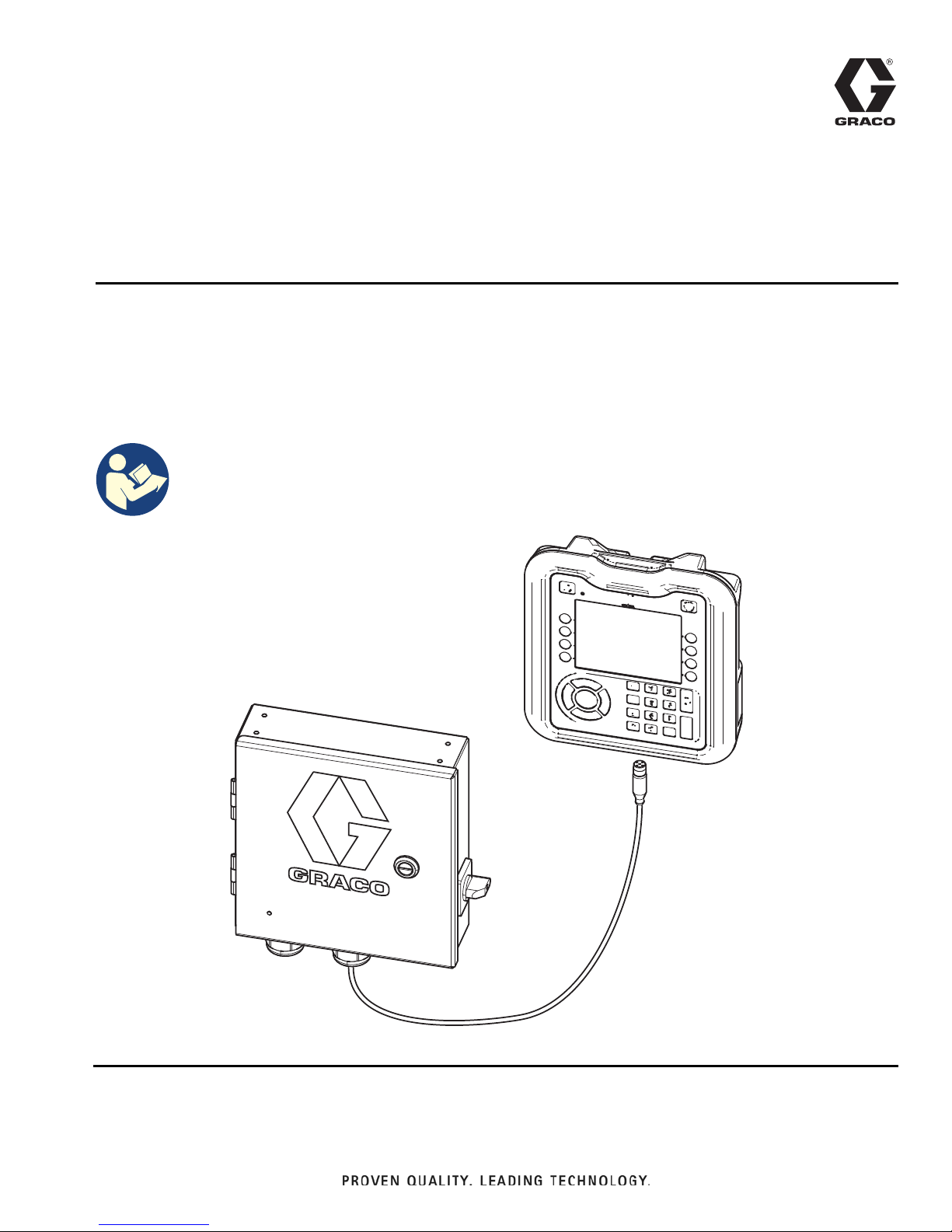
InvisiPac®
334784G
Pattern Controller
To control fluid dispense valves of adhesive supply equipment. For professional use only.
Not approved for use in explosive atmospheres or hazardous locations.
See page 3 for model information and Agency approvals.
Important Safety Instructions
Read all warnings and instructions in this manual
and related manuals. Save these instructions.
EN
WLD

Contents
Models . . . . . . . . . . . . . . . . . . . . . . . . . . . . . . . . . . . 3
Approvals . . . . . . . . . . . . . . . . . . . . . . . . . . . . . . . . . 3
Related Manuals . . . . . . . . . . . . . . . . . . . . . . . . . . . 3
Warnings . . . . . . . . . . . . . . . . . . . . . . . . . . . . . . . . . 4
Overview . . . . . . . . . . . . . . . . . . . . . . . . . . . . . . . . . . 7
Component Identification (Internal Models - HM25c)
8
Component Identification
(Internal Models - HM25 and HM50) . . . . . . . . . 9
Component Identification (External Models) . . . 10
Installation - Internal Models (HM25c) . . . . . . . . . 11
Connect Pattern Control Board . . . . . . . . . . . . . 11
Installation - Internal Models (HM25 and HM50) . 12
Connect Pattern Control Board . . . . . . . . . . . . . 12
Connect Power Supply and Advanced Display
Module . . . . . . . . . . . . . . . . . . . . . . . . . . . . 13
Install Control Board into InvisiPac System . . . 14
Installation - External Models . . . . . . . . . . . . . . . . 15
Mounting . . . . . . . . . . . . . . . . . . . . . . . . . . . . . . 15
Connect Advanced Display Module (ADM) . . . . 15
Connect Pattern Control Board . . . . . . . . . . . . . 16
Connect Electrical Cord . . . . . . . . . . . . . . . . . . 17
Wire Pattern Control Board . . . . . . . . . . . . . . . . . 18
Valve Installation . . . . . . . . . . . . . . . . . . . . . . . . 18
Trigger Installation . . . . . . . . . . . . . . . . . . . . . . 18
PLC Inputs and Outputs Installation (optional) . 19
Encoder Installation
(PC-8e only) . . . . . . . . . . . . . . . . . . . . . . . . 20
Run Up Installation (PC-8e only) . . . . . . . . . . . 20
Initial Startup . . . . . . . . . . . . . . . . . . . . . . . . . . . . . 21
Software Update . . . . . . . . . . . . . . . . . . . . . . . . 21
Key Token . . . . . . . . . . . . . . . . . . . . . . . . . . . . . 21
Screens . . . . . . . . . . . . . . . . . . . . . . . . . . . . . . . . . . 22
Screen Maps . . . . . . . . . . . . . . . . . . . . . . . . . . . 22
HMI Interface . . . . . . . . . . . . . . . . . . . . . . . . . . 23
PC Screens . . . . . . . . . . . . . . . . . . . . . . . . . . . . 24
Advanced Screens . . . . . . . . . . . . . . . . . . . . . . 35
Stitching . . . . . . . . . . . . . . . . . . . . . . . . . . . . . . . . . 37
Random Length Bead Mode . . . . . . . . . . . . . . . . . 38
Mirror Mode . . . . . . . . . . . . . . . . . . . . . . . . . . . . . . 39
Calibration . . . . . . . . . . . . . . . . . . . . . . . . . . . . . . . 40
Gun Compensation (optional) . . . . . . . . . . . . . . 40
Line Speed . . . . . . . . . . . . . . . . . . . . . . . . . . . . 41
Run Up Control (PC-8e only) . . . . . . . . . . . . . . . 42
Modulated Bead (PC-8e Only) . . . . . . . . . . . . . 43
Verification . . . . . . . . . . . . . . . . . . . . . . . . . . . . . . . 44
Valves . . . . . . . . . . . . . . . . . . . . . . . . . . . . . . . . 44
Triggers . . . . . . . . . . . . . . . . . . . . . . . . . . . . . . . 44
Encoder . . . . . . . . . . . . . . . . . . . . . . . . . . . . . . . 44
Run Up Control . . . . . . . . . . . . . . . . . . . . . . . . . 44
PLC Inputs . . . . . . . . . . . . . . . . . . . . . . . . . . . . . 44
Troubleshooting . . . . . . . . . . . . . . . . . . . . . . . . . . . 45
Error Codes . . . . . . . . . . . . . . . . . . . . . . . . . . . . 45
Display . . . . . . . . . . . . . . . . . . . . . . . . . . . . . . . . 46
Pattern . . . . . . . . . . . . . . . . . . . . . . . . . . . . . . . . 46
Valve . . . . . . . . . . . . . . . . . . . . . . . . . . . . . . . . . 47
Trigger . . . . . . . . . . . . . . . . . . . . . . . . . . . . . . . . 47
Encoder . . . . . . . . . . . . . . . . . . . . . . . . . . . . . . . 47
Run Up . . . . . . . . . . . . . . . . . . . . . . . . . . . . . . . 48
PLC Inputs and Outputs . . . . . . . . . . . . . . . . . . 48
Software Update Procedure . . . . . . . . . . . . . . . . . 49
USB Download . . . . . . . . . . . . . . . . . . . . . . . . . . . . 50
Download Procedure . . . . . . . . . . . . . . . . . . . . . 50
Accessing Files . . . . . . . . . . . . . . . . . . . . . . . . . 50
USB Logs . . . . . . . . . . . . . . . . . . . . . . . . . . . . . 50
Parts . . . . . . . . . . . . . . . . . . . . . . . . . . . . . . . . . . . . 51
External Models . . . . . . . . . . . . . . . . . . . . . . . . . 51
Internal Models (HM25c) . . . . . . . . . . . . . . . . . . . . 53
Internal Models (HM25 and HM50) . . . . . . . . . . 54
Kits . . . . . . . . . . . . . . . . . . . . . . . . . . . . . . . . . . . 55
Wiring Diagrams . . . . . . . . . . . . . . . . . . . . . . . . . . 58
Internal Pattern Controller (HM25 and HM50
Systems with AWB) . . . . . . . . . . . . . . . . . . 58
Internal Pattern Controller (HM25 Systems with DIN
Rail) . . . . . . . . . . . . . . . . . . . . . . . . . . . . . . . 59
External Models . . . . . . . . . . . . . . . . . . . . . . . . . 60
Dimensioned Drawings . . . . . . . . . . . . . . . . . . . . . 61
Technical Specifications . . . . . . . . . . . . . . . . . . . . 64
Notes . . . . . . . . . . . . . . . . . . . . . . . . . . . . . . . . . . . . 65
Graco Standard Warranty . . . . . . . . . . . . . . . . . . . 66
2 334784G

Models
Internal Models (HM25c)
Used to upgrade InvisiPac HM25c systems to include pattern control.
Part Type Description Contents
25M526 PC-8* Time or distance mode, no encoder Pattern controller
* Order kit 17F712 to upgrade to PC-8e.
Internal Models (HM25 and HM50)
Used to upgrade InvisiPac HM25 and HM50 systems to include pattern control.
Part Type Description Contents
24X640 PC-8 Time or distance mode, no encoder Internal pattern controller
24X641 PC-8e Time or distance mode, with or without encoder
Run up control (optional)
Internal pattern controller
Key token for encoder and run up
Models
External Integrated Models
Used to connect a separate pattern control enclosure to an InvisiPac system (compatible with all InvisiPac systems)
Part Type Description Contents
24X523 PC-8 Time or distance mode, no encoder Pattern controller
24X524 PC-8e Time or distance mode, with or without encoder
Run up control (optional)
Pattern controller
Key token for encoder and run up
External Stand Alone Models
Used for applications without an InvisiPac system
Part Type Description Contents
24X525 PC-8 Time or distance mode, no encoder Pattern controller
Advanced display module
24X526 PC-8e Time or distance mode, with or without encoder
Run up control (optional)
Pattern controller
Advanced display module
Key token for encoder and run up
Approvals Related Manuals
Part Description Approvals
127971 External pattern controller CE, ETL, cETL
24W293 Internal pattern controller
(HM25c)
24X521 Internal pattern controller
(HM25 and HM50)
24E451 Advanced display module CE, ETL, cETL
CE, ETL, cETL
CE, ETL, cETL
Part Description
3A4938
333347
334934 Run Up Pressure Kit
InvisiPac HM25c Tank-Free
Delivery System
InvisiPac HM25 and HM50 Tank-Free
Hot Melt Delivery System
™
Hot Melt
™
334784G 3
Warnings
WARNING
Warnings
The following warnings are for the setup, use, grounding, maintenance, and repair of this equipment. The exclamation point symbol alerts you to a general warning and the hazard symbols refer to procedure-specific risks. When
these symbols appear in the body of this manual or on warning labels, refer back to these Warnings. Product-specific
hazard symbols and warnings not covered in this section may appear throughout the body of this manual where
applicable.
ELECTRIC SHOCK HAZARD
This equipment must be grounded. Improper grounding, setup, or usage of the system can cause
electric shock.
• Turn off and disconnect power at main switch before disconnecting any cables and before
servicing or installing equipment.
• Connect only to grounded power source.
• All electrical wiring must be done by a qualified electrician and comply with all local codes and
regulations.
EQUIPMENT MISUSE HAZARD
Misuse can cause death or serious injury.
• Do not operate the unit when fatigued or under the influence of drugs or alcohol.
• Do not exceed the maximum working pressure or temperature rating of the lowest rated system
component. See Technical Specifications in all equipment manuals.
• Use fluids and solvents that are compatible with equipment wetted parts. See Technical Specifi-
cations in all equipment manuals. Read fluid and solvent manufacturer’s warnings. For complete
information about your material, request MSDS from distributor or retailer.
• Do not leave the work area while equipment is energized or under pressure.
• Turn off all equipment and follow the Pressure Relief Procedure when equipment is not in use.
• Check equipment daily. Repair or replace worn or damaged parts immediately with genuine
• manufacturer’s replacement parts only.
• Do not alter or modify equipment. Alterations or modifications may void agency approvals and create safety hazards.
• Make sure all equipment is rated and approved for the environment in which you are using it.
• Use equipment only for its intended purpose. Call your distributor for information.
• Route hoses and cables away from traffic areas, sharp edges, moving parts, and hot surfaces.
• Do not kink or over bend hoses or use hoses to pull equipment.
• Keep children and animals away from work area.
• Comply with all applicable safety regulations.
BURN HAZARD
Equipment surfaces and fluid that is heated can become very hot during operation. To avoid severe
burns.
• Do not touch hot fluid or equipment.
4 334784G
Warnings
WARNING
SKIN JECTION HAZARD
High-pressure fluid from dispensing device, hose leaks, or ruptured components will pierce skin. This
may look like just a cut, but it is a serious injury that can result in amputation. Get immediate surgi-
cal treatment.
• Do not point dispensing device at anyone or at any part of the body.
• Do not put your hand over the fluid outlet.
• Do not stop or deflect leaks with your hand, body, glove, or rag.
• Follow the Pressure Relief Procedure when you stop dispensing and before cleaning, checking,
or servicing equipment.
• Tighten all fluid connections before operating the equipment.
• Check hoses and couplings daily. Replace worn or damaged parts immediately.
MOVING PARTS HAZARD
Moving parts can pinch, cut or amputate fingers and other body parts.
• Keep clear of moving parts.
• Do not operate equipment with protective guards or covers removed.
• Equipment can start without warning. Before checking, moving, or servicing equipment, follow the
Pressure Relief Procedure and disconnect all power sources.
FIRE AND EXPLOSION HAZARD
Flammable fumes, such as solvent and paint fumes, in work area can ignite or explode. To help prevent fire and explosion:
• Do not use solvent-based adhesives that can create an explosive atmosphere when processed.
• Use equipment only in well-ventilated area.
• Eliminate all ignition sources; such as pilot lights, cigarettes, portable electric lamps, and plastic
drop cloths (potential static sparking).
• Keep work area free of debris, including solvent, rags and gasoline.
• Do not plug or unplug power cords, or turn power or light switches on or off when flammable fumes
are present.
• Ground all equipment in the work area. See Grounding instructions.
• Use only grounded hoses.
• Stop operation immediately if static sparking occurs or you feel a shock. Do not use equipment
until you identify and correct the problem.
• Keep a working fire extinguisher in the work area.
334784G 5
Warnings
WARNING
TOXIC FLUID OR FUMES HAZARD
Toxic fluids or fumes can cause serious injury or death if splashed in the eyes or on skin, inhaled, or
swallowed.
• Read Safety Data Sheets (SDSs) to know the specific hazards of the fluids you are using.
• Store hazardous fluid in approved containers, and dispose of it according to applicable guidelines.
PERSONAL PROTECTIVE EQUIPMENT
Wear appropriate protective equipment when in the work area to help prevent serious injury,
including eye injury, hearing loss, inhalation of toxic fumes, and burns. Protective equipment includes
but is not limited to:
• Protective eyewear, and hearing protection.
• Respirators, protective clothing, and gloves as recommended by the fluid and solvent
manufacturer.
PRESSURIZED ALUMINUM PARTS HAZARD
Use of fluids that are incompatible with aluminum in pressurized equipment can cause serious
chemical reaction and equipment rupture. Failure to follow this warning can result in death, serious
injury, or property damage.
• Do not use 1,1,1-trichloroethane, methylene chloride, other halogenated hydrocarbon solvents or
fluids containing such solvents.
• Do not use chlorine bleach.
• Many other fluids may contain chemicals that can react with aluminum. Contact your material
supplier for compatibility.
6 334784G

Overview
Overview
InvisiPac pattern control systems can be integrated with InvisiPac systems or stand alone with any other equipment.
For all installations, the advanced display module (ADM) is used to make programming easy.
PC-8 controllers operate in time or distance mode without an encoder. Up to 8 guns and 4 independent triggers are
supported.
PC-8e controllers include the same features as PC-8 with the addition of distance based control using an encoder,
and run up control using an I/P or V/P pressure regulator.
Features of the PC-8 and PC-8e:
Feature
Gun outputs
Trigger inputs
Encoder
Run up control
Program storage
PLC enable / disable
PLC alarm output
PLC program select
Password protection
Integrated power supply
For more information, see Technical Specifications,
page 64.
8
4
2 (PC-8e only)
2 (PC-8e only)
50
Yes
Yes
Yes
Yes
Yes
Details
334784G 7
Component Identification (Internal Models - HM25c)
/
.
-
+
WLE
6
3
&
7
Installed onto InvisiPac System
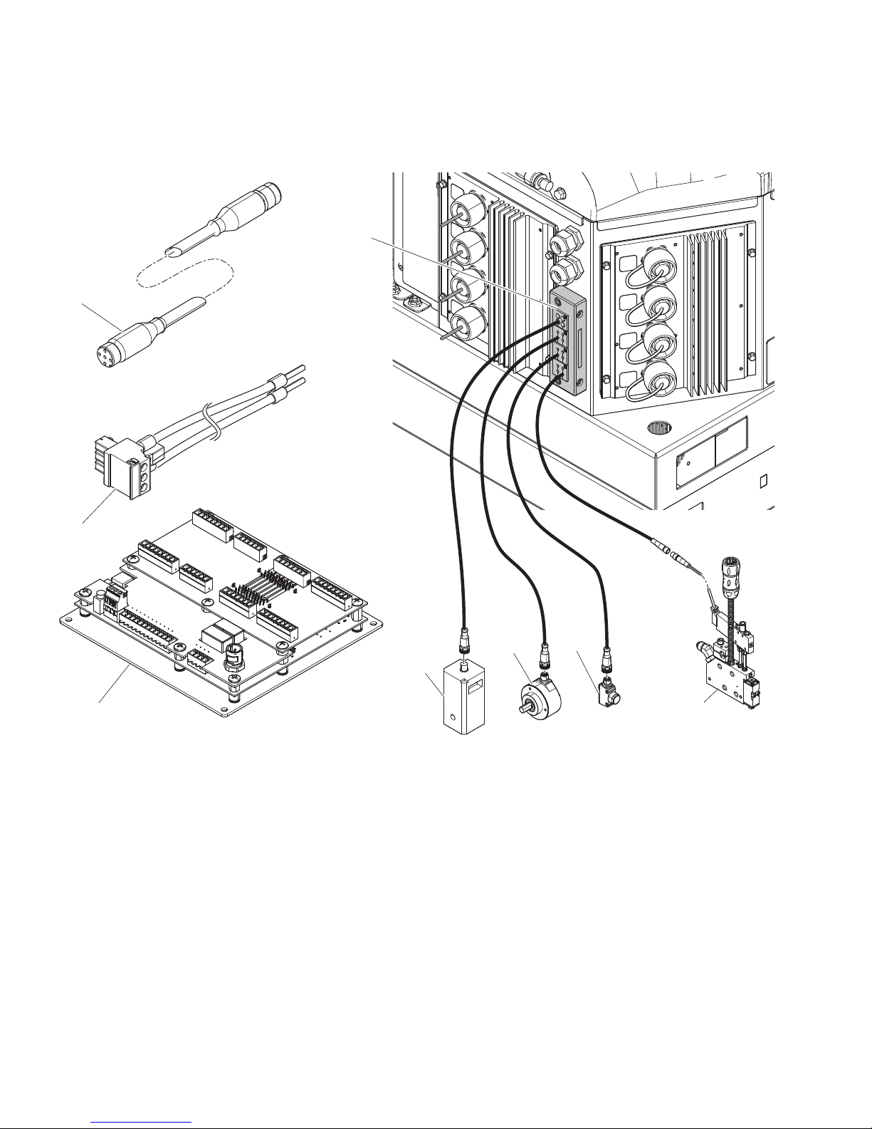
Component Identification (Internal Models - HM25c)
Key
C Communication cable
HValve
J Trigger
K Encoder
Key
L Run up
P Power harness
S Control board
T Cord grip
8 334784G
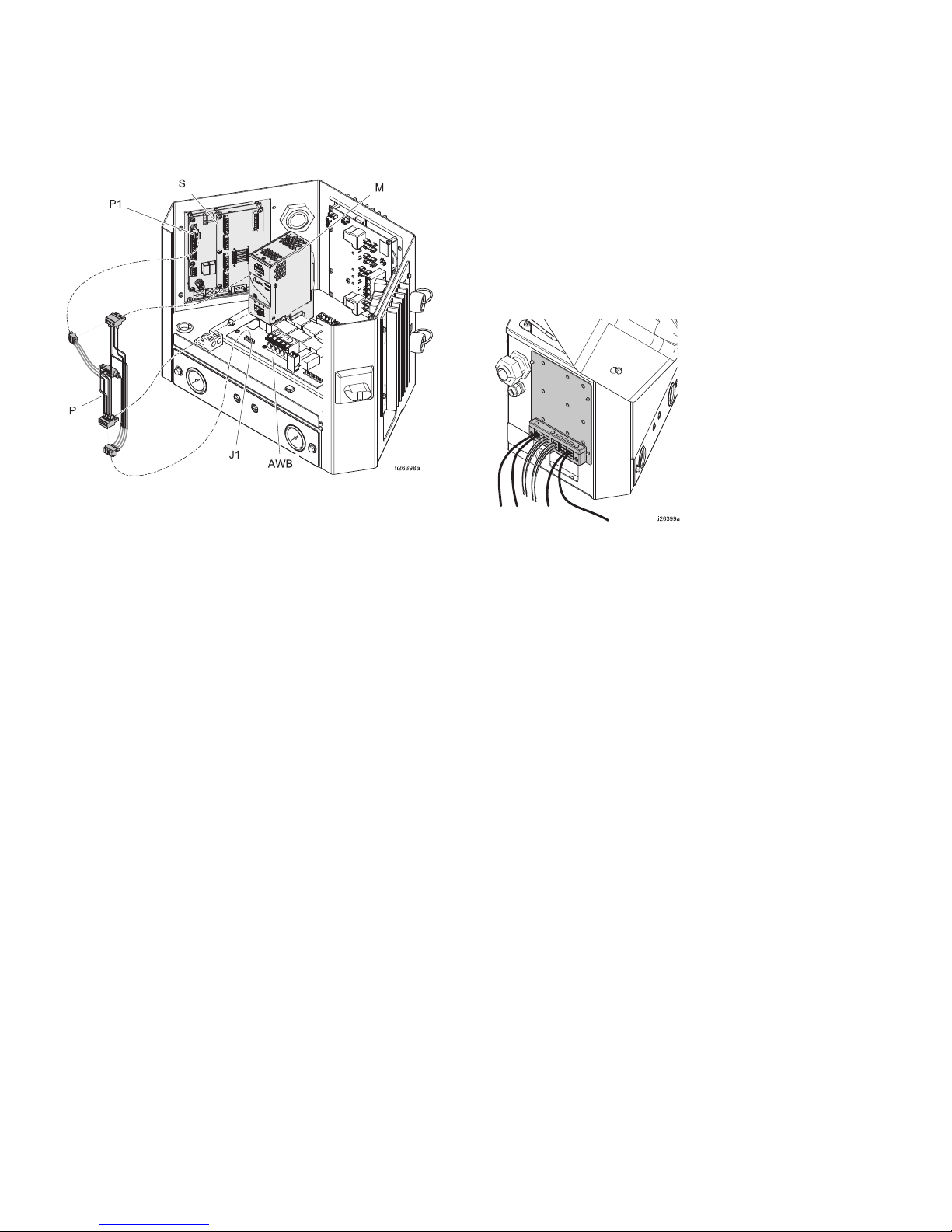
Component Identification (Internal Models - HM25 and HM50)
Installed onto InvisiPac System
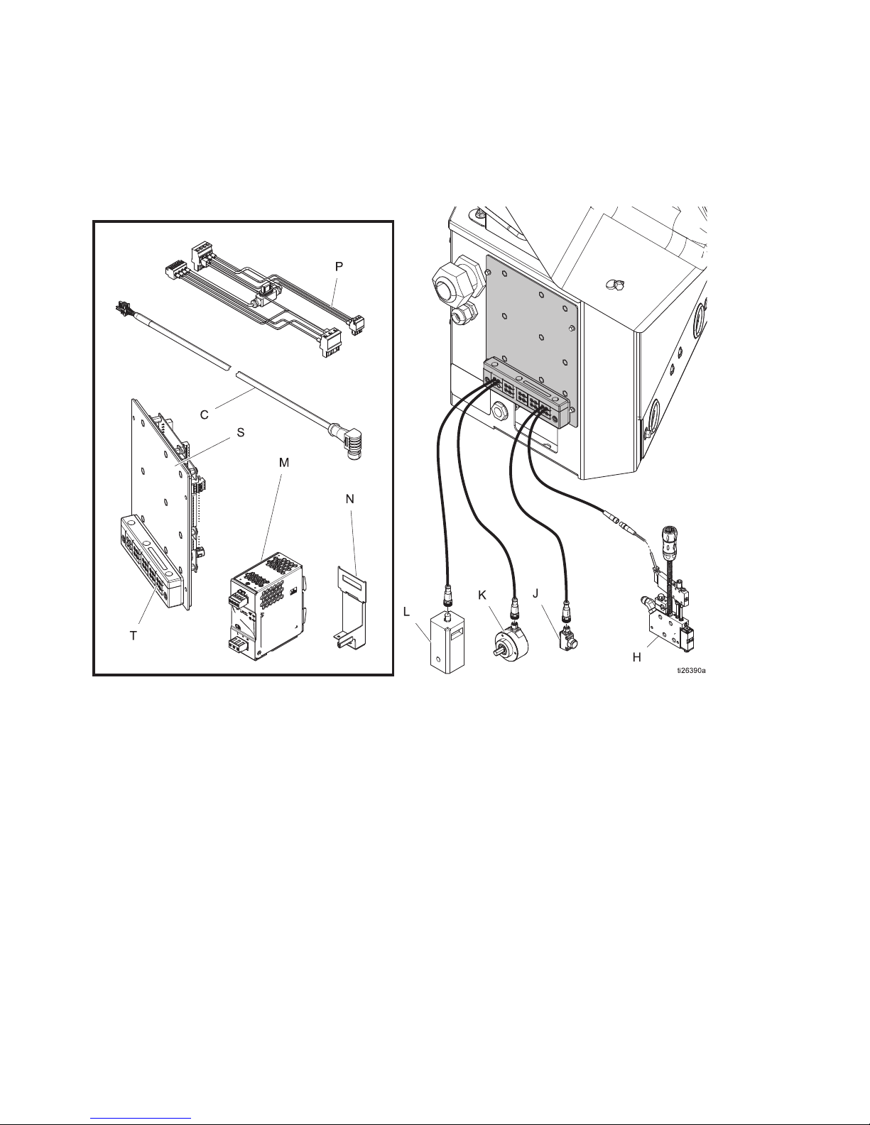
Component Identification
(Internal Models - HM25 and HM50)
Key
C
H
J
K
L
334784G 9
Communication cable
Valve
Trigger
Encoder
Run Up
Key
M
N
P
S
T
Power supply
Power supply bracket
Power harness
Control board
Cord grip

Component Identification (External Models)
7
7
7
3
6
%
'
&
1
/
.
-
+
$
0
WLE
(
Component Identification (External Models)
Key
A
B
C
D
E
H
J
Pattern controller
Power switch
Communication cable
ADM
USB port
Valve
Trigger
Key
K
L
M
N
P
S
T
Encoder
Run up
Inside view of pattern controller
Customer power board (not included)
Ground terminal
Control board
Cord grips (I/O x2 power)
10 334784G
Installation - Internal Models (HM25c)
WLD
0
WLD
7
Installation - Internal Models (HM25c)
Connect Pattern Control Board
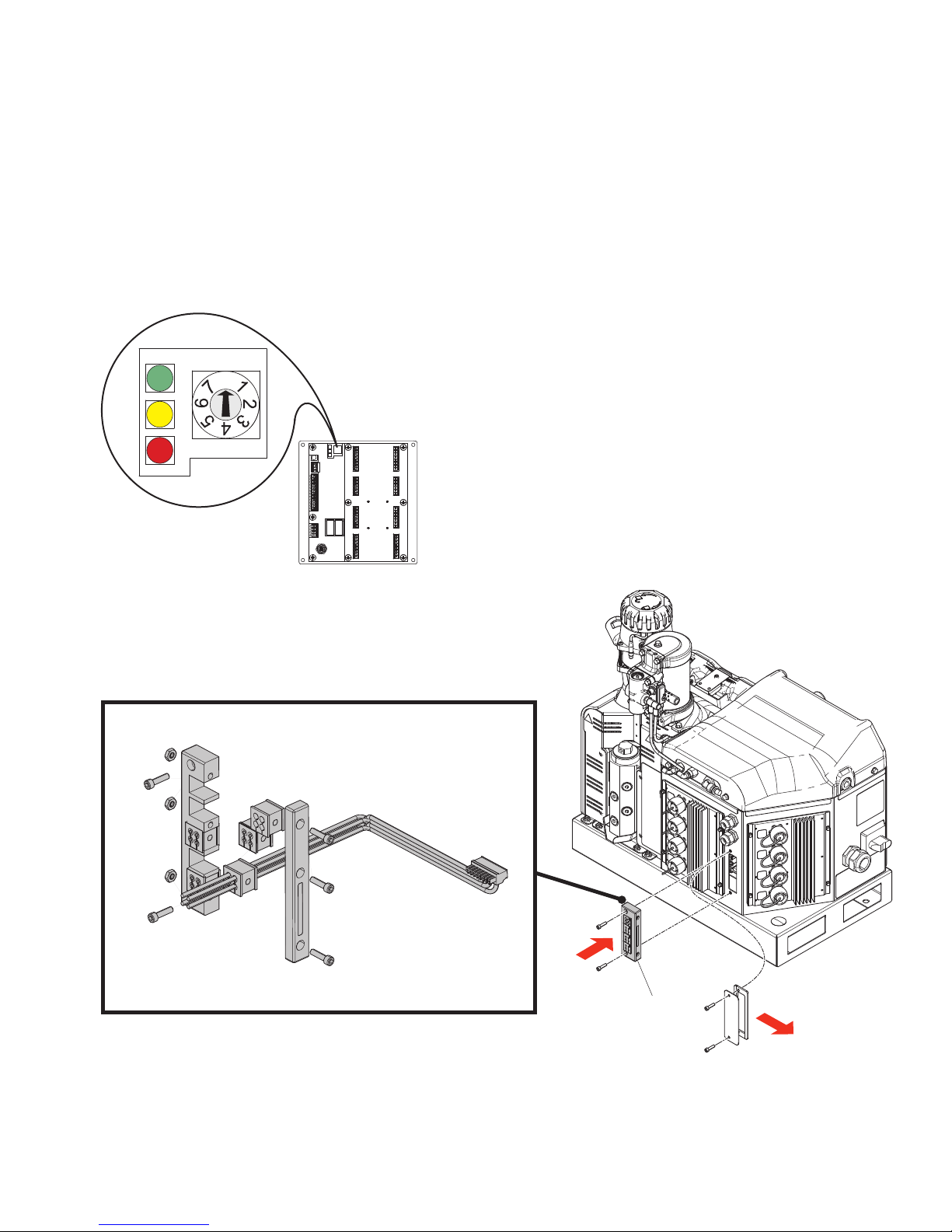
1. Set pattern control system type selector switch to 0.
NOTE: The system must be powered off for a
change in system type to have an effect.
2. Remove cord grip assembly (T) from back of InvisiPac system and remove inserts. Inserts with grip
tightly on most M8 and M12 cables and expand and
compress to accept cables larger than the apparent
hole size.
3. Install valve signal wires, trigger signal wires, PLC
wires (optional). See Wire Pattern Control Board,
page 18.
4. Route cables through the opening in the back of the
InvisiPac enclosure as shown.
5. Apply cord grip inserts over cables and replace into
frame. Replace frame onto back of InvisiPac enclosure.
6. Remove excess slack from the cables but do not
pull tight. Tighten cord grip frame on inserts to
secure.
334784G 11

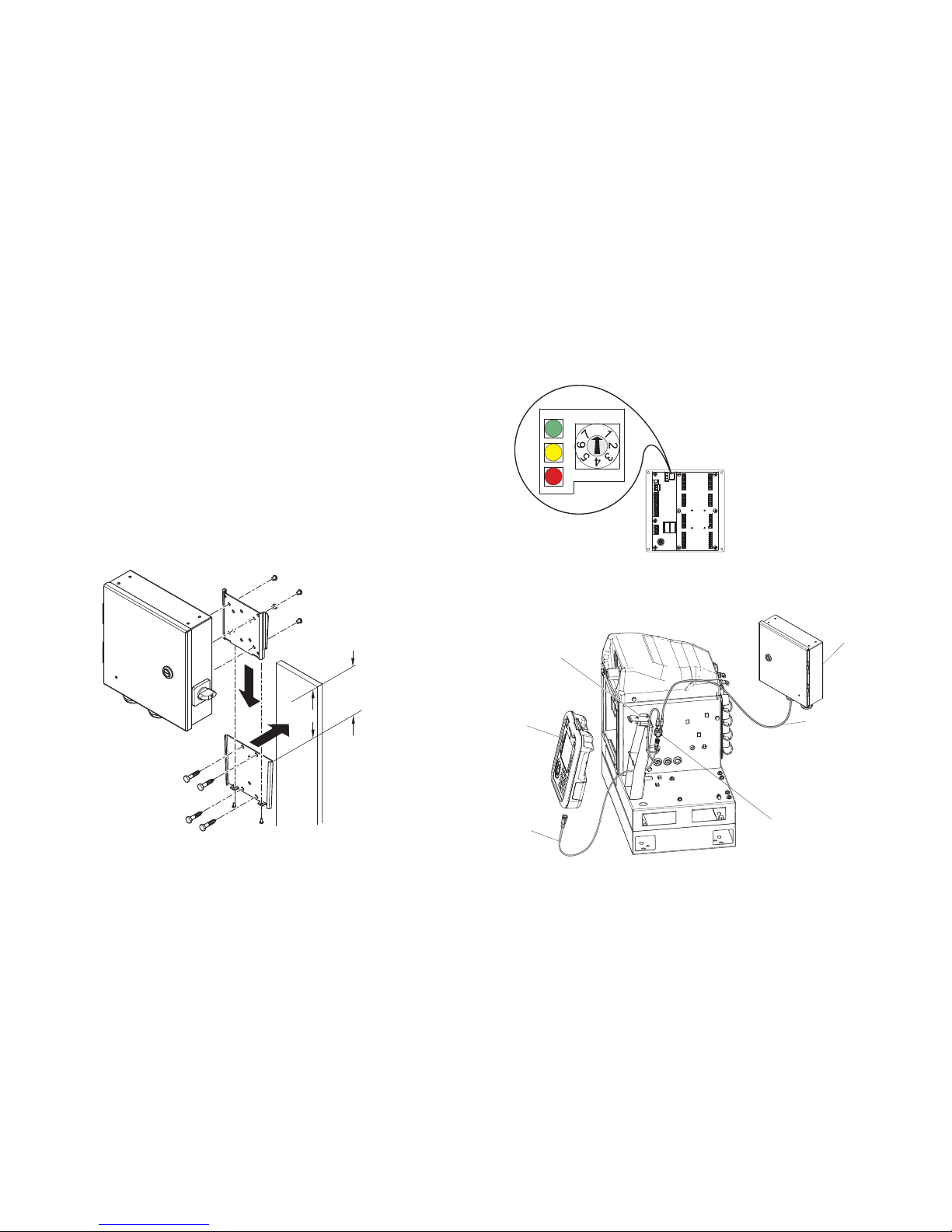
Installation - Internal Models (HM25 and HM50)
0
Installation - Internal Models (HM25 and HM50)
Connect Pattern Control Board
1. Set pattern control system type selector switch to 0.
NOTE: The system must be powered off for a
change in system type to have an effect.
WLD
2. Remove cord grip assembly (T) from pattern control
board (S) and remove inserts. Inserts will grip tightly
on most M8 and M12 cables and will expand and
compress to accept cables larger than the apparent
hole size.
3. Install valve signal wires, trigger signal wires, PLC
wires (optional) and encoder and run up wires
(PC-8e only). See Wire Pattern Control Board,
page 18.
4. Route cables through the opening in the pattern
control board back panel as shown.
5. Apply cord grip inserts over cables and replace into
frame. Replace frame onto pattern control panel.
6. Remove excess slack from cables but do not pull
tight. Tighten cord grip frame on inserts to secure.
12 334784G
Installation - Internal Models (HM25 and HM50)
Connect Power Supply and Advanced Display Module
NOTE: If the internal pattern controller is being installed
into a first generation HM25 with DIN rail writing, additional connections must be made.
Install Kit 24Y171 has the necessary components and
instructions to perform this installation. See Kits, page
55.
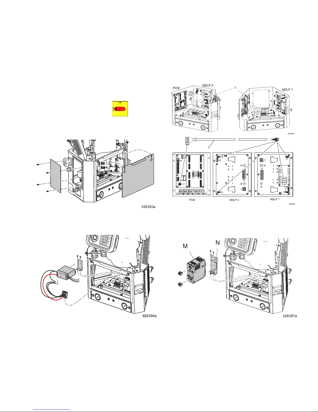
1. Turn main power switch OFF.
2. Remove panel door, then remove blanking plate
from left-hand side of system electrical enclosure.
4. Connect communication cable (C) to open J3 connector (or J6, if J3 is used) on MZLP board. If connecting to MZLP #2, loop extra cable length along
edge of electrical enclosure.
3. Remove connector from AWB terminal pins J1 and
remove the power supply and harness from mounting bracket. Unscrew mounting bracket from AWB.
5. Remove blue connectors from terminals of power
supply W and discard or set aside. Install new
power supply bracket (N) onto AWB and clip new
power supply (M) into place.
334784G 13
Installation - Internal Models (HM25 and HM50)
6. Connect power harness (P) to AWB terminal pins J1
and the input and output terminals of power supply.
Install Control Board into
InvisiPac System
1. Mount board into open space on left-hand side of
electrical enclosure. Use serrated-flange screws.
2. Connect power harness to power control board terminal P1, and connect communication cable to pattern control board terminal P4.
3. Replace system electrical enclosure door.
14 334784G
Installation - External Models
WLF
13 in (330.2 mm)
Clearance
WLD
0
$
'
%
Installation - External Models
Mounting
The pattern controller and ADM can be mounted using
the included VESA-compatible brackets and mounting
software.
1. Unscrew the two lower screws to uncouple the
“wall” portion of the bracket.
2. Securely mount the bracket in the desired location.
3. Slide the controller onto the bracket and tighten the
two screws for permanent fastening.
ALTERNATIVE METHOD: Remove mounting hardware
and mount directly to any surface.
NOTE: Make sure at least 13 in. of clearance is available above the top of the mounting bracket in order to
slide the enclosure in and out of the wall mount.
Connect Advanced Display
Module (ADM)
Integrate with InvisiPac HM25c
1. Set pattern control system type selector switch to 0.
NOTE: The system must be powered off for a
change in system type to have an effect.
2. Disconnect the CAN cable from the ADM (D) and
connect it to one of the male ends of the splitter (2).
NOTE: To make repairing the system easier, locate the
system so that it is easily accessible and has sufficient
lighting.
334784G 15
WLE
3. Connect the CAN cable from the pattern controller
enclosure (A) to the other male end of the splitter
(2).
4. Connect the male end of the short CAN cable contained in the pattern controller kit (3) to the female
end of the splitter (2).
5. Connect female end of the short CAN cable (3) to
the ADM.
6. Use zip ties to attach the CAN cables and splitter to
the ADM bracket (B).
Installation - External Models
WLD
0
WLD
0
&
WLD
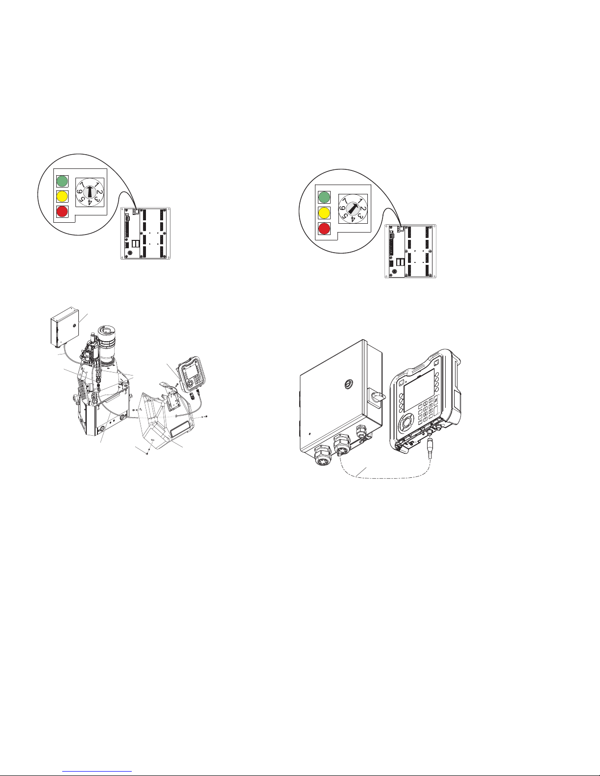
Integrate with InvisiPac (HM25 or HM50)
1. Set pattern control system type selector switch to 0.
NOTE: The system must be powered off for a
change in system type to have an effect.
2. Disconnect the CAN cable from the ADM (D), push
the cable through the plastic shroud (B), the remove
the shroud from the system.
$
Stand Alone
1. Set the pattern control system type selector switch
to 1.
NOTE: The system must be powered off for a
change in system type to have an effect.
2. Mount the ADM using the provided bracket
3. Connect the CAN cable (C) between the pattern
controller and the ADM
&
%
WLD
3. Connect the CAN cable from the ADM (D) to one of
the male ends of the splitter (2).
4. Connect the CAN cable from the pattern controller
(A) to the other male end of the splitter (2).
5. Connect the male end of the short CAN cable contained in pattern controller kit (3) to the female end
of the splitter.
6. Push the free end of the short CAN cable (3)
through the shroud and connect the female end to
the ADM.
7. Use zip ties (4) to attach the CAN cable bundle to
the other vertical bundle of cables.
Connect Pattern Control Board
See Wire Pattern Control Board, page 18.
1. Install triggers and valves
2. Install PLC inputs and outputs (optional)
3. Install encoder (PC-8e only)
4. Install run up (optional, PC-8e only)
16 334784G
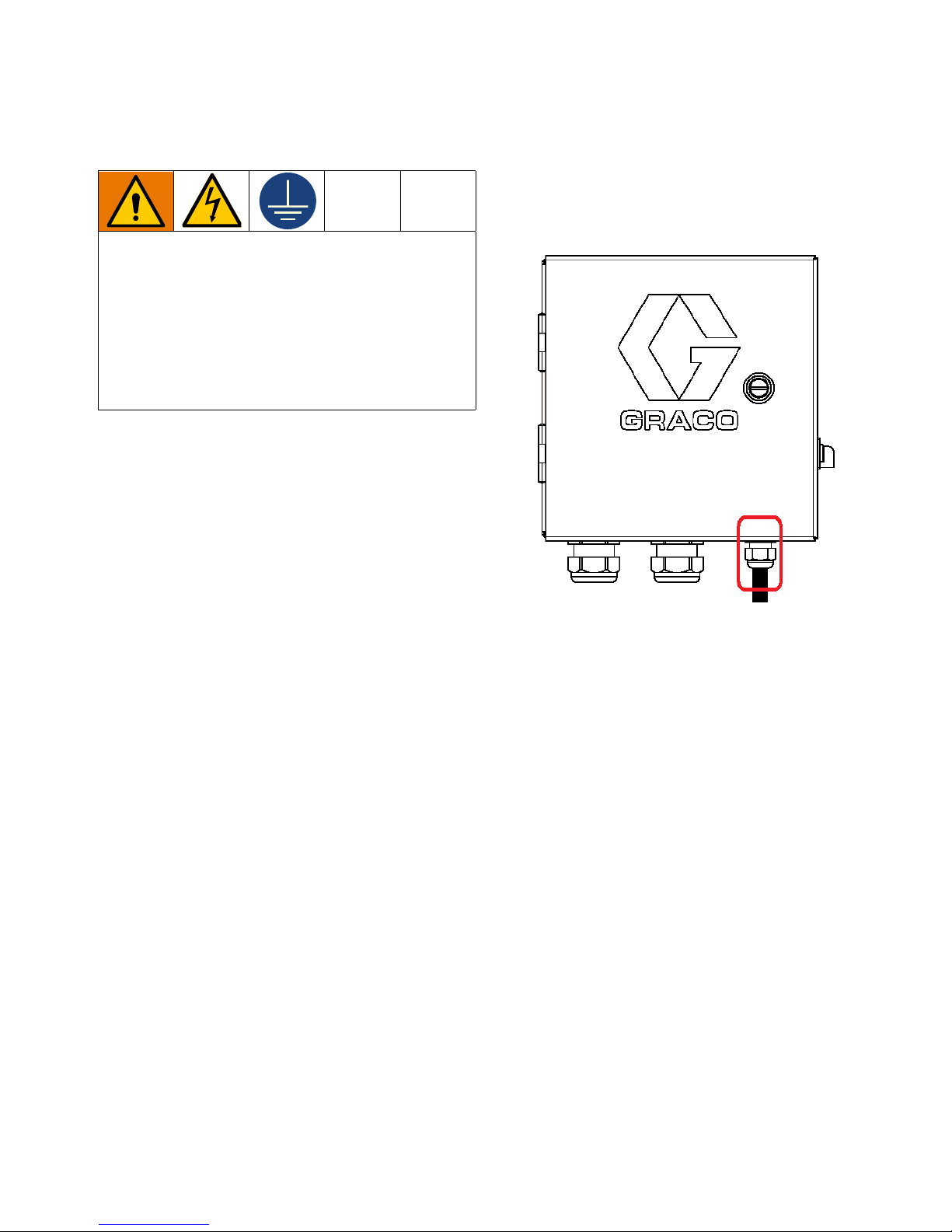
Connect Electrical Cord
Improper wiring may cause electric shock or other
serious injury if work is not performed properly.
Have a qualified electrician perform any electrical
work. Be sure your installation complies with all
National, State, and Local safety and fire codes.
The equipment must be grounded to reduce the
risk of electric shock. Improper grounding can
cause electric shock. Grounding provides an
escape wire for the electric current.
The pattern controller system is equipped with a ground
terminal. Have a qualified electrician ground the system
using this terminal.
Electrical power enters through the smaller cord grip on
the right side of the enclosure (see figure). The power
cord can be further secured inside the enclosure with
the provided zip-tie and tie mount.
Installation - External Models
2. Connect earth ground to the grounding terminal.
3. Verify that the cord grip securely tightens around the
power cord. Use a wrench to tighten, if necessary.
1. Install power wires (L1/L2 or L/N) into terminals 2
and 4 on the disconnect switch. The switch accepts
solid or stranded 12 AWG and 14 AWG wire. For
ratings, see Technical Specifications, page 64.
NOTE: The power switch housing can be removed
for easy wiring using the red tab on top of the
switch.
334784G 17
Wire Pattern Control Board
Wire Pattern Control Board
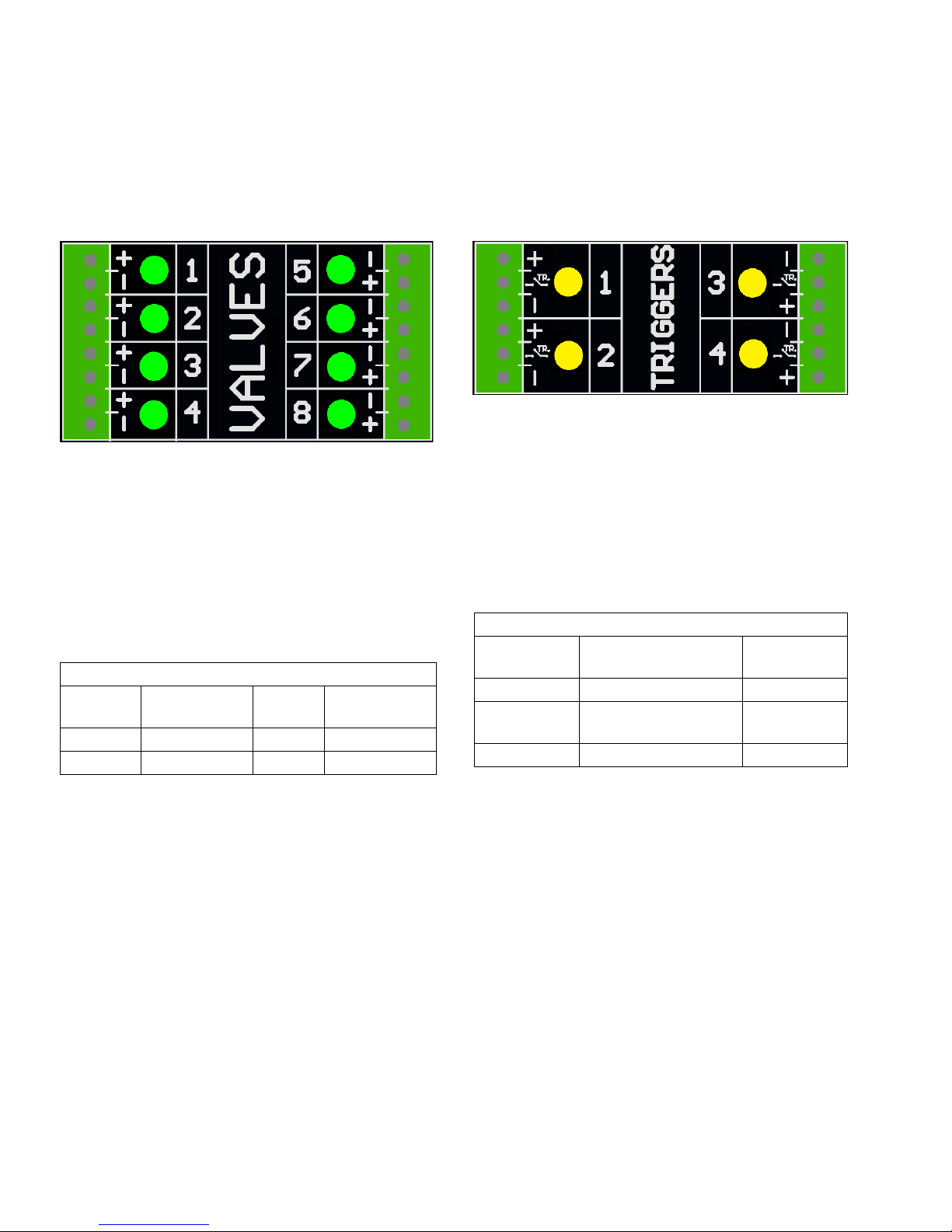
Valve Installation
1. Connect up to 8 valves.
NOTE: Control voltage is 24 VDC with a limit of 1
amp per output and 6 amps total.
NOTE: Green LEDs indicate the status of each
valve.
NOTE: DIN cable black wires are labeled 1 and 2. 1
is plus and 2 is minus.
Standard Wiring Colors
Terminal
Cable
Plus (+) 24V Supply Brown Black 1
Minus (-) Return Blue Black 2
Function M8
Cable
DIN Cable
Trigger Installation
1. Connect up to 4 NPN, PNP, or dry contact triggers.
NOTE: Supplied voltage (+) is 24 VDC
2. Connect the two wires between TR and minus (-) to
install a dry contact.
NOTE: Yellow LEDs indicate the status of each trigger. Polarity can be inverted if needed. See Trigger
Setup, page 31.
Standard Wiring Colors
Terminal Function M8 or M12
Cable
Plus (+) 24V Supply Brown
TR NPN, PNP, or dry con-
tact
Minus (-) Return (or dry contact) Blue
Black or white
18 334784G

PLC Inputs and Outputs Installation (optional)
PCM PLC Output
Customer Input
24 VDC, 240VAC, 2A
Max
To Customer Input
PCM PLC Input
Customer Output
Vin (no polarity)
30 VDC Max
Dry Contact
(customer supplied)
Customer
PCM
(Jumper Wire)
“+”
(24 VDC)
“-”
(GND)
Functions:
Type Function Description
Input ENABLE Turns the controller on and off (rising edge enables, falling edge disables).
Integrated systems: Turn the heat on/off using the InvisiPac PLC input
(instead of this input). The pattern controller will be turned on by the InvisiPac
system once the InvisiPac goes inactive.
DISABLE Disables the pattern controller (pull high to disable)
NOTE: DISABLE polarity can be changed with the invert disable input setting.
See General Setup (Screen 4), page 32.
PROGRAM
SELECT
Output ALARM 1 Relay opens for active alarm(s) on Line 1
ALARM 2 Relay opens for active alarm(s) on Line 2
Specifications
Inputs Outputs
• Bipolar Input • Dry contact output
• Electrically isolated • 0-24 VDC or 0-240 VAC
• 0-30 VDC • 2A max
• Min. 10 VDC to assert
• Sinks 10 mA at 24 VDC
Bits select a program to run (1-15) i.e. 1010 selects program #10
NOTE: 0000 disables PLC selection (local program selection ADM)
Wire Pattern Control Board
NOTE: To connect a dry contact signal, route GND to
one terminal and connect 24 VDC signal through the dry
contact to the other terminal (see image below).
334784G 19
Alarms indicated by output relays. See Troubleshooting Error Codes, page 45 for more details.
Code Description
A40P Over-current on accessory
power supply output
A4XP Over-current on communication
cable output
A4_P Over-current on valve output “_”
K4_P Encoder “_” pulse rate exceeds
maximum limit
Wire Pattern Control Board
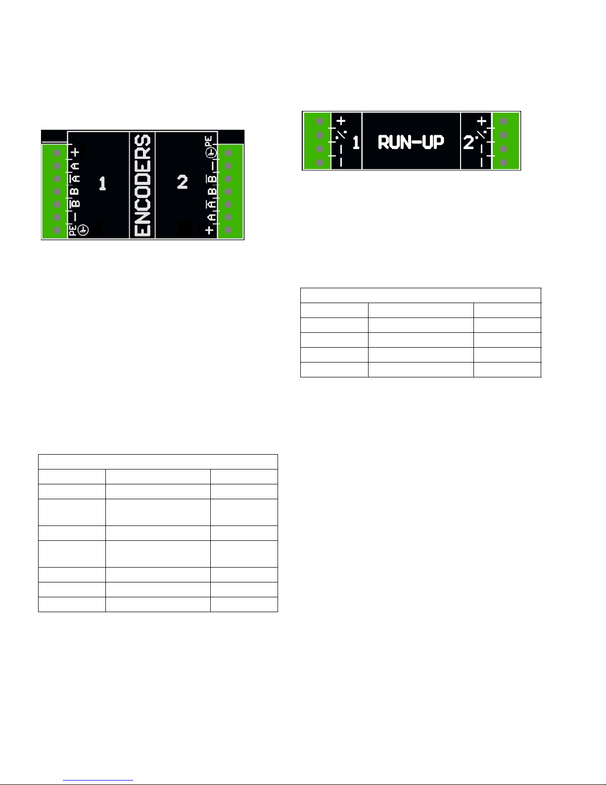
Encoder Installation
(PC-8e only)
1. Connect up to two encoders to monitor line speed.
NOTE: Line 1 and line 2 on the ADM.
NOTE: Encoder type must be quadrature differential
line driver (RS422). Scaling is entered in the
encoder setup screen using the live calibration feature.
NOTE: Some encoders have Z and Z’ connections.
These are not used and do not need to be connected.
Run Up Installation (PC-8e only)
1. Connect up to two “I/P” or “V/P” run-up air pressure
regulators to vary pump pressure based on line
speed. Hardware automatically detects whether an
I2P or V2P is connected.
NOTE: Pressure vs. line speed settings are entered
on the run-up setup screen. See Run Up Control,
page 42.
Standard Wire Colors
Terminal Function M12 Cable
Plus (+) 24V Supply Brown
% Output to run-up Black
Minus (-) Return Blue
Minus (-) Return White
NOTE: Encoder direction can be reversed by swapping A and A’ with B and B’. Do this is the line speed
reads negative on the ADM.
Graco Encoder Wiring Diagram
Terminal Function Wire Color
Plus 15V Supply Red
A Phase A signal
(RS422)
A’ Phase A signal return White
B Phase B signal
(RS422)
B’ Phase B signal return Green
Minus (-) Return Blue
PE Shield Bare
Brown
Yellow
20 334784G

Initial Startup
Initial Startup
Software Update
When integrating into an InvisiPac system, the system
may require a software update in order to be compatible
with the pattern controller. Follow Software Update
Procedure, page 49.
Key Token
For PC-8e models only, a key token is required to
enable encoder and run up use.
1. Remove token access panel on back of ADM.
2. Insert blue key token 24X626 and press firmly into
slot.
3. Replace cover, leaving key token inside.
334784G 21

Screens
PC Home Events ErrorsPC Control
1. Program Storage
- Purge
2. Pattern Definition
- Pattern
Preview
Press to switch between Run and Setup
PC Setup
1. Event Map
2. Line Mode
3. Trigger Setup
4. General
5. Gun Setup
6. Run Up 1
7. Run up 2
Advanced
1. Display
2. Units
3. USB Settings
4. Software
Screens
Navigate through each screen to set up the pattern controller interface.
• Run screens include the home page and pattern definition.
• Setup screens contain configurable settings for each accessory.
Screen Maps
NOTE: On integrated InvisiPac system, additional chapters are present for hot melt HMI.
Run Screens
Setup Screens
22 334784G

HMI Interface
WLLD
1 2 3
4 5 6
7 8 9
0 .
1 2 3
4 5 6
7 8 9
0 .
%&
%'
%(
%)
%*
%+
%$
WLD
Screens
Key Function
BA Controller enable/disable
BC Stop all system processes
BD Defined by icon next to soft key
BE Abort current operation
BF Accept change, acknowledge error,
select item, toggle selected item
BG Toggle between run and setup
screens
BH Navigate within a screen or to a new
screen
NOTICE
To prevent damage to soft key buttons, do not
press the buttons with sharp objects such as pens,
plastic cards, or fingernails.
334784G 23

Screens
A
B
C
D
%
PC Screens
Home
Read-only view of pattern controller inputs and outputs:
1. Status of guns , triggers , and PLC signals.
2. Production rate , and units completed .
3. Material dispensed per product .
A - Gun states
B - Trigger states
C - Line information
D - PLC signals
Icon Name Description
Gun Gun status: active (green), enabled (gray), disabled (crossed out)
Trigger Trigger status: active (bright yellow), inactive (dark yellow)
Line number Line number for other display values in row
Line speed Current line speed (or fixed line speed setting)
Run up
output
Production
rate
Product count Total products completed. To configure and reset, see Trigger Setup (Screen 3), page 31.
Glue rate Amount of glue per product (integrated InvisiPac systems only). NOTE: For best results,
PLC enable State of enable signal from PLC
PLC
disable
Active
program
PLC alarm Alarm status to the PLC (on line 1 or 2)
Percentage of run up pressure range being output (PC-8e only)
Number of product per minute
enter the appropriate specific gravity value for the adhesive material in use (see the InvisiPac system manual).
State of disable signal from PLC
Displays the active program chosen by the PLC (displays dashes if the PLC is not selecting
a program)
24 334784G

Screens
PB
A
C
D
E
F
G
H
J
Program Storage (Screen 1)
1. Select program to load.
2. Copy program , erase program , or rename program .
3. Purge guns .
4. Lock/unlock controller for maintenance .
NOTE: Copy, erase, and rename capabilities are disabled if “Lock Pattern Definition” is enabled. See General
Setup, page 32.
A - Enter screen
B - Maintenance lock/unlock
C - To purge screen
D - Active program
P - Screen number (Screen 1)
Icon Name Description
Maintenance lock Press to disable pattern controller (without disabling the InvisiPac pump and heaters)
Maintenance lock Press to enable pattern controller
E - Exit screen
F - Copy selected
G - Erase selected
H - Rename selected
J - Press to select active program
334784G 25

Screens
A
B
Gun Purge
1. Purge individual guns .
2. Purge all guns by pressing enter .
NOTE: Only guns with assigned triggers will purge.
NOTE: Guns may only be purged when the system is active or within 5 minutes of the system being active.
A - Press to purge
B - Disabled guns will not purge
Icon Name Description
Purge Purge specific gun
Enter Purge all enabled guns
Return/cancel Exit screen
26 334784G

Screens
A
B
D
P
E
C
F
H
G
J
Pattern Definition (Screen 2)
1. Enter start point and length of beads.
2. Enable or disable stitching for each bead.
3. Preview this pattern.
NOTE: To clone the pattern from gun A to gun B, navigate to any bead on gun B and press/hold the number key for
gun A.
NOTE: Enter the screen and scroll down to see valves 5-8. Add beads and continue to scroll right to access beads
6-24.
A - Enter screen
B - Pattern preview
C - Dots = stitched
Solid = solid bead
D - Current program*
E - Start of bead
Bead length
P - Screen number (Screen 2)
F - Exit screen
G - Confirm changes
H - Cancel changes
J - Stitch bead
Icon Name Description
Bead offset Distance from the edge of the product to the start of the bead
Bead length Length of the bead
Stitch bead Enable or disable stitching of this bead
* Current program indicator signifies that changes to the setting on this page will only affect the current program.
334784G 27

Screens
A
B
Pattern Preview
Read-only display of bead pattern.
A - Endpoint of last bead
B - Exit preview
- Gun number
- Trigger number
NOTE: Dotted pattern shows stitching. The actual number of stitched bead sis not represented.
NOTE: A red pattern indicates that the gun does not have a trigger selected. See Event Map, page 29.
28 334784G

Event Map (Screen 1)
A
B
C
D
E
F
G
P
H
J
Enter configuration settings for this pattern:
1. Assign trigger to each gun.
2. Enter gun trigger offset.
3. Enter minimum product length (if false trigger pickup is a concern).
4. Enable pattern mirroring.
5. Enter stitch percentage and interval.
A - Enter screen
B - Gun number
C - Trigger for gun
D - Gun trigger offset
E - Minimum product length
F - Current program*
G - Stitch interval
H - Stitch savings
J - Mirror mode
P - Screen number (Screen 1)
Screens
Icon Name Description
Trigger Trigger associated with this gun
Gun trigger offset The physical distance or time between the trigger and the gun
Minimum product length Blocks triggers from activating a second pattern within the minimum product
length
Mirror mode Mirrors beads from the leading edge of the box to the trailing edge of the box.
NOTE: If mirror mode is selected, the gun-to-trigger offset must be at least half
the length of the box. See Mirror Mode, page 39.
Stitch savings Percentage of glue saved by stitching. Set to 0 to disable stitching. NOTE: Stitch-
ing must also be enabled/disabled for each bead. See Stitching, page 37.
Stitch interval The distance between the start of each stitch
* Current program indicator signifies that changes to the settings on this page will only affect the current program.
334784G 29

Screens
A
P
B
Line Mode (Screen 2)
1. Select mode:
a. Time based.
b. Distance mode without encoder (uses fixed line
speed).
c. Distance mode with encoder.
2. For time mode, there are no additional settings.
3. For distance mode without encoder:
a. Pass one product by the trigger at normal
speed.
NOTE: See trigger setup section if product is
not tripping the trigger properly.
A - Enter screen
B - Last box length
P - Screen number (Screen 2)
b. Adjust line speed setting until length of last
product is correct.
4. For distance mode with encoder:
a. Verify positive line speed when line is moving
forward. If speed is negative, swap A and A’
with B and B’ wires at the encoder connector on
the pattern controller.
b. Pass one product by the trigger.
c. Adjust encoder pulses per mm until
length of last product is correct.
Icon Name Description
Time based Time mode select In time mode, programs settings are in units of milliseconds
Line number Line number for other settings/value sin a row
Length of last product Length of the last product seen by a trigger on the line.
Mode Select if encoder is to be used
Encoder pulses per mm Pulses encoder generates per mm of line travel.
Low line speed alarm Outputs will not fire when the line is below this speed.
High line speed alarm Read-only: maximum line speed allowed.
30 334784G
Line speed • If encoder enabled: view current line speed
NOTE: Value adjusts for changes in encoder/speed settings.
NOTE: 1000 ppr encoder, 300 mm wheel = 3.333 pulses/min.
NOTE: A value of 0 disables this alarm.
NOTE: The value is calculated from the encoder pulses per mm.
• If encoder disabled: enter fixed line speed

Trigger Setup (Screen 3)
A
B
C
D
G
E
P
F
1. Select trigger polarity :
a. Trigger should show bright yellow when
product is present and dark yellow for no product.
b. If polarity is backwards, use the drop-down
to invert the detection.
2. Select trigger line number (PC-8e only):
a. If product runs past all triggers at the same
speed, select line 1.
A - Enter screen
B - Trigger polarity
C - Line 1 or 2
D - Reset selected counter
E - Lifetime trigger count
F - Resettable trigger count
G - Include in product count
P - Screen number (Screen 3)
Screens
b. Where two line speed settings are required,
select line 1 for triggers sensing from the first
line speed and line 2 for the second.
3. Trigger cycle counters:
a. View current and lifetime cycle counts of each
trigger.
b. Press soft key to reset current cycle count
of selected trigger.
Icon Name Description
Trigger polarity Toggle polarity to invert state of trigger signal
Select line Select which line the trigger is sensing on (PC-8e only)
Reset counter Reset trigger cycle count. NOTE: Resetting the first trigger on a given line will reset the
product counter on the PC home screen for the given lion.
Include in product
count
Checked - Include trigger cycles in product counter.
Unchecked - Do not include trigger cycles in product counter (see table below).
Line Configuration Diagram Trigger Setup PC Home
Single line
Multi-unit line
Multi-line
abled (gray) check box.
NOTE: To reset the PC Home product count for each line, reset the current trigger count for the trigger with the dis-
334784G 31

Screens
A
P
General Setup (Screen 4)
1. Lock pattern definition (optional) — Protects pattern
from accidental changes. Operator must enter a
password to change patterns, and copy, delete, or
rename programs.
NOTE: This setting will only take effect if run
screens are also locked. See Advanced Screens,
page 35.
2. Invert disable input (optional):
• Used to invert the polarity of the PLC disable input
signal. See PLC Inputs and Outputs Installa-
tion, page 19.
• If selected, disable signal must be pulled high to
allow the pattern controller to dispense.
• If not selected (default), disable signal must be
pulled high to disable the pattern controller from
dispensing.
3. Enable pressure compensation (optional PC-8e
only):
• Used to maintain consistent glue output with vari-
able line speed.
• With run-up kit installed, this feature adjusts pump
pressure according to the output vs. speed curve.
For run-up settings, see Run Up Control, page
34.
4. Enable modulated bead (optional, PC-8e only):
• Used to maintain consistent glue output with variable line speed.
• Adjusts output by stitching beads according to the
output vs. speed curve.
• When pressure compensation is enabled, modulated bead becomes active below the minimum
output percentage.
• When pressure compensation is disabled, modulated bead follows the output vs. speed curve. For
run-up settings, see Run Up Control, page 42.
5. On stop (PC-8e only):
• Clear queue (default): Products in process stop
when the line stops and do not continue when the
line restarts. Products queued between the trigger
and gun will also be cleared when the line stops.
• Keep queue: Products in process stop when the
line stops and do not continue when the line
restarts. Products queued between the trigger
and gun are kept when the line stops and processed when the line restarts. Products in the
queue can be manually cleared by turning the
system off and back on using the power button.
• Pause: Products in process pause when the line
stops and continue when the line restarts. Products queued between the trigger and gun are kept
when the line stops and processed when the line
restarts. Products in process and in the queue
can be manually cleared by turning the system off
and back on using the power button.
A - Enter screen
P - Screen number (Screen 4)
32 334784G

Gun Setup (Screen 5)
A
B
C
D
P
E
Screens
1. Gun compensation see Calibration - Gun Com-
pensation, page 40:
• Enter gun open compensation .
• Enter gun close compensation .
A - Enter screen
B - Gun open compensation
C - Gun close compensation
D - Lifetime gun cycles x 1000
E - Resettable gun cycles x 1000
P - Screen number (Screen 5)
Icon Name Description
Open compensation Mechanical delay between electrical signal to gun and physical open-
ing of gun
Close compensation Mechanical delay between electrical signal to gun and physical closing
of gun
Reset counter Reset gun cycle count
2. Gun cycle counters:
• View current and lifetime cycle counts of each
gun,
• Press soft key to reset current cycle counter of
selected gun.
334784G 33

Screens
A
B
D
P
E
C
Run Up Control (Screens 6-7, PC-8e only)
Enter run up output settings. See Calibration - Run Up Control, page 34.
A - Enter screen
B - Minimum output
C - Maximum output
D - High calibration point
E - Low calibration point
P - Screen number (Screen 6)
Icon Name Description
Output pressure
percentage
Line speed Upper and lower line speed points
Enter minimum and maximum pressure for run up control.
Enter corresponding pressure points for entered line speed points to set run up curve.
Run up pressure
to line speed
Curve is set by two points which are defined by the user. Upper and lower limits
define bounds over which run-up will function linearly.
curve
NOTE: % output refers to the percentage of the run up controller full scale setting, not the percentage of the inlet high
pressure.
34 334784G

Advanced Screens
Screens
Advanced - Display
General display settings including language, time, and
password protection.
Name Description
Language Select the display language
Date format Select the display format
Date Enter display date
Time Enter display time
Password Enter password to restrict access to
Setup screens. NOTE: A value of
“0000” does not require a password for
access to setup screens.
Screen
saver
Silent mode If selected, disables the display been
Lock run
screens
Enter time-out for the display screen
saver. NOTE: A value of “0” disables
screen saver.
functionality
If selected, operators will not be able to
change most run screen settings
NOTE: In order for this setting to have
any effect, a password other than
“0000” must be entered above.
NOTE: When referring to the run set of
screens from the setup screens, the
operator will have two minutes to make
changes before the screens lock.
Advanced - Units
Select the system units to be used on the display.
Name Description
Temperature Select the system temperature units
(integrated systems only)
Mass units Select the system mass units (inte-
grated systems only)
Distance units Select the system distance units.
NOTE: This setting applies to all pattern control distance values except
when time based mode is selected on
PC Setup - Line Mode (distance units
become time units of milliseconds).
334784G 35

Screens
Advanced - USB Downloads Settings
Select USB download settings.
Name Description
Disable USB downloads/uploads
Disable USB log
errors
Download depth Sets the length of the data logs
Disables USB port from transmitting data to/from a USB drive
Disables USB log advisory
to be downloaded (affects the
download time)
Advanced - System Software
Read only display of system software.
Name Description
Module Name of module in system
Software part # Part number of software installed
on module
Software version Version of software installed on
module
NOTE: If software versions or part numbers do not
match the expected values, see Software Update Pro-
cedure, page 49.
36 334784G

Stitching
Stitching is used to reduce adhesive consumption while maintaining bond strength.
Definitions
Sub-Bead -
One dispense cycle of a stitched bead.
Stitch Interval -
The distance between the starts of the adjacent sub-beads.
Stitch Savings -
Stitching
The percentage of adhesive saved.
Anchor Beads
An anchor bead is a sub-bead placed at the end of the stitched bead that guarantees the stitched bead ends at the
same location as the original (non-stitched) bead.
Setup
In order to stitch any bead, perform the following steps:
1. Navigate to Event Map, page 29.
2. Enter the desired stitch interval and stitch
3. Navigate to Pattern Definition, page 27.
4. Stitch individual beads be selecting the stitch bead
option within each bead entry box.
NOTE: Not all beads for a specific gun must be
stitched (some can be stitched while others are
solid).
savings for the desired gun.
NOTE: Stitching can be disabled by setting stitch
savings to “0”.
334784G 37

Random Length Bead Mode
Random Length Bead Mode
For handling products of various lengths with one pattern.
To use random length bead mode, perform the following steps:
1. Navigate to Event Map, page 29.
2. Verify the appropriate gun-trigger offset for
the selected gun.
NOTE: Gun-trigger offset must be greater than or
equal to the leading margin.
3. Enable mirror mode for the desired gun.
4. Navigate to Pattern Definition, page 27.
5. Enter the leading margin (LM) in the bead 1 offset
box.
NOTE: The leading margin is equal to the trailing
margin.
6. Enter the length of the longest random bead (LRB)
that may be needed in the bead 1 length box.
7. Enable or disable stitching for bead 1.
38 334784G

Mirror Mode
For symmetrical patterns, including products with varying lengths.
To use mirror mode, perform the following steps:
Mirror Mode
1. Navigate to Event Map, page 29.
2. Verify gun-trigger offset for the selected gun is greater than or equal to the end of the final bead (final
bead offset + length).
3. Enable mirror mode for the desired gun.
4. Navigate to Pattern Definition, page 27.
5. Enter bead information for the first half of the product.
6. Enable or disable stitching for each bead.
Material Tracking
The material tracking feature can be used on pattern controllers that are connected to an InvisiPac (internal and integrated systems). See the material tracking section in manual 333347 for more details.
334784G 39

Calibration
Adjustment (ms) =
5000 x Measured offset distance (in.)
Line speed (ft/min)
Adjustment (ms) =
60 x Measured offset distance (mm)
Line speed (m/min.)
Standard units:
Metric units:
Calibration
Gun Compensation (optional)
For high speed and precision applications.
NOTE: Before entering gun compensation values, make
sure the gun-trigger offset has been entered on Event
Map, page 29.
Gun compensation ensures higher accuracy of bead
placement. Begin with Recommended Values below
and adjust according to Calibration Routine.
Gun Compensation Adjustment Guide:
Edge Leading Edge Trailing Edge
Relative Position
Desired:
Lagging Leading Lagging Leading
Recommended Values
GM-100: 5-10 ms
GS-35: 10-20 ms
Unknown, other: 10 ms
Calibration Routine
1. Navigate to Gun Setup, page 33.
2. Dispense desired pattern (program contained within
the pattern controller).
3. Measure the error distance between the dispensed
pattern on the product and the desired pattern.
4. Adjust open/close compensation values according
to the following Gun Compensation Table and
Gun Compensation Formula below.
5. Repeat steps 2-3 until desired pattern achieved.
vs.
Dispensed:
Adjustment Increase Decrease Increase Decrease
Gun Compensation Formula:
Determine the gun compensation adjustment amount in milliseconds.
Bead offset distance in inches (mm) as a function of Gun Compensation and Line Speed
Gun
Compensation
(ms)
5
10
20
50 ft/min
15.24 (m/min)
0.05 in.
1.27 (mm)
0.1 in.
2.54 (mm)
0.2 in.
5.08 (mm)
100 ft/min
30.48 (m/min)
0.1 in.
2.54 (mm)
0.2 in.
5.08 (mm)
0.4 in.
10.16 (mm)
Line Speed
200 ft/min
60.96 (m/min)
0.2 in.
5.08 (mm)
0.4 in.
10.16 (mm)
0.8 in.
20.32 (mm)
500 ft/min
154.24 (m/min)
0.5 in.
12.7 (mm)
1.0 in.
25.4 (mm)
2.0 in.
50.8 (mm)
1000 ft/min
304.8 (m/min)
1.0 in.
25.4 (mm)
2.0 in.
50.8 (mm)
4.0 in.
101.6 (mm)
40 334784G

Line Speed
Calibration
1. Make sure the pattern controller is “inactive” or
“locked”. Press the power butting to toggle the status (if necessary).
2. Pass a product of known length past the trigger in
use.
3. Once the product has passed the trigger, note the
value displayed in the Last Product Length
indicator.
a. On encoder systems (PC-8e only), adjust
Encoder Pulses per mm until the last
product length value matches the expected
length.
Actual Pulses per mm = current pulses per mm
x distance observed (On ADM) / distance measured
NOTE: A minimum of 0.25 pulse/mm is required
to achieve 1 mm distance precision.
NOTE: The value is the length of the part of the
product that passes below the trigger in use, not
necessarily the overall length of the product.
Last Product Length displayed for trigger is 18.00 inches
long.
4. Adjust settings:
NOTE: Last product length indicator will update
according to the changes made in settings above
(step 2 only needs to be performed once).
b. On fixed line speed systems (both versions),
adjust Fixed Line Speed until the Last
Product Length value matches the expected
length.
Actual Speed = current speed x distance mea-
sured / distance observed (on ADM)
334784G 41

Calibration
Run Up Control (PC-8e only)
Run up control is used to adjust fluid pressure according
to line speed.
NOTE: The Graco run up controller is calibrated for the
procedure below. When using a non-Graco run up controller, make sure the controller settings are set to 0 psi
offset and 100 psi span.
1. Change units on regulator from BAR to PSI (using
buttons on front of regulator):
2. Disable the pressure compensation.
NOTE: This is required to determine the settings.
4. Use the dial and gauge on the InvisiPac system to
adjust the pump pressure until the desired glue output is achieved.
5. Enter the pressure displayed on the run up controller in the highlighted boxes below.
6. Reduce the line speed to the minimum speed and
enter the line speed in the highlighted box below.
7. Reduce the pump pressure, then use the dial and
gauge on the InvisiPac system to adjust the pump
pressure until the desired glue outputs is achieved.
3. Turn the system ON at maximum speed and enter
the line speed into the highlighted box below.
42 334784G
NOTE: InvisiPac pump pressure must be at least 20
psi.
8. Enter the pressure displayed on the regular in the
highlighted boxes below

Calibration
Low Output =
Minimum Speed
Maximum Speed
* 100
9. Return the pressure on the InvisiPac pump pressure
gauge to the position from step 3.
10. Enable the pressure compensation.
Modulated Bead (PC-8e Only)
NOTE: A value of “100” will ensure that a solid bead
is dispensed at speeds above maximum line speed.
3. Enter the minimum and maximum line speed.
NOTE: The maximum line speed is the speed at
which beads will go from solid to stitched.
Modulated bead is used to adjust fluid output according
to line speed without a pressure regulator (using stitching).
NOTE: Modulated beads use the same stitch interval as
a normal stitched bead. See Event Map, page 29.
1. Enable modulated bead.
2. Enter “100” for both high and output values.
4. Enter the low output values.
334784G 43

Verification
Verification
This section verifies proper installation of the InvisiPac
pattern control system. For further assistance, see
Troubleshooting, page 45.
Valves
1. To verify glue can be dispensed, turn system ON
and attempt a purge on each installed valve, then
verify the valve is actuated (glue has been dispensed from the appropriate valve).
2. To verify the electrical signal, disconnect the cable
from the solenoid and attempt a purge on each
installed valve and verify the signal is actuated (via
the LED on the valve connector).
Triggers
1. Navigate to Home, page 24.
2. Without product in front of the trigger, verify the trigger indicator LED is OFF.
3. With product in front of the trigger, verify the trigger
indicator LED is ON.
3. Run the line at various speeds and verify the appropriate run up output is displayed on the ADM. Verify
the run-up output pressure correctly follows.
4. If the percentage/pressure displayed does not
match the expected value, see Run Up Control,
page 44.
PLC Inputs
1. Navigate to Home, page 24.
2. Actuate the PLC input remotely and verify the
expected result is indicate din the PLC IO section in
the upper right corner of the display.
Action Icon Expected Out-
come
Turn on line from PLC.
NOTE: on integrated systems, use InvisiPac PLC IO
to turn on/off InvisiPac. Pattern controller will be in
standby until InvisiPac
becomes active.
Turn off line from PLC
Encoder
1. Navigate to Home, page 24.
2. Verify the line speed displayed in the current line
speed indicator is positive and varies for different line speeds.
3. If the line speed shown does not match the
known/expected value, see Calibration, page 40.
Run Up Control
1. Navigate to Home, page 24.
2. Turn the system ON and wait for the pattern controller to become ACTIVE.
Create safety fault (open
door)
Remove safety fault (close
door)
Select program from PLC Program #
De-select program from PLC
Create an alarm.
NOTE: on integrated systems, turn off pattern control
box (will generate CAXP
alarm).
Clear the alarm.
NOTE: on integrated systems, turn on pattern control
box.
---
PLC detects
alarm
PLC alarm
clears
44 334784G

Troubleshooting
Troubleshooting
Error Codes
When errors occur, press to acknowledge each error. After being acknowledged, the error will clear automati-
cally when the condition that caused it is corrected. Active errors scroll on the menu bar.
Alarms shut down the pattern controller and activate the dry contact PLC output. Advisories and deviation are informational only and do not shut the system down.
Alarms (shut the system down)
Code Description Cause Solution
CAXP Communication error ADM unable to communi-
cate with pattern controller
A40P Over-current Over-current on trigger
and/or run up power supply output (pins identified
by "+" on control board)
A4XP Over-current Over-current on commu-
nication cable output (P3
on control board)
A4_P Over-current Over-current on valve
output “_”
K4_P High pulse rate Encoder “_” pulse rate
exceeds maximum limit
Check for green power light on the pattern controller
Check communicating cabling
Check accessory cabling for short circuit.
Check ADM CAN cabling for short circuit
Replace display (ADM)
Check wiring for short circuit
Verify valve resistance is higher than 24 ohms
Select encoder with lower pulse rate
Reduce line speed or gearing ratio
Advisories and Deviation (do not shut the system down)
Code Description Cause Solution
V1_P
or
V2_P
V3_P
or
V4_P
K1_P Low line
EBTX PC-8e token
334784G 45
Low voltage Power supply voltage below 18
VDC
High voltage Power supply voltage above 28
VDC
Poor encoder coupling on line
speed
removed
“_”
Line speed is less than low line
speed alarm level on line “_”
Missing or loose PC-8e token If missing, re-insert PC-8e token. If present, check for loose
To check for overloaded power supply, measure the voltage
with all valves off, and then with all valves on (purging)
To check for overheated power supply, allow the unit to cool
and recheck voltage
Adjust voltage to 24 Vis possible, or replace the power supply
Adjust voltage to 24 V if possible or replace the power supply
Check to ensure proper coupling between line and encoder.
Verify pattern controller is reading appropriate line speed.
See Line Mode, page 30.
Increase line speed or decrease low line speed alarm level.
See Line Mode, page 30.
connection.

Troubleshooting
/
Display
Problem Cause Solution
Display does not turn on Select dial on pattern control board set
to wrong position
Power not turned on Check for green light on pattern control
Communication cable disconnected Verify pattern control board is connected to
Pattern control screens not
present
Run up control screens not
present
Encoder settings not present
Selector dial on pattern control board
set to wrong position
Software version mismatch Perform software update process with lat-
PC-8e key token not inserted in ADM Obtain PC-8e key token (comes with
Integrated systems: set to 0
Stand-alone systems: set 1
board and display
display
Integrated systems: set to 0
Stand-alone systems: set to 1
est version of software. See Software
Update Procedure, page 49.
PC-8e versions of InvisiPac pattern control
system)
Pattern
Problem Cause Solution
No pattern dispensed
Pattern dispenses
too early/late
Pattern measurement units are in
distance/time
Valve not associated with correct trigger (or not assigned to any trigger)
Physical problem with valve See “No Glue Dispensed” troubleshooting help within
Improper stitch settings
Wrong/empty programs selected Ensure proper program is selected on PC Control -
Pattern controller not ACTIVE Turn on pattern controller. Stand-alone systems will go
Improper gun-triggered offset entered
Improper valve open/close compensa-
tion entered
Improper line mode selected Select appropriate line mode setting on PC Setup -
Ensure valve has appropriate trigger selected
Valve section
Stitch Interval too short or Stitch Savings
too high
Program Storage (see Program Storage, page 25)
and PC Control - Pattern Preview (see Pattern Pre-
view, page 28) contains a pattern
ACTIVE immediately, whereas Integrated systems will
go ACTIVE once the InvisiPac system has gone
ACTIVE
Ensure appropriate Gun-Trigger Offset is
entered on PC Setup - Event Map. See Event Map,
page 29.
Perform calibration routine found in Calibration - Gun
Compensation. See Calibration, page 40.
Line Mode. See Line Mode, page 30.
46 334784G

Troubleshooting
Valve
Problem Cause Solution
System reset when guns
fire
No glue dispensed Solenoid shorted Ensure proper wiring between solenoid and pat-
Current draw from combined valves
exceeds power supply rating (150 W)
Wrong type of valve in use Pattern controller is only compatible with 24 VDC
Ensure current draw is below 6A total between all
simultaneously firing valves
tern controller. If no shorts found, consider replacing solenoid.
solenoids (no electric valves or AC solenoids)
Trigger
Problem Cause Solution
Trigger always on/off Sensor is covered/misaligned Clear any sensor obstruction and verify sensor
changes states with object present/absent
Polarity is backwards Change Trigger Polarity in PC Setup - Trigger
Setup. See Trigger Setup, page 31
Improper sensor type/installation See Installation - Trigger Installation for proper sen-
sor selection/installation
Trigger detects multiple
times on one box
Trigger sensor turned off
(no 24VDC present)
Trigger not adjusted properly or artifacts on the object being sensed
cause false detection
Excessive current drawn from
24VDC supply on
Set Minimum Product Length in PC Setup -
Event Map. See Event Map, page 29.
Perform power cycle to reset power to 24 VDC pins
If error persists, remove components and power
cycle until component with excessive current draw
is discovered
Encoder
Problem Cause Solution
Encoder speed is negative Encoder travel direction is
reversed
Encoder speed varies significantly
Encoder reads wrong
speed
Encoder does not read line
speed
Line speed is fixed Fixed line speed mode selected
334784G 47
Encoder coupling is slipping Improve encoder coupling to line by using different
Encoder is improperly scaled Perform calibration routine found in Calibration - Line
Encoder movement not proportionately scaled to path of product
Improper senor type/installation See Installation - Encoder Installation for proper sen-
Wrong line mode selected Select encoder line mode setting on PC Setup - Line
Exchange A and A’ wires with B and B’ wires
Flip encoder to spin the opposite direction
bracket, mounting, coupling, etc.
Speed. See Calibration, page 40
Remount encoder to ensure ratio between encoder
movement and product movement is always a fixed
proportion
sor selection/installation
Mode. See Line Mode, page 30
Select encoder line mode setting on PC Setup -
Line Mode. See Line Mode, page 30

Troubleshooting
Run Up
Problem Cause Solution
Run up controller reads 0
psi
Run up controller produces
undesired results
Integrated systems: InvisiPac systems
is INACTIVE
Stand-alone systems: PC system is
INACTIVE
No pressure to inlet of run up controller Ensure pressure is being supplied to the inlet
Improper user settings entered Perform calibration routine found in Calibra-
Output pressure desired is greater
than inlet pressure
Integrated systems: Turn system ON, run up
will be active once system is ACTIVE (pump
will turn on)
Stand-alone systems: Turn system ON, run up
controller will be active immediately
of run up controller (check for valves and
shut-offs upstream of controller)
tion - Run Up Control. See Calibration, page
40
Ensure enough pressure is being supplied to
the inlet of the run up controller (standard calibration routine calls for 100 psi)
PLC Inputs and Outputs
Problem Cause Solution
Input from PLC not read by pattern controller
Output form pattern controller
not read by PLC
Improper input signal from PLC See PLC Inputs and Outputs Installation
Broken wire Check wiring between pattern controller and
Improper interface to PLC See PLC Inputs and Outputs Installation
Broken wire Check wiring between pattern controller and
(optional), page 19
PLC
(optional) for specifications and proper
installation
PLC
48 334784G

Software Update Procedure
ti31552a
Software Update Procedure
When software is updated on the ADM the software is
then automatically updated on all connected GCA components. A status screen is shown while software is
updating to indicate progress.
1. Turn system main power switch OFF.
2. Remove ADM from bracket.
3. Remove token access panel.
4. Insert and press InvisiPac software upgrade token
(part no. 24R324) firmly into slot.
NOTE: There is no preferred orientation of token.
First:
Software is checking which GCA modules will take the
available updates.
Second:
Status of the update
with the approximate time until completion.
Third:
Updates are complete. Icon indicates
update success/failure. See the following Icon table.
Icon Description
Update successful
5. Install ADM into bracket.
6. Turn system main power switch ON.
NOTICE
A status is shown while software is updating to indicate
progress. To prevent corrupting the software load, do
not remove token until the status screen disappears.
NOTE: When the screen turns on, you will see the following screens:
Update unsuccessful
Update complete, no changes
necessary
Update was successful/complete but one or more GCA modules did not have a CAN
boot-loader so software was not
updated on that module
7. Remove token (T).
8. Replace token access panel.
9. Press to continue to the InvisiPac operation
screens.
334784G 49

USB Download
USB
ti31550a
USB Download
The system can store 250,000 entries in its logs and
adds a new entry every 15 seconds. This means the
system stores 655 hours of system operation data, or 27
days of around-the-clock operation. Once full, th system
will overwrite the oldest data.
NOTE: To prevent losing any data, never go more than
27 days without downloading the logs.
Download Procedure
NOTICE
Uploading an edited system configuration file can damage the system. Never put a modified SETTINGS.TXT
file in the UPLOAD folder on the flash drive.
1. Insert USB flash drive into USB port.
NOTE: Flash drive must be 8 GB or smaller.
Accessing Files
All files downloaded from the USB are put in a DOWNLOAD folder on the stick drive. For example:
“E:\GRACO\12345678\DOWNLOAD\”. The 8-digit
numeric folder name matches the 8-digit ADM serial
number, which is located on the back of the ADM. When
downloading from multiple ADMs, there will be one
sub-folder in the GRACO folder for each ADM.
The log files should be opened in a spreadsheet program.
NOTE: If emailing the files, zip (compress them to minimize file size.
USB Logs
During operation, InvisiPac stores system and performance related information to memory in the form of log
files. InvisiPac maintains the events, data, GCA, black
box, and diagnostics logs. Follow the Download Proce-
dure to retrieve log files.
2. The menu bar and USB indicator lights indicate that
the USB is downloading files. Wait for USB activity
to complete. A pop-up will be present until the transfer is complete if it is not acknowledged.
NOTE: If the pop-up screen does not appear, the
flash drive is not compatible with the ADM. Try a different flash drive.
NOTE: The system can log up to 45 MB of additional data per week depending on system operation.
Events Log
The event log (1-EVENT.CSV) maintains a record of the
last 175,000 events. Each event record in the log file
contains the date and time the event occurred, the event
type, event code, and event description.
Data Log
The data log (2-DATA.CSV) tracks the setpoint and
actual temperatures every 15 seconds. This log can
store up to 250,000 lines of data. The system stores
1041 hours of system operation data, or 43 days of
around-the-clock operation. Once full, the system will
overwrite the oldest data.
NOTE: To prevent losing any data, never go more than
43 days without downloading the logs.
GCA Log
This log (3-GCA.CSV) lists the installed GCA modules
and their respective software versions.
Black Box, Diagnostic Logs
50 334784G
These logs (4-BLACKB.CSV, 5-DIAGN.CSV) are
designed to provide useful information to Graco when
calling for technical assistance.

Parts
WLD
External Models
Parts
334784G 51

Parts
Parts List
Ref. Part Description Qty.
1 - - - - - ENCLOSURE, PC, painted 1
2 - - - - - FOAM, gasket 2
3 - - - - - LABEL, pattern controller 1
4 186620 LABEL, symbol ground 1
5 127886 GROMMET, pattern control-
ler
6 126881 BUSHING, strain relief 2
7 126891 NUT, bushing 2
8 114421 BUSHING, strain relief 1
11 - - - - - FASTENER, hex, standoff 4
12 - - - - - TOOL, screwdriver 1
13 127939 BLOCK, ground 1
15 - - - - - WASHER, lock, ext 2
16 - - - - - NUT, #8-32 hex 2
17 17E019 MODULE, GCA, pattern con-
trol
19 - - - - - SCREW, machine, ph, 8 x
3/8 in.
20 - - - - - WASHER, lock 1
21 - - - - - NUT, hex 1
22 - - - - - WASHER, lock 4
23 - - - - - LATCH, tool, secured 1
24 - - - - - LATCH, cam 1
25 - - - - - SCREW, cap, hex hd 4
26 - - - - - BLANK, label kit 1
Ref. Part Description Qty.
29 116772 CONNECTOR, plug, 3.81
mm, 4 position
30 119162 CONNECTOR, plug, 6 posi-
tion
31+ 128156 BRACKET, mounting,
2
slide-on
32* 128147 CONNECTOR, plug, 3.81
mm, 8 position
33 128117 CONNECTOR, plug, 3.81
mm, 12 position
35 127768 CABLE, can female, 1.5 m 1
37 - - - - - TIE, cable, 7.5 in. 1
38 128116 CONNECTOR, plug, 3.81
mm, 7 position (PC-8e only)
40 24X626 KIT, token, GCA, key, PC-8e
1
(PC-8e only)
41 124654 CONNECTOR, splitter
4
(externally integrated models
only)
42 121226 CABLE, can, male/female,
0.4 m (externally integrated
models only)
43 24P860 KIT, replacement, ADM
(stand-alone models only)
+ Qty. 2 for Stand-Alone models
* Qty. 4 for PC-8e
Replacement Danger and Warning labels are available at no cost.
1
2
1
2
1
2
1
1
1
1
52 334784G

Internal Models (HM25c)
WLD
3
3
3
3
3
3
3
3
3
3
3
3
3
3
3
3
3
3
Internal Models (HM25c)
Parts List
Ref. Part Description Qty.
201 17E019 MODULE, GCA, pattern control 1
202 17M504 HARNESS, PC-8 internal 1
203 FRAME, cord grip, 4-position 1
204 125856 SCREW, 8-32, serrated flange 4
205 121000 CABLE, can female/female 0.5m 1
206 128117 CONNECTOR, plug, 3.81mm, 12-position 1
207 128147 CONNECTOR, plug, 3.81mm, 8-position 2
208 129538 CONNECTOR, plug, 3.81mm, 4-position 1
209 129540 CONNECTOR, plug, 3.81mm, 6-position 2
334784G 53

Internal Models (HM25c)
Internal Models (HM25 and HM50)
Parts List
Ref. Part Description Qty.
101 24X521 MODULE, GCA, PC-8e, internal 1
101b 128176 FRAME, cable grip, 5 position 1
101c 128177 INSERT, rubber, cable grip 4 x 6
mm
101d - - - - - PIN, 0.250 in. 4
101e 128178 INSERT, rubber, cable grip, 4 x 3
mm
101f - - - - - PIN, 0.125 in. 16
101g - - - - - SCREW, #10-32 x 0.750 2
102 128180 POWER SUPPLY, 120 W 1
103 128443 BRACKET, power supply, PC-8e
internal
104 128183 HARNESS, power, PC-8e inter-
nal, AWB
105 128182 CABLE, can, female/male 1
106 125856 SCREW, 8-32, serrated flange 4
Ref. Part Description Qty.
129 116772 CONNECTOR, plug, 3.81 mm, 4
position
130 119162 CONNECTOR, plug, 3.81 mm, 6
1
132+ 128147 CONNECTOR, plug, 3.81 mm, 8
4
133 128117 CONNECTOR, plug, 3.81 mm, 12
138* 128116 CONNECTOR, plug, 3.81 mm, 7
140* 24X626 KIT, token, GCA, key, PC-8e
1
1
+ Qty. 4 for PC-8e
* PC-8e only
position
position
position
position
FUSE, automotive, 4A, 32V, mini
(not shown)
TOOL, screwdriver (not shown)
TIE, cable, 7.5 in. (not shown)
1
2
2
1
2
1
1
1
8
54 334784G

Internal Models (HM25c)
WLLD
WLLD
WLLD
WLD
WLD
WLD
Kits
Sensors/Mounting
Part Description Contents Image
24X446 KIT, photoeye, diffuse,
18 mm
128073 - SENSOR, photoelectric diffuse
128071 - BRACKET, sensor mount, straight
128070 - BRACKET, sensor mount, angled
24X449 - CABLE, M12, 4-pin, 5.0 m
24X447 KIT, photoeye, pol ret ref,
18 mm
128072 - SENSOR, photoelectric, polarized
128071 - BRACKET, sensor mount, straight
128070 - BRACKET, sensor mount, angled
128069 - SENSOR, reflector
24X449 - CABLE, M12, 4-pin, 5.0 m
24X448 KIT, encoder, 1000 PPR,
10 mm
128074 - ENCODER, incremental
24X455 - CABLE, M12, 8-pin, 10.0 m
17E037 - BRACKET, mounting, encoder
SCREWS (Qty. 3)
24X607 KIT, encoder brackets 17E018 - BRACKET, encoder
17E017 - BRACKET, 90 degree, encoder
128586 KIT, encoder standoff
BRACKET, mounting, standoff, encoder
bracket
17F656 KIT, encoder, friction
BRACKET, encoder, right hand
wheel, 300 mm
WLLD
WLD
17F540 KIT, coupler, encoder 10 mm x 6 mm
17F541 10 mm x 8 mm
17F542 10 mm x 10 mm
17F543 10 mm x 12 mm
17F544 10 mm x 1/8 in.
17F545 10 mm x 3/16 in.
17F546 10 mm x 1/4 in.
17F547 10 mm x 3/8 in.
17F548 10 mm x 1/2 in.
17F549 10 mm x 15 mm
17F550 10 mm x 5/8 in.
17F551 10 mm x 3/4 in.
17E020 KIT, run up 127787 - REGULATOR, pressure, V2P
334784G 55
24X449 - CABLE, M12, 4-pin, 5.0 m
FITTINGS

Internal Models (HM25c)
WLD
WLD
WLD
WLD
WLD
WLD
Cables
Part Description Use with Image
24X449 KIT, cable, M12, 4-pin,
F-L, 5 m
24X453 KIT, cable, M12, 4-pin,
F-L, 10 m
24X454 KIT, cable, M12, 8-pin,
F-L, 5 m
24X455 KIT, cable, M12,8-pin, F-L,
10 m
24X456 KIT, cable, M8, 3-pin, F-L,
5 m
24X457 KIT, cable, M8, 3-pin, F-L,
10 m
24X458 KIT, cable, M8, 4-pin, F-L,
5 m
24X459 KIT, cable, M8, 4-pin, F-L,
10 m
17F443 KIT, cordset, solenoid, 5 m Standard solenoid valve (i.e. GS-35)
17F444 KIT, cordset, solenoid, 10
m
Triggers with M12 connection (12 mm nut)
Run-up controller
Encoder
Mini solenoid valve (i.e. GM-100)
Triggers with M8 connection (8 mm nut)
WLD
24R710 KIT, cable, CAN, 5 m Remote mounting of pattern controller
24R711 KIT, cable, CAN 15 m
enclosure or ADM
24R712 KIT, cable, CAN 50 m
128692 CABLE, NDSN encoder Connects Nordson encoder to the pattern
controller
Repair Parts
Part Description Use with Image
17E019 KIT, pattern control board Internal models (HM25c)
and external models
24X521 KIT, internal pattern control
board
Internal models (HM25 and HM50)
56 334784G

Internal Models (HM25c)
WLD
WLD
Upgrades
Part Description Use with Image
24R324 KIT, software TOKEN, GCA, upgrade
17F712 KIT, PC-8 to PC-8e
upgrade
24Y171 KIT install, internal pat-
tern control
Generation 1 systems
KIT, token, GCA, key, PC-8e
CONNECTOR, plug, 3.81 mm, 7 position (x2)
CONNECTOR, plug, 3.81 mm, 8 position (x2)
HARNESS, secondary power and fuse
Connector, splitter
CABLE, communications, female/female, 1.0 m
CABLE, communications, female/female, 0.5 m
334784G 57

Wiring Diagrams
Wiring Diagrams
NOTE: Refer to manual 3A4938 for HM25c internal pattern controller wiring.
Internal Pattern Controller (HM25 and HM50 Systems with AWB)
Ref. Part Description Qty.
1 128180 POWER SUPPLY, 120 W 1
2 128183 HARNESS, power, PC-8,
AWB
3 128182 CABLE communication 1
58 334784G
1

Internal Pattern Controller (HM25 Systems with DIN Rail)
Wiring Diagrams
Ref. Part Description Qty.
1 128180 POWER SUPPLY, 120 W 1
2a 128265 HARNESS, power, PC-8, DIN 1
2b - - - - - HARNESS, fuse, PC-8, DIN 1
3 128807 CONNECTOR, splitter 1
4 128182 CABLE communication 1
5 125789 CABLE, communication 1
6 127068 CABLE, communication 1
334784G 59

Wiring Diagrams
%2;
WLD
%/$&.
5('
%52:1
%/8(
72*5281'%/2&.
*5((1
3(
*1'
9'&
32:(56833/<
6:,7&+
'225
External Models
Ref. Part Description Qty.
9 15U423 SWITCH, 2P, 25 A 1
10 127887 POWER SUPPLY, 24
VDC, 6.3 A, 150 W
14 - - - - - HARNESS, ground 1
28 - - - - - CONNECTOR, plug, 3 position 1
38 - - - - - TERMINAL, fork, #8 2
39 - - - - - TERMINAL, fork, #4 1
1
60 334784G

Dimensioned Drawings
ti31573a
.63 in
(16 mm)
(84.5 mm)
10.01 in
(254.25 mm)
.87 in
(22 mm)
10.28 in
1.5 in
ti31574a
16.2 in
(411.4 mm)
M18
24.1
(612 mm)
48.5 in
(1231 mm)
3.2 in
(81.28 mm)
.2 in
(5 mm)
3.15 in
(80 mm)
ti31575a
.72 in
(18.2 mm)
1.43 in
(36.5 mm)
(1.5 mm)
1.18 in
(30 mm)
.169 in
(4.3 mm)
.629 in
(16 mm)
1.45 in
(37 mm)
1.65 in
.787 in
(20 mm)
ti31577a
System Enclosure
(261 mm)
Dimensioned Drawings
3.33 in
(38.1 mm)
Triggers
128072 - Polarized Retro-Reflective Sensor
128073 - Diffuse Sensor
128069 - Reflector
128071 - Mounting Bracket, Straight
128070 - Mounting Bracket, Right Angle
.059 in
334784G 61
.236 in
(6 mm)
(42 mm)

Dimensioned Drawings
3X M4
.748 in
(19 mm)
(10 mm)
.393 in
(10 mm)
1.417 in
(36 mm)
2.362 in
(60 mm)
(68.58 mm)
2.05 in
(52.07 mm)
1.45 in
(36.83 mm)
.33 in
(8.383 mm)
.35 in
(8.89 mm)
2.05 in
(52.07 mm)
2.75 in
.313in
(7.95 mm)
.182 in
(4.62 mm)
(115 mm)
4.53 in
(115 mm)
2.05 in
(52.07 mm)
1.35 in
.35 in
(8.89mm)
2X .313 in
4X .313 in
(7.95 mm)
2.05 in
(52.07 mm)
2.75 in
(317.5 mm)
10.69 in
(271.52 mm)
8X .313 in
(7.95 mm)
2.75 in
2.05 in
(52.07 mm)
11.00 in
1.45 in
63.5 in
(1612.9 mm)
ti31582a
M6 THREADED STUD
63.66 in
(1616.96 mm)
11.81 in
300 mm
CIRCUMFERENCE
3.00 in
2.05 in
(52.07 mm)
2.05 in
(52.07 mm)
2.00 in
(50.8 mm)
.50 in
(36.83 mm)
5.46 in
(138.68 mm)
2.00 in
(50.8 mm)
8.19 in
(208.02mm)
.313 in
(7.950 mm)
Encoders
128074 - Encoder, Incremental
.393 in
17E037 - Mounting Bracket
2.70 in
(69.85 mm)
ti31578a
17E018 - Universal Bracket
12.5 in
(36.83 mm)
(279.4 mm)
Right Hand Bracket
128586 - Standoff Bracket
(12.7 mm)
(69.85 mm)
ti31581a
1.45 in
17E017 - Angle Bracket, 90 degree
4.53 in
(34.29 mm)
69.85 (mm)
(7.95 mm)
62 334784G
ti31579a
ti31580a
(76.2mm)
ti31583a

Couplers
ti31585a
1.97 in
(50 mm)
1.97 in
(50 mm)
4.49 in
(114 mm)
m
Dimensioned Drawings
Part L L1 L2 D Graco Encoder
Shaft
17F540
Customer Shaft
(Bore)
6 mm
17F541 8 mm
17F542 10 mm
17F543 12 mm
17F544 1/8 in.
1 in.
(25.4 mm)
17F545 3/16 in.
17F546 1/4 in.
0.374 in.
(9.5 mm)
0.25 in.
(6.4 mm)
0.984 in.
(25.0 mm)
10 mm
17F547 3/8 in.
17F548 1/2 in.
17F549
17F550 5/8 in.
1.17 in.
(29.7 mm)
0.394 in.
(10.0 mm)
0.38 in.
(9.7 mm)
1.457 in.
(37.0 mm)
15 mm
17F551 3/4 in.
ti31584a
Run Up Controller
4.016
(102
334784G 63

Technical Specifications
Technical Specifications
InvisiPac Pattern Controller
Description Value Details
Input Power External models only 100-240 VAC, 50/60 Hz, 2A max
Gun Outputs 8 24 VDC, 1A each, 6A max total
Total Gun
Wattage
Trigger Inputs 4 NPN or PNP or dry contact
Trigger Excitation 24 VDC - - - - -
Encoder 2 (PC-8e only) Quadrature differential line driver
Encoder Excitation 15 VDC - - - - -
Run Up Control 2 (PC-8e only) I/P (4-20mA) or V/P (0-10V)
Run Up Excitation 24 VDC - - - - -
PLC Enable/Disable YES 0-30VDC, min 10 V to assert
PLC Program
Select Bit
PLA Alarm Output YES 0-250 VAC (dry contact output)
Integrated Power
Supply YES
Program Storage 50 - - - - -
Beads Per Output
Distance Accuracy 1 mm, 0.1 in. - - - - -
Time Accuracy 1 ms - - - - -
Enclosure
Environmental Rating
Ambient Temperature 32° - 120°F, 0° - 50°C - - - - -
120 W (internal models - HM25c)
90 W (internal models - HM25 and HM50)
150 W (external models)
4
24
IP54
- - - - -
Select up to 15 unique programs
24 VDC, 150 W (internal models - HM25c)
24 VDC, 120 W (internal models - HM25 and HM50)
24 VDC, 150 W (external models)
Each bead can be stitched, allowing many more than
24 dots
Resistant to dust and splashing water
Trigger Specifications: Encoder Specifications:
Description
Sensor type Diffuse Retro-reflective
Excitation 10 - 30 VDC
Sensing range 200 mm 5.0 m
Output type NPN/PNP
64 334784G
24X446 24X447
Kit Part
Description
Excitation 10 - 30 VDC
Pulses per revolution 1000
Output type 5 VDC (TTL/RS422)
Kit Part
24X448
Differential line driver
Run Up Specifications:
Description
Excitation 21.6 - 26.4 VDC
Control voltage 0 - 10 VDC
Kit Part
17E020

Notes

Graco Standard Warranty
Graco warrants all equipment referenced in this document which is manufactured by Graco and bearing its name to be free from defects in
material and workmanship on the date of sale to the original purchaser for use. With the exception of any special, extended, or limited warranty
published by Graco, Graco will, for a period of twelve months from the date of sale, repair or replace any part of the equipment determined by
Graco to be defective. This warranty applies only when the equipment is installed, operated and maintained in accordance with Graco’s written
recommendations.
This warranty does not cover, and Graco shall not be liable for general wear and tear, or any malfunction, damage or wear caused by faulty
installation, misapplication, abrasion, corrosion, inadequate or improper maintenance, negligence, accident, tampering, or substitution of
non-Graco component parts. Nor shall Graco be liable for malfunction, damage or wear caused by the incompatibility of Graco equipment with
structures, accessories, equipment or materials not supplied by Graco, or the improper design, manufacture, installation, operation or
maintenance of structures, accessories, equipment or materials not supplied by Graco.
This warranty is conditioned upon the prepaid return of the equipment claimed to be defective to an authorized Graco distributor for verification of
the claimed defect. If the claimed defect is verified, Graco will repair or replace free of charge any defective parts. The equipment will be returned
to the original purchaser transportation prepaid. If inspection of the equipment does not disclose any defect in material or workmanship, repairs
will be made at a reasonable charge, which charges may include the costs of parts, labor, and transportation.
THIS WARRANTY IS EXCLUSIVE, AND IS IN LIEU OF ANY OTHER WARRANTIES, EXPRESS OR IMPLIED, INCLUDING BUT NOT
LIMITED TO WARRANTY OF MERCHANTABILITY OR WARRANTY OF FITNESS FOR A PARTICULAR PURPOSE.
Graco’s sole obligation and buyer’s sole remedy for any breach of warranty shall be as set forth above. The buyer agrees that no other remedy
(including, but not limited to, incidental or consequential damages for lost profits, lost sales, injury to person or property, or any other incidental or
consequential loss) shall be available. Any action for breach of warranty must be brought within two (2) years of the date of sale.
GRACO MAKES NO WARRANTY, AND DISCLAIMS ALL IMPLIED WARRANTIES OF MERCHANTABILITY AND FITNESS FOR A
PARTICULAR PURPOSE, IN CONNECTION WITH ACCESSORIES, EQUIPMENT, MATERIALS OR COMPONENTS SOLD BUT NOT
MANUFACTURED BY GRACO. These items sold, but not manufactured by Graco (such as electric motors, switches, hose, etc.), are subject to
the warranty, if any, of their manufacturer. Graco will provide purchaser with reasonable assistance in making any claim for breach of these
warranties.
In no event will Graco be liable for indirect, incidental, special or consequential damages resulting from Graco supplying equipment hereunder, or
the furnishing, performance, or use of any products or other goods sold hereto, whether due to a breach of contract, breach of warranty, the
negligence of Graco, or otherwise.
FOR GRACO CANADA CUSTOMERS
The Parties acknowledge that they have required that the present document, as well as all documents, notices and legal proceedings entered into,
given or instituted pursuant hereto or relating directly or indirectly hereto, be drawn up in English. Les parties reconnaissent avoir convenu que la
rédaction du présente document sera en Anglais, ainsi que tous documents, avis et procédures judiciaires exécutés, donnés ou intentés, à la suite
de ou en rapport, directement ou indirectement, avec les procédures concernées.
Graco Information
For the latest information about Graco products, visit www.graco.com.
For patent information, see www.graco.com/patents.
TO PLACE AN ORDER, contact your Graco distributor or call to identify the nearest
distributor.
Phone: 612-623-6921 or Toll Free: 1-800-328-0211 Fax: 612-378-3505
All written and visual data contained in this document reflects the latest product information available at the time of publication.
GRACO INC. AND SUBSIDIARIES • P.O. BOX 1441 • MINNEAPOLIS MN 55440-1441 • USA
Copyright 2016, Graco Inc. All Graco manufacturing locations are registered to ISO 9001.
Graco reserves the right to make changes at any time without notice.
Original instructions. This manual contains English. MM 334784
Graco Headquarters: Minneapolis
International Offices: Belgium, China, Japan, Korea
www.graco.com
Revision
G, May 2018
 Loading...