

Page 1
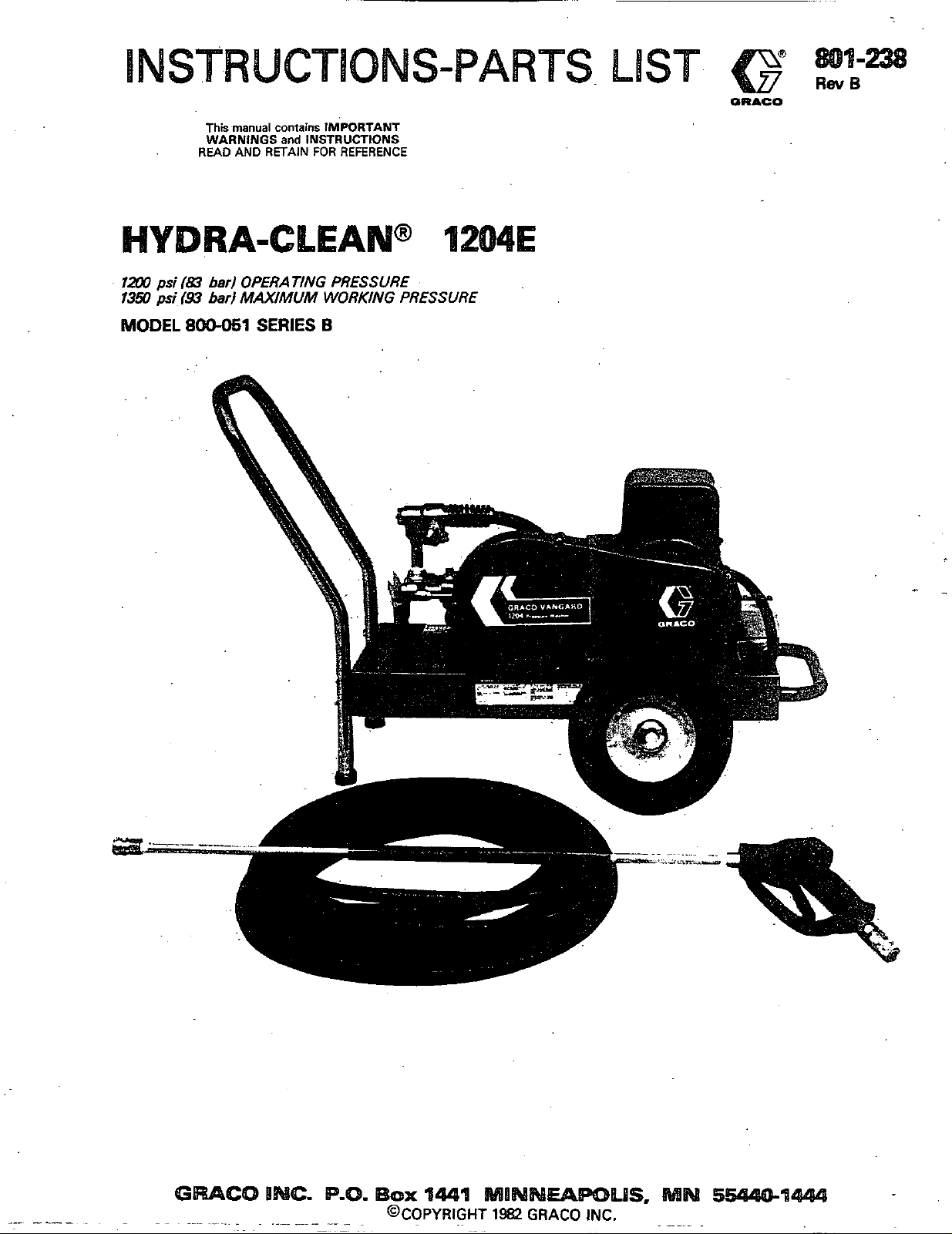
1200
1350
psi
psi
TK~
WARNINGS
READ
(83
bed
(9.3
bad
manual
contains
AND RETAIN
IM'PORTANT
and
INSTRUCTIONS
FOR
REFERENCE
OPERATING PRESSURE
MAXIMUM WORKING PRESSURE
MODEL
8OO-051
SERIES
B
Page 2
HIGH
PRESSURE SPRAY
FOR
PROFESSIONAL
CAN
CAUSE
USE
SERIOUS
ONLY.
INJURY.
OBSERVE
Read and understand all instruction manuals before operating equipment.
IN
JECTlON
fluids under high pressure from spray or leaks can
penetrate
including the need for amputation.
NNER
body.
NNER
NNER
body.
ALWAYS
MEDICAL TREATMENT&~;T:",'?
If
any fluid appears to penetrate your skin, get
Tell the doctor exactlv what fluld
treatment instructions have your doctor
AVOID COMPONENT
Even after you shut
pressure in the pump, hose and gun until
by triggering the gun.
or servicing the unit, ahys shut
the gun to release pressure.
Be sure that
ponents will withstand the pressure developed.
.exceed the pressure rating of any component in system.
NNER
safety, as well as the function of the equipment,
stake.
Before each
ed conditions caused by traffic, sharp corners, pinching
or kinking. Tighten
each
the
skin and cause extremely serious injury,
point the spray gun
at
anyone or any part of the
put hand or fingers over the spray tip.
try
to
stop or deflect leaks with your hand or
have the tip guard in place when spraying.
''<?.X
EMERGENCY
BO
NOT TREAT AS A S!MPLE CUT.
MEDICAL
CARE
was
AT ONCE.
miected. For
Cali
the
NATIONAL POISON CENTER NETWORK
(412)681-6669
RUPTURE"~~,-:r_',":;i.'.
off
the electric motor, there is high
So
before removing the spray tip
off
all
accessory items and system com-
you
relieve
the unit and trigger
NNER
alter or modify equipment-your personal
use,
check hose for weak, worn
all
fluid connections securely before
use.
Replace any damaged hose.
or
damag-
is
at
ALL WARNINGS.
FIRE
Do
not spray flammable liquids.
where combustible fumes or dust may be present.
GENERAL
NNER
run the unit with the belt guard removed. Keep
clear of moving parts when
Observe detergent manufacturer's safety precautions.
Avoid getting detergent or other liquids in your eyes.
Follow the directions on the container regarding contact
with eyes, nose, and skin, breathing fumes, etc. Always
wear full goggles to protect your eyes from the spray as
well
as
any debris dislodged by the spray. If necessary,
wear gloves or other protective clothing. If antidotes or
treatment are recommended, be prepared
DON'T
spray toxic chemicals such
weed killer.
This unit has
from electric shock.
perly grounded outlet that will accept the 3-prong plug.
Do
not remove
The green
unit chassis and motor frame and the other
it
are connected to the motor switch for grounding
continuity.
The electric motor has an overload protection device
which automatically shuts
So,
before examining or working on a motor which has
stopped, shut
the electrical plug. This will avoid the hazard of the
motor starting unexpectedly.
ALWAYS CHECK to be sure the switch
the hoses and electric cord are clear
before plugging in the power cord.
~. ~. . .
:..
.~
,
' '
,..
,
.
.",.
.. .
,
. . .
.
the
;~..._il_x_~**"~.
.
,,,:
,
>,
...
i
~~.<,.,
i.-:
*.'.
Do
not operate the unit
-
,
.
.,
..
,,..,I
,
,,
..
.:,
:k;k'
unit is running.
to
as
insecticide or
a
3-prong grounding plug to protect you
Be
sure to plug the unit into a pro-
the
third
prong.
wire
of the electric cord
off
off
the unit, relieve pressure and pull out
is
connected to the
the motor if
is
OFF
of
moving parts
it
.,-.'i
,
,*.,.
.,.._
,,..
,,,*+
_c.
,
. .
1.
~~ . .
>
,,.!$.,,>~.
..
:.
.:
use them.
two
wires
overheats.
and that
,
Do
not
use
chemicals or agents which are not compati-
ble with Buna-N and PVC or neoprene cover of hose.
Do
not leave a pressurized unit unattended. Shut
off
the
unit and relieve pressure before leaving.
IMPORTANT
United States Government safety standards have been adopted under the Occupational Safety and Health
standards
consulted in connection with your
2,
-
801-238
particularly the General Standards, Part
use
of airless spray equipment.
1910,
and the Construction Standards, Part 1926 - should be
Act.
These
."
Page 3
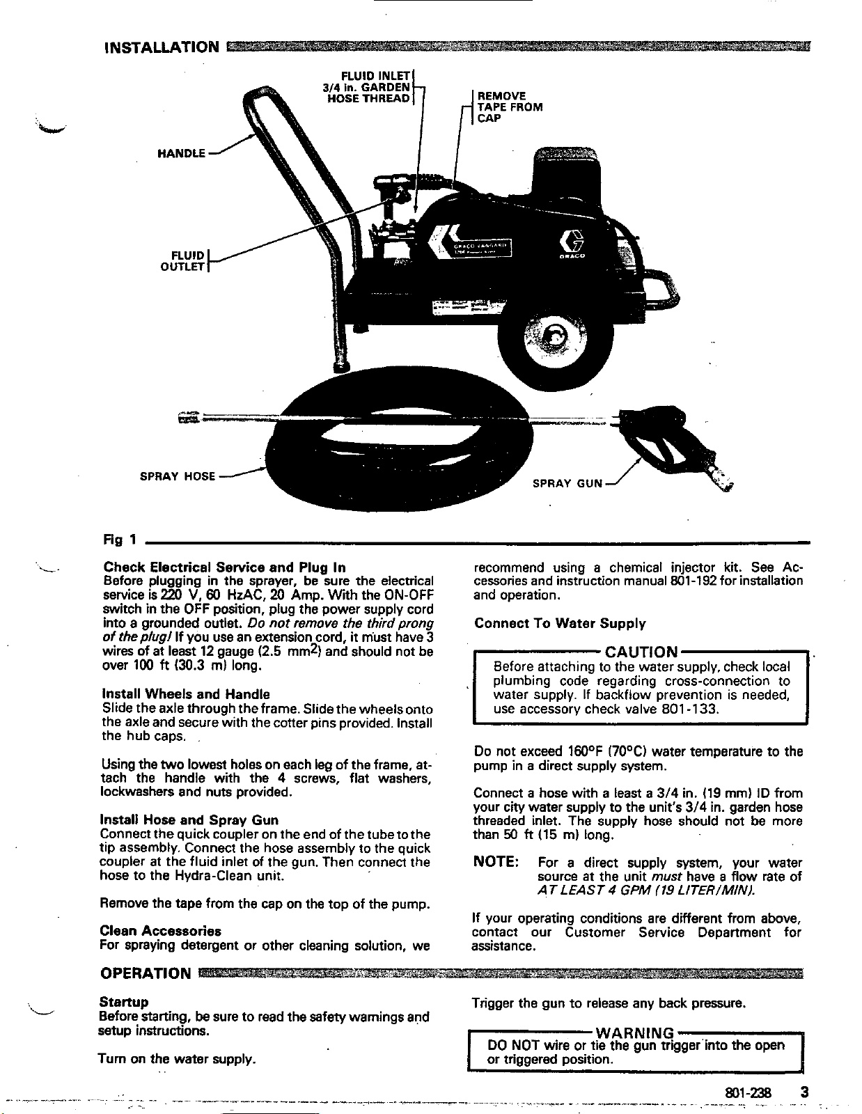
IN
s1
Check Electrical Service and
Before plugging in the sprayer, be sure the electrical
service is
switch in the OFF position, plug the power supply cord
into a grounded outlet.
of
wires of
over 100
Install Wheels and Handle
Slide the axle through the frame. Slide the wheels onto
the axle and secure kith the cotter pins provided. Install
the hub caps.
Using the
tach the handle with the
lockwashers and nuts provided.
Install Hose and Spray Gun
Connect the quick coupler on the end of the tube tothe
tip assembly. Connect the hose assembly to the quick
coupler at the fluid inlet of the gun. Then connect the
hose to the Hydra-Clean unit.
Remove
Clean Accessories
For spraying detergent or other cleaning solution, we
220
V,
60
HzAC,
Do
the
plug1
If you
use
an extension cord,
at
least 12 gauge
ft
(30.3
m)
long.
two
lowest
the tape from the cap on the top of the pump.
holes on each leg of the frame,
Plug
In
20
Amp. With the ON-OFF
not remove the
it
mist have 3
(2.5
mm2)
and should not be
4
screws, flat washers,
third
prong
at-
recommend using
cessories and instruction manual 801-192 for installation
and operation.
Connect
l"-AUT'oNl~
Do not exceed 160OF
pump in
Connect
your city water supply to the unit's
threaded inlet. The supply hose should not
than
NOTE:
If your operating conditions are different from above,
contact our Customer Service Department for
assistance.
To
Before attaching to the water supply, check local
plumbing code regarding cross-connection to
water supply. If backflow prevention
use accessory check valve 801 -133.
a
direct supply system.
a
hose with a least
50
ft
(15
For a direct supply system, your water
source
AT LEAST
a
chemical injector kit. See Ac-
Water Supply
(7OoC)
m)
long.
at
the unit
4
GPM
is
needed,
water temperature to the
a
3/4
in. (19
must
(19
LITER/MIN).
mm)
3/4
in. garden hose
have
a
flow
ID from
be more
rate of
OPERATION
Startup
Before starting,
setup instructions.
Turn
on the water supply. or triggered position.
..
be
sure to read the safety warnings and
Trigger the gun to release any back pressure.
WARNING
DO
NOT
wire
or tie the gun trlgger'into the open
Page 4
CAUTION
unit
Never run the cleaning
the pump will result. Always be sure the water
supply is completely turned on before operating.
Inspect all connections for any leaks. Tighten if
necessary.
Cleaning
For cleaning
jector Kit manual
For cleaning
need to hold the spray nozzle from the surface on a
scrap piece of similar material. For soft surfaces such as
wood, hold the nozzle about
face and gradually bring
high
pressure spray is damaging the surface. Always
hold the nozzle
off
the
the
unit
with
harsh chemicals,
801-192.
with
clear water, test the distance
at
an angle to the surface and "chisel"
dirt.
When you have finished cleaning, shut
and trigger the spray gun to relieve pressure.
dry. Costly damage to
see
the Chemical
3
ft
(1
mm) from the sur-
it
closer, checking to
you
see
In-
will
if the
off
WARNING
Follow these precautions when removing and
stalling nozzles:
1.
Shut
off
to relieve pressure. Engage the trigger safety.
the cleaning unit and trigger the
in-
gun
B
Check the filter screen
often as necessary, at least
unit with the inlet and filter screen removed.
DO
NOT
try
engine speed. Changing these settings may cause
cessive pressure, intermittent unloader operation,
wasted fuel and increased wear on parts and
the warranty.
THE
PUMP
drained of water before exposure to freezing
temperatures.
subjected to freezing temperatures. If water does freeze
in
the unit, thaw before trying to start.
freeze solution may be pumped prior to cold weather
storage.
Use
only spray tips that are matched to the unit to avoid
excessive cycling and wear of the unloader valve.
ACCESSORIES.
pour hot water on a frozen pump.
temperature change may crack .the ceramic
plungers.
I
Do
not pump caustic materials.
to adjust the unloader valve or change the
MUST NOT BE RUN
Use
in
the water inlet connection as
daily.
Do
not operate the
DRY
and store the unit where
ex-
will
void
and must be
it
will not be
A
50%
anti-
See
A
sudden
I
2.
Keep the nozzle and the tube pointed away
from you and everyone
3.
Do
not put your hand over the tip to push the
nozzle into place. Grasp
keep your fingers away from the
4.
Do
not let anyone
while you are changing nozzles.
5.
Be
sure the slip ring is pushed forward to lock
the nozzle in place before triggering the spray
gun.
else.
it
from the side and
tip.
else
touch the spray valve
1
Shutdown
When the unit is not
When shuning down for the day or weekend, shut
the unit, shut
gun
to relieve pressure. Wipe
rag.
and Care of
off
the water supply valve, and trigger the
in
Unit
use,
turn
off
off
the water supply.
the
unit
with a damp
off
Before extended storage, flush the pump with light oil.
Avoid dragging hose over an abrasive surface such as
cement. This causes~excessive wear and shorter hose
life.
Clean the intake line strainer daily.
Lubrication and Care
Fill the pump crankcase to the dot on the oil gauge window with
or equivalent
and
50
hours of operation'and then every 3 months or at
hour intervals.
NEVER
Altering or adjusting unloader
25
oz
(0.75
liters) of crankcase oil
SAE
40
weight hydraulic oil with antiwear
rust
inhibitor additives. Change the oil after the first
alter adjustment or modify the unloader
wi//
erformance of
unit.
not
(801-144)
500
increase'
4
801-238
"
""
""
-- - ---
-~-
Page 5

DISCHARGE VALVES & VALVE SEATS
Disassembly
1.
Loosen the
2.
Then remove the
3.
Grasp the discharge manifold
underside and tap
4.
Valve assemblies will remain with the manifold. Invert manifold and discharge valve assemblies should
fall out.
5.
Inspect discharge valves for wear of ridges. (Spherical valves must be replaced when worn.)
Reassembly
1.
Place retainer
2.
Next insert spring into center of retainer
3.
Place valve over spring
4.
Next insert the valve seat
5.
Position manifold back onto pump.
2
(M8)
locking nuts about one turn.
2
(M8)
with
in
manifold chamber.
with
flange nuts.
with
a
soft
3 fingers on the
mallet to remove.
spherical side down.
NOTE: Exercise caution when inserting cylinders
6.
Replace flange nuts on studs and hand tighten both
sides. Then torque each side to
7.
Hand tighten locking nut.
-
When restarting the pump, checkto see that there
is no cylinder motion as this
failure of the cylinder O-rings. Center cylinder
motion can beeliminated byswitchingwith oneof
the end cylinders.
PUMPING SECTION
Disassembly
1.
Remove discharge manifold as described above.
2.
Slip cylinders out of inlet manifold.
NOTE: Identify cylinders
3.
Remove cotter pin, nut, and washer.
into manifold to avoid damaging cylinder
O-rings.
125
in-lb.
CAUTION
will
cause premature
1
BE2
so
they
will
be replaced
in
their original position. (Front to back.)
4.
Next
remove piston retainer, spacer, and piston
assembly.
5.
Remove inlet valve
Page 6

Reassembly
1.
Examine inlet valve surface and reverse if damaged.
(Both sides are lap surfaces.)
2.
Examine piston assembly for clean inlet surface.
damaged, replace and lubricate.
NOTE: CUP INSTALLATION
3.
Next replace piston spacer and retainer.
4.
Slip washer onto rod, screw on
in-lb.
5.
Examine cylinder wallsfor scoring oretching.These
conditions
assemblies. Replace if worn or damaged.
6.
Lubricate cylinder and replace O-rings and backup
rings (if defective).
Wipe
cup inserter lightly
ring onto piston. Force cup over inserter and
square
tion causes premature failure.
ALWAYS USE NEW COTTER PIN.
with
all surfaces. Faulty cup installa-
will
cause premature wear of piston
with
oil. Slip backup
nut
and torque to
If
60
SEALS AND
Disassembly
1.
Remove discharge manifold and piston assemblies
as described.
2.
Remove both
3.
With soft mallet, tap inlet manifold loosefromcrankcase.
4.
Place inlet manifold on pair of clearance blocks
crankcase side down, and drive out seals.
5.
Invert inlet manifold
6.
Lubricate circumference of new Prrrrrm-A-Lube
seals, position
DOWN and drive into place.
7.
Examine sleeves for scoring or other damage before'
removing.
8.
If worn, grasp sleeve
SLEEVES
(ME)
locking nuts from studs
with
CRANKCASE
in
manifold with GARTER
with
pliers and pull off.
SIDE
UP.
SPRING
with
7.
Position cylinders
chambers and carefully slip over rod ends onto the
pump.
8.
Replace flange nuts on studs and hand tighten both
sides. Then torque each side to
9.
Hand tighten locking nuts.
PUMPING SECTION CUTAWAY
in
their original order into manifold
125
in-lb.
NOTE: This procedure will marthesleeveso use
only if sleeve is
9.
Remove O-ring and backup rings from piston rod.
Reassembly
1.
Place barrier slinger on rod
2.
Lubricate new o:rings and backup rings. Install first
O-ring
in
backup ring against the shoulder
O-ring, then the second O-ring. Be careful to avoid
damaging the O-rings when slipping them over the
piston rod threaded ends.
3.
Immerse sleeve
rod. (Machined counter bore end first.)
4.
Replace seal retainers.
5.
Be careful when replacing inlet manifold,
let seals are not damaged by the threaded rod ends.
6.
Replace locking nuts on studs.
7.
Reassemble piston assemblies and discharge mani-
fold as described.
Consult factory for your local distributor for crank-
case servicing.
the O-ring groove on the piston rod. Position
in
oil, carefully twist and push onto
to
be replaced.
in
front of the first
so
the
in-
PROBLEM
Low
pressure
DIAGNOSIS AND MAINTENANCE
PROBABLE CAUSE
Worn nozzle.
Belt slippage.
Inlet suction strainer clogged.
in
Worn plunger cups. Abrasives
fluid or severe cavitation. Inadequate
water supply.
pumped
SOLUTION
Replace nozzle, of proper size.
Tighten or replace; use correct belt.
Clean. Check more frequently.
Install proper filter.
..
Page 7

SOLUTION
Low pressure
Pump
rough,
low
Cylinder O-rings blown
next to discharge
manifold
Leakage
0-Rings
discharge manifold and
black, powdery
substance
of
Water leakage from Worn inlet manifold seals.
under the inlet
manifold.
runs
pressure very
the 0-Rings.
(Cont.)
extremely
at the cylinder
at the
in
the 'area
Fouled or dirty inlet or discharge valves.
Worn inlet or discharge valves. Leaky
discharge hose.
Inlet restriction andlor air leaks. Damaged cup or stuck inlet or discharge valve.
Worn inlet manifold seals.
Pressures
Warped manifold.
Loose cylinders. Cylinder motion caused
by improper shimming of the discharge
manifold.
Leaking sleeve 0-Ring.
in
excess of rated PSI.
Clean inlet and discharge valve
assemblies.
Replace worn valves, valve seats and/c
discharge hose.
Replace worn cup or cups, clean out
foreign material, replace worn valves.
Replace worn seals.
Check for plugged nozzle. closed valve!
or improperly adjusted by-pass valve.
Replace manifold.
~~
Exchange middle andoutboardcylinder,
Install new seals. If piston rod sleeves
are scored, replace sleeves and sleeve
0-Ring.
0-Rings,
Oil leak between Worn crankcase piston rod seals.
crankcase and
ing
section
Oil leaking
of
crankcase
Excessive
end of the
pulley
Water
Oil leakage from under May
side
Dil leaking at'tha rear Damaged or improperly installed oil gauge
portion
xankcase
3il leakage from drain
,lug
in
of
crankcase wick lubricators.
of
-
pump-
in
the area
in
play
crankcase tension to drive
crankcase May be caused by humid air condensing
the
the
Worn crankcase seal or improperly install.
oil
seal retainer packing.
ed
Bad bearing.
Worn main
into water inside the crankcase.
Leakage of manifold inlet seals and/or
piston rod sleeve 0-Ring.
be
Worn crankcase piston rod seals.
or crankcase rear cover 0-Ring, and drain
I
~lua
0-Ring.
Loose
I
0-Ring.
ball
bearing from excessive
belt.
:
caused by excessive oiling of the
drain plug or worn drain plug
.
Replace crankcase piston rod seals
Remove oil seal retainer and replace
damaged gasket and/or seals.
Replace bearing.
Replace ball bearing. Properly tension
belt. Check shaft shims.
Change'oil every month or
Replace seals, sleeve and 0-Rings.
Wipe free of oil.
for
a
short period. If leakage continues,
replace the crankcase piston rod seals.
Replace oil gauge or cover 0-Ring, and
drain
plug 0-R,ing.
righten drain plug or replace 0-Ring.
Do
200
hours.
not oil lubricators
.oud
knocking noise
lump
hquent
ailure
nanifold seals
lhort
of
cup
in
Pulley
loose
on crankshaft.
Broken or worn bearing.
or
premature Scored rods or sleeves.
the inlet
I
Overpressure to inlet manifold.
life
Damaged or worn chrome plating of the
cvlinders.
I
:heck key and tighten set screw.
3eplace bearings.
3eplace rods and sleeves.
3educe inlet pressure per instructions.
3eplace the cylinders.
Page 8

DIAGNOSIS AND MAINTENANCE CONT
I
PROBLEM
Short
cup life
Strong surging a the
inlet and
on
the discharge side.
low
(Cont.)
pressure
PROBABLE CAUSE
Abrasive material
pumped.
Excessive pressure and/or temperature of
fluid being pumped.
Improper installation of cups.
Overpressure of pumps.
Running pump dry.
Front edge of piston sharp.
Chrome plating of cylinders damaged
causing excessive wear of cups. May be
caused
Foreign particles
valve or worn inlet and/or discharge
valves.
bv
Dumping acid solution.
in
the fluid being
in
the inlet or discharge
SOLUTION
Install proper filtration of pump inlet
plumbing.
Check pressures and fluid inlet
temperature; be sure they are within
specified range.
Properly install
groove on the
stalled, the cup
piston. Piston will run eccentric;
premature failure will result.
Reduce pressure.
Do
not run pump without water.
Replace with new piston.
Install new cups and cylinders. Pump
only fluid compatible with chrome.
:heck for smooth lap surfaces on inlet
and discharge valve seats. Discharge
valve seats and inlet valve seats.
Discharge valve seats and inlet valve
seats may be lapped on a very fine oil
stone; damaged cups and discharge
valves cannot be lapped but must be
.eplaced.
lip of new cup into
piston. If not properly in.
will
be extruded past th
Water leaking
valve stem
Short piston seal life.
from
I
I
Electric motor
I
run'
Electric motor stops
while spraying
won't
Norn piston seal.
-oose cleanout port
-eak
in
discharge hose.
.oose
stuffing box.
scored piston sleeve.
in
4brasives
'ower cord unplugged, or building circuit
use
blown.
lverload switch has opened.
'ower cord unplugged, or building circuit
use
blown.
lverload breaker has opened.
Ixtension cord.
-ip plugged.
water.
nut.
~ ~~~
3eplace seal assembly.
righten nut.
3eplace hose.
righten.
3eplace piston sleeve.
:lush
with
clean water.
:heck, replace.
Jnplug power cord', decrease pressure.
:heck, replace.
Jnplug power cord', relieve~pressure-
IllOW
to cool.
Ion't
use
more
than
100
h
of
12
ga ex-
ension cord.
lemove and clean.
Electric motor
Electric
when starting; blows
fuses
'This
30
to
motor
unit
60
runs,
labors
has an overload breaker
minutes. Also, try to correct the cause of overheating. Always
)isplacement pump frozen or gear train
lamage.
:aDacitor failure.
built
into the switch assembly. If
it
.haw
leplace capacitor.
opens, unplug power cord and let sprayer cool for
use
the lowest pressure setting needed.
Page 9

i
trv
PARTS
Gun and
14
5
A
DRAWING
Hose
Assembly
3
L
L
QTV
1
for
Repair Kit
Includes items
801083
A,
B,
C.
D,
E
and
F
SERVICE
1.
Remove the 8 screws from the body halves
(41.
See
the Parts Drawing. Separate the body
halves.
2.
Remove
the valve body
3.
Remove the snap ring
seat
4.
Remove
actuator rod
5.
After installing the
ball
between the ball and seat.
6.
Reassemble
new parts from the repair
(C)
and o-ring
lightly
the
plug
(14),
spring
15)
and
(GI.
(6).
Then remove the valve
(D).
the
sleeve
(F).
with
in
nut
(11)
and o-ring
new
seat
IC)
a
hammer
and ball
to
assure a proper seating
reverse order, using the remaining
kit.
ball
(E)
(AI,
(3)
and
(A)
from
with the
tap the
REF
.
NO. NO.
1
2
3
4 801-245
5
6
7
8
9 801-261
10
11
12
13 801-263
14
15 801-264
16 801-265
17
..
18 801-029
19 "801-009
20
21 801473
22
23
24 801474
25
26
27
28
Order
which
PART DESCRIPTION
801-007
800-017
801-244
801-249
801-254
801-256
801-262
~~ ~~
801-247
801.253
. 801-246
801-250
ml-1.34
".
."
'801-090
*801-374
'801-373
801-076
801477
801-103
'801491
parts
by
are
name
ordering.
you
SPRAY HOSE,
I15
m)
Ig
SPRAY GUN, lreplaceable
include items
.
HANDLE,
. HANDLE,
. SPRING
3/8"
3-16)
left
right
ID,
50
fl.
parts
. LEVER
. NEEDLE
. HEX PLUG
.
DISCHARGE FITTING
' '
. VALVE BODY
. GUIDE SLEEVE
. TUBE
. INLET FITTING
.
CAP
. SCREW
. SCREW
32"
TUBE,
GRIP
COUPLER, female
COUPLER,
HOUSING,
TIP, blasting;
TIP, cleaning;
GUARD, tip
PLATE, warning
RIVET
NIPPLE,
hex;
COUPLER, male auick disconnect
and
series
quick
male
quick disconnect
nozzle
0'
15"
1/4
x
3/8"
lener
disconnect
npt; brass
of the assembly
Wecommended "tool
**Replacement 0-Ring for Coupler
".
..~
-
.."
~~
"
.
".
,
.,.
....
~
,,
.._,_
"
_.
.
".
~
".
."
-
-. ~ .-
box"
.
. .
spare
.
pam.
Pen
.
"
..
No.
__
801-202.
801-238
.,
I
9
-.
. ..
-
.
. .
Page 10

T91
Ts
11
T4
T8-
MOTOR
POWER
1213
-
-
-
COR0
-
GRN
STARTER SWITCH
BLK
b
OFF
ON
SWITCH
BLK
WHT
BLK
Page 11

PARTS DRAWING
21
PARTS
REF PART DESCRIPTION
NO. NO.
LIST
an
REF
NO. NO.
PART
Piston
(Includes Ref. No's. 7-12, 18)
Valve
(Includes Ref. No's.
Cup
(Includes Ref. No's.
DESCRIPTION
kit
kit
kit
801-321
801 -322
801 -1
96
13-1
8,
12.
8)
18)
20
21
P
23
24
25
26
27
28
29
30
31
.~
32
33
34
35
36
37
38
..
42
43
44
45
46
47
50
51
52
53
1
800-016 MOTOR, 3
2
8ooM)9
801-270
3
4
801-198
5
801428
6
801-356 ..STUD
801-273 . HOSE, cpld 112 nptlmbe), 19 long
801-181
801-1 11 . NUT, brass, garden hose adapter
801-112
801-106
801-105
801-178
801-269
801-090
801-108
801-182
801-203
801-045
801
801-047
801-048 .. BALL
801-049
801-050
800013
801-143
801453
801-060
801-061
801-062
801-063 ..PLUG
801-068
801-069
801070
mo1-071
"
. - . .
801-176 BASE, belt guard
801-375 BELT, drive
801-300 PULLEY, pump
801-299 PULLEY, motor
PUMP ASSEMBLY. includes items
3-49
. PUMP, Ref No. 4-6 are replaceable
parts. Ref No. 7-19 are sold in kits
""I"
-...,
..
CAP
.. O-RING
. PROTECTOR,
. SCREEN, inlet, 112"
. TEE, brass, 112 npt
.
NIPPLE, straight, brass, 1/2 npt
3-1
.
ELBOW, street,
. PLUG, hex, brass, 3/8 npt
. COUPLER, male quick disconnect
. BUSHING. hex reducina brass. 114
x
112 npt
. NIPPLE, straight, steel, 112 npt
2.112"
-
.
ADAPTER,
. UNLOADER, includes items
.. CAGE, valve
.. O-RING
-046
.. SPRING
..
SEAT
.. O-RING
._ UNLOADER
..
TAG
.. O-RING
.. HOUSING
.. CYLINDER
.. GASKET
..
HOUSING, valve
..
SPRING
__
VALVE
SFAT
.
.
-
_.
12"
.
,
hp
112"
shaft
9O0,
garden hose
1/2 npt
I
x
x
33-49
54
55
56
57
58
59
60
61
62
63
64
65
66
67
1
2
2
1
1
1
1
1
1
2
68
69
70
n
73
74
..
75
76
77
2
1
1
1
1
1
1
2
1
1
1
Order
which
800"
800414
801012
801413
€fO-O15
".
801-231
801-240
801-293
801-241
801-214
801-291
801
801-023
801-024
801025
801
801-363
801-177
801-139
801-170
801-137
801-173
801-087
801415
801-132
801-130 LABEL, warning
801-129 LABEL, warning
801-141 LABEL. warning
801-204 LABEL. identification
801-008 LABEL. identification
801-242 CAP, hub
811-292 SCREW, self-tpg, flat hd, 6-32
801-235 WASHER.
61-% PIN,-cotter
801-225 STRAIN RELIEF
801-296 CONNECTOR, flexible conduit
801-294 CORD, power
801-295 SWITCH, starter
801-290 BOLT. carriage, 5/16-18
801-376
parts by name and series letter of the assembly for
'
you are ordering.
SPRAY GUN ASSEMBLY, see parts
on page
CHASSIS
GROMMET
HANDLE
FOOT
. ".
LABEL. caution
AXLE
TENSIONER, belt
WHEEL
BOLT, hex
BOLT, carriage, 5/16-18
ai2
SCREW, hex hd, 5/16-18
WASHER, flat, 1/4"
NUT, hex, 5/16
LOCKWASHER, 5/16
-298
BOLT. hex hd. 5/16-18
WASHER, lock, 3/8
COVER, belt guard
LOCKWASHER,
SCREW, hex hd mach, M6 x 25
KEY, pulley
KEY, pulley
SCREW, mach. cros recessed,
1
14-20
WASHER, flat, 5/16
RIVET
HUB.
9
x
1-3/4"
pulley
hd.
3/8-16 x 1-3/4"
1/4"
flat
~~
x
x
x
x
3"
3.5
1-3/4
2-1/2"
x
mm
112
A
12
6
8
5
4
2
1
2
2
2
-
2
1
1
1
1
1
1
A
1
Page 12

ACCESSORIES (Must
be
purchased
separately)
CHECK VALVE
Prevents
supply.
back
Install
801-133
up
of
upstream
contaminated
from
pump.
water
into
fresh
TECHNICAL DATA
ELECTRIC MOTOR
WATER PUMP: 1200 PSI
WElTED PARTS :Stainless
WEIGHT:
OVERALL DIMENSION
CHEMICAL INJECTOR KIT
For
injecting
from
pump.
:
max.
(15 litarlmin)
Phenolic Plastic, Nitrile Rubber
Steel,
165
Ib
:
Length: 30"
Width:
28"
Height:
25.5
pressure:
4
GPM
Aluminum.
1810
(710
mml
(650
harsh
mm)
mm)
cleaning
800-102
chemicals
downstream
MAX.
WATER
INLET HOSE CONNECTION
TEMPERATURE:
1W
(70°C)
:3/4"
garden hose
(f)
LIMITED WARRANTY
We wamnty each new machine sold by us to
Wring
defects in normal
mencing with deliwry of the machine to the original owner.
Our
obligation under this warranty
to
the
replacement or repair
or
a
Minmta
aa
iMpection
doas not
(including
service
shall disclose to have been defective. This warranty
nwlv
to defects caused
i&re
service
for a period
is
facili ddgnated
to
provide reasonable and
at
bv
expressly limited
while in the won of the consumer.
TO
NOT APPLY
WE SHALL NOT BE LIABLE
ANY THING, including but not limited
tranbpomtion charges in connection with the replacement or repair of
defective
We
make
THE WATER NOZZLE
pam.
no warranty
FOR
CONSEOUENTIAL DAMAGES
with
respect to trade accessories.
subject m the warranties of their manufacturers.
be
free from manuiac-
of
one
(0
war
at
Vangard Mfg., Minneapolis,
by
us, of such
damaoe
to,
or
nacessarv
THIS
WARRANTY DOES
OR
V-BELTS.
consequential labor costs
our option,
pan
unreasonable
maintenance)
or
They
com-
pam
use
OF
or
nre
Sub.ldt.y
FrntoryB-
and
GRACO
AflUlata
INC.
-Atlama.
Dallas.
Detroit.
Loa
Angel-.
Weat
Caldwdi
IN.J.1
Campnk.:Canada: England: Swttzarland France: Germany: Hone Kong: Japan
P.
0.
Box
1441
PRINTED
MINNEAPOLIS,
IN
U.SA
801
-238
5/82
MN
5"1444
"
lblmxB
 Loading...