

Graco Inc Hydra-Clean 800-907, Hydra-Clean 1040, Hydra-Clean 800-906, Hydra-Clean 800-908, Hydra-Clean 308-534 User Manual
...Page 1
INSTRUCTIONS-PAR
This
manual contains
WARNINGS
AND
RET
and
AIN FOR REFERENCE
IMPORTANT
INSTRUCTIONS
READ
TS LIST
308–534
Rev
A
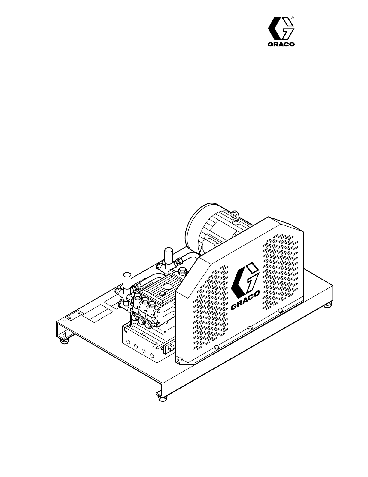
HYDRA-CLEAN
Pressure W
Model
800–906, Series A 230/460 V
Model 800–908, Series A 230/460 V
700 psi (48 bar) OPERA
1
100 psi (75
Model 800–907, Series A 230/460 V
Model 800–909, Series A 230/460 V
1000 psi (69 bar) OPERA
1300 psi (91
bar) MAXIMUM WORKING PRESSURE
bar) MAXIMUM WORKING PRESSURE
ashers
olt, 3 Phase, 35 GPM
olt, 3 Phase, 40 GPM
TING PRESSURE
olt, 3 Phase, 35 GPM
olt, 3 Phase, 40 GPM
TING PRESSURE
735, 740, 1035, 1040
W
ater supply tank, gun & wand assembly
GRACO INC. P
.O. Box 1441 MINNEAPOLIS, MN 55440–1441
COPYRIGHT
, hose assembly and motor starter are not included.
1991, GRACO INC.
Page 2

HIGH PRESSURE SPRAY CAN CAUSE SERIOUS INJURY.
FOR PROFESSIONAL USE ONLY. OBSERVE ALL WARNINGS.
Read and understand all instruction manuals before operating equipment.
FLUID INJECTION HAZARD
WARNING
General Safety
This
pressure washer generates very high fluid pressure.
Spray from the gun, leaks or ruptured components can
inject fluid through your skin and into your body and
extremely serious
cause
for amputation. Also, fluid injected or splashed into the
or on the skin can cause serious damage.
eyes
NEVER
part of the body .
spray
ALWAYS
cleaning
NEVER
body.
Be
before
point the spray gun or wand at anyone or at any
tip.
follow the
or servicing any part of the sprayer
try to stop or deflect leaks with your hand or
sure equipment safety devices are operating properly
each use.
bodily injury including the need
NEVER
put hand or fingers over the
Pressure
Relief Procedure
,
before
.
Medical Treatment
If any fluid appears to penetrate your skin, get
EMERGENCY MEDICAL TREATMENT AT ONCE. DO
TREA
NOT
what
NOTE TO PHYSICIAN:
traumatic
surgically as soon as possible.
treatment
with
bloodstream.
reconstructive
T AS A SIMPLE CUT. T
fluid was injected.
injury
.
It is important to treat the injury
to research toxicity
some exotic coatings injected
Consultation with a plastic surgeon
hand surgeon may be advisable.
ell
the doctor exactly
Injection in the skin is a
Do not delay
. T
oxicity is a concern
directly into the
or
Pressure Relief Procedure
To
reduce the
injection
follow this procedure whenever you stop spraying for
more than 10 minutes, when shutting down, and before
checking
1.
Engage the trigger safety latch.
2. T
urn the sprayer of
Disconnect the electrical supply
3.
4.
Shut of
5. Disengage
to relieve pressure, and then engage the trigger
safety
6. Before long–term (overnight) storage, disconnect
the
risk of serious bodily injury
and splashing in the eyes
or repairing any part of the system.
f.
f the water supply
the trigger safety latch and trigger the gun
latch again.
water supply and disconnect the electricity
.
, including fluid
or on the skin, always
.
.
Spray Gun Safety Devices
Be sure all gun safety devices are operating properly
each use. Do not remove or modify any part of
before
gun; this can cause a malfunction and result in serious
injury
bodily
SAFETY LA TCH: Whenever you stop spraying for a
moment,
or
“safe” position, making the gun inoperative. Failure to
properly set the safety latch can result in accidental
triggering
SPRAY TIP SAFETY: Use extreme caution when
cleaning
spraying, engage the gun safety latch immediately.
ALWAYS
remove the spray tip to clean it.
then
.
always set the gun safety latch in the engaged
of the gun.
or changing spray
follow the Pressure Relief Procedure and
tips. If a spray tip clogs while
the
Page 3

GROUNDING INSTRUCTIONS
This product must be grounded. If it should malfunction
or break down, grounding provides a path of least
resistance
shock.
equipment–grounding conductor and a grounding plug.
The
is properly installed and grounded in accordance with
local
for electric current to reduce the risk of
This equipment is equipped with a cord having an
plug must
codes and ordinances.
be plugged into an appropriate outlet that
electric
all
Improper connection of the equipment–
grounding conductor can result in the risk of
electrocution.
service person if you are in doubt as to whether
outlet is properly grounded.
the
GROUND FAULT CIRCUIT INTERRUPTER PROTECTION
To comply with the National Electrical Code (NFP A 70)
and to provide additional protection from the risk of
electric
that is protected by a ground–fault circuit–interrupter
(GFCI).
shock, connect this pressure washer to a circuit
EQUIPMENT MISUSE HAZARD
General Safety
Any
misuse of the pressure washer or accessories, such
as
overpressurizing, modifying parts, using incompatible
chemicals and fluids, or using worn or damaged parts,
can cause them to rupture and result in fluid injection,
splashing in the eyes or on the skin, or other serious
injury
bodily
, fire, explosion or property damage.
System
This sprayer can develop high operating pressure. Be
sure
to withstand the maximum working pressure of this
sprayer.
pressure of any component or accessory used in the
system.
Pressure
that all spray
DANGER
Check with a qualified electrician or
equipment and accessories are rated
DO NOT
exceed the maximum working
NEVER
so
CHECK
replace
ALWAYS
clothing.
chemical manufacturer’s literature for
on
alter or modify any part of this equipment;
could cause it to malfunction.
all spray equipment regularly and repair or
worn or damaged parts immediately
wear protective eyewear and appropriate
If using
additional protective equipment, such as a respirator
a chemical injector
, read and follow the
recommendations
.
doing
Chemical Compatibility
BE
SURE
that
all chemicals used in the chemical injector
are compatible with the wetted parts of the hose, gun,
and tip, as given in
wand
cover). Always read the chemical manufacturer ’s
literature before using any chemical in this pressure
.
washer.
the T
echnical Data (inside back
Page 4

HOSE SAFETY
High
pressure fluid in the hoses
the
hose develops a leak, split or rupture due to any kind
of wear , damage or misuse, the high pressure spray
emitted from it can cause a fluid injection injury or other
serious bodily injury or property damage.
can be very dangerous. If
ALL FLUID HOSES MUST HA VE STRAIN RELIEFS
BOTH ENDS.
ON
from kinks or bends at or close to the coupling, which can
result
in hose rupture.
TIGHTEN
High
high
all fluid connections securely before each
pressure fluid can dislodge a loose coupling or
pressure spray to be emitted from the coupling.
The strain reliefs help protect the hose
use.
allow
MOVING PARTS HAZARD
NEVER
entire hose for cuts, leaks, abrasion, bulging cover , or
damage or movement of the hose couplings. If any of
these
NOT
tape
the
HANDLE AND ROUTE HOSES CAREFULL Y.
pull on hoses to move the pressure washer. Do not use
chemicals which are not compatible with the inner tube
and cover of the hose.
temperatures
(–40_ C).
use a damaged hose. Before each use, check
conditions exist, replace the hose immediately
try to recouple high pressure hose or mend it with
or any other device. A repaired hose cannot contain
high pressure fluid.
above 200
DO NOT
_ F
expose Graco hose to
(93
_ C)
or below
Do not
–40
.
DO
_ F
Moving
parts.
operating
NEVER
and interlocks installed and functioning. Follow the
parts can pinch or amputate fingers
KEEP CLEAR
the pressure washer
operate the pressure washer without all guards
of moving parts when starting or
.
or other body
Pressure Relief Procedure before checking or
servicing the pressure washer to prevent discharging
pressure fluid from the gun.
high
TERMS
WARNING
conditions
CAUTION:
could
or DANGER:
that could cause bodily injury
Alerts user to avoid or correct conditions that
cause damage to the equipment.
Alerts user to avoid or correct
.
NOTE:
Identifies helpful procedures and information.
IMPORTANT
United
States Government safety standards have been adopted under
standards—particularly the General Standards, Part 1910, and the Construction Standards, Part 1926—should be
consulted.
the Occupational Safety and Health Act. These
Page 5
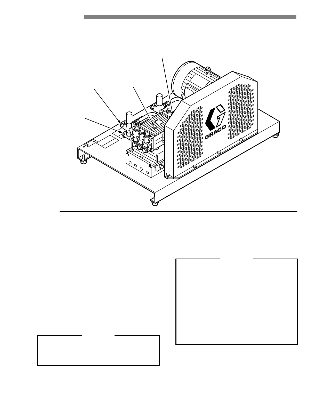
INSTALLATION
HIGH
PRESSURE
HOSE
CONNECTION
2 x 1/2” NPT(f)
WATER
CONNECTION
2 x 1” NPT(f)
PUMP DIP
STICK
PUMP OIL
LEVEL
INDICATOR
WINDOW
-
Figure
1
Check for Shipping Damage
Check
the unit for
shipping. Notify the carrier immediately if there is any
damage.
any damage that may have occurred in
Set Up
Before
connecting the unit, be sure the electrical
matches
cover)
connect the power supply cord to a grounded,
GFCI–protected
If
you are using a
between
Connect
and
the specification in T
and the voltage label
circuit.
downstream chemical injector
the pump unloader and the
the
high pressure hose between the pump outlet
the gun inlet.
echnical
on the unit. With the unit of
Data (inside back
high pressure hose.
service
f,
, install it
CAUTION
Up to 100 ft (30 m) of high pressure hose may
be used.
performance,
if
used.
Longer hoses may af fect sprayer
and chemical injector
performance,
W
ater supply tank, gun & wand assem
, hose assembly and motor starter are
bly
-
not included.
Install the appropriate spray tip on the wand. See
Installing and Changing Spray T ips. If you are using a
sandblaster kit, see its separate manual for installation
instructions.
Connect to Water Supply
CAUTION
Before attaching to the water supply, check your
local plumbing code regarding
to the water supply
backflow preventer P/N 801–133 is available
A
prevent backflow of contaminated water into the
fresh water supply . Install it upstream from the
pump.
Install a regulating water valve, P/N 800–258, if
water pressure is over 60 psi (4.1 bar).
inlet
Do not exceed 160 _ F (70 _ C) inlet water
temperature.
NOTE: The water source for the unit
minimum 100 gallon float valve controlled
water
.
holding tank.
cross–connection
to
must
have a
Page 6

STARTUP
Use this procedure whenever starting the pressure
washer
starting
1.
2. Turn
to help insure that the unit is ready to operate and
is done safely
Check the oil level.
Pump:
Add SAE 20 or 30 weight non–detergent oil as
necessary.
on the water supply
.
.
CAUTION
Never run the unit dry . Costly damage to the
pump will result. Always be sure the water
supply is completely turned on before
operating.
3. Trigger the gun until water sprays from the tip
indicating
4.
Start the unit.
5.
ALWAYS
whenever you stop spraying, even for a moment to
reduce the risk of fluid injection or splashing in the
eyes
accidentally.
that the air is purged from the system.
engage the gun’ s trigger safety latch
or on the skin if the
gun is bumped or triggered
6.
ALWAYS
costly
observe the following CAUTIONS
damage to the pressure washer
to avoid
.
CAUTION
DO NOT
more
recirculating water to overheat and seriously
damage the pump. T urn of f the pressure
washer if it will not be spraying or cleaning at
least every 10 minutes. If heated inlet water is
used,
DO NOT
damage
fully
DO NOT
materials
7. See the chemical injector or sandblaster kit manual
for
are
allow the pressure washer to idle for
than 10 minutes. Doing so may cause the
reduce this time further
run the pump dry , which will quickly
the pump. Be sure the
turned on before starting the pump.
pump caustic materials; such
may corrode the pump components.
detailed cleaning information if these
used.
.
water supply is
accessories
6ą308-534
Page 7

Trigger Safety Latch
WARNING
To reduce the risk of serious bodily injury ,
including
on
latch whenever spraying stops, even for a
moment.
fluid injection, splashing in the eyes or
the skin,
ALWAYS
engage the trigger safety
Installing and Changing Spray Tips
WARNING
To reduce the risk of serious bodily injury ,
including
or onto the skin, use extreme caution when
changing spray tips.
procedure
fluid injection or splashing in the eyes
below
ALWAYS
.
follow the
the engaged position, the
In
prevents the gun from being triggered
accidentally by hand or if it is dropped or
Be
bumped.
when engaging it or it cannot prevent the gun
being triggered. See Figure 2.
from
TRIGGER SAFETY LA
sure the latch is pushed fully down
trigger safety latch
TCH SHOWN ENGAGED
1.
Follow the
2. Point the gun and wand away from yourself and
anyone
3. Without
back
then
4. Be sure the tip is secure before starting to spray
again.
5. Tip
holding holes are provided on the chassis.
Pressure Relief Procedure
else.
holding your hand over the spray tip (A), pull
the quick coupler ring (B), remove the tip and
release the ring. See Figure 3.
.
CAUTION
To avoid blowing the o–ring out of the quick
coupler,
never
securely
due to the high pressure in the system,
operate the pressure washer without a tip
mounted in the quick coupler
.
TRIGGER SAFETY LA
Figure 2
TCH SHOWN DISEN
GAGED
A
B
-
Figure 3
308-534ą7
Page 8

SHUTDOWN, FLUSHING AND STORAGE
WARNING
PRESSURE
To reduce the risk of serious bodily injury ,
including fluid injection and splashing in the
eyes, or on the skin, always follow this
procedure whenever you stop spraying for
more than 10 minutes, when shutting down,
before checking or repairing any part of the
and
system.
1. Engage
2. T
urn the sprayer of
3.
Disconnect the electrical supply
Shut of
4.
5. Disengage the trigger safety latch and
the gun to relieve pressure, and then
trigger
engage
6. Before long–term (overnight) storage,
disconnect the water supply and
disconnect
RELIEF PROCEDURE
the trigger safety latch.
f.
.
f the water supply
the trigger safety latch again.
the electricity
.
.
1. If the pressure washer will be exposed to freezing
temperatures, drain all water out of the pump. If it
must be stored in freezing temperatures, flush the
unit with a 50% anti–freeze solution. Relieve
pressure.
again
Flush the pressure washer before using it
to remove the anti–freeze.
CAUTION
If water does freeze in the pressure washer ,
thaw it in a warm room before trying to start it.
DO
NOT
pour hot water on
may
crack the ceramic plungers!
2. After each use, wipe all surfaces of the pressure
washer
3. Perform the appropriate maintenance. See the
maintenance
with a clean, damp cloth.
chart.
or into the pump; it
MAINTENANCE
Observing regular maintenance intervals helps ensure
that you get maximum performance and life from the
pressure
There
the oil initially, the interval between required changes is
longer.
washer
is a break–in period for the pump. After changing
To reduce the risk of serious bodily injury ,
including
on
the skin or injury from moving parts, always
follow the Pressure Relief Procedure
Warning
.
WARNING
fluid injection, splashing in the eyes or
before proceeding.
Interval
Daily
After first 50
hours of
operation
Each 500 hours
of operation or 6
months
What to do
Clean water inlet screen and
filter
. Check pump oil level. Fill
as necessary
Change pump break–in oil. Use
SAE 20 or 30 non–detergent oil.
Change pump oil. Use SAE 20
or 30 non–detergent oil.
.
Page 9

TROUBLESHOOTING CHART
WARNING
To
reduce the risk of serious bodily injury
injury
from moving parts, always follow the
PROBLEM CAUSE SOLUTION
Low
pressure and/or
pump runs rough
W
ater leakage from
under pump manifold
W
ater in pump
Frequent or
premature failure of
the packings
Strong surging at the
inlet and low pressure
on the discharge side
Unit will not start
W
orn or wrong size tip.
Inlet filter clogged.
W
orn packings, abrasives in water or
natural wear
Inadequate water supply
Belt slippage.
Fouled or dirty inlet or discharge valves.
Even a small particle can cause the valve
to stick.
Restricted inlet.
W
orn inlet or discharge valves.
Leaking high pressure hose.
orn packings.
Humid air condensing inside crankcase.
W
orn packings.
Oil seals leaking.
Scored, damaged or worn plungers.
Abrasive material in the fluid being pumped.
Inlet water temperature too high.
Overpressurizing pump.
Excessive pressure due to partially plugged
or damaged tip.
Pump running too long without spraying.
Running pump dry
Foreign particles in the inlet or discharge
valve or worn inlet and/or discharge
valves.
Unit not plugged in.
Electrical service of
Thermal overload has tripped.
.
.
f/GFCI activated.
, including fluid injection, splashing in the eyes or on the skin, or
Pressure Relief Procedure W
Replace with tip of proper size.
Clean. Check more frequently
Check filter. Replace packings. See PUMP SERVICE.
.
Check water flow rate to pump. Unit must have a
minimum 55 gallon float valve controlled water holding
tank.
ighten or replace.
T
Clean inlet and discharge valve assemblies. Check
filter.
Check garden hose, may be collapsed or kinked.
Replace worn valves.
Replace high pressure hose.
Install new packings. See PUMP SER
Change oil as specified in MAINTENANCE.
Install new packings. See PUMP SER
Install new oil seals. See PUMP SER
Install new plungers. See PUMP SER
Install proper filtration on pump inlet plumbing.
Check water temperature; may not exceed 160
Do not modify any factory–set adjustments. See
EQUIPMENT MISUSE HAZARD.
Clean or replace tip. See Installing and Changing Spray
Tips.
Never run pump more than 10 minutes without
spraying.
Do not run pump without water
Clean or replace valves. See PUMP SER
Check power cord.
Check fuse/circuit breaker
Press reset button on motor for 1 phase units. Press
stop button on the motor starter for 3 phase units.
arning
before proceeding.
.
VICE.W
VICE.
VICE.
VICE.
F.
.
VICE.
. Check for proper grounding.
308-534ą9
Page 10

PUMP
SER
VICE
WARNING
To reduce the risk of serious bodily injury ,
including
on
follow the Pressure Relief Procedure
Warning
NOTE: The following metric wrenches are needed:
NOTE: There are two dif ferent tool kits to aid in
fluid injection, splashing in the eyes or
the skin, or injury from moving parts,
before proceeding.
M10, M13 and M30. Repair kits are available.
Refer to the individual repair sections and the
parts page for
pump
results,
servicing the pump. P/N 800–298 is used to
ease installation of packings. P/N 800–271
includes
the
use all parts in the kits.
the items in 800–298 and tools to aid in
removal of packing retainers.
more details. For the best
always
Valves
NOTE: For a set of six valves, order P/N 803–664 or
803–666.
1. Remove the hex plug from the manifold using an
wrench.
M30
Servicing the Plungers
NOTE: Plunger
replace retainers, o–rings, washers and
backup
1. Loosen
using
an
crankcase to separate the plunger and retaining
screw.
2. Remove
o–ring, backup ring and copper bearing/gasket
washer. Replace these parts, if
801–474.
3. Remove the plunger and flinger from the plunger
shaft. Clean, examine and replace parts as
necessary.
4. Inspect the plunger shaft for oil leakage from the
crankcase.
Otherwise, DO NOT remove these seals as they
cannot be reused. An oil seal kit is available to
replace
5. Lightly
the flinger and replace them on the plunger shaft.
install the plunger
Then
repair kit, P/N 803–677 is available to
rings for three cylinders.
the plunger retaining
M10 wrench. Push the plunger towards the
the screw from
If leaking is obvious, replace the oil
the seals.
grease the oil seal, if it is being replaced, and
screw five to six turns,
the plunger and examine the
necessary
.
, using kit
seals.
2. Examine
if
it is cut or distorted.
3. Remove the valve assembly from the cavity; the
assembly
4. Install
torque
NOTE:
the o–ring under the hex plug
may come apart.
the new valve. Install the o–ring and hex plug;
to 75 ft–lb (103 Nm).
Retorque the plug after 5 hours of operation.
and replace it
Pumping Section
1. Remove
the
2. Carefully
NOTE: It
the eight capscrews and lockwashers from
manifold using an M13 wrench.
separate
may be necessary to tap the manifold lightly
with a soft mallet to loosen.
the manifold from the crankcase.
CAUTION
Keep the manifold properly aligned with the
ceramic plungers when removing to avoid
damage
to the plunger or seals.
6. Lightly
NOTE: If you plan to replace the packings, refer to
7. Lubricate the outside of each plunger . Slide the
8. Install the capscrews and washers finger–tight.
grease the retaining
of the plunger
ring around the screw and install the screw through
plunger
the
Servicing
manifold onto the crankcase, being careful not to
damage
Torque
tightening pattern (Figure 4). Uneven tightening
cause
the manifold to bind or jam.
. Place the washer
. T
orque to 14.4 ft–lb (19.5 Nm).
the V–Packings.
the seals.
the screws to 21.7 ft–lb (29 Nm) following the
5
8
14
3
screw and the outer end
, o–ring and backup
may
7
2
6
3. Carefully examine each plunger for any scoring or
cracking
10ą308-534
and replace as necessary
.
Figure 4
Page 11

Servicing the V–Packings
NOTE: There are two types of packing kits: one is
only
packings
rings
and retainers.
1. Remove the manifold as outlined in the Pumping
Section.
2. Carefully
Examine the o–ring and replace it if it is cut or
damaged.
3. Remove the v–packing and head ring. Pull out the
intermediate retainer ring. Remove the second
v–packing
4.
Inspect all parts and replace as necessary
pull the packing retainer from the
and second head ring.
, the other includes the
packings,
manifold.
.
5.
Thoroughly clean the packing cavities and examine
for debris and damage.
6. Lightly
grease the packing cavities and then replace
the packings in the following order: head ring,
v–packing, intermediate ring, head ring, v–packing
and packing retainer with the o–ring installed in the
retainer
groove.
CAUTION
Install the parts in the proper order and facing
correct direction. Improperly installed parts
the
will
cause a malfunction.
7.
Reassemble the manifold as instructed in Servicing
the Plungers.
308-534ą11
Page 12

PARTS DRAWING
800–906 Hydra–Clean 735 Pressure Washer
800–907 Hydra–Clean
1035 Pressure Washer
25
19
26
18
27
28
22
26
25
21
19
20
18
27
28
22
7
8
9
21
20
17
16
29
6
13
14
15
11
12
2
23
10
30
9
31
38
35
24
36
33
32
1
9
10
8
9
37
34
3
4
5
12ą308-534
Page 13

PARTS LIST
800–906 Hydra–Clean 735 Pressure Washer
800–907 Hydra–Clean
1035 Pressure Washer
REF PART
NO. NO. DESCRIPTION QTY
1 800–643 CHASSIS 1
2 803–788 BEL
3 801–940 SCREW
4 100–214 W
5 100–023 W
6 801–817 MOT
803–792 MOT
7 803–592 SCREW
8 802–784 W
9 803–591 W
10 100–321 NUT
11 801–822 SHEA
803–804 SHEA
12 801–823
803–807
13 803–811 BELT
14 803–575
15 803–802 SHEA
16 803–815 PUMP,
T GUARD
, Cap, hex hd.,
5/16–18 x 1
ASHER, Lock, 5/16
ASHER, Flat, 5/16
OR, 20 hp, TEFC,
3 phase (for 800–906 only)
OR, 25 hp, TEFC,
3 phase (for 800–907 only)
, Cap, hex hd., 1/2–13
ASHER, Lock, 1/2
ASHER, Flat, 1/2
, Hex, 1/2–13
VE, Motor
(for 800–906 only)
VE, Motor
(for 800–907 only)
HUB, Motor
, 20 hp
(for 800–906 only)
HUB, Motor
, 25 hp
(for 800–907 only)
, Drive
HUB, Pump
VE, Pump, 35
gpm 1
35 GPM (see page 16)
1
5
5
5
1
1
4
6
14
6
1
1
1
1
3
1
1
REF P
ART
NO. NO. DESCRIPTION QTY
17 803–517
18 803–585
19 803–586
20 202–965
21 214–956
22 168–595
23 803–872
24 803–396
25 803–599
26 803–598
27 800–687
800–688
28 157–191
29 803–787 BRACKET
30 803–781 SUPPORT
31 176–250
32 800–642
33 803–817 BOLT
34 100–307 NUT
35 100–133 W
36 100–132 W
37 802–845 FOOT
38 172–981
LABEL, Keep From Freezing
NIPPLE, Hex, 1
TEE, 1
SWIVEL, 1 x 3/4
HOSE, Bypass
ADAPTER, Hex, 1/2 x 3/4
LABEL, Graco G
LABEL, W
arning 1
PLUG, 1
PLUG, 1/2
UNLOADER, 700 PSI
(for 800–906 only)
UNLOADER, 1000 PSI
(for 800–907 only)
NIPPLE, Hex, 3/4 x 1/2
, Pump
, Pump Bracket
LABEL, W
arning, chassis
STIFFENER, Rail
, Eye
, Hex, 3/8–16
ASHER, Lock, 3/8
ASHER, Flat, 3/8
, Rubber
LABEL, W
arning, chassis
1
2
2
2
2
2
1
2
2
2
2
2
1
2
1
1
2
2
2
2
4
1
GREEN
RED
WHITE
BLACK
T9
T8
T6
T5
T4
T3
T2
T7 T1
W
iring Diagram
230 V
olt, 3 Phase
GREEN
RED
WHITE
BLACK
T9
T8
T6
T5
T4
T3
T2
T7 T1
W
iring Diagram
460 V
olt, 3 Phase
308-534ą13
Page 14

PARTS DRAWING
800–908 Hydra–Clean 740 Pressure Washer
800–909 Hydra–Clean
1040 Pressure Washer
25
19
26
18
27
28
22
26
25
21
19
20
18
27
28
22
7
8
9
21
20
17
16
29
6
13
14
15
11
12
2
23
10
30
9
31
38
35
24
36
33
32
1
9
10
8
9
37
34
3
4
5
14ą308-534
Page 15

PARTS LIST
800–908 Hydra–Clean 740 Pressure Washer
800–909 Hydra–Clean
1040 Pressure Washer
REF PART
NO. NO. DESCRIPTION QTY
1 800–643 CHASSIS 1
2 803–788 BEL
3 801–940 SCREW
4 100–214 W
5 100–023 W
6 803–792 MOT
803–793 MOT
7 803–592 SCREW
8 802–784 W
9 803–591 W
10 100–321 NUT
11 803–805 SHEA
12 803–807
13 803–813 BELT
14 803–575
15 803–803 SHEA
16 803–816 PUMP,
17 803–517
18 803–585
19 803–586
T GUARD
, Cap, hex hd.,
5/16–18 x 1
ASHER, Lock, 5/16
ASHER, Flat, 5/16
OR, 25 hp, TEFC,
3 phase (for 800–908 only)
OR, 30 hp, TEFC,
3 phase (for 800–909 only)
, Cap, hex hd., 1/2–13
ASHER, Lock, 1/2
ASHER, Flat, 1/2
, Hex, 1/2–13
VE, Motor
HUB, Motor
, Drive
HUB, Pump
VE, Pump, 40
gpm 1
40 GPM (see page 16)
LABEL, Keep From Freezing
NIPPLE, Hex, 1
TEE, 1
1
5
5
5
1
1
4
6
14
6
1
1
3
1
1
1
2
2
REF P
ART
NO. NO. DESCRIPTION QTY
20 202–965
21 214–956
22 168–595
23 803–872
24 803–396
25 803–599
26 803–598
27 800–687
800–688
28 157–191
29 803–787 BRACKET
30 803–781 SUPPORT
31 176–250
32 800–642
33 803–817 BOLT
34 100–307 NUT
35 100–133 W
36 100–132 W
37 802–845 FOOT
38 172–981
SWIVEL, 1 x 3/4
HOSE, Bypass
ADAPTER, Hex, 1/2 x 3/4
LABEL, Graco G
LABEL, W
arning 1
PLUG, 1
PLUG, 1/2
UNLOADER, 700 PSI
(for 800–908 only)
UNLOADER, 1000 PSI
(for 800–909 only)
NIPPLE, Hex, 3/4 x 1/2
, Pump
, Pump Bracket
LABEL, W
arning, chassis
STIFFENER, Rail
, Eye
, Hex, 3/8–16
ASHER, Lock, 3/8
ASHER, Flat, 3/8
, Rubber
LABEL, W
arning, chassis
2
2
2
1
2
2
2
2
2
1
2
1
1
2
2
2
2
4
1
GREEN
RED
WHITE
BLACK
T9
T8
T6
T5
T4
T3
T2
T7 T1
W
iring Diagram
230 V
olt, 3 Phase
GREEN
RED
WHITE
BLACK
T9
T8
T6
T5
T4
T3
T2
T7 T1
W
iring Diagram
460 V
olt, 3 Phase
308-534ą15
Page 16

PARTS DRAWING
803–815 Pump Assembly, 35 GPM
803–816 Pump Assembly, 40 GPM
22
20
25
12
24
23
53
18
26
32
38
21
11
33
10
9
7
6
5
4
3
2
1
12
30
29
8
13
25
49
46
34
19
40
27
14
12
25
13
17
28
16
2
36
35
41
38
32
15
59
60
8
9
10
57
45
47
51
52
56
53
62
50
48
58
57
56
55
54
43
42
39
18
61
34
29
30
31
33
Page 17

PARTS LIST
803–815 Pump Assembly, 35 GPM
803–816 Pump Assembly, 40 GPM
REF PART
NO. NO. DESCRIPTION QTY
1 803–659 SCREW
2 803–640 W
3
4
5
6
7
8
9 803–631
10 803–650 CAP
11 803–624
12 803–852 O–RING 4
13 801–658
14 803–849
15 803–851
16 803–618 CRANKSHAFT
17 803–843 CRANKCASE 1
18 803–848
19 803–847 GASKET
20 803–651 SCREW
21 803–846
22 803–854 DIPSTICK 1
23 803–279 SCREW
24 803–278 W
25 803–853
26 803–844
27 803–850 CAP 2
28 802–345
29 802–353 O–RING 2
30 803–628 SHIM 2
, Cap, socket hd.
ASHER, Lock
KIT 43
KIT 43
KIT 43
KIT 43
KIT 43
KIT 43
803–619 CRANKSHAFT
O–RING
SEAT
, V
alve
PLA
TE, V
alve
SPRING, V
GUIDE, V
VAL
VE ASSEMBL
O–RING, V
, V
COVER, Crankshaft
SEAL, Oil
TUBE, Connecting
RING, Snap
RING, Connecting Rod
COVER, Crankcase
ASHER, Lock
RING, Backup
ROD, Connecting
GAUGE, Sight
alve
alve
alve Cap
alve 12
, Cover
, Cap, socket hd.
, Cap, socket hd.
Y
, 40 GPM
, 35 GPM
16
20
12
1
4
1
2
1
1
6
1
16
1
12
12
4
3
1
REF P
NO. NO. DESCRIPTION QTY
31 803–623 CRANKCASE 1
32
33 803–654 SCREW
34 803–637
35 801–484 CAP 1
36 802–344 O–RING 1
38 803–634 SLEEVE 6
39 803–646
40 803–658 SCREW
41 803–629
42 803–642 W
43 803–621
45
46 803–647 CAP 3
47
48 803–649 CAP 2
49 803–643 W
50 803–644 W
51
52
53 803–845
54
55
56
57
58
59 803–636 KEY 1
60 802–357
61
62
ART
KIT 44
KIT 74
KIT 74
KIT 74
KIT 74
KIT 80
KIT 80
KIT 79, 80
KIT 80
KIT 80
KIT 32
KIT 79, 80
SEAL, Oil
, Cap, socket hd.
BEARING, Roller
PIN, W
GUIDE, Piston
PLUNGER, Ceramic
RING, Backup
O–RING
W
SCREW
MANIFOLD, Pump
O–RING
RET
PACKING
RING, Head
Ring, Intermediate
RING, Retaining
SEAL, Oil
RING, Back up
rist 6
, Cap, hex hd.
ASHER, Slinger
ASHER, Flat
ASHER, Flat
ASHER, Flat
, Piston
AINER, Packing
, tapered
8
2
4
6
6
6
3
2
2
1
Kit
Repair Kit
Part No.
No.
32 803–660
Crankshaft
Seal
43 803–664
Valve
44 803–665
Oil Seal
74 803–667
Piston
Retainer
Ref
Description
No.
61
SEAL, Oil
8 ASSEMBLY,
Valve
32
SEAL, Oil
45
RING, Backup
O–RING
47
ASHER, Flat
W
51
52
SCREW
, Piston
Qty.
Incl.
2
6
3
3
3
3
3
Kit
Repair Kit
Part No.
No.
79 803–668
Packing
80 803–669
Packing &
Retainer
Ref
No.
5662PACKING
54
55
56
57
58
62
Description
RING, Backup
O–RING
RETAINER,
Packing
PACKING
RING, Head
RING,
Intermediate
RING, Backup
Qty.
Incl.
6
6
1
1
2
2
1
1
Page 18

ACCESSORIES
(Must be purchased separately)
DOWNSTREAM CHEMICAL INJECTO
BRAS
S U
P T
O 5.5 G
5 B
800–42
800–64
For injecting harsh cleaning chemicals downstream from
p
the
INLE
Regulates
HOSE ASSEMBL
3/8”
coupled hose with 801–568 and 801–569 3/8” quick
couplers.
RAS
9 S
TAIN LE S
ump.
T P
RESSUR
i
nle
t w
diameter x 50 foot x 4000 psi (276 bar) permanently
PM (21 LPM)
S 5
.6 T
S S
E R
ate
r p
Y WITH Q
O 10.8 G
TEE
L U
EGULATO
ressur
e t
UIC
P T
o 6
R K
PM (21 T
O 5.5 G
R 8
00–258
0 psi (
K C
OUPLER
IT 800–117
O 4
1 LPM)
PM (21 LPM)
4 bar) m
aximum.
S 8
00–375
BACKFLOW
Prevent back–up of contaminated water into fresh
supply.
GUN & W
PREVENT
Install upstream of pump.
AND ASSEMBL
OR 801–133
Y
800–392
Includes
couplers for hose and spray tip connections.
803–350 spray gun, 32” spray wand and quick
800–398
Includes 803–350 spray gun, 32” spray wand, quick
coupler
for hose connection and adjustable nozzle.
800–042
Includes 800–222 stainless steel spray gun, 32”
stainless steel spray wand and stainless steel threaded
connections
for hose and spray tip.
18ą308-534
Page 19

TECHNICAL DATA
PTFE
PTFE
PTFE
PTFE
PTFE
PTFE
PTFE
PTFE
PTFE
Motor (T
Fan Cooled)
Electrical Service
W
Working Pressure
W
Unit W
Dimensions
Maximum Inlet W
Temperature
Inlet Hose Connection
Outlet Hose Connection
W
otally Enclosed
ater Pump Maximum
ater Pump Maximum Flow
eight
Length
Width
Height
ater
etted Parts
High Pressure Hose
Model
F (70
800–909
_ C)
Model 800–908Model 800–907Model 800–906
20 hp, 3 phase 25 hp, 3 phase 25 hp, 3 phase 30 hp, 3 phase
230 volt/50 amp/ 230 volt/65 amp/ 230 volt/65 amp/ 230 volt/75 amp/
3 phase or 3 phase or 3 phase or 3 phase or
460 volt/25 amp/ 460 volt/35 amp/ 460 volt/35 amp/ 460 volt/40 amp/
3 phase 3 phase 3 phase 3 phase
700 psi (48 bar)
35 gpm (132 lpm) 35 gpm (132 lpm) 40 gpm (151 lpm) 40 gpm (151 lpm)
560 lbs (254 kg) 583 lbs (264 kg) 583 lbs (264 kg) 604 lbs (274 kg)
48 in (1219 mm) 48 in (1219 mm) 48 in (1219 mm) 48 in (1219 mm)
30 in (762 mm) 30 in (762 mm) 30 in (762 mm) 30 in (762 mm)
25 in (635 mm) 25 in (635 mm) 25 in (635 mm) 25 in (635 mm)
160_
F (70
_ C) 160_
2 x 1 in NPT (f) 2 x 1 in NPT (f)
2 x 1/2 NPT (f) 2 x 1/2 NPT (f) 2 x 1/2 NPT (f) 2 x 1/2 NPT (f)
Acrylonitrile and Buna–N cover and tube
1000 psi (69 bar)
F (70
_ C) 160_
700 psi (48 bar)
F (70
_ C) 160_
1 in NPT (f)
1000 psi (69 bar)
2 x 1 in NPT (f)
Bypass Hose
Pressure Washer
(including fittings)
Synthetic yarn and EPDM
Anodized aluminum, Aluminum or Bronze alloys, Brass, Copper
Ceramic, Buna–N, Cotton Phenolic, 303, 304, and 316 Stainless Steel, Polymide–12
Thermoplastic,
r
, Carbon Steel, Zinc with or without Y
is a registered trademark of the DuPont Company
, Nylon–
ellow Chromate Plate
.
r
composite,
Page 20

THE GRACO WARRANTY
WARRANTY
Graco
workmanship on the date of sale by an authorized Graco distributor to the original purchaser for use. As
purchaser’s
sale, repair or replace any part of the equipment proven defective. This warranty applies only when the
equipment
This
warranty does not cover
faulty installation, misapplication, abrasion, corrosion, inadequate or improper maintenance, negligence,
accident,
damage
materials
of
structures, accessories, equipment or materials not supplied by Graco.
This
warranty is conditioned upon the
by
Graco to verify
any defective parts. The equipment will be returned to the original purchaser transportation prepaid. If
inspection
reasonable
DISCLAIMERS AND LIMIT
THE TERMS OF THIS W ARRANTY CONSTITUTE THE PURCHASER’S SOLE AND EXCLUSIVE
REMEDY AND ARE IN LIEU OF ANY OTHER W ARRANTIES (EXPRESS OR IMPLIED), INCLUDING
WARRANTY
AND OF ANY NON–CONTRACTUAL LIABILITIES, INCLUDING PRODUCT LIABILITIES, BASED ON
NEGLIGENCE OR STRICT LIABILITY . EVER Y FORM OF LIABILITY FOR DIRECT , SPECIAL OR
CONSEQUENTIAL
GRACO’S
OF WARRANTY MUST BE BROUGHT WITHIN THREE (3) YEARS OF THE DA
EQUIPMENT NOT COVERED BY GRACO W
GRACO MAKES NO W ARRANTY, AND DISCLAIMS ALL IMPLIED W ARRANTIES OF
MERCHANTABILITY AND FITNESS FOR A P ARTICULAR PURPOSE, WITH RESPECT T O
ACCESSORIES,
GRACO.
subject
in
making any claim for breach of these warranties.
AND DISCLAIMERS
warrants
all equipment manufactured by it and bearing its name to be free from defects in material and
sole remedy for breach of this warranty
is installed, operated and maintained in accordance with Graco’
, and Graco shall not be liable for
tampering, or substitution of non–Graco component parts. Nor shall Graco be liable for malfunction,
or wear caused by the
not supplied by Graco, or the improper design,
the claimed defect. If the claimed defect is verified, Graco will repair or replace free of charge
of the equipment does not disclose any defect in material or workmanship, repairs will be made at
charge, which charges may include the costs of parts, labor and transportation.
OF MERCHANT
DAMAGES OR LOSS IS EXPRESSLY EXCLUDED AND DENIED. IN NO CASE SHALL
LIABILITY EXCEED THE AMOUNT OF THE PURCHASE PRICE. ANY ACTION FOR BREACH
EQUIPMENT
These items sold, but not manufactured by Graco (such
to the warranty
incompatibility with Graco equipment of structures, accessories, equipment or
prepaid return of the equipment claimed to be defective for examination
ATIONS
ABILITY OR W
, MA
TERIALS OR COMPONENTS
, if any
, of their manufacturer
, Graco will, for a period of twenty four months from date of
s written recommendations.
, any malfunction, damage or
manufacture, installation, operation or maintenance
ARRANTY OF FITNESS FOR A P
ARRANTY
SOLD BUT NOT MANUF
. Graco will
as electric motor
provide purchaser with reasonable assistance
ARTICULAR
, switches, hose, etc.) are
wear caused by
PURPOSE,
TE OF SALE.
ACTURED BY
a
Subsidiary and Affiliate Companies:
IMPORTANT PHONE NUMBERS
TO PLACE AN ORDER ,
distributor
closest to you:
FOR TECHNICAL ASSIST ANCE,
application
of Graco equipment:
Factory
Branches:
contact your Graco distributor , or call this number to identify the
1–800–328–021
1 T
oll Free
service repair information or assistance regarding the
1–800–543–0339 T
Atlanta, Chicago, Dallas, Detroit, Los Angeles, W
Canada; England; Switzerland; France; Germany; Hong Kong; Japan; Korea
oll Free
est Caldwell (N.J.)
GRACO INC. P.O. BOX 1441 MINNEAPOLIS, MN 55440–1441
PRINTED
IN U.S.A. 308–534 5/91
 Loading...