

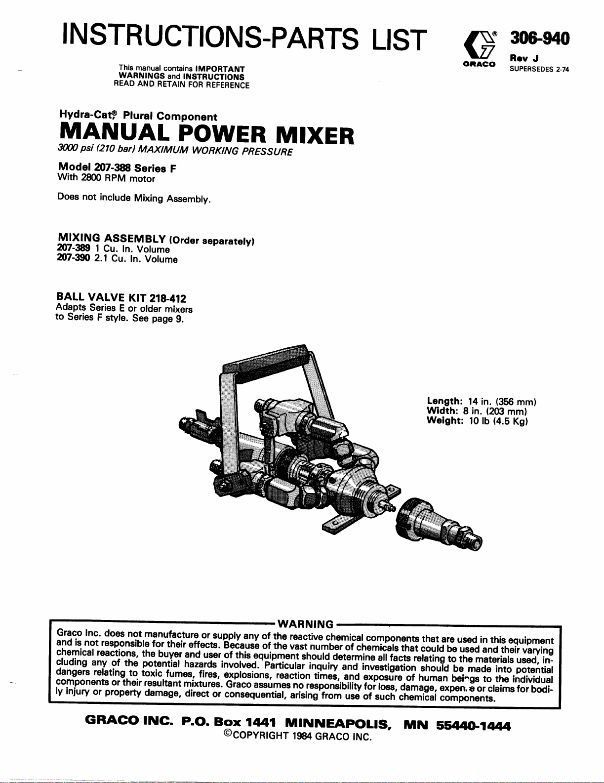
Page 1
Parts
Page 2
General Safety
This equipment generates very high fluid pressure. Spray from
the gun, leaks or ruptured components can inject fluid
through your skin and into your body and cause extremely
serious bodily injury, including the need for amputation. Also,
fluid injected or splashed into the eyes can cause serious
damage.
NEVER point the spray gun or dispensing valve at anyone or at
any part of the body. NEVER put hand or fingers over the
spray tip or nozzle. NEVER try to “blow back” fluid; this is
NOT an air spray system.
ALWAYS follow the Pressure Relief Procedure, below,
before
cleaning or removing the spray tip or nozzle or servicing
any system equipment.
NEVER try to stop or deflect leaks with your hand or body.
Be sure equipment safety devices are operating properly
before each use.
Medical Treatment
If any fluid appears to penetrate your skin, get
EMERGENCY
Tell the doctor exactly what fluid was injected. For treatment
instructions, have your doctor call the
DO NOT TREAT AS A SIMPLE CUT.
MEDICAL CARE AT ONCE .
NATIONAL POISON CENTER NETWORK
(412)681-6869
Pressure Relief Procedure
To reduce the risk of serious bodily injury, including injection,
always follow this procedure whenever the pump is shut off,
when checking or servicing any part of the system, when installing or changing spray tips, and whenever you stop spraying.
1.
Close the mixer material valves.
2.
Open the solvent flush valve(s) and flush until clean.
Spray Gun or Dispensing Valve Safety Devices
Be sure all gun safety devices are operating properly before
each use. Do not remove or modify any part of the gun; this
can cause a malfunction and result in serious bodily injury.
Safety Latch (If your gun is equipped with one)
Whenever you stop spraying, even for a moment, always set
the gun safety latch in the closed or “safe” position, making
the gun inoperative. Failure to set the safety latch can result in
accidental triggering of the gun.
Diffuser (If your gun is equipped with one)
The diffuser breaks up spray and reduces the risk of injection
when the tip is not installed. Check diffuser operation regular-
ly. Follow the Pressure Relief Procedure, below, then
remove the spray tip. Aim the gun into a metal pail, holding
the gun firmly to the pail. Using the lowest possible pressure,
trigger the gun. If the fluid emitted is
regular stream, replace the diffuser immediately.
fip Guard (If your gun is equipped with one)
ALWAYS have the tip guard in place on the spray gun while
spraying. The tip guard alerts you to the injection hazard and
helps prevent accidentally placing your fingers or any part of
your body close to the spray tip.
Trigger Guard (If your gun is equipped with one)
NEVER
guard helps prevent the gun from triggering accidentally if it is
dropped.
Spray Tip or Nozzle Safety
Use
nozzle. If the spray tip or nozzle clogs while spraying, engage
the gun safety latch immediately. ALWAYS follow the
Pressure Relief Procedure and then remove the spray tip to
clean it.
NEVER
pressure is fully relieved and the gun safety latch is engaged.
not
diffused into an ir-
operate the gun with the trigger guard removed. The
extreme caution when cleaning or changing spray tips or
wipe off build up around the spray tip or nozzle until
3.
Shut off the material and solvent pumps.
4. Open the spray gun or dispensing valve to relieve
pressure.
5.
If material has hardened in the hose or mixer, close the
material valve, shut off the material and solvent pumps,
and slow/y loosen the material inlet hose(s) to relieve
pressure, then remove the dispensing hose.
“~%**?.Y” <+ ‘9.y +*i
EQUIPMENT
M/S(JSE
HAZARD ~~~~~~~~~~~~~~~,~;.:-
y+J~~ “‘X :q+&.&&,>:
General Safety
Any misuse of the spray equipment or accessories, such as
overpressurizing, modifying parts, using incompatible
chemicals and materials, or using worn or damaged parts, can
cause them to rupture and result in injection or other serious
bodily injury, fire, explosion or property damage.
NEVER alter or modify any part of this equipment; doing so
could cause it to malfunction.
CHECK all spray equipment regularly and repair or replace
worn or damaged parts immediately.
2
306-940
,:,,~.~~i;:‘::,~~,,~,.,~;,:~:
:;,:~.I:~.‘.~;:~~:,~~,‘,~:.‘,
:., :‘.I:.
< ., .:
‘:$;<I.ty:,;I;;, :‘,.. ‘.;.‘-,“‘.-;:;;~
System Pressure
Never exceed the maximum working pressure of the lowest
rated equipment in your spray system. This manifold has a
3cKx)
psi (210 bar) MAXIMUM WORKING PRESSURE. Be
sure that all fluid and air accessories you add to the spray
system are properly rated to withstand the maximum air and
fluid working pressures of this system.
Material Compatibility
BE SURE that all materials and solvents used are chemically
compatible with the wetted parts shown in the Technical Data
on the back cover. Always read the material and solvent
manufacturer’s literature before using them in this sprayer.
Page 3
HOSE
SAFETY
,;
.,/ .‘y_‘;. :.: ,..: .,‘..:<:.’ y:::’
y: ;,
‘;..;; ,,,.., :K:
Static electricity is created by the high velocity flow of fluid
through the pump and hose. If every part of the spray equip-
ment is not properly grounded, sparking may occur, and the
system may become hazardous. Sparking may also occur
when plugging in or unplugging a power supply cord. Sparks
High pressure fluid in the hoses can be very dangerous. If the
hose develops a pinhole leak, split or rupture due to any kind
of wear, damage or misuse, the high pressure spray emitted
from it can cause an injection injury or other serious bodily injury or property damage.
can ignite fumes from solvents and the fluid being sprayed,
dust particles and other flammable substances, whether you
are spraying indoors or outdoors, and can cause a fire or ex-
plosion and serious bodily injury and property damage. Do not
ALL FLUID HOSES MUST HAVE SPRING GUA’RDSI The
spring guards help protect the hose from kinks or bends at or
close to the coupling which can result in hose rupture.
plug in or unplug any power supply cords in the spray area
when there is any chance of igniting fumes still in the air.
TIGHTEN all fluid connections securely before each use. High
pressure fluid can dislodge a loose coupling or allow high
Grounding
pressure spray to be emitted from the coupling.
To reduce the risk of static sparking, ground the sprayer and
all other spray equipment used or located in the spray area.
CHECK your local electrical code for detailed grounding in-
structions for your area and type of equipment. BE SURE to
ground all of this spray equipment:
NEVER use a damaged hose. Before each use, check entire
hose for cuts, leaks, abrasion, bulging cover, or damage or
movement of the hose couplings. If any of these conditions
exist, replace the hose immediately. DO NOT try to recouple
high pressure hose or mend it with tape or any other device. A
1.
Pump:
use a ground wire and clamp as instructed in your
repaired hose cannot contain the high pressure fluid.
pump instruction manual.
HANDLE AND ROUTE HOSES CAREFULLY. Do not pull on
2.
Fluid hoses:
of 500 feet
grounding continuity. Refer also to Hose Grounding
Continuity.
3.
Spray gun, manifold or dispensing valve: obtain groun-
ding through connection to a properly grounded fluid
hose and sprayer.
use only grounded hoses with a maximum
(150 m)
combined hose length to ensure
hoses to move equipment. Do not use materials or solvents
which are not compatible with the inner tube and cover of the
hose. DO NOT expose the hose to temperatures above
(62OC)
Hose Grounding Continuity
Grace fluid hoses have electrically conductive material on the
surface of the center core of the hose. Other hoses on the
market may have a ground wire extending the length of the
4.
Object being sprayed:
according to local code.
hose. The ground wire can break in use which will destroy the
electrical grounding of the hose.
5.
All
solvent pails
code.
Use on/y
place the pail on a non-conductive surface, such as paper
or cardboard, which interrupts the grounding continuity.
used when flushing, according to local
metalpaik,
which are conductive. Do not
To be sure of continuity, check electrical resistance at least
once a week. Check overall resistance when using multiple
hose assemblies. If the resistance exceeds 29 megohms,
replace it immediately. Ground wire hose may have different
6.
To maintain grounding continuity when flushing or reliev-
ing pressure,
the side of a
always hold a metal part of the gun firmly to
metal
pail, then trigger the gun.
resistance; check supplier.
MOVING PARTS HAZARD
Flushing Safety
Reduce the risk of injection injury, static sparking, or splashing
by following the specific flushing procedure given on page 5 of
this manual. Follow the Pressure Relief Procedure on page
2, and remove the spray tip before flushing. Hold a metal part
of the gun firmly to the side of a
metal
pail and use the lowest
possible fluid pressure during flushing.
Moving parts can pinch or amputate your fingers or other
body parts. KEEP CLEAR of moving parts when starting or
operating the sprayer. Unplug the sprayer and relieve pressure
before checking or servicing the sprayer to prevent it from
starting accidentally.
or below
-4OOF (-4OOC).
16OOF
.
IMPORTANT
United States Government safety standards have been adopted under the Occupational Safety and Health Act. These standards-par-
ticularly the General Standards, Part 1910, and the Construction Standards, Part 1926-should be consulted.
306-W
3
Page 4

INSTALLATION
*_~I.
,;: ,.
, :
~ . .
:.
. .
For assistance in setting up a plural component system,
you should contact
Belmont, Chicago, Illinois 60121-2891, (3121678-7200.
This will help ensure that you select the proper type and
size of equipment for your job.
All inlet connections on this mixer have l/4
threads.
Grace
Fluid Systems, 9451 West
npt(m)
Use an air regulator to control the mixer motor speed.
Install a bleed-type master air valve on the air line to
shut off and relieve air to the mixer motor.
Start and prime the solvent pump and check the
flushing system before connecting the material hoses.
OPERATION i
Determine Motor Air Pressure Setting
Pull the actuating lever (29) back to close the inlet
valves. Then refer to the separate operating instructions
for your proportioning pump, and start the system.
Set the air pressure to the mixer motor at about 30 psi
(2.5 bar). Place a small waste container under the mixer
outlet (A). Open the air valve to start the mixer motor,
then open the material inlet valves. When the container
is full, close the valves.
Increase the air pressure slightly and dispense another
sample. Repeat this procedure five or six times, record-
ing the air pressure setting for each sample. Place
another waste container under the mixer outlet, start
the mixer motor, and open the solvent valve. When
clean solvent comes form the outlet, close and the solvent valve then stop the mixer motor.
Let all samples “cure”,
each one for proper cure. Select the sample which
cured properly at the lowest air pressure and use that
pressure for the mixer air supply. Repeat the test if none
of the samples cured properly.
or harden, completely. Examine
CAUTION
Always use the lowest possible air pressure as this
produces the least amount. of heat created by fric-
tion of the mixing shaft with the motor.
r
4
306-940
I i
Determine Material Pot Life
To test the pot life, use a cup with approximately the
same shape and size as the mixing assembly chamber; 1
cubic inch for Model 207389, or 2.1 cubic inch for
Model 207-390. Start the mixer motor and open the
material valves to fill the container. Close the material
valves and starting timing the reaction.
Flush the mixing chamber with solvent to remove the
mixer material.
When the material starts to gel, check how long the
reaction has taken. This is the operating pot life of your
material. Reduce that time by at least 10% to determine
how long your system can remain idle without flushing
or dispensing material. For example, if the pot life is 11
minutes, then 9 minutes is the maximum time that mixed material should be left in the mixing chamber and
hoses before dispensing or flushing.
NOTE:
ASSEMBLY
If the material pot life is 10 minutes or less,
use the Grace Automatic Power Mixer.
Page 5

a,rarcup
Start the mixer motor before opening the material
valves. Then close the valves before stopping the
motor.
rwsnmg
When you stop dispensing for a short time, close the
mixer material valves and open the solvent flush valve.
Leave the motor running. Point the material outlet into a
waste container, open the dispensing valve and flush
When you stop dispensing for 10 minutes or longer,
stop the mixer motor to prevent heat build up caused by
friction. Do not allow the system to stand idle for more
until the solvent is clean. Close the solvent valve, stop
the motor and open the dispensing valve to relieve
pressure.
than the mixed material pot life.
For longer shutdowns, solvent flush as above, follow
For the most consistent results, always fully open the
actuating lever when dispensing. If a dispensing valve is
used, you can leave the mixer material valves open until
you are ready to flush.
the Pressure Relief Procedure on page 6, then discon-
nect the dispensing hose and equipment from the mixer. Unscrew the adapter (201) from the mixing chamber
and remove the mixing shaft (204). Soak and clean
parts with clean solvent and a stiff brush. Rinse and
Lubrication
blow dry with air. Clean all material off the mixer
chamber. Do not reassemble until you are ready to use
the mixer again.
Solvent may channel through viscous materials and
leave a coating of mixed material on the inner tube of
For automatic mixer motor lubrication, install an air line
lubricator ahead of the motor. For manual lubrication,
your hose. Be sure all material is thoroughly flushed
from the hose after each use.
remove the plug in the air motor head and place 10 to 15
drops of oil into the motor each day. Use only
lightweight machine oil.
Disassemble all other dispensing equipment, as
necessary, and clean thoroughly.
BE SURE AIR
MOTOR IS
LUBRICATED
PROPERLY
204,
306-940
5
Page 6

TROUBLESHOOTING GUIDE
WARNING
To reduce the risk of serious bodily injury,
eluding
checking. or repairing any parts and whenever you
shut down the sytem.
2. Open the solvent flush valve and flush until
3.
4. Shut off the material pumps and solvent
I
injection, follow this procedure before
1
1.. Close the mixer material valves.
clean.
Shut off the air to the mixer motor.
pump.
Open the dispensing valve to relieve pressure.
5.
6. Open any drain valves.
in-
Check all possible causes and solutions before
disassembling the mixer for repair. If problem is still not
corrected, refer to the troubleshooting sections in the
separate manuals supplied with each component in
your system.
PROBLEM
Air motor won’t run
Little or no Part A (Resin) coming
out
Little or no Part B (Catalyst) com- Material supply container
ing out.
Air motor runs but material not
mixed properly.
CAUSE
Not enough air pressure or
volume.
Closed or clogged air valves (42)
or lines.
Hardened material in mixing
chamber.
Material supply container
empty.
Plugged material inlet or check
valve.
Air motor (7) malfunction. Replace.
empn/.
Plugged material inlet (31) or
check (15) valve.
Not enough air pressure or
volume.
Plugged material inlet (31) or
check (15) valve.
SOLUTION
Check. Requires 25 to 30 CFM
at
106
psi (7 bar) for con-
tinuous operation.
Open, clear.
See last section of Service,
page 7. Observe pot life.
Refill, prime system
Clean. Refer to Service.
Refill, prime system.
Clean, refer to Service.
Check, adjust.
Clean. Refer to Service.
Drive shaft (18) broken.
Worn or damaged spline shaft
(B).
Broken or damaged mixing shaft
Replace. Refer to Service.
Replace. Refer to Service.
Replace. Refer to Service.
(204).
Air motor (7) malfunction.
Mixed material won’t flush out. Hardened material in mixing
chamber (202).
Solvent supply container empty.
Solvent not compatible with
material.
Material leaks around packing re- Worn or damaged drive shaft
tainer (16). packings (17).
*Be sure to read and observe the material manufacturer’s literature before using any material In this system.
Replace.
See last section of Service
Observe pot life.
Fill and prime.
Check, correct”
Replace. Refer to Service.
*. . .
6 306-94-o
Page 7

To Inspect or Replace Drive Spline or Mixing Shaft
If mixer motor runs but material is not mixed properly:
Use a spanner wrench to unscrew the connecting hous-
ing retainer nut (23) CLOCKWISE off the air motor-it
has left hand threads. Inspect the spline shaft (B) for
wear or damage and replace if necessary. Also check
the thrust spring (14) and replace if it is weak or broken.
See Fig 4.
Screw the mixing assembly retaining nut (11) COUNT-
ERCLOCKWISE off the head (24) and remove the mix-
ing assembly. Remove the mixing shaft (204) from the
chamber (202). See Figures 5 and 6. Place parts in solvent and clean thoroughly. Inspect parts for wear or
damage. Replace the entire mixing assembly if the mix-
ing chamber is nicked or scored. Check the o-ring (6) in
place on the head (24) and replace if necessary.
To inspect or replace the drive shaft
(18),
clean all
material off the shaft, then loosen the packing nut (19)
and pull the shaft through the back of the connecting
housing. If the shaft is damaged in any way, replace it.
Check the packing contact area for burrs or scratches
which will cause premature packing wear.
To reassemble, install one or two washers (27) between
the spline shaft and air motor to obtain a 0.347 to 0.437
in. (8.8 to 11 .l mm) dimension. Refer to Detail in Fig 4.
Leave the packing nut (19) loose until the mixer is
assembled, then tighten.
Replace Packings
If material leaks around the packing retainer (161, and
tightening the packing nut (19) does not stop it:
Disassemble the mixer as explained above. Turn the
packing nut all the way up against the housing retaining
nut (23). Remove the packing retainer (16). See Fig 5.
Remove the packings carefully, using a suitable hooked
tool. Be careful not to scratch the housing (43). Inspect
the packing retainer gland end. If it is damaged, replace
the retainer.
Insert a new male gland (22) into the housing, then install new packings (17) one at a time, pushing each all
the way into the housing. Install the packing retainer in
the housing (43). Reassemble the mixer, then tighten
the packing nut (19) snugly, just enough to stop
leakage.
0.347” to 0.437”
(8.8 to 11.1 mm)
Fig 5
42’
306-940
7
Page 8

Cleaning and Servicing Inlet or Check Valves
If either the inlet or check valve seems plugged or
damaged:
Remove the actuating lever. Remove and disassemble
the plugged valve. Clean all parts and inspect for wear
or damage, replacing parts as necessary. Lubricate
parts with a light grease and reassemble the valve. Align
the hole in the ball (35) with the hole through the body
MO). Refer to the Parts Drawing.
Unscrew the swivel (30) from the check valve and screw
the check valve seat (15) out of the mixer head (24).
Disassemble the valve and clean all parts. Also clean the
passageway in the head. Check the valve seat (15) for
nicks and replace parts as necessary. Replace the
gasket (26) reassemble and screw into the mixer. Refer
to mixing assembly.
Install the swivel and actuating lever.
If Material Hardens in the Mixing Chamber
Shut off air to the solvent and material supply pumps.
Close the mixer inlet valves and
material inlet hoses to relieve pressure. Then remove
the mixing assembly retaining nut and disconnect the
dispensing hose.
slow/y
loosen the
Tap on the mixing chamber (202) with a piece of wood
or a plastic hammer to break it loose, then pry it off.
Knock out the mixing shaft, if possible, and place parts
in a pail of compatible solvent. If the mixing shaft (204)
will not come out, and there is no solvent available that
will dissolve the material without damaging the parts,
install a complete new mixing assembly. Refer to mixing
assembly .
Completely disassemble the mixer and clean it
thoroughly. Reassemble, using new packings, glands
and any other parts, as necessary. Be sure that no
hardened material remains on any part of the mixer.
FcAuT’oNI
Fig 6,
Be sure to check and then observe the mixed
material
ing in the mixer and resulting in costly damage.
pot life to prevent
material
from harden-
201
0
306-940
Page 9

Model 207-388 Power Mixer
Series F Includes items l-43
42
213-040
MATERIAL INLET
(SEE DETAIL A)
l/4
h
MATERIAL INLET
NPTl
33
BALL VALVE
f
REF PART
NO. NO.
“101823
102-207
“102-310
102-410
102556
“102595
102597
102598
150-707
158-485
164548
167-124
167-125
167-731
167-743
* 167-745
* 167-746
* 167-747
167-761
* 167-762
167-763
* 167-764
DESCRIPTION
BALL, sst; 5/16” dia.; check valve
SETSCREW,
thd sz; l/4” long
CAPNUT, hex; No.
nylon insert
CAPSCREW,
size;
3/8”
RIVET
O-RING, PTFE
MOTOR, air; 2800 RPM
CAPSCREW,
size;
l/2”
PLATE, serial
GASKET, copper
NUT, plain knurled; l-5/8”-18 UNEF
thd size
GRIP, hand; lower, nylon
GRIP, hand; upper, nylon
SPRING, helical compression
SEAT, check valve
RETAINER, packing, female gland
V-PACKING, PTFE
SHAFT, mixer drive
NUT, plain round; l-l/8”-12 UNF-2
thd size; packing nut
GUIDE, spring; check valve
BRACKET, mounting
GLAND, packing; male
sot
hd cup pt; l/4-20
sot
long
long
hd; No. 6-32 thd
sot
hd; No.
lo-32
thd sz;
lo-32
thd
QTY
3
2
3
2
2
1
2
1
1
2
:
i
r,
1
;
1
1
REF PART DESCRIPTION
NO. NO,
167-765
167-766
* 167-770
“168492
170-786
178-747
217561
207-411
213-040
Series B
104893
104892
164-900
178-746
165-274
165-964
178-745
172-094
178-743
165-599
208390
167-767
*Recommended ‘tool box” spare parts. Keep on hand to
reduce down time.
NUT, plain knurled; l-7/16” thd
HEAD, power mixer
SPRING, helical compression, check
valve
GASKET, copper; 7/8” dia.
WASHER, l/2” dia.
SOLVENT VALVE LEVER
ACTUATING LEVER
ADAPTER, swivel union,
3/8
npt(f)
BALL VALVE
Includes items 32-41
.O-RING, PTFE
.O-RING, PTFE
. WASH ER, acetal homopolymer
. BALL, valve
.NIPPLE,
.NUT, stem packing
.STEM,
. SEAT, ball
.HOUSING,
.STEM
BALL VALVE (see 307-068 for parts)
HOUSING, mixer head
adapter, 1/4x
valve
valve
45O;
11/16
thd
QTY
sz
3ow4o
1
z
2
:
3
3
1
z
:
1
2
1
1
1
9
Page 10

4000 RPM AIR MOTOR 102-584
For materials which are more difficult to mix
MIXING ASSEMBLIES
207-389 1 Cu. In. Volume
207-390 2.1 Cu. In. Volume
Includes items 201-205
BALL VALVE KIT 218-412
Adapts Series E and older power mixers to new style
ball valve and actuating lever style. If your mixer is
Series E or older, the material ball valves must be replaced together and a new lever installed as the old parts are
not interchangeable. Kit includes two ball valves,
213-040 and one actuating lever 217561.
201 167-738
202
-f
167-739
167-753
203 167-953
r207-395
205
207494
Model 207-389
Model 207-390
ADAPTER,
3/8
npt(m)
CHAMBER,
CHAMBER, mixing (Model
GASKET, copper
MIXING SHAFT. 2 blade
(Model-267-389)’
MIXING SHAFT, 3 blade
(Model 207-390)
BEARING, end thrust
pipe; 7/8-14(f) to
thd size
mixing (Model 207-389)
~
207-390)
10
204
306-940
Page 11

Page 12

TECHNICAL DATA
All inlets : l/4
Material Outlet :
Air Motor :
Air Requirements :
Wetted Parts :
npt(m)
3/8
npt(m), or
7/8-14-UNF
1 HP; 2800 RPM maximum
25 to 30 CFM at 100 psi (7 bar) continuous operation
Stainless steel, steel, carbon steel; PTFE, Nylon,
Viton
SERVICE INFORMATION
Listed below by the assembly changed are ADDED and
DELETED parts.
ASSEMBLY PART
CHANGED STATUS
I
207-388
Mixer to
Series F
DELETED
ADDED
DELETED
ADDED
DELETED
ADDED
FIEF
PART
NO. NO. NAME
205-643 Lever
28
170-747 Lever
207-394 Lever
29
217-561 Lever
207-875 Valve
31
213-040 Valve
NOTE: ADDED parts are NOT interchangeable with
DELETED parts.
*When ordering replacement ball valve on Series E or
earlier mixers, order Kit No. 217-412 which includes
two new style ball valves and new style actuating
lever.
Grace Inc. warrants all equipment manufactured by it and bearing its
name to be free from defects in material and workmanship under
normal use and service. This warranty extends to the original
purchaser for a period of 12 months from the date of purchase and applies only when the equipment is installed and operated in
accordance with written factory recommendations. This warranty
I
does not cover damage or wear which, in the reasonable judgment of
Grace, arises from misuse, abrasion, corrosion, negligence, accident,
substitution of non-Grace parts, faulty installation or tampering.
This warranty is conditioned upon the prepaid return of the equipment
claimed to be defective for examination by Grace to verify the claimed
defect. If the claimed defect is verified,
free of charge, any defective parts. The equipment will be returned to
the original purchaser transportation prepaid. If inspection of the
equipment does not disclose any defect in workmanship or material,
repairs will be made at a reasonable charge and return transportation
will be charged.
THIS LIMITED WARRANTY IS EXCLUSIVE, AND IS IN LIEU OF
ANY OTHER WARRANTIES (EXPRESS OR IMPLIED) INCLUDING
WARRANTY OF MERCHANTABILITY OR WARRANTY OF
FITNESS FOR A PARTICULAR PURPOSE AND OF ANY NON-
CONTRACTUAL LIABILITIES INCLUDING PRODUCT LIABILITIES
BASED ON NEGLIGENCE OR STRICT LIABILITY. EVERY FORM OF
LIABILITY FOR DIRECT, SPECIAL OR CONSEQUENTIAL
DAMAGES OR LOSS IS EXPRESSLY EXCLUDED AND DENIED.
EQUIPMENT NOT COVERED BY GRACO WARRANTY. Accessories
or components of equipment sold by Grace that are not manufactured
by
the warranty, if any, of their manufacturer.
purchaser with reasonable assistance in making such claims.
with outlet adapter removed
THE GRACO WARRANTY
Grace
will repair or replace
Grace
(such as electric motors, switches, hose, etc.) are subject to
Grace
will provide
Subsidiary and Affiliate Ccmpanier:Canada; England; Switzerland; France; Germany; Hong Kong; Japan
Factory BranchesAtlanta, Dallas, Detroit, Los Angeles, West Caldwell
(N.J.1
GRACO INC. P. 0. Box 1441 MINNEAPOLIS, MN 5544011444
PRINTED IN U.S.A. 30&940 4-67 Revised 5-84
 Loading...