


INSTRUCTIONS-PARTS
LIST
308–781
This
manual contains important
warnings and information.
READ AND KEEP FOR REFERENCE.
INSTRUCTIONS
Husky
715 T
exture Pump
First
choice when
quality counts.
100 psi (0.7 MPa, 7 bar) Maximum Air and Fluid Working Pressure
Model
U.S.
Other U.S. and Foreign Patents Pending
Warnings 2.
Operation 4
Maintenance 5
Troubleshooting 6
Service
Service
Service
Parts
Parts
Technical
Graco Warranty 20.
Graco
239–421, Series A
Patent Nos. 4,789,131 and 4,867,653
Table
. . . . . . . . . . . . . . . . . . . . . . . . . . . . . . . . . . . . .
. . . . . . . . . . . . . . . . . . . . . . . . . . . . . . . . . . . . .
– Air V
– Duckbill V
– Diaphragm
List
. . . . . . . . . . . . . . . . . . . . . . . . . . . . . . . . . . . .
Drawing
Data
Phone Number
of Contents
. . . . . . . . . . . . . . . . . . . . . . . . . . . . . . . . . . .
. . . . . . . . . . . . . . . . . . . . . . . . . . . . . . . .
alve 7.
. . . . . . . . . . . . . . . . . . . . . . . . . . . .
alves 12.
. . . . . . . . . . . . . . . . . . . . . .
. . . . . . . . . . . . . . . . . . . . . . . . .
. . . . . . . . . . . . . . . . . . . . . . . . . . . . . . .
. . . . . . . . . . . . . . . . . . . . . . . . . . . . . . .
. . . . . . . . . . . . . . . . . . . . . . . . . . . . . .
. . . . . . . . . . . . . . . . . . . . . . . . .
13.
16.
17.
19.
20.
Rev. A
GRACO INC. P.O. BOX 1441
MINNEAPOLIS, MN
COPYRIGHT
Graco
Inc. is registered to I.S. EN ISO 9001
1997, GRACO INC.
7323A
55440–1441
Symbols
Warning Symbol
WARNING
This
symbol alerts you to the possibility of serious
injury or death if you do not follow the instructions.
WARNING
EQUIPMENT MISUSE HAZARD
INSTRUCTIONS
Equipment
D
This equipment is for professional use only
D
Read all instruction manuals, tags, and labels before operating the equipment.
D
Use the equipment only for its intended purpose. If you are not sure, call your Graco distributor
D
Do not expose the system to rain. Always store the system indoors.
D
Do not alter or modify this equipment.
misuse can cause the equipment to rupture or malfunction and result in serious injury
Caution Symbol
CAUTION
This
symbol alerts you to the possibility of damage to
or destruction of equipment if you do not follow the
instructions.
.
.
.
D
Check equipment daily
D
Do not exceed the maximum working pressure of the lowest rated component in your system. This
equipment has a
7 bar) maximum air pressure.
D
The system is for use only with water-based simulated acoustic and wall texture materials.
Use fluids and solvents which are compatible with the equipment wetted parts. Refer to the
nical Data
D
Do not use hoses to pull equipment.
D
Route hoses away from traffic areas, sharp edges, moving parts, and hot surfaces. Do not expose
Graco hoses to temperatures above 82_C (180_F) or below –40_C (–40
D
Do not lift pressurized equipment.
D
Comply with all applicable local, state, and national fire, electrical, and safety regulations.
section of all equipment manuals. Read the fluid and solvent manufacturer’s warnings.
. Repair or replace worn or damaged parts immediately
100 psi (0.7 MPa, 7 bar) maximum working pressure at 100 psi (0.7 MPa,
.
_F).
Tech-
TOXIC FLUID HAZARD
WARNING
Hazardous
inhaled, or swallowed.
Know the specific hazards of the fluid you are using.
Store hazardous fluid in an approved container
state and national guidelines.
Always wear protective eyewear
solvent manufacturer
Pipe and dispose of the exhaust air safely
the diaphragm fails, the fluid is exhausted along with the air
fluid or toxic fumes can cause serious injury or death if splashed in the eyes or on the skin,
. Dispose of hazardous fluid according to all local,
, gloves, clothing and respirator as recommended by the fluid and
.
, away from people, animals, and food handling areas. If
.
FIRE AND EXPLOSION HAZARD
Improper
result in a fire or explosion and serious injury
grounding, poor ventilation, open flames or sparks can cause a hazardous condition and
.
Ground the equipment. See the
If there is any static sparking or you feel an electric shock while using this equipment,
ing immediately. Do not use the equipment until you identify and correct the problem.
Grounding
section in instruction manual 308–718.237683
stop pump-
Provide fresh air ventilation to avoid the buildup of flammable fumes from solvents or the fluid
being pumped.
Keep the work area free of debris, including solvent, rags, and gasoline.
Electrically disconnect all equipment in the work area.
Extinguish all open flames or pilot lights in the work area.
Do not smoke in the work area.
Do not turn on or of
Do not operate a gasoline engine in the work area.
f any light switch in the work area while operating or if fumes are present.

Operation
See your system manual for operating instructions.
4 308-781
Maintenance
WARNING
PRESSURIZED EQUIPMENT HAZARD
The equipment stays pressurized until pressure is
manually relieved. To reduce the risk of serious
injury from pressurized fluid, accidental spray from
the gun or splashing fluid, follow this procedure
whenever you
Are instructed to relieve the pressure
Stop pumping
Check or service any system equipment
Install or clean the spray nozzle
Pressure Relief Procedure
1. Shut
2. T
3.
4.
Daily checks
of
f the system.
rigger the gun.
Open the gun air valve, if so equipped.
Disconnect the power source.
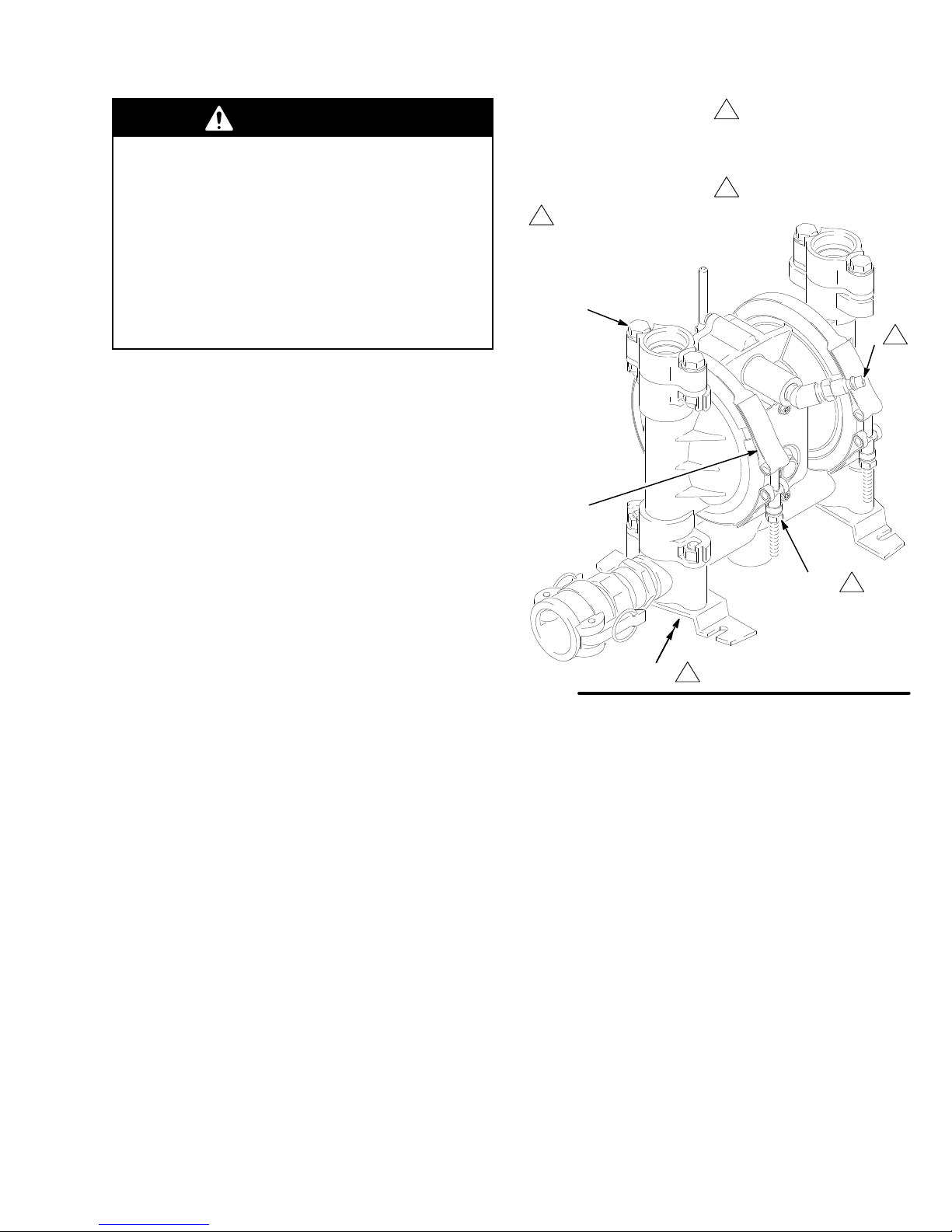
Key
A
Air inlet
110
Clamp nuts
109 Clamps
Add
two drops of machine
oil into air inlet every 50
hours.
59
109
Apply thread lubricant to
bolts, and torque the nuts
(1
10) to 75 to 85 in-lb
(8.5 to 9.6 N.m).
Torque
to 3 to 6 ft-lb
(4 to 8 N-m).
A
Before
each use, check all hoses for wear or damage
and replace as necessary
are tight and leak-free.
. Be sure hose connections
Pump lubrication
After
every 50 hours of fluid pumped, or every month,
remove the quick-disconnect hose from the pump air
inlet (A). Add two drops of machine oil into the air inlet.
Refer to Fig. 1.
Tighten pump’s threaded
connections every six months
Remove
and tighten all threaded connections.
When tightening the clamps (109), apply thread
lubricant to the bolts, and
(1
T
orque the manifold bolts (105) and the adaptor bolts
(59) to 3 to 6 ft-lb (4 to 8 N-m).
the pump from the cart and thoroughly check
be sure
10) to 75 to 85 in-lb (8.5 to 9.6 N.m). See Fig. 1.
to torque the nuts
Fig.
1
105
110
7324A
5308-781
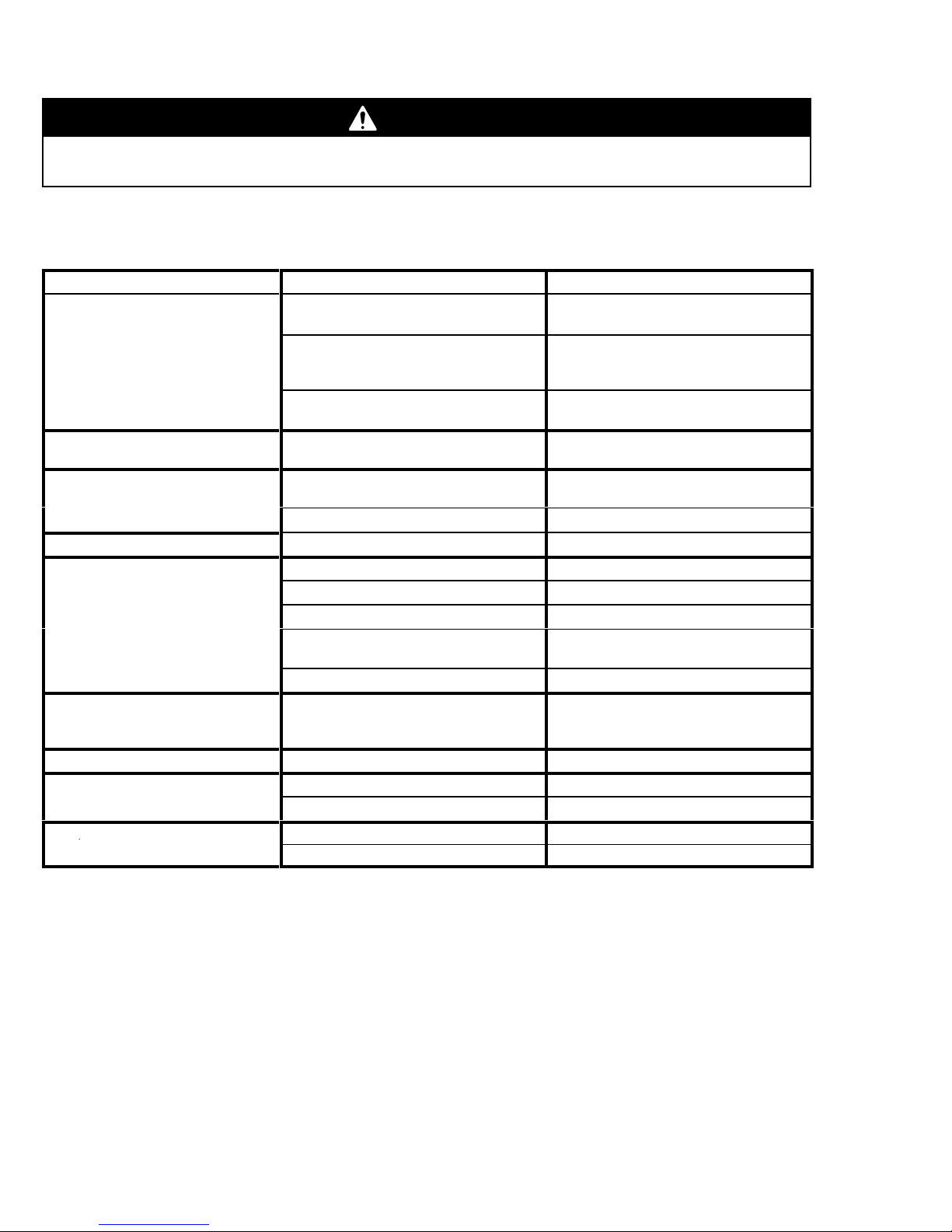
Troubleshooting
p
WARNING
To
reduce the risk of serious injury whenever you are instructed to relieve pressure, always follow the
Pressure Relief Procedure
on page 5.
See the
Troubleshooting
section of instruction manual 308–718 before you proceed with the table below
all possible problems and causes before you disassemble the pump.
PROBLEM CAUSE SOLUTION
Pump will not cycle, or cycles once
and stops.
Pump cycles at stall, or fails to hold
pressure at stall.
Excessive air leakage from exhaust
port, or air exhausts at stall.
Pump operates erratically
Air bubbles in fluid.
Fluid in exhaust air
Pump exhausts air from clamps.
Pump exhausts air near air valve.
Pump leaks fluid from check valves.
. Sticky or leaking duckbill valves (52).
.
Air valve (200) is stuck or dirty.
Broken or damaged springs (209, 212)
and/or valve cup (210) and plate (13).
W
orn or broken detent link (213).
Leaky duckbill valves (52).
W
orn air valve cup (210) or plate (13). Repair or replace.
W
orn shaft seals (30).
Suction line is loose.
Diaphragm (60) is ruptured.
Loose manifold (102) or adapters (57)
Manifold o-rings (50) or adapter o-rings
(53) are leaking.
Loose outer diaphragm plates (1
Diaphragm (60) is ruptured, or dia
phragm plates (1
cracked.
Clamps (109) are loose.
Air valve screws (10) are loose. Tighten screws.
Air valve o-ring (201) is damaged.
Adaptors (57) are loose.
W
orn or damaged o-rings (50).
18, 1
16) are loose or
18). T
-
Disassemble, clean, and lube air valve.
See page 9.
Repair or replace components, or re
place complete air valve (kit 237–683).
See page 7.
Replace detent link and ball (207), or
complete air valve (kit 237–683).
Repair or replace.
Repair or replace.
Repair or replace.
Tighten.
Replace.
T
ighten bolts (59, 105).
Replace.
ighten.
Replace diaphragm and/or tighten
plates.
T
ighten clamps.
Inspect; replace.
T
ighten bolts (59).
Inspect; replace.
. Check
-
See page 12.
See page 9.
See page 14.
See page 12.
See page 13.
See page 5.
See page 12.
See page 14.
See page 14.
See page 5.
See page 7.
See page 8.
See page 12.
See page 12.
6 308-781
 Loading...