


Repair/Parts
Husky™ 2150e
Electric-Operated Diaphragm Pump
2–Inch pumps with electric drive for fluid transfer applications.
Not approved for use in explosive atmospheres or hazardous locations unless otherwise stated. See
Approvals page for more information. For professional use only.
Important Safety Instructions
Read all warnings and instructions in this manual and in your Husky
2150e Operation manual.
Maximum working pressure: 100 psi
(0.69 MPa, 6.9 bar)
See page 7 for approvals.
Save these instructions.
3A5131E
EN
PROVEN QUALITY. LEADING TECHNOLOGY.
Contents
Related Manuals ................................................ 2
Warnings ........................................................... 3
Configuration Number Matrix............................... 6
Ordering Information........................................... 8
Troubleshooting.................................................. 9
Repair................................................................ 11
Pressure Relief Procedure............................ 11
Check Valve Repair ..................................... 11
Diaphragm Repair........................................ 13
Related Manuals
Manual Number Title
3A4068
Husky™ 2150e Electric-Operated Diaphragm Pump, Operation
Center Section Repair .................................. 15
Leak Sensor Repair ..................................... 20
Replace the Compressor.............................. 21
Torque Instructions ............................................. 22
Torque sequence......................................... 22
Parts.................................................................. 24
Kits and Accessories.................................... 34
Technical Data ................................................... 35
2
3A5131E

Warnings
Warnings
The following warnings are for the setup, use, grounding, maintenance, and repair of this equipment. The
exclamation point symbol alerts you to a general warning and the hazard symbols refer to procedure-specific
risks. When these symbols appear in the body of this manual or on warning labels, refer back to these
Warnings. Product-specifi c hazard s y mbo ls and warni ngs not cov ered in this section may appea r throughout
the body of this manual where applicable.
WARNING
ELECTRIC SHOCK HAZARD
This equipment must be grounded. Improper grounding, setup, or usage of the system can
cause electric shock.
• Turn off and remove power before disconnecting any cables and before servicing or installing
equipment. For cart-mounted models, unplug the power cord. For all other units, disconnect
power at the main switch.
• Connect only to ground ed power source.
• A l l electrical wiring must be done b y a qu al ifi ed electrici an and comply wi th all local c odes
and regulations.
• Wait five minutes for capacitor disc harge before opening equipment.
FIRE AND EXPLOSION HAZARD
Flammable fumes, such as solvent and paint fumes, in
or solvent flowing through the equipment can cause static sparking. To help prevent fire and
explosion:
• Use equipment only in well ventilated area.
• Eliminate all ignition sources; such as pilot lights, cigarettes, portable electric lamps, and
plastic drop cloths (potential static arc).
• Ground all equipment in the work area. See
• Keep work area free of debris, including solvent, rags and gasoline.
• Do not plug or unplug power cords, or turn power or light switches on or off when flammable
fumes are present.
• Use only grounded hoses.
•
Stop operation immediately
equipment until you identify and correct the problem.
• K ee p a working fire ext ingui sh er in the work area.
Static charge may build up on plastic parts during c leaning and could discharge and ignite
flammable vapors. To help prevent fi re and explosion:
• Clean plastic parts only in well ventilated area.
• Donotcleanwithadrycloth.
• Do not operate electrostatic guns in equipment work area.
if static sparking occu rs or you feel a shock.Do not use
Grounding
work area
instructions.
canigniteorexplode.Paint
3A5131E 3

Warnings
WARNING
PRESSURIZED EQUIPMENT HAZARD
Fluid from the equipment, leaks, or rup tured compo nents ca n splash in the eyes or on skin
and cause serious injury.
• Follow the
cleaning, checkin g, or servicing equipment.
• Tighten all fluid connections before operating the equipment.
• Check hoses, tubes, and couplings daily. Replace worn or damaged parts immedia tely.
EQUIPMENT MISUSE HAZARD
Misuse can cause death or serious injury.
• Do not operate the unit when fatigued or under the influence of drugs or alcohol.
• Do not exceed the maximum working pressure or temperature rating of the lowest rated
system component. See
• Use fluids and solvents that are compatible with equipment wetted parts. See
in all equipment manuals. Read fluid and solvent manufacturer’s warnings. For complete
information about your material, request Safety Data Sheet (SDS) from distributor or retailer.
• Turn off all equipment and follow the
• Check equipment daily. Repair or replace worn or damaged parts immediately with genuine
manufacturer’s replacement parts only.
• Do not alter or modify equipment. Alterations or modifications may void agency approvals
and create safety hazards.
• Make sure all equipment is rated and approved for the environment in which you are using it.
• Use equipment only for its intended purpose. Call your distributor for information.
• Route hoses and cables away from traffic areas, sharp edges, moving parts, and hot surfaces.
• Do not kink or over bend hoses or use hoses to pull equipment.
• Keep children and animals away from work area.
• Comply with all applicable safety regulations.
Pressure Relief Procedure
Technical Data
when you stop spraying/dispensing and before
in all equipment manuals.
Technical Data
Pressure Relief Procedure
when equipment is not in use.
PRESSURIZ E D ALUMINUM PARTS HAZARD
Use of fluids that are incompatible with aluminum in pressurized equipment can caus e serious
chemical reaction and equipment rupture. Failure to follow this warning can result in death,
serious injury, or property damage.
• Do not use 1,1,1-trichloroethane, methylene chloride, other halogenated hydrocarbon
solvents or fluids containing such solvents.
• Do not use chlorine bleach.
• Many other fluids may contain chemicals that can react with aluminum. Contact your material
supplier for compatibility.
4
3A5131E

Warnings
WARNING
THERMAL EXPANSION HAZARD
Fluids subjected to heat in confined spaces, including hoses, c an create a rapid rise in pressure
due to the thermal expansion. Over-pressurization can result in equipment rupture and serious
injury.
• Openavalvetorelievethefluidexpansionduringheating.
• Replace hoses proactively at regular intervals based on your operating conditions.
PLASTIC PARTS CLEANING SOLVENT HAZARD
Many solvents can degrade plastic parts and cause them to fail, which could c ause se rious
injury or property damage.
• Use only compatible water-based solvents to clean plastic structural or pressure-contain ing
parts.
•See
Technical Data
solvent manufacturer’s Safety Data Sheet (SDS) and recommendations.
in this and all other equipment instruction manuals. Read fluid and
TOXIC FLUID OR FUMES HAZARD
Toxic fluids or fumes can cause serious injury or death if splashed in the eyes or on skin,
inhaled, or swallowed.
• Read Safety Data Sheet (SDS) to know the specific hazards of the fluids you are using.
• Store hazardous fluid in approved containers, and dispose of it according to applicable
guidelines.
BURN HAZARD
Equipment surfaces and fluid that’s heated can become very hot during operati on. To avoid
severe burns:
• Do not touch hot fluid or equipment.
PERSONAL PROTECTIV E EQUIPMENT
Wear appropriate protective equipment when in the work area to help prevent serious injury,
including eye injury, hearing loss, inhalation of toxic fumes, and burns. This protective
equipment includes but is not limited to:
• Protective eyewear, and hearing protection.
• Respirators, protective clothing, and gloves as recommended by the fluid and solvent
manufacturer.
3A5131E 5

Configuration Number Matrix
Configuration Number Matrix
Check the identification plate (ID) for the
Configuration Numb er of your pump. Use the
following matrix to define the com pon ent s of your
pump.
Sample Configuration Number:
2150
Pump
Model
NOTE:
Pump Wetted Section
2150
AEA
Wetted
Section
Material
Some combinations are not possible. Please refer to Ordering Information, page 8 .
Material
Aluminum
A
Conductive
C
Polypr
PVDF
F
Cast Iron
I
Polypropylene
P
Stainless Steel
S
Drive
opylene
Center
Section
Material
2150A-E,A04AA1TPTPTP- -
04
Gear Box
and Com-
pressor
Drive TypeCenter Section
Material
Electric
E
A
S
A
Motor
Aluminum
Stainless Steel
A1
Fluid Covers and
Manifolds
TP TP TP
Seats
Gearbox and
Compressor
No Gearbox or
94
Compressor
High Speed Gear
04
Ratio
High Speed
05
Gear Ratio/120V
Compressor
High Speed
06
Gear Ratio/240V
Compressor
Mid Speed Gear
14
15
16
24
2
26
5
o
Rati
Mid Speed
Gear Ratio/120V
Compressor
Mid Speed
Gear Ratio/240V
Compressor
Low Speed Gear
atio
R
Low Speed
Gear Ratio/120V
Compressor
Low Speed
Gear Ratio/240V
Compressor
Balls Diaphragms
Motor
A
C
D
G
--
Manifold
O-Rings
Standard
Induction Motor
ATEX Induction
Motor
Flameproof
Induction Motor
No Motor
6 3A5131E

Configuration Number Matrix
Fluid Covers and
Manifolds
A1
A2
C2
F2
P2
S1
S2
S5-1
S5-2
I1
I2
Aluminum, npt
Aluminum, bsp
Conductive
polypropylene,
end flange
PVDF, end
flange
Polypropylene,
end flange
Stainless steel,
npt
Stainless steel,
bsp
Stainless steel,
center flange,
horizontal outlet
Stainless steel,
center flange,
vertical outlet
Cast Iron,
standard ports,
npt
Cast Iron,
standard ports,
bsp
Seat Material
Geolast
GE
Polypropy-
PP
lene
PVDF
PV
Santoprene
SP
316 Stainless
SS
Steel
TPE
TP
Ball Material Diaphragm Material
Acetal
AC
Polychloroprene
CW
Weighted
Geolast
GE
PTFE
PT
440C Stainless
SD
Steel
Santoprene
SP
TPE
TP
GE
PT
SP
TP
Geolast
PTFE/EPDM
2–Piece
Santoprene
TPE
Manifold
O-Rings
––
Model does
not use o-rings
PTFE
PT
✦ Aluminum, cast iron, conductive
polypropylene, and stainless steel pumps with
motor code C are certified t o:
✚ Aluminum, cast iron, conductive
polypropylene, and stainless steel pumps with
motor code G are certifi ed to:
★ Motors coded D are ce rtifi ed to:
All Models (except gearbox and compressor
codes 05, 15, and 25, or motor code D)are
certified to:
Approvals
II 2 G Ex h d IIB T3 Gb
II2GExhIIBT3Gb
Class I, Div 1, Group D, T3B
Class II, Div 1, Group F & G, T3B
3A5131E
7
Ordering Information
Ordering Information
To Find Your Nearest Distributor
1. Visit www.graco.com.
2. Click on
To Specify the Configuration of a New Pump
Please call your distributor.
OR
Where to Buy
and use the
Distributor Locator.
Use the
Online Diaphragm Pump Selector Tool at www.graco.com.
To Order Replacement Parts
Please call your distributor.
Go to the
Process Equipment Page.
8 3A5131E
Troubleshooting
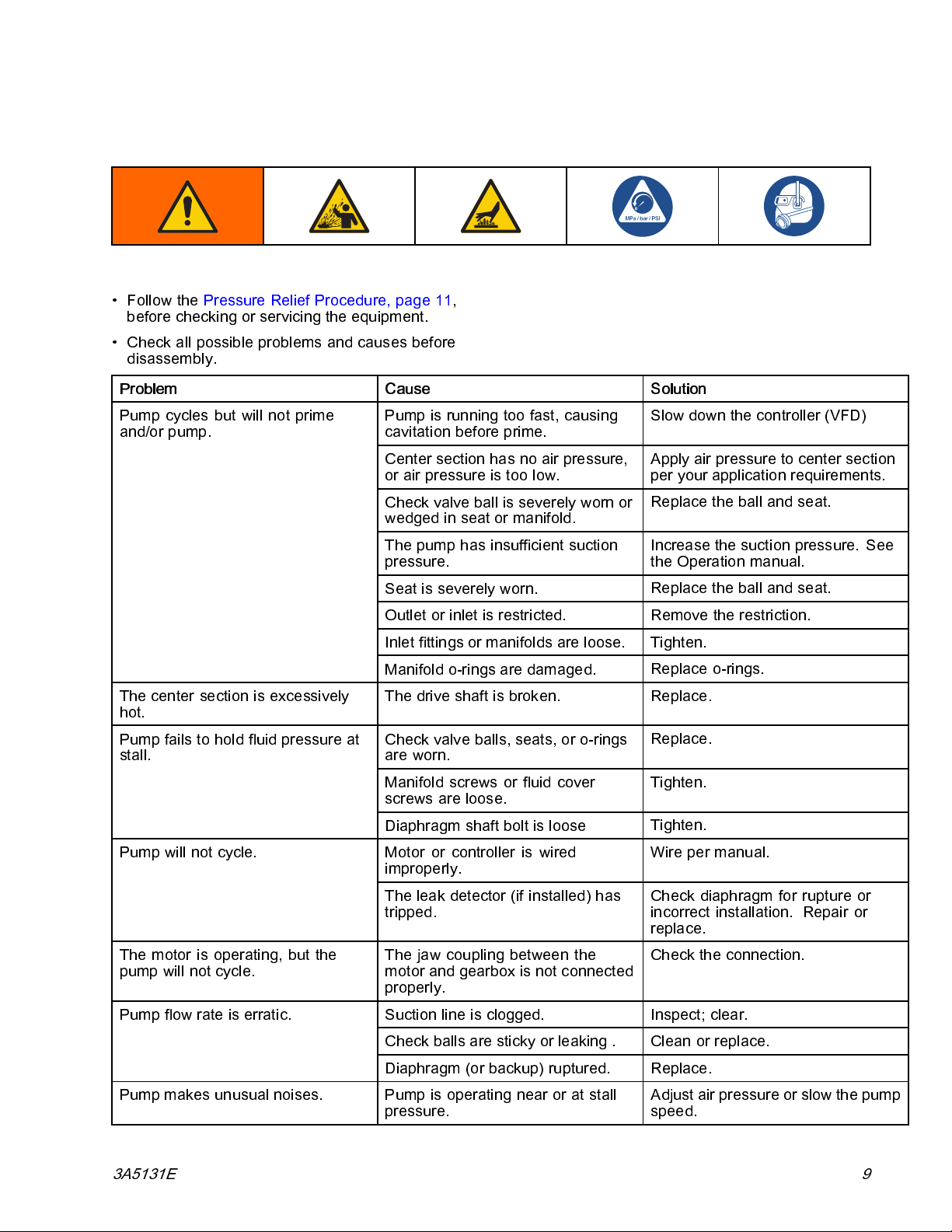
•FollowthePressure Relie f Procedure, page 11,
before checking or servicing the equipment.
• Check all possible problems and causes before
disassembly.
Problem Cause Solution
Troubleshooting
Pump cycles but will not prime
and/or pump.
The center section is excessively
hot.
Pumpfailstoholdfluidpressureat
stall.
Pump is running
cavitation before prime.
Center section has no air pressure,
or air pressure is too low.
Check valve ball is severely worn or
wedged in seat or manifold.
The pump has
pressure.
Seat is severely worn.
Outlet or inlet is restricted. Remove the
Inlet fitt
Manifold o-rings are damaged.
The drive shaft is broken.
Check valve balls, seats, or o-rings
are worn.
Manifold screws or fluid cover
screws are loose.
Diaphragm shaft bolt is loose
Motor or controller is wired
improperly.
ings or manifolds are loose. Tighten.
too fast, causing
insufficient suctio n
Slow down the co
Apply air pressure to center section
per your application requirements.
Replace the ball and seat.
Increase th
the Operation manual.
Replace the ball and seat.
Replace o-rings.
Replace.
Replace.
n.
Tighte
Tighten.
Wire per manual.Pump will not cycle.
ntroller (VFD)
e suction pressure. See
restriction.
The leak detector (if installed) has
ped.
trip
The motor is operating, but the
pump will not cycle.
mp flow rate is erratic.
Pu
Pump makes unusual noises. Pump is operating near or at stall
3A5131E 9
The jaw coupling between the
motor and gearbox is not connected
properly.
ction line is clogged. Inspect; clear.
Su
Check balls are sticky or leaking . Clean or replace.
Diaphragm (or backup) ruptured.
pressure.
Check diaphragm for rupture or
rrect installation. Repair or
inco
replace.
Check the connection.
Replace.
Adjust air pressure or slow the pump
speed.
Troubleshooting
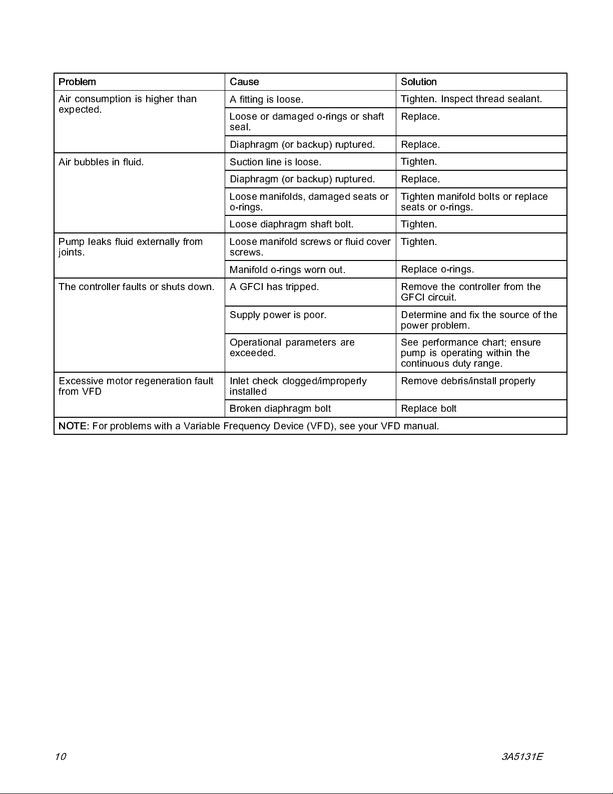
Problem Cause Solution
Air consumption is higher than
expected.
Air bubbles in fluid.
Pump leaks fluid externally from
joints.
The controller faults or shuts down.
Excessive motor regeneration fault
from VFD
Afittingisloose.
Loose or damaged o-rings or shaft
seal.
Diaphragm (or backup) ruptured.
Suction line is loose.
Diaphragm (or backup) ruptured.
Loose manifolds, damaged seats or
o-rings.
Loose diaphragm shaft bolt.
Loose manifold screws or fluid cover
screws.
Manifold o-rings worn out.
A GFCI has tripped. Remove the controller from the
Supply power is poor. Determine and fix the so urce of the
Operational parameters are
exceeded.
Inlet check clogged/improperly
installed
Tighten. Inspect thread sealant.
Replace.
Replace.
Tighten.
Replace.
Tighten manifold bolts or replace
seats or o-rings.
Tighten.
Tighten.
Replace o-rings.
GFCI circuit.
power problem.
See performance chart; ensure
pump is operating within the
continuous duty range.
Remove debris/install properly
NOTE:
Broken diaphragm bolt Replace bolt
For problems with a Variable Frequency Device (VFD), see your VFD manual.
10 3A5131E
Repair
Repair
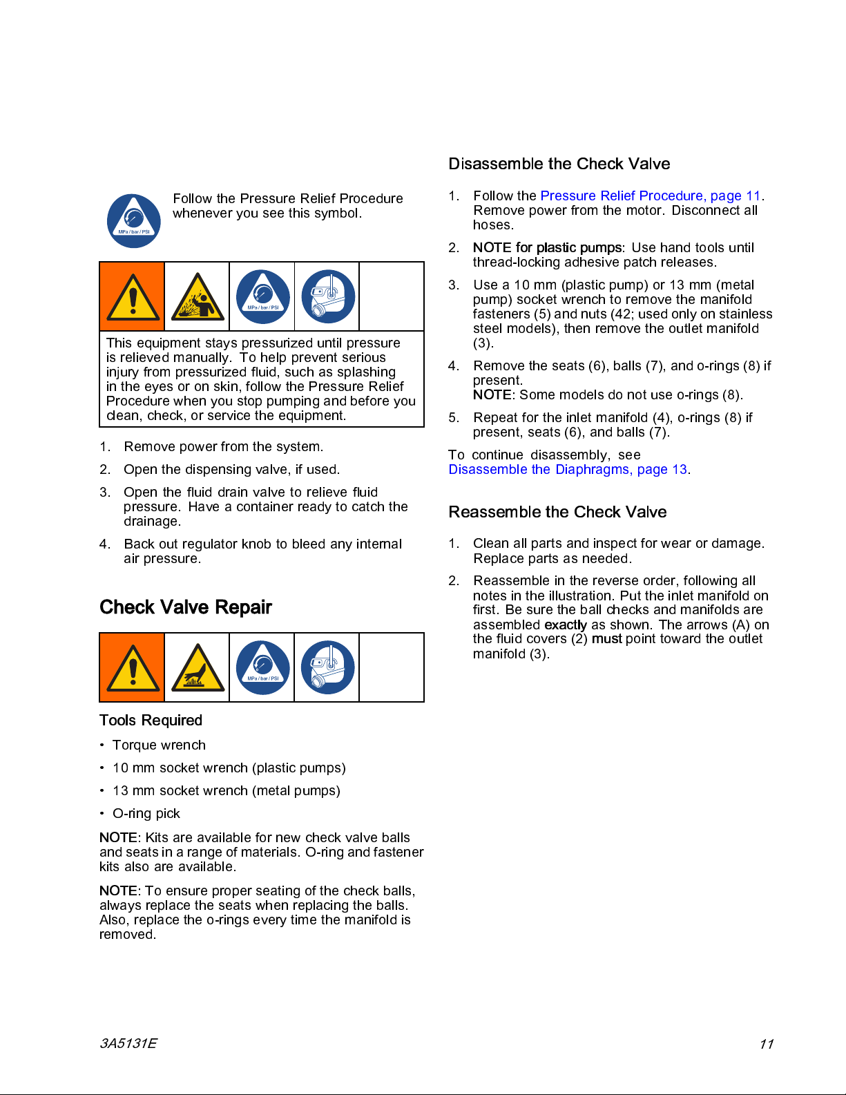
Pressure Relief Procedure
Follow the Pressure Relief Procedure
whenever you see this symbol.
This equipment stays pressurized until pressure
is relieved manually. To help prevent serious
injury from pressurized fluid, such as splashing
in the eyes or on skin, follow the Pressure Relief
Procedure when you stop pumping and before you
clean, check, or service the equipment.
1. Remove power from the system.
2. Open the dispensing valve, if used.
3. Open the fluid drain valve to relieve fluid
pressure. Have a container ready to catch the
drainage.
4. Back out regulator knob to bleed any internal
air pressure.
Check Valve Repair
Disassemble the Check Valve
1. Follow the Pressure Relief Procedure, page 11.
Remove power from the motor. Disconnect all
hoses.
2.
NOTE for plastic pumps:
thread-locking adhesive patch releases.
3. Use a 10 mm (plastic pump) or 13 mm (metal
pump)socketwrenchtoremovethemanifold
fasteners (5) and nuts (42; used only on stainless
steel models), then remove the outlet manifold
(3).
4. Remove the seats (6), balls (7), and o-rings (8) if
present.
NOTE:
5. Repeat for the inlet manifold (4), o-rings (8) if
present, seats (6), and balls (7).
To continue disassembly, see
Disassemble the Diaphragms, page 13.
Some models do not use o-rings (8).
Use hand tools until
Reassemble the Check Valve
1. Clean all parts and inspect for wear or damage.
Replace parts as needed.
2. Reassemble in the reverse order, following all
notes in the illustration. Put the inlet manifold on
first. Be s ure the b al l checks and m ani fol ds are
assembled
the fluid covers (2)
manifold (3).
exactly
as shown. The a rrows (A) on
must
point toward the outlet
Tools Required
• Torque wrench
• 10 mm socket wrench (plastic pumps)
• 13 mm socket wrench (metal pumps)
• O-ring pick
NOTE:
and seats in a range of materials. O-ring and fastener
kits also are available.
NOTE:
always replace the seats when replacing the balls.
Also, replace the o-rings every time the manifold is
removed.
3A5131E
Kits are available for new check valve balls
To ensure proper seating of the check balls,
11

Repair
12
Check valve assembly, aluminum model shown
Apply me di um-s treng th (blue) thread lock er. Torque to the value specified for you r pump. See
1
Torque Instructions, page 22.
w (A) must point toward outlet manifold
Arro
2
Notusedonsomemodels.
3
Stainless steel models include nuts (42).
4
3A5131E
 Loading...