


Repair/Parts
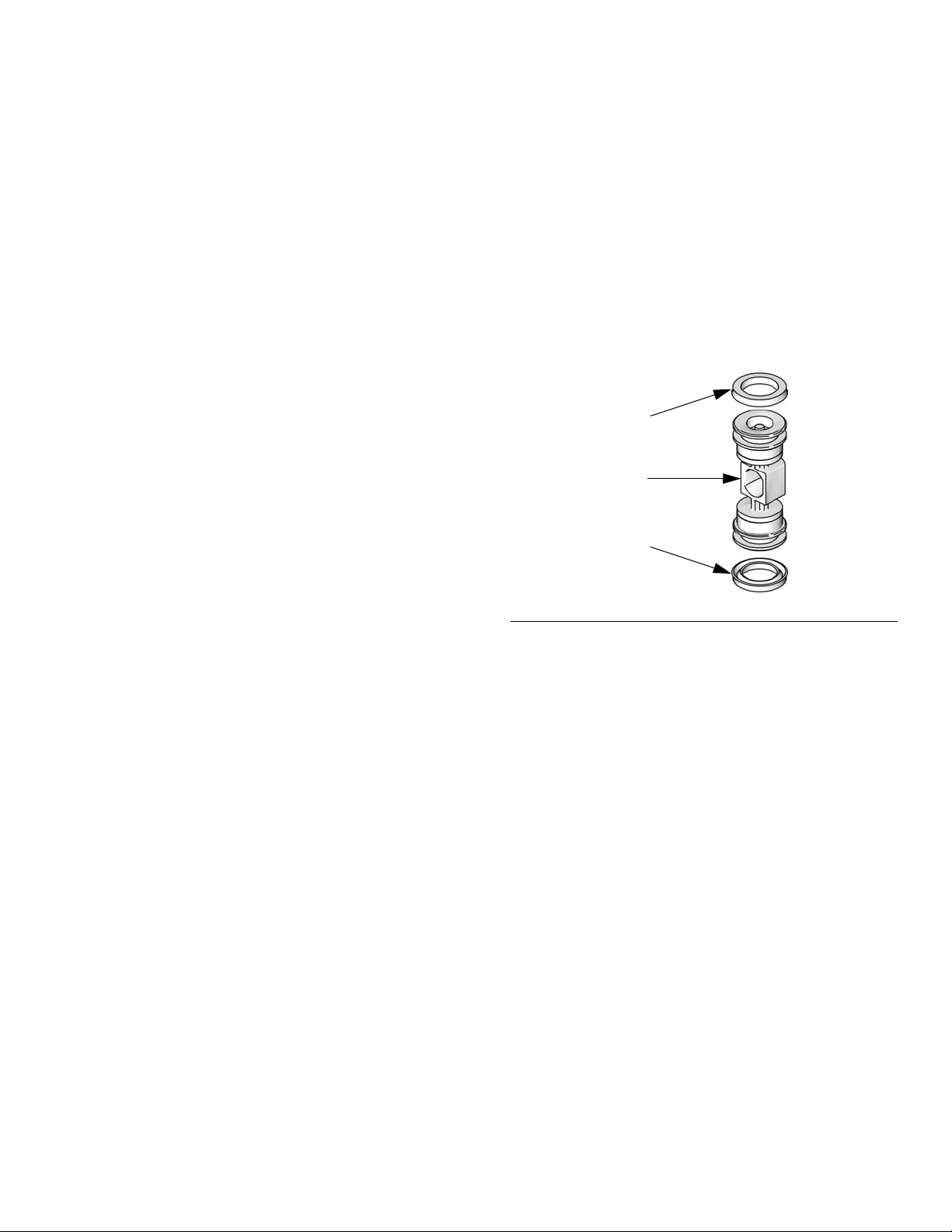
Center
Flange
ti13844a
ti13843a
End
Flange
1050P Polypropylene
1050C Conductive
Polypropylene
1050F PVDF
Important Safety Instructions
Read all warnings and instructions in this manual.
Save these instructions.
1050S Stainless Steel
1050H Hastelloy
ti14342a
1050A Aluminum
ti13946a
®
Husky
1050 Air-Operated
Diaphragm Pump
1-inch pump with modular air valve for fluid transfer applications.
For professional use only.
See page 4 for model information, including approvals.
125 psi (0.86 MPa, 8.6 bar) Maximum Fluid Working Pressure
125 psi (0.86 MPa, 8.6 bar) Maximum Air Input Pressure
313435ZAA
EN

Related Manuals
Contents
Related Manuals . . . . . . . . . . . . . . . . . . . . . . . . . . . 2
To Find Your Nearest Distributor . . . . . . . . . . . . . . 3
To Specify the Configuration of a New Pump . . . . 3
To Order Replacement Parts . . . . . . . . . . . . . . . . . 3
Distributor Note . . . . . . . . . . . . . . . . . . . . . . . . . . . . 3
Pump Matrix . . . . . . . . . . . . . . . . . . . . . . . . . . . . . . . 4
ATEX Certifications . . . . . . . . . . . . . . . . . . . . . . . . . 5
Warnings . . . . . . . . . . . . . . . . . . . . . . . . . . . . . . . . . 5
Troubleshooting . . . . . . . . . . . . . . . . . . . . . . . . . . . 8
Repair . . . . . . . . . . . . . . . . . . . . . . . . . . . . . . . . . . . 10
Pressure Relief Procedure . . . . . . . . . . . . . . . . 10
Repair or Replace Air Valve . . . . . . . . . . . . . . . 10
DataTrak . . . . . . . . . . . . . . . . . . . . . . . . . . . . . . 13
Check Valve Repair . . . . . . . . . . . . . . . . . . . . . 14
Diaphragms and Center Section . . . . . . . . . . . . 15
Torque Instructions . . . . . . . . . . . . . . . . . . . . . . 18
Related Manuals
Manual Description
Parts . . . . . . . . . . . . . . . . . . . . . . . . . . . . . . . . . . . . 20
Parts/Kits Quick Reference . . . . . . . . . . . . . . . . 21
Center Section . . . . . . . . . . . . . . . . . . . . . . . . . . 22
Air Valve and Data Monitoring . . . . . . . . . . . . . . 24
Fluid Covers and Manifolds . . . . . . . . . . . . . . . . 26
Seats and Check Ball . . . . . . . . . . . . . . . . . . . . 28
Diaphragms . . . . . . . . . . . . . . . . . . . . . . . . . . . . 29
Seat, Check Ball, and Diaphragm Kits . . . . . . . 31
Manifold O-Rings . . . . . . . . . . . . . . . . . . . . . . . . 32
DataTrak . . . . . . . . . . . . . . . . . . . . . . . . . . . . . . 32
Accessories . . . . . . . . . . . . . . . . . . . . . . . . . . . . 32
Technical Data . . . . . . . . . . . . . . . . . . . . . . . . . . . . 33
Graco Standard Husky Pump Warranty . . . . . . . . 36
Graco Information . . . . . . . . . . . . . . . . . . . . . . . . . 36
312877
313597
313598
313840
406824
406825
406826
Husky 1050 Air-Operated Diaphragm Pump, Operation
Husky 1050A UL-Listed Diaphragm Pump, Operation
Husky 1050A CSA-Compliant Diaphragm Pumps, Operation
DataTrak, Instructions/Parts
Pulse Count Kits, Instructions
Reed Switch with Solenoid Kits, Instructions
Torque Instructions (Manifolds and Fluid Covers)
2 313435ZAA

To Find Your Nearest Distributor
To Find Your Nearest Distributor
1. Visit www.graco.com.
2. Click on Where to Buy and use the Distributor Locator.
To Specify the Configuration of a New Pump
Please call your distributor.
OR
Use the Online Diaphragm Pump Selector Tool at
www.graco.com.
To Order Replacement Parts
Please call your distributor.
Distributor Note
1. To find part numbers for new pumps or kits, use the Online Diaphragm Pump Selector Tool.
2. To find part numbers for replacement part s:
a. Use the configuration number from the ID plate on the pump. If you only have the Graco 6-digit part num-
ber, use the selector tool to find the corresponding configuration number.
b. Use the Configuration Number Matrix on the next page to understand which parts are described by each
digit.
c. Refer to the main Parts illustration and to the Parts/Kits Quick Reference. Follow the page references on
these two pages for further ordering information, as needed.
3. Please call Graco Customer Service to order.
313435ZAA 3

Pump Matrix
CONFIGURATION NO.PART NO. SERIAL NO.
SERIESDATE CODE
MAX WPR PSI-bar
MADE IN
ID
ti14103a
Pump Matrix
Check the identification plate (ID) for the Configuration Number of your
pump. Use the following matrix to define the components of your pump.
Sample Configuration Number: 1050A-PA01AA1SSBNBNPT
1050 A P A01A A1 SS BN BN PT
Pump
Size
Wetted
Section
Material
Drive
Identifier
Center
Section and
Air Valve
Fluid
Covers and
Manifolds
Seats Balls Diaphragms Manifold
O-Rings
Pump
Size
1050 A Aluminum P
1050 C Conductive
1050 F PVDF A01D Remote
1050 H‡ Hastelloy A01E Optional FKM Seals C2 Conductive polypropylene, end
1050 P Polypropylene AC1A CSA-Compliant
1050 S‡ Stainless Steel AU1A UL-Listed; Fuel
, ‡, or : See ATEX Certifications, on page 5.
Contains pressure relief valve
Wetted Section
Material
Polypropylene
Drive
Identifier
Pneumatic
Center Section and
Air Valve Material
A01A Standard A1 Aluminum, standard ports, inch
A01B Pulse Count A2 Aluminum, standard ports, metric
A01C DataTrak C1 Conductive polypropylene,
Aluminum
AU3A UL-Listed; Fuel
C01A Standard H1 Hastelloy, standard ports, inch
Conductive
Polypropylene
Polypropylene
C01B Pulse Count H2 Hastelloy, standard ports, metric
C01C DataTrak P1 Polypropylene , center flange
C01D Remote P2 Polypropylene, end flange
P01A Standard S1 Stainless steel, standard ports,
P01B Pulse Count
P01C DataTrak S2 Stainless steel, standard ports,
P01D Remote
Air
Valve/Monitoring
transfer
dispense
Fluid Covers and Manifolds
center flange
flange
F1 PVDF, center flange
F2 PVDF, end flange
inch
metric
Stainless steel, center flange,
S5-1
horizontal outlet port
Stainless steel, center flange,
S5-2
vertical outlet port
Check Valve Seats Check Valve Balls Diaphragm Manifold O-Rings
AC Acetal AC Acetal BN Buna-N — Models with
AL Aluminum BN Buna-N CO Polychloroprene Overmolded
BN Buna-N CR Polychloroprene Standard FK FKM Fluoroelastomer
FK FKM Fluoroelastomer CW Polychloroprene Weighted GE Geolast
GE
Geolast
®
FK FKM Fluoroelastomer PO PTFE/EPDM Overmolded
Buna-N, FKM
Fluoroelastomer or TPE
seats do not
use o-rings.
PP Polypropylene GE Geolast PS PTFE/Santoprene Two-Piece PT PTFE
PV PVDF PT PTFE PT PTFE/EPDM Two-Piece
SP
Santoprene
SS 316 Stainless Steel SS 316 Stainless Steel TP TPE
®
SP Santoprene SP Santoprene
TP TPE TP TPE
4 313435ZAA
ATEX Certifications
All 1050A (Aluminum) and
1050C (Conductive Polypropylene)
pumps are certified:
II 2 GD c IIC T4
‡ 1050S (Stainless Steel) and 1050H
(Hastelloy) pumps with aluminum or
conductive polypropylene centers are
certified:
II 2 GD c IIC T4
DataTrak and Pulse Count are
certified:
0359
II 1 G
Ex ia IIA T3 Ga
ITS13ATEX27862X
9902471
Class I, Div. 1,
Group D T3A
ATEX Certifications
Warnings
The following warnings are for the setup, use, grounding, maintenance, and repair of this equipment. The exclamation point symbol alerts you to a general warning and the hazard symbol refers to procedure-specific risk. When
these symbols appear in the body of this manual, refer back to these Warnings. Additional, product-specific warnings
may be found throughout the body of this manual where applicable.
WARNING
FIRE AND EXPLOSION HAZARD
Flammable fumes, such as solvent and paint fumes, in work area can ignite or explode. To help prevent
fire and explosion:
• Use equipment only in well ventilated area.
• Eliminate all ignition sources; such as pilot lights, cigarettes, portable electric lamps, and plastic drop
cloths (potential static arc).
• Keep wor k area free of debris, including solvent, rags and gasoline.
• Do not plug or unplug power cords, or turn power or light switches on or off when flammable fumes
are present.
• Ground all equipment in the work area. See Grounding instructions.
• Use only grounded hoses.
• Hold gun firmly to side of grounded pail when triggering into pail.
• If there is static sparking or you feel a shock, stop operation immediately. Do not use equipment
until you identify and correct the problem.
• Keep a working fire extinguisher in the work area.
Static charge may build up on plastic parts during cleaning and could discharge and ignite flammable
materials and gases. To help prevent fire and explosion:
• Clean plas tic parts in a well ventilated area.
• Do not clean with a dry cloth.
• Do not operate electrostatic guns in equipment work area.
313435ZAA 5
Warnings
WARNING
EQUIPMENT MISUSE HAZARD
Misuse can cause death or serious injury.
• Do not operate the unit when fatigued or under the influence of drugs or alcohol.
• Do not exceed the maximum working pressure or temperature rating of the lowest rated system
component. See Technical Data in all equipment manuals.
• Use fluids and solvents that are compatible with equipment wetted parts. See Technical Data in all
equipment manuals. Read fluid and solvent manufacturer’s warnings. For complete information
about your material, request MSDS from distributor or retailer.
• Do not leave the work area while equipment is energized or under pressure. Turn off all equipment
and follow the Pressure Relief Procedure in this manual when equipment is not in use.
• Check equipment daily. Repair or replace worn or damaged parts immediately with genuine manufacturer’s replacement parts only.
• Do not alter or modify equipment.
• Use equipment only for its intended purpose. Call your distributor for information.
• Route hoses and cable s away from traffic areas, sharp edges, moving parts, and hot surfaces.
• Do not kink or over bend hoses or use hoses to pull equipment.
• Keep children and animals away from work area.
• Comply with all applicable safety regulations.
PRESSURIZED EQUIPMENT HAZARD
Fluid from the gun/dispense valve, leaks, or ruptured components can splash in the eyes or on skin and
cause serious injury.
• Follow Pressure Relief Procedure in this manual, when you stop spraying and before cleaning,
checking, or servicing equipment.
• Tighten all flu id connections before operating the equipment.
• Check hoses, tubes, and couplings daily. Replace worn or damaged parts immediately.
THERMAL EXPANSION HAZARD
Fluids subjected to heat in confined spaces, including hoses, can create a rapid rise in pressure due to
the thermal expansion. Over-pressurization can result in equipment rupture and serious injury.
• Open a valve to relieve the fluid expansion during heating.
• Replace hoses proactively at regular intervals based on your operating conditions.
PRESSURIZED ALUMINUM PARTS HAZARD
Use of fluids that are incompatible with aluminum in pressurized equipment can cause serious chemical
reaction and equipment rupture. Failure to follow this warning can result in death, ser ious inj ury, or prop erty damage.
• Do not use 1,1,1-trichloroethane, methylene chloride, other halogenated hydrocarbon solvents or
fluids containing such solvents.
• Many other fluids may contain chemicals that can react with aluminum. Contact your material
supplier for compatibility.
PLASTIC PARTS CLEANING SOLVENT HAZARD
Use only compatible water-based solvents to clean plastic structural or pressu re-conta ining parts. Many
solvents can degrade plastic parts and cause them to fail, which could cause serious injury or property
damage. See Technical Data in this and a ll other equipment instructio n manuals. Read fluid and so lvent
manufacturer’s warnings.
6 313435ZAA

Warnings
WARNING
TOXIC FLUID OR FUMES HAZARD
Toxic fluids or fumes can cause serious injury or death if splashed in the eyes or on skin, inhaled, or
swallowed.
• Read MSDS’s to know the specific hazards of the fluids you are using.
• Route exhaust away from work area. If diaphragm ruptures, fluid may be exhausted with air.
• Store ha zardous fluid in approved containers, and dispose of it according to applicable guidelines.
BURN HAZARD
Equipment surfaces and fluid that’s heated can become very hot during operation. To avoid severe
burns:
• Do not touch hot fluid or equipment.
PERSONAL PROTECTIVE EQUIPMENT
You must wear appropriate protective equipment when operating, servicing, or when in the oper ating
area of the equipment to help protect you from serious injury, including eye injury, inhalation of toxic
fumes, burns, and hearing loss. This equipment includes but is not limited to:
• Cloth ing and respirator as recommended by the fluid and solvent manufacturer
• Protective eyewear, gloves, and hearing protection.
313435ZAA 7
Troubleshooting
Troubleshooting
Problem Cause Solution
Pump cycles but will not prime. Pump is running too fast, causing
cavitation before prime
Check valve ball severely worn or
wedged in seat or manifold.
Seat severely worn. Replace ball and seat . See pa g e 14 .
Outlet or inlet clogged. Unclog.
Inlet or outlet valve closed. Open.
Inlet fittings or manifolds loose. Tighten.
Manifold o-rings damaged. Replace o-rings. See page 14.
Pump cycles at stall or fails to hold
pressure at stall.
Pump will not cycle, or cycles once
and stops.
Pump operates erratically. Clogged suction line. Inspect; clear.
Worn check valve balls, seats, or
o-rings.
Air valve is stuck or dirty. Disassemble and clean air valve.
Check valve ball severely worn and
wedged in seat or manifold.
Pilot valve worn, damaged, or
plugged.
Air valve gasket damaged. Replace gasket. See page 10.
Check valve ball is wedged into seat
due to overpressurization.
Dispensing valve clogged. Relieve pressure and clear valve.
Air tubing is plugged
(remote air control models).
Sticky or leaking check valve balls. Clean or replace. See page 14.
Diaphragm (and backup) ruptured. Replace. See page 15.
Restricted exhaust. Remove restriction.
Pilot valves damaged or worn. Replace pilot valves. See page 15.
Air valve damaged. Replace air valve. See page 10.
Air valve gasket damaged. Replace air valve gasket. See
Air supply erratic. Repair air supply.
Exhaust muffler icing. Use drier air supply or use low ice
Lower air inlet pressure.
Replace ball and seat. See page 14.
Replace. See page 28.
See page 11. Use filtered air.
Replace ball and seat. See page 14.
Replace pilot valve. See page 15.
Install pressure relief kit. See Acces-
sories, page 32.
Clear tube.
page 10.
muffler (Graco part 102656).
8 313435ZAA

Troubleshooting
Problem Cause Solution
Air bubbles in fluid. Suction line is loose. Tighten.
Diaphragm (and backup) ruptured. Replace. See page 15.
Loose manifolds, damaged seats or
manifold o-rings.
Diaphragm shaft bolt o-ring dam-
Tighten manifold bolts or replace
seats or o-rings. See page 14.
Replace o-ring.
aged.
Pump cavitation. Reduce pump speed or suction lift.
Loose diaphragm shaft bolt. Tighten.
Exhaust air contains fluid being
pumped.
Diaphragm (and backup) ruptured. Replace. See page 15.
Loose diaphragm shaft bolt. Tighten or replace. See page 15.
Diaphragm shaft bolt o-ring dam-
Replace o-ring. See page 15.
aged.
Moisture in exhaust air. High inlet air humidity. Use drier air supply.
Pump exhausts excessive air at
stall*.
Worn air valve cup or plate. Replace cup and plate. See page 11.
Damaged air valve gasket. Replace gasket. See page 10.
Damaged pilot valve. Replace pilot valves. See page 15.
Worn shaft seals or bearings. Replace shaft seals or bearings. See
page 15.
Air tubing is damaged or loose
Replace tubing or secure connection.
(remote air control models).
Remote air pressure is higher than
pump air pressure (remote air control
Regulate remote pilot air pressure to
be equal to or less than main air.
models).
Pump leaks air externally. Air valve or fluid cover screws loose. Tighten.
Diaphragm damaged. Replace diaphragm. See page 15.
Air valve gasket damaged. Replace gasket. See page 10.
Remote air pressure is higher than
pump air pressure (remote air control
Regulate remote pilot air pressure to
be equal to or less than main air.
models).
Pump leaks fluid externally from
joints.
Loose manifold screws or fluid cover
screws.
Tighten manifold screws or fluid
cover screws. See page 18.
Manifold o-rings worn out. Replace o-rings. See page 14.
Pump leaks fluid externally through
manifold or fluid cover.
Excessive pump speed or inlet
starvation.
Replace manifold and reduce pump
speed or improve pump feed.
* A small amount of air will exhaust during stall if the pump is stopped while in the process of changing over. This is
normal. If desired, Valve Upgrade Kit 24K224 can be installed to minimize air exhausting.
313435ZAA 9
Repair
WARNINGWARNINGWARNING
WARNING
ti14094a
ti14095a
Aluminum Model
Shown
109
Repair
SPECIAL CONDITIONS FOR SAFE USE
Equipment must comply with the following
conditions to avoid a hazardous condition
which can cause fire or explosion.
• All label an d marking material must be
• The ele ctronic monitoring system is
cleaned with a damp cloth (or equivalent).
required to be grounded. See Grounding
instructions in your pump operation manual.
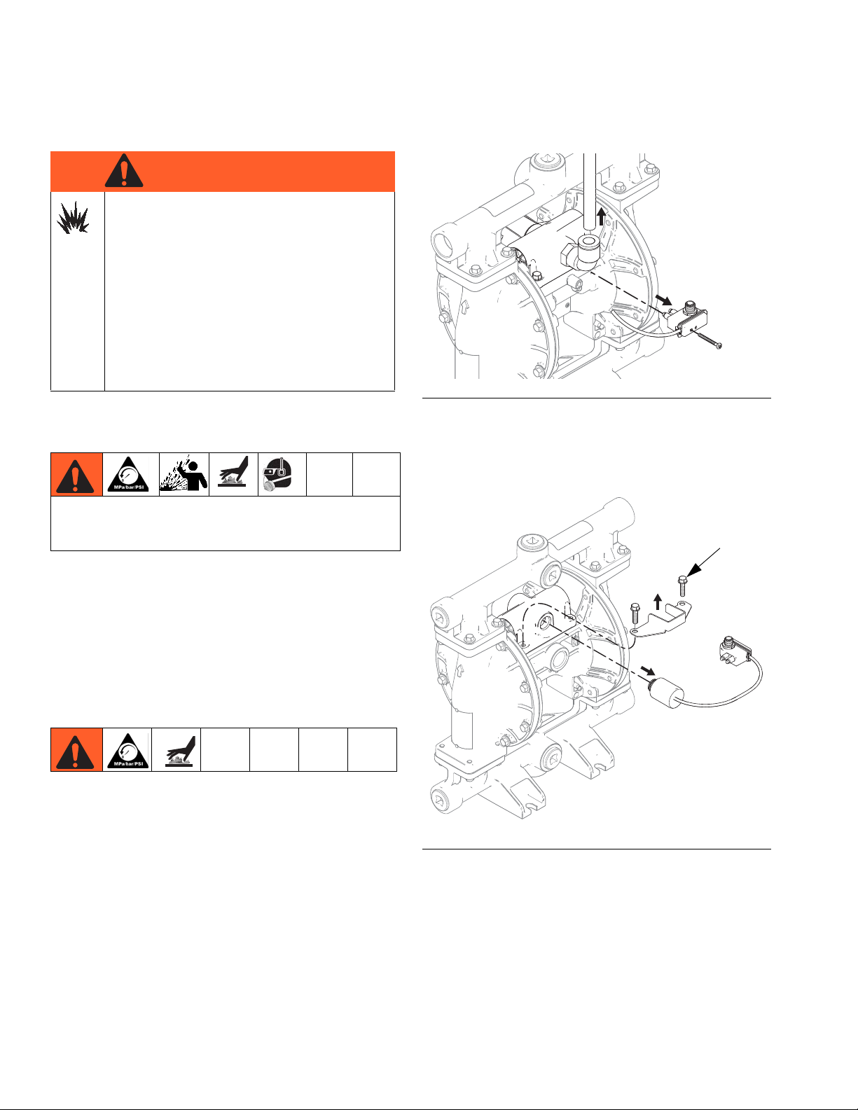
FIG. 1. Reed switch assembly and air line removal
Pressure Relief Procedure
Trapped air can cause the pump to cycle unexpectedly, which could result in serious injury from splashing.
1. Shut off the air supply to the pump.
2. Open the dispensing valve, if used.
3. Open the fluid drain valve to relieve fluid pressure.
Have a container ready to catch the drainage.
Repair or Replace Air Valve
Replace Complete Air Valve
1. Stop the pump. Relieve the pressure. See Pressure
Relief Procedure in previous section.
4. For motors with DataTrak: Remove two screws
and the solenoid bracket. Pull the solenoid out of
the air valve.
F
IG. 2. Solenoid removal
2. Disconnect the air line to the motor.
3. For motors with Pulse Count or DataTrak:
Remove screw to disconnect the reed switch
assembly from the air valve.
10 313435ZAA
5. Remove screws (109, metal pumps) or nuts (112,
plastic pumps). Remove the air valve and gasket
(108).
6. To repair the air valve, go to Disassemble the Air
Valve, step 1, in next section. To install a replacement air valve, continue with step 7.
7. Align the new air valve gasket (108) on the center
housing, then attach the air valve. See Torque
Instructions, page 18.
Repair
Lips face down
Lips face up
208†
208†
202
ti12754a
8. For motors with DataTrak: Remember to reattach
the solenoid bracket and the solenoid.
9. For motors with Pulse Count or DataTrak: Use
screw to attach the reed switch assembly to the new
air valve. Reconnect cable.
10. Reconnect the air line to the motor.
Replace Seals or Rebuild Air Valve
NOTE: Repair kits are available. See page 25 to order
the correct kit(s) for your pump. Air Valve Seal Kit parts
are marked with a †. Air Valve Repair Kit parts are
marked with a . Air Valve End Cap Kit parts are
marked with a .
Disassemble the Air Valve
1. Perform steps 1-5 under Replace Complete Air
Valve, page 10.
2. See F
IG. 4. Use a Torx screwdriver (T8 for alumi-
num centers, T9 for plastic centers) to remove two
screws (209). Remove the valve plate (205),
cup assembly (212-214), spring (211), and detent
assembly (203).
Reassemble the Air Valve
NOTE: Apply lithium-based grease whenever instructed
to grease.
1. Use all parts in the repair kits. Clean other parts and
inspect for damage. Replace as needed.
2. Grease the detent cam (204) and install into housing (201).
3. Grease the u-cups (208) and install on the piston
with lips facing toward the center of the piston.
3. Pull the cup (213) off of the base (212). Remove the
o-ring (214) from the cup.
4. See F
each end of the air valve. Use the piston (202) to
push the end caps (207, 217) out of the ends.
Remove end cap o-rings (206). If pump model is
equipped with a runaway protection solenoid, also
remove the solenoid release button (218) and
o-ring (219).
5. Remove the u-cup seals (208) from each end of the
piston (202), then remove the piston. Remove the
detent cam (204) from the air valve housing (201).
IG. 4. Remove the retaining ring (210) from
IG. 3. Air valve u-cup installation
F
4. Grease both ends of the piston (202) and install it in
the housing (201), with the flat side toward the cup
(212). Be careful not to tear u-cups (208) when sliding piston into housing.
5. Standard or Pulse Count models (no runaway
protection solenoid): Grease new o-rings (206)
and install on the end caps (207). Install the end
caps into the housing.
DataTrak models (with runaway protection solenoid): Orient the air valve so the air inlet faces for-
ward. Grease and install new o-ring (206) on
right-side end cap (207). Grease and install new
o-ring (206) and the solenoid release button (218)
and o-ring (219) on left-side end cap (217). Install
the end caps into the housing.
6. Install a retaining ring (210) on each end to hold end
caps in place.
313435ZAA 11
 Loading...