

Page 1

f';
""'it
;
;,1:":
':..-
,
.
...
.
--i.:r**s&..
4il
l
^.r;:.1:; .
.:
i:f:t'l
'
s-ffiffirs
INSTRUCTI@;N
L!S
T
ORACO
First
choice when
quality
cguits.'*
308-479
,
Rev.
G
\
Supersedes Rev. A
and PCNs B td E
'
(includes
Rev. F)
1
G
T
;
.r,,Ti,'
.---.:-'
;
ALUMINUM AND STAINLESS STEEL
!
''n,Husky
*'
1040
Air-Operated
.
:,.t.
i
J
.,;
I
:.
l;r,f
:.;
;'
Di,aphrcigm
,Pumps
120
psi (0.84
MPi,'8.4 bar)-:AttaxiiAuq
Fluid WorXing
Pressure
120
psi
(0.84
MPa,
8.4
ba\
Maximum Air lnput Pressure
lr
I
(
,t
'-1
'
*Model
No, D73-_
Aluminum Pumps
:
*Modet
tto. oza-T stainless steel
Fr-p=
*NOTE:
Referto
the Pump'Matrix on
page
22 to
determine the Model
No.
of
your pump.
US
and Foreign Patents Pending
1
ii
i'''
/.
C€
,"ii:-glr'"**
.UE
'
--*f*',:
,
.1''
r.
..:
).\ l.'':
:
*
Aluminum
Model Shown
v2632
GRACO INC.
,.,,s
.
...
i,.\
4:!
"(
P.O. BOX'.I2t41
MINNEAPOLIS,
MN
5540-1441
[,
r1a_i
rr
,
*..,@cgflYRtcHT
1994, GRACO
tNC.
..
--*-
-:9raco
lirc. is registered
to l.S. EN ISO 9001
.\.!
;:li!
-
j..'
.{
Y'
-
-!
.'l
'.tir.-;-'.
'
-
.;.]5.i:.i;-:'. ...i.
'..
This manual
contains important
warnings and information.
READ AND
KEEP FOR REFERENCE.
-
INSTRUCNONS
_",'m
-'
Page 2

t
,\
Table
of
Contents
Safety
Warnings
Symbols
lnstallation,..,
Qperation:....
Maintenance . . .
Troubleshooting
Service,
Pump Matrii.. .
Repair Kit Matrix
Parts .
Dimensional Drawings . :.. :. :.. i. . :.
Technical Data and
Performance
Chart
Warranty
Graco Phone Number
Warning Symbol
This
symbol
alerts
you
to the
possibility
of serious
injury or death if
you
do not follow the instructions.
'Caution
Symbot
This
symbolalerts
you
to the
possibility
of damage to
or destruction of equipment if
you
do not follow the
instructions.
*
'Ji1'"
Symbols
r ' o1'
,ltt
2
2
4
10
11
"
12
14
22
23
24
28
29
32
32
[W
A
CEUTION
EQUIPMENT MISUSE HAZARD
Equipment misuse
can cause
the
equipment
to'rupture
or
malfunction
and
result
in serious injury.
o
This
equipment is
for
professional
use
only.
.
Read all
instruction
manuals, tags, and labels before
operating the equipment.
o
Use the equipment only for its
intended
purpose.
lf
you
are not sure, call
your
Graco
distributor:
o
Do
not alter
or
modiff this
equipment.
.
Check equipment daily. Repair or replace worn or damaged
parts
immediately.
o
Do not
exceed
the maximum working
pressure
of
the lowest
rated component in
your
system.
This
equipment
has a 120
psi (0.84
MPa,8.4 bar) maximum
working
pressure
at 120
psi
(0.84
MPa,
8.4
bar) maximum incoming air
pressure.
o
Use
nuiOs
and solvents which are compatible with the equipment wetted
O"nr.
*"r", to
the
Tech-
nical Data seclion of all equipment manuals. Read the fluid and
solvent manufacturer's wam-
i
ings.
i
o
Do
not
use 1,1,1-trichloroethane,
methylene
chloride, other halogenated hydrocarbon
solvents or
fluids
containing such solvents
in
pressurized
aluminum equipment.
Such
use
could
result
in
a
chemical reaction, with the
possibility
of explosion
.
Do not use hoses to
pull
equipment.
o
Route hoses away from traffic areas, sharp edges, moMng
parts,
and hot
surfaces. Do not ex-
pose
Graco
hoses
to
temperatures
above 82'C
(180'D
or below
*40"C
(*40"D.
o
Do not lift
pressurized
equipment.
.
Comply
with
all
applicable local,
state, and national fire, electrical, and
safety
regulations.
2
308-479
Page 3

I
?
a
-
A
N
ii*til*u
#fl\
TOXIC FLUID
HAZARD
Hazardous
fluid
or.toxic
fumes
can cause serious injury or death if
splashed in the
eyes or on the
'r
skin, inhaled,
or swallowed.
.
Know
the specific hazards
of
the fluid
you
are using.
.
Store hazardous fluid in an
approved container. Dispose
of
hazardous
fluid according to all local,
state and nationalguidelines.
:
.
Always wear
protective
eyewear,
gloves,
clothing
and respirator
as recommended
by the
fluid
and solvent manufacturer.
.
o
Pipe and dispose
of the exhaust air safely, away fom
people,
animals, and food handling
areas.
lf the diaphragm fails, the fluid
is exhausted along with the air.
See Air Exhaust
Ventilation on
page
8.
ilH:::;il::::]l*ffi:,
names
orsparks can cause,
r,,.",.0o,"
conoitiqn ano
result in a fire
or explosion and serious injury.
o
Ground the
equipment. Referto Grounding on
page
4.
o
lf
there is any static
sparking or
you
feel an
electric.shock while using this
equipment, stop
pumping
immediately. Do not use the
equipment
until
you
identiff and
correct
the
problem.
I
o
Provide fresh air ventilation to
avoid the buildup of flammable fumes from
solvents or the fluid
being
sprayed.
.
Pipe and dispose
of
the
exhaust.air safely, away,fom,all'iourees of ignition. lf the'diaphragm'
fails, the fluid is
exhausted
along
with the air. See Air Exhaust Ventilation
on
page
8.
o
Keep the work area free
of
debris, including
solvent,
rags,
and
gasoline.
l'
.
Electrically disconnect all
equipment
in the
work area.
j
'i
o
Extinguish all
open
flames
or
pilot
lights in
the work area.
l
o
Do not
smoke in the work area.
:
:
,
"
i
o
Do not turn
on or off
any light
switch
in the
work area while operating or if fum'es are
present.
o
Do not
operate
a
gasoline
engine in the work area.
,
nt
N,/
m
C
Ui:
.t
308-479 3
Page 4

.l
lnstal,lation
General lnformation
.
The Typical lnstallations shown
in
Figs.
24 are
only
guides
for selecting and installing system
components. Contact
your
Graco distributor
for
assistance in
planning
a system
to
suit
your
needs.
o
Always
use
Genuine Graco
Parts and Accessories.
Referto Product Data Sheet 305-588.
o
Reference numbers and letters in
parentheses
refer
to the callouts
in the figures and the
parts
lists on
pages
24-25.
o'
Aluminum Husky 1040 Pump
Model No.239-823,
with straight-thread manifolds,
is available and can
be
ordered separately.
Grounding
To
reduce the risk
of
static"sparking,
ground
the
pump
and
all
oth'er equipment
used or located
in
the
pumping
area. Check
your
local
electrical
code for detailed
grounding
instructions for
your
area
and type of
equipment. Ground
all
of
this equipment.
o
Pump:
Connect
a
ground
wire and
clamp
as shown
in Fig. 1. Loosen the
grounding
lug locknut
(VV)
and
washer
(X).
lnsert
one end of a
12
ga
(1.5
mm2)
minimum
ground
wire
(Y)
into the slot in the
lug
(4
and tighten the locknut securely. Connect
the
clamp
end of the
ground
wire to a true earth
ground.
Order
Part No.
222-011 Ground
\Mre and Clamp.
Z
x
W
Fig. 1
02646
o
Air and fluid hoses: Use
only
grounded
hoses with
a
maximum
of 500
ft
(150
m)
combined
hose
length to
ensure
grounding
continuity.
o
Air
compresson
Follow
the
manufacturer's
recommendations.
o
All
solvent
pails
used when flushing: Follow the
local code. Use only metal
pails,
which are
conductive.
Do not
place
the
pail
on a
non-conductive surface, such
as
paper
or
cardboard,
which interrupts the
grounding
continuity.
.
Fluid
supply container:
Follow thg local,code
.-1.,,s
1u.li.
*1!
4
Y
+
TOXIC FLUID HAZARD
Hazardous fluid or toxic
fumes
can
cause
serious injury or
death if splashed
in the eyes or on
the
skin,
inhaled, or
swallowed.
1. Read TOXIC FLUID HAZARD on
page
3
2. Use
fluids and
solvents
which are compatible
with
the
equipment
wetted
parts.
Refer
to the
Technica! Data section of
all equipment manu-
als. Read the
fluid
and solvent
manufacturer's
warnings.
W
nt
Nl/
FIRE AND EXPLOSION
HAZARD
This
pump
must be
grounded.
Before
operating the
pump, ground
the system
as explained below.
Also, read the sec-
tion FIRE AND EXPLOSION
HAZARD,
on
page
3.
W
4 308-479
Page 5

!nstallation
Mountings
A
CEUTION
The
pump
exhaust air
may
contain
contaminants
Ventilate to a remote area if the
contaminants
could affect
your
fluid
supply. See Air
Exhaust'
Ventilation on
page
8.
1.
Be sure the mounting surface
can support the'
weight of the
pump,
hoses, and
accessories, as
well as the stress
caused during operation.
2.
For
all mountings, be sure the
pump
is bolted
directly to the mounting
surface.
3. For ease of operation and
service, mount the
pump
so
the
air
valve
cover
(2),
air inlet, and fluid
inlet and
outlet
ports
are easily accessible.
4. Rubber Foot Mounting Kit
236452 is available to
reduce noise and vibration
during operation.
Air Line
lnstall the air line accessories
as shown in Figs.
24 on
pages
6 and 7. Mount these
accessories
on
the wall
or on a bracket. Be sure the air line
supplying the accessories
is
grounded.
a. lnstall an air regulator
(C)
and
gauge
to control
the fluid
pressure.
The fluid
outlet
pressure
will
be the same as the setting of
the air
regulator.
b.
''
Lbcate one bleed-type mlster air
valve
(B)
close to the
pump
and use it to relieve trapped
air. See the WARNING above. Locate the
other
master air valve
(E)
upstream from
all
air
line
accessories
and
use it to isolate them
during cleaning and repair.
c. The air line filter
(F)
removes harmful dirt and
.
moisture from the
compressed air supply.
2. lnstall
a
grounded,
flexible
air
hose
(A)
between
the accessories
and lhe 112 npt(f)
pump
air
inlet
(N).
See
Fig.5.
Use a minimum
3/8'(9.5
mm) lD
air hose.
Screw an air line
quick
disconnect
coupler
(D)
onto
the
end of the air hose
(A),
and
.
screw
the mating
fitting into the
pump
air inlet
snugly. Do not
connect the coupler
(D)
to the fitting
until
you
are ready
to operate the
pump.
Fluid
Suction
Line
1.
Use
grounded
fluid
hoses. The
pump
fluid inlet
(R)
is 1" npt(f).
See Fig. 5. Screw the fluid fitting
into
the
pump
inlet
securely.
2. lf the fluid inlet
pressure
to the
pump
is more than
25o/o
of
lhe
outletworking
pressure,
the ballcheck
valves will not
close
fast
enough, resulting in
inefiicient
pu
mp operation.
3. At inlet fluid
pressures
greater
than 15
psi
(0.1
MPa, 1 bar),
diaphragm life will be
shortened.
I
4. See the Technical
Data on
page
29 for maximum
suction lift
(wet
and dry)
Fluid
Outlet
Line
1. Use
grounded
fluid
hoses
(L).
The
pump
fluid
outlet
(S)
is 1l npt(f).
See
Fig.
5. Screw the fluid
fitting into the
pump
outlet securely.
i
.t''
2. lnstall a fluid drbin
valve
(J)
near the fluid
outlet.
See
the
WARNING above, and Figs. 24
on
pages
6 and 7.
3. lnstalla shutoff valve
(K)
in the fluid outlet line
A bleed-type master air valve
(B)
is
required in
your
system to'relieve airtrapped
between this'
valve and the
pump.
Trapped air
can cause
the
pump
to
cycle unexpectedly, which
could
result in
serious
injury, including
splashing in the
eyes or on
the skin, injury from moving
parts,
or contamination
from hazardous fluids. See Fig.
3.
W
D
7
A
fluid drain valve,
(J)
is required to relieve
pres-
sure in the hose if it is
plugged.
The drain valve
l
reduces the risk
of serious injury including
splash-
ing in the eyes or
on
the
skin, or contamination
I
from hazardous
fluids when relieving
pressure.'ln=
stall the valve close to the
pump
fluid
outlet. See
Fig.
3.
IIIAENINTC
308-479
r
5
Page 6

'I
lnstallation
KEY FOR FIG.2
A Air
Supply
Line
B
.Bleed-Type
Master
Air Valve
(required
for
pump)
C Air
Regulator
D
Air
Line
Quick Disconnect
E Master Air Valve
(for
accessories)
F Air Line Filter
G Fluid Suction Line
H
Bung
Adapter
J Fluid Drain Valve
(required)
K Fluid ShutoffValve
L Fluid Line
Y Ground V1/ire
(required;
see
page
4
.
for installation instructions)
TYPICAL BUNG-MOU
NT INSTALLATION
E F CB
A
L
D
J
Y
H
tJ
z
02648
Fig. 2
E F CB
.
TYPICAL
FLOOR-MOUNT
INSTALLATION
L
KEY FOR FIG.3
A Air Supply Line
,
B
Bleed-Type Master Air Valve
(required
for
pump)
C
Air Regulator
D
Air Line Quick Disconnect
E Master Air Valve
(for
accessories)
F Air Line Filter
.
G
Fluid
Suction
Line
J
Fluid Drain Valve
(required)
K Fluid ShutoffValve
L Fluid
Line
Y
Ground
Wre
(required;
see
page
4
for installation
instructions)
A
K
J
Y
Fig.3
.
6 308-479
G
D
02651
Page 7

I
!nstallation
KEY FOR FIG.4
A Air
Supply
Line
B Bleed-Type Master Air Valve
(required
for
pump)
C
Air Regulator
D Air Line Quick Disconnect
E Master Air \hlve
(for
accessories)
F Air Line Filter
G
Fluid
Suction
Line
J Fluid Drain \hlve
(required)
K Fluid ShutofiValve
L Fluid Line
M
\
hll Mounting
Bracket
Y
Ground \Mre
(reguired;
see
page
4
for installation instructio ns)
EFCB
D
G
TYPICAL
WALL.MOU NT INSTALLATION
AK
M
J
Y
02649
Fig.4
Changing the
Orientation
of the
Fluid lnlet
and
Outlet
Ports
On aluminum
pumps,
the fluid inlet and outlet
manifolds have threaded
ports
on both ends.
The
pump
is shipped with a
plug
installed in one end of
each manifold, and the opposite end open. See Fig. 5.
To
change the orientation of the inlet and/or outlet
port,
remove the
plug
from one end of a manifold and
install
it in
the opposite end.
On stainless steel
pumps,
the fluid inlet and outlet
manifolds have threaded
ports
on
one end
only. The
pump
is
shipped with the
ports
facing the same
direction. To reverse the
orientation of
the
ports:
1. Remove
the screws and nuts
holding
the
inlet
and/or
outlet
manifold to the
covers.
2. Reverse the manifold and reattach. lnstallthe
screws and torque to 120-150 in-lb
(14-17
N.m).
KEY
N 1/2 npt(f) Air lnlet Port
P Muffler;.Air Exhau$ Port is
3/4
npt(f)
R 1'npt(f) Fluid lnlet Port
S 1'npt(f)
Fluid
Outlet Port
1
06
Manifold and
Cover Screws
3 Air Valve Screws
A
A
Apply mediurn-
strength
(blue)
Loc-
tite@
or equivalent
to
the threads, and
torque to 12G-150
r
inJb
(14-17
N.m).
Torque to
38-43
in-lb
(4.4-5.0
N.m).
106
a
S
1064
R
s263?
Ag
N
P
.s'c'&f,rr:*
Fig.5
308-479 7
Page 8

FIRE AND EXPLOSION HAZARD
Be sure to read and follow the warnings
and
precautions
regarding
TOXIC
FLUID HAZARD, and FIRE OR EXPLO-
,
SION
HAZARD on
page
3, before op-
erating this
pump.
Be sure the system
is
properly
ventilated
for
your
type of installation.
You must
vent
the
exhaust
to a
safe
place,
away fom
people,
animals, food handl-
ing areas, and all sources of ignition when
pumping
flammable
or
hazardous fluids.
Diaphragm failure will cause the fluid being
pumped
to exhaust
with the
air.
Place an
appropri-
ate container
at the
end of
the air
exhaust
line to
catch the
fluid.
See Fig. 6.
nt
Nl/
W
lnstallation
Air Exhaust Ventilation
The air exhaust
port
is
3/4 npt(D. Do
not
restrict the air
exhaust
port.
Excessive
exhaust
restriction
can cause
eriatic
pump
operation.
To
provide
a remote exhaust:
1. Remove the mufiler
(P)
from the
pump
air exhaust
port.
2. lnstall a
grounded
air exhaust hose
([)
and
connect
the mufiler
(P)
to the
other end of
the
hose. The minimum
size
for the air
exhaust
hose
is
3/4 in.
(19
mm) lD. lf a hose longer than 15 ft
(4.57
m) is required, use a larger diameter hose.
Avoid sharp bends or kinks in the hose.
3.
Place a container
(U)
at the
end of
the
air exhaust
line
to catch fluid
in
case a diaphragm ruptures.
See Fig.6.
'VENTING
EXHAUSTAIR
E
,F
C B \
i
KEY
A Air Supply Line
B Bleed-Type Masler Air Valve
(required
for
pump)
C Air Regulator
D Air Line
Quick
Disconnect
E Master Air Valve
(for
accessories)
F Air Line Filter
P Muffler
T Grounded Air Exhaust Hose
U Container for Remote Air Exhaust
02650
A
T
D
U
P
Fig.6
"
8 308-479
Page 9
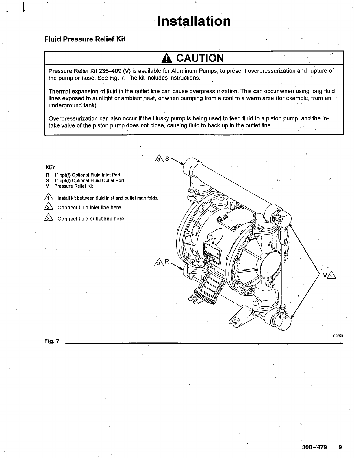
Fluid Pressure
Relief Kit
KEY
R 1" npt(f)
optional
Fluid
lnlet Port
S 1" npt(f)
Optional
Fluid
Outlet Port
V Pressure Relief
Kit
A
A
A
lnstall kit between fluid inlet and outlet manifolds.
Connect fluid inlet line here.
Connect fluid
outlet line here.
!nstallation
As
r\n
vl\
02653
Fig.7
A
CNUTION
Pressure Relief
Kit 235-409
(V)
is
available for Aluminum Pumps,
to
prevent
overpressurization and rupture
of
the
pump
or hose. See Fig.
7. The kit includes instructions.
Thermalexpansion
of
fluid in
the outlet line
can cause overpressurization.
This
can occurwhen using long fluid
lines
exposed to sunlight or ambient
heat, or when
pumping
from a
cool
to
a warm area
(for
example, from an
'
underground tank).
Overpressurization can also
occur
if
the Husky
pump
is being used
to feed fluid to
a
piston pump,
and the in-
take valve of the
piston
pump
does not close, causing fluid to back up in the outlet line.
308-1479 I
Page 10

PRESSURIZED EQUIPMENT
HAZARD
The equipment stays
pressurized
until
pressure
is
manually relieved.
To
reduce
the risk of serious
injury from
pressurized
fluid,
accidental spray from
the
gun
or splashing
fluid, follow this
procedure
whenever
you
.
.Are
instructed to relieve
pressure
.
Stop
pumping
'
o
Check,
clean
or service
any
system equipment
o
lnstall or clean fluid nozzles
W
Operation
Pressure Relief Procedure
1.
Shut off
the airto the
pump.
2.
Open
the dispensing valve,
if
used
3. Open
the fluid drain valve to relieve allfluid
pressure,
having a
container
ready to catch the
drainage.
Flush the Pump Before
First Use
The
pump
was tested in water.
lf the water
could
contaminate the
fluid
you
are
pumping,
flush the
pump
thoroughly
with a compatible solvent.
Follow the steps
under Starting.and Adjusting the Pump,
Starting and Adjusting the Pump
1. Be sure the
pump
is
properly grounded.
Refer to
Grounding on
page
4.
2.
Check
all fittings to be sure they
are tight. Be
sure
to use a compatible
liquid thread
sealant
on all
male threads. Tighten the fluid inlet
and
outlet
flttings securely.
3. Place the
suction
tube
(if
used).in the fluid to be,
pumped. ;
NOTE: lf
the
fluid inlet
pressure
to the
pump
is more
lhan
25% of the butlet
working
pressure,
the ball
check
valves will not
close
fast
enough,
resulting in inefficient
pump
operation.
4. Place the end of the fluid hose
(L)
into an
appropriate
container.
5. Close
the fluid drain valve
(J).
6.
Close the
pump
air regulator
(C).
Open all
bleed-type master air valves
(B,
E).
7. lf
the
fluid hose has a dispensing device, hold it
'
open
while
continuing
with the following
step.
8. Slowly open
the air regulator
(C)
untilthe
pump
-
starts to cycle.
Allow the
pump
to
cycle slowly
until
all air is
pushed
out of
the lines and the
pump
is
primed.
lf
you
are flushing, run the
pump
long
enough
to
thoroughly clean the
pump
and hoses. Close the
air regulator. Remove the suction tube from the
solvent and'place it in the
fluid
to be
pumped.
Pump
Shutdown
At
the end of the work shift,
relieve the
pressure
/
To reduce the risk of serious injury whenever
you
are
instructed to relieve
pressure,
always
follow
the
Pressure Relief Procedure at left.
IIIr/TENINTC
7
TOXIG FLUID HAZARD
To reduce
the risk
of serious
injury,
splashing
in the
eyes
or on the skin, and
toxic fluid spills, never move or
lift a
pump
under
pressure.
lf dropped, the
fluid
section
may rupture. Always follow the Pressure
Relief
Procedure Warning above
before lifting the
pump
tlilillir
fiil
ITAENINTC
i
10 308-479
Page 11

Maintenance
Lubrication
The air valve
is designed
to operate unlubricated,
however if lubrication
is
desired,
every 500 hours of
operation
(or
monthly) remove
the
hose from the
pump
air inlet and add two
drops
of
machine
oilto
the air
inlet.
A
CAUTION
.:
Do not
over-lubricate the
pump.
Oil
is
exhausted
through the muffler,
which
could contaminate
your
fluid
supply or other
equipment. Excessive lubrica-
tion
can
also
cause the
pump
to.malfunction.
Flushing
and
Storage
Flush the
pump
often enough to
prevent
the fluid
you
are
pumping
from drying
or treezing in
the
pump
and
damaging it.
Use
a
compatible
solvent.
Always flush
the
pump
and
relieve the
pressure
before
storing
it
for any length
of time.
Tightening Threaded
Connections
I
Before each
use,
check all
hoses
for wear
or
damage
and replace as necessary. Check to be
sure
all
,
threaded connections are tight and leak-free.
At least every six
months,
check and retorque all
threaded
connections,
including manifold
and cover
screws,
plugs,
and air valve screws.
Preventive
Maintenance Schedule
Establish
a
preventive
maintenance
schedule, based
.
on
the
pump's
service
history. This is
especially
important for
prevention
of spills
or
leakage
due to
diaphragm
failure.
To reduce the risk
of serious injury
whenever
you
are instructed to relieve
pressure,
always follow the
Pressure
Relief Procedure
on
page
10.
W
308-479
:
11
Page 12

Troubleshooting
o
Relieve the
pressure
before checking or servicing
the
equipment.
.
Check all
possible problems
and causes before
disassembling
the
pump.
To reduce the risk of serious
injury whenever
you
are instructed
to relieve
pressure,
always follow the
Pressure Relief
Procedure on
page
10.
W
PROBLEM GAUSE SOLUTION
Pump cycles
at
stall or
fails to hold
pressure
at stall.
Worn check valve balls
(301),
seats
(201)
or o-rings
(202).
Replace.
See
page
16
Pump will
not
cycle, or cycles
once
and
stops.
Air valve is stuck oi dirty. Disassemble and clean air valve.
See
pages
14-14.
Use
filtered air
Check
valve ball
(301)
severely
worn
and wedged in
seat
(201)
or
manifold
(102
or 103).
Replace ball and seat.
See
page
16.
l.t
Check valve ball
(301)
is
wedged
into
seat
(201),
due to
overpressur-
ization.
I nstall Pressure Relief
Valve
(see page
9).
Dispensing valve
clogged.
Relieve
pressure
and clear valve.
Pump
operates erratically.
Clogged suction line
lnspect;
clear
Sticky or
leaking balls
(301)
Clean or
replace.
See
page
16
Diaphragm ruptured
Replace.
See
pages
17-19
Restricted exhaust.
Remove restriction.
Air bubbles
in fluid;
Suction
line is loose Tightenr
Diaphragm ruptured. Replace. See
pages
17-19.
Loose inlet
manifold
(102),
dam-
aged seal between
manifold and
seat
(201),
damaged o-rings
(202)
Tighten manifold bolts
(106)
or
re-
place
seats
(201)
or o-rings
(202).
See
page
16.
Loose
diaphragm
shaft
bolt
(107)
Tighten
or
replace
(pages
17-19)
Damaged o-ring
(108)
Replace. See
pages
17-19
12
308-479
Page 13

Troubleshooting
PROBLEM
CAUSE
SOLUTION
Fluid in
exhaust air.
Diaphragm ruptured.
Replace.
See
pages
17-19
I
Loose diaphragm shafi bolt
(107)
Tighten
or replace
(pages
17-19).
Damaged o-ring
('108).
Replace.
See
pages
17-19.
Pump exhausts
excessive air at
stall.
Worn air valve block
(7),
o-ring
(6),
plate
(8),
pilot
block
(18),
u-cups
(10),
or
pilot pin
o-rings
(17).
Repair
or
replace.
See
pages
't+-14.
ri
Worn shaft seals
(402)
Replace.
See
pages
17-19
Pump leaks
air extemally.
Air valve cover
(2)
or air
valve
cover
screws
(3)
are
loose.
Tighten
screws. See
page
14
Air valve
gasket
(4)
or air cover
gasket
(22)
is damaged.
lnspect;
replace. See
pages
14-14,
20-21
i
Air cover screws
(25)
are loose. Tighten
screws. See
pages
20-21:
Pump leaks fluid
extemally
from
ball
check valves.
Loose manifolds
(102,
103),
dam-
aged seal
between manifold and
seat
(201),
damaged o-rings
(202).
Tighten manifold
bolts
(106)
or
re-
,
place
seats
(201)
or o-rings
(202).
See
page
16.
308-'479 :
r
13
Page 14

Sewice
Repairing
the
Air Valve
Toots Required
o
Torque wrench
o
Tox screwdriver or 8
mm
(5/16')
socket wrench
o
Needle-nose
pliers
-
o
O-ring
pick
o
Lithium base
grease
NOTE: Air Valve Repair Krt236-273
is
available.
Referto
page
23. Parts included in the kit are marked
with a symbol,
for
example
(3f).
Use
all the
parts
in
the kit for the best results.
Disassembly
1.
.,
Relieve the
pressure.
2. With a tox
screwdriver or
8 mm
(5/16")
socket
wrench, remove the six screws
(3),
air
valve
cover
(2),
and
gasket
(4).
See Fig. 8.
3. Move the valve caniage
(5)
to the
center
position
and
pull
it out of the cavity. Remove the valve
'
block
(7)
and
o-ring
(6)
from the
carriage.
Using a
needle-nose
pliers, pullthe pilot
block
(18)
straight
up and out of the cavity. See
Fig.
9.
4. Pull the two actuator
pistons
(11)
out of the
bearings
(12).
Remove the u-cup
packings
(10)
.
from the
pistons.
Pullthe'pilot
pins
(16)
out of the
bearings
(15).
Remove the
o-rings
(17)
from the
push pins.
See
Fig. 10.
5. lnspect the valve
plate
(8)
in
place.
lf damaged,
use a tox screwdriver or 8
mm
(5/16")
socket
wrench'to remove the three screws
(3).
Remove
the valve
plate
(8)
and seal
(9).
See
Fig. 11.
6.
lnspectthe bearings
(12,15)
in
place.
See Fig. 10
The bearings are tapered and, if damaged,
must
be
removed from the
outside.
This requires
disassembly of the fluid section. See
page
20.
7. Clean all
parts
and inspect for wear or
damage.
Replace as needed. Reassemble as explained on
page
14.
Reassembly
1 . tf
you
replaced the bearings
(12,
15), reinstall as
explained on
page
20. Reassemble the fluid
section-
2. lnstallthe valve
plate
seal
(9f)
into
the
groove
at
the bottom
of
the valve
cavity.
The rounded
side
of
the
seal
mustface
down
into the
groove.
See
Fig. 11
3.
lnstallthe
valve
plate
(8)
in the cavity. The
plate
is
reversible, so
either
side can face up. lnstallthe
.
three
screws
(3f),
using a tox
screwdriver or 8
mm
(5/16)
socket wrench. Tighten until the
screws bottom out on the
housing.
See Fig. 11.
4. lnstallan
o-ring
(17t)
on each
pilot
pin
(16).
Grease
the
pins
and
o'rings.
lnsert the
pins
into
the bearings
(15'1,
narrow end first.
See
Fig. 10.
5.
lnstalla u-cup
packing
(10t)
on each actuator
piston (11),
so
the lips
of
the
packings
face the
narrowend
of
the
pistons.
See
Fig. 10.
6. Lubricate the u-cup
packings
(10t)
and actuator
pistons
(11).
lnsert the actuator
pistons
in the
bearings
(12),
wide end first. Leave the nanow
end of
the
pistons
exposed. See
Fig.
10.
7 .
Grease
the lower face
of
the .pilot block
(18f)
and
install
so
its tabs
snap
into the
grooves
on
the
ends of the
pilot pins
(16).
See Fig.
9.
8. Grease the
o-ring
(6f)
and installit in the valve
block
(7t).
Push the block
onto
the
valve carriage
(5).
Grease
the lower face
of
the valve block.
See
Fig.9.
9. lnstallthe valve carriage
(5)
so its tabs slip into the
grooves
on
the narrow
end of
the actuator
pistons
(11).
See
Fig.
9.
10. Align
the valve
gasket
(4t)
and cover
(2)
with the
six
holes
in the center housing
(1).
Secure with six
screws
(3f),
using a tox screwdriver
or 8
mm
(5/16')
socket wrench.
Torque
to 38-43 in-lb
(4.3-4.9
N.m).
See
Fig.
8.
To reduce the risk of serious injury whenever
you
are instructed to relieve
pressure,
always follow the
Pressure Relief Procedure on
page
10.
W
"
14
308-479
Page 15

Seruice
A
Torqueto
38-43
6
in-lb
(4.3-4.9
N.m).
gra
A
A
lnsert
narrow
end'
fi rst.
Grease.
OtAA
114
4t
l\
lnstallwith
lips facing
'
-^-
narrow end
ofpiston
(11).
,/a\
lnsert
wide end first.
12
J
\
A
17t 15 1
6A
02644
m643
Fig.8
Detail
5
Fig. 10
A
A
3tA
Rounded side
must face
down.
'
Tighten
screws
'
untilthey bottom
out on the hous-
A
A
A
Ato
Atz
tng.
Atg
See Detail at right.
Grease.
Grease lower face.
N
\.O
-.@
I
1
A
A
ln
o
o
02642 02645
Fig.
9
o
n
Fig.11
308-479
r
15
Page 16

Ball Check Valve
Repair
'
Tools Required
.
Torque wrench
.
10 mm socket wrench
o
O-ring
pick
Disassembly
NOTE: A Fluid Section Repair
Kit is available. Referto
page
23
to
orddr
the conect kit for
your pump.
Parts
included in the kit are marked with an asterisk,
for
example'(201*). Use
allthe
parts
in the kit forthe
best
results.
,
NOTE: To ensure
proper
seating of
the balls
(301),
always replace the seats
(201)
when replacing the
balls.
Also,
on some
models, replace the o-rings
(202).
1. Relieve the
pressure.
Disconnect all
hoses.
2. Remove the
pump
from its mounting
3. Using a
10 mm
socket
wrench, remove the four
bolts
(106)
and
nuts
(114,
used
on sfain/ess
sfee/
pumps
only)
holding the outlet manifold
(103)
to
the
fluid
covers
(101).
See Fig. 12.
4. Remove the o-rings
(202,
not used
on some
models), seats
(201),
and balls
(301)
from the
manifold
(103).
5.
Turn the
pump
over and remove the
inlet manifold
'
(102).
Remove the o-rings
(202,
not used
on some
models),
seats
(201),
and balls
(301)
from the
fluid
covers
(101).
Reassembly
1. Clean
all
parts
and inspect for wear or damage.
Replace
parts
as needed.
2. Reassemble
in the reverse
order,
following all
notes in Fig. 12. Be sure the ball checks and
manifolds are assembled exactly
as.shown. The
arrows
(A)
on
the fluid Govers
(101)
must
point
toward the
outlet_manifold
(103).
:
Apply
medium-strength
(blue)
Loctite@
or
equivalent to
the threads, and torque to
120-150 in-lb
(14-17
N.m).
Arrow
(A)
must
point
toward
outlet
manifold
(103).
Beveled
seating surface
must face the ball
(301).
Not used
on some
models.
Aluminum Model Shown
Service
A
A
A
A
Ar
Al\
103
301"
201-A
202*a
101
301
*
201-l\
202*a
102
Fig.12
7
To reduce the risk of serious injury whenever
you
are instructed to relieve
pressure,
always
follow the
Pressure Relief Procedure
on
page
10.
IVtrrTENINTd
i
16 308-479
106l\
026474
Page 17

Seruice
Diaphragm
Repair
Tools Required
.
Torque
wrench
o
10 mm
socket wrench
o
15 mm
socket wrench
(aluminum
models)
or
1'
socket wrench
(stainless
steel models)
o
19 mm
socket wrench
o
O-ring
pick
o
Lithium-base
grease
Disassembly
NOTE: A Fluid
Section Repair Kit is
available. Refer to
page
23 to order the
conect kit for
your
pump.
Parts
included
in the kit are marked
with an asterisk, for
example
(401).
Use allthe
parts
in the kit forthe best
results.
1. Relieve the
pressure
2. Remove the manifolds and
disassemble the ball
checkvalves ad explained
on
page
16.
3. Using a 10 mm socket wrench, remove
the screws
(106)
holding the fluid
covers
(101)
to the air
covers
(23).
Pullthe
fluid Govers
(101)
off
the
pump.See
Fig. 13.
A
Apply
medium-strength
(blue)
Loctite@ or
equivalent
to
the threads, and torque to
121150 in;lb
(14717
N.m).
A
Arrow
(A)
must
pointtoward
airvalve
(B).
B
23
@r*
1
o1
A
A
106
A
0263s
To reduce the risk
of serious
injury
whenever
you
are instructed to relieve
pressure,
always follow the
Pressure Relief Procedure on
page
10.
W
Fig.
13
308-479'
;
17
Page 18

Service
4. Loosen but
do not remove the diaphragm shaft
bolts
(107),
using a 15
mm
socketwrench'(1"
on
stainless steel
models)
on
both bolts.
5. Unscrew one
bolt from the diaphragm shaft
(24)
and remove the o-ring
(108),
fluid
side
diaphragm
plate (105),
Teflono diaphragm
(403,
used on
Teflon@ models only), diaphragm
(401),
and air
,
side diaphragm
plate (104).
See Fig. 14.
6.
Pull the
other
diaphragm assembly and
the
diaphragm shafi
(24)
out of
the
center
housing
(1).
Hold the
shaft
flats with a 19 mm socket wrench,
and rembve the bolt
(107)
from
the
shaft.
Disassemble the remaining diaphragm
assembly.
7. lnspect the diaphragm shaft
(24)
for wear or
,
scratches.
lf it is damaged, inspect the bearings
(19)
in
place.
lf the bearings are damaged,
referto
page
20.
8. Reach into the center
housing
(1)
with an
o-ring
pick
and hook
the u-cup
packings (402),
then
pull
them
out of
the housing. This can be done with the
bearings
(19)
in
place.
9. Clean
all
parts
and inspect for wear or damage.
Replace
parts
as needed.
Reassembly
1. lnstall the
shaft
u-cup
packings
(402*)
so the
lips
face
outof
the housing
(1).
Lubricate the
packings.
See
Fig. 14.
2.
lnstall the diaphragm assembly on one end of the
shaft
(24)
as follows:
a lnstall the o-ring.(108") on the shaft bolt
(107).
b. lnstall the fluid side diaphragm
plate (105)
on
the
bolt
so
the rounded
side
faces the
diaphragm
(401).
NOTE:
On sfain/ess steel
pumps
only,lhe
fluid side
diaphragm
plate (105)
is stainless steel. This
plate
is
nof stamped with its
part
number. Be sure
to install
this
plate
on
the fluid
side of the
diaphragm,
c. On
Teflono models
only
installthe Teflono
diaphragm
(403-).
Make certain the side
marked AIR SIDE faces the center
housing
(1).
d.
lnstallthe
diaphragm
(401)
on
the bolt. Make
certain the side marked AIR SIDE faces the
center housing
(1).
e. lnstall the air side diaphragm
plate
(104)
so
the rounded side faces the diaphragm
(401).
This
plate
is used on allmodels, and is
'
stamped with
its
part
number.
f.
Apply medium-strength
(blue)
Loctite@ or
equivalent
to the
bolt
(107)
threads.
Screw
the
bolt into the
shaft
(24)
hand tight.
3. Grease the length and ends of the diaphragm shaft
(24),
and slide it through the housing
(1).
4. Assemble
the other diaphragm
assembly
to the
shaft as explained in step 2.
5.
Hold
one shaft
bolt
(107)
with a wrench and torque
the other bolt to 20-25 ft-lb
(27-34
N.m) at 100
rpm maximum.
6.
Align the fluid
covers
(101)
and the
center
housing
.
(1)
so the arows
(A).on
the
covers
faie the same
direction as the air valve
(B).
Apply
medium-strength
(blue)
Loctite@ or equivalent
to
the
threads of the screws
(106).
Secure the
covers
with the
screws
handtight.
See
Fig. 13.
Using
a 10 mm
socket wrench,
torque
the screws
oppositely and
evenly
to 120-150 in-lb
(14-17
N.m).
7. Reassemble the ball check valves and manifolds
as explained on
page
16.
18 308-479
Page 19

Service
ros
I
rozlN
403"
/\
19
'+oz{
1
'24
104 401*
AAA
Cutaway Vtew, with Diaphragms
in Place
1
02638
a2637
24a\
Cutaway
View,
with Diaph ragms Removed
ro+A
+or.A
+os-,/N,/4.
ros
I
rozA
Lips face
out of
housing
(1
).
Rounded
side faces diaphragm
(401).
Air Side must hce
center
housing
(1).
Grease.
Apply medium-strength'(blue)
Loctite@
or
equivalent. Torque to2V25 ft-lb
(27-3a
N-m)
at
100
rpm maximum.
Used on
pumps
with Teflon@ diaphragms
only.
02636
08*
1
I
244
A
A
A
A
A'
'
Fig. 14
A
'308-479'
i
19
Page 20

Seruice
:oi
Bearing
and Air
Gasket Removal
Tools Required
o
Torque
wrench
o
10 mm
socket
wrench
o
Bearing
puller
o
O-ring
pick
.
.
Press, or block and
mallet
Disassembly
NOTE: Do not remove undamaged
bearings.
1.
.
Relieve the
pressure.
2. Remove the
manifolds and disassemble the
ball
checkvalves
as
explained on
page
16.
3. . Remove the
fluid
covers
and diaplragm
assemblies
as
explained
on
page
17.
NOTE: lf
you
are
removing
only
the diaphragm shaft
bearing
(19),
skip step
4.
4. Disassemble the
air valve as explained on
page
14
5. Using
a 10 mm socket wrench,
remove the
screws
(25)
holding the air covers
(23)
to the
center
housing
(1).
See Fig. 15.
6.
Remove the
air
cover
gaskets
(22).
Always replace
the
gaskets
with new ones.
7. Use a bearing
pullerto
remove the diaphragm
shaft bearings
(19),
air valve bearings
(12)
or
pilot
pin
bearings
(15).
Do
not remove undamaged
bearings.
8.
lf
you
removed
the diaphragm shaft bearings
(19)
reach into the center housing
(1)
with
an
o-ring
pick
and hook the u-cup
packings
(402),
then
pull
them out ofthe
housing. lnspectthe
packings.
See
Fig. 14.
Reassembly
1. lf removed, installthe
shafi
u-cup
packings (402")
so the lips face out of the housing
(1).
2. The bearings
(12,
15, and 19) are tapered and can
only be installed one way. lnsert
the bearings into
the
center
hciUsing
(1),
tapered
end
first. Using a
press
or
a
block
and rubber mallet,
press-fit
the
beariig so it is flush with the surface of the center
housing.
3. Reassemble the air valve as explained on
page
'14.
4. Align the new air cover
gasket (22)
so the
pilot pin
(16)
protruding
fom the
center
housing
(1)
fits
through the
proper
hole
(H)
in the
gasket.
5. Align the air cover
(23)
so the
pilot pin
(16)
fits in
the middle hole
(M)
of
the three small holes near
the center of the cover. lnstallthe screws
(25),
handtight. Apply medium-strength
(blue)
Loctite@
or equivalent to
the threads
of
the
screws
(25).
See Fig. 15. Using a
10 mm
socket wrench,
torque
the
screws oppositely and evenly
to 130-150 in-lb
(1s-17
N.m).
6.
lnstallthe diaphragm assemblies and fluid
covers
as
explained on
page
17.
7. Reassemble the ball
check
valves and manifolds
as explained on
page
16.
To
reduce
the
risk
of serious
injury whenever
you
are instructed to relieve
pressure,
always follow the
Pressur6
Relief Procedure on
page
10.
W
20
308-479
't
Page 21

Service
A
A
A
Fig. 15
lnsert
bearings
tapered
end first.
Press-fit bearings flush with suriace of
center
housing
(1
).
Apply medium-strength
(blue)
Loctite@ or equivalent.
Torque to 13G.150 in-lb
(15-17
N.m).
12/\/\
/fir
Detail of
AirValve
Bearings
2sa
o
o
H22
1s
a/^
M
m540
1
16
19
23
0ztri9A
2
1
308-479
Page 22

Pump Matrix
Husky 1O4O Aluminum and
Stainless Steel
Pumps,
Series
A
Your Model No. is marked
on
the
pump's
serial
plate.
To determine the Model No. of
your pump
ftom the following
matrix, select the six digits which describe
your pump,
working
from
lefl
to right. The first digit is always D,
designating
Husky
diaphragm
pumps.
The remaining five digits define the materials
of construction.
For
example,
a
pump
with
an
aluminum
air motor, aluminum fluid section,
polypropylene
seats,
Teflono balls, and Teflono
diaphragms is Mbdel D7
3
-
I
1 1. To
orderreplacement
parts,
refertothe'part lists
on
pages
24-25.The digits
in the matrix
do
not
conespond
to the ref.'nos. in the
parts
drawing and isfs.
Diaphragm
Pump Air Motor Fluid
Section Seats
Balls
Diaphragms
D
(for
all
pumps)
7
(aluminum)
1
(Teflono1
1
(Teflono1
2
(acetal)
2
(acetal)
3
(aluminum)
3
(316
sst) 3
(316
sst)
4
(stainless
steel) 4
(174
PH sst) 4
(440C
sst)
5
(Hytrelo)
5
(Hytrelo)
6
(Santopreneo)
6
(Santopreneo)
6
(Santopreneo)
7
(buna-N)
7
(buna-N)
8
(Vitono)
8
(Vitono)
8
(Vitonol
9
(polypropylene)
A
(Kynaro)
:22
308-479
Page 23

Repa,ir Kit Matrix
For
Husky 1O4O Aluminum and Stainlegs Steel Pumps,
Series
A
Repair Kits may be
ordered separately. To repair the
air valve,
order
Part No. 236-273
(see page
25). Parts
included in the Air Valve Repair Kit
are
marked
with a symbol
in the
parts
list, for
example
(3f).
.
To repair
your pump,
select the six digits
which
desciibe
your pump
from the following matrix, working from left to
right. The first
digit
is
always D, the second digit is always 0
(zero),
and the third is always 7. The remaining three
digits define the
materials
of construction. Parts included in the kit are marked with an asterisk in the
parts
list, for
example
(201).
For
example, if
your pump
has
polypropylene
seats,
Teflono
balls, and
Teflono
diaphragms, order
Repair Kit D
0
7
-
I 1 1.
f
you
only need to repair certain
parts
(for
example, the diaphragms), use the 0
(null)
digits for the seats and balls, and order Repair Kit D
0
7
-
O O 1. The digits in the matrix do not
corespond
to
the ref. nos. in the
parts
drawing
and /isfs on
pages
24-25.
Diaphragm
Pump Null
Shaft O-ring Seats
Balls
Diaphragms
D
(for
all
pumps)
0
(for
all
pumps)
7
(Teflono)
0
(null)
0
(null)
0
(null)i
1
(Teflonol
1
(Teflono1
2
(acetal)
2
(acetal)
3
(316
sst) 3
(316
sst)
4
(174
PH
sst)
4
(440C
sst)
5
(HYtrelo)
5
(HYtrelo)
6
(Santopreneo)
6
(Santopreneo)
6
(Santopreneo)
7
(buna-N)
7
(buna-N)
'
8
(Vitono)
8
(Vitonol
8
(Vitono)
9
(polypropylene)
A
(Kynaro)
308-479
.
t
23
Page 24

,,
Parts
Air Motor Parts List
(Matrix
Column
2) FIuid Section
Parts List
(Matrix
Column 3)
Digit
Ref
No. Part No. Description
Qty
7 1 1
88-838
HOUSlNG,,centeq alum.
1
2 1 88-854
COVER,
airvalve; alum.
1
3t
114-023
SCREW
M5 x 0.8;
12 mm
(0.47
in.)
I
4t 188{18
GASKET, cove6
.foam
1
5 1 88-855 CARRIAGE; aluminum
1
6t
1 08-730 O-RING;nitrile
1
188{16 BLOCK, air valve; acetal
1
8
188€15 PLATE, air valve; sst
1
et 188417 SEAL, valve
plate;:buna-
N
1
10t 112-181 PACKING, u-cup; nitrile 2
11 188412 PISTON, actuatoq acetal 2
12
188{13 BEARING,
piston;
acetal
2
15
188{11
BEARING,
pin;acetal
2
16 188-610 PlN,
pilot;
stainless steel 2
171 157428
O-RING;buna-N
2
18t 188{14 BLOCK,
pilol
acetal
1
19 188-609 BEARING,
shaft;acetal 2
20 104429 STUD,
grounding
1
21
104-582 WASHER, tab 1
22
1
88-603 GASKET, air cove6
foam 2
23
188-€39
COVER,
air;
aluminum
2
24 188{08 SHAFT, diaphragm;sst 1
25
112-178
SCREW;M8x
1.25;
25
mm
(1
in.)
12
Digit
Ref.
No. Part No. Description
Qty
3
101 1 88-840
COVER, fluid;aluminum
2
102 1 88-841 MANIFOLD, inlet;
aluminum
1
103 188442 MANIFOLD,
outlet;
aluminum
1
104 188{07 PLATE,
air side;
aluminum
2
105 188{07 PI-ATE, fluid side;
aluminum
2
106 112-178 SCREW M8 x 1.25;
25 mm
(1
in.)
2+
107 112-094
BOLT;
M12 x1.75;
35
mm
(1.38
in.);
sst
2
1 08* 1 04-31 I
O-RING;Teflon@
2
110
A
1 88-970 LABEL, warning 1
111
1'.t2-182 MUFFLER 1
113 112-183 PLUG: 1'npt;cst
2
4
101 1 88-860
COVER, fluid; sst
2
102 1
88-862
MANIFOLD, inlet;sst
,|
103 1 88-861
MANIFOLD, outlet;
sst
1
104 188{07 PLATE, air
side;
aluminum
2
105 1
88-960
PLATE, fluid
side; sst
106 112-178
SCREW
M8 x 1.25;
25 mm
(1
in.)
24
107 189444
BOLT;
M12 x1.75;
35
mm
(1.38
in.);
sst
2
1
08*
1
04-31 9
O-RING;Teflon@
2
110
A
188421 LABEL,
warning 1
111
::1,i13:'r::::
114
112-182
-
:[l[6.6:,':,i:,i;:i
'.:.:
i i;
l;::.:.:.1:.::;'::,
112-257
MUFFLER
-
r
iNbt:
U sddt,!r,,,r.:ir:i;.iiii
i:ii.;riii:rirri:i,i:r:i:i:,;.i:i:i':
NUT, hex; M8 x 1.25;
sst
1
:0:.r.:ir:.r.:.:.:
. ! 4..1).rl
l
8
."
24 308-479
('
Page 25

t17
#>
11 10t
t3
H
L
15
*402
19
9<-3t
2
4t
,
Parts
'11
22
5
ot
7I
I
et
16
17t 12
A
rrs
10t
a110
04
401"
+osfi
061
23
'.t
i.
n
25
21
r
20
24
105
1
08*
{
@r
d
103
301
*
20'l*
zoz"/X
c
106
1
1
111
Aluminum Model Shown
Used on
pumps
with Teflon@
diaphragms only.
Not used on stainless
steel
pumps.
Not used
on
aluminum
pumps.
Not used on all models.
107
A
A
A
A
114
A
A
101
113
*
These
pafts
are included in the Pump Repair Kit,
which may be
purchased
separately.
Refer to the Repair Kt Matix
on
page
23 to
determine the conect kit for
your pump.
t
lhese
parts
are included in
Air Valve Repair Kt 236:273,
which
may
be
purchased
separately.
I
Replacement
Danger"and',Warning I abels,
tags and cards'are'available
at
no
cost.
*301
*201
\@
q
202*a
102
026338
106
308-479
25
Page 26

Digit
Ref,
No. Part No.
Description
atv
3 201* 188-707 SEAT; 316 stainless steel
A
202* 1
04-804 O-RING;Teflon@
4
2 201* 188{04 SEAT; acetal
4
202"
109205
O-RING;Teflon@
I
4
201!
1
88-708 SEAT; 17-4 stainle5s steel
4
202*
1 04-804
O-RING;Teflon@
4
5
201*
a-T:i:If
:2.,rQ;:?ti1,l
188-711
:i:i:i:i:i:i:!:!
"
Nb nEi
.::::i:::::
:::'
SEAT;Hytrel
4
'.0
jriir:::i:::'
o
201*
190-212
SEAT; Santoprene
4
202* 1
09-205
o-RING;Tiflono
8
I 201" 188:712
SEAT;Viton
4
,ltll,]r:;;.,.;,,i
.r
'O:,i...i.,.:.i':i
I 201* 189-722 SEAT;
polypropylene
4
202* 1
09-205
O-RING;Teflon@
8
201* 189:723
S,EAT;
Kynar 4
202" 1 09-205
O-RING;Teflon@
I
Parts
Seat
Parts List
(Matrix
Column 4)
Ball Parts List
(Matrix
Column 5)
Diaphragm
Parts List
(Matrix
Golumn 6)
Digit
Ref.
No. Part No. Description
atv
1
t
40't*
188{06 DIAPHRAGM, backup;
Hytrel
2
402* 112-181 PACKING, u-cup; nitrile 2
403* 188-605
.DIAPHRAGM;
Teflon@
2
5
401*
188{06 DIAPHRAGM; Hytrel 2
402* 112-181 PACKING,
u-cup; nitrile
2
6 401" 188-857 DIAPHRAGM; Santo-
prene
2
402* 112-181 PACKING,
u-cup;
nitrile 2
7 401" 1
88-859 DIAPHRAGM; buna-N 2
A02*
112-181 PACKING, u-cup; nitrile 2
8 401* 1 88-858 DIAPHRAGM;Viton 2
402* 112-181 PACKING, u-cup; nitrile 2
Digit
Ref.
No.
Part No.
Description
aty
1
301*
112-088
BALL;
Teflono
4
2 301" 112-254
BALL; acetal
4
3
301* 1 03-869 BALL; 316 stainless steel 4
4
301* 102-973
BALL;440C stainless
steel
4
6 301* 112-092 BALL;Santoprene 4
7
30'1* 112-O90
BALL; buna-N
4
I 301
*
112-184
BALL;Viton 4
26 308-479
Page 27

Notes
308-479
27
Page 28

112
€)
np(r)
lnlet
Dimensional Drawings
in.
mm)
6.0
52
(1
FRONTVIEW
12.0 in.
(30s
mm)
5.5 in.
('139.5
mm)
Outlet
5.0 in.
('127
mm)
1
tn. tn.
(31
2 mm)
(355.5
mm)
tn.
(337
.5 mm)
PUMP MOUNTING
HOLE PATTERN
(1
5.5
in.
(139.5
mm)
A
on
aluminum
pumps
only.
WALL BRACKET
MOUNTING HOLE PATTERN
(Viewed
from Wall)
tn.
(136.7
mm)
6.24in.
(158.5
mm)
02681
-@
I
I
-9
T-
5.0 in.
27 mm)
l_
A
1 npt(f)
"
Optional
Fluid Outlet
9.1
(231.1
mm)
314
l*
1 npt(f)
Optional
Fluid lnlet
Air
(muffler
included)
1.0 in.
(25.5
mm)
74374
125 in.
(3
mm)
3.95
in.
(100
mm)
1 npt(f)
Fluid
SIDE VIEW
Four
0.437
in.
(11.1
mm)
diameter holes
t
.'iirr.,l*n
1 npt(f)
Fluid lnlet
9.25
in.
(235
mm)
-r
1{l(
oo
r
28 308-479
Page 29

Jr,
Example of Finding Pump Air Consumption and
Air Pressure at a
Specific
Fluid Delivery and Discharge Head:
To supply 20
gpm (76
liters) fluid flow
(horizontal
scale) at
40
psi
(0.28
MPa, 2.8
bar)
discharge head
pressure
(vertical
scale)
re-
quires
approximately 20
scfm
(0.56
ms/min) air
consumption
at 70
psi
(0.49
MPa, 4.9
bar)
inlet
air
pressure.
- i
feet
psi
(MPa,
bar)
120
(0.84,8.4)
(0.84
MPa, 8.4 bar)
(0.12t-0.84
MPa,
1.4-8.4 bar)
MaximumAirConsumption ......'.:. ..... 60scfm
Air
Consumption at 70
psi/20 gpm
. . . . . 20 scfm
(see
chart)
Maximum
Free Flow Delivery . . , 42
gpm
(159
l/min)
Gallons
(Liters) per
cycle 0.15
(0.57)
Maximum
Suction
Lift . . . . .
18
ft
(5.48
m) wet
or
dry
Maximum
Size
Pumpable
Solids
. . . . 118 in.
(3.2
mm)
*
Maximum Noise Levelat 100
psi,
fullflow:
.. ....
89
dBa
'
Souhd
PowerLevel: . .. 100 dBa
*
NoiseLevelatT0psi, 50cycles/min: ........... 78dBa
Maximum
Operating Temperature 150'F
(65.5"C);
200'F
(93.3'C)
for models with Teflon@ diaphragms
Air
lnlet Size
.
.
l2npl(f)
(85.3)
240
(73.2)
100
(0.7,
7.0)
80
(0.s6,
s.6)
160
(48.8)
120
(36.6)
60
(o.42,4.2)
Technical
Data
15 20 25
(s7)
.c/6)
(es)
FLUID FLoW GPM
(lpm)
FluidlnletSize. . ...r...
1:npt(l)
FluidOutletSize.. :......
Jlnpt(f)
Wetted Parts........
Vary by Model. Referto
pages24-25.
Non-wetted ExternalParts . . Aluminum;
302 Stainless
Steel,
.
,.,,'
Polyester
(labels)
Weight
. . . . Aluminum Pumps:18 lb
(8.2
kg)
Teflono, Viton@, and
Hytrelo
are registered trademarks of
the
DuPont
Co. ,,
Santoprene@ is a registered
trademark of the Monsanlo
C9.
Kynaro is a registered trademark
of
Atochem North America,
lnc.
.l
Loctiteo is a registered
trademark of the Loctite Corporation.
.
"
Noise levels measured with the
pump
mounted on the
floor,
using
Rubber Foot Kit 236452.
Sound
power
measured
per
ISO Standard 9614-1.
:
200
0)
(61
o
UJ
t
UJ
c,
E
t
o
I
o
o.
E
D
o.
80
(24.4)
.40
(0.28,2.8)
A.
IN
A
B
C
D
AIR RESS
ES
120
psi
air
(0.84
MPa, 8.4 bar)
100
psi
air
(0.7
MPa, 7 bar)
70
psi
air
(0.49
MPa, 4.9 bar)
40
psi
air
(0.28
MPa, 2.8 bar)
AIR
E 10
scftn
(0.28
(0.56
ms/min
ms/min
)
)
F
G
H
20 scfm
30 scfrn
(0.84
ms/min),
40
scfm
(
1 2 ms/min
)
'"'B.r..
'"t
C
q.,
\
"ffi
D;
\"
,
R:{"1
\1, \x,,,.
\
\
ii;a,,,',,'r,,
\....
20
(o.14,',t.4)
5
(1e)
10
(38)
TESTCONDTTIONS
Pump tested in water with Teflon@ diaphragm and
inlet submerged.
40
(12.21
0
0
0
30 35
(114) , (132)40(1s1)
45
(170)
KEY
r::*i:::i:$:iJ::r:::
FLUTD PRESSURE AND FLOW
-
scFM
AtR
CONSUMPTTON
E.,.
r li..-r
308-479 29
Page 30

Manual Change
Suffilnor1l
This manual went from Rev. A to Rev.
G
to include the following changes:
o
PCNs A tniougn E are incorporated
in this
revision.
,i
a
.
o.
The air valve
cover screws
(Ref.
No.
3)
in the Air Motor Parts
List,
Pari trlo.'112-179,
are
changed
to 114-023.
o
A
reference
is made
to aluminum Husky
'1040
Pump Model No. 239-823, with
straight-thread manifolds. See
page
4.
o
Additionalinfcirmation
is
added
to the Dimensiona! Drawings.
'
"
"
30 308-479
Page 31

t.
i a
,Notes
xl-l .{
'i.i!:'
i'i
,-.:.
i{
ti.
,16
t
t
t
t.
4
308-479 31
+t{
,j
Page 32

'j'.i}:t'"(i]{
.
".'.
i
'"
.
(
,
.
.
r'
't
Grac:o Warranty
;,
ri''J
,
l.
.
r,
Graco
wairranis
all equipment
listed in this
manual which is manufactured by Graco and bearing
its name to be fre'Jfrom defects
in
material and workmanship on the date of sale by
an authorized;Gracq distributorto
the
original
purchaser
for
use.
Wth the exception bf
.
.
any spdcial extended or
limited warranty
published
by Graco, Graco will,
for
a
period
of twblve
months from the date
of
sale, repair or
I
replace
any
part
of the'equipment determined
by Graco to be defective.
This wananty applies only when the equipment
is installed,
-
operated
and rhaintained
in
accordance
witl Graco's written
recommendations.
-
i
This wanant! does
not
iover, ,and Graco shall
not be
liable for
general
wear and tear, or any malfunclion,
{amage
or wear cau.sed
by
.
faulty
installation,.mis'application, abrasioh, corrosion,
inadequate or improper
maintenance, negligence, accidentl,tiiirpering, oi
substitution
of non€raco component
parts.;.
Nor shall Graco
be liable for rnalfunction, darnage or wear,czlused by theiiricompatibility
of
.
.
Graco
equipment with structures, accessorids,
equipment or
materials not supplied by Graco, or the improper deiigri;
manufacture,
1
'
installation, operation'or maintenance or
structures,
accessories, equipment or
materials not
supplied
by
Graco.
j.j,..
.,
'.
This warranty is conditioned
upon the
prepaid
return
of
the
equipment
claimed to be defective to an authorized Grairj distributor
for
i.
,,,
verification of the claimed defec!.
lf the claimed defect
is verified, Graco will repair or replace free of charge any defective
parts.
The
.'
'r
equipment
will be retumed to the original
purchaser
transportation
prepaid.
lf inspection
of
the
equipment
does not disclose any
defect
Foreign Offices:
Belgium, Canada, En d, Korea, F
GRACO !NC,r
P.O.,BOX 14/.1
'
MINNEAPOLIS,
.e
,"
'l''
t'
,i;.{h
NTED
lN
U.S.A. 308-479
November 1994, Revised June
 Loading...