


Instructions–Parts List
herkules 338 Air–Operated
Diaphragm Pump
100 psi (0.7 MPa, 7 bar) Maximum Fluid Working Pressure
100 psi (0.7 MPa, 7 bar) Maximum Air Input Pressure
Model No. 234192 Acetal Pump, Series B
Important Safety Instructions
Read all warnings and instructions in this
manual. Save these instructions.
309668H
EN
herkules Equipment Corporation
2760 Ridgeway Court
Walled Lake MI 48390
01428B
Table of Contents
Warnings 2. . . . . . . . . . . . . . . . . . . . . . . . . . . . . . . . . . . . . .
Installation 4. . . . . . . . . . . . . . . . . . . . . . . . . . . . . . . . . . . . .
Operation 9. . . . . . . . . . . . . . . . . . . . . . . . . . . . . . . . . . . . .
Troubleshooting 10. . . . . . . . . . . . . . . . . . . . . . . . . . . . . . .
Maintenance 12. . . . . . . . . . . . . . . . . . . . . . . . . . . . . . . . . .
Service
Replacing the Air Valve 13. . . . . . . . . . . . . . . . . . . . . .
Repairing the Air Valve 15. . . . . . . . . . . . . . . . . . . . . .
Ball Check Valves 18. . . . . . . . . . . . . . . . . . . . . . . . . .
Diaphragm Repair 20. . . . . . . . . . . . . . . . . . . . . . . . . .
Parts 23. . . . . . . . . . . . . . . . . . . . . . . . . . . . . . . . . . . . . . . .
Torque Sequence 26. . . . . . . . . . . . . . . . . . . . . . . . . . . . .
Technical Data and Performance Charts 27. . . . . . . . . .
Dimensions 28. . . . . . . . . . . . . . . . . . . . . . . . . . . . . . . . . . .
herkules Information 30. . . . . . . . . . . . . . . . . . . . . . . . . . .
Symbols
Warning Symbol
WARNING
This symbol alerts you to the possibility of serious
injury or death if you do not follow the instructions.
Caution Symbol
CAUTION
This symbol alerts you to the possibility of damage to
or destruction of equipment if you do not follow the
instructions.
INSTRUCTIONS
WARNING
WARNING
EQUIPMENT MISUSE HAZARD
Equipment misuse can cause the equipment to rupture or malfunction and result in serious injury.
D This equipment is for professional use only.
D Read all instruction manuals, tags, and labels before operating the equipment.
D Use the equipment only for its intended purpose. If you are not sure, call your herkules distributor.
D Do not alter or modify this equipment. Use only genuine herkules parts and accessories.
D Check equipment daily. Repair or replace worn or damaged parts immediately.
D Do not exceed the maximum working pressure of the lowest rated component in your system.
This equipment has a 100 psi (0.7 MPa, 7 bar) maximum working pressure at 100 psi
(0.7 MPa, 7 bar) maximum incoming air pressure.
D Use fluids and solvents which are compatible with the equipment wetted parts. Refer to the
Technical Data section of all equipment manuals. Read the fluid and solvent manufacturer’s
warnings.
D Do not use hoses to pull equipment.
D Route hoses away from traffic areas, sharp edges, moving parts, and hot surfaces. Do not
expose herkules hoses to temperatures above 82_ C (180_ F) or below –40_ C (–40_ F).
D Do not lift pressurized equipment.
D Comply with all applicable local, state, and national fire, electrical, and safety regulations.
2 309668

WARNING
WARNING
TOXIC FLUID HAZARD
Hazardous fluid or toxic fumes can cause serious injury or death if splashed in the eyes or on the
skin, inhaled, or swallowed.
D Know the specific hazards of the fluid you are using.
D Store hazardous fluid in an approved container. Dispose of hazardous fluid according to all local,
state and national guidelines.
D Always wear protective eyewear, gloves, clothing and respirator as recommended by the fluid
and solvent manufacturer.
D Pipe and dispose of the exhaust air safely, away from people, animals, and food handling areas.
If the diaphragm fails, the fluid is exhausted along with the air. See Air Exhaust Ventilation on
page 8.
D To pump acids, always use a polypropylene pump. Take precautions to avoid acid or acid fumes
from contacting the pump housing exterior. Stainless steel parts will be damaged by exposure to
acid spills and fumes. Never use an acetal pump to pump acids.
FIRE AND EXPLOSION HAZARD
Improper grounding, poor ventilation, open flames or sparks can cause a hazardous condition and
result in a fire or explosion and serious injury.
D Ground the equipment. Refer to Grounding on page 5.
D Never use a polypropylene pump with non-conductive flammable fluids as specified by your local
fire protection code. Refer to Grounding on page 5 for additional information. Consult your fluid
supplier to determine the conductivity or resistivity of your fluid.
D If there is any static sparking or you feel an electric shock while using this equipment, stop
pumping immediately. Do not use the equipment until you identify and correct the problem.
D Provide fresh air ventilation to avoid the buildup of flammable fumes from solvents or the fluid
being pumped.
D Pipe and dispose of the exhaust air safely, away from all sources of ignition. If the diaphragm
fails, the fluid is exhausted along with the air. See Air Exhaust Ventilation on page 8.
D Keep the work area free of debris, including solvent, rags, and gasoline.
D Electrically disconnect all equipment in the work area.
D Extinguish all open flames or pilot lights in the work area.
D Do not smoke in the work area.
D Do not turn on or off any light switch in the work area while operating or if fumes are present.
D Do not operate a gasoline engine in the work area.
309668 3
Installation
General Information
D Contact your herkules distributor for assistance in
planning a system to suit your needs.
D Always use Genuine herkules Parts and Accesso-
ries, available from your herkules distributor. If you
supply your own accessories, be sure they are
adequately sized and pressure rated for your
system.
D Use a compatible, liquid thread sealant or PTFE
tape on all male threads. Tighten all connections
firmly to avoid air or fluid leaks. Do not over-
tighten plastic threads.
D Reference numbers and letters in parentheses refer
to the callouts in the Figures and the parts lists on
pages 23 to 24.
WARNING
TOXIC FLUID HAZARD
Hazardous fluid or toxic fumes can
cause serious injury or death if splashed
in the eyes or on the skin, inhaled, or
swallowed.
1. Read TOXIC FLUID HAZARD on page 3.
2. Use fluids and solvents which are compatible
with the equipment wetted parts. Refer to the
Technical Data section of all equipment manuals. Read the fluid and solvent manufacturer’s
warnings.
CAUTION
Safe Operating Temperature
Minimum: 40_F (4.4_C); Maximum: 150_F (66_C).
Operating outside these temperature limits will
adversely affect the strength of the pump housing.
Certain chemicals may further reduce the operating temperature range. Consult engineering guides
for chemical compatibilities and temperature limits,
or contact your herkules distributor.
Tightening Threaded Fasteners Before
First Use
Before using the pump for the first time, check and
retorque all external fasteners. See Torque Se-
quence, page 26. After the first day of operation,
retorque the fasteners. Although pump use varies, a
general guideline is to retorque fasteners every two
months.
Mountings
D Be sure the mounting can support the weight of the
pump, hoses, and accessories, as well as the
stress caused during operation.
D The herkules 338 Pump can be used in a variety of
installations. Kits are available to adapt your pump
to your system.
D For all other mountings, be sure the pump is ade-
quately secured.
4 309668
Installation
Grounding
WARNING
FIRE AND EXPLOSION HAZARD
This pump must be grounded. Before
operating the pump, ground the system
as explained at right. Also read the section FIRE AND EXPLOSION HAZARD
on page 3.
The acetal pump contains stainless steel fibers,
which makes the wetted parts conductive.
Attaching the ground wire to the grounding strip
grounds the air motor and the wetted parts.
When pumping conductive flammable fluids,
always ground the entire fluid system by making
sure the fluid system has an electrical path to a
true earth ground.
US Code (NFPA 77 Static Electricity) recommends
a conductivity greater than 50 x 10
ter (mhos/meter) over your operating temperature
range to reduce the hazard of fire. Consult your
fluid supplier to determine the conductivity or
resistivity of your fluid. The resistivity must be less
than 2 x 10¹² ohm-centimeters.
–12
Siemans/me-
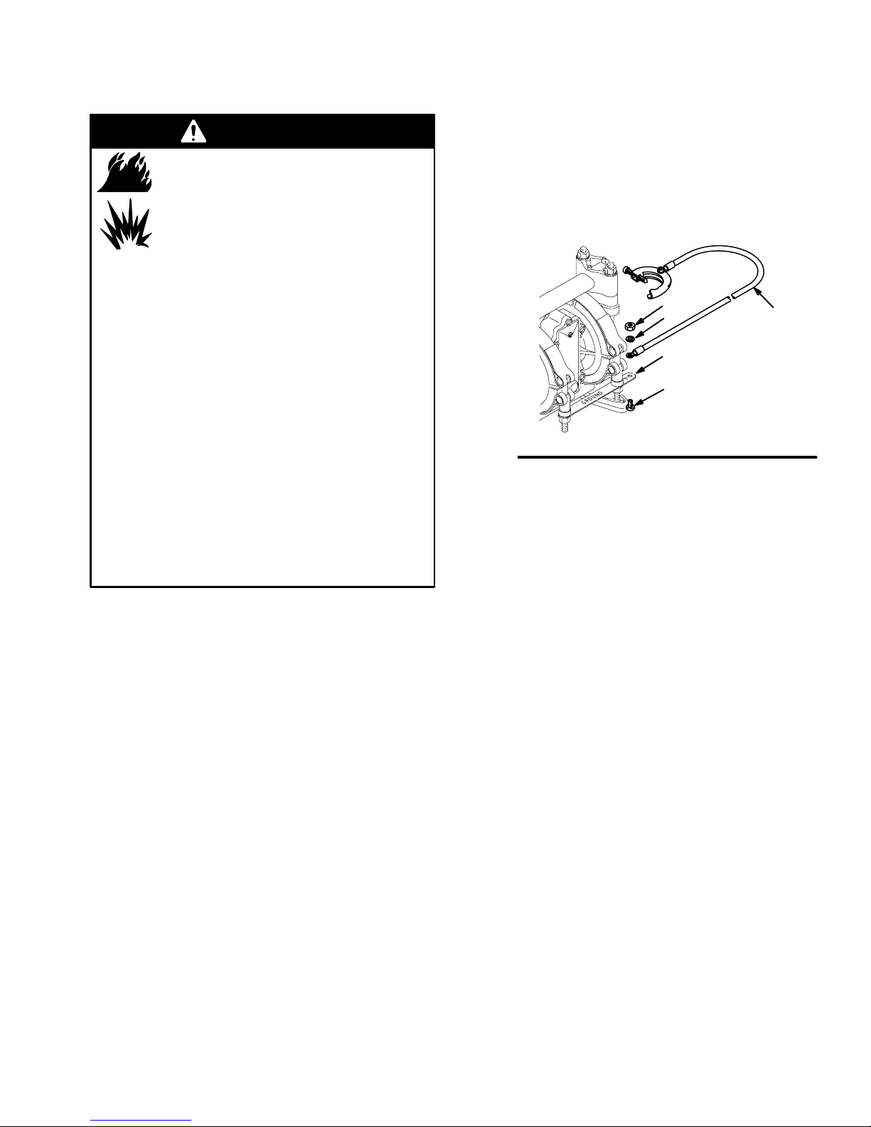
Ground all of this equipment:
D Pump: Attach a ground wire (Y) to the grounding
strip (112) with the screw (28), lockwasher (29) and
nut (27), as shown in Fig. 1. Connect the clamp end
of the ground wire to a true earth ground. Order
Part No. 222011 Ground Wire and Clamp.
27
29
112
28
Fig. 1
D Air and fluid hoses: Use only electrically conductive
hoses.
D Air compressor: Follow the manufacturer’s recom-
mendations.
Y
01432B
To reduce the risk of static sparking, ground the pump
and all other equipment used or located in the pumping
area. Check your local electrical code for detailed
grounding instructions for your area and type of equipment.
D Solvent pails used when flushing: Follow your local
code. Use only metal pails, which are conductive.
Do not place the pail on a non-conductive surface,
such as paper or cardboard, which interrupts the
grounding continuity.
D Fluid supply container: Follow your local code.
309668 5

Installation
Air Line
WARNING
A bleed-type master air valve (B) is required in
your system to relieve air trapped between this
valve and the pump. Trapped air can cause the
pump to cycle unexpectedly, which could result in
serious injury, including splashing in the eyes or on
the skin, injury from moving parts, or contamination
from hazardous fluids.
CAUTION
The pump exhaust air may contain contaminants.
Ventilate to a remote area if the contaminants
could affect your fluid supply. See Air Exhaust
Ventilation on page 8.
1. Install the air line accessories. Mount these
accessories on the wall or on a bracket. Be sure
the air line supplying the accessories is grounded.
a. The fluid pressure can be controlled in either
of two ways. To control it on the air side, install
an air regulator (H). To control it on the fluid
side, install a fluid regulator (M) near the pump
fluid outlet.
b. Locate one bleed-type master air valve (B)
close to the pump and use it to relieve trapped
air. See the WARNING above. Locate the
other master air valve (E) upstream from all air
line accessories and use it to isolate them
during cleaning and repair.
c. The air line filter (F) removes harmful dirt and
moisture from the compressed air supply.
Fluid Suction Line
D The pump fluid inlet is 3/8 npt(f). See Fig. 2.
Screw the fluid fitting into the pump inlet snugly.
Use a compatible liquid thread sealant or PTFE
tape on connections to prevent air from getting into
material line.
D At inlet fluid pressures greater than 15 psi (0.1
MPa,1 bar), diaphragm life will be shortened.
D See the Technical Data on page 27 for maximum
suction lift and flow rate loss at various lift distances.
Fluid Outlet Line
WARNING
A fluid drain valve (J) is required in your system to
relieve pressure in the hose if it is plugged. The
drain valve reduces the risk of serious injury,
including splashing in the eyes or on the skin, or
contamination from hazardous fluids when relieving
pressure. Install the valve close to the pump fluid
outlet.
D Use electrically conductive fluid hoses (N). The
pump fluid outlet is 3/8 npt(f). See Fig. 2. Screw the
fluid fitting into the pump outlet snugly.
2. Install an electrically conductive, flexible air hose
(C) between the accessories and the 1/4 npt(f)
pump air inlet. Use a minimum 1/4” (6.3 mm) ID air
hose. Screw an air line quick disconnect coupler
(D) onto the end of the air hose (C), and screw the
mating fitting into the pump air inlet snugly. Do not
connect the coupler (D) to the fitting yet.
6 309668
D Install a fluid regulator (M) at the pump fluid outlet
to control fluid pressure, if desired. See Air Line,
step 1a, for another method of controlling pressure.
D Install a fluid drain valve (J) near the fluid outlet.
See the WARNING above.

Fluid Pressure Relief Valve
CAUTION
Installation
KEY
A 3/8 npt(f) fluid inlet port
B 3/8 npt(f) fluid outlet port
C Pressure relief valve
Part No. 112119 (stainless steel)
Some systems may require installation of a pressure relief valve at the pump outlet to prevent
overpressurization and rupture of the pump or
hose. See Fig. 2.
Thermal expansion of fluid in the outlet line can
cause overpressurization. This can occur when
using long fluid lines exposed to sunlight or ambient heat, or when pumping from a cool to a warm
area (for example, from an underground tank).
Overpressurization can also occur if the herkules
pump is being used to feed fluid to a piston pump,
and the intake valve of the piston pump does not
close, causing fluid to back up in the outlet line.
1
Install valve between fluid inlet and outlet ports.
2
Connect fluid inlet line here. Use a compatible liquid thread sealant or PTFE tape on
connection to prevent air from getting into
the material line.
3
Connect fluid outlet line here.
B 1
3
1
A
2
Fig. 2
C
01539B
309668 7

Installation
Air Exhaust Ventilation
WARNING
FIRE AND EXPLOSION HAZARD
Be sure to read FIRE OR EXPLOSION
HAZARD and TOXIC FLUID HAZARD
on page 3, before operating this pump.
Be sure the system is properly ventilated
for your type of installation. You must
vent the exhaust to a safe place, away
from people, animals, food handling
areas, and all sources of ignition when
pumping flammable or hazardous fluids.
Diaphragm failure will cause the fluid being
pumped to exhaust with the air. Place an appropriate container at the end of the air exhaust line to
catch the fluid. See Fig. 3.
The air exhaust port is 3/8 npt(f). Do not restrict the air
exhaust port. Excessive exhaust restriction can cause
erratic pump operation.
To exhaust to a remote location:
1. Remove the muffler (11) from the pump air
exhaust port.
WARNING
PRESSURIZED EQUIPMENT HAZARD
To reduce the risk of serious eye injury
from ice particles, never operate the
pump with the air exhaust port open. Ice
may form during pump operation, and ice particles
will be ejected from the port along with the exhaust
air. If the muffler (11) is removed, always connect
an air exhaust hose to the exhaust port.
2. Install an electrically conductive air exhaust hose
(X) and connect the muffler to the other end of the
hose. The minimum size for the air exhaust hose
is 3/8 in. (10 mm) ID. If a hose longer than 15 ft
(4.57 m) is required, use a larger diameter hose.
Avoid sharp bends or kinks in the hose.
3. Place a container (Z) at the end of the air exhaust
line to catch fluid in case a diaphragm ruptures. If
the fluid is flammable, ground the container. See
Fig. 3.
Fig. 3
VENTING EXHAUST AIR (Submerged Installation Shown)
In a submerged installation (as shown), all wetted and non-wetted
pump parts must be compatible with the fluid being pumped.
11
X
Z
01445A
8 309668

Operation
Pressure Relief Procedure
WARNING
PRESSURIZED EQUIPMENT HAZARD
The system pressure must be manually relieved to
prevent the system from starting or spraying accidentally. To reduce the risk of an injury from accidental spray from the gun, splashing fluid, or moving parts, follow the Pressure Relief Procedure
whenever you
D Are instructed to relieve the pressure
D Stop spraying
D Check or service any of the system equipment
D Install or clean the spray tips
1. Shut off the air to the pump.
2. Open the dispensing valve, if used.
3. Open the fluid drain valve to relieve all fluid pressure, having a container ready to catch the drainage.
Flush the Pump Before First Use
The pump was tested in water. If water could contaminate the fluid you are pumping, flush it thoroughly with
a compatible solvent. Follow the steps under Starting
and Adjusting the Pump.
Starting and Adjusting the Pump
WARNING
1. Be sure the pump is properly grounded. Read
FIRE OR EXPLOSION HAZARD on page 3.
2. Check all fittings to be sure they are tight. Be sure
to use a compatible liquid thread sealant or PTFE
tape on all male threads. Tighten the fluid inlet and
outlet fittings snugly. Do not overtighten the fittings
into the pump.
3. Place the suction tube (if used) in the fluid to be
pumped.
4. Place the end of the fluid hose (N) into an
appropriate container. Close the fluid drain valve
(J).
5. With the pump air regulator (H) closed, open all
bleed-type master air valves (B, E).
6. If the fluid hose has a dispensing device, hold it
open while continuing with the following step.
Slowly open the air regulator (H) until the pump
starts to cycle. Allow the pump to cycle slowly until
all air is pushed out of the lines and the pump is
primed.
If you are flushing, run the pump long enough to
thoroughly clean the pump and hoses. Close the
air regulator. Remove the suction tube from the
solvent and place it in the fluid to be pumped.
Pump Shutdown
TOXIC FLUID HAZARD
Hazardous fluid or toxic fumes can
cause serious injury or death if splashed
in the eyes or on the skin, inhaled, or
swallowed. Do not lift a pump under pressure. If
dropped, the fluid section may rupture. Always
follow the Pressure Relief Procedure above
before lifting the pump.
WARNING
To reduce the risk of serious injury whenever you
are instructed to relieve pressure, always follow the
Pressure Relief Procedure at left.
At the end of the work shift, relieve the pressure.
309668 9
 Loading...