


 Loading...
Operation
312062W
EN
Hydraulic, Heated, Plural Component Proportioner
For spraying polyurethane foam and polyurea coatings. For professional use only.
Not approved for use in European explosive atmosphere locations.
Important Safety Instructions
Read all warnings and instructions in this manual. Save these instructions.
See page 3 for model information, including maximum working pressure and approvals.
Model H-40 Shown
T9830a
Contents
Systems . . . . . . . . . . . . . . . . . . . . . . . . . . . 3
Models . . . . . . . . . . . . . . . . . . . . . . . . . . . . 5
Supplied Manuals . . . . . . . . . . . . . . . . . . . 7
Related Manuals . . . . . . . . . . . . . . . . . . . . 8
Warnings . . . . . . . . . . . . . . . . . . . . . . . . . . 9
Important Two-Component Material
Information . . . . . . . . . . . . . . . . . . . . . 12
Isocyanate Conditions . . . . . . . . . . . . . . . . . . . . 12 Material Self-ignition . . . . . . . . . . . . . . . . . . . . . 12 Keep Components A and B Separate . . . . . . . . 12 Moisture Sensitivity of Isocyanates . . . . . . . . . . 12 Foam Resins with 245 fa Blowing Agents . . . . . 13 Changing Materials . . . . . . . . . . . . . . . . . . . . . . 13
Typical Installation, with circulation . . . 14 Typical Installation, without circulation 15 Component Identification . . . . . . . . . . . . 16 Temperature Controls and Indicators . . 18
Main Power Switch . . . . . . . . . . . . . . . . . . . . . . 18
Red Stop Button . . . . . . . . . . . . . . . . . . . . . . . . 18
Actual Temperature Key/LED . . . . . . . . . . . . . . 19
Target Temperature Key/LED . . . . . . . . . . . . . . 19
Temperature Scale Keys/LEDs . . . . . . . . . . . . . 19
Heater Zone On/Off Keys/LEDs . . . . . . . . . . . . 19
Temperature Arrow Keys . . . . . . . . . . . . . . . . . 19
Temperature Displays . . . . . . . . . . . . . . . . . . . . 19
Circuit Breakers . . . . . . . . . . . . . . . . . . . . . . . . 20
Motor Controls and Indicators . . . . . . . . 21
Motor ON/OFF Key/LED . . . . . . . . . . . . . . . . . . 21
PARK Key/LED . . . . . . . . . . . . . . . . . . . . . . . . . 21
PSI/BAR Keys/LEDs . . . . . . . . . . . . . . . . . . . . . 21
Pressure Key/LED . . . . . . . . . . . . . . . . . . . . . . 21
Cycle Count Key/LED . . . . . . . . . . . . . . . . . . . . 22
Hydraulic Pressure Control Knob . . . . . . . . . . . 22
Motor Control Arrow Keys . . . . . . . . . . . . . . . . . 22
Spray Adjustments . . . . . . . . . . . . . . . . . 22
Setup . . . . . . . . . . . . . . . . . . . . . . . . . . . . . 23
Startup . . . . . . . . . . . . . . . . . . . . . . . . . . . 30
Spraying . . . . . . . . . . . . . . . . . . . . . . . . . . 35
Standby . . . . . . . . . . . . . . . . . . . . . . . . . . . 37
Shutdown . . . . . . . . . . . . . . . . . . . . . . . . . 38
Pressure Relief Procedure . . . . . . . . . . . 39
Fluid Circulation . . . . . . . . . . . . . . . . . . . .40
Circulation Through Reactor . . . . . . . . . . . . . . . 40
Circulation Through Gun Manifold . . . . . . . . . . . 41
Diagnostic Codes . . . . . . . . . . . . . . . . . . .42
Temperature Control Diagnostic Codes . . . . . . 42
Motor Control Diagnostic Codes . . . . . . . . . . . . 43
Maintenance . . . . . . . . . . . . . . . . . . . . . . .44
Fluid Inlet Strainer Screen . . . . . . . . . . . . . . . . . 45
Pump Lubrication System . . . . . . . . . . . . . . . . . 46
Flushing . . . . . . . . . . . . . . . . . . . . . . . . . .47
Dimensions . . . . . . . . . . . . . . . . . . . . . . . .48
Technical Data . . . . . . . . . . . . . . . . . . . . .49
Performance Charts . . . . . . . . . . . . . . . . .50
Graco Standard Warranty . . . . . . . . . . . .52
Graco Information . . . . . . . . . . . . . . . . . .52
2 |
312062W |
Systems
Systems
|
Maximum Fluid |
|
Heated Hose |
Gun |
|
|
|
|
Working |
|
|
|
|
|
|
|
|
|
|
|
|
|
|
|
Pressure |
Proportioner |
|
|
|
|
Mix |
Part |
psi (MPa, bar) |
(see page 3) |
50 ft (15 m) |
10 ft (3 m) |
Model |
Part |
Chamber Kit |
|
|
|
|
|
|
|
|
AP3400 |
2000 (13.8, 138) |
253400 |
246678 |
246050 |
Fusion Air Purge |
246101 |
AR5252 |
AP3401 |
2000 (13.8, 138) |
253401 |
246678 |
246050 |
Fusion Air Purge |
246101 |
AR5252 |
AP3402 |
2000 (13.8, 138) |
253402 |
246678 |
246050 |
Fusion Air Purge |
246101 |
AR5252 |
AP3403 |
3500 (24.1, 241) |
253403 |
246679 |
246055 |
Fusion Air Purge |
246101 |
AR4242 |
AP3404 |
3500 (24.1, 241) |
253404 |
246679 |
246055 |
Fusion Air Purge |
246101 |
AR4242 |
AP3405 |
3500 (24.1, 241) |
253405 |
246679 |
246055 |
Fusion Air Purge |
246101 |
AR4242 |
AP3407 |
2000 (13.8, 138) |
253407 |
246678 |
246050 |
Fusion Air Purge |
246101 |
AR5252 |
AP3408 |
2000 (13.8, 138) |
253408 |
246678 |
246050 |
Fusion Air Purge |
246101 |
AR5252 |
AP3725 |
1700 (11.7, 117) |
253725 |
246678 |
246050 |
Fusion Air Purge |
246101 |
AR5252 |
AP3726 |
2000 (13.8, 138) |
253726 |
246678 |
246050 |
Fusion Air Purge |
246101 |
AR5252 |
AP3727 |
2000 (13.8, 138) |
253727 |
246678 |
246050 |
Fusion Air Purge |
246101 |
AR5252 |
AP5400 |
2000 (13.8, 138) |
255400 |
246678 |
246050 |
Fusion Air Purge |
246101 |
AR5252 |
AP5401 |
2000 (13.8, 138) |
255401 |
246678 |
246050 |
Fusion Air Purge |
246101 |
AR5252 |
AP5402 |
2000 (13.8, 138) |
255402 |
246678 |
246050 |
Fusion Air Purge |
246101 |
AR5252 |
AP5403 |
3500 (24.1, 241) |
255403 |
246679 |
246055 |
Fusion Air Purge |
246100 |
AR2929 |
AP5404 |
3500 (24.1, 241) |
255404 |
246679 |
246055 |
Fusion Air Purge |
246100 |
AR2929 |
AP5405 |
3500 (24.1, 241) |
255405 |
246679 |
246055 |
Fusion Air Purge |
246100 |
AR2929 |
AP5406 |
2000 (13.8, 138) |
255406 |
246678 |
246050 |
Fusion Air Purge |
246101 |
AR5252 |
AP5407 |
2000 (13.8, 138) |
255407 |
246678 |
246050 |
Fusion Air Purge |
246101 |
AR5252 |
AP5408 |
2000 (13.8, 138) |
255408 |
246678 |
246050 |
Fusion Air Purge |
246101 |
AR5252 |
AP6505 |
2000 (13.8, 138) |
256505 |
246678 |
246050 |
Fusion Air Purge |
246101 |
AR5252 |
AP6506 |
2000 (13.8, 138) |
256506 |
246678 |
246050 |
Fusion Air Purge |
246101 |
AR5252 |
CS5400 |
2000 (13.8, 138) |
255400 |
246678 |
246050 |
Fusion CS |
CS02RD |
|
CS5401 |
2000 (13.8, 138) |
255401 |
246678 |
246050 |
Fusion CS |
CS02RD |
|
CS5402 |
2000 (13.8, 138) |
255402 |
246678 |
246050 |
Fusion CS |
CS02RD |
|
CS5406 |
2000 (13.8, 138) |
255406 |
246678 |
246050 |
Fusion CS |
CS02RD |
|
CS5407 |
2000 (13.8, 138) |
255407 |
246678 |
246050 |
Fusion CS |
CS02RD |
|
CS5408 |
2000 (13.8, 138) |
255408 |
246678 |
246050 |
Fusion CS |
CS02RD |
|
CE approval does not apply.
312062W |
3 |
Systems
Systems Continued
|
Maximum Fluid |
|
Heated Hose |
Gun |
|
|
|
Working |
|
|
|
|
|
|
|
|
|
|
|
|
|
Pressure |
Proportioner |
|
|
|
|
Part |
psi (MPa, bar) |
(see page 3) |
50 ft (15 m) |
10 ft (3 m) |
Model |
Part |
|
|
|
|
|
|
|
P23400 |
2000 (13.8, 138) |
253400 |
246678 |
246050 |
Probler P2 |
GCP2R2 |
P23401 |
2000 (13.8, 138) |
253401 |
246678 |
246050 |
Probler P2 |
GCP2R2 |
P23402 |
2000 (13.8, 138) |
253402 |
246678 |
246050 |
Probler P2 |
GCP2R2 |
P23403 |
3500 (24.1, 241) |
253403 |
246679 |
246055 |
Probler P2 |
GCP2R1 |
P23404 |
3500 (24.1, 241) |
253404 |
246679 |
246055 |
Probler P2 |
GCP2R1 |
P23405 |
3500 (24.1, 241) |
253405 |
246679 |
246055 |
Probler P2 |
GCP2R1 |
P23407 |
2000 (13.8, 138) |
253407 |
246678 |
246050 |
Probler P2 |
GCP2R2 |
P23408 |
2000 (13.8, 138) |
253408 |
246678 |
246050 |
Probler P2 |
GCP2R2 |
P23725 |
1700 (11.7, 117) |
253725 |
246678 |
246050 |
Probler P2 |
GCP2R2 |
P23726 |
2000 (13.8, 138) |
253726 |
246678 |
246050 |
Probler P2 |
GCP2R2 |
P23727 |
2000 (13.8, 138) |
253727 |
246678 |
246050 |
Probler P2 |
GCP2R2 |
P25400 |
2000 (13.8, 138) |
255400 |
246678 |
246050 |
Probler P2 |
GCP2R2 |
P25401 |
2000 (13.8, 138) |
255401 |
246678 |
246050 |
Probler P2 |
GCP2R2 |
P25402 |
2000 (13.8, 138) |
255402 |
246678 |
246050 |
Probler P2 |
GCP2R2 |
P25403 |
3500 (24.1, 241) |
255403 |
246679 |
246055 |
Probler P2 |
GCP2R0 |
P25404 |
3500 (24.1, 241) |
255404 |
246679 |
246055 |
Probler P2 |
GCP2R0 |
P25405 |
3500 (24.1, 241) |
255405 |
246679 |
246055 |
Probler P2 |
GCP2R0 |
P25406 |
2000 (13.8, 138) |
255406 |
246678 |
246050 |
Probler P2 |
GCP2R2 |
P25407 |
2000 (13.8, 138) |
255407 |
246678 |
246050 |
Probler P2 |
GCP2R2 |
P25408 |
2000 (13.8, 138) |
255408 |
246678 |
246050 |
Probler P2 |
GCP2R2 |
P26505 |
2000 (13.8, 138) |
256505 |
246678 |
246050 |
Probler P2 |
GCP2R2 |
P26506 |
2000 (13.8, 138) |
256506 |
246678 |
246050 |
Probler P2 |
GCP2R2 |
CE approval does not apply.
4 |
312062W |
Models
Models
H-25 SERIES
|
|
|
|
|
Max Flow |
Approximate |
|
Maximum Fluid |
|
Full Load |
|
|
Primary |
Rate |
Output per |
Hydraulic |
Working |
|
Peak Amps* |
Voltage |
System |
Heater |
lb/min |
Cycle (A+B) |
Pressure |
Pressure |
Part, Series |
Per Phase |
(phase) |
Watts† |
Watts |
(kg/min) |
gal. (liter) |
Ratio |
psi (MPa, bar) |
|
|
|
|
|
|
|
|
|
255400, F |
69 |
230V (1) |
15,960 |
8,000 |
22 (10) |
0.063 (0.24) |
1.91:1 |
2000 (13.8, 138) |
255401, F |
46 |
230V (3) |
15,960 |
8,000 |
22 (10) |
0.063 (0.24) |
1.91:1 |
2000 (13.8, 138) |
255402, F |
35 |
400V (3) |
15,960 |
8,000 |
22 (10) |
0.063 (0.24) |
1.91:1 |
2000 (13.8, 138) |
255406, F |
100 |
230V (1) |
23,260 |
15,300 |
22 (10) |
0.063 (0.24) |
1.91:1 |
2000 (13.8, 138) |
255407, F |
59 |
230V (3) |
23,260 |
15,300 |
22 (10) |
0.063 (0.24) |
1.91:1 |
2000 (13.8, 138) |
255408, F |
35 |
400V (3) |
23,260 |
15,300 |
22 (10) |
0.063 (0.24) |
1.91:1 |
2000 (13.8, 138) |
H-40 SERIES |
|
|
|
|
|
|
|
|
|
|
|
|
|
|
|
|
|
|
|
|
|
|
Max Flow |
Approximate |
|
Maximum Fluid |
|
Full Load |
|
|
Primary |
Rate |
Output per |
Hydraulic |
Working |
|
Peak Amps* |
Voltage |
System |
Heater |
lb/min |
Cycle (A+B) |
Pressure |
Pressure |
Part, Series |
Per Phase |
(phase) |
Watts† |
Watts |
(kg/min) |
gal. (liter) |
Ratio |
psi (MPa, bar) |
|
|
|
|
|
|
|
|
|
253400, E |
100 |
230V (1) |
23,100 |
12,000 |
45 (20) |
0.063 (0.24) |
1.91:1 |
2000 (13.8, 138) |
253401, E |
71 |
230V (3) |
26,600 |
15,300 |
45 (20) |
0.063 (0.24) |
1.91:1 |
2000 (13.8, 138) |
253402, E |
41 |
400V (3) |
26,600 |
15,300 |
45 (20) |
0.063 (0.24) |
1.91:1 |
2000 (13.8, 138) |
253407, E |
95 |
230V (3) |
31,700 |
20,400 |
45 (20) |
0.063 (0.24) |
1.91:1 |
2000 (13.8, 138) |
253408, E |
52 |
400V (3) |
31,700 |
20,400 |
45 (20) |
0.063 (0.24) |
1.91:1 |
2000 (13.8, 138) |
H-50 SERIES |
|
|
|
|
|
|
|
|
|
|
|
|
|
|
|
|
|
|
|
|
|
|
Max Flow |
Approximate |
|
Maximum Fluid |
|
Full Load |
|
|
Primary |
Rate |
Output per |
Hydraulic |
Working |
|
Peak Amps* |
Voltage |
System |
Heater |
lb/min |
Cycle (A+B) |
Pressure |
Pressure |
Part, Series |
Per Phase |
(phase) |
Watts† |
Watts |
(kg/min) |
gal. (liter) |
Ratio |
psi (MPa, bar) |
|
|
|
|
|
|
|
|
|
253725, E |
100 |
230V (1) |
23,100 |
12,000 |
52 (24) |
0.073 (0.28) |
1.64:1 |
1700 (11.7, 117) |
253726, E |
71 |
230V (3) |
26,600 |
15,300 |
52 (24) |
0.073 (0.28) |
1.64:1 |
2000 (13.8, 138) |
253727, E |
41 |
400V (3) |
26,600 |
15,300 |
52 (24) |
0.073 (0.28) |
1.64:1 |
2000 (13.8, 138) |
256505, E |
95 |
230V (3) |
31,700 |
20,400 |
52 (24) |
0.073 (0.28) |
1.64:1 |
2000 (13.8, 138) |
256506, E |
52 |
400V (3) |
31,700 |
20,400 |
52 (24) |
0.073 (0.28) |
1.64:1 |
2000 (13.8, 138) |
312062W |
5 |

|
|
|
|
|
|
|
|
|
|
|
|
|
Models |
H-XP2 SERIES |
|
|
|
|
|
|
|
|
|
|
|
|
|
|
|
|
|
|
|
|
|
|
|
|
|
|
|
|
|
|
|
|
|
|
|
|
Approximate |
|
|
|
Maximum Fluid |
|
Full Load |
|
|
|
Primary |
|
Max Flow |
|
Output per |
|
Hydraulic |
|
Working |
|
Peak Amps* |
Voltage |
System |
|
Heater |
|
Rate |
|
Cycle (A+B) |
|
Pressure |
|
Pressure |
Part, Series |
Per Phase |
(phase) |
Watts† |
|
Watts |
|
gpm (lpm) |
|
gal. (liter) |
|
Ratio |
|
psi (MPa, bar) |
|
|
|
|
|
|
|
|
|
|
|
|
|
|
255403, F |
100 |
230V (1) |
23,260 |
15,300 |
1.5 (5.7) |
0.042 (0.16) |
2.79:1 |
3500 (24.1, 241) |
|||||
255404, F |
59 |
230V (3) |
23,260 |
15,300 |
1.5 (5.7) |
0.042 (0.16) |
2.79:1 |
3500 (24.1, 241) |
|||||
255405, F |
35 |
400V (3) |
23,260 |
15,300 |
1.5 (5.7) |
0.042 (0.16) |
2.79:1 |
3500 (24.1, 241) |
|||||
H-XP3 SERIES |
|
|
|
|
|
|
|
|
|
|
|
|
|
|
|
|
|
|
|
|
|
|
|
|
|
|
|
|
|
|
|
|
|
|
|
|
Approximate |
|
|
|
Maximum Fluid |
|
Full Load |
|
|
|
Primary |
|
Max Flow |
|
Output per |
|
Hydraulic |
|
Working |
|
Peak Amps* |
Voltage |
System |
|
Heater |
|
Rate |
|
Cycle (A+B) |
|
Pressure |
|
Pressure |
Part, Series |
Per Phase |
(phase) |
Watts† |
|
Watts |
|
gpm (lpm) |
|
gal. (liter) |
|
Ratio |
|
psi (MPa, bar) |
|
|
|
|
|
|
|
|
|
|
|
|
|
|
253403, E |
100 |
230V (1) |
23,100 |
|
12,000 |
|
2.8 (10.6) |
|
0.042 (0.16) |
|
2.79:1 |
|
3500 (24.1, 241) |
253404, E |
95 |
230V (3) |
31,700 |
|
20,400 |
|
2.8 (10.6) |
|
0.042 (0.16) |
|
2.79:1 |
|
3500 (24.1, 241) |
253405, E |
52 |
400V (3) |
31,700 |
|
20,400 |
|
2.8 (10.6) |
|
0.042 (0.16) |
|
2.79:1 |
|
3500 (24.1, 241) |
*Full load amps with all devices operating at maximum capabilities. Fuse requirements at various flow rates and mix chamber sizes may be less.
†Total system watts, based on maximum hose length for each unit:
•Parts 255400 through 255408, 310 ft (94.6 m) maximum heated hose length, including whip hose.
•Parts 253400 through 253408, 253725 through 253727, 256505, and 256506, 410 ft (125 m) maximum heated hose length, including whip hose.
Maximum flow rate given for 60 Hz operation. For 50 Hz operation, maximum flow rate is 5/6 of 60 Hz maximum flow.
CE approval does not apply.
Approvals:
#ONFORMS TO !.3) 5, 3TD #ERTIFIED TO #!. #3! 3TD
# .O
6 |
312062W |

Supplied Manuals
Supplied Manuals
The following manuals are shipped with the
Reactor™ Proportioner. Refer to these manuals for detailed equipment information.
Order Part 15M334 for a compact disk of Reactor manuals translated in several languages.
Manuals are also available at www.graco.com.
Reactor Hydraulic Proportioner
Part Description
312063 Reactor Hydraulic Proportioner,
Repair-Parts Manual (English)
Reactor Electrical Diagrams
Part Description
312064 Reactor Hydraulic Proportioner,
Electrical Diagrams (English)
Proportioning Pump
Part Description
312068 Proportioning Pump Repair-Parts
Manual (English)
312062W |
7 |

Related Manuals
The following manuals are for accessories used with the Reactor™.
Order Part 15M334 for a compact disk of Reactor manuals translated in several languages.
Feed Pump Kits
Part Description
309815 Instruction-Parts Manual
(English)
Air Supply Kit
Part Description
309827 Instruction-Parts Manual
(English) for Feed Pump Air
Supply Kit
Circulation and Return Tube Kits
Part Description
309852 Instruction-Parts Manual
(English)
Heated Hose
Part Description
309572 Instruction-Parts Manual
(English)
Related Manuals
Circulation Kit
Part Description
309818 Instruction-Parts Manual
(English)
Circulation Valve Kit
Part Description
312070 Instruction-Parts Manual
(English)
Data Reporting Kit
Part Description
309867 Instruction-Parts Manual
(English)
Rupture Disk Assembly Kit
Part Description
309969 Instruction-Parts Manual
(English)
Proportioning Pump Repair Kits
Part Description
312071 Seal Kits Instruction-Parts
Manual (English)
8 |
312062W |

Warnings
Warnings
The following warnings are for the setup, use, grounding, maintenance, and repair of this equipment. The exclamation point symbol alerts you to a general warning and the hazard symbol refers to procedure-specific risk. Refer back to these warnings. Additional, product-specific warnings may be found throughout the body of this manual where applicable.
 WARNING
ELECTRIC SHOCK HAZARD
This equipment must be grounded. Improper grounding, setup, or usage of the system can cause electric shock.
•Turn off and disconnect power at main switch before disconnecting any cables and before servicing equipment.
•Connect only to grounded power source.
•All electrical wiring must be done by a qualified electrician and comply with all local codes and regulations.
TOXIC FLUID OR FUMES HAZARD
Toxic fluids or fumes can cause serious injury or death if splashed in the eyes or on skin, inhaled, or swallowed.
•Read MSDSs to know the specific hazards of the fluids you are using.
•Store hazardous fluid in approved containers, and dispose of it according to applicable guidelines.
•Always wear chemically impermeable gloves when spraying, dispensing, or cleaning equipment.
PERSONAL PROTECTIVE EQUIPMENT
You must wear appropriate protective equipment when operating, servicing, or when in the operating area of the equipment to help protect you from serious injury, including eye injury, inhalation of toxic fumes, burns, and hearing loss. This equipment includes but is not limited to:
•Protective eyewear
•Clothing and respirator as recommended by the fluid and solvent manufacturer
•Gloves
•Hearing protection
312062W |
9 |
Warnings
 WARNING
SKIN INJECTION HAZARD
High-pressure fluid from gun, hose leaks, or ruptured components will pierce skin. This may look like just a cut, but it is a serious injury that can result in amputation. Get immediate surgical treatment.
• Engage trigger lock when not spraying.
•Do not point gun at anyone or at any part of the body.
•Do not put your hand over the spray tip.
•Do not stop or deflect leaks with your hand, body, glove, or rag.
•Follow the Pressure Relief Procedure when you stop spraying and before cleaning, checking, or servicing equipment.
•Tighten all fluid connections before operating the equipment.
•Check hoses and couplings daily. Replace worn or damaged parts immediately.
FIRE AND EXPLOSION HAZARD
Flammable fumes, such as solvent and paint fumes, in work area can ignite or explode. To help prevent fire and explosion:
• Use equipment only in well ventilated area.
• Eliminate all ignition sources; such as pilot lights, cigarettes, portable electric lamps, and plastic drop cloths (potential static arc).
• Keep work area free of debris, including solvent, rags and gasoline.
•Do not plug or unplug power cords, or turn power or light switches on or off when flammable fumes are present.
•Ground all equipment in the work area. See Grounding instructions.
•Use only grounded hoses.
•Hold gun firmly to side of grounded pail when triggering into pail.
•If there is static sparking or you feel a shock, stop operation immediately. Do not use equipment until you identify and correct the problem.
•Keep a working fire extinguisher in the work area.
THERMAL EXPANSION HAZARD
Fluids subjected to heat in confined spaces, including hoses, can create a rapid rise in pressure due to the thermal expansion. Over-pressurization can result in equipment rupture and serious injury.
•Open a valve to relieve the fluid expansion during heating.
•Replace hoses proactively at regular intervals based on your operating conditions.
10 |
312062W |
Warnings
 WARNING
PRESSURIZED ALUMINUM PARTS HAZARD
Use of fluids that are incompatible with aluminum in pressurized equipment can cause serious chemical reaction and equipment rupture. Failure to follow this warning can result in death, serious injury, or property damage.
•Do not use 1,1,1-trichloroethane, methylene chloride, other halogenated hydrocarbon solvents or fluids containing such solvents.
•Many other fluids may contain chemicals that can react with aluminum. Contact your material supplier for compatibility.
EQUIPMENT MISUSE HAZARD
Misuse can cause death or serious injury.
•This equipment is for professional use only.
•Do not leave the work are while the equipment is energized or under pressure. Turn off all equipment and follow the Pressure Relief Procedure in this manual when the equipment is not in use.
•Do not operate the unit when fatigued or under the influence of drugs or alcohol.
•Do not exceed the maximum working pressure or temperature rating of the lowest rated system component. See Technical Data in all equipment manuals.
•Use fluids and solvents that are compatible with equipment wetted parts. See Technical Data in all equipment manuals. Read fluid and solvent manufacturer’s warnings. For complete information about your material, request MSDS forms from distributor or retailer.
•Check equipment daily. Repair or replace worn or damaged parts immediately with genuine manufacturer’s replacement parts only.
•Do not alter or modify equipment.
•Use equipment only for its intended purpose. Call your distributor for information.
•Route hoses and cables away from traffic areas, sharp edges, moving parts, and hot surfaces.
•Do not kink or over bend hoses or use hoses to pull equipment.
•Keep children and animals away from work area.
•Comply with all applicable safety regulations.
MOVING PARTS HAZARD
Moving parts can pinch or amputate fingers and other body parts.
•Keep clear of moving parts.
•Do not operate equipment with protective guards or covers removed.
•Pressurized equipment can start without warning. Before checking, moving, or servicing equipment, follow the Pressure Relief Procedure in this manual. Disconnect power or air supply.
BURN HAZARD
Equipment surfaces and fluid that’s heated can become very hot during operation. To avoid severe burns, do not touch hot fluid or equipment. Wait until equipment/fluid has cooled completely.
312062W |
11 |
Important Two-Component Material Information
Important Two-Component Material Information
Isocyanate Conditions
Spraying or dispensing materials containing isocyanates creates potentially harmful mists, vapors, and atomized particulates.
Read material manufacturer’s warnings and material MSDS to know specific hazards and precautions related to isocyanates.
Prevent inhalation of isocyanate mists, vapors, and atomized particulates by providing sufficient ventilation in the work area.
If sufficient ventilation is not available, a supplied-air respirator is required for everyone in the work area.
To prevent contact with isocyanates, appropriate personal protective equipment, including chemically impermeable gloves, boots, aprons, and goggles, is also required for everyone in the work area.
Material Self-ignition
Some materials may become self-igniting if applied too thickly. Read material manufacturer’s warnings and material MSDS.
Keep Components A and B
Separate
Cross-contamination can result in cured material in fluid lines which could cause serious injury or damage equipment. To prevent cross-contamination of the equipment’s wetted parts, never interchange component A
(isocyanate) and component B (resin) parts.
Moisture Sensitivity of
Isocyanates
Isocyanates (ISO) are catalysts used in two component foam and polyurea coatings. ISO will react with moisture (such as humidity) to form small, hard, abrasive crystals, which become suspended in the fluid. Eventually a film will form on the surface and the ISO will begin to gel, increasing in viscosity. If used, this partially cured ISO will reduce performance and the life of all wetted parts.
The amount of film formation and rate of crystallization varies depending on the blend of ISO, the humidity, and the temperature.
To prevent exposing ISO to moisture:
•Always use a sealed container with a desiccant dryer in the vent, or a nitrogen atmosphere. Never store ISO in an open container.
•Keep the ISO lube pump reservoir (if installed) filled with Graco Throat Seal Liquid (TSL), Part 206995. The lubricant creates a barrier between the ISO and the atmosphere.
12 |
312062W |
Important Two-Component Material Information
•Use moisture-proof hoses specifically designed for ISO, such as those supplied with your system.
•Never use reclaimed solvents, which may contain moisture. Always keep solvent containers closed when not in use.
•Never use solvent on one side if it has been contaminated from the other side.
•Always lubricate threaded parts with ISO pump oil or grease when reassembling.
Foam Resins with 245 fa Blowing Agents
Some foam blowing agents will froth at temperatures above 90°F (33°C) when not under pressure, especially if agitated. To reduce frothing, minimize preheating in a circulation system.
Changing Materials
•When changing materials, flush the equipment multiple times to ensure it is thoroughly clean.
•Always clean the fluid inlet strainers after flushing.
•Check with your material manufacturer for chemical compatibility.
•Most materials use ISO on the A side, but some use ISO on the B side.
•Epoxies often have amines on the B (hardener) side. Polyureas often have amines on the B (resin) side.
312062W |
13 |
Typical Installation, with circulation
Typical Installation, with circulation
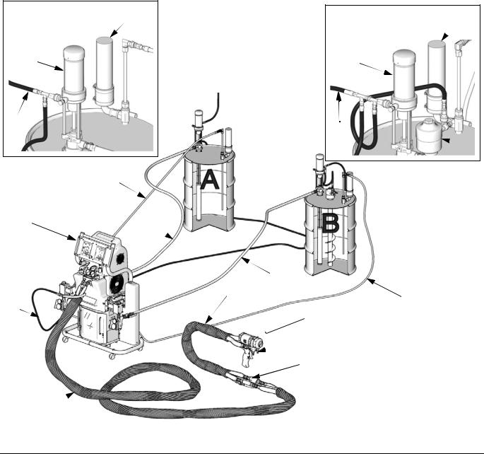
Key for FIG. 1
AReactor Proportioner
BHeated Hose
CFluid Temperature Sensor (FTS)
DHeated Whip Hose
EFusion Spray Gun
FGun Air Supply Hose
A Side Supply Detail
M
K 
G
ti7820a 2
G Feed Pump Air Supply Lines
JFluid Supply Lines
KFeed Pumps
LAgitator
MDesiccant Dryer
P Gun Fluid Manifold (part of gun)
R Circulation Lines
B Side Supply Detail M
K 
G
 L
L
R 
A J
J 
 J
J
D
R
F
 E
E

 P
P
 C*
C*
* Shown exposed for clarity.
Wrap with tape during operation.
B
ti10000a
FIG. 1: Typical Installation, with circulation
14 |
312062W |

Typical Installation, without circulation
Typical Installation, without circulation
Key for FIG. 2
A |
Reactor Proportioner |
H |
Waste Containers |
B |
Heated Hose |
J |
Fluid Supply Lines |
C |
Fluid Temperature Sensor (FTS) |
K |
Feed Pumps |
D |
Heated Whip Hose |
L |
Agitator |
E |
Fusion Spray Gun |
M |
Desiccant Dryer |
F |
Gun Air Supply Hose |
N |
Bleed Lines |
G |
Feed Pump Air Supply Lines |
P |
Gun Fluid Manifold (part of gun) |
A Side Supply Detail |
B Side Supply Detail |
|
|
K |
K |
M |
G |
G |
|
L |
||
|
||
ti7821a 2 |
ti7821a 3 |
J 
A 
|
|
J |
F |
|
D |
N |
H |
|
|
|
E |
|
|
P |
|
|
C* |
|
|
* Shown exposed for clarity. |
|
|
Wrap with tape during operation. |
B |
|
ti10001a |
FIG. 2: Typical Installation, without circulation
312062W |
15 |
Component Identification
Component Identification
Key for FIG. 3
BA Component A Pressure Relief Outlet
BB Component B Pressure Relief Outlet EC Heated Hose Electrical Connector
EM Electric Motor, Fan, and Belt Drive (behind shroud)
FA Component A Fluid Manifold Inlet (on left side of manifold block)
FB Component B Fluid Manifold Inlet FH Fluid Heater (behind shroud)
FM Reactor Fluid Manifold
FP Feed Inlet Pressure Gauge FS Feed Inlet Strainer
FT Feed Inlet Temperature Gauge FV Fluid Inlet Valve (B side shown)
GA Component A Outlet Pressure Gauge
GB Component B Outlet Pressure Gauge HA Component A Hose Connection
HB Component B Hose Connection HC Hydraulic Pressure Control
HP Hydraulic Pressure Gauge
LR ISO Lube Pump Reservoir MC Motor Control Display
MP Main Power Switch
OP Overpressure Rupture Disk Assembly (on rear of A and B pumps)
PA Component A Pump
PB Component B Pump RS Red Stop Button
SA Component A PRESSURE RELIEF/SPRAY Valve SB Component B PRESSURE RELIEF/SPRAY Valve SC Fluid Temperature Sensor Cable
SN Serial Number Plate (one inside cabinet, one on right side of cabinet)
SR Electrical Cord Strain Relief
TA Component A Pressure Transducer (behind gauge GA) TB Component B Pressure Transducer (behind gauge GB) TC Temperature Control Display
TD Oil Cooler
16 |
312062W |
Loading...