

Page 1
INSTRUCTIONS
309XXX
KEEP FOR REFERENCE.
Read this and all related manuals for
important warnings and instructions.
INSTRUCTIONS
First choice when
quality counts.
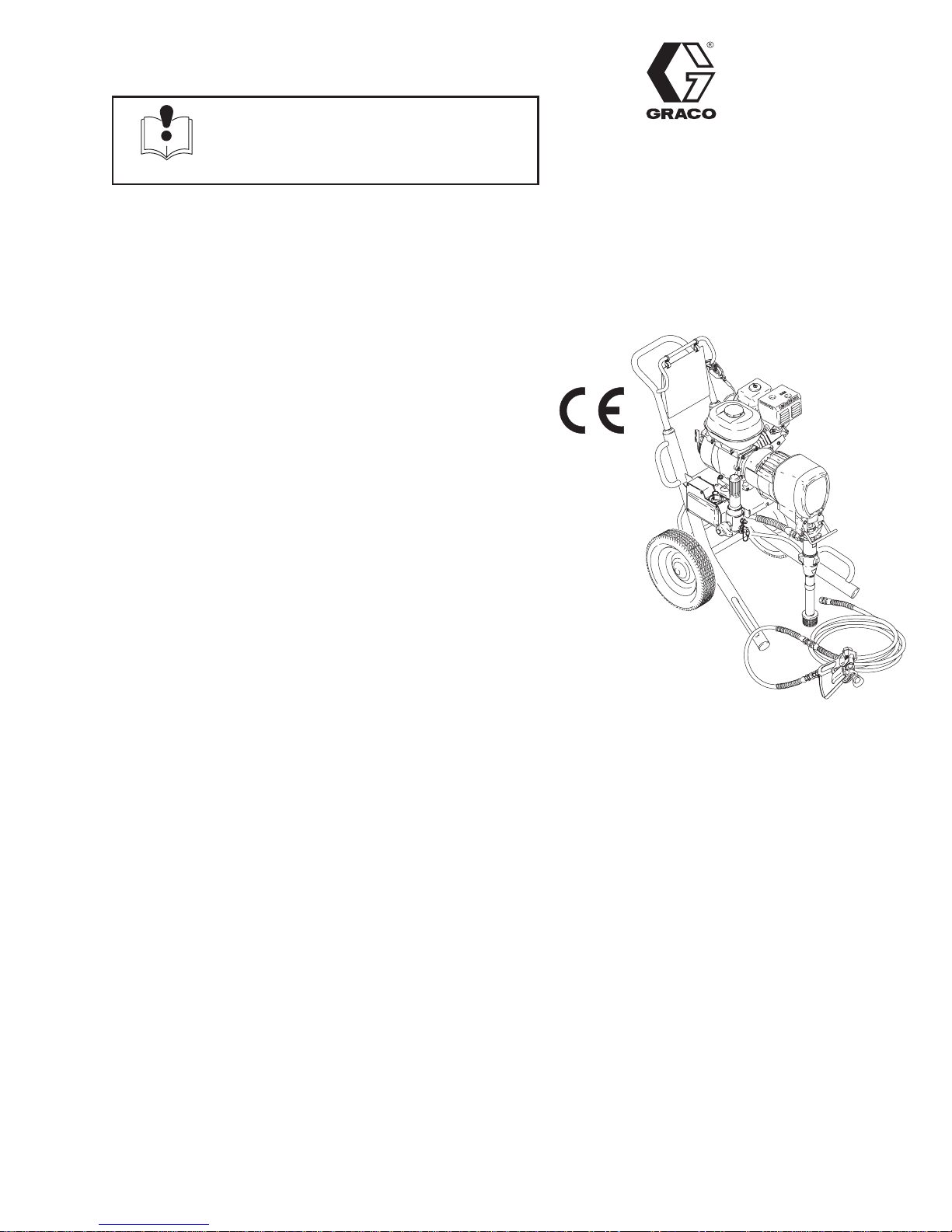
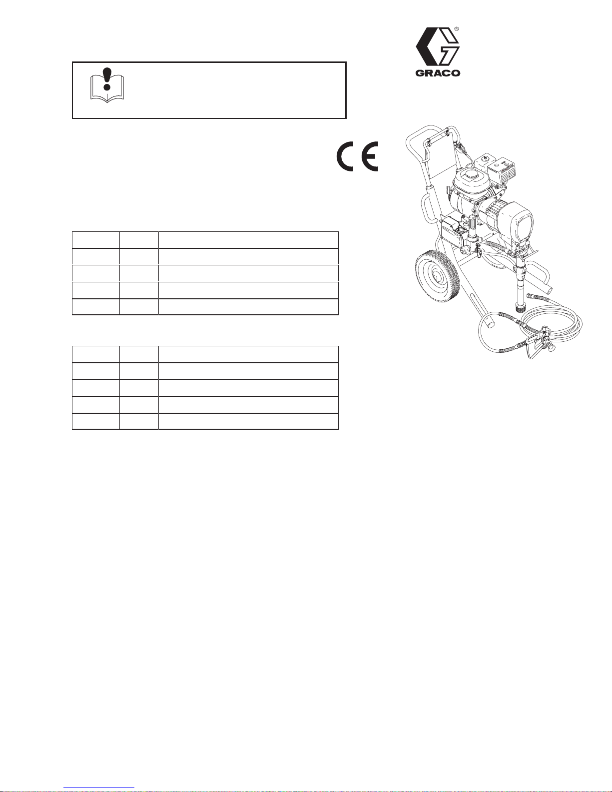
GMaxr 3900, 5900, 5900HD, 7900
Airless Paint Sprayers
3300 psi (227 bar, 22.7 MPa ) Maximum Working Pressure
Table of Manuals
Operation 308867. . . . . . . . . . . . . . . . . . . . . . . . . . . . . . .
Displacement Pump 308798. . . . . . . . . . . . . . . . . . . . . .
Spray Gun 307614. . . . . . . . . . . . . . . . . . . . . . . . . . . . . .
Spray Tip 308644. . . . . . . . . . . . . . . . . . . . . . . . . . . . . . . .
PC Board 308919. . . . . . . . . . . . . . . . . . . . . . . . . . . . . . .
Drain Valve Kit 308961. . . . . . . . . . . . . . . . . . . . . . . . . . .
Rev. A
t
Model 232621
8695A
GRACO INC. P.O. BOX 1441 MINNEAPOLIS, MN 55440–1441
ECOPYRIGHT 1999, GRACO INC.
Graco Inc. is registered to I.S. EN ISO 9001
Page 2
OPERATION – UTILIZAÇÃO
308867
FONCTIONNEMENT –FUNCIONAMIENTO
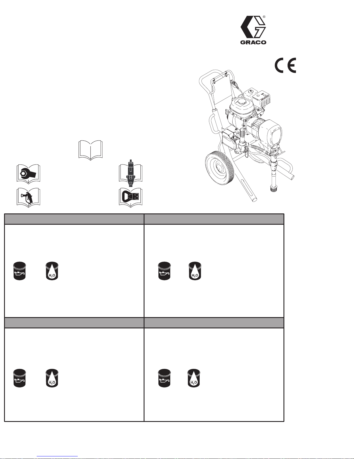
GMaxr 3900, 5900, 5900HD, 7900
3300 psi (228 bar, 22.8 MPa) Maximum Working Pressure
Pressão Máxima De Trabalho De 3300 psi (228 bar , 22,8 MPa)
Pression Maximale De Service 3300 lb/po2 (228 bar, 22.8 MPa)
3300 psi (228 bar, 22,8 MPa) Presión Máxima De Operación
232610, 232611, 232612, 232613*
232620, 232621, 232622, 232623, 232627, 232628*
232630, 232631, 232632, 232633{
All models not available in all countries
Nem todos os modelos existem à disposição em todos os países
T ous les modèles ne sont pas disponibles dans tous les pays
Hay modelos que no se distribuyen en todos los países
Related manuals
Manuais associados
Manuels afférents
Manuales relacionados
*308868. . . . . . .
{308870. . . . . . .
307614. . . . . . .
308798. . . . . . .
308644. . . . . . .
Rev. C
232620
INSTRUCTIONS
READ ALL INSTRUCTION AND WARNINGS
BEFORE SETTING UP OR OPERATING THIS UNIT.
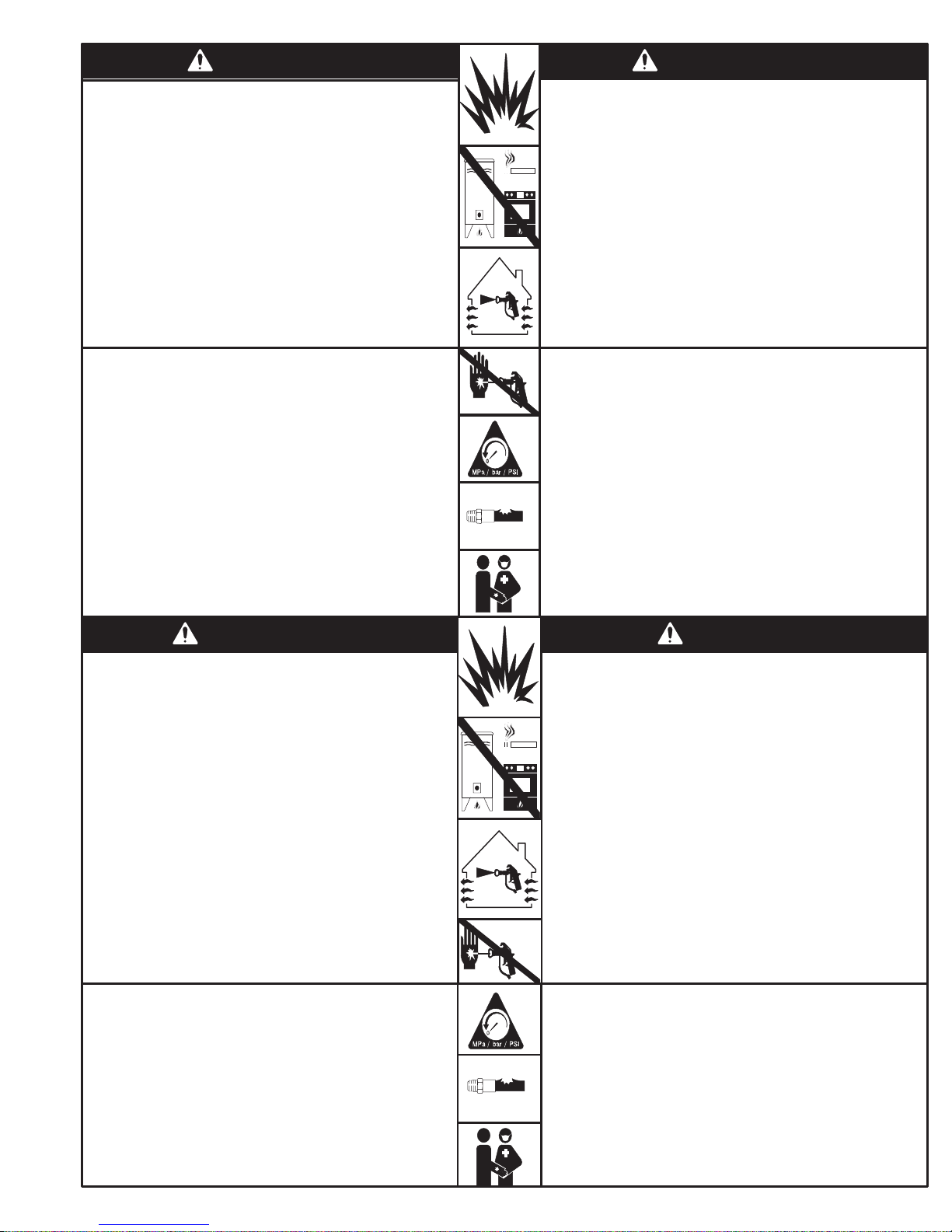
You need:
S two adjustable wrenches
S two 5 gallon (20 liters) metal pails
S Compatible cleaning fluids
LatexOil Base
Clothing:
S respirator
S safety glasses
Fuel & oil specifications:
S Unleaded gasoline octane
86 or higher
S Do not use gasolines
containing methanol.
S SAE 10W–40
Operating Consideration:
S Always keep sprayer upright
while operating or transporting
INSTRUCTIONS
LIRE TOUTES LES INSTRUCTIONS ET A VERTISSEMENTS
AVANT DE PRÉPARER OU F AIRE FONCTIONNER CET
Matériel requis:
S Deux clés à molette
S Deux seaux métalliques de 5 gallons
(20 litres)
S Nettoyants liquides compatibles
APPAREIL.
Spécifications des carburants
et des huiles:
S Essence sans plomb, indice
d’octane 86 et supérieur
S Ne pas utiliser d’essences
contenant du méthanol
S SAE 10W–40
INSTRUÇÕES
LEIA TODAS AS INSTRUÇÕES E ADVERTÊNCIAS
ANTES MONT AR OU UTILIZAR EST A UNIDADE.
Você precisa de:
S Duas chaves inglesas
S Dois baldes metálicos de 20 litros
S Líquidos de limpeza compatíveis
À base de óleo Látex
Vestuário:
S Máscara de respiração
S Óculos protetores
Especificações do combustível
e óleo:
S Gasolina sem chumbo de
86 octanas ou mais
S Não use gasolina contendo
metanol
S SAE 10W–40
Conselho para a operação:
S Mantenha o pulverizador sempre
na vertical quando o estiver
utilizando ou transportando
INSTRUCCIONES
LEA TODAS LAS INSTRUCCIONES Y ADVERTENCIAS
ANTES DE PREP ARAR U OPERAR ESTA UNIDAD.
Necesita:
S Dos llaves ajustables
S Dos recipientes metálicos de
20 litros (5 galones)
S Fluidos de limpieza compatibles
Especificaciones de combustible
y aceite:
S Gasolina sin plomo de octanaje
86 o superior
S No use gasolina que
contengan metanol
S SAE 10W–40
Émail (base d’huile)
Protection personnelle:
S Respirateur
S Lunettes de protection
Latex
Précautions:
S T oujours maintenir le bec
pulvérisateur vers le haut
pendant le fonctionnement
ou le transport
GRACO INC. P.O. BOX 1441 MINNEAPOLIS, MN 55440–1441
Graco Inc. is registered to I.S. EN ISO 9001
Óleo Látex
Vestuario:
S Mascarilla
S Gafas de seguridad
Consideraciones para la operación:
S Mantenga siempre el pulverizador
en posición vertical mientras lo
opere o transporte
Page 3
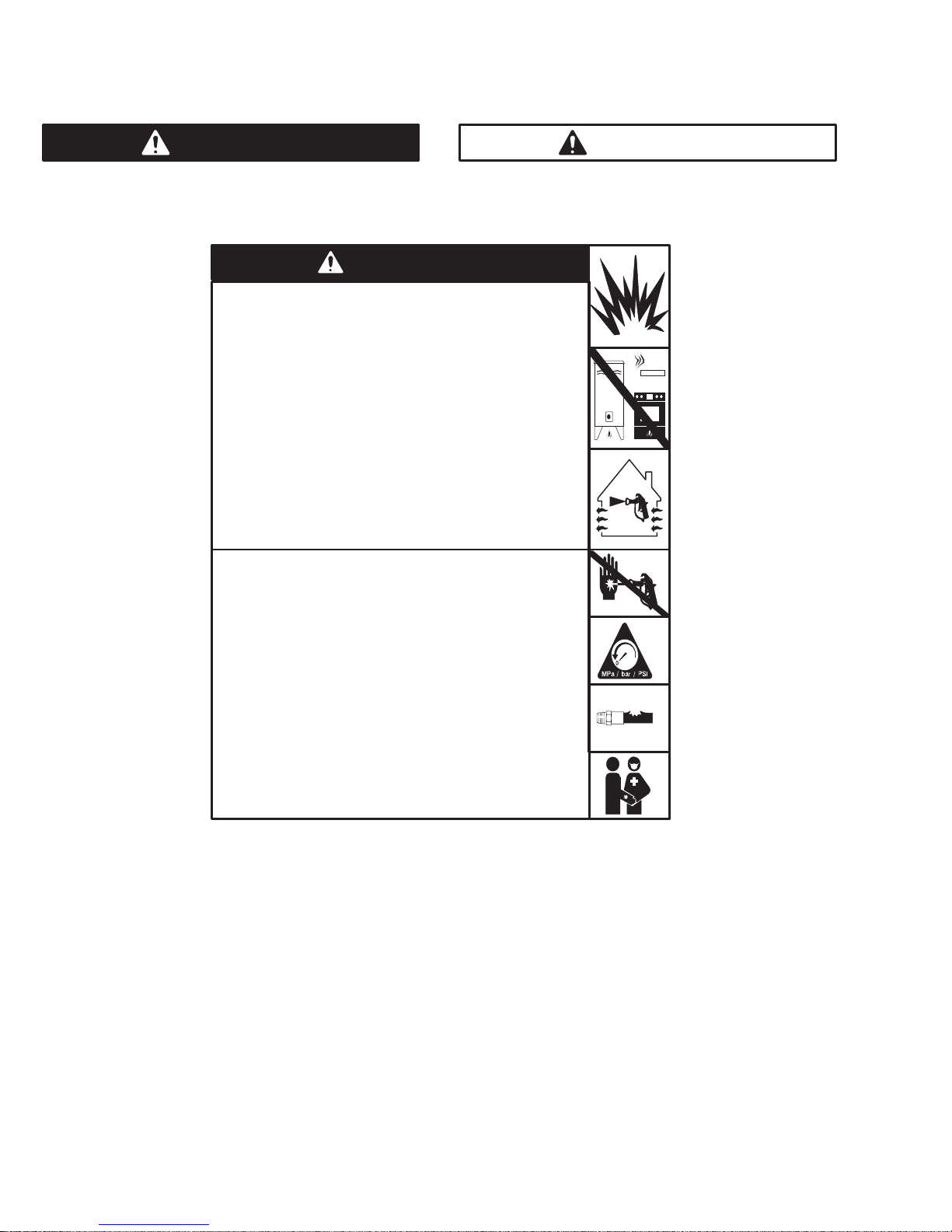
WARNING
Fire and explosion can occur when spraying or flushing flammable
fluid in an area where air circulation is poor and flammable vapors
can be ignited by an open flame or sparks.
To help prevent a fire and explosion:
Use outdoors or in an extremely well ventilated area.
Do not use 1,1,1–trichloroethane, methylene chloride, other
halogenated hydrocarbon solvents or fluids containing such
solvents in pressurized aluminum equipment. Such use could
result in a chemical reaction, with the possibility of explosion.
Remove, extinguish or unplug all ignition sources;
tape wall switches. Do not smoke in spray area.
Never fill fuel tank while the engine is running or hot.
Ground Sprayer, object being sprayed, paint and solvent pails.
Hold gun firmly to side of a grounded pail when triggering into pail.
Use only conductive airless paint hose.
Never run engine in inclosed area.
ADVERTÊNCIA
Poderá ocorrer incêndio e explosão quando for pulverizado ou injetado
líquido inflamável numa área onde houver má circulação de ar; vapores
inflamáveis poderão incendiar-se a partir de uma chama ou fagulhas a
descoberto.
Para ajudar a evitar incêndio e explosão:
Utilize no exterior ou numa área muito bem ventilada.
Não utilize 1,1,1–tricloroetano, cloreto de metileno, outros solventes de
hidrocarbonetos halogenados ou líquidos contendo tais solventes em
equipamento de alumínio pressurizado. Tal utilização poderá resultar
numa reação química, com possibilidade de explosão.
Retire, elimine ou desligue todas as fontes de ignição; coloque fita
adesiva na tomada da parede. Não fume na área de pulverização.
Nunca abasteça o depósito de combustível com o motor em funciona-
mento ou quente.
Ponha em contato com a terra o pulverizador, o objeto a ser pulveriza-
do, e os baldes de tinta e de solventes.
Segure a pistola firmemente de encontro ao lado de um balde em contato
com a terra, quando estiver descarregando para dentro do mesmo.
Utilize somente tubos flexíveis condutores para pintura a alta pressão.
Nunca faça funcionar o motor numa área fechada.
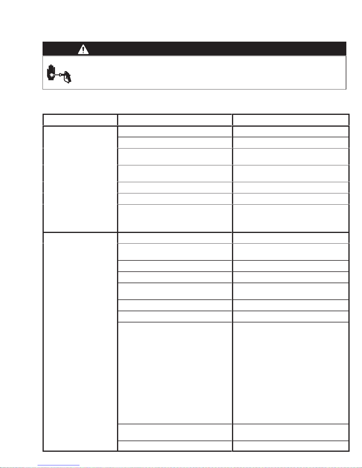
Fluid injection is a serious injury! If high pressure fluid pierces
your skin, the injury might look like “just a cut”. But it is a serious
wound! Get immediate medical attention.
To help prevent injection, always:
Engage trigger safety latch when not spraying.
Point gun away from yourself or anyone else.
Relieve pressure before checking or repairing any leak.
Relieve pressure when you turn off the sprayer or stop spraying.
Do not use components rated less than system
Working Pressu re
Never allow children to use this unit. If you are injured using this
equipment, get immediate medical treatment.
Maximum
MISE EN GARDE
Risque d’incendie et d’explosion imminent pendant la pulvérisation
ou le rinçage à pression de fluides inflammables dans une zone à mauvaise circulation d’air et en présence de gaz inflammables pouvant
s’allumer par une flamme nue ou des étincelles.
Pour éviter les risques d’incendie et d’explosion:
Manipuler les fluides à l’air libre ou dans une zone extrêmement
bien aérée.
Ne jamais utiliser de trichloroéthane 1,1,1, de chlorure de méthylène,
d’autres solvants à base d’hydrocarbures halogénés, ni de produits
contenant de tels solvants dans un équipement sous pression en
aluminium. Cela pourrait provoquer une réaction chimique avec risque
d’explosion.
Retirer, éteindre ou déboucher toute source d’inflammation, recouvrir
tout interrupteur mural avec du ruban adhésif. Ne pas fumer dans la
zone de pulvérisation.
Ne jamais remplir le réservoir d’essence lorsque le moteur est chaud
ou en marche.
Mettre à la terre le pulvérisateur, l’objet à pulvériser ainsi que les
seaux de peinture et de solvants.
Tenir le pistolet fermement contre la paroi d’un seau mis à la
terre lorsqu’on pulvérise dans le seau.
N’utiliser qu’un flexible pour peinture pulvérisée sans air.
Ne jamais mettre en marche un moteur dans une zone fermée.
A injeção de líquido é um ferimento grave! Se o líquido a alta pressão penetrar na sua pele, o ferimento poderá parecer “simplesmente
um corte”. Mas é um ferimento grave! Procure o médico imediatamente.
Para ajudar a evitar injeção de líquido, faça sempre o seguinte:
Engate o trinco de segurança do gatilho quando não estiver pulveri-
zando.
Sempre aponte a pistola para longe de você mesmo(a) ou de outras
pessoas.
Alivie a pressão antes de verificar ou reparar qualquer vazamento.
Alivie a pressão quando desligar o pulverizador ou parar de pulverizar.
Não utilize componentes classificados para uma pressão nominal
inferior à pressão máxima de trabalho dos sistemas.
Nunca permita que crianças utilizem esta unidade. Se sofrer algum
ferimento durante a utilização deste equipamento, procure o médico
imediatamente.
ADVERTENCIA
Pueden ocurrir incendios y explosiones cuando se pulveriza fluido inflamable o cuando se lava con este tipo de fluido en un área donde la
circulación de aire es deficiente y los vapores inflamables se pueden encender al contacto con el fuego o chispas.
Para prevenir incendios y explosiones:
Use en espacios abiertos o en un área muy bien ventilada.
No utilice nunca tricloretano–1,1,1, cloruro de metileno, u otros di-
solventes a base de hidrocarburos halógenos o fluidos que contengan
tales disolventes en un equipo a presión de aluminio. El uso de estas
sustancias puede provocar una intensa reacción química, con riesgos
de explosión.
Retire, apague o desconecte todas las fuentes de ignición; asegure el
interruptor de la pared con cinta. No fume en el área de pulverización.
Nunca llene el estanque de combustible mientras el motor esté en
marcha o caliente.
Ponga a tierra el pulverizador, el objeto que recibe el chorro pulverizado,
las cubetas de pintura y disolvente.
Sostenga firmemente la pistola a un lado de la cubeta puesta a
tierra cuando dispare dentro de ella.
Use solamente mangueras para pintura conductora sin aire.
Nunca haga andar el motor dentro de un área cerrada.
L’injection de fluide constitue une lésion grave! Si un fluide haute
pression perce la peau, la blessure peut paraître comme une
«simple coupure». Mais i l s’agit bien d’une lés i on grave! Consul t er
immédiatement un médecin.
Pour éviter les risques d’injection, toujours:
Bloquer le loquet de sécurité de la gâchette à la fin de la pulvérisation.
Pointer le pistolet loin de soi-même et toute autre personne à proximité
Décharger la pression avant de vérifier ou réparer une fuite.
Décharger la pression après la mise hors tension du pulvérisateur ou
à la fin de la pulvérisation.
Ne pas utiliser de composants dont la pression nominale est inférieure
à la pression maximale de service du système.
Ne jamais permettre aux enfants d’utiliser cet appareil. En cas de blessure pour avoir utilisé cet appareil, consulter immédiatement un médecin.
¡La inyección de fluido en la piel es una lesión seria! Si fluido de
alta presión le penetra la piel, la lesión podría parecer “sólo un
corte”. ¡Es una lesión seria! Consulte de inmediato al médico.
Para prevenir la inyección en la piel, siempre:
Enganche el seguro del gatillo cuando no use el pulverizador.
No apunte la pistola ni a sí mismo ni a los demás.
Alivie la presión antes de inspeccionar o reparar cualquier filtración.
Alivie la presión cuando apague el pulverizador o deje de usarlo.
No use componentes cuya capacidad nominal sea inferior a la
presión máxima de operación del sistema.
No permita que niños usen esta unidad. Si se lesiona usando este
equipo, sométase de inmediato a tratamiento médico.
3308867
Page 4
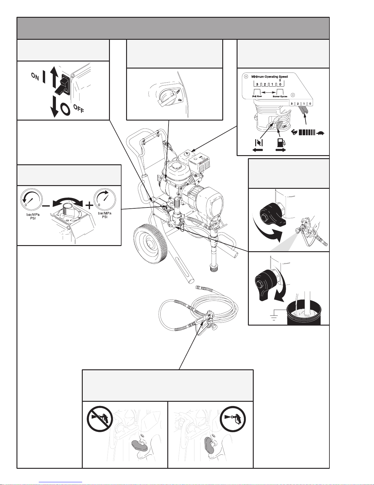
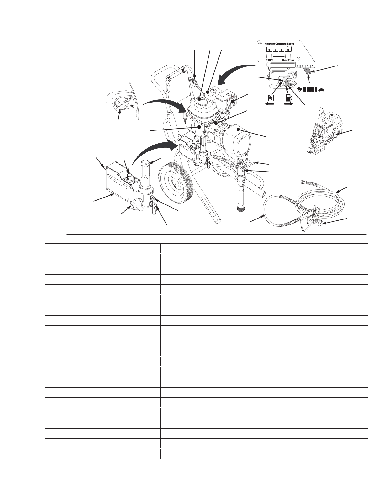
CONTROLS / CONTROLES / COMMANDES / CONTROLES
On/Off Switch Aan/Uit Schakelaar
Interrupteur Marche/Arrêt
Ein-Aus-Schalter
Pressure Control / Controle da pressão /
Système de contrôle de la pression /
Dispositivo de control de la presión
On/Off Switch
Interruptor de ligar e desligar
Interrupteur marche/arrêt
Interruptor de encendido/apagado
Engine Controls
Controles do motor
Commandes de moteur
Controles del motor
Drain V alve
Válvula de drenagem
Vidange
Válvula de vaciado
Trigger Lock
Fecho do gatilho
Loquet de sécurité
Seguro del gatillo
4 308867
8695A
Page 5
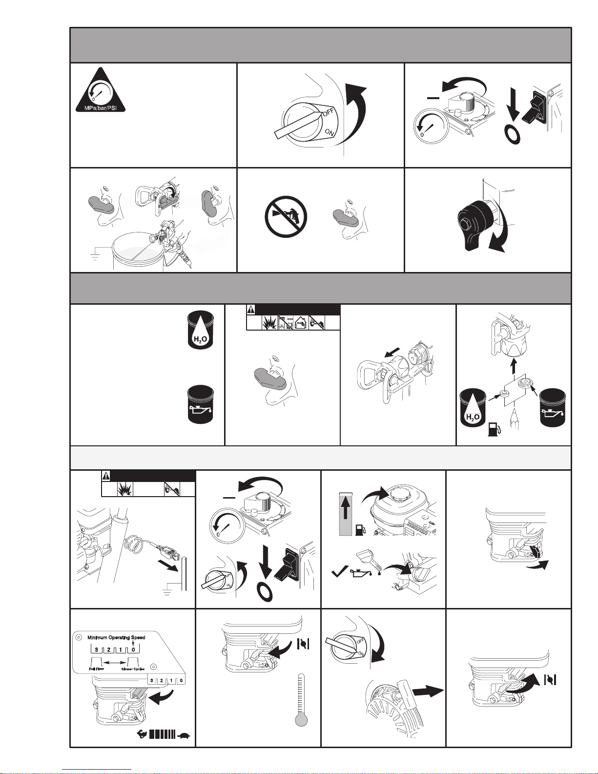
PRESSURE RELIEF / ALÍVIO DE PRESSÃO / DÉCHARGE DE PRESSION /
ALIVIO DE LA PRESIÓN 1→5
Follow 1–5 when you
stop spraying.
Siga os passos de 1–5
quando parar de pulverizar.
Suivre les étapes 1 à 5 lorsqu’on arrête
de pulvériser.
Siga los pasos 1–5 cuando deje de usar
el pulverizador.
3
12
54
STARTUP / P ARTIDA / DÉMARRAGE / PUESTA EN MARCHA 1→24
WARNING ADVERTÊNCIA
Flush with warm soapy water.
Faça a descarga com água
morma e sabão dissolvido.
Rincer avec de l’eau tiède
savonneuse.
Enjuague con agua tibia con
jabón.
1
MISE EN GARDE ADVERTENCIA
2
3
Flush with mineral spirits.
Faça a descarga com
álcool mineral.
Rincer avec une eseence
minérale.
Enjuague con alcohol
mineral.
Start Engine / Partida do motor / Démarrage / Partida del motor 4→11
WARNING ADVERTÊNCIA
MISE EN GARDE ADVERTENCIA
8
54 6
9
10
7
11
Cold Engine Starts
Partida do motor a frio
Démarrages à froid
Partida del motor en frío
5308867
Page 6
Flush / Descarga / Vidange / Enjuague 12→19
12
16
WASTE
RESÍDUOS
À JETER
DESECHO
RESÍDUOS
À JETER
DESECHO
WASTE
FLUSH
DESCARGA
VIDANGE
ENJUAGUE
20 SEC.
13
Start Engine
Partida do motor
Démarrage
Partida del motor
17
FLUSH
DESCARGA
VIDANGE
ENJUAGUE
1 MIN.
14
18
FLUSH
DESCARGA
VIDANGE
ENJUAGUE
10 SEC.
15
19
FLUSH
DESCARGA
VIDANGE
ENJUAGUE
Prime / Preparação / Amorçage / Cebado 20→23
WARNING ADVERTÊNCIA
MISE EN GARDE ADVERTENCIA
WASTE
AFVAL
REBUT
ABFAL
PAINT
TINTA
PEINTURE
PINTURA
21 2220
WASTE
AFVAL
REBUT
ABFAL
Watch for paint
Cuidado com a tinta
Vérifier l’arrivée de la peinture
Observe cuando salga pintura
PAINT
TINTA
PEINTURE
PINTURA
23
WASTE
AFVAL
REBUT
ABFAL
Watch for paint
Cuidado com a tinta
Vérifier l’arrivée de la peinture
Observe cuando salga pintura
SPRAY / PULVERIZAÇÃO / PULVÉRISATION / PULVERISACIÓN 1→4
WARNING ADVERTÊNCIA
1234
MISE EN GARDE ADVERTENCIA
6 308867
Page 7
CLEAR CLOG / DESOBSTRUÇÃO / DÉCRASSEMENT /
DESTAPAR
WARNING ADVERTÊNCIA
1 23
MISE EN GARDE ADVERTENCIA
CHANGE P AINT / TROCA DE TINTA / CHANGEMENT
DE PEINTURE / CAMBIAR PINTURA
231
Flush
Descarga
Pressure Relief
Alívio de pressão
Vidange
Décharge de pression
Alivio de la presión
Enguaje
SHUTDOWN / DESATIVAÇÃO / ARRÊT / PARADA
WARNING ADVERTÊNCIA
MISE EN GARDE ADVERTENCIA
1
Pressure Relief
Alívio de pressão
Décharge de pression
Alivio de la presión
2534
Prime
Preparação
Amorçage
Cebado
6
7
Flush
Descarga
Vidange
Enguaje
FLUSH
DESCARGA
VIDANGE
ENJUAGUE
98
20 SEC.
Pressure Relief
Alívio de pressão
Décharge de pression
Alivio de la presión
7308867
Page 8
10 1 1 12
FLUSH
FLUSH
DESCARGA
SPOELEN
VIDANGE
RINÇAGE
ENJUAGUE
SPÜLUNG
13
14 16
18
Pressure Relief
Alívio de pressão
Décharge de pression
Alivio de la presión
19 20 21
Mineral Spirits
Álcool mineral
Essence minérale
Alcohol mineral
Mineral Spirits
White spirit
Lösungsbenzin
Thinner
1715
20 SEC.
WASTE
RESÍDUOS
À JETER
DESECHO
8 308867
Page 9

Graco Standard W arranty Garantia Standard da Graco
Garantie standard de Graco Garantía estándar Graco
Graco warrants all equipment referenced in this document which is manufactured by Graco and bearing its name to be free from defects in material and
workmanship on the date of sale by an authorized Graco distributor to the original purchaser for use. With the exception of any special, extended, or
limited warranty published by Graco, Graco will, for a period of twelve months from the date of sale, repair or replace any part of the equipment determined
by Graco to be defective. This warranty applies only when the equipment is installed, operated and maintained in accordance with Graco’s written recommendations.
This warranty does not cover, and Graco shall not be liable for general wear and tear, or any malfunction, damage or wear caused by faulty installation,
misapplication, abrasion, corrosion, inadequate or improper maintenance, negligence, accident, tampering, or substitution of non–Graco component
parts. Nor shall Graco be liable for malfunction, damage or wear caused by the incompatibility of Graco equipment with structures, accessories, equipment or materials not supplied by Graco, or the improper design, manufacture, installation, operation or maintenance of structures, accessories, equipment or materials not supplied by Graco.
This warranty is conditioned upon the prepaid return of the equipment claimed to be defective to an authorized Graco distributor for verification of the
claimed defect. If the claimed defect is verified, Graco will repair or replace free of charge any defective parts. The equipment will be returned to the
original purchaser transportation prepaid. If inspection of the equipment does not disclose any defect in material or workmanship, repairs will be made at a
reasonable charge, which charges may include the costs of parts, labor , and transportation.
THIS WARRANTY IS EXCLUSIVE, AND IS IN LIEU OF ANY OTHER W ARRANTIES, EXPRESS OR IMPLIED, INCLUDING BUT NOT LIMITED T O
WARRANTY OF MERCHANTABILITY OR WARRANTY OF FITNESS FOR A PARTICULAR PURPOSE.
Graco’s sole obligation and buyer’s sole remedy for any breach of warranty shall be as set forth above. The buyer agrees that no other remedy (including,
but not limited to, incidental or consequential damages for lost profits, lost sales, injury to person or property, or any other incidental or consequential loss)
shall be available. Any action for breach of warranty must be brought within two (2) years of the date of sale.
GRACO MAKES NO WARRANTY, AND DISCLAIMS ALL IMPLIED W ARRANTIES OF MERCHANTABILITY AND FITNESS FOR A P ARTICULAR
PURPOSE, IN CONNECTION WITH ACCESSORIES, EQUIPMENT, MATERIALS OR COMPONENTS SOLD BUT NOT MANUFACTURED BY
GRACO. These items sold, but not manufactured by Graco (such as electric motors, switches, hose, etc.), are subject to the warranty, if any , of their
manufacturer. Graco will provide purchaser with reasonable assistance in making any claim for breach of these warranties.
In no event will Graco be liable for indirect, incidental, special or consequential damages resulting from Graco supplying equipment hereunder , or the
furnishing, performance, or use of any products or other goods sold hereto, whether due to a breach of contract, breach of warranty, the negligence of
Graco, or otherwise.
PARA CLIENTES BRASILEIROS DA GRACO
As partes confirmam que solicitaram que o presente documento, assim como todos os demais documentos, notas e processos legais inseridos, atribuídos ou instituídos de acordo com o mesmo ou relacionados direta ou indiretamente com o este documento, sejam redigidos em inglês.
AUX CLIENTS DE GRACO AU CANADA
Les parties conviennent avoir demandé que le présent document, ainsi que tout autre document, avis et procédures judiciaires inclus, donnés dans les
présentes ou institués en vertu des présentes, ou en relation directe ou indirecte aux présentes, soient rédigés en anglais.
PARA CLIENTES DE GRACO EN COLOMBIA
Las partes reconocen que han solicitado que el presente documento, como asimismo todos los documentos, notificaciones y compromisos legales que
se suscriban, presentados o instituidos por el presente o relacionados directa e indirectamente con éste, sean redactados en inglés.
ADDITIONAL WARRANTY COVERAGE / COBERTURA DE GARANTIA ADICIONAL / GARANTIE PROLONGÉE /
COBERTURA ADICIONAL DE LA GARANTÍA /
Graco does provide extended warranty and wear warranty for products described in the “Graco Contractor Equipment Warranty Program”.
A Graco fornece prorrogação de garantia e garantia de desgaste para os produtos descritos no “Graco Contractor Equipment Warranty Program”
(Programa de garantia de equipamento do empreiteiro da Graco).
Graco n’offre pas de garantie prolongée ni de garantie contre l’usure pour les produits décrits dans le “Programme de garantie des équipements pour
entrepreneur de Graco”.
Graco ofrece una garantía extendida y una garantía de desgaste para los productos consignados en el “Programa de Garantía de Equipo Graco para
Contratistas”.
TO PLACE AN ORDER OR FOR SERVICE
PARA EFETUAR ENCOMENDAS OU PARA ASSISTÊNCIA TÉCNICA
POUR PLACER UNE COMMANDE OU DEMANDER DU SERVICE
PARA REMITIR UN PEDIDO O SOLICITAR SERVICIO
, contact your Graco distributor.
, contate o seu distribuidor da Graco.
, contactez votre distributeur Graco.
, póngase en contacto con el distribuidor de Graco.
All written and visual data contained in this document reflects the latest product information available at the time of publication. Graco reserves the
T odos os dados escritos e visuais contidos neste documento refletem as mais recentes informações sobre o produto disponíveis na época da
T oute information écrite et graphique incluse dans ce document reflète les caractéristiques les plus récentes des produits au moment d’aller sous
T oda la información escrita y visual contenida en este documento refleja la información de producto más reciente manejada al momento de la
publicação. A Graco reserva-se o direito de efetuar alterações em qualquer momento sem aviso prévio.
presse. Graco se réserve le droit d’apporter des modifications en tout temps sans avis.
publicación. Graco se reserva el derecho de introducir cambios en cualquier momento sin aviso.
Foreign Offices: Belgium, England, Korea, France, Germany, Hong Kong, Japan
Escritórios estrangeiros: Bélgica, Inglaterra, Coréia, França, Alemanha, Hong Kong, Japão
International: Belgique, Angleterre, Corée, France, Allemagne, Hong Kong, Japon
Oficinas internacionales: Bélgica, Inglaterra, Corea, Francia, Alemania, Hong Kong, Japón
GRACO INC. P.O. BOX 1441 MINNEAPOLIS, MN 55440–1441
right to make changes at any time without notice.
Sales Offices: Minneapolis, Detroit
Escritórios de Vendas: Minneapolis, Detroit
Bureaux des ventes: Minneapolis, Détroit
Oficina de ventas: Minneapolis, Detroit
http://www.graco.com
PRINTED IN USA 308867 November 1998, Revised March 1999
9308867
Page 10
INSTRUCTIONS-REPAIR
308868
KEEP FOR REFERENCE.
Read this and all related manuals for
important warnings and instructions.
INSTRUCTIONS
GMaxr 3900 and 5900
Airless Paint Sprayers
3300 psi (227 bar, 22.7 MPa ) Maximum Working Pressure
GMax 3900
Model Series Description
232610 A Hi-Boy
232611 A Hi-Boy with RAC IV tip, gun and hose
232612 A Lo-Boy
232613 A Lo-Boy with RAC IV tip, gun and hose
GMax 5900
Model Series Description
232620 A Hi-Boy
232621 A Hi-Boy with RAC IV tip, gun and hose
232622 A Lo-Boy
232623 A Lo-Boy with RAC IV tip, gun and hose
Rev. A
First choice when
quality counts.
Model 232621
All models are not available in all countries
U.S. PATENT NO. 4,323,741; 4,397,610 PATENTED
1983, CANADA AND OTHER P ATENTS PENDING
t
8695A
Related Manuals
Operation 308867. . . . . . . . . . . . . . . . . . . . . . . . . .
Displacement Pump 308798. . . . . . . . . . . . . . . . .
Spray Gun 307614. . . . . . . . . . . . . . . . . . . . . . . . .
Spray Tip 308644. . . . . . . . . . . . . . . . . . . . . . . . . . .
PC Board 308816. . . . . . . . . . . . . . . . . . . . . . . . . .
Drain Valve Kit 308961. . . . . . . . . . . . . . . . . . . . . .
Warnings and Cautions 2. . . . . . . . . . . . . . . . . . . . . . . . .
Component Identification and Function 3. . . . . . . . . . . .
Maintenance 4. . . . . . . . . . . . . . . . . . . . . . . . . . . . . . . . . . .
Troubleshooting 5. . . . . . . . . . . . . . . . . . . . . . . . . . . . . . . .
Repair
Bearing Housing & Connecting Rod 7. . . . . . . . . . . . .
Drive Housing 8. . . . . . . . . . . . . . . . . . . . . . . . . . . . . . . .
Pinion Assembly/Rotor/Field/Shaft/Clutch 9. . . . . . . .
Clamp 10. . . . . . . . . . . . . . . . . . . . . . . . . . . . . . . . . . . . .
Clutch Housing 1 1. . . . . . . . . . . . . . . . . . . . . . . . . . . . . .
Engine 1 1. . . . . . . . . . . . . . . . . . . . . . . . . . . . . . . . . . . . .
Pressure Control 12. . . . . . . . . . . . . . . . . . . . . . . . . . . .
GRACO INC. P.O. BOX 1441 MINNEAPOLIS, MN 55440–1441
Table of Contents
Displacement Pump 14. . . . . . . . . . . . . . . . . . . . . . . . .
Parts
GMax 3900 & GMax 5900 Hi-Boy Sprayers 15. . . . .
Pinion Assembly 17. . . . . . . . . . . . . . . . . . . . . . . . . . . .
GMax 3900 & GMax 5900 Lo-Boy Sprayers 18. . . . .
Complete Sprayers 20. . . . . . . . . . . . . . . . . . . . . . . . . .
Pressure Control 21. . . . . . . . . . . . . . . . . . . . . . . . . . . .
Dimensions 23. . . . . . . . . . . . . . . . . . . . . . . . . . . . . . . . . . .
Technical Data 23. . . . . . . . . . . . . . . . . . . . . . . . . . . . . . . .
Graco Phone Number 23. . . . . . . . . . . . . . . . . . . . . . . . . .
Graco Warranty 24. . . . . . . . . . . . . . . . . . . . . . . . . . . . . . .
ECOPYRIGHT 1999, GRACO INC.
Graco Inc. is registered to I.S. EN ISO 9001
Page 11
Warnings and Cautions
Warning Symbol
WARNING
This symbol alerts you to the possibility of serious
injury or death if you do not follow the instructions.
WARNING
Fire and explosion can occur when spraying or flushing flammable
fluid in an area where air circulation is poor and flammable vapors
can be ignited by an open flame or sparks.
To help prevent a fire and explosion:
Use outdoors or in an extremely well ventilated area.
Do not use 1,1,1–trichloroethane, methylene chloride, other
halogenated hydrocarbon solvents or fluids containing such
solvents in pressurized aluminum equipment. Such use could
result in a chemical reaction, with the possibility of explosion.
Remove, extinguish or unplug all ignition sources;
tape wall switch. Do not smoke in spray area.
Never fill fuel tank while the engine is running or hot.
Ground Sprayer, object being sprayed, paint and solvent pails.
Hold gun firmly to side of a grounded pail when triggering into pail.
Use only conductive airless paint hose.
Never run engine in inclosed area.
Caution Symbol
CAUTION
This symbol alerts you to the possibility of damage to
or destruction of equipment if you do not follow the
instructions.
Fluid injection is a serious injury! If high pressure fluid pierces
your skin, the injury might look like “just a cut”. But it is a serious
wound! Get immediate medical attention.
To help prevent injection, always:
Engage trigger safety latch when not spraying.
Point gun away from yourself or anyone else.
Relieve pressure before checking or repairing any leak.
Relieve pressure when you turn off the sprayer or stop spraying.
Do not use components rated less than system
Working Pressu re
Never allow children to use this unit. If you are injured using this
equipment, get immediate medical treatment.
Maximum
3088682
Page 12
Component Identification and Function
202Main hose
203Whip end hose
204Contractor gun with RAC IV
DripLess tip guard and 517 size SwitchTip
K
A
M
X
Fig. 1
V
P
B
U
N
L
C
D
J
H
E
R
S
W
T
203
G
F
Model 232611
202
204
8696A
A Pressure Control Switch ON/OFF, enables/disables clutch function and pressure control
B Pressure Adjusting Knob Controls fluid outlet pressure
C Air Cleaner* Filters air entering the carburetor
D Fuel Tank* Uses 86 octane unleaded gasoline
E Muffler* Reduces noise of internal combustion
F Spark Plug Cable* Routes electrical current to spark plug
G Fuel Shutoff Lever* On/off lever to regulate fuel flow from gasoline tank to carburetor
H Choke* Enriches air/gasoline mixture for cold starting
J Throttle Lever* Adjusts engine speed for large or small orifice spray tips
K Engine Switch* Enables/disables engine operation
L Secondary Fluid Outlet Second hose and spray gun is connected here
M Pressure Control Controls clutch cycling to maintain fluid pressure.
N Primary Fluid Outlet Hose and spray gun is connected here
P Engine* 4–cycle gasoline engine
R Clutch Housing Transfers power from engine to drive assembly
S Drive Housing Transfers power from clutch to displacement pump
T Displacement Pump Provides fluid to be sprayed through spray gun
U Fluid Filter Filters fluid between source and spray gun
V Grounding Clamp and Wire Grounds sprayer system
W Pail Hanger Provides a hanger for paint pail
X Pressure Drain Valve Relieves fluid pressure when open
* For more detailed explanations of these controls, refer to the Honda Engines Owner’s Manual; supplied
Page 13

Maintenance
WARNING
INJECTION HAZARD
The system pressure must be manually
relieved to prevent the system from
starting or spraying accidentally. Fluid
under high pressure can be injected through the
skin and cause serious injury. To reduce the risk of
an injury from injection, splashing fluid, or moving
parts, follow the Pressure Relief Procedure
whenever you:
are instructed to relieve the pressure,
stop spraying,
check or service any of the system equipment,
or install or clean the spray tip.
Pressure Relief Procedure
1. Lock gun trigger safety.
2. Turn engine ON/OFF switch to OFF.
3. Move pressure control switch to OFF and turn
pressure control knob fully counterclockwise.
CAUTION
For detailed engine maintenance and specifications,
refer to separate Honda Engines Owner’s Manual,
supplied.
DAILY: Check engine oil level and fill as necessary.
DAILY: Check hose for wear and damage.
DAILY: Check gun safety for proper operation.
DAILY: Check pressure drain valve for proper opera-
tion.
DAILY: Check and fill the gas tank.
AFTER THE FIRST 20 HOURS OF OPERATION
Drain engine oil and refill with clean oil. Reference
Honda Engines Owner’s Manual for correct oil viscosity.
WEEKLY: Remove air filter cover and clean element.
Replace element, if necessary. If operating in an
unusually dusty environment: check filter daily and
replace, if necessary.
4. Unlock trigger safety. Hold metal part of gun firmly
to side of grounded metal pail, and trigger gun to
relieve pressure.
5. Lock gun trigger safety.
6. Open pressure drain valve. Leave valve open until
ready to spray again.
If you suspect that the spray tip or hose is completely
clogged, or that pressure has not been fully relieved
after following the steps above,
loosen tip guard retaining nut or hose end coupling to
relieve pressure gradually, then loosen completely.
Now clear tip or hose.
VERY SLOWLY
Replacement elements can be purchased from your
local HONDA dealer.
WEEKLY: Check level of TSL in displacement pump
packing nut. Fill nut, if necessary. Keep TSL in nut to
help prevent fluid buildup on piston rod and premature
wear of packings.
AFTER EACH 100 HOURS OF OPERATION:
Change engine oil. Reference Honda Engines Owner’s
Manual for correct oil viscosity.
SPARK PLUG: Use only BPR6ES (NGK) or
W20EPR–U (NIPPONDENSO) plug. Gap plug to
0.028 to 0.031 in. (0.7 to 0.8 mm). Use spark plug
wrench when installing and removing plug.
3088684
Page 14
Troubleshooting
WARNING
INJECTION HAZARD
To reduce risk of serious injury, including fluid injection or splashing in eyes or on skin, or injury from
moving parts, always follow Pressure Relief Procedure Warning, page 4, before checking, adjusting, cleaning or shutting down sprayer.
Check everything in chart before disassembling sprayer.
PROBLEM CAUSE SOLUTION
Engine won’t start
Engine operates, but disp
placement pump does not
operate
p
p
Engine switch is OFF Turn engine switch ON
Engine is out of gas Refill gas tank. Honda Engines Owner’s Manual.
Engine oil level is low Try to start engine. Replenish oil, if necessary.
Spark plug cable is disconnected or damaged Connect spark plug cable or replace spark
Cold engine Use choke
Fuel shutoff lever is OFF Move lever to ON position
Oil is seeping into combustion chamber Remove spark plug. Pull starter rope 3 or 4
Pressure control switch is OFF Turn pressure control switch ON.
Pressure setting is too low Turn pressure adjusting knob clockwise to
Fluid filter (318) is dirty Clean filter. Page 21.
Tip or tip filter is clogged Clean tip or tip filter. Manual 307614.
Displacement pump piston rod is stuck due to
dried paint
Honda Engines Owner’s Manual.
plug
times. Clean or replace spark plug. Try to start
engine. Keep sprayer upright to avoid oil seepage.
increase pressure.
Repair pump. Manual 308798.
Connecting rod is worn or damaged Replace connecting rod. Page 7.
Drive housing is worn or damaged Replace drive housing. Page 8.
Electrical power is not energizing clutch field Check wiring connections. Page 11.
Clutch is worn, damaged, or incorrectly
positioned
Pinion assembly is worn or damaged Repair or replace pinion assembly. Page 9.
Reference control board diagnostics. Page 13.
With pressure control switch ON and pressure
turned to MAXIMUM, use a test light to check
for power between clutch terminals on control
board.
Remove black clutch wires from control board
and measure resistance across wires. At 70 F,
the resistance must be between 1.2 0.2Ω
(GMax3900); 1.7 0.2Ω (GMax 5900); if not,
replace pinion housing.
Check control board fuse. If blown, replace
with equivalent automotive fuse.
Have pressure control checked by authorized
Graco dealer.
Replace clutch. Page 9.
308868 5
Page 15

PROBLEM CAUSE SOLUTION
Pump output is low
Excessive paint leakage into
throat packing nut
Strainer (31) is clogged Clean strainer
Piston ball (25) is not seating Service piston ball. Manual 308798.
Piston packings are worn or damaged Replace packings. Manual 308798.
O-ring (227) in displacement pump is worn or
damaged
Intake valve ball is not seating properly Clean intake valve. manual 308798.
Engine speed is too low Increase throttle setting. Manual 308867.
Clutch is worn or damaged Replace clutch. Page 9.
Pressure setting is too low Increase pressure. Manual 308867.
Fluid filter (318), tip filter or tip is clogged or
dirty
Large pressure drop in hose with heavy
materials
Throat packing nut is loose Remove throat packing nut spacer. Tighten
Throat packings are worn or damaged Replace packings. Manual 308798.
Replace o-ring. Manual 308798.
Clean filter. Manual 308867 or 307614.
Use larger diameter hose and/or reduce overall
length of hose. Use of more than 100 ft of 1/4
in. hose significantly reduces performance of
sprayer. Use 3/8 in. hose for optimum performance (50 ft minimum).
throat packing nut just enough to stop leakage.
Fluid is spitting from gun
Pump is difficult to prime
Displacement rod is worn or damaged Replace rod. Manual 308798.
Air in pump or hose Check and tighten all fluid connections.
Reprime pump. Manual 308867.
Tip is partially clogged Clear tip. Manual 307614.
Fluid supply is low or empty Refill fluid supply . Prime pump. Manual
308867. Check fluid supply often to prevent
running pump dry .
Air in pump or hose Check and tighten all fluid connections.
Reduce engine speed and cycle pump as
slowly as possible during priming.
Intake valve is leaking Clean intake valve. Be sure ball seat is not
nicked or worn and that ball seats well. Reas-
semble valve.
Pump packings are worn Replace pump packings. Manual 308798.
Paint is too thick Thin the paint according to the supplier’s
recommendations
Engine speed is too high Decrease throttle setting before priming pump.
Manual 308867.
Page 16
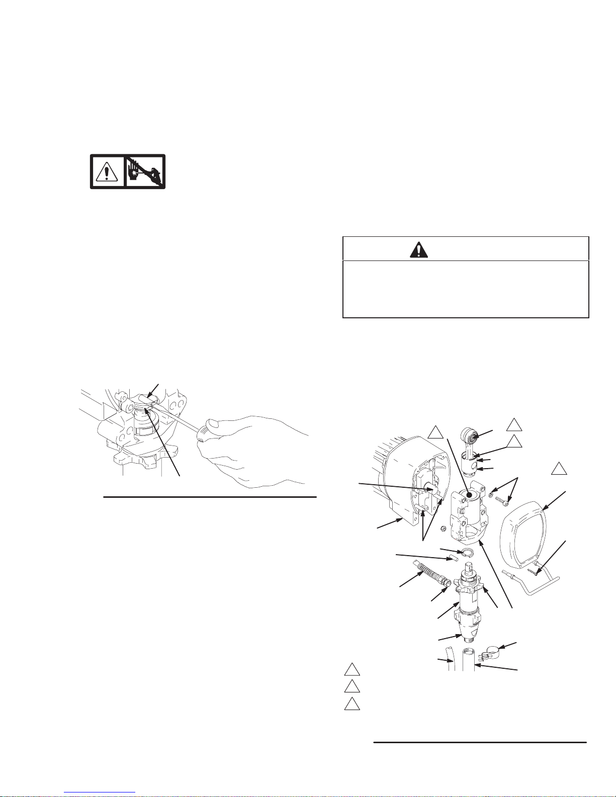
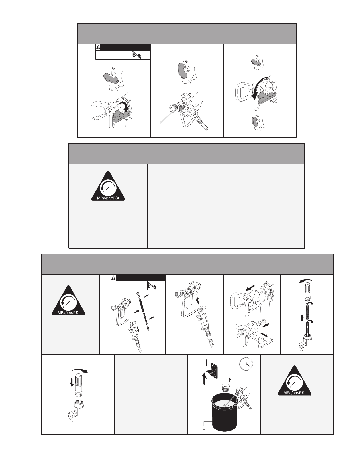
Bearing Housing and Connecting Rod
NOTE: The item numbers referenced are for the
Hi-Boy models. The Lo-Boy models models may have
different item numbers. Use the Hi-Boy item number
and part to find the corresponding Lo-Boy part and
item number.
Removal
1.
Relieve pressure; page 4.
2. Fig. 3. Remove screws (14) and front cover (23).
3. For Hi-Boy models; remove spring clip (32) and
drain hose (54). Unscrew suction tube (30) from
pump, hold wrench on pump intake valve (A) to
keep pump from loosening. For Lo-Boy models;
unscrew swivel union (30aa) from pump.
4. Disconnect pump outlet hose (33) from displace-
ment pump outlet nipple (62).
5. Fig. 2. Use screwdriver to push up retaining spring
(26) at top of pump. Push out pin (29).
2. Assemble connecting rod (22) and bearing housing
(21).
3. Clean mating surfaces of bearing and drive housings.
4. Align connecting rod with crank (B) and carefully
align locating pins (F) in drive housing (20) with
holes in bearing housing (21). Push bearing housing onto drive housing or tap into place with plastic
mallet.
CAUTION
DO NOT use bearing housing screws (13) to align
or seat bearing housing with drive housing. Align
these parts with locating pins (F), to avoid premature bearing wear.
5. Install screws (13) and lockwashers (12) on bearing housing. Torque evenly to note 3 value in Fig. 3.
29
Fig. 2
26
7675B
6. Fig. 3. Loosen retaining nut (34). Unscrew and
remove displacement pump (28).
7. Remove four screws (13) and lockwashers (12)
from bearing housing (21).
8. Pull connecting rod (22) and lightly tap lower rear
of bearing housing (21) with plastic mallet to
loosen from drive housing (20). Pull bearing housing and connecting rod assembly (22) off drive
housing.
9. Inspect crank (B) for excessive wear and replace
parts as needed.
Installation
1. Evenly lubricate inside of bronze bearing (C) in
bearing housing (21) with high-quality motor oil.
Liberally pack top roller bearing (E), lower bearing
(D) inside connecting rod assembly (22) with
bearing grease.
6. Refer to Displacement Pump, Installation, page 14.
2
C
1
E
2
D
22
12, 13
B
3
23
20
14
29
26
F
33
62
21
28
A
34
32
54
1
Oil
2
Pack with bearing grease 114819
3
GMax 3900: Torque to 200 in-lb (22.6 Nm)
GMax 5900: Torque to 25 ft-lb (34 Nm)
Fig. 3
Model 232610 shown
30
8697A
308868 7
Page 17
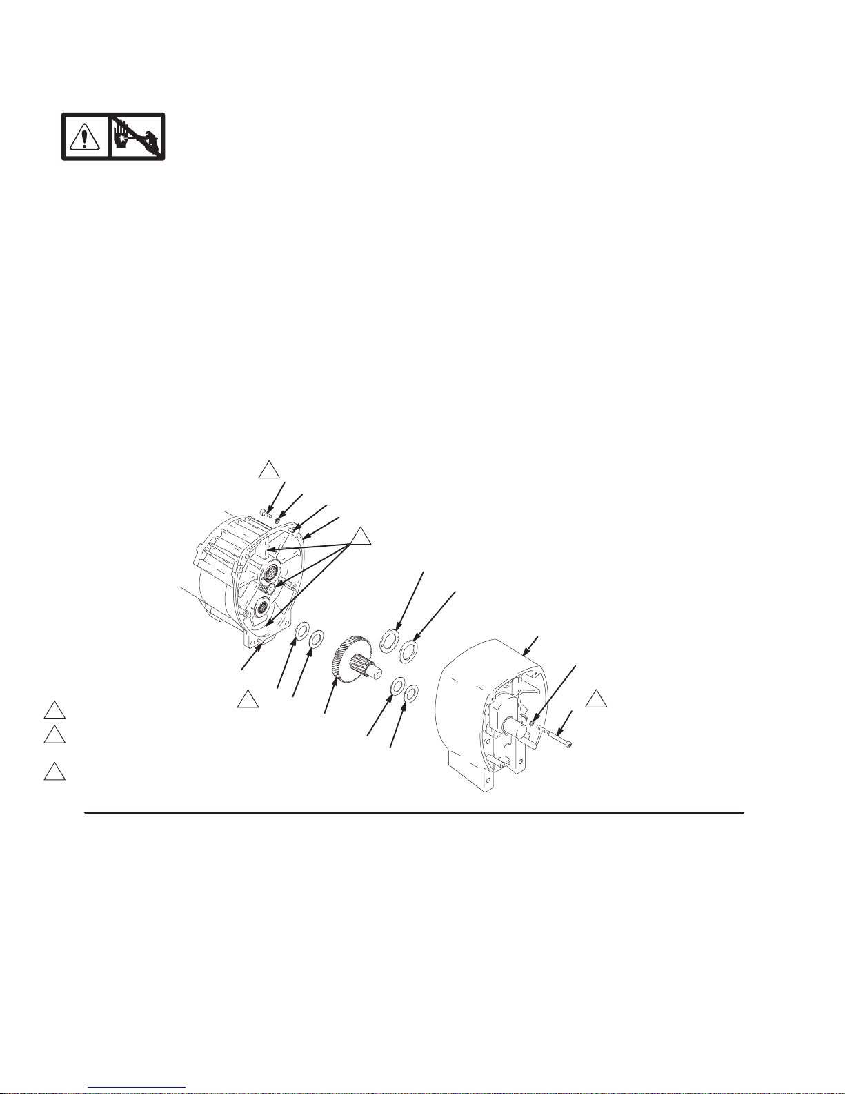
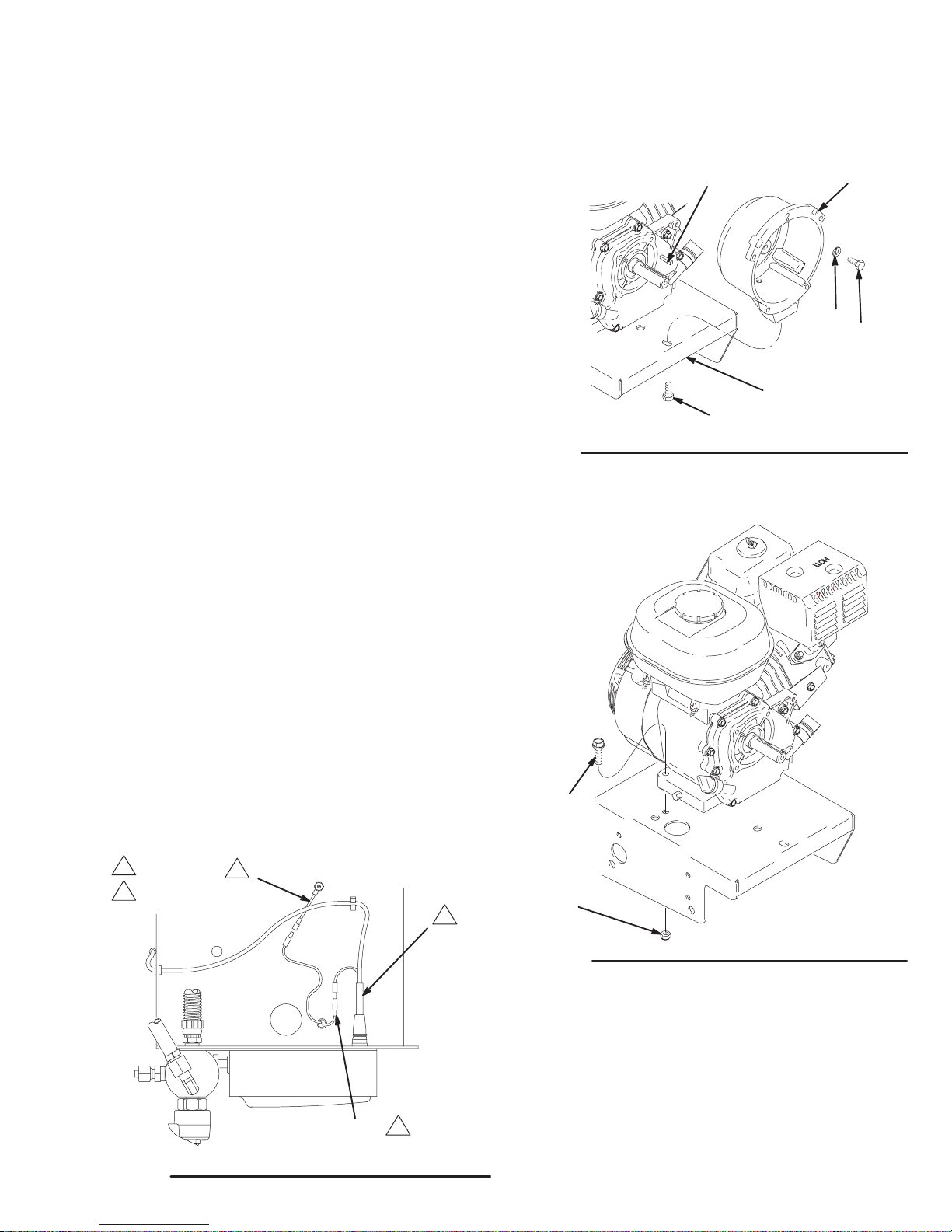
Drive Housing
Removal
1.
Relieve pressure; page 4.
2. Fig. 4. Remove bearing housing. Do 1. through 8.
of Bearing Housing and Connecting Rod procedure on page 7.
3. Remove two screws (81) and lockwashers (17).
4. Remove four screws (10) and lockwashers (17)
from pinion housing (19).
5. Lightly tap around drive housing (20) to loosen
drive housing. Pull drive housing straight off pinion
housing. Be prepared to support gear cluster (18),
which may also come out.
2
10
17
B
19
Installation
1. Liberally apply bearing grease (supplied with
replacement gear cluster) to gear cluster (18) and
to areas called out by note 3. Use full 0.62 pint
(0.29 liter) of grease for GMax 3900 and 0.68 pint
(0.32 liter) of grease for GMax 5900.
2. Place bronze colored washer (20g) on shaft protruding from large shaft of drive housing (20).
Place silver colored washer (20h) on pins on pinion
housing. Align gears and push new drive housing
straight onto pinion housing and locating pins (B).
3. Install four screws (10) and lockwashers (17) from
pinion housing (19).
4. Install two screws (81) and lockwashers (17).
5. Fig. 3. Install bearing housing. Do 1. through 6. of
Bearing Housing and Connecting Rod procedure on page 7.
B
1
GMax 3900 only
2
Torque to 125 in-lb – GMax 3900
Torque to 200 in-lb – GMax 5900
3
Apply remaining grease to these areas
Fig. 4
3
20h
20g
20
17
91
1
91
81
2
18
92
91
8698A
Page 18
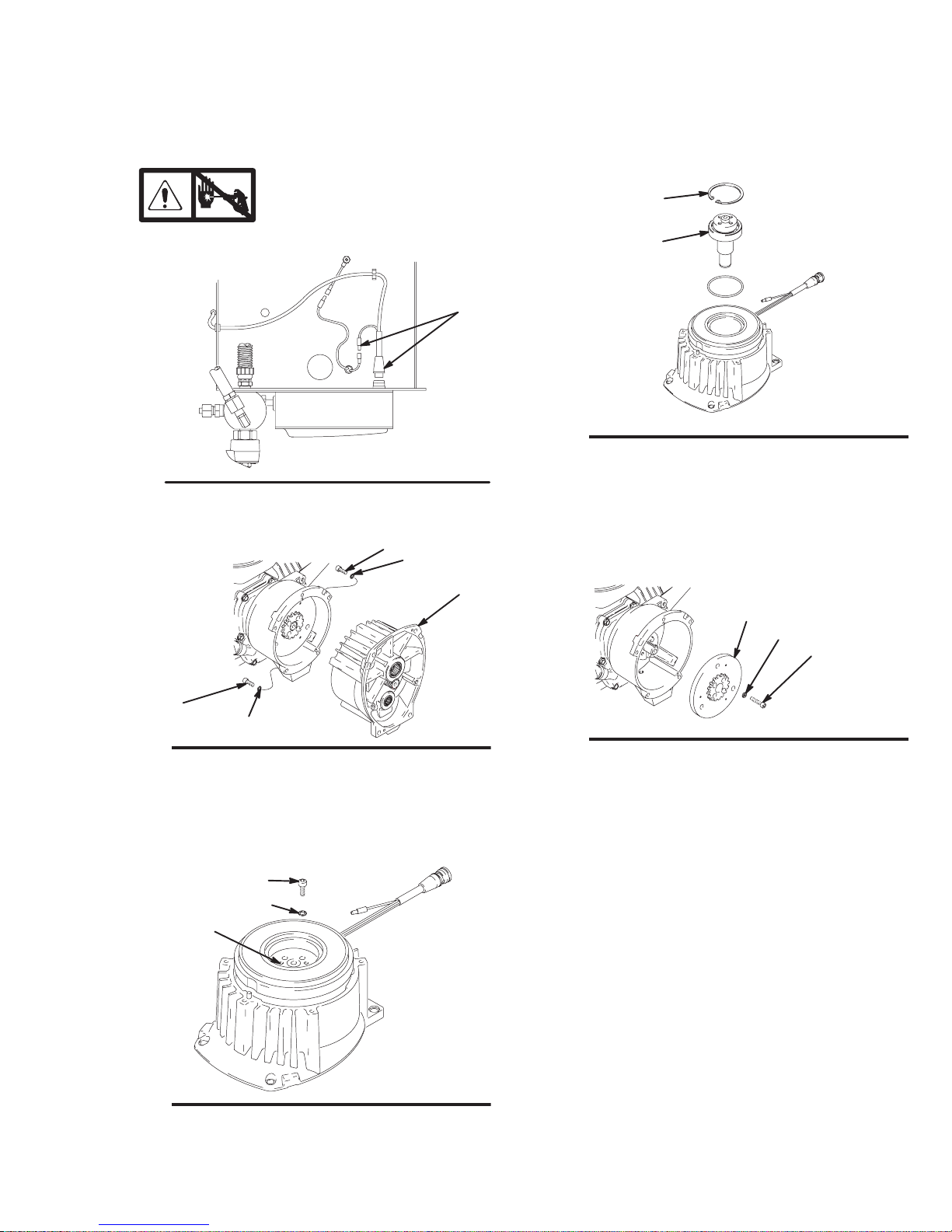
Pinion Assembly/Rotor/Field/Shaft/Clutch
Removal
If pinion assembly (19) is not removed from clutch
housing (5), do 1. through 4. Otherwise, start at 5.
6. Fig. 8. Remove retaining ring (Z).
7. Tap pinion shaft (A) out with plastic mallet.
1.
Relieve pressure; page 4.
2. Disconnect field cable (X) from pressure control.
X
Bottom View
Fig. 5
8699A
3. Fig. 6. Remove five screws (10) and lockwashers
(17) and pinion assembly (19).
10
17
19
Z
A
Fig. 8
8703A
8. Fig.9. Use an impact wrench or wedge something
between armature (4a) and clutch housing to hold
engine shaft during removal.
9. Remove four screws (16) and lockwashers (17).
10. Remove armature (4a).
4a
16
17
10
Fig. 6
17
8700A
4. Fig. 7. Place pinion assembly (19) on bench with
rotor side up.
5. Remove four screws (72) and lockwashers (17).
Install two screws in threaded holes (E) in rotor.
Alternately tighten screws until rotor comes off.
72
17
E
Fig. 7
8701A
Fig. 9
8704A
308868 9
Page 19
Pinion Assembly/Rotor/Field/Shaft/Clutch
Installation
1. Fig. 10. Lay two stacks of two dimes on smooth
6. Fig. 8. Tap pinion shaft (A) in with plastic mallet.
bench surface.
2. Lay armature (4a) on two stacks of dimes.
7. Install retaining ring (Z) with beveled side facing
field (Y).
3. Press center of clutch down on bench surface.
8. Fig. 7. Place pinion assembly on bench with rotor
4a
0.12 ±.01 in. (3.0 ±.25 mm)
side up.
9. Apply locktite to screws. Install four screws (16)
and lockwashers (17). Alternately torque screws
to 125 in-lb until rotor is secure. Use threaded
Fig. 10
4. Install armature (4a) on engine drive shaft.
8705A
holes to hold rotor.
10. Fig. 6. Install pinion assembly (19) with five screws
(10) and lockwashers (17).
5. Install four screws (16) and lockwashers (17) with
torque of 125 in-lb.
11. Fig. 5. Connect field cable (X) to pressure control.
Clamp
Removal
1. Fig. 11. Loosen two screws (16) on clamp (8),
2. Push screwdriver into slot in clamp (8) and remove
clamp.
Installation
1. Fig. 11. Install engine shaft key (7).
2. Tap clamp (8) on engine shaft (A) with plastic
mallet.
3. Press clamp (8) onto engine shaft (A). Maintain
dimension shown note 2 in Fig. 11.
Check dimension: Place rigid, straight steel bar (B)
across face of clutch housing (5). Use accurate
measuring device to measure distance between
bar and face of clamp. Adjust clamp as necessary.
Torque two screws (16) to 125 ±10 in-lb (14 ±1.1
Nm).
1
Face of clutch housing
1.550 ±.010 in. (39.37 ±.25 mm); GMax 3900
2
1.812 ±.010 in. (46.02 ±.25 mm); GMax 5900
3
T orque to 125 ±.10 in-lb (14 ±1.1 Nm)
1
5
7
B
Fig. 11
A
16
2
8
3
03483
30886810
Page 20
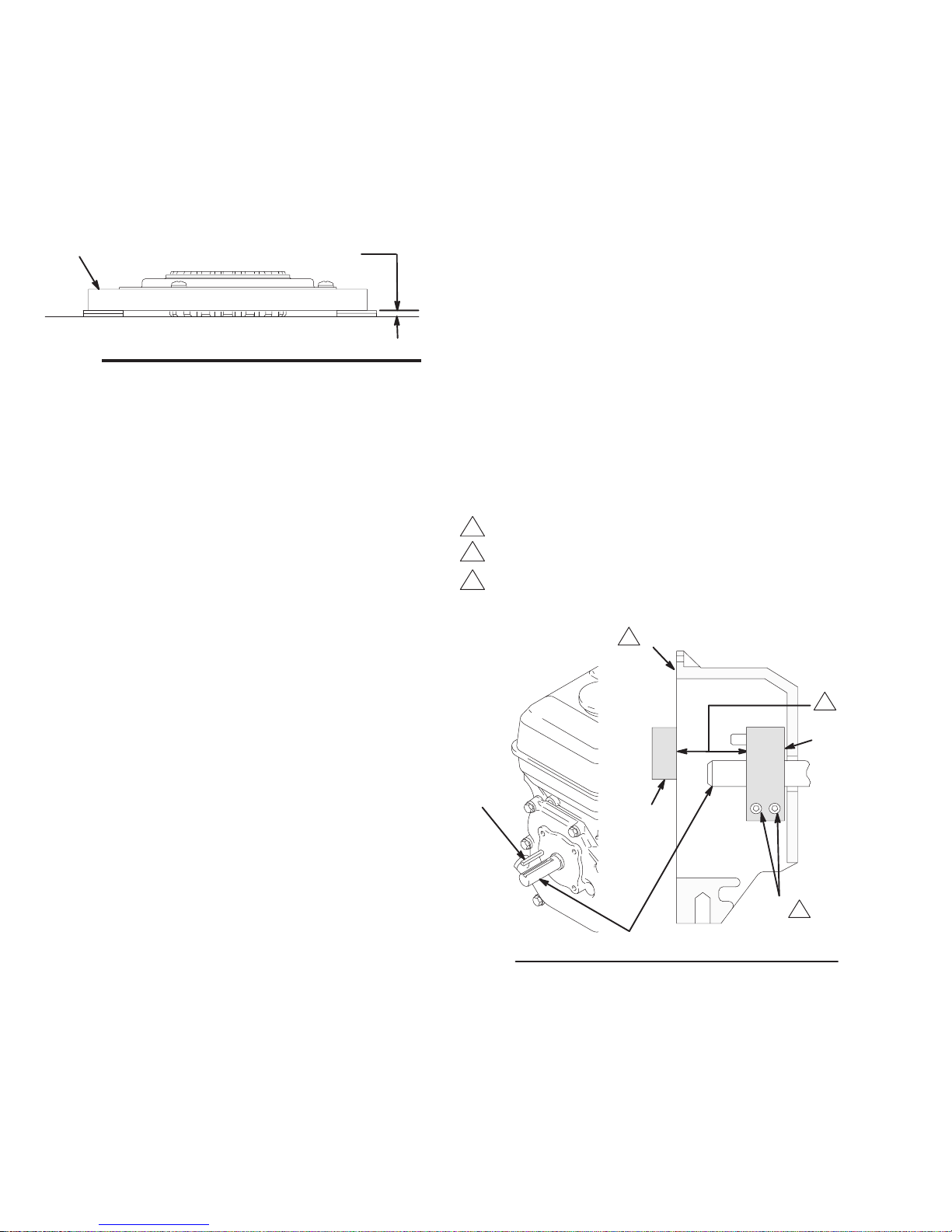
Clutch Housing
Removal
1. Fig. 12. Remove four capscrews (75) and lockwashers (77) which hold clutch housing (5) to
engine.
2. Remove screw (15) from under mounting plate (D).
3. Remove engine key (7).
4. Pull off clutch housing (5).
Installation
1. Fig. 12. Push on clutch housing (5).
2. Install four capscrews (75) and lockwashers (77)
and secure clutch housing (5) to engine. Torque to
200 in-lb (22.6 Nm).
3. Install capscrew (15) from beneath mounting
plate (D). Torque to 26 ft-lb (35.2 Nm).
Engine
Fig. 12
7
D
15
5
77
75
8708A
Removal
1. Remove Pinion Assembly/Rotor/Field/Pinion/
Clutch, Clamp and Clutch Housing, as in-
structed on pages 7, 9 and 10.
2. Fig. 13. Disconnect all necessary wiring.
3. Fig. 14. Remove two locknuts (71) and screws
(70) from base of engine.
4. Lift engine carefully and place on work bench.
NOTE: All service to the engine must be performed by
an authorized HONDA dealer.
1
T o the field
2
T o the engine
2
Green
1
70
71
Fig. 14
Installation
1. Lift engine carefully and place on cart.
8710A
Fig. 13
GMax 5900 only
Black
2. Fig. 14. Install two screws (70) in base of engine
and secure with locknuts (71). Torque to 200 in-lb
(22.6 Nm).
3. Fig. 13. Connect all necessary wiring.
2
8709A
4. Install Pinion Assembly/Rotor/Field/Pinion/
Clutch, Clamp and Clutch Housing, as
instructed on pages 8, 9 and 10.
308868 11
Page 21
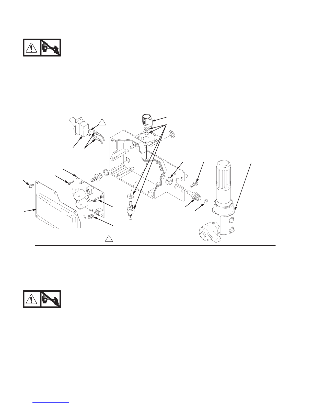
On/Off Switch
Removal
1.
2. Fig. 15. Remove five screws (307) and
cover (322).
3. Disconnect two wires (A) from ON/OFF
switch (309).
4. Press in on two retaining tabs on each side of
ON/OFF switch (309) and remove switch.
307
303
Relieve pressure; page 4.
A309
302
Installation
1. Install new ON/OFF switch (309) so tabs of switch
snap into place on inside of pressure control
housing.
2. Connect two wires (A) to ON/OFF switch.
3. Install pressure control cover (322) with five
screws (307).
313
310
315 319
318a
322
Fig. 15
Pressure Control
Removal
1.
2. Fig. 15. Remove five screws (307) and
cover (322).
3. Fig. 22. Disconnect at control board (302):
Four clutch leads: two violet and two black.
Lead (D) from potentiometer.
Lead (E) from transducer.
Relieve pressure; page 4.
D
E
Locate switch terminals as shown
318z
Control Board
Installation
When installing replacement control board, follow
instructions with control board to set model type.
1. Fig. 15. Install green ground wire and control
board (302) with five screws (303).
2. Fig. 22. Connect to control board (302):
Two red leads (A) to ON/OFF switch (309).
Lead (E) to transducer.
318aa
Two red leads (A) to ON/OFF switch (309).
4. Fig. 15. Remove five screws (303), green ground
wire and control board (302).
30886812
Lead (D) to potentiometer.
Four clutch leads: two violet and two black.
3. Fig. 15. Install cover (322) with five screws (307).
Page 22
Pressure Control Transducer
Removal
1.
2. Fig. 15. Remove five screws (307) and
cover (322).
3. Disconnect lead (E) from control board (302).
4. Remove three screws (319) and fluid filter (318)
from control plate (301). Carefully pull transducer
connector through rubber grommet (315).
Relieve pressure; page 4.
Pressure Adjust Potentiometer
Removal
1.
2. Fig. 15. Remove five screws (307) and
cover (322).
3. Disconnect lead (D) from control board (302).
4. Loosen set screws on potentiometer knob (313)
and remove knob, shaft nut, lockwasher (310) and
pressure adjust potentiometer (310).
5. Remove seal (311) from potentiometer (310).
Relieve pressure; page 4.
5. Remove pressure control transducer (318z) and
packing o-ring (318aa) from filter housing (318a).
Installation
1. Fig. 15. Install packing o-ring (318aa) and pressure control transducer (318z) in filter
housing (318a). Torque to 30–35 ft-lb.
2. Carefully feed transducer connector through
rubber grommet (315). Install fluid filter (318) on
control plate (301) with three screws (319).
3. Connect lead (E) to motor control board (302).
4. Install cover (322) with five screws (307).
Installation
1. Install seal (311) on potentiometer (310).
2. Fig. 15. Install pressure adjust potentiometer
(310), shaft nut, lockwasher (310) and potentiometer knob (313).
a. Turn potentiometer shaft (310) clockwise to
internal stop. Assemble potentiometer knob
(313) to strike pin on plate (312) and have
bottom of knob clear plate by .040 to .060 in.
b. After adjustment of step a., tighten both set
screws in knob 1/4 to 3/8 turn after contact
with shaft.
3. Connect lead (D) to control board (302).
4. Install cover (322) with five screws (307).
Control Board Diagnostics
1. Fig. 15. Remove five screws (307) and
cover (322).
2. Start sprayer.
LED
BLINKS
Two times
repeatedly
Three
times repeatedly
Four times
repeatedly
Five times
repeatedly
SPRAYER OPERATION INDICATES WHAT TO DO
Sprayer shuts down and LED continues to blink two times repeatedly
Sprayer shuts down and LED continues to blink three times repeatedly
Sprayer shuts down and LED continues to blink four times repeatedly
Sprayer shuts down and LED continues to blink five times repeatedly
3. Turn ON/OFF switch ON.
4. Observe LED operation and reference following
table:
Run away pressure.
Pressure greater than
4500 psi (310 bar, 31
MPa).
Pressure transducer is
faulty or missing
Generator voltage is
low
High clutch current 1. Check clutch 5-pin bulkhead con-
1. Check pressure transducer connection at control board
2. Replace pressure transducer
3. Replace control board
1. Check pressure transducer connection at control board
2. Replace pressure transducer
3. Replace control board
1. Increase engine throttle
2. Check wiring connections
3. Service Honda engine alternator
nector. Clean contacts.
2. Measure 1.2 0.2Ω
(GMax3900); 1.7 0.2Ω (GMax
5900) across clutch field at 70F
3. Replace clutch field assembly
Six times
repeatedly
Sprayer shuts down and LED continues to blink six times repeatedly
High clutch temperature Replace clutch armature and rotor
308868 13
Page 23

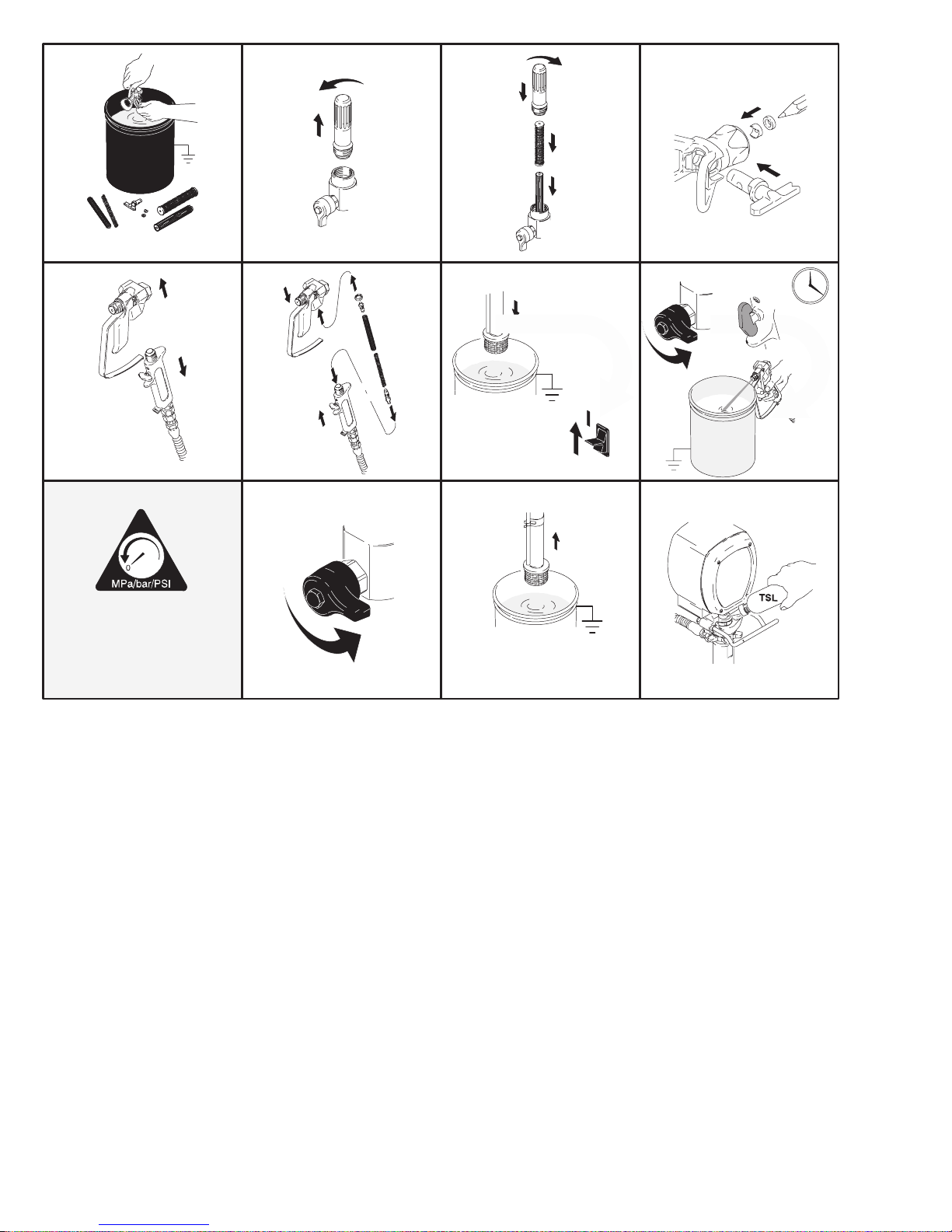
Removal
Displacement Pump
1. Flush pump.
2.
3. Fig. 16. Cycle pump with piston rod (222) in its
lowest position.
4. Fig. 16. Remove suction tube (30) and hose (33).
33
Fig. 16
Relieve pressure; page 4.
222
30
7672B
Repair
5. Fig. 17. Use screwdriver: push retaining spring up
and push out pin (29).
29
Fig. 17
6. Fig. 18. Loosen locknut by hitting firmly with a
20 oz (maximum) hammer. Unscrew pump.
Fig. 18
7675B
7673B
See manual 308798 for pump repair instructions.
Installation
WARNING
If pin works loose, parts could break off due to
force of pumping action. Parts could project
through the air and result in serious injury or property damage. Make sure pin and retaining spring
are properly installed.
CAUTION
If the pump locknut loosens during operation, the
threads of the bearing housing will be damaged.
Make sure locknut is properly tightened.
1. Fig. 19. Pull piston rod out 1.5 in. Screw in pump
until holes in bearing cross link and piston rod
align.
2. Fig. 17. Push pin (29) into hole. And push retaining
spring into groove all the way around connecting
rod.
Fig. 20. Screw jam nut down onto pump until stops.
Screw pump up into bearing housing until it is stopped
by jam nut. Back off pump and jam nut to align pump
outlet to back. Tighten jam nut by hand, then tap 1/8 to
1/4 turn with a 20 oz (maximum) hammer to approximately 75" 5 ft–lb (102 Nm).
Fig. 20
Fig. 21. Fill packing nut with Graco TSL until fluid flows
onto the top of seal.
7673B
1.5 in.
Fig. 19
30886814
7676B
Fig. 21
7677B
Page 24

Parts Drawing – GMax 3900 and GMax 5900 Hi-Boy Sprayers
Models 232610 and 232620
Ref 11
40
45
3
2
11
DETAIL A
49
35
47
DETAIL A
37
38
51
Ref 35
56
1
1
Label
2
See page 17 for the parts.
3
See manual 308798
for the parts.
4
See page 21 for the parts.
5
Used on GMax 5900, Model 232620
Used on GMax 3900, Model 232610
6
10
72
17
4b
6
10
17
5
7
8
91
17
18
16
17
92
4a
19
55
2
20h
91
33
68
26
29
2
20g
62
54
78
8699A
Bottom View
87
5
2
2
20
17
81
61
22
12
13
23
21
34
67
28
3
14
70
61
71
41
44
5
42
43
15
77
51
50
75
80
17
16
90
30
31
71
33(Ref)
53
4
53
88
89
54(Ref)
8712A
308868 15
Page 25

Parts List – GMax 3900 and GMax 5900 Hi-Boy Sprayers
Models 232610 and 232620
Ref
No. Part No. Description Qty
1 ENGINE
108879 GMax 3900, Model 232610 1
114530 GMax 5900, Model 232620 1
2 1 13084 RIVET , blind 2
3 192014 PLATE, indicator 1
4 CLUTCH ASSEMBL Y ,
includes 4a, 4b, 16, 17, 80
241 109 GMax 3900, Model 232610 1
241 113 GMax 5900, Model 232620 1
4a .ARMA TURE, clutch, 4 in., 1
GMax 3900, Model 232610
.ARMA TURE, clutch, 5 in., 1
GMax 5900, Model 232620
4b .ROTOR
4 in., GMax 3900, Model 232610 1
5 in., GMax 5900, Model 232620 1
5 CLUTCH HOUSING
193540 GMax 3900, Model 232610 1
193531 GMax 5900, Model 232620 1
7 183401 KEY , parallel 1
8 193680 CLAMP 1
10 CAPSCREW , socket head, 1/4–20 x 3/4 in.
100644 GMax 3900, Model 232610 9
101864 GMax 5900, Model 232620 4
11 239998 CART HANDLE & HOSE RACK 1
12 106115 LOCKWASHER, spring, 3/8 in. 4
13 CAPSCREW , socket head,
107210 GMax 3900, Model 232610; 3/8–16 x 1.5 in. 4
114666 GMax 5900, Model 232620; 3/8–16 x 2.25 in.4
14 114418 SCREW, self–tap, fil hd, 8–32 x 1 in. 4
15 113802 SCREW, flange, hex hd, 3/8–16 x 5/8 in. 1
16 108803 CAPSCREW, sch, 1/4–2 x 1 in. 6
17 LOCKWASHER, spring, 1/4 in.
105510 GMax 3900, Model 232610 21
105510 GMax 5900, Model 232620 11
18 GEAR COMBINATION
241439 GMax 3900, Model 232610 1
241440 GMax 5900, Model 232620 1
19 PINION ASSEMBL Y; Parts, page 17
241 108 GMax 3900, Model 232610 1
241 112 GMax 5900, Model 232620 1
20 DRIVE HOUSING; Parts, page 17
241007 GMax 3900, Model 232610 1
24101 1 GMax 5900, Model 232620 1
21 BEARING HOUSING
240523 GMax 3900, Model 232610 1
241015 GMax 5900, Model 232620 1
22 CONNECTING ROD
241008 GMax 3900, Model 232610 1
241012 GMax 5900, Model 232620 1
23 COVER, HOUSING, DRIVE
179899 GMax 3900, Model 232610 1
241308 GMax 5900, Model 232620 1
26 SPRING, retaining
176817 GMax 3900, Model 232610 1
183169 GMax 5900, Model 232620 1
28 DISPLACEMENT PUMP
Parts, manual 308798
239923 GMax 3900, Model 232610 1
240291 GMax 5900, Model 232620 1
29 PIN, straight
176818 GMax 3900, Model 232610 1
183210 GMax 5900, Model 232620 1
30 TUBE, intake
192641 GMax 3900, Model 232610 1
193097 GMax 5900, Model 232620 1
Ref
No. Part No. Description Qty
31 STRAINER
32 194194 CLIP , spring 1
33 240795 HOSE, coupled 1
34 NUT , retaining
35 CART FRAME
37 183350 WASHER, plain 2
38 110243 RING, retaining 2
39 108795 SCREW, mch, pn hd, 10–32 x 5/16 in. 4
40 SLEEVE
41 WHEEL, semi–pneumatic
42 101242 RING, retaining 2
43 104811 HUBCAP 2
44 154636 WASHER, GMax 5900, Model 232620 only 2
45 112827 BUTTON, snap 2
47 237686 GROUNDING CLAMP & WIRE 1
49 112798 SCREW, hex washer hd,, No. 8 x 3/8 in 1.
50 193700 PLUG, tubing; GMax 3900, Model 232610 2
51 109032 SCREW, mch, pn hd; 6
53 164672 ADAPTER 2
54 194178 HOSE, drain 1
55 194125 LABEL, danger 1
56 194126 LABEL, warning 1
61 114678 BUSHING, strain relief 1
62 NIPPLE, 3/8–18 npsm(m) x 1/4 npt(m)
67 192719 HANGER, pail 1
68 112746 LOCKNUT , 5/16–18 2
70 110837 SCREW, flng, hex hd, 5/16–18 x 1–1/2 in. 2
71 110838 LOCKNUT , heavy hex, 5/16–18 6
72 101682 SCREW, cap, sch 4
73 SCREW , cap, sch 4
75 109031 SCREW, cap, sch 4
76 101864 SCREW, cap, sch 4
77 WASHER, lock, spring
78 114687 CLIP , retainer 1
80 HUB, armature 1
81 107218 SCREW 2
82 206994 THROAT SEAL LIQUID; not shown 1
87 240997 CONDUCTOR, ground 1
88 110249 ADAPTER, male elbow, 90 1
89 240131 PLUG, packless 1
90 194195 DEFLECTOR 1
91 WASHER
92 114699 WASHER 1
181072 GMax 3900, Model, 232610 1
189920 GMax 5900, Model, 232620 1
192723 GMax 3900, Model 232610 1
193031 GMax 5900, Model 232620 1
240696 GMax 3900, Model 232610 1
240726 GMax 5900, Model 232620 1
192027 GMax 3900, Model 232610 2
191084 GMax 5900, Model 232620 2
106062 GMax 3900, Model 232610 2
17981 1 GMax 5900, Model 232620 2
193682 CAP , end; GMax 5900, Model 232620 2
GMax 3900, Model 232610 only
183461 GMax 3900, Model 232610 1
162485 GMax 5900, Model 232620 1
109031 GMax 3900, Model 232610 4
108842 GMax 5900, Model 232620 4
104008 GMax 3900, Model 232610 4
100214 GMax 5900, Model 232620 4
114672 GMax 3900, Model 232610 3
114672 GMax 5900, Model 232620 2
Danger & Warning labels, tags, and cards are free.
30886816
Page 26

Parts List & Drawing – Pinion Assembly
Ref No. 19 and 20
Ref No. 19: Pinion Housing Assembly 241108 for
GMax 3900; Pinion Housing Assembly 241112 for
GMax 5900
Ref
No. Part No. Description Qty
19 PINION HOUSING 1
19b 105489 PIN 2
19d* PINION SHAFT
241110 GMax 3900, Model 232610 1
241114 GMax 5900, Model 232620 1
19e* RETAINING RING, large
1 13094 GMax 3900, Model 232610 1
1 12770 GMax 5900, Model 232620 1
*Must be ordered separately ..
19e
19d
19b
10 (Ref)
17 (Ref)
Ref No. 20: Drive Housing Assembly 241007 for
GMax 3900; Drive Housing Assembly 241011 for
GMax 5900
Ref
No. Part No. Description Qty
20 DRIVE HOUSING ASSEMBL Y
20g* W ASHER
194173 GMax 3900, Model 232610 1
107089 GMax 5900, Model 232620 1
20h* WASHER
194172 GMax 3900, Model 232610 1
194411 GMax 5900, Model 232620 1
*Must be ordered separately ..
19
20h
20g
91 (Ref)
1
18 (Ref)
1
Only used on GMax 3900, Models 232610 and 232612
91 (Ref)
92 (Ref)
20
17 (Ref)
81 (Ref)
8715A
308868 17
Page 27

Parts Drawing – GMax 3900 and GMax 5900 Lo-Boy Sprayers
Models 232612 and 232622
Ref 11
40
45
3
2
11
DETAIL A
49
DETAIL A
37
38
51
Ref 35
56
70
1
Label
2
See page 17 for the parts.
3
See manual 308798
for the parts.
4
See page 21 for the parts.
5
Used on GMax 5900, Model 232622 only
6
Used on GMax 3900, Model 232612 only
5
76
10
6
72
17
4b
17
5
77
6
2
19
20h
2
20g
2
2
20
91
87
5
17
Bottom View
81
22
78
8699A
61
12
13
1
91
6
18
21
23
92
10
17
5
55
26
29
7
8
17
16
33
62
34
14
35
47
71
41
44
5
42
43
30886818
15
51
77
75
6
50
80
17
4
30d
30b (Ref)
16
4a
30aa
30a
30b
30e
30f
30ae
30ad
53
89
30c
30g
30ab
28
3
30
8713A
Page 28

Parts List – GMax 3900 and GMax 5900 Lo–Boy Sprayers
Models 232612 and 232622
Ref
No. Part No. Description Qty
1 ENGINE
108879 GMax 3900, Model 232612 1
114530 GMax 5900, Model 232622 1
2 1 13084 RIVET , blind 2
3 192014 PLATE, indicator 1
4 CLUTCH ASSEMBL Y ,
includes 4a, 4b, 16, 17, 80
241 109 GMax 3900, Model 232612 1
241 113 GMax 5900, Model 232622 1
4a .ARMA TURE, clutch, 4 in., 1
GMax 3900, Model 232612
.ARMA TURE, clutch, 5 in., 1
GMax 5900, Model 232622
4b .ROTOR
4 in., GMax 3900, Model 232612 1
5 in., GMax 5900, Model 232622 1
5 CLUTCH HOUSING
193540 GMax 3900, Model 232612 1
193531 GMax 5900, Model 232622 1
7 183401 KEY , parallel 1
8 193680 COLLAR, shaft 1
10 CAPSCREW , socket head, 1/4–20 x 3/4 in.
100644 GMax 3900, Model 232612 9
101864 GMax 5900, Model 232622 4
11 239998 CART HANDLE & HOSE RACK 1
12 106115 LOCKWASHER, spring, 3/8 in. 4
13 CAPSCREW , socket head,
107210 GMax 3900, Model 232612; 3/8–16 x 1.5 in. 4
114666 GMax 5900, Model 232622; 3/8–16 x 2.25 in.4
14 114418 SCREW, self–tap, fil hd, 8–32 x 1 in. 4
15 113802 SCREW, flange, hex hd,, 3/8–16 x 5/8 in. 1
16 108803 CAPSCREW, sch, 1/4–2 x 1 in. 6
17 LOCKWASHER, spring, 1/4 in.
105510 GMax 3900, Model 232612 21
105510 GMax 5900, Model 232622 11
18 GEAR COMBINATION
241439 GMax 3900, Model 232612 1
241440 GMax 5900, Model 232622 1
19 PINION ASSEMBL Y; Parts, page 17
241 108 GMax 3900, Model 232612 1
241 112 GMax 5900, Model 232622 1
20 DRIVE HOUSING
241007 GMax 3900, Model 232612 1
24101 1 GMax 5900, Model 232622 1
21 BEARING HOUSING
240014 GMax 3900, Model 232612 1
240724 GMax 5900, Model 232622 1
22 CONNECTING ROD
241008 GMax 3900, Model 232612 1
241012 GMax 5900, Model 232622 1
23 COVER, HOUSING, DRIVE
179899 GMax 3900, Model 232612 1
241308 GMax 5900, Model 232622 1
26 SPRING, retaining
176817 GMax 3900, Model 232612 1
183169 GMax 5900, Model 232622 1
28 DISPLACEMENT PUMP , Manual 308798
239923 GMax 3900, Model 232612 1
240291 GMax 5900, Model 232622 1
29 PIN, straight
176818 GMax 3900, Model 232612 1
183210 GMax 5900, Model 232622 1
30 241287 ASSEMBLY, tube, suction
30a 241 124 .TUBE, suction, 5 gallon (20 liter) 1
30aa 240513 ..SWIVEL, tube, inlet 1
30ab 176450 ..GUARD, hose 1
Ref
No. Part No. Description Qty
30ac 194306 ..HOSE, fluid 1
30ad 101818 ..CLAMP , hose 2
30ae 170957 ..TUBE, suction 1
30b 194180 .HOSE, drain 1
30c 194191 .CLIP , spring 1
30d 162453 .NIPPLE 1
30e 194195 .DEFLECTOR 1
30f 187147 .STRAINER 1
30g 144958 .STRAP, tie 1
33 240795 HOSE, coupled 1
34 NUT , retaining
35 CART FRAME
37 183350 WASHER, plain 2
38 110243 RING, retaining 2
39 108795 SCREW, mch, pn hd, 10–32 x 5/16 in. 6
40 SLEEVE
41 WHEEL, semi-pneumatic
42 101242 RING, retaining 2
43 104811 HUBCAP 2
44 154636 WASHER, GMax 5900, Model 232622 only 2
45 112827 BUTTON, snap 2
46 108068 PIN, spring, straight, 3/16 x 1–1/4 in. 2
47 237686 GROUNDING CLAMP & WIRE 1
49 112798 SCREW, hex washer hd, No. 8 x 3/8 in 1.
50 193700 PLUG, tubing; GMax 3900, Model 232612 2
51 109032 SCREW, GMax 3900, Model 232612 only 6
52 100020 WASHER, GMax 3900, Model 232612 only 4
53 164672 ADAPTER 2
55 194125 LABEL, danger 1
56 194126 LABEL, warning 1
61 114678 BUSHING, strain relief 1
62 NIPPLE, 3/8–18 npsm(m) x 1/4 npt(m)
70 110837 SCREW, flng, hex hd, 5/16–18 x 1–1/2 in. 2
71 110838 LOCKNUT , heavy hex, 5/16–18 6
72 101682 SCREW, cap, sch 4
73 SCREW , cap, sch 4
75 109031 SCREW, cap, sch 4
77 WASHER, lock, spring
78 114687 CLIP , retainer 1
80 HUB, armature 1
81 107218 SCREW 2
82 206994 THROAT SEAL LIQUID; not shown 1
87 240997 CONDUCTOR, ground 1
89 240131 PLUG, packless 1
89 Washer
92 114699 WASHER 1
192723 GMax 3900, Model 232612 1
193031 GMax 5900, Model 232622 1
240728 GMax 3900, Model 232612 1
240727 GMax 5900, Model 232622 1
192027 GMax 3900, Model 232612 2
191084 GMax 5900, Model 232622 2
106062 GMax 3900, Model 232612 2
17981 1 GMax 5900, Model 232622 2
193682 CAP , end; GMax 5900, Model 232622 2
183461 GMax 3900, Model 232612 1
162485 GMax 5900, Model 232622 1
109031 GMax 3900, Model 232612 4
108842 GMax 5900, Model 232622 4
104008 GMax 3900, Model 232612 4
100214 GMax 5900, Model 232622 4
114672 GMax 3900, Model 232612 3
114699 GMax 5900, Model 232622 2
Danger & Warning labels, tags, and cards are free.
308868 19
Page 29

Parts List & Drawing – Complete Sprayers
Models 232611, 232613, 232621, 232623
GMax 3900 and GMax 5900 Airless Paint Sprayers
Includes items 201 to 204
Ref
No. Part No. Description Qty
201 232611 GM3900 Hi-Boy Sprayer 1
See parts list on page 15
232621 GM5900 Hi-Boy Sprayer 1
See parts list on page 15
232613 GM3900 Lo-Boy Sprayer 1
See parts list on page 19
232623 GM5900 Lo-Boy Sprayer 1
See parts list on page 19
202 240794 HOSE, grounded, nylon; 1/4 in. ID; 1
cpld 1/4 npsm(fbe); 50 foot (15 m);
spring guards both ends
3300 psi (227 bar, 27.7 MPa)
203 238358 HOSE, grounded, nylon; 3/16 in. ID;
cpld 1/4 npsm(m) x 1/4 npsm(f) swivel;
3 foot (0.9 m); spring guards both ends 1
204 220955 CONTRACTOR SPRAY GUN
Includes RAC IV
and 517–size SwitchTip
See 307614 for parts 1
DripLess Tip Guard
Accessories
202
204
203
0160
DANGER LABELS
An English language DANGER label is on your
sprayer. If you have painters who do not read English, order one of the following labels to apply to
your sprayer. The drawing shows the best placement of these labels for good visibility.
Order the labels from your Graco distributor.
Apply other
language here
French 185956
Spanish 185961
German 186041
Greek 186045
Korean 186049
English 194125
Displacement Pump Repair Kits
Packing repair kits.
GMax 3900 239928
GMax 5900 240248
03497A
30886820
Page 30

Parts Drawing – Sprayer
GMax 3900 and 5900 Sprayers
Models 232610 through 232613 and 232619
Models 232620 through 232623 and 232629
309
308
320
314
313
310
312
321
301
305
304
306
302
303
315
307
318f
304
318e
319
318d
318b
318c
318z
307
322
305
311
310
318aa
318a
318g
318h
318m
318n
318l
318j
318k
8716A
308868 21
Page 31

Parts List – Sprayer
Models 232610 through 232613 and 232619; 232620 through 232623 and 232629
REF
NO. PART NO. DESCRIPTION QTY
301 193653 PLATE, control 1
302 241093 BOARD, PC 1
303 111839 SCREW, mch pan, 6–32 x 1/2 in. 5
304 240776 HARNESS, wiring. 1
305 193497 GASKET, control 2
306 193652 HOUSING, control box 1
307 114631 SCREW, mch, pan hd 10
308 193052 PLATE, instruction 1
309 114277 SWITCH, rocker , (spst) 1
310 241443 POTENTIOMETER, pressure control 1
311 193657 GASKET, potentiometer 1
312 193654 PLATE, instruction 1
313 114273 KNOB, potentiometer 1
314 193072 LABEL, control 1
315 114629 GROMMET, transducer 1
318 240777 FILTER, fluid 1
318a 193651 HOUSING, filter 1
318b 104361 O-RING 1
318c 186075 SUPPORT, filter 1
318d 167025 STRAINER, mesh, 60 1
REF
NO. PART NO. DESCRIPTION QTY
318e 171941 SPRING, compression 1
318f 192706 BOWL, filter 1
318g 193710* SEAL, valve 1
318h 193709* SEAT, valve 1
318j 194102* HANDLE, valve 1
318k 1 14688* NUT, cap, hex hd 1
318l 114708* SPRING, compression 1
318m 114797* GASKET 1
318n 240914* VALVE 1
318z 240314 TRANSDUCER, pressure control 1
318aa111457 O-RING 1
319 110997 SCREW, flange, hex 3
320 114532 TIE, wire, twist 1
189246 LABEL, warning 1
321
322 241444 COVER, pressure control 1
* Drain valve replacement kit 241276 available; includes
318g through 318n
Replacement warning labels may be ordered free of charge
includes 318aa
309
(Ref)
304
(Ref)
Fig. 22
Green
Black
Red
Red (+)
Violet
Wiring Diagram
310
D
E
A
318z
(Ref)
302
(Ref)
(Ref)
Potentiometer
Pressure
transducer
318aa
(Ref)
30886822
Page 32

Technical Data
PTFE
PTF
Honda GX120 Engine
Power Rating @ 3700 rpm
ANSI 4.0 Horsepower. . . . . . . . . . . . . . . . . . . . . . .
DIN 6270B/DIN 6271
NA 2.1 Kw – 2.8 Ps. . . . . . . . . . . . . . . . . . . . . .
NB 2.6 Kw – 3.6 Ps. . . . . . . . . . . . . . . . . . . . . .
Honda GX160 Engine
Power Rating @ 3700 rpm
ANSI 5.5 Horsepower. . . . . . . . . . . . . . . . . . . . . . .
DIN 6270B/DIN 6271
NA 2.9 Kw – 4.0 Ps. . . . . . . . . . . . . . . . . . . . . .
NB 3.6 Kw – 4.9 Ps. . . . . . . . . . . . . . . . . . . . . .
Maximum working pressure 3300 psi . . . . . . . . . . . . . . .
(227 bar, 22.7 MPa
Noise Level
Sound power 105 dBa. . . . . . . . . . . . . . . . . . . . . . . . .
per ISO 3744
Sound pressure 96 dBa. . . . . . . . . . . . . . . . . . . . . . . .
measured at 3.1 feet (1 m)
Cycles/gallon (liter)
GMax3900 182 (48). . . . . . . . . . . . . . . . . . . . . . . . . . .
GMax5900 93 (25). . . . . . . . . . . . . . . . . . . . . . . . . . . .
Maximum delivery rating
GMax3900 1.15 gpm (4.4 liter/min). . . . . . . . . . . . .
GMax5900 1.5 gpm (5.7 liter/min). . . . . . . . . . . . . . .
Maximum tip size
GMax3900 1 gun with 0. 034 in. tip. . . . . . . . . . . . .
2 guns with 0.024 in. tip
3 guns with 0. 017 in. tip
GMax5900 1 gun with 0. 041 in. tip. . . . . . . . . . . . .
2 guns with 0.028 in. tip
3 guns with 0. 022 in. tip
4 guns with 0. 019 in. tip
Inlet paint strainer 16 mesh (1190 micron). . . . . . . . . . .
stainless steel screen, reusable
Outlet paint filter 60 mesh (250 micron). . . . . . . . . . . . .
stainless steel screen, reusable
)
Pump inlet size 3/4 in. npt (m). . . . . . . . . . . . . . . . . . . . . .
Fluid outlet size 1/4 npsm from fluid filter. . . . . . . . . . . .
Wetted parts zinc-plated carbon steel,
Viton, Delrin, leather, aluminum, tungsten car-
bide,nickle-plated carbon steel, stainless steel,
chrome plating
NOTE: Delrin, , Viton are trademarks
. . . . . . . . . . . . . .
, Nylon, polyurethane, UHMW polyethylene,
Model 232610
Hi-Boy without hose or gun
Weight (dry, without packaging) 110 lb (49.9 kg). . . . .
Height 40 in. (101.6 cm). . . . . . . . . . . . . . . . . . . . . . . . . .
Length 37 in. (94 cm). . . . . . . . . . . . . . . . . . . . . . . . . . . . .
Width 22 in. (55.9 cm). . . . . . . . . . . . . . . . . . . . . . . . . . . .
Model 232620
Hi-Boy without hose or gun
Weight (dry, without packaging) 150 lb (68 kg). . . . . . .
Height 41 in. (104.1 cm). . . . . . . . . . . . . . . . . . . . . . . . . .
Length 39 in. (99.1 cm). . . . . . . . . . . . . . . . . . . . . . . . . . .
Width 22 in. (55.9 cm). . . . . . . . . . . . . . . . . . . . . . . . . . . .
Graco Phone Number
Dimensions
GMax 3900
Model 232612
Lo-Boy Cart without hose or gun
Weight (dry, without packaging) 110 lb (49.9 kg). . . . .
Height 40 in. (101.6 cm). . . . . . . . . . . . . . . . . . . . . . . . . .
Length 37 in. (94 cm). . . . . . . . . . . . . . . . . . . . . . . . . . . . .
Width 22 in. (55.9 cm). . . . . . . . . . . . . . . . . . . . . . . . . . . .
GMax 5900
Model 232622
Lo-Boy without hose or gun
Weight (dry, without packaging) 150 lb (68 kg). . . . . . .
Height 41 in. (104.1 cm). . . . . . . . . . . . . . . . . . . . . . . . . .
Length 39 in. (99.1 cm). . . . . . . . . . . . . . . . . . . . . . . . . . .
Width 22 in. (55.9 cm). . . . . . . . . . . . . . . . . . . . . . . . . . . .
TO PLACE AN ORDER
1–800–690–2894 T oll Free
, contact your Graco distributor, or call this number to identify the distributor closest to you:
308868 23
Page 33

Graco Warranty
Graco warrants all equipment manufactured by Graco and bearing its name to be free from defects in material and workmanship on the
date of sale by an authorized Graco distributor to the original purchaser for use. With the exception of any special, extended, or limited
warranty published by Graco, Graco will, for a period of twelve months from the date of sale, repair or replace any part of the equipment
determined by Graco to be defective. This warranty applies only when the equipment is installed, operated and maintained in accordance with Graco’s written recommendations.
This warranty does not cover, and Graco shall not be liable for general wear and tear, or any malfunction, damage or wear caused by
faulty installation, misapplication, abrasion, corrosion, inadequate or improper maintenance, negligence, accident, tampering, or substitution of non–Graco component parts. Nor shall Graco be liable for malfunction, damage or wear caused by the incompatibility of
Graco equipment with structures, accessories, equipment or materials not supplied by Graco, or the improper design, manufacture,
installation, operation or maintenance of structures, accessories, equipment or materials not supplied by Graco.
This warranty is conditioned upon the prepaid return of the equipment claimed to be defective to an authorized Graco distributor for
verification of the claimed defect. If the claimed defect is verified, Graco will repair or replace free of charge any defective parts. The
equipment will be returned to the original purchaser transportation prepaid. If inspection of the equipment does not disclose any defect
in material or workmanship, repairs will be made at a reasonable charge, which charges may include the costs of parts, labor, and
transportation.
THIS WARRANTY IS EXCLUSIVE, AND IS IN LIEU OF ANY OTHER W ARRANTIES, EXPRESS OR IMPLIED, INCLUDING BUT
NOT LIMITED TO WARRANTY OF MERCHANTABILITY OR WARRANTY OF FITNESS FOR A P ARTICULAR PURPOSE.
Graco’s sole obligation and buyer’s sole remedy for any breach of warranty shall be as set forth above. The buyer agrees that no other
remedy (including, but not limited to, incidental or consequential damages for lost profits, lost sales, injury to person or property , or any
other incidental or consequential loss) shall be available. Any action for breach of warranty must be brought within two (2) years of the
date of sale.
Graco makes no warranty, and disclaims all implied warranties of merchantability and fitness for a particular purpose in connection
with accessories, equipment, materials or components sold but not manufactured by Graco. These items sold, but not manufactured
by Graco (such as electric motors, switches, hose, etc.), are subject to the warranty, if any, of their manufacturer . Graco wi ll provide
purchaser with reasonable assistance in making any claim for breach of these warranties.
In no event will Graco be liable for indirect, incidental, special or consequential damages resulting from Graco supplying equipment
hereunder, or the furnishing, performance, or use of any products or other goods sold hereto, whether due to a breach of contract,
breach of warranty , the negligence of Graco, or otherwise.
FOR GRACO CANADA CUSTOMERS
The parties acknowledge that they have required that the present document, as well as all documents, notices and legal proceedings
entered into, given or instituted pursuant hereto or relating directly or indirectly hereto, be drawn up in English. Les parties reconnaissent avoir convenu que la rédaction du présente document sera en Anglais, ainsi que tous documents, avis et procédures judiciaires
exécutés, donnés ou intentés à la suite de ou en rapport, directement ou indirectement, avec les procedures concernées.
ADDITIONAL WARRANTY COVERAGE
Graco does provide extended warranty and wear warranty for products described in the “Graco Contractor Equipment Warranty
Program”.
All written and visual data contained in this document reflects the latest product information available at the time of publication.
Graco reserves the right to make changes at any time without notice.
Foreign Offices: Belgium, England, Korea, France, Germany , Hong Kong, Japan
GRACO INC. P.O. BOX 1441 MINNEAPOLIS, MN 55440–1441
30886824
Sales Offices: Minneapolis, Detroit
http://www.graco.com
PRINTED IN USA 308868 January 1999
Page 34

INSTRUCTIONS-PARTS LIST
308–798
This manual contains important
warnings and information.
READ AND KEEP FOR REFERENCE.
INSTRUCTIONS
Displacement Pump
3600 psi (250 bar, 24.8 MPa) Maximum Working Pressure
Model 239–923, Series A
Used in the Ultra
Used in the GMax and GMx 3900 Sprayers
Model 240–291, Series A
Used in the Ultra
Used in the GMax and GMx 5900 Sprayers
Used in the GMax 10000 Sprayers
Max
and Ultimate
Max
and Ultimate
Mx
795 and 1095 Sprayers
Mx
1595 Sprayers
First choice when
quality counts.
Rev. G
Supercedes Rev. F
Model 240–917, Series A
Used in the GMax and GMx 7900 Sprayers
Model 240–800, Series A
Used in the GMax 5900HD and Mark V Sprayers
8016A
GRACO INC. P.O. BOX 1441 MINNEAPOLIS, MN 55440–1441
COPYRIGHT 1997, GRACO INC.
Graco Inc. is registered to I.S. EN ISO 9001
Page 35

Table of Contents
Warnings 2. . . . . . . . . . . . . . . . . . . . . . . . . . . . . . . . . . . . . .
Service 3. . . . . . . . . . . . . . . . . . . . . . . . . . . . . . . . . . . . . . .
Technical Data 15. . . . . . . . . . . . . . . . . . . . . . . . . . . . . . . .
Parts, Pump
239–923 16. . . . . . . . . . . . . . . . . . . . . . . . . . . . . . . . . . . .
Symbols
Warning Symbol
WARNING
This symbol alerts you to the possibility of serious
injury or death if you do not follow the instructions.
WARNING
EQUIPMENT MISUSE HAZARD
Equipment misuse can cause the equipment to rupture or malfunction and result in serious injury.
INSTRUCTIONS
This equipment is for professional use only.
240–291 17. . . . . . . . . . . . . . . . . . . . . . . . . . . . . . . . . . . .
240–217 18. . . . . . . . . . . . . . . . . . . . . . . . . . . . . . . . . . . .
240–800 18. . . . . . . . . . . . . . . . . . . . . . . . . . . . . . . . . . . .
Warranty 20. . . . . . . . . . . . . . . . . . . . . . . . . . . . . . . . . . . . .
Graco Phone Number 20. . . . . . . . . . . . . . . . . . . . . . . . . .
Caution Symbol
CAUTION
This symbol alerts you to the possibility of damage to
or destruction of equipment if you do not follow the
instructions.
Read all instruction manuals, tags, and labels before operating the equipment.
Use the equipment only for its intended purpose. If you are uncertain about usage, call your Graco
distributor.
Do not alter or modify this equipment. Use only genuine Graco parts and accessories.
Do not exceed the maximum working pressure of the lowest rated system component. Refer to the
Technical Data on page 15 for the maximum working pressure of this equipment.
Use fluids and solvents which are compatible with the equipment wetted parts. Refer to the Tech-
nical Data section of all equipment manuals. Read the fluid and solvent manufacturer’s warnings.
Do not use 1,1,1–trichloroethane, methylene chloride, other halogenated hydrocarbon solvents or
fluids containing such solvents in pressurized aluminum equipment. Such use could result in a
chemical reaction, with the possibility of explosion.
Comply with all applicable local, state, and national fire, electrical, and safety regulations.
MOVING PARTS HAZARD
Moving parts can pinch or amputate your fingers.
Keep clear of all moving parts when starting or operating the pump.
Before servicing the equipment, follow the Pressure Relief Procedure on page 3 to prevent the
equipment from starting unexpectedly.
2 308-798
Page 36

Service
Pressure Relief Procedure
WARNING
PRESSURIZED EQUIPMENT HAZARD
The system pressure must be manually
relieved to prevent the system from
starting or spraying accidentally. To
reduce the risk of an injury from accidental spray
from the gun, splashing fluid, or moving parts,
follow the Pressure Relief Procedure whenever
you:
are instructed to relieve the pressure,
stop spraying,
check or service any of the system equipment,
or install or clean the spray nozzle.
1. Engage gun safety latch.
2. Turn ON/OFF switch to OFF.
3. Unplug power cord.
4. Disengage gun safety latch. Hold metal part of gun
against grounded metal pail and trigger gun into
pail to relieve pressure.
Tools Needed
Vise
12 in. adjustable, open end wrench (2)
Hammer, 20 oz maximum
Small screwdriver
Throat Seal Liquid
Pick or long small screwdriver
Cleaning and Inspecting Parts
1. Clean and inspect parts. Pay particular attention to
the ball seats in the intake valve and piston, which
must have no nicks or wear, and to the inside of
the sleeve and the outside of the piston rod, which
must not be worn or scratched. Replace worn or
damaged parts.
5. Engage gun safety latch.
6. Open any fluid drain valves in system. Leave drain
valve open until ready to dispense again.
Pump Repair Kit
Pump Repair Kit
239–923 239–928
240–291 240–248
240–917 240–916
240–800 240–248
WARNING
COMPONENT RUPTURE HAZARD
Never use sharp or pointed tools to
remove sleeve or other components
which could result in pump rupture and
cause serious bodily injury. If the sleeve cannot be
removed easily, return the sleeve and cylinder to
your Graco distributor for removal.
2. Remove and clean the sleeve when you are
repacking the pump.
3308-798
Page 37

Repair When Pump Is Off The Sprayer
Service
Disassembling the pump
Fig. 23. Remove packing nut (202) and throat adjustment spacer (228).
202
228
Fig. 25. Disassemble intake valve. Clean and inspect.
O-ring (227) may require a pick for removal.
227
Fig.
7570A
25
Fig. 26. Tap piston rod out of cylinder with a hammer
or flip over and tap piston rod out against a bench.
Note: Sleeve may come out of cylinder with piston rod.
Fig.
23
Fig. 24. Unscrew intake valve from cylinder.
7568A
Fig.
26
Fig. 27. Remove piston rod from sleeve, or remove
sleeve from cylinder.
7571a
Fig.
24
4 308-798
7569A
Fig. 27
7572A
Page 38

Service
WARNING
COMPONENT RUPTURE HAZARD
Do not clean or wipe the piston valve
threads. Cleaning the piston valve
threads could destroy the special sealing
patch and cause the piston valve to come loose
during operation, causing pump bursting and
possible serious bodily injury .
Fig. 28. Unscrew piston valve from piston rod. Clean
and inspect parts. The piston has a special thread
locking/sealing patch. Do not remove the patch. The
patch allows four disassembly/assembly procedures
before it is necessary to apply Loctite to the threads.
Fig. 30. Remove throat packings and glands from cylinder. Discard throat packings and glands.
Used on
240–291
240–800
&
240–917
Fig. 28
Fig. 29. Remove packings and glands from piston rod.
Used on
240–291
240–800
&
240–917
7576A
Fig. 30
Assembling the pump
Fig. 31. Soak all leather packings in SAE 30W oil for 1
hour minimum prior to assembly. Stack male gland
(219) on piston rod. Alternately stack UHMWPE (208)
and leather (218) packings (note orientation) on piston
rod. Install female gland (217). Install backup washer
(216) and u-cup (209) (note orientation) on piston
valve (210). The special sealing patch on piston valve
threads is good for four repackings. Use Loctite on
piston valve threads after four repackings.
Used on
240–291
240–800
&
240–917
7573B
210
216
Fig. 29
7574B
Fig. 31
218
209
217
208219
7574B
5308-798
Page 39

Service
Fig. 32. Install ball (206) in piston rod. If Loctite is applied to piston valve threads, ensure that none gets on
ball.
206
Fig. 32
7575A
Fig. 33. Tighten piston valve to piston rod as specified:
Torque to 32 "3 ft-lb
(239–923)
Torque to 40 "3 ft-lb
(240–291, 240–800)
Fig. 34. Soak all leather packings in SAE 30W oil for 1
hour minimum prior to assembly. Place male gland
(204) in cylinder. Alternately stack UHMWPE (203) and
leather packings (223) (note orientation). Place female
gland (224) in top of cylinder. Seat packings.
Used on
240–291
224
240–800
&
240–917
223
203
204
Fig. 34
7573B
Fig. 35. Install seal (201) into packing nut (202). Install
throat adjustment spacer onto packing nut. Loosely
install packing nut into cylinder.
Torque to 50 "5 ft-lb
(240–917)
Fig. 33
7576A
Fig. 35
201
202
7581A
6 308-798
Page 40

Service
Fig. 36. Grease piston packings and sleeve top edge.
Fig. 38. Grease top inch or two of piston rod that will
go through the cylinder throat packings.
Fig. 38
7579A
Fig. 39. Grease o-ring (221) and place on sleeve. Slide
sleeve/piston rod assembly into bottom of cylinder. Replace o-ring (207) if desired.
Note: O-ring (207) is not required for safe pump operation.
Fig. 36
7578A
Fig. 37. Carefully slide piston assembly into top of
sleeve. Assure u-cup is not rolled over or damaged.
Fig. 37
7577A
Fig. 39
207
221
7582A
7308-798
Page 41

Service
Fig. 40. Reassemble intake valve with new o-ring
(227), seat (212) and ball (214). Seat may be flipped
over and used on other side. Clean seat thoroughly.
214
212
227
Fig. 40
Fig. 41. Install intake valve on cylinder. If a wrench is
used torque as follows:
67"5 ft-lb (for model 239–923)
80"5 ft–lb (for models 240–291 & 240–800)
100"5 ft–lb (for model 240–917).
If a wrench is not used, be sure intake valve is bottomed out against cylinder.
7570A
Fig. 42. Torque seal and packing nut (202) down onto
throat nut spacer (228) to 100 "10 in-lb.
Remove throat nut spacer (228) when pump packings
begin to leak after much use. Then tighten packing nut
down until leakage stops or lessens. This allows
approximately 100 gallons of additional operation
before a repacking is required.
202
228
7568A
Fig. 42
Fig. 41
8 308-798
7569A
Page 42

Notes
9308-798
Page 43

Repair When Pump Is On The Sprayer
WARNING
INJECTION HAZARD
To reduce the risk of serious injury,
whenever you are instructed to relieve
pressure, follow the Pressure Relief
Procedure on page 3.
Fig. 1. Remove intake valve.
Service
Fig. 2. Use screwdriver to push retaining spring up and
push pin out.
Fig. 1
7673A
Fig. 2
Fig. 3. Disassemble intake valve. Clean and inspect.
O-ring (227) may require a pick for removal.
227
Fig. 3
7570A
7674A
10 308-798
Page 44

Service
Fig. 4. Remove piston rod and sleeve.
Fig. 4
7746A
Fig. 4. Invert piston rod and sleeve and pound on hard
surface until piston rod comes out of sleeve.
Fig. 7. Invert piston rod and insert into cylinder to force
out throat packings.
Fig. 5
Fig. 6. Remove packing nut (202)
Fig. 6
202
7572A
7726A
Fig. 7
Fig. 8. Insert piston rod into cylinder with pin hole up
and piston valve down. Insert pin into piston rod and
crank shaft.
7675A
Fig. 8
7747A
11308-798
Page 45

Service
Fig. 9. Remove piston valve from piston rod with a
wrench.
Fig. 9
7748A
Fig. 11. Soak all leather packings in SAE 30W oil for 1
hour minimum prior to assembly. Stack male gland
(204). Alternately stack UHMWPE (203) and leather
(223) packings (note orientation). Install female gland
(224). Install seal (201) and packing nut (202) and
throat adjustment spacer (228).
224
Used on 240–291,
240–917 & 240–800
201
203
223
202
228
204
Fig. 10. Remove pin and piston rod from cylinder.
Fig. 10
7675A
7573B
7581A
Fig. 11
Fig. 12. Remove packings and glands from piston rod.
Used on
240–291
240–800
&
240–917
Fig. 12
7749B
12 308-798
Page 46

Service
Fig. 13. Soak all leather packings in SAE 30W oil for 1
hour minimum prior to assembly. Stack male gland
(219) on piston rod. Alternately stack UHMWPE (208)
and leather (218) packings (note orientation) on piston
rod. Install female gland (217). Install backup washer
(216) and u-cup (209) (note orientation) on piston
valve (210). The special sealing patch on piston valve
threads is good for four repackings. Use Loctite on
piston valve threads after four repackings.
219
Used on
240–291
240–800
217
&
240–917
209
216
210
7749B
Fig. 13
218
208
Fig. 15. Grease piston packings and sleeve top edge.
Fig. 15
7578A
Fig. 16. Carefully slide piston assembly into top of
sleeve. Assure u-cup is not rolled over or damaged.
Fig. 32. Install ball (206) in piston rod. If Loctite is applied to piston valve threads, ensure that none gets on
ball. Install piston valve on piston rod.
Torque as follows:
32 "3 ft-lb (for model 239–923)
40 "3 ft-lb (for model 240–291 & 240–800)
50 "5 ft-lb (for model 240–217)
206
Fig. 16
7577A
Fig. 17. Grease top inch or two of piston rod that will
go through the cylinder throat packings.
Fig. 14
7575A
Fig. 17
7579A
13308-798
Page 47

Service
Fig. 18. Grease o-ring (221) and place on sleeve. Slide
sleeve/piston rod assembly into bottom of cylinder. Replace o-ring (207) if desired.
Note: O-ring (207) is not required for safe pump operation.
Fig. 20. Push in pin.
Fig. 20
7675A
Fig. 21. Reassemble intake valve with new o-ring
(227), seat (212) and ball (204). Seat may be flipped
over and used on other side. Clean seat thoroughly.
204
212
207
221
Fig. 18
7750A
Fig. 19. Use screwdriver to push retaining spring up.
227
Fig. 21
Fig. 22. Install intake valve on cylinder.
Wrench torque as follows:
67 "5 ft-lb (for model 239–923)
80 "5 ft-lb (for model 240–291 & 240–800)
100 "5 ft-lb (for model 240–917)
7570B
Fig. 19
14 308-798
7674A
Fig. 22
7678A
Page 48

Service
PTFE
PTFE
Cross Sectional Reference
222
Leather
Leather
224
223
205
221
220
207
219
218
201
202
228
203
204
206
208
Pump 240–291 & 240–917
V-Maxt UHWMPE, blue
Pump 240–291 & 240–917
V-Maxt UHWMPE, blue
209
210
221
215
212
227
Fig 23
Technical Data
Maximum working pressure . . . . . . . . . . . . . . . . . . . . . . .
3600 psi (250 bar, 24.8 MPa)
Fluid inlet size
239–923 & 240–291 3/4 npt(f). . . . . . . . . . . . . . . . . . . .
240–917 & 240–800 1 npt(f). . . . . . . . . . . . . . . . . . . . . .
Fluid outlet size
239–923 1/4 npt(f). . . . . . . . . . . . . . . . . . . . . . . . . . . . . .
240–291, 240–217 & 240–800 3/8 npt(f). . . . . . . . . . .
217
216
214
213
7683B
Wetted parts stainless steel, R,. . . . . . . . . . . . . . .
leather, polyurethane, zinc-plated carbon steel,
tungsten carbide, chrome plating,
DelrinR, polyethylene
NOTE: DelrinR and R are registered trade-
marks LoctiteR is a registered trademark of the Loctite Company.
15308-798
Page 49

Parts – Pump 239–923
PTFE
Model 239–923, Series A
Carbon Steel Displacement Pump
Ref
No. Part No. Description Qty.
201* 179–810 SEAL, throat 1
202 193–046 NUT, packing 1
203* 192–692 V-PACKING, throat, 3
V-Max UHMWPE, blue
204* 178–942 GLAND, male, throat 1
205 240–522 CYLINDER, pump 1
206* 105–444 BALL, sst, 0.3125 in. 1
207* 114–054 PACKING, o-ring 1
208* 192–693 V-PACKING, piston 3
V-Max UHMWPE, blue
209* 107–093 SEAL, u-cup 1
210 239–932 VALVE, piston 1
212† 239–922 KIT, seat, carbide 1
includes 214 and 227
213 192–724 VALVE, intake (foot) 1
214*† 105–445 BALL, sst, 0.5000 in. 1
215 192–624 GUIDE, ball 1
216* 181–338 WASHER, backup 1
217* 178–969 GLAND, female, piston 1
218* 178–939 V-PACKING, leather, piston 2
219* 192–848 GLAND, male 1
220 240–521 SLEEVE, cylinder 1
221* 108–526 O-RING, 2
222 240–518 ROD, piston 1
223* 178–940 V–PACKING, leather, throat 2
224* 178–943 GLAND, female 1
227*† 107–079 PACKING, o-ring 1
228 192–714 SPACER, throat, nut 1
* These parts are also included in Repair Kit
239–928, which may be purchased separately.
†
These parts are also included in Carbide Seat Kit
239–922, which may be purchased separately.
*223
201*
202
228
224*
204*
205
207*
221*
220
203*
*208
†*214
†*227
221*
222
219*
218*
217*
209*
216*
206*
210
215
212†
213
16 308-798
Page 50

Parts – Pump 240–291
Model 240–291, Series A
Carbon Steel Displacement Pump
201*
Ref
No. Part No. Description Qty.
201* 183–171 PLUG 1
202 193–032 NUT, packing 1
203* 193–124 V-PACKING 4
V-Max UHMWPE, blue
204* 183–176 GLAND, packing, male, throat 1
205 240–520 CYLINDER, pump 1
206* 101–947 BALL, sst, 0.3750 in. 1
207* 106–556 PACKING, o-ring 1
208* 193–125 V-PACKING, piston 4
V-Max UHMWPE, blue
209* 108–690 SEAL, u-cup 1
210 240–150 VALVE, piston 1
212† 193–028 SEAT, carbide 1
includes 214 and 227
213 193–030 HOUSING, intake (foot) 1
214*† 102–972 BALL, sst, 0.875 in. 1
215 193–027 GUIDE, ball 1
216* 186–653 WASHER, back–up 1
217* 183–185 GLAND, female, piston 1
218* 183–174 V-PACKING, leather, piston 3
219* 183–178 GLAND, packing, male 1
220 240–525 SLEEVE, cylinder 1
221* 107–098 PACKING, o–ring 2
222 240–517 ROD, piston 1
223* 183–175 V–PACKING, leather, throat 3
224* 183–177 GLAND, packing, female 1
227*† 108–526 PACKING, o-ring 1
228 193–127 SPACER, nut 1
* These parts are also included in Repair Kit
240–248, which may be purchased separately.
†
These parts are also included in Carbide Seat Kit
240–524, which may be purchased separately.
*203
202
228
224*
223*
204*
205
207*
221*
*218
†*214
†*227
221*
222
219*
208*
217*
209*
216*
206*
210
215
212†
213
220
7953A
17308-798
Page 51

Parts – Pump 240–917
*
*
*
*
*
*
*
Model 240–917, Series A
Carbon Steel Displacement Pump
Ref
No. Part No. Description Qty.
201* 112–590 PLUG 1
202 189–589 NUT, packing 1
203* 193–722 V-PACKING 6
V-Max UHMWPE, blue
205 240–920 CYLINDER, pump 1
206* 107–203 BALL, sst, 0.3750 in. 1
207* 107–306 PACKING, o-ring 1
209* 112–589 SEAL, u-cup 1
210 240–580 VALVE, piston 1
212† 240–918 SEAT, carbide 1
includes 214 and 227
213 193–393 HOUSING, intake (foot) 1
214*† 107–167 BALL, sst, 0.875 in. 1
215 193–391 GUIDE, ball 1
216* 189–587 WASHER, back–up 1
217* 189–588 GLAND, female, piston 1
218* 112–591 V-PACKING, leather, piston 8
219* 189–585 GLAND, packing, male 2
220 240–921 SLEEVE, cylinder 1
221* 108–822 PACKING, o–ring 2
222 240–919 ROD, piston 1
224* 189–584 GLAND, packing, female 1
227*† 107–098 PACKING, o-ring 1
228 193–397 SPACER, nut 1
* These parts are also included in Repair Kit
240–916, which may be purchased separately.
*203
201*
202
228
224*
218*
219*
205
*218
221
222
219
203
217
209
216
206
210
215
†
These parts are also included in Carbide Seat Kit
240–918, which may be purchased separately.
207*
221*
220
†*214
212†
†*227
213
8557A
18 308-798
Page 52

Parts – Pump 240–800
Model 240–800, Series A
Carbon Steel Displacement Pump
Ref
No. Part No. Description Qty.
201* 183–171 PLUG 1
202 193–032 NUT, packing 1
203* 193–124 V-PACKING 4
V-Max UHMWPE, blue
204* 183–176 GLAND, packing, male, throat 1
205 241–334 CYLINDER, pump 1
206* 101–947 BALL, sst, 0.3750 in. 1
207* 106–556 PACKING, o-ring 1
208* 193–125 V-PACKING, piston 4
V-Max UHMWPE, blue
209* 108–690 SEAL, u-cup 1
210 240–150 VALVE, piston 1
212† 193–028 SEAT, carbide 1
includes 214 and 227
213 194–326 HOUSING, intake (foot) 1
214*† 102–972 BALL, sst, 0.875 in. 1
215 193–027 GUIDE, ball 1
216* 186–653 WASHER, back–up 1
217* 183–185 GLAND, female, piston 1
218* 183–174 V-PACKING, leather, piston 3
219* 183–178 GLAND, packing, male 1
220 240–525 SLEEVE, cylinder 1
221* 107–098 PACKING, o–ring 2
222 241–285 ROD, piston 1
223* 183–175 V–PACKING, leather, throat 3
224* 183–177 GLAND, packing, female 1
227*† 108–526 PACKING, o-ring 1
228 193–127 SPACER, nut 1
* These parts are also included in Repair Kit
240–248, which may be purchased separately.
*203
201*
202
228
224*
223*
204*
222
205
207*
221*
*218
†*214
†*227
221*
222
219*
208*
217*
209*
216*
206*
210
215
212†
213
†
These parts are also included in Carbide Seat Kit
240–524, which may be purchased separately.
220
19308-798
Page 53

Graco Standard Warranty
Graco warrants all equipment referenced in this document which is manufactured by Graco and bearing its name to be free from
defects in material and workmanship on the date of sale by an authorized Graco distributor to the original purchaser for use. With the
exception of any special, extended, or limited warranty published by Graco, Graco will, for a period of twelve months from the date of
sale, repair or replace any part of the equipment determined by Graco to be defective. This warranty applies only when the equipment
is installed, operated and maintained in accordance with Graco’s written recommendations.
This warranty does not cover, and Graco shall not be liable for general wear and tear, or any malfunction, damage or wear caused by
faulty installation, misapplication, abrasion, corrosion, inadequate or improper maintenance, negligence, accident, tampering, or substitution of non–Graco component parts. Nor shall Graco be liable for malfunction, damage or wear caused by the incompatibility of
Graco equipment with structures, accessories, equipment or materials not supplied by Graco, or the improper design, manufacture,
installation, operation or maintenance of structures, accessories, equipment or materials not supplied by Graco.
This warranty is conditioned upon the prepaid return of the equipment claimed to be defective to an authorized Graco distributor for
verification of the claimed defect. If the claimed defect is verified, Graco will repair or replace free of charge any defective parts. The
equipment will be returned to the original purchaser transportation prepaid. If inspection of the equipment does not disclose any defect
in material or workmanship, repairs will be made at a reasonable charge, which charges may include the costs of parts, labor, and
transportation.
THIS WARRANTY IS EXCLUSIVE, AND IS IN LIEU OF ANY OTHER W ARRANTIES, EXPRESS OR IMPLIED, INCLUDING BUT
NOT LIMITED TO WARRANTY OF MERCHANTABILITY OR WARRANTY OF FITNESS FOR A P ARTICULAR PURPOSE.
Graco’s sole obligation and buyer’s sole remedy for any breach of warranty shall be as set forth above. The buyer agrees that no other
remedy (including, but not limited to, incidental or consequential damages for lost profits, lost sales, injury to person or property , or any
other incidental or consequential loss) shall be available. Any action for breach of warranty must be brought within two (2) years of the
date of sale.
GRACO MAKES NO WARRANTY , AND DISCLAIMS ALL IMPLIED WARRANTIES OF MERCHANT ABILITY AND FITNESS FOR
A PARTICULAR PURPOSE, IN CONNECTION WITH ACCESSORIES, EQUIPMENT, MATERIALS OR COMPONENTS SOLD
BUT NOT MANUFACTURED BY GRACO. These items sold, but not manufactured by Graco (such as electric motors, switches,
hose, etc.), are subject to the warranty , if any , of their manufacturer. Graco will provide purchaser with reasonable assistance in making any claim for breach of these warranties.
In no event will Graco be liable for indirect, incidental, special or consequential damages resulting from Graco supplying equipment
hereunder, or the furnishing, performance, or use of any products or other goods sold hereto, whether due to a breach of contract,
breach of warranty , the negligence of Graco, or otherwise.
FOR GRACO CANADA CUSTOMERS
The parties acknowledge that they have required that the present document, as well as all documents, notices and legal proceedings
entered into, given or instituted pursuant hereto or relating directly or indirectly hereto, be drawn up in English. Les parties reconnaissent avoir convenu que la rédaction du présente document sera en Anglais, ainsi que tous documents, avis et procédures judiciaires
exécutés, donnés ou intentés à la suite de ou en rapport, directement ou indirectement, avec les procedures concernées.
ADDITIONAL WARRANTY COVERAGE
Graco does provide extended warranty and wear warranty for products described in the “Graco Contractor Equipment Warranty
Program”.
Graco Phone Number
TO PLACE AN ORDER
1–800–690–2894 T oll Free
, contact your Graco distributor, or call this number to identify the distributor closest to you:
All written and visual data contained in this document reflects the latest product information available at the time of publication.
Graco reserves the right to make changes at any time without notice.
Sales Offices: Minneapolis, Detroit, Los Angeles
Foreign Offices: Belgium, Canada, England, Korea, France, Germany , Hong Kong, Japan
GRACO INC. P.O. BOX 1441 MINNEAPOLIS, MN 55440–1441
PRINTED IN U.S.A. 308–798 November 1997, Revised January 1999
20 308-798
http://www.graco.com
Page 54

INSTRUCTIONS-PARTS LIST
307–614
This manual contains important
warnings and information.
READ AND KEEP FOR REFERENCE.
INSTRUCTIONS
First choice when
quality counts.
t
Contractor Airless Spray Gun
3600 psi (252 bar , 25.2 MPa) MAXIMUM WORKING PRESSURE
Model 220–955, Series D
Includes RACr DripLesst Guard, 517 size
SwitchTipt, and 2 finger trigger.
Four finger trigger is optional; see parts list.
Model 235–990, Series C
Includes the Standard (non-reversing) DripLesst
Tip Guard and 4-finger trigger.
Spray tip not included. Order separately.
Model 217–593, Series E
Includes the Standard (non-reversing) DripLesst
Tip Guard. Spray tip not included. Order separately.
Rev. P
Supersedes N
Model 820–165, Series D
Includes RACr DripLesst Guard, 517 size
SwitchTipt, and 2 finger trigger.
Four finger trigger is optional; see parts list.
Patents Pending
Models 220–955, 820–165
Model 217–593
GRACO INC. P.O. BOX 1441 MINNEAPOLIS, MN 55440–1441
http://www.graco.com
ECOPYRIGHT 1983, GRACO INC.
Graco Inc. is registered to I.S. EN ISO 9001
Page 55

Table of Contents
Warnings 2. . . . . . . . . . . . . . . . . . . . . . . . . . . . . . . . . . . . . .
Installation/Operation 5. . . . . . . . . . . . . . . . . . . . . . . . . . .
System Requirements 5. . . . . . . . . . . . . . . . . . . . . . . . . .
How to Use the Trigger Safety Latch 5. . . . . . . . . . . . .
How to Use the Gun 6. . . . . . . . . . . . . . . . . . . . . . . . . . .
How to Adjust the Spray Pattern 6. . . . . . . . . . . . . . . . . .
How to Clean the Spray Tip
and Clear a Spray Tip Obstruction 7. . . . . . . . . . . .
Symbols
Warning Symbol
WARNING
This symbol alerts you to the possibility of serious
injury or death if you do not follow the instructions.
WARNINGWARNING
FIRE AND EXPLOSION HAZARD
How to Clean the Filter 8. . . . . . . . . . . . . . . . . . . . . . . . . .
Service 9. . . . . . . . . . . . . . . . . . . . . . . . . . . . . . . . . . . . . . .
Parts Drawing 12. . . . . . . . . . . . . . . . . . . . . . . . . . . . . . . . .
Parts List 13. . . . . . . . . . . . . . . . . . . . . . . . . . . . . . . . . . . . .
Technical Data 15. . . . . . . . . . . . . . . . . . . . . . . . . . . . . . . .
Graco Phone Numbers 15. . . . . . . . . . . . . . . . . . . . . . . . .
Warranty 16. . . . . . . . . . . . . . . . . . . . . . . . . . . . . . . . . . . . .
Caution Symbol
CAUTION
This symbol alerts you to the possibility of damage to
or destruction of equipment if you do not follow the
instructions.
Improper grounding, poor ventilation, open flames or sparks can cause a hazardous condition and
result in a fire or explosion and serious injury.
If there is any static sparking or you feel an electric shock while using this equipment, stop
spraying immediately. Do not use the equipment until you identify and correct the problem.
Provide fresh air ventilation to avoid the buildup of flammable fumes from solvents or the fluid
being sprayed.
Keep the spray area free of debris, including solvent, rags, and gasoline.
Electrically disconnect all equipment in the spray area.
Extinguish all open flames or pilot lights in the spray area.
Do not smoke in the spray area.
Do not turn on or off any light switch in the spray area while operating or if fumes are present.
Do not operate a gasoline engine in the spray area.
Ground the equipment and the object being sprayed. See Grounding on page 5.
2 307-614
Page 56

WARNINGWARNING
INJECTION HAZARD
Spray from the gun, leaks or ruptured components can inject fluid into your body and cause extremely serious injury, including the need for amputation. Fluid splashed in the eyes or on the skin
can also cause serious injury.
Fluid injected into the skin is a serious injury. The injury may look like just a cut, but it is a serious
injury. Get immediate medical attention.
Do not point the gun at anyone or at any part of the body.
Do not put your hand or fingers over the spray tip.
Do not stop or deflect leaks with your hand, body, glove or rag.
Do not “blow back” fluid; this is not an air spray system.
Always have the tip guard and the trigger guard on the gun when spraying.
Check the gun diffuser operation weekly. Refer to the gun manual.
Be sure the gun trigger safety operates before spraying.
Lock the gun trigger safety when you stop spraying.
Follow the Pressure Relief Procedure on page 5 if the spray tip clogs and before cleaning,
checking or servicing the equipment.
Tighten all fluid connections before operating the equipment.
Check the hoses, tubes, and couplings daily. Replace worn or damaged parts immediately. Do
not repair high pressure couplings; you must replace the entire hose.
Fluid hoses must have spring guards on both ends, to help protect them from rupture caused by
kinks or bends near the couplings.
TOXIC FLUID HAZARD
Hazardous fluid or toxic fumes can cause serious injury or death if splashed in the eyes or on the
skin, inhaled, or swallowed.
Know the specific hazards of the fluid you are using.
Store hazardous fluid in an approved container. Dispose of hazardous fluid according to all local,
state and national guidelines.
Always wear protective eyewear, gloves, clothing and respirator as recommended by the fluid
and solvent manufacturer.
RECOIL HAZARD
Due to the high pressure fluid emitted, a strong recoil action may occur when you trigger this gun. If
you are unprepared, your hand could be forced back toward your body or you could lose your balance and fall, resulting in serious injury.
307-614 3
Page 57

INSTRUCTIONS
WARNINGWARNING
EQUIPMENT MISUSE HAZARD
Equipment misuse can cause the equipment to rupture or malfunction and result in serious injury.
This equipment is for professional use only.
Read all instruction manuals, tags, and labels before operating the equipment.
Use the equipment only for its intended purpose. If you are uncertain about usage, call your
Graco distributor.
Do not alter or modify this equipment.
Check equipment daily. Repair or replace worn or damaged parts immediately.
Do not exceed the maximum working pressure of the lowest rated system component. Refer to
the Technical Data on page 15 for the maximum working pressure of this equipment.
Use fluids and solvents which are compatible with the equipment wetted parts. Refer to the
Technical Data section of all equipment manuals. Read the fluid and solvent manufacturer’s
warnings.
Do not use 1,1,1–trichloroethane, methylene chloride, other halogenated hydrocarbon solvents or
fluids containing such solvents in pressurized aluminum equipment. Such use could result in a
chemical reaction, with the possibility of explosion.
Do not use hoses to pull equipment.
Route hoses away from traffic areas, sharp edges, moving parts, and hot surfaces. Do not ex-
pose Graco hoses to temperatures above 82C (180F) or below –40C (–40F).
Do not lift pressurized equipment.
Comply with all applicable local, state, and national fire, electrical, and safety regulations.
Wear ear protection when operating this equipment.
4 307-614
Page 58

System Requirements
Installation/Operation
WARNING
WARNING
Keep the wallet-sized warning card provided with
this gun with the operator at all times. The card
contains important treatment information should an
injection injury occur. Additional cards are available
at no charge from Graco Inc.
WARNING
Be sure your system has a bleed-type master air
valve (pneumatic pumps only) and a pressure drain
valve. These accessories help reduce the risk of
serious bodily injury, including fluid injection,
splashing in the eyes or on the skin, or injury from
moving parts, if you are adjusting or repairing the
pump or gun.
1. The bleed-type master air valve (air-powered
pumps only) relieves air trapped between this
valve and the pump after the air regulator is shut
off. Trapped air can cause the pump to cycle
unexpectedly.
2. The pressure drain valve assists in relieving fluid
pressure in the displacement pump, hose and gun:
triggering the gun to relieve pressure may not be
sufficient.
3. Strain the fluid you are spraying if it contains
particles which could clog the spray tip.
INJECTION HAZARD
The system pressure must be manually
relieved to prevent the system from
starting or spraying accidentally. Fluid
under high pressure can be injected through the
skin and cause serious injury. To reduce the risk of
an injury from injection, splashing fluid, or moving
parts, follow the Pressure Relief Procedure
whenever you:
are instructed to relieve the pressure,
stop spraying,
check or service any of the system equipment,
or install or clean the spray tip.
Pressure Relief Procedure
1. Engage the gun safety latch.
2. Turn the ON/OFF switch to OFF.
3. Unplug the power supply cord.
4. Disengage the gun safety latch. Hold a metal part
of the gun firmly to a grounded metal pail. Trigger
the gun to relieve pressure.
5. Engage the gun safety latch.
6. Open the system pressure drain valve. Leave the
pressure drain valve open until you are ready to
spray again.
If you suspect that the spray tip or hose is completely
clogged, or that pressure has not been fully relieved
after following the steps above
en the tip guard retaining nut or hose end coupling to
relieve pressure gradually, then loosen completely.
Now clear the tip or hose obstruction.
, VERY SLOWLY loos-
Grounding
To reduce the risk of static sparking, ground the sprayer and all other spray equipment used or located in the
spray area. Check your local electrical code for detailed grounding instructions for your area and type of
equipment.
How to Use the Gun Trigger Safety
1. To engage the gun trigger safety, turn the latch to
a right angle with the gun body. See Fig. 1.
2. To disengage the gun trigger safety, push the latch
out and turn it parallel with the gun body.
ENGAGED
DISENGAGED
Fig. 1
307-614 5
Page 59

Installation/Operation
How to Use the Gun
1. Connect a grounded fluid hose to the gun inlet.
See Fig. 2
2. With no tip installed, start the pump. Flush the
pump according to the instructions supplied with it.
Prime the system with the fluid.
3. Follow the Pressure Relief Procedure on
page 5. Be sure the gun trigger safety is locked.
See Fig. 1.
4. Models 217–593 & 235–990: unscrew the tip guard
(3) and install the tip (A) and the gasket (2) in the
nut of the tip guard. Screw the assembly firmly
onto the gun. Tighten the assembly with a wrench.
See Fig. 2.
NOTE: If the gasket (2) is not installed, the gun will
leak.
5. Models 220–955 and 820–165: install the
SwitchTip (40) and the tip guard (41). See manual
307–848, supplied. See Fig. 2.
7. If adjusting the pressure does not give a good
spray pattern, follow the Pressure Relief Proce-
dure on page 5 and then try another tip size.
8. Use a full-open, full-close triggering action. Hold
the gun about 14 in. (350 mm) from and at right
angles to the work surface. Don’t swing the gun in
an arc. Practice to find the best length and speed
of stroke.
How to Adjust the Spray Pattern
1. To adjust the spray pattern direction, follow the
Pressure Relief Procedure on page 5. Loosen
the tip guard retaining nut (B). Turn the tip guard/
tip groove horizontally (C) for a horizontal pattern
and vertically (A) for a vertical pattern. Tighten the
nut.
2. The spray tip orifice and spray angle determines
the coverage and size of pattern. When more
coverage is needed, use a larger spray tip rather
than increasing fluid pressure.
41
40
2
A
Fig. 2
6. Start the pump. Adjust the fluid pressure until the
spray is completely atomized. Use the lowest
pressure necessary to get the desired results.
Higher pressure may not improve the spray pattern
and will cause premature tip wear and pump wear.
3
CAUTION
The openings in the tip guard reduce paint buildup on
the tip guard while spraying. Any damage to the
sharp edges of the openings causes paint to collect
at that area. Never hang the gun by the tip guard.
KEY
A Tip guard shown in position for
vertical spray pattern
B Retaining nut
C Tip guard shown in position for
horizontal spray pattern
B
A
Fig. 3
C
6 307-614
Page 60

Installation/Operation
How to Clean the Spray Tip
and Clear a Spray Tip Obstruction
WARNING
To reduce the risk of fluid injection or splashing in
the eyes or on the skin, do not hold a hand, body
or rag in front of the spray tip when cleaning or
checking a clogged tip. Point the gun toward the
ground or into a waste container when checking to
see if the spray tip is cleared.
DO NOT try to “blow back” paint; this is NOT an air
spray gun.
DO NOT wipe fluid buildup off the gun or spray tip
until pressure is relieved.
Cleaning during the day.
1. Follow Pressure Relief Procedure on page 5.
2. Clean the front of the tip frequently during the day
to help reduce buildup. Also clean the tip and tip
guard at the end of each work day. Use a solventsoaked brush to clean the spray tip.
2. Remove the spray tip and blow out the obstruction
by applying air to the front of the spray tip. Or, let
the spray tip and gun nozzle soak to dissolve the
obstruction. If it won’t dissolve, jar it out by tapping
the back of the spray tip against a flat surface.
Gun 220–955 & 820–165 – with RAC guard
1. Lock the gun trigger safety. Rotate the RAC guard
handle 180. See Fig. 4.
2. Unlock the gun trigger safety. Trigger the gun into
a pail or onto the ground to remove the clog.
3. Lock the gun trigger safety. Rotate the tip handle
to the spraying position.
4. If the tip is still clogged, lock the gun trigger safety,
shut off the sprayer and disconnect the power
source, and open the pressure drain valve to
relieve pressure. Clean the spray tip as shown in
manual 307–848, supplied with the RAC guard.
Clearing an obstruction.
If the spray tip clogs while spraying, immediately stop
spraying, then:
Gun 217–593 & 235–990 – with standard tip guard
1. Lock the gun trigger safety, open the pressure
drain valve.
CAUTION
Never soak the entire gun in solvent. Prolonged
exposure to solvent can ruin the packings.
A
KEY
A Handle shown in spraying
position. Turn handle
180 and
trigger gun to clear clog.
Fig. 4
7659A
307-614 7
Page 61

Installation/Operation
How to Check the Gun Diffuser Operation
Check the diffuser operation weekly. The gun diffuser/
seat (A) breaks up spray and reduces the risk of fluid
injection when the tip is not installed. Perform the test
below. If it fails, replace the entire Needle Kit, Part No.
218–070, as instructed on page 7. Diffuser/seats are
not sold separately since the gun will leak if an old
needle is used with a new diffuser/seat.
1. Follow Pressure Relief Procedure on page 5.
2. Remove the tip guard and spray tip.
3. Start the sprayer and adjust it to the lowest
pressure.
4. Aim the gun into a grounded metal pail while
holding it firmly to the pail. Trigger the gun. If the
fluid emitted
stream, replace the entire needle kit immediately.
See Fig. 5.
is not
diffused into an irregular
How to Clean the Filter (See Fig. 6.)
Normal daily system flushing removes most buildup on
the filter (17). For a weekly cleaning:
1. Follow Pressure Relief Procedure on page 5.
5. Apply lithium-base grease to the threads of the
fluid tube (19) and reassemble the gun.
A
Fig. 5
26
19
5
2. Remove the screw (14).
3. Push up on the trigger guard (12) and swing it
away from the trigger (5).
4. Unscrew the gun handle from the housing (26).
Remove the filter and clean it in compatible
solvent.
12
Fig. 6
14
8 307-614
Page 62

How to Flush the Gun
WARNING
Installation/Operation
Always flush the pump and the gun before the fluid
being sprayed can dry in it.
To reduce the risk of serious bodily
injury, including splashing fluid in the
eyes or on the skin, or static electric
discharge when flushing:
Be sure the entire system, including flushing
pails, are properly grounded.
Remove the tip guard and spray tip.
Maintain metal to metal contact between the
gun and the flushing pail.
Use the lowest possible pressure.
NOTE: If it is available, the flushing procedure
provided in your pump or sprayer manual should be
used instead of this procedure.
1. Follow Pressure Relief Procedure on page 5.
2. Remove the tip guard and spray tip. Soak and
clean the parts.
3. Put the pump intake in a grounded pail of water or
solvent.
4. Start the pump at its lowest pressure.
5. Trigger the gun into the original pail. When solvent
appears, release the trigger.
6. Now trigger the gun into the solvent pail. Circulate
the fluid until the system is thoroughly flushed.
7. Follow Pressure Relief Procedure on page 5.
307-614 9
Page 63

Service
D
23
C
4
2
B
1
A
Torque to 20-25 ft-lb
1
(27-34 N.m)
2
Torque to 80–90 in-lb
01706
(9–10 N.m)
Fig. 7
NOTE: The needle (C), diffuser/seat (A), gasket (B)
and locknut (D) must be replaced together. They are
included in Kit 218–070.
Disassembly (See Fig 7 )
1. Follow the Pressure Relief Procedure on page
5.
2. Remove the tip guard assembly. See Fig 2.
3. Squeeze the trigger while unscrewing the diffuser/
seat (A) and gasket (B).
4. If the gun handle (6) was removed, hand tighten it
into the fluid housing (26); it should fit easily. Only
if necessary, loosen the setscrew (4), align the
handle with the fluid housing and torque the
setscrew to 80–90 in-lb (9–10 N.m).
5. Adjust the needle before using the gun. Procedure
below.
6. Be sure the trigger guard and tip guard are
installed before using the gun.
Adjusting the needle (See Fig 8)
1. Engage the gun safety latch.
2. Hold the gun with the nozzle straight up so the
trigger falls onto the safety latch.
3. With light pressure, hold the trigger against the
latch. Turn the locknut (D) clockwise until there is
enough tension for you to feel
raise slightly off the latch.
4. Turn the adjusting nut 3/4 turn
5. Connect the fluid hose. Install the tip guard and
prime the system. Trigger the gun and release it.
The fluid flow should stop immediately. Engage the
safety latch and try to trigger the gun. No fluid
should flow. If the gun fails either test, relieve
pressure, disconnect the hose and readjust the
needle.
and
see the trigger
counterclockwise.
4. Remove the locknut (D) and end cap (23).
5. Tap the rear of the gun with a plastic mallet to
push the needle assembly out the front.
Reassembly (See Fig 7)
1. Guide the threaded end of the needle assembly
into the front of the gun.
2. Install the end cap, aligning its guides with the
holes in the rear of the gun. Install the locknut (D)
loosely.
3. Squeeze the trigger while installing the gasket (B)
and diffuser/seat (A). Torque the diffuser seat to
20–25 ft-lb (27–34 N.m).
Engage trigger
1
safety latch
Arrows indicate
2
clockwise turn
Fig 8
1
D
2
01705
10 307-614
Page 64

Notes
307-614 11
Page 65

Model 220–955, Series D
Includes items 1 and 4 to 41
Model 235–990, Series C
Includes items 1 to 39
Model 217–593, Series E
Includes items 1 to 39
Model 820–165, Series D
Includes items 1 to 39
Parts Drawing
32
1
26
33
23
Included with 1
18
31
22
40
41
21
5
4
6
37
2
3
Purchase separately
12
13
14
15
19
20
16
12 307-614
Page 66

Parts List
Model 220–955, Series D; Model 235–990, Series C; Model 217–593, Series E; Model 820–165, Series D
Ref.
No. Part No. Description Qty .
1 218–070 NEEDLE–DIFFUSER/SEAT KIT 1
2 166–969 GASKET,
3 220–251 TIP GUARD 1
4 100–421 SETSCREW , soc hd, 5/16–18 x 3/8” 1
5 179–734 2 FINGER TRIGGER (standard) 1
5a 179–943 4 FINGER TRIGGER
(Model 235–990 only) 1
6 218–643 GUN HANDLE ASSEMBL Y
includes replaceable items 4, 13, 14 1
10 172–479 INSTRUCTION TAG 1
11 179–761 WARNING TAG 1
12 190–972 TRIGGER GUARD 1
13 179–730 GUARD RETAINER 1
14 109–575 SCREW
15 218–021 SWIVEL 1
16 179–750 SPRING RETAINER 1
17 218–131 FLUID FIL TER ASSEMBLY
(standard 50 mesh) includes
replaceable items 16, 18, 20, 21 1
17a 218–133 FLUID FIL TER ASSEMBLY
(optional 100 mesh) includes
replaceable items 16, 18a, 20, 21a 1
18 179–731 STRAINER ELEMENT
(standard 50 mesh) 1
18a 179–732 STRAINER ELEMENT
(optional 100 mesh) 1
tip (used with flat tips only) 1
, 8–32 x 5/16” 1
Ref.
No. Part No. Description Qty.
19 179–721 FLUID TUBE 1
20 179–763 SPRING 1
21 179–722 SPRING RETAINER
(for standard 50 mesh filter) 1
21a 179–957 SPRING RET AINER (color coded orange)
(for optional 100 mesh filter) 1
22 179–733 GASKET 1
23 191–244 END CAP 1
26 179–718 FLUID HOUSING 1
31 105–334 LOCKNUT; M4 x 0.7 thread 1
32 177–538 TRIGGER STUD 1
33 179–737 ACTUATOR PIN 2
37 179–729 NEEDLE HOUSING 1
39 222–385 WARNING CARD (not shown) 1
40 221–517 SWITCHTIP SPRA Y TIP,
41 237–859 RAC DripLess GUARD
See manual 307–644 for parts 1
Replacement Danger and Warning labels, tags and
(color coded blue)
SZ 517 1
cards are available at no cost.
Keep these spare parts on hand to reduce down
time.
307-614 13
Page 67

Accessories
FILTERS
3000 psi (210 bar, 21 MPa)
Maximum Working Pressure.
Adequate filtering is important for a good surface finish
and to minimize tip clogging. These filters provide
secondary filtering. Elements are available in various
mesh sizes.
Mounts in hose
213–068 Includes filter body, spring and one
100 mesh screen.
213–069 Includes filter spring and one
60 mesh screen.
Use with above filter body.
210–742 Includes filter spring and one
100 mesh screen.
Use with above filter body.
210–729 Includes assembly 213–068 plus a
3 ft (0.9 m) whip hose for more
flexible gun movement.
Standard filter elements
224–455 Two, 50 mesh filters (179–731)
224–456 Two, 100 mesh filters (179–732)
Mounts between hose and gun
210–500 Includes swivel, adapter and one
60 mesh screen
Replacement elements for above filters
SWIVELS and WHIP HOSES
Swivels and whip hoses provide more flexible gun
movement for easier handling and less fatigue.
Working pressures are listed in the descriptions.
214–925 Swivel, 1/4 npsm x 3/8 npt(f)
5000 psi (350 bar, 35 MPa)
Max. Working Pressure
207–946 Swivel, 1/2 npsm x 3/8 npt(f)
5000 psi (350 bar, 35 MPa)
Max. Working Pressure
204–940 Swivel, 1/4 npt x 1/4 npsm
3000 psi (210 bar, 21 MPa)
Max. Working Pressure
214–701 Whip hose, nylon, coupled 1/4 npsm(f)
x 3/8 npt(m), spring guards both ends.
3000 psi (210 bar, 21 MPa)
Max. Working Pressure
TIP GUARDS
These tip guards fit all Graco airless spray guns.
Choose the one that’s right for your application. One of
these tip guards is included with every Graco airless
gun.
237–859 Performance Series Reverse–A–Clean
DripLesst Guard.
Order SwitchTip separately.
See your distributor for available sizes.
210–731 Three 60 mesh (250 micron) screens
210–732 Three 100 mesh (149 micron) screens
210–733 Three 200 mesh (74 micron) screens
TOOLS
Nylon Brushes
Use to thoroughly clean the gun’s fluid passages.
101–891 0.375” (9 mm) dia.
101–892 0.625” (16 mm) dia.
Wrench 171–147
Fits all hexes on the gun.
14 307-614
220–251 Standard DripLesst Tip Guard. Order
flat tip separately. See your
distributor for available sizes.
222–674 Heavy Duty RACR DripLesst Tip Guard.
Order SwitchTip separately. See your
distributor for available sizes.
Page 68

Technical Data
PTFE
PTFE
Graco Phone
Maximum Working Pressure 3600 psi . . . . . . . . . . . . . .
(252 bar, 25.2 MPa)
Fluid Orifice Size 0.125 in. (3.18 mm). . . . . . . . . . . . . . .
Wetted Parts Stainless steel, Polyethylene,. . . . . . . . .
Polyurethane, Nylon,
Weight 18 oz. (510 g). . . . . . . . . . . . . . . . . . . . . . . . . . . . .
Inlet 1/4 npsm(m)swivel. . . . . . . . . . . . . . . . . . . . . . . . . .
Maximum Material Temperature 120F(50C). . . . . . .
Sound Data
Sound Pressure Level 78 dB(A)*. . . . . . . . . . . . . . . .
Sound Power Level 87 dB(A)*. . . . . . . . . . . . . . . . . . .
* Measured while spraying waterbase paint – gravity
1.36 through a 517 tip at 3,000 psi (207 bar).
Per ISO 3744
is a registered trademark
Number
TO PLACE AN ORDER
utor, or call this number to identify the distributor
closest to you: 1–800–328–0211 Toll Free.
, contact your Graco distrib-
Manual Change
Summary
Changed Revision level of manual from N to P.
307-614 15
Page 69

Graco Warranty
Graco warrants all equipment listed in this manual which is manufactured by Graco and bearing its name to be free from defects in
material and workmanship on the date of sale by an authorized Graco distributor to the original purchaser for use. With the exception of
any special extended or limited warranty published by Graco, Graco will, for a period of twelve months from the date of sale, repair or
replace any part of the equipment determined by Graco to be defective. This warranty applies only when the equipment is installed,
operated and maintained in accordance with Graco’s written recommendations.
This warranty does not cover, and Graco shall not be liable for general wear and tear, or any malfunction, damage or wear caused by
faulty installation, misapplication, abrasion, corrosion, inadequate or improper maintenance, negligence, accident, tampering, or
substitution of non-Graco component parts. Nor shall Graco be liable for malfunction, damage or wear caused by the incompatibility of
Graco equipment with structures, accessories, equipment or materials not supplied by Graco, or the improper design, manufacture,
installation, operation or maintenance or structures, accessories, equipment or materials not supplied by Graco.
This warranty is conditioned upon the prepaid return of the equipment claimed to be defective to an authorized Graco distributor for
verification of the claimed defect. If the claimed defect is verified, Graco will repair or replace free of charge any defective parts. The
equipment will be returned to the original purchaser transportation prepaid. If inspection of the equipment does not disclose any defect
in material or workmanship, repairs will be made at a reasonable charge, which charges may include the costs of parts, labor, and
transportation.
Graco’s sole obligation and buyer’s sole remedy for any breach of warranty shall be as set forth above. The buyer agrees that no other
remedy (including, but not limited to, incidental or consequential damages for lost profits, lost sales, injury to person or property , or any
other incidental or consequential loss) shall be available. Any action for breach of warranty must be brought within two (2) years of the
date of sale.
GRACO MAKES NO WARRANTY , AND DISCLAIMS ALL IMPLIED WARRANTIES OF MERCHANT ABILITY AND FITNESS FOR
A PARTICULAR PURPOSE IN CONNECTION WITH ACCESSORIES, EQUIPMENT , MA TERIALS OR COMPONENTS SOLD BUT
NOT MANUFACTURED BY GRACO. These items sold, but not manufactured by Graco (such as electric motors, gas engines,
switches, hose, etc.), are subject to the warranty , if any, of their manufacturer. Graco will provide purchaser with reasonable assistance
in making any claim for breach of these warranties.
LIMITATION OF LIABILITY
In no event will Graco be liable for indirect, incidental, special or consequential damages resulting from Graco supplying equipment
hereunder, or the furnishing, performance, or use of any products or other goods sold hereto, whether due to a breach of contract,
breach of warranty , the negligence of Graco, or otherwise.
ADDITIONAL WARRANTY COVERAGE
Graco does provide extended warranty and wear warranty for products described in the “Graco Contractor Equipment Warranty
Program”.
All information, illustrations and specifications in this document are based on the latest product information available at the time
of publication. The right is reserved to make changes at any time without notice.
Foreign Offices: Belgium, Canada, England, Korea, Switzerland, France, Germany , Hong Kong, Japan
Sales Offices: Atlanta, Chicago, Detroit, Los Angeles
GRACO INC. P.O. BOX 1441 MINNEAPOLIS, MN 55440–1441
http://www.graco.com
PRINTED IN U.S.A. 307–614 May 1983, Revised August 1997
16 307-614
Page 70

INSTRUCTIONS-PARTS LIST
308–644
Rev. B
INSTRUCTIONS
This manual contains important
warnings and information.
READ AND KEEP FOR REFERENCE.
First choice when
quality counts.
Supercedes Rev. A
Reverse-A-Clean Dripless Guard
4050 psi (279 bar) Maximum Working Pressure
Model 237–859, Series A
Patented aerodynamic design virtually eliminates paint buildup,
dipping, and spitting.
Fits all Graco Airless Spray Guns.
Must purchase Switch Tip spray tip separately.
WARNING
Pressure Relief Procedure
To reduce the risk of fluid injection or splashing in the eyes or on
the skin, completely relieve air and fluid pressure before installing,
cleaning or changing tips. To relieve pressure:
Shut off power to pump, hold metal part of gun firmly to side of
grounded metal pail, and trigger gun to relieve pressure. ENGAGE
TRIGGER SAFETY LATCH. Open any fluid drain valves. If you susĆ
pect pressure is not fully relieved, slowly loosen tip guard retaining
nut and relieve pressure gradually.
Failure to install or use the PS RAC tip guard assembly correctly
may result in an undirected spray of paint into the eyes or on the
skin of the operator. Be sure you:
Use the appropriate gasket for the solvent
used (see the other side of this sheet).
Fully insert the SwitchTip spray tip into the guard.
Fully tighten the guard onto the gun nozzle
using a wrench.
Turn the SwitchTip handle so it is parallel to
the gun nozzle. See Fig. 24.
When replacing a worn spray tip, always
install a new gasket and seat.
WARNING
RAC
TIP GUARD
Fig.
24
GUN NOZZLE
SwitchTip
HANDLE
FULL CLEAN POSITIONFULL SPRAY POSITION
YES YES NO
ac237–859
Page 71

RAC TIP GUARD ASSEMBLY
WARNING
To reduce the risk of fluid splashback into the eyes or on
the skin:
USE THE BLACK RUBBER GASKET ONL Y with latex
and oil-based paints, stoddard solvents, mineral spirits,
turpentine and water. NEVER use it with any other
solvents.
USE THE YELLOW PLASTIC GASKET with the same
solvents as the black rubber gasket and with lacquer
thinner, trichloroethylene, MEK, acetone, brush cleaner,
xylol and any unknown solvents.
A black and a yellow gasket are supplied with each
SwitchTip. The solvent you use determines which gasket to
use with the PS RAC. The new flat-backed seat accepts
either gasket. See Fig 26.
Fig.
OPERATION
WARNING
Keep clear of nozzle! High pressure fluid from leaks or
spray can penetrate the skin and cause extremely
serious bodily injury , including the need for amputation.
The tip guard provides extra protection against injection,
but does not prevent it!
NEVER cut off the tip guard!
When to Use the Black Rubber Gasket
The black rubber gasket is for use ONL Y with latex and
oil-based paints, stoddard solvents, mineral spirits, turpentine
and water. When using this gasket, the SwitchT ip can be
removed and replaced without using tools.
When to Use the Yellow Plastic Gasket
The yellow plastic gasket can be used with the same fluids as
the rubber gasket AND most solvents. When using this
gasket, you must loosen the PS RAC retaining nut to remove
the SwitchTip.
INSTALLATION
W ARNING
Always follow the Pressure Relief Procedure Warning on the
front cover of this form before installing, cleaning or changing
spray tips.
Install a SwitchTip spray tip in the tip guard. The flange on the
cylinder fits into the slots at the base of the tip guard.
Place the seat on the end of a pencil, curved side out. Guide
the seat into the retaining nut and turn until it straddles the
cylinder. See Fig 2. Drop in the appropriate gasket and press
it down. If using the yellow gasket, be sure the flat side faces
out. See Fig 1.
Screw the PS RAC snugly onto the gun, holding the tip guard
in the desired position while tightening the nut.
CAUTION
The openings in the tip guard are designed to reduce paint
buildup on the guard while sparaying. Any damage to the
sharp edges of the tip guard openings causes paint to
collect at that area, To reduce the risk of damage, do not
hang the gun by the tip guard.
Be sure the SwitchTip handle is in the FULL SPRAY position
before operating the gun.
If the spray tip clogs while spraying, engage the gun safety
latch. Turn the arrow handle to the FULL CLEAN position.
Disengage the safety latch and trigger the gun into a
grounded metal pail. Fluid pressure should force out the clog.
Engage the safety latch and return the arrow handle to the
full spray position.
Relief Procedure Warning on the front of this form and
remove the SwitchTip for cleaning.
MAINTENANCE
Change the seat and gasket whenever a SwitchTip wears
out. These parts wear at about the same rate.
If it is still clogged
Retaining Nut
, follow the Pressure
FlatĆBacked Seat
Yellow
Plastic
Gasket
Seat
Black
Rubber
Gasket
CAUTION
NEVER use a wrench to turn the plastic tip guard, to avoid damage
to the guard.
GRACO INC. P.O. BOX 1441 MINNEAPOLIS, MN 55440–1441
COPYRIGHT 1996, GRACO INC.
Graco Inc. is registered to I.S. EN ISO 9001
18308-644
221-XXX
SwitchTip
Spray Tip
Fig.
26
Page 72

AV AILABLE TIPS
Switch Tip use only in the RAC IV Dripless Guard and Performance Series RAC Dripless Guard.
Orifice
Size
Inch gpm (lpm) 2.0–4.0
0.007 .053 (.20) 221–207 221–307
0.009 .087 (.33) 221–209 221–309 221–409 221–509 221–609
0.01 1 .13 (.49) 221–1 1 1 221–21 1 221–31 1 221–41 1 221–51 1 221–61 1
0.013 .18 (.69) 221–203 221–213 221–313 221–413 221–513 221–613
0.015 .24 (.91) 221–1 15 221–215 221–315 221–415 221–515 221–615 221–815
0.017 .31 (1.17) 221–217 221–317 221–417 221–517 221–617 221–817 221–917
0.019 .39 (1.47) 221–201 221–219 221–319 221–419 221–519 221–619 221–819
0.021 .47 (1.79) 221–221 221–321 221–421 221–521 221–621 221–721 221–821
0.023 .57 (2.15) 221–223 221–323 221–423 221–523 221–623 221–723
0.025 .67 (2.54) 221–225 221–325 221–425 221–525 221–625 221–725
0.027 .78 (2.96) 221–327 221–427 221–527 221–627 221–827
0.029 .90 (3.42) 221–429 221–529 221–629 221–729
0.031 1.03 (3.90) 221–331 221–431 221–531 221–631 221–831
0.033 1.17 (4.42) 221–433 221–533 221–633 221–833
0.035 1.31 (4.96) 221–235 221–435 221–535 221–635 221–735 221–835 221–935
0.037 1.47 (5.56)
0.039 1.63 (6.18) 221–439
0.041 1.80 (6.83)
0.043 1.99 (7.51) 221–443 221–543
0.045 2.17 (8.23) 221–645
0.047 2.37 (8.98)
0.049 2.58 (9.75)
0.051 2.79 (10.57) 221–451 221–551
0.053 3.01 (11.41)
0.055 3.21 (12.29) 221–455 221–555 221–655
0.057 3.49 (13.2)
0.059 3.74 (14.14)
0.061 3.99 (15.12)
0.063 4.26 (16.13) 221–563
0.065 4.53 (17.17) 221–665
Note:
* Flow rate established with water at 2000 psi (138 bar) at the tip.
** Pattern length (Fan Width) established by spraying the solvent base enamel with viscosity set at 20 seconds. Zahn #4 and pressure set at 1600
psi (110 bar) at the tip. The distance between the tip and the target surface is 12.0 inch (305 mm).
Flow Rate* Fan Width** Inch (mm)
(51–102)
4.0–6.0
(102–152)
6.0–8.0
(152–203)
8.0–10.0
(203–254)
10.0–12.0
(254–305)
12.0–14.0
(305–356)
14.0–16.0
(356–406)
16.0–18.0
(406–457)
18.0–20.0
(457–508)
308-644
19
Page 73

Graco Warranty
Graco warrants all equipment listed in this manual which is manufactured by Graco and bearing its name to be free from defects in
material and workmanship on the date of sale by an authorized Graco distributor to the original purchaser for use. With the exception of
any special extended or limited warranty published by Graco, Graco will, for a period of twelve months from the date of sale, repair or
replace any part of the equipment determined by Graco to be defective. This warranty applies only when the equipment is installed,
operated and maintained in accordance with Graco’s written recommendations.
This warranty does not cover, and Graco shall not be liable for general wear and tear, or any malfunction, damage or wear caused by
faulty installation, misapplication, abrasion, corrosion, inadequate or improper maintenance, negligence, accident, tampering, or
substitution of non-Graco component parts. Nor shall Graco be liable for malfunction, damage or wear caused by the incompatibility of
Graco equipment with structures, accessories, equipment or materials not supplied by Graco, or the improper design, manufacture,
installation, operation or maintenance or structures, accessories, equipment or materials not supplied by Graco.
This warranty is conditioned upon the prepaid return of the equipment claimed to be defective to an authorized Graco distributor for
verification of the claimed defect. If the claimed defect is verified, Graco will repair or replace free of charge any defective parts. The
equipment will be returned to the original purchaser transportation prepaid. If inspection of the equipment does not disclose any defect
in material or workmanship, repairs will be made at a reasonable charge, which charges may include the costs of parts, labor, and
transportation.
Graco’s sole obligation and buyer’s sole remedy for any breach of warranty shall be as set forth above. The buyer agrees that no other
remedy (including, but not limited to, incidental or consequential damages for lost profits, lost sales, injury to person or property , or any
other incidental or consequential loss) shall be available. Any action for breach of warranty must be brought within two (2) years of the
date of sale.
GRACO MAKES NO WARRANTY , AND DISCLAIMS ALL IMPLIED WARRANTIES OF MERCHANT ABILITY AND FITNESS FOR
A PARTICULAR PURPOSE IN CONNECTION WITH ACCESSORIES, EQUIPMENT , MA TERIALS OR COMPONENTS SOLD BUT
NOT MANUFACTURED BY GRACO. These items sold, but not manufactured by Graco (such as electric motors, gas engines,
switches, hose, etc.), are subject to the warranty , if any, of their manufacturer. Graco will provide purchaser with reasonable assistance
in making any claim for breach of these warranties.
In no event will Graco be liable for indirect, incidental, special or consequential damages resulting from Graco supplying equipment
hereunder, or the furnishing, performance, or use of any products or other goods sold hereto, whether due to a breach of contract,
breach of warranty , the negligence of Graco, or otherwise.
FOR GRACO CANADA CUSTOMERS
The parties acknowledge that they have required that the present document, as well as all documents, notices and legal proceedings
entered into, given or instituted pursuant hereto or relating directly or indirectly hereto, be drawn up in English. Les parties
reconnaissent avoir convenu que la rédaction du présente document sera en Anglais, ainsi que tous documents, avis et procédures
judiciaires exécutés, donnés ou intentés à la suite de ou en rapport, directement ou indirectement, avec les procédures concernées.
ADDITIONAL WARRANTY COVERAGE
Graco does provide extended warranty and wear warranty for products described in the “Graco Contractor Equipment Warranty
Program”.
Graco Phone Number
TO PLACE AN ORDER, contact your Graco distributor, or call this number to identify the distributor closest to
you: 1-800-367-4023 Toll Free
All written and visual data contained in this document reflects the latest product information available at the time of publication.
Graco reserves the right to make changes at any time without notice.
Sales Offices: Minneapolis, Detroit, Los Angeles
Foreign Offices: Belgium, Canada, England, Korea, France, Germany , Hong Kong, Japan
GRACO INC. P.O. BOX 1441 MINNEAPOLIS, MN 55440–1441
PRINTED IN U.S.A. 308–644 January 1996, Revised August 1997
20308-644
http://www.graco.com
 Loading...