

Page 1
INSTRUCTIONS-PARTS LIST
This
manual contalns IMPORTANT
WARNINGS AND INSTRUCTIONS
READ AND RETAIN
FOR
REFERENCE
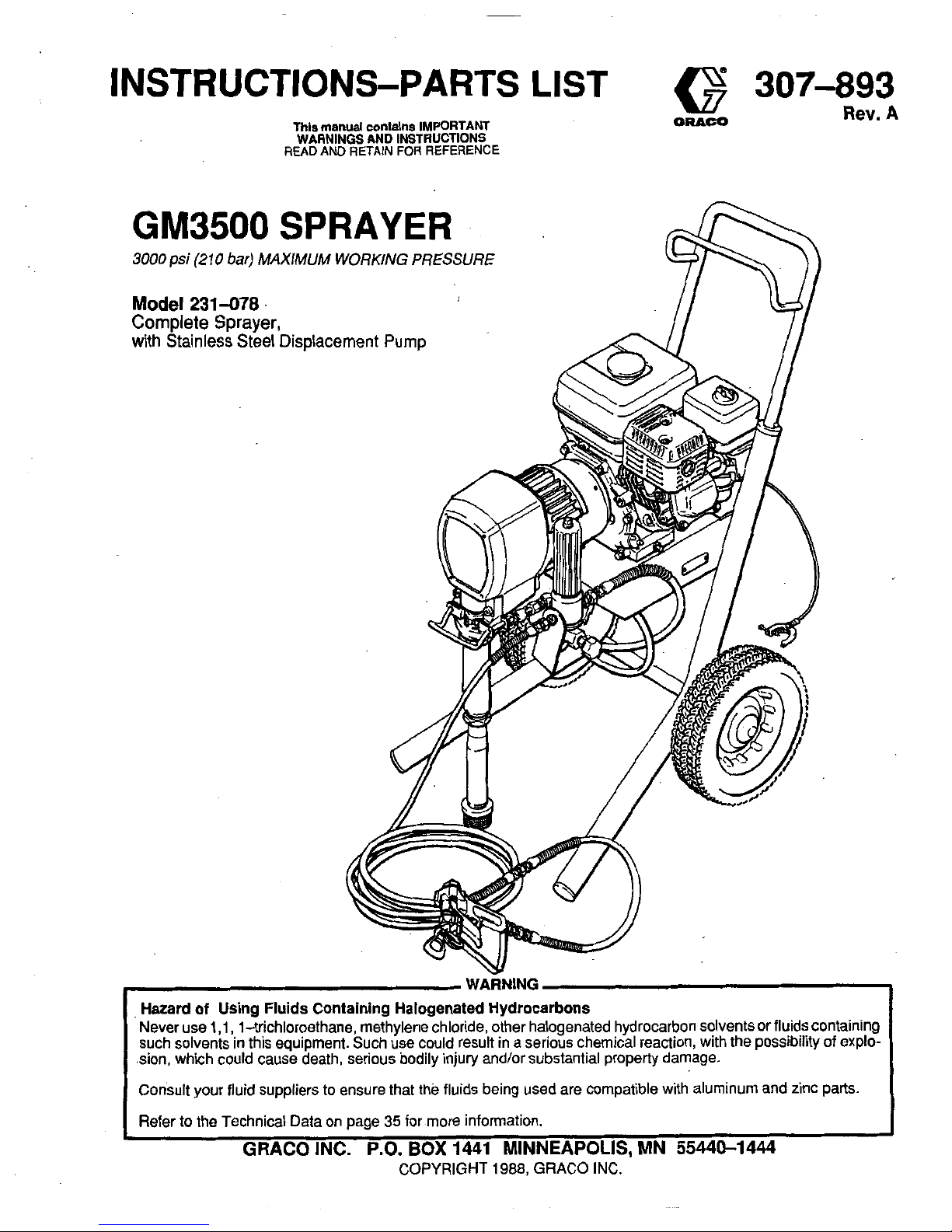
GM3500
SPRAYER
3000
psi
(2
10
bar)
MAXIMUM WORKING
PRESSURE
Model
231-078
Complete Sprayer,
with Stainless Steel Displacement
Pump
307-893
ORACO
Rev.
A
1
GRACO INC.
P.O.
BOX
1441 MINNEAPOLIS. MN 55440-1444
COPYRIGHT
1988,
GRACO INC.
Page 2
TABLE
OF
CONTENTS
Introduction
...............................
2
Warnings
Fueling
...................................
7
Startup
...................................
8
Maintenance
.......................I.....
10
Flushing Guidelines
.......................
11
Troubleshooting Guide
....................
13
Repair
Pressure Control
.......................
15
Pressure Control Calibration
..............
17
Bearing Housing and Connecting Rod
.......
18
Drive Housing
..........................
20
Pinion, Clutch, Field, Clamp, Engine
Pinion Housing Removal
..............
21
Setup
....................................
6
Repairing the Pinion
..................
22
Clutch
.............................
24
Engine
.............................
25
Field and Wiring Harness
..............
26
Clamp
.............................
27
Clutch Housing
......................
27
Reassembly
........................
28
Complete Sprayer, 231-078
...............
30
Pinion Assembly
........................
33
Pressure Control Assembly
................
34
Accessories
..............................
35
Dlmensions
...............................
35
TechnicalData
............................
35
Warranty
.........................
Back Cover
Parts Lists and Drawings
..
INTRODUCTION
GM3500
BASIC
COMPONENTS
(Refer to Fig
3-1)
The GM3500 Sprayer functions and operates differently
than other airless paint sprayers. Read this section to
help you become familiar with the sprayer beforeoperating it.
Pressure Control
The pressure control includes an ONlOFF switch for the
sprayer, the pressure adjusting knob, and a pressure
sensing device. The pressure control engages and disengages the clutch to control pressure.
Engine
The engine is a 3.5 horsepower, four stroke gasoline en-
supply paint. An adjustable throttle allows you to adjust
gine. Its function is
to
drive the displacement pump to
engine speed for large or small orifice spray tips. When
the oil level is too low, the engine shuts
off
automatically.
illuminates to alert you to the problem and protect the en-
If
you try to start the engine without refilling the oil, a light
gine from damage.
Clutch
The clutch is engaged by the electric power generated by
the gasoline engine.The power is controlled by the pres-
sure switch.
Drive
Assembly
The permanently-greased drive assembly transfers
power from the gas engine to the displacement pump.
Displacement Pump
The positive displacement, volume-balanced pump provides equal fluid delivery
on
both the up and down pump
strokes. The pump has a wet-cup which, when filled with
Graco Throat Seal Liquid, helps prevent damage to the
throat packings and piston rod.
..
Fluid Filter
The fluid filter strains the paint to help avoid clogs in the
hose and spray tip. The filter includes a reusable element
and a pressure drain valve for relieving fluid pressure.
Hoses
The grounded, nylon spray hoses have spring guards on
bothends.The50foot(15.2m)hosehasa1/4,in.ID.The
3
foot
(0.9
m), 3/16 in.
ID
whip hose allows flexible gun
movement. The nylon hose material acts as a pulsation
dampener
to
absorb pressure fluctuations.
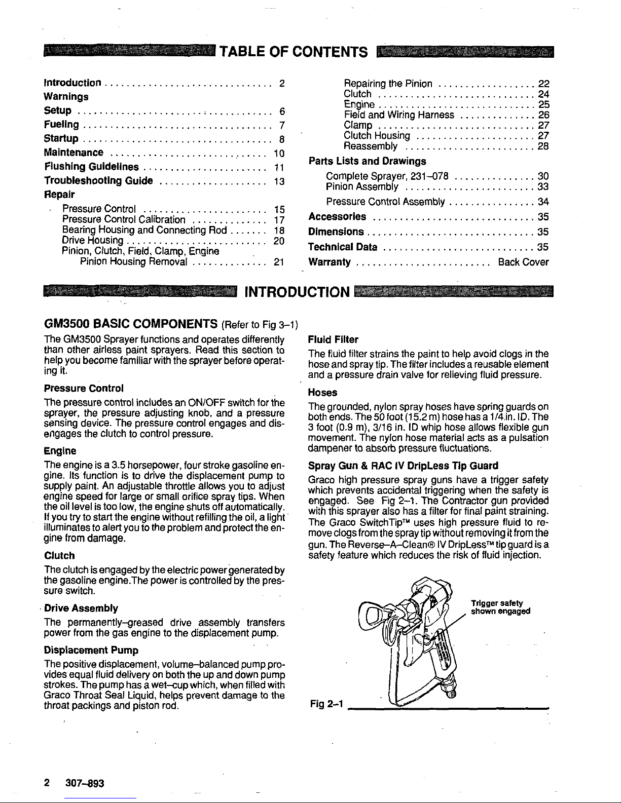
Spray Gun & RAC
IV
DripLess Tip Guard
Graco high pressure spray guns have a trigger safety
which prevents accidental triggering when the safety is
engaged. See Fig
2-1.
The Contractor gun provided
with this sprayer also has a filter for final paint straining.
The Graco SwitchTipTU uses high pressure fluid to re-
gun. The Revers+A-Clean@
IV
DripLessTM tip guard is
a
move clogs from the spray tip without removing it from the
safety feature which reduces the risk of fluid injection.
Trigger
safety
shown
engaged
Fig
2-1
2
307-893
Page 3
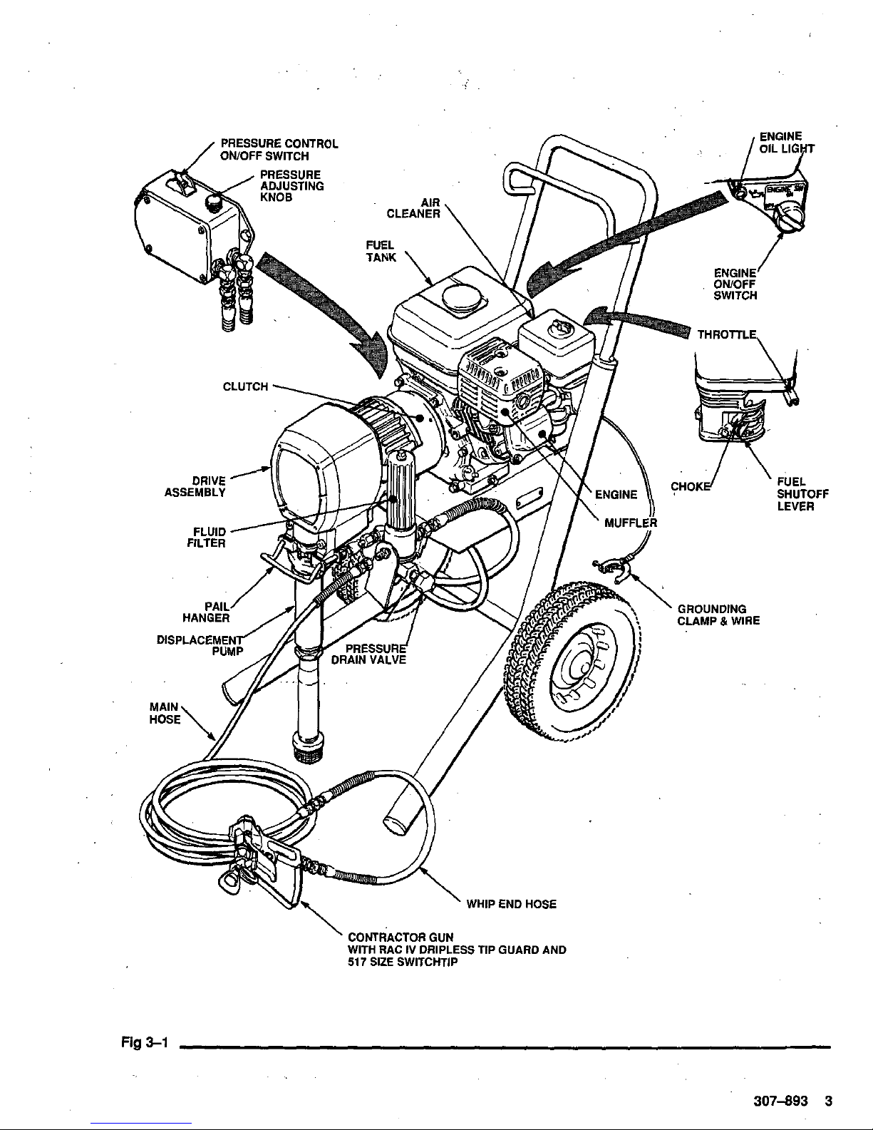
Fig
3-1
307-893
3
Page 4
SAFETY
WARNINGS
HIGH PRESSURE SPRAY CAN CAUSE SERIOUS INJURY.
FOR
PROFESSIONAL USE ONLY. OBSERVE ALL WARNINGS
Read and understand
all
instruction manuals before operating equipment.
FLUID.lNJECTlON HAZARD
General Safety
This equipment generates very high fluid pressure. Spray 6om
the gun, leaks or ruptured components can inject fluid through
yourskin and into your body and causeextremely serious bodily
injury, including the need for amputation. Also, fluid injected or
age.
splashed into the eyes or on the skin can cause serious dam-
NEVER put hand or fingers over the spray tip. NEVER try to
NEVER point the spray gun at anyone or at any part of the body.
"blow back paint; this is NOT an air spray system.
ALWAYS have the tip guard in place on the spray gun when
ALWAYS follow the
Pressure Relief Procedure.
below.before
spraying.
cleaning or removing the spray tip or servicing any system
equipment.
NEVER
try
to
stop or deflect leaks with your hand or body.
Be
sure equipment safety devices are operating properly before
each use.
Medical Alert-Airless Sarav
Wounds
~~ ~~~
MEDICAL
CARE AT 8NCE. DO NOT TREAT AS A SIMPLE
If
any fluid appears to enetrate
your skin,
getEMERGENCY
-r~-,
~~
CUT.
Tell the doctor exactly what fluid was injected.
Note
to
Physician: Injection in the skin is atraumaticinjury.
It
isimportanttotreattheinjurysurgicallyassoonaspossible.
Do
not delay treatment
to
research toxicity. Toxicity is a con-
cern with some exotic coatings injected directly into the
constructive hand surgeon may be
advisable.
blood stream. Consultation with a plastic surgeon or re-
Spray Gun Safety Devices
Be
sure all gun safety devices are operating properly before
cause a malfunction and result in serious bodily injury.
each use.
Do
not
remove or modify any part
of
the gun; this can
Safety Latch
Wheneveryoustopspraying,evenforamoment,alwayssetthe
gun safety latch in the closed or "safe" position. making the gun
tal triggering of the
gun.
inoperative. Failure
to set the safety latch can result in acciden-
Diffuser
The gun diffuser breaks up spray and reduces the risk of fluid
injection when the tip
is
not installed. Check diffuser operation
regularly. Follow the
Pressure Relief Procedure.
below, then
gunfirmlytothe pail. Using the lowest
possiblepressure,trigger
remove the spray tip. Aim the gun into a metal pail, holding the
the gun.
If
the fluid emitted
is
not diffused into an irregular
stream, replace the diffuser immediately.
Tip Guard
ALWAYS have the tip guard in place
on
the spray gun while
spraying. The tip guard alerts you
to
the fluid injection hazard
and helps reduce, but does
not
prevent,
the
risk of accidentally
placing your fingers
or
any part of your body close
to
the spray
tip.
Trigger Guard
Always have the trigger guard in place
on
the gun when spray.
ing
to
reduce the risk of accidentally triggering the gun
if
it is
dropped or bumped.
Spray Tip Safety
the spray tip clogs while spraying, engage thegun safety fkch
Use extreme caution when cleaning or changing spray
ti
s
If
and then remove the spray tip to clean
it.
immediately. ALWAYS follow the
Pressure Relief Procedure
fully relieved and the gun safety latch is engaged.
NEVER wipe
off
build-up around the spray tip until pressure is
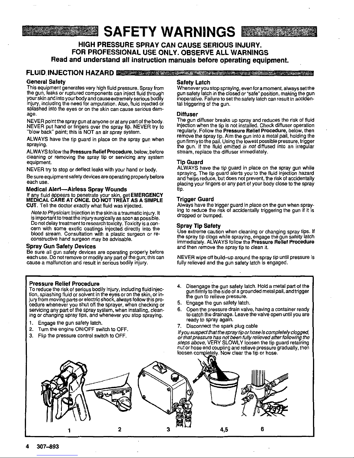
To reduce the risk of serious bodily injury, including fluidinjec-
Pressure Relief Procedure
tion, splashing fluid or solvent in the
e
es
oron the skin, or injury from moving parts or electric shod, always follow this procedure whenever you shut
ofl
the sprayer,
when
checking or
servicing any part
of
the spray system, when installing. clean-
ing or changing spray tips, and whenever you stop spraying.
2.
Turn the engine ON/OFF switch to OFF.
1.
Engage the gun safety latch.
3.
Flip the pressure control switch to OFF.
4.
Disengage the gun safety latch. Hold a metal part of the
the gun to relieve pressure.
gunfirmlytothesideofagroundedmetalpai1,andtrigger
5.
Engage the gun safety latch.
6.
Open the pressure drain valve, having a container ready
to catch the drainage. Leave the valve open until you are
ready to spray again.
7.
Disconnect the spark plug cable
lfyoo suspect that the spray tip orhose is corn lefel clogged,
or thatpressure has not been
fully
relieveda~er fo~o~i"~ the
steps above. VERY SLOWLY loosen the tip guard
retaining
nut or hose end coupling and relieve pressure gradually, then
loosen
completely. Now clear the tip or hose.
1
2
4
307-893
Page 5
MOVING PARTS HAZARD
Moving parts can pinch or amputate your fingers or other body
the sprayer. Follow the Pressure Relief Procedure on page
4
parts. KEEP CLEAR of moving parts when starting or operating
beforechecking orservicing any partofthesprayer. toprevent it
from starting accidentally.
EQUIPMENT MISUSE HAZARD
General
Safety
Any misuse of the spray equipment or accessories, such as
overpressurizing. modifying parts, using incompatible chemi-
cals and fluids, or using worn or damaged parts, can cause
them to ruoture and result in fluid iniection. solashino in the eves
or on the skin, or other serious bodily inju&,'orfire. Explosioi or
property damage.
NEVER alter or modify any part of this equipment: doing
so
could cause
it
to malfunction.
CHECK all spray equipment regularly and repair or replace
worn or damaged parts immediately.
Always wear protective eyewear, gloves, clothing and respira-
tor as recommended by the fluid and solvent manufacturer.
System
Pressure
This sprayer can develop 3000 psi
(210
bar) MAXIMUM
WORKING PRESSURE. Be sure that all spray equipment and
accessories used are rated to withstand this pressure.
DO
NOT
exceed the maximum working pressure of any component or
accessory used in the system.
Fluid
and
Solvent Compatibility
BE SURE that all fluids and solvents used are chemically compatible with the wetted parts shown in iheTECHNlCAL DATA
on
page 35. Always read the fluid and solvent manufacturer's
literature before using them in this sprayer.
HOSE SAFETY
High pressure fluid in the hoses can be very dangerous.
If
the
damage or misuse, the high pressure spray emitted from
it
can
hose develops
a
leak, split or rupture due to any kind
of
wear,
cause a fluid injection injury or other serious bodily injury or
property damage..
ALL FLUID HOSES MUST HAVE SPRING GUARDS ON
BOTH ENDS! The spring guards help protect the hose from
kinks or bends at or close
to
the coupling which can result in
hose rupture.
TIGHTEN all fluid connections securely before each use. High
pressure fluid can dislodge a loose coupling or allow high pressure spray
to
be emitted from the coupling.
tire hose forcuts, leaks, abrasion, bulging cover, or damageor
NEVER use a damaged hose. Before each use, check the en-
movement of the hose couplings.
If
any of these conditions
ex-
ist, replace the hose immediately. DO NOT try
to
recouple high
pressure hose or mend
it
with tape or any other device. A re-
paired hose cannot contain the high pressure fluid.
HANDLE AND ROUTE HOSES CAREFULLY.
Do
not pull on
hoses
to
move equipment. Keep hoses clear of moving parts
and hot surfaces of the pump and gas engine. Do not use fluids
or solvents which are not compatible with the inner tube and
coverofthe hose. DO NOTexpose Graco hose to temperatures
above
180'
F
(82''
C)
or below
-40°
F
(40'
C).
Hose Grounding Continuity
grounded spray system. Check the electrical resistance
of
your
Proper hose grounding continuity is essential to maintaining a
fluid hoses at least once a week.
If
your hose does not have a
tag on it which specifies the maximum electrical resistance,
contact the hose supplier or,manufacturer for the maximum resistance limits. Use a resistance meter in the appropriate range
for your hose to check the resistance. lfthe resistance exceeds
the recommended limits, replace
it
immediately. An un-
grounded or poorly grounded hose can make your system hazardous. Also read FIRE
OR
EXPLOSION HAZARD.
FIRE'OR
EXPLOSION
HAZARD
Static electricity is created by the flow of fluid through the pump
2.
Fluid
hoses: use only grounded hoses with a maximum of
and hose.
If
every part of the spray equipment is not properly
500feet(l50m)combinedhoselen
thtoensuregrounding
grounded, sparking may occur, and the system may become
continuity. See Hose Grounding
8
ontlnuity.
hazardous. Sparking may also occur when plugging in or un-
3. Spraygun:obtain grounding through connection to a prop-
plugging a power supply cord or using a gasoline engine.
Sparks can ignite fumes from solvents and the fluid being
erly grounded fluid hose and sprayer.
sprayed, dust particles and other flammable substances,
4.
Object being sprayed: according to local code.
fire orexplosion and serious bodily injury and property damage.
whether you are spraying indoors oroutdoors, and can cause a
5,
Fluid
supp~y
conta;ner:
to
local
code.
6.
All solvent pails used when flushing, according to local
If
you experience any static sparking or even a slight shock
while using this equipment,
STOP
SPRAYING IMMEDI-
code. Use only metal pails, which are conductive. Do not
ATELY. Check the entire system for proper grounding. Do not
place the pail on a non-conductive surface, such as paper
use the system again until the problem has been identified and
7,
To
conti.;iru
when
orrelieving
or cardboard, which interrupts the grounding continuity.
corrected.
pressure, always hold a metal part of the gun firmly to the
Grounding
side of a grounded metal pail, then trigger the gun.
To reduce the risk of static sparking, ground the sprayer and all
Flushing
safety
other spray equipment used or located in the spray area.
tions
for
your
area
and
type
of
equipment,
BE
SURE
to
ground
splashing by following theflushlng procedure given
on
Page
10
CHEcKyour
localelectricalcodefordetailedgrounding
inStluC-
Reduce the risk of fluid injection Wry, static sparking, or
all of this spray equipment:
of this manual. FollowthePressure Relief Procedureon page
4,
and remove the spray tip before flushing. Hold ametal part of
1.
Sprayer: connect a ground wire and clamp (supplied) to a the gun firmly
to
the side of a grounded metal pail and use the
true earth ground. lowest possible fluid pressure during flushing.
GASOLINE ENGINE HAZARD
NEVER
fill
the fuel tank while the engine is running
or
hot. fuel NEVER operate the engine in a closed building unless the en-
spilled
on
a hot surface can ionite and cause a fire. cline exhaust is DiDed outside. The exhaust contalns carbon
307-893
5
Page 6
SETUP
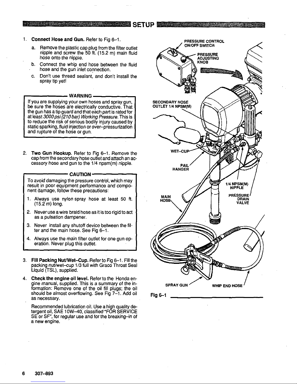
1.
Connect Hose
and
Gun.
Refer
to
Fig
6-1.
a. Remove the plastic cap plug from the filter outlet
nipple and screw the
50
ft.
(15.2
m) main fluid
hose onto the nipple.
b. Connect the whip end hose between the fluid
hose and the gun inlet connection.
c. Don't use thread sealant; and don't install the
spray tip yet!
WARNING
be sure the hoses are electrically conductive. That
If
you are supplying your own hoses and spray gun,
the gun has a tip guard and that each part is rated for
at least
3000psi(210
bar) Working Pressure. This is
to
reduce the risk of serious bodily injury caused by
static sparking, fluid injection or over-pressurization
and rupture of the hose or gun.
~~ ~ ~~ ~ ~
2.
Two
Gun Hookup.
Refer to Fig
6-1.
Remove the
cap from the secondary hose outlet and attach an accessory hose and gun to the
114
npsm(m) nipple.
CAUTION
To
avoid damaging the pressure control, which may
result in poor equipment performance and component Clamage, follow these precautions:
1.
Always use nylon spray hose at least
50
ft.
2.
Never use awire braid hose as it is
too
rigid
to
act
3.
Never install any shutoff device between the fil-
4.
Always use the main filter outlet for one gun
op-
(15.2
m) long.
as a pulsation dampener.
ter and the main hose. See Fig
6-1.
eration. Never plug this outlet.
3.
Fill Packing Nuwet-Cup.
Refer to Fig
6-1.
Fill the
packing nuffwet-cup
1/3
full with Graco Throat Seal
Liquid (TSL), supplied.
4.
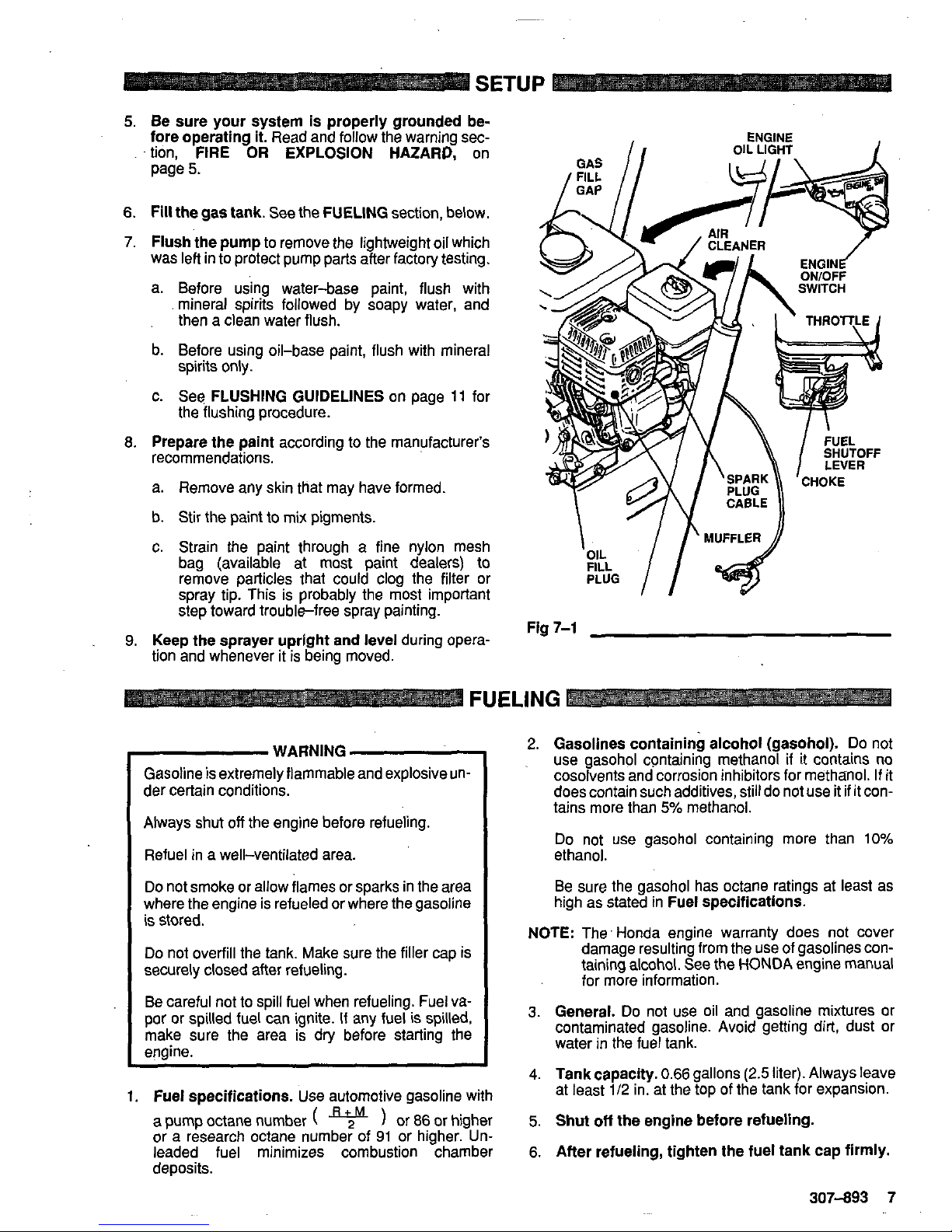
Check the engine
oil
level.
Refer
to
the Honda engine manual, supplied. This is a summary of the information: Remove one of the oil fill plugs; the oil
should be almost overflowing. See Fig
7-1.
Add oil
as necessary.
tergent oil, SAE
1
OW-40,
classified "FOR SERVICE
Recommended lubricatiqn oil. Use a high quality de-
SE
or
SF",
for regular use and for the breaking-in
of
a new engine.
"
PRESSURE CONTROL
ONlOFF
SWITCH
SECONDARY
H
OUTLET
1/4
NP
WHIP END HOSE
Fig
6-1
6
307-893
Page 7
SETUP
5.
Be sure your system is properly grounded
be-
fore operating it.
Read and follow the warning sec-
tion,
FIRE
OR
EXPLOSION HAZARD,
on
page
5.
6.
Fill the gas tank.
See the
FUELING
section, below.
7.
Flush the pump
to
remove the lightweight oil which
was left in
to
protect pump parts after factory testing.
a. Before using water-base paint, flush with
mineral spirits followed by soapy water, and
then a clean water flush.
b. Before using oil-base paint, flush with mineral
c. See
FLUSHING GUIDELINES
on page 11 for
8. Prepare the paint
according
to
the manufacturer's
spirits only.
the flushing procedure.
recommendations.
a. Remove any skin that may have formed.
b. Stir the paint to mix pigments.
c.
Strain the paint through a fine nylon mesh
bag (available at most paint dealers) to
spray tip. This is probably the most important
remove particles that could clog the filter or
step toward trouble-free spray painting.
9.
Keep the sprayer uprlght and level
during opera-
tion and whenever it
is
being moved.
\
/
MUFFLER
//
Fig
7-1
FUELING
-
WARNING
Gasoline
is
extremely flammable and explosive un-
der certain conditions.
Always shut
off
the engine before refueling.
Refuel in a well-ventilated area.
Do
not smoke or allow flames or sparks in the area
where the engine is refueled or where the gasoline
is
stored.
securely closed after refueling.
Do
not overfill the tank. Make sure the filler cap is
por or spilled fuel can ignite.
If
any fuel is spilled,
Be careful
not
to spill fuel when refueling. Fuel va-
engine.
make sure the area is dry before starting the
1.
Fuel specifications.
Use automotive gasoline with
a
pump octane number
(
or
86
or higher
or a research octane number of 91 or higher. Un-
deposits.
leaded fuel minimizes combustion chamber
2.
Gasolines containing alcohol (gasohol).
Do not
use gasohol containing methanol
if
it contains
no
cosolvents and corrosion inhibitors for methanol. If it
does contain such additives, still do not use it
if
it con-
tains more than
5%
methanol.
Do not use gasohol containing more than
10%
ethanol.
high as stated in
Fuel specifications.
Be sure the gasohol has octane ratings at least as
NOTE:
The' Honda engine warranty does not cover
damage resulting from the use of gasolines containing alcohol. See the
HONOA
engine manual
for more information.
3.
General.
Do
not
use oil and gasoline mixtures or
contaminated gasoline. Avoid getting dirt, dust or
water in the fuel tank.
4.
Tank capacity. 0.66
gallons
(2.5
liter). Always leave
5.
Shut
off
the engine before refueling.
6. After refueling, tighten the fuel tank cap flrmly.
at least
1/2
in. at the top of the tank for expansion.
307-893 7
~~
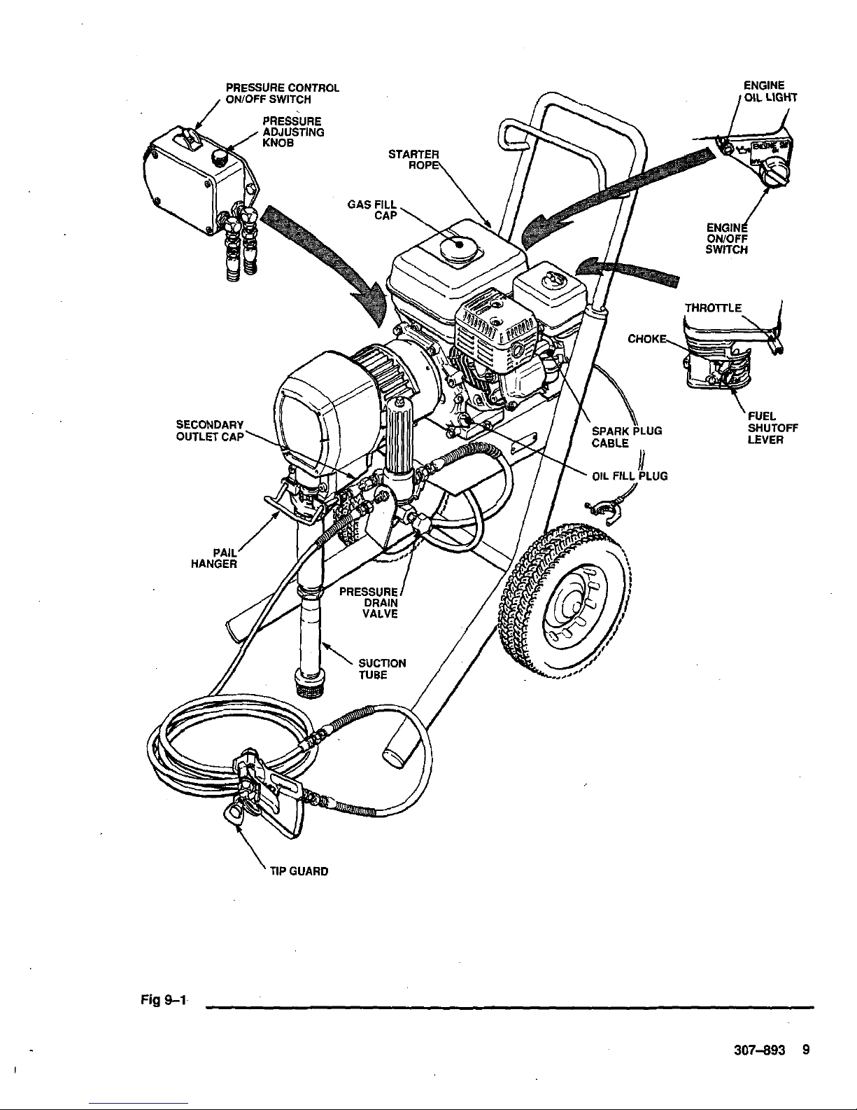
Page 8
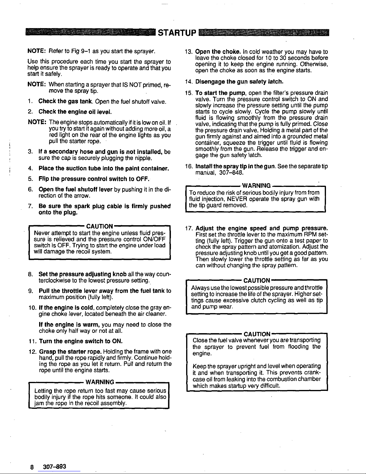
NOTE:
Refer to Fig
9-1
as you start the sprayer.
Use this procedure each time you start the sprayer to
help ensure the sprayer is ready to operate and that you
start it safely.
NOTE:
When starting a sprayer that
IS
NOT primed, re-
move the spray tip.
1.
Check the gas tank.
Open the fuel shutoff valve.
2.
Check the engine oil level.
NOTE:
The engine stops automatically if it is low on oil. If
you try to start it again without adding more oil, a
red light on the rear of the engine'lights as you
pull the starter rope.
3.
If
a
secondary hose and gun is not installed,
be
4.
Place the suction tube into the paint container.
5.
Flip the pressure control switch to OFF.
6.
Open the fuel shutoff lever
by pushing it in the di-
7.
Be sure the spark plug cable is firmly pushed
sure the cap is securely plugging the nipple.
!
rection
of
the arrow.
onto the'plug.
Never attempt to start the engine unless fluid pres-
sure is relieved and the pressure control ON/OFF
switch
is
OFF. Trying to stat? the engine under load
will damage the recoil system.
IcAuT1oNl
8.
Set the pressure adjusting knob
all the way coun-
terclockwise to the lowest pressure setting.
9.
Pull the throttle lever away from the fuel tank
to
maximum position (fully left).
10.
If
the engine is cold,
completely close the gray en-
gine choke lever, located beneath the air cleaner.
If
the engine is warm,
you may need to close the
choke only half way or not at all.
11.
Turn the engine switch to ON.
12.
Grasp the starter rope.
Holding the frame with one
hand, pull the rope rapidly and firmly. Continue holding the rope as you let it return.
Pull
and return the
rope until the engine starts.
WARNING
Letting the rope return too fast may cause serious
bodily injury
if
the rope hits someone. It could
also
jam the rope in the recoil assembly.
~
13.
Open the choke.
In cold weather you may have to
opening it to keep the engine running. Otherwise,
leave the choke closed for
10
to
30
seconds before
open the choke as soon as the engine starts.
14.
Disengage the gun safety latch.
15.
To start the pump,
open the filter's pressure drain
valve. Turn the pressure control switch to
ON
and
slowly increase the pressure setting until the pump
starts to cycle slowly. Cycle the pump slowly until
fluid is flowing smoothly from the pressure drain
valve, indicating that the pump is fully primed. Close
the pressure drain valve. Holding a metal part of the
gun firmly against and aimed into a grounded metal
container, squeeze the trigger until fluid is flowing
smoothly from the gun. Release the trigger and engage the gun safety latch.
16.
Install the spray tip in the gun.
See the separate tip
manual,
307-848.
I'wARN'NGl
To
reduce the risk of serious bodily injury from from
the tip guard removed.
fluid injection,
NEVER
operate the spray gun with
17.
Adjust the engine speed and pump pressure.
First set the throttle lever to the maximum
RPM
setting (fully left). Trigger the gun onto a test paper to
check the spray pattern and atomization. Adjust the
pressure adjusting knob until you get a good pattern.
Then slowly lower the throttle setting as far as you
can without changing the spray pattern.
CAUTION
Always use the lowest possible pressure and throttle
setting to increase the life of the sprayer. Higher settings cause excessive clutch cycling as well as tip
and pump wear.
Close
the fuel valve whenever you are transporting
CAUTION
the sprayer to prevent fuel from flooding the
engine.
Keep the sprayer upright and level when operating
case oil from leaking into the combustion chamber
it and when transporting it. This prevents crank-
which makes startuD verv difficult.
8
307-893
Page 9
Fig
9-1-
307-893
9
Page 10

MAINTENANCE
-WARNING
I
To
reduce the risk
of
serious bodily injury, including
fluid injection or splashing in the eyes or on the skin,
or injury from moving parts, always follow the
Pres-
sure Relief Procedure Warning
on page
11
before
checking, adjusting, cleaning and shutting down the
sDraver. Disconnect the SDark DIua.
CAUTION
tions, refer to the separate engine manual, supplied.
For detailed engine maintenance and specifica-
DAILY:
Checkthe engine
oil
level and
fill
as necessary.
WEEKLY:
Check the level of the
TSL
in the displace-
DAILY:
Check and
fill
the gas tank.
ment pump packing nut. Fill it
if
necessary. Keeping
TSL
in the nut helps lubricate the packings.
AFTER THE
FIRST
20
HOURS
OF
OPERA-
TION:
Drain the oil and refill with clean oil.
the element. Replace the element
if
necessary.
If
operat-
WEEKLY:
Remove the cover of the air filter and clean the
Oil.
ing in an unusually dusty environment, check the filter
daily and replace
if
necessary.
SPARK PLUG:
Use only a (NGK)
BPGES
or
BPR6ES
plug. Gap the plug to
0.025-0.030
in.
(0.7-0.8
mm). Be
Replacement elements can be purchased from your
lo-
sure to use a spark plug wrench when installing and re-
tal
Honda dealer. moving the plug.
AFTER EACH
100
HOURS
OF
OPERATION:
Change
10
307-893
Page 11
FLUSHING GUIDELINES
I
WARNING
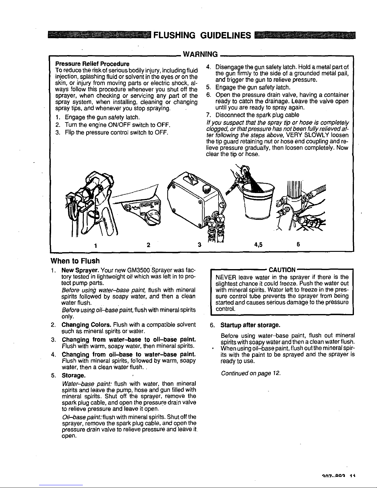
Pressure Relief Procedure
Toreduce the riskof serious bodily injury, including Ruid
the
gun
firmly
to
the
side
of
a
grounded
metal
pail,
4.
Disengage the gun safety latch. Hold a metal part of
skin, or injury from moving parts or electric shock, al-
injection, splashing fluid or solvent in the eyes or on the
and
trigger
the
gun
to
relieve
pressure,
ways follow this procedure whenever you shut
off
the
5.
Engage
the
gun
latch.
sprayer, when checking or servicing any pari of the
6.
Open the pressure drain valve, having a container
spray system, when installing, cleaning or changing
ready to catch the drainage. Leave the valve open
spray tips, and whenever you stop spraying.
.
until you are ready to spray again.
1.
Engage the gun safety latch.
7.
Disconnect the spark plug cable
2.
Turn the engine ON/OFF switch to OFF.
If
you suspect that the spray tip or hose
is
completely
3. Flip the pressure control switch to OFF.
clogged, or that pressure has not been
fully
relieved
af-
ter fobwing the steps above,
VERY
SLOWLY loosen
the tip guard retaining nut or hose end coupling and re-
clear the tip or
hose.
lieve pressure
gradually, then loosen completely. Now
1
2
When to Flush
1.
New Sprayer.
Your new GM3500'Sprayer was fac-
tory
tested in lightweight oil which was left in to pro-
tect pump parts.
Before
using
water-base paint, flush with mineral
water flush.
spirits followed by soapy water, and then a clean
only.
Before using oil-basepaint, flush with mineral spirits
2.
Changing Colors.
Flush with a compatible solvent
such
as
mineral spirits or water.
3.
Changing from water-base to oil-base paint.
Flush with warm, soapy water, then mineral spirits.
4.
Changing from oil-base to water-base paint.
Flush with mineral spirits, followed by warm, soapy
water, then a clean water flush.
Water-base paint: flush with water, then mineral
spirits and leave the pump, hose and gun filled with
mineral spirits.
Shut
off
the sprayer, remove the
spark plug cable, and open the pressure drain valve
to relieve pressure and leave it open.
Oil4asepaint:flush with mineral spirits. Shut
off
the
sprayer, remove the spark plug cable, and open the
pressure drain valve to relieve pressure and leave it.
open.
5.
Storage.
-
CAUTION
NEVER leave water in the sprayer
if
there is the
slightest chance it could freeze. Push the water out
with mineral spirits. Water left to freeze in the pressure control tube prevents the sprayer from being
started and causes serious damage to the pressure
control.
6.
Startup after storage.
spirits with soapy water and
then a
clean water flush.
Before using water-base
paint,
flush
out mineral
*
When using oil-base paint, flush out the mineralspir-
its with the paint to be sprayed and the sprayer is
ready
to
use.
Continued on page
12.
Page 12

FLUSHING
GUIDELINES
How
to
Flush
1.
Follow the Pressure Relief Procedure Warning on
6.
Disengage the gun safety latch. Point the spray gun
page
1
1.
into a metal waste container and with a metal part of
the gun firmly touching the metal container, squeeze
the gun trigger. See Fig
12-2.
This procedure helps
reduce the risk of static sparking and splashing. Start
the sprayer, trigger the gun and slowly turn the pressure adjusting knob clockwise just until the pump
starts. Keep the gun triggered until clean solvent
comes from the nozzle. Release the trigger and engage the gun safety latch.
2.
Remove the filter bowl and screen; see manual
307-273, supplied. Clean the screen separately and
install the bowl without the screen to flush it. See Fig
12-1.
FILTER
BOWL
SCREEN
'
FILTER
SUPPORT
PRESSURE
DRAIN VALVE
Fig
12-1
7. Check all fluid connections for leaks.
If
anyJeak, first
follow the Pressure Relief Procedure Warning on
page
11.
Now tighten the connections, start the
sprayer, and recheck the connections for leaks.
8.
Remove the suction tube from the pail. Disengage
the gun safety and trigger the gun to force solvent
from the hose.
Do
not let the pump run dry for more
than
30
seconds to avoid damaging the pump packings! Then follow the Pressure Relief Procedure
Warning on page
11.
9.
Leave the pressure drain valve open until
you
are
bowl and reinstall the clean screen. Reinstall the
ready
to
use the sprayer again. Unscrew the filter
bowl, hand tight only.
IO.
If
you flushed with mineral spirits and are going
to
use a water-base paint, flush with soapy water fol-
sure Rellef Procedure Warning on page
11.
lowed by a clean water flush. Then follow the Pres-
3. Close the filter's pressure drain valve.
4.
Pour one-half gallon
(2
liters) of compatible solvent
into a grounded metal pail. Put the suction tube
in
the
pail.
5.
Remove the spray tip from the gun.
-1
Fig
1
To
reduce the risk of static sparking and splashing,
always remove the spray tip form the gun, and hold
a metal part of the gun firmly to the side
of
and aimed
into
a
grounded metal pail when flushing.
METAL
TO
META
CONTACT WHEN
FLUSHING
12
307-893
Page 13

I
WARNING
To reduce the risk of serious bodily injury, including fluid
5.
Engage the gun safety latch.
Pressure Relief Procedure
from
moving
always
follow
this when-
6.
Open the fluid pressure drain valve and leave
it
injection, splashing in the eyes or on the skin, or injury
you shut
off
the sprayer, checking, adjust or clean the open until you start the sprayer again.
system, or change spray tips.
7.
Disconnect the spark
plug
cable.
1. Engage the gun safety latch.
lfyou
suspect that the hose or
tip
is
completely clogged
2. Turn the engine ON/OFF switch to OFF. or that pressure
is not
fully
relieved affer
following
the
3.
Flip the pressure control switch to OFF.
stepsabove, VERY SLOWLY loosen a hose end fitting
or the tip guard retaining nut and relieve pressure
4.
Disengage the gun safety latch. Holding a metal part
gradually. Now clear the tip or hose.
trigger the gun.
of the gun firmly to the side of agrounded metal pail,
Check everything in the guide before disassembling the sprayer.
JROBLEM
fnginekprayer won't start
3ngine won't pull over.
?as engine operates but
jisplacement pump doesn't
)perate
CAUSE
I
SOLUTION
Engine switch not
ON
I
Turn on.
Engine
oil
level low
Try starting engine.
If
light on rear of
engine glows, replenish oil..
Spark plug cable disconnected or Connect cable on top of engine or respark plug bad place spark plug.
Out
of gas
Water frozen in pressure control.
Replenish
Graco dealer for
rep-:?
Return
pressure
control to authorized
Oil seepage into combustion
Remove spark plug. Pull engine over
chamber.
3
or 4 times. Clean and replace plug.
Try to start. Keep sprayer upright to
avoid seepage.
-,
Pressure control switch turned OFF
Clean filter.
Displacement pump outlet filter dirty
Increase pressure.
Pressure setting too low
Turn on.
or clogged
Tip or tip filter clogged Clean tip or tip filter.
Displacement pump rod seized by dry
Service pump. See
307-806.
paint
I
Connecting rod worn or damaged
Check wiring connections. See page
Electrical power not energizing
field
Replace. See page
20.
Driie housing worn or damaged
Replace. See page
18.
15.
With pressure control switch ON and
test light to check continuity across
pressure turned to
MAXIMUM,
use a
black and wire wires from pressure
control.
Have pressure control checked by
authorized Graco dealer.
Clutch worn or damaged
Service. See page
21.
Pinion assembly worn
or
damaged
Service. See page
24.
'
Continued on page
14
307-893 13
Page 14

TROUBLESHOOTING
GUIDE
PROBLEM
Displacement
.
pump outpu
low on upstroke
low on downstroke or bot1
Displacement pump outpu
strokes
Paint leaks into wetcup
Low fluid delivery
Spitting from gun
CAUSE
Pump inlet screen clogged
Piston ball check not seating
Piston packings worn or damaged
Displacement pump sleeve gasket
worn or damaged
Pump inlet screen clogged
Piston packings worn or damaged
properly
Intake valve ball check not seating
Engine RPM too low
~~~ ~
Clutch worn or damaged
Loose wet-cup
Throat packings worn or damaged
damaged
Displacement rod worn or
Pump inlet screen clogged
Pressure setting
too
low
Engine RPM
too
low
Dirty outlet filter, tip filter or tip
Large pressure drop in hose
Air in fluid pump or hose
Tip partially clogged
Fluid supply is low or empty
SOLUTION
Clean.
Service piston ball check.
Replace packings,
Replace.
Clean.
Replace packings.
Clean and service.
Increase throttle setting. See Startup,
Step 17, page
8.
Replace. See page
24.
Tighten just enough to stop leakage.
Replace packings. See 307-793.
Replace. See 307-793.
Clean.
Increase pressure. See Startup, Step
17, page
8.
Increase throttle setting. See Startup,
Step 17, page
8.
Clean.
Use larger diameter hose.
Check for loose connections at intake
and tiohten. Then mime the
ix.mD.
See STaiup, page
8:
Clear,
Refill and reprime the pump. See
Startup, page
8.
Check fluid supply
often to Drevent running dry.
,.
14
307-893
Page 15

REPAIR
Pressure Control Replacement
WARNING
To
reduce the risk
of
serious bodily injury, including
fluid injection or splashing in the eyes or on the skin,
or injury from moving parts, always follow the
Pres-
sure.Relief Procedure Warning
on
page 13 before
checking, adjusting, cleaning and shutting down the
sprayer. Disconnect the spark plug cable.
1. Disconnect both hoses at the pressure control (63),
holding the elbows firmly. See the
CAUTION
below.
Take note
of
the original location of each hose
to
be
sure you reassemble them correctly at the end of this
procedure. See Fig 15-1,
CAUTION
DO
NOTallow the elbow (314)
to
turn when remov-
ing or connecting the hoses. Turning the elbows can
2.
Working under the engine mounting plate
of
the cart,
disconnect the red, black and white wires. Then remove the three nuts (61) and lockwashers
(9)
from
the capscrews
(62)
which hold the pressure control
trol. See Fig
15-2.
bracket
(67)
to
the cart. Remove the pressure con-
3. Remove the pressure control cover and screws
(76,64) and the four screws
(65)
holding bracket
(67)
Fig
15-1
to the pressure control. See Fig 15-1.
trol wires. See Fig
15-2.
(see
page
17)
4. Remove the wire clamp
(32)
from the pressure con-
procedure
continued
on
newt
page
VIEW
FROM
UNDER ENGINE MOUNTING
PLATE
Fig
15-2
307-893
15
Page 16

~
REPAIR
5.
Disconnect the wires from the rectifier
(307).
Re-
9.
Reassemble
in
the reverse order. Be Sure
to
reinstall
move the screw
(311),
nut
(306)
and lockwasher
(305).
See Fig
16-1,
the wire clamp
(32)
on the new pressure control
wires. Fasten both clamps to the cart with the
6.
Unscrew the connector
(313)
from the box, pulling
the wires out with it.
same screws, lockwashers and nuts
(62,9,61)
which
hold the bracket
(67)
to the cart. See Fig
15-2.
7.
Holding the hex of the adapters
(A)
at the control box
with a wrench, remove the elbows
(314).
8.
Removethescrew(310)andiockwashers(305)from
10.
Perform the Pressure
Control Calibration
proce-
the ground wire
(308).
dure on the next page before regular operation of the
sprayer.
31 1,305,306
RED
RECTIFIER
(307)
CONNECTIONS
Fig
16-1
16
307-893
Page 17

REPAIR
Pressure
Control Calibration
(See
Fig
17-1)
L
WARNING
USE EXTREME CAUTION WHEN PERFORMING THIS CALIBRATION PROCEDURE
to reduce the risk of a fluid
injection injury or other serious bodily injury which can result from component rupture, electric shock, fire, explosion,
or moving parts.
This procedure sets the sprayer to 182-210 bar
MAXIMUM WORKING PRESSURE.
This procedure must be performed whenever the
pressure control assembly is removed and reinstalled
or replaced to be sure the sprayer is properly cali-
brated.
Improper calibration can cause the sprayer
to
over-
pressurize and result in component rupture, fire or ex-
plosion. It may also prevent the sprayer from obtaining
sprayer performance.
the maximum working pressure, resulting in poor
NEVER attempt
to
increase the fluid outlet pressure
by performing these calibrations in any other way.
NEVER EXCEED 210 bar MAXIMUM WORKING
PRESSURE. Normal. operation
of
the sprayer at
fire or explosion.
higher pressures could result in component rupture,
ALWAYS use a new 15.2 m spray hose rated for at
when performing this procedure.
A
used, under-rated
least 210 bar MAXIMUM WORKING PRESSURE
hose could develop a high pressure leak or rupture.
AVOID touching the wire in the pressure control assembly when the control box cover is removed, to reduce the risk of electric shock.
Service Tools Needed:
NEW 15.2 m, 231 bar flexible, nylon airless spray
hose, Part No. 21C-541
New 0.023 size spray tip.
0-350 bar fluid-filled pressure gauge, Part No.
20 liter pail and water
Mineral spirits
1.
Follow
the
Pressure Relief Procedure Warning
on
page 13.
2. Install the new 15.2 m spray hose to the sprayeroutlet. On the other end of the hose, install the gun and a
gauge in the top port
(6
-
See
fig
15-1)
of the fluid
new ,023 size tip. Install the fluid-filled pressure
filter. Remove the pressure control cover.
3. With the gun safety latch engaged, start the engine
(only). Using a 318” ignition wrench, turn the pressure
adjustment nut
(E)
clockwise
two
full turns. See Fig
the minimum setting, turn the sprayer switch
ON.
17-1. With the pressure control knob (D) turned to
THE DISPLACEMENT PUMP SHOULD NOT CYCLE
If
if
does
cycle,
shut the sprayer switch OFF, disengage the gun safety latch, trigger the gun into a
grounded waste container until pressure is relieved,
and engage the latch again. Turn the nut
(E)
a little
further clockwise. Turn the sprayer on again to be
sure
THE
PUMP
DOES
NOT
CYCLE.
4.
Increase the throttle setting and then the pressure
control setting to the maximum while triggering the
gun. Keep the gun triggered while observing the
pressure at which the pump stalls, which should be
approximately 210 bar.
NOTE:
When the gun trigger is released, it is normal for
the stall pressure
to
be 21 7 to 238 bar, during this
procedure.
/f
the
pressure
is
not
210
bar, turn the adjusting nut
clockwise
to increase pressure to obtain exactly
(E)
clockwise
to reduce pressure and
counter-
21
0
bar pressure.
102-81
4
fore the pressure starts to rise again.
Then note the pressure to which the gauge drops be-
entia1 wheel
(A)
clockwise
to bring the pressure to
IffhepressuredropstobeIow18Zbar,turnthediffer-
182 bar.
the differential wheel (A)
counterclockwise
to de-
If
the pressure stops
dropping
before
182
bar, turn
crease the pressure.
5. Follow the
Pressure Relief Procedure Warning
on
page
13.
Install the pressure control cover. Flush the
water out with mineral spirits, relieve pressure again,
and then
remove
all
the
test
equipment.
A\
/D
Fig
17-1
307-893
17
Page 18

REPAIR
Bearing
Housing
&
Connecting
Rod
WARNING
To
reduce the risk of serious bodily injury, including
fluid injection, splashing fluid in the eyes or on the
skin, or injury from moving parts, always follow the
Pressure Relief Procedure
Warnins on page 13
before repairing any part of the sprayer. Disconnect
the soark
Dlua
cable.
NOTE:
Steps 1
to
13 refer
to
Fig 18-1.
1. Remove the front cover and screws (23’68).
2.
Unscrew the suction tube (30) from the pump, hold-
pump from loosening.
ing a wrench on the pump intake valve
(B)
to
keep the
3. Disconnect the pump outlet hose (59) from the displacement pump outlet nipple (87).
4.
Use a screwdriver
to
push aside the retaining spring
(26) at the top of the pump. Push the pin (25)
out
the
rear.
5.
Loosen the jam nut (27) with an adjustable wrench.
Unscrew and remove the displacement pump.
6.
Use a hex key wrench to remove the four screws (73)
and lockwashers (74) from the bearing housing.
7. While pulling the connecting rod (22) with one hand,
with a plastic mallet to loosen it from the drive hous-
lightly tap the lower rear
of
the bearing housing (21)
ing (20).
Pull
the bearing housing and the connecting
rod assembly (22)
off
the drive housing.
8.
Inspect the crank
(A)
for excessive wear and replace
parts as needed.
9.
Evenly lubricate the inside of the bronze bearing
(F)
in !he bearing housing (21.) and the inside of the con-
ally pack the roller bearing
(E)
in the connecting rod
necting rod link (D) with high quality motor oil. Liber-
assembly (22) with bearing grease.
10.
Assemble the connecting rod (22) and bearing housing (21).
11.
Clean the mating surfaces of the bearing and drive
housings.
12. Align the connecting rod with the crank
(A)
and care-
fully align the locating pins
(C)
in the drive housing
the bearing housing onto the drive housing or tap it
(20) with the holes in the bearing housing
(21).
Push
into place with a plastic mallet.
CAUTION
13. Install the screws (73) and lockwashers
(74)
on the
bearing housing and tighten evenly to 125-145 in-lb
(14-16
Nm).
18
307-893
Page 19

REPAIR
NOTE:
Refer to Fig
19-1
for Step
14.
14.
Screw the displacement pump about
3/4
of the way
into the bearing housing
(21).
Hold the pin
(25)
up to
the pin hole in the connecting rod assembly
(22)
and
continue screwing in the pump until the pin slides
easily into the hole. Back
off
the pump until the top
threads of the pump cylinder are flush with the face
of
the bearing housing and the outlet nipple
(87)
is fac-
groove all
the
way
around the connecting rod.
ing back. Push the
retaining spring
(26)
into
the
Tighten the locknut
(27)
very tight - about.65 to
75
ft-lb
(90
to
100
N.m) -with a
2-1/4
in. open end
wrench and a light hammer.
WARNING
To reduce the risk of the pin
(25)
being projected into
the air and resulting in serious bodily injury, including
injury
to
the eyes, or property damage, including
damage to the pump connecting rod or bearing
housing:
Be sure the retaining spring
(26)
is firmly in the
groove all the way around, to prevent the pin
(25)
from working loose due to vibration.
If
the pin works loose, it or other parts could break
off
due to the force of the pump action. These parts
could be projected through the air.
15.
Reinstall the front cover and screw
(23,68).
Recon-
See Fig
18-1.
nect the suction tube
(30)
and pump outlet hose
(59).
Fig
19-1
307-893
19
Page 20

REPAIR
Drive
Housing
WARNING
To reduce the risk of serious bodily injury, including
fluid injection, splashing fluid in the eyes or on the
skin, or injury from moving parts, always follow the
before repairing any part of the sprayer. Discon-
Pressure Relief Procedure Warning
on
page
13
nect the spark plug cable.
NOTE: Refer to Fig 20-1 for this procedure.
1.
Remove the front cover and screws
(23,68)
2.
Disconnect the pump outlet hose (59) from the dis-
placement pump nipple
(57).
3.
Use a hex key wrench to remove the two screws
(I
0)
and lockwashers (1
1)
from the bottom front of the
pinion housing (1911). Then remove the top
two
screws
(IO)
and lockwashers
(1
1).
4.
Working from the front
of
the drive housing, remove
the two screws
(73)
and lockwashers
(74).
5.
Lightly tap around the drive housing with a plastic
mallet to loosen it from the pinion housing.
6.
While holding the connecting rod
(22)
with one hand,
lightly tap the back of the bearing housing
(21)
to
loosen the drive housing. Then pull the drive housing
straight
off
the pinion housing.
CAUTION
moving the drive housing
(20).
It iseasily damaged
DO NOT allow the gear cluster
(1
8)
to fall when re-
if
dropped. The gear may stay engaged in either the
drive housing or pinion housing.
each end of the gear cluster, or allow them to fall be-
DO
NOT lose the thrust balls (2Oc or 19j) located at
tween gears. The ball, which is heavily covered with
grease, usually stays in the shaft recesses, but
could be dislodged.
If
caught between gears and
not removed, the balls will seriously damage the
drive housing.
If
the balls are not in place, the bear-
ings will wear prematurely.
7.
Liberally apply bearing grease (ZOd, supplied) to the
gear cluster
(18).
Check
to
be sure the thrust balls
(20c
and 19j) are in place.
8.
Placethe bronze-colored washer (2Oa) and then the
silver-colored washer (20b) on the shaft protruding
from the big bearing of the drive housing
(20).
Align
the gears and push the new drive housing straight
onto the pinion housing and locating pins.
9. Starling at Step
6
and working backwards, continue
to
reassemble the sprayer. Or, move ahead to the
next section in this manual
if
further service is
needed.
Page 21

REPAIR
Pinion, Clutch, Clamp, Field and Engine
Disassembly of these parts can start from the pinion
housing, or from the clutch
if
no pinion service
is
needed.
If
starting from the pinion housing,
first follow Steps
1
to 6 of
Drive Housing.on
page 20, then continue below.
If starting from the clutch,
see page 24.
Pinion Housing Removal
WARNING
To
reduce the risk of serious bodily injury, including
fluid injection, splashing fluid in the eyes or
on
the
skin, or injury from moving parts. always follow the
Pressure Relief Procedure Warning on
page
13
before repairing any part of the sprayer. Disconnect
the spark plug cable.
NOTE:
Refer to Fig 21-1 for Steps 1 to
3,
except where
1. Remove the
two
bottom screws (IO) and lock-
washers
(1
1) first, and then remove the three screws
(IO)
and lockwashers (1
1)
holding the pinion hous-
ing (19n) to the clutch housing (2).
2.
Pull the pinion housing away from the clutch hous-
ing. The armature (4a) will come with it.
3.
Pull the armature (4a)
off
the hub (19f - see Fig
23-1) of the pinion housing.
noted.
Do not lose the thrust ball (19j). Refer to the
CAUTION
on
page 20 for more information.
NOTE:
To
disassemble the pinion,
go
to page 22.
To
disassemble more
of
the sprayer, go
to
page
24.
To
reassemble the sprayer from this point, skip
ahead to
Reassembly,
page 29, Step
7.
19j
Fig
21-1
307-893
21
Page 22

REPAIR
Repairing
the
Pinion
WARNING
If
you
havepurchasedpartsseparately,
use the following
To reduce the risk of serious bodily injury, including
instructions, disassembling only
as
far
as
needed for the
fluid injection, splashing fluid in the eyes oron the
parts being replaced.
skin, or injury from moving parts, always follow the
Pressure
Relief
Procedure Warning
on page 13
NOTE:
The old large bearing (19d) will be damaged
before repairing any part of the sprayer. Disconnect
when removed. Have an extra one on hand
if
you
the spark plug cable.
need to remove it for any reason.
1.
If
replacing the small bearing (I~c), press the old one
out of the pinion housing (19n).
NOTE:
Refer to Fig 23-1 unless otherwise instructed. 2. Remove the small ring (19e) from the hub and the
NOTE:
A hydraulic press is required for disassembly
large ring (19k) from the bearing recess.
and reassembly
if
you
purchase the
pinion
parts
3.
Push on the front
of
the shaft
(1
9b) to force the bear-
individually. If you do not have such a press, use ing and hub assembly out of the housing.
bearings pre-assembled and lubricated.
RePairKit221-043, which includestheshaft and 4.
using a hydraulic press,
place pieces of Steel bar
lfyouareusing the RepairKit,
221-043,
follow Steps 1 to
4,
below.
-
stock on the inner race of the large bearing (19d) and
press the shaft through the hub and bearing. See Fig
23-2.
1.
2.
3.
4.
6.
7.
Remove the small ring (19e) from the hub and the
large ring (19k) from the bearing recess.
ing and hub assembly out of the housing.
Push on the front of the shaft
(1
9b) to force the bear-
Press the mail bearing (19c) out of the pinion hous-
ing
(1
9n). Remove the new bearing from the shaft of
the kit and press it into the housing. See
DETAIL
A in
Fig
23-1.
shoulder of the housing (19n).
Install the shaft assembly (19a), pushing
it
to the
Install the rings (19e and 19k).
Skip ahead to
Reassembly,
page 29, Step
7,
or con-
tinue at the next section.
5.
Apply lubricant to the parts as shown in Fig 23-1.
6.
Press fit the following parts:
0
Small bearing (19c) into rear of housing
(19n). See DETAIL
A
in Fig 23-1.
Large bearing (19d) to shoulder of shaft (19b).
Hub (19f) onto the shaft (19b) all the way
to the large bearing (19d).
7.
Install the shaft assembly (19a), pushing it to the
shoulder
of
the housing (19n).
8.
Install the rings (19e and 19k).
9. Skip ahead to
Reassembly,
page29, Step
7,
orcontinue at the next section.
22
307-893
Page 23

REPAIR
ROUND STEE
BAR TO PUSH
19n
DETAIL
A
I
CUTAWAY VIEW OF PINION HOUSING
SHOWING PLACEMENT OF SMALL
BEARING (19c)
PRESS FIT
SMALL
BEARING
(19c) HERE
PRESS PLATFORM
PLACEMENT OF STEEL BLOCKS AND
BAR STOCK WHEN PRESSING OFF
LARGE BEARING
194
I
I
19e
Lubricate inner and
outer diameters
Lubricate teeth
Lubricate Inner
and outer diameters
Lubricate exterior
307-893
23
Page 24

REPAIR
Clutch
Assembly
NOTE:
The clutch assembly (4) includes the armature
5.
The armature (4a) was removed when pulling
off
the
(4a) and rotor (4b). The armature and rotor must
be replaced together
so
that they wear evenly.
pinion housing. Remove the armature from the pinion shaft.
from the clutch housing, follow Steps
1
to 4. Oth-
ewise, start at Step
5.
NOTE:
If
the pinion assembly (19) is not yet separated
6.
There are
two
ways to remove the rotor (4b).
a. Remove the four socket head capscrews
(16)
and lockwashers (11). Install
two
of the
1.
2.
3.
4.
Follow the
Pressure Relief Procedure Warning
on
page 13.
pump.
Disconnect the hose (59) from the displacement
Removing the bottom
two
screws first, remove the
five screws
(10)
and lockwashers
(1
1)
from the front
of
the clutch housing (2).
Tap lightly on the back
of
the bearing housing (21)
with a plastic mallet
to
loosen the assembly
(D)
from
the clutch housing.
Pull
the assembly away.
7.
Alternately tighten the screws until the rotor
screws' in the threaded holes in the rotor.
comes
off.
See Fig 24-1.
b.
You
can use a standard steering wheel puller.
However, you need
to
provide
two
screws
(B),
size
1/4-28
x
3
or 4 in. long. Install the
four
screws and lockwashers
(6)
of
the tool
the
capscrew
(C)
of the
tool
until the rotor
(A)
in the threaded
holes
of
the
rotor. Tighten
comes
off.
See the detail in Fig 24-1.
Skip ahead
to
Reassembly,
page 29, Step
6,
or con-
tinue on the next page.
Page 25

REPAIR
Engine
NOTE:
The engine must be removed before the
Field, Clamp or Clutch Housing can be re-
A
moved.
1.
Working under the mounting plate (A)
of
the cart,
remove the screw
(15),
lockwasher
(80)
and
washer
(34)
holding the clutch housing
(2)
to the
cart. See Fig
25-1.
TO
ENGINE
2.
Stillworking underthe mounting plate, remove the
two
nuts
(61)
and lockwashers
(9),
and then pull
the screws
(14)
out of the base of the engine. Dis-
connectthe red wire from the engine lead
(B).
Dis-
connect the black and white wires from the field.
Pull
the wires carefully through the grommets
(66)
before removing the engine. See Fig
25-1
and
25-2.
3.
Lift the engine carefully and place it on a work
bench.
4.
Remove the
Field and Wiring Harness, Clamp
and
Clutch Housing.
See pages
26
and
27.
5.
Skip ahead to
Reassembly,
page
28,
Step
1.
NOTE:
All service to the engine must be performed
by an authorized HONDA dealer.
VIEW
FROM
UNDER ENGINE MOUNTING PLATE
Fig
25-2
A
Fig
25-1
307-893
25
~~
~~
Page 26

REPAIR
Field and Wiring Harness
NOTE:
Refer to Fig
26-1.
1.
Remove the engine from the cart. See page
29.
2.
Loosen the four setscrews
(1
2)
holding the field
(6)
to
the clutch housing
(2)
and pull out the field.
3.
Pull the plastic caps
(6)
off
the wire screws
(33)
in
both places on the field. Loosen the screws and release the wires.
4.
Skip ahead to
Reassembly,
page
28,
Step
4.
Fig
26-1
26
307-893
Page 27

REPAIR
Clamp
Clutch
Housing
NOTE:
Removing the clamp requires a standard steer-
NOTE:
Refer
to
Fig
27-2.
vide
two
screws
(B),
size 1/4-28 x 3 or 4
inches
ing wheeipuller.
However,
you
will
need
to
pro-
long.
NOTE:
Refer
to
Fig 27-1,
2.
1.
2.
3.
Loosen the
two
screws (16) on the clamp (7), work- 3.
ing through the
slot
at the bottom
of
the clutch hous-
4,
ing (2)..
Install
two
screws
(B)
of the
tool
(A)
in
two
of the
5.
threaded holes in the clamp. Tighten the screw
(C)
until the clamp comes
off.
Skip ahead
to
Reassembly, page 28, Step 3, or con-
tinue
to
the right.
Remove the four capscrews (8) and lockwashers
(9)
holding the clutch housing
(2)
to the engine.
washer (34) from below the mounting plate
(D).
Remove the capscrew (15), lockwasher (80) and
Remove the engine key
(1
3).
Pull
off
the clutch housing (2).
Skip ahead
to
Reassembly, page 28, Step 1, or con-
tinue on the next page.
Fig
27-1
Fig
27-2
307-893
27
Page 28

REASSEMBLY
1.
2.
3.
4.
Install the
clutch housing
(2),
capscrews
(8)
and
lockwashers (9) on the engine. See Fig 2&1.
Install the engine shaft
key
(13).
See Fig 28-1,
sure you
maintain the 1.41 in.
+/-
0.01
(35.8
mm) di-
Slide the
clamp
(3)
onto
the
engine
shaft,
making
mension shown in Fig 28-2.
To
check the dimension, place a rigid, straight steel
bar
(B)
across the face of the clutch housing (2).
Us-
ing an accurate measuring device, check the distance between the bar and the face of the clamp. Ad-
just the clamp as necessary, and then torque the two
screws to 115-125 in-lb.(l3-15 Nm).
Connect the wires
(29).
to the screws (33) in both
snapoverthescrews. Guide the wires ofthe harness
places on the field.
Pull
the plastic caps
(C)
up and
field
(6)
in the clutch housing
(2).
Make sure the
(96) through the slot in the clutch housing. Slide the
setscrew holes in the field and the clutch housing (2)
align, and then tighten the setscrews (12) oppositely
and evenly, torquing to 25-30 in-lb (2.9 to 3.4
Nm).
See Fig 28-1.
CONNECT WIRING HARNESS
(29)
HERE BEFORE SLIDING FIELD
(6)
INTO HOUSING
(2)
Fig
28-1
SIDE CUTAWAY VIEW OF
Fig
28-2
CLUTCH HOUSING
28
307-893
Page 29

REASSEMBLY
5.
Place the'engine
(1)
assembly on the cart, aligning
the mounting holes, and carefully guiding the engine
through theappropriategrommets (66) in the mount-
wire
(D)
and wiring harness (29) from the field,
ing plate
(E).
Secure the engine with the capscrews
clutch housing
(2)
with the capscrews (15), lock-
(14), lockwashers (9) and nuts (61). Secure the
washer
(80)
and washer (34). Under the mounting
plate, connect the engine wire
to
the red wire and
connect the black and white wires. See Fig 29-1.
6. Making sure the face of the rotor (4b) and the field is
free of all oil and contaminants, install the rotor,
lockwashers (11) and capscrews (16). Torque the
capscrews to 6.5 to
7.5
ft-lb
(8.8
to 10 Nm). See
Fig 29-1.
After installing the rotor (4b), pull the engine recoil
rope to assure that the engine turns over and there is
no friction between the rotor (4b) and the field (6).
If
there is friction, recheck the clamp dimension. See
Step 3
on
page
29.
7.
Making sure the face of the armature (4a) is clean,
assemble the armature to the shaft in the pinion
housing (1 9n) until the armature contacts the ring
(19k). See Fig 29-1.
8.
Assemble the pinion
(19)
to the clutch housing using
capscrews (10) and lockwashers (1 1). See Fig 29-1.
It
VIEW
FROM
UNDERSIDE
OF
ENGINE
MOUNTING PLATE
Fig
29-1
.-
307-893 29
Page 30

Page 31

PARTS
LIST
Model
231478,
Series
A
GM3500 Sprayer with Upright
Cart
Includes
items
1
to
96
REF
NO.
PART
NO.
DESCRIPTION
QTY
NO. PART
NO.
DESCRIPTION
QTY
2
183-512
HOUSING, CLUTCH
1 ' 108479
ENGINE,
GASOLINE, 3.5 HP
1
40 183-194 SLEEVE
3 183-517
CLAMP, MOUNTING, ROTOR
1
42 101-242 RING, RETAINING
4 221-044
CLUTCH KIT
43 104-811 HUBCAP
REF
1
41 106062 WHEEL
2.
2
2
2
4a
INCLUDES ITEMS 4a
&
4b
.ARMATURE
1
44 154-636 WASHER, 5/8" SIZE; 16GA
1
45 179-777 BUTTON. SNAP
2
2
4b .ROTOR
1
46 108-068 PIN. SPRING. STRAIGHT. 3/16
2
~
"
~
~.
~
~-~
-
6 183-513
FIELD
7 108400
PIN, DOWEL: 5/16 X
1"
1
47 222-011
CLAMP,
GROUNDING;
25
FT
1
17.6
MI
WIRE 1
8 109-031 CAPSCREW,'1/4 SCH;
I
49 100-078 SCREW. HEX WASHER HD:
9
10
11
13
12
14
100-21 4
100-644
105-51
0
loa801
183-401
102-547
100-469
108-803
179-885
221442
5/16-24X
1
"
LOCKWASHER, 5/16
CAPSCREW, SCH; 1/4-20
LOCKWASHER. SPRING: 1/4"
UNC3A X .75
4
157-021
214-570
181-867'
222-198
178-034'
MACH;
NO.
6-32 X 0.38"
LOCKWASHER, INTERNAL
FLUID FILTER
SEE 307-273 FOR PARTS
LABEL,WARNING
PRESSURE DRAIN VALVE
TAG, WARNING
CAP
NIPPLE. HEX: 114 NPSM X
5 50
51
11
17
,4
52
53
1
54
SETSCREW, 1/4
KEY, PARALLEL; 3/16
SO
X 7/8"
CAPSCREW, HEX HD; 5/16-18
UNG2A X ,875"
CAPSCREW, HEX HD;
3/8-16 UNG2A X .75
56
2
57
22C-285
162453
15
114 NPT, 1-3/16" LONG
ELBOW, STR,
1/4-18
NPT (M X F)
HOSE, FLUID, GROUNDED, NYLON;
MM); SPRING GRDS BOTH ENDS
1/4"
ID CPLD 1/4 NPSM(F);
29
(715
NUT. HEX. 5/16-18
6
1
58
59
1
1
61
1
62
1
1~
63
1
1
64
100-840
21 8-083
16
17
SCREW, HEX SOC HD
LABEL, WARNING, HP
GEARREDUCER
PINION & PINION HOUSING
SEE PARTS LIST ON PAGE 33
DRIVE HOUSING
INCLUDES ITEMS 20a - 2Oc
.WASHER, BRONZE
.WASHER. SILVER
18
19
20
100-188
101-344
221-039
106075
109-099
183-392
107-209
183-519
102-556
183-037
108-662
107-21
0
106-115
179-959
1
83-51
8
100-016
206-994
100-1 33
164-672
183-035
177-762
CAPSCREW. HEX HD; 5/16-18
UNC-2A
X'.625
PRESSURE CONTROL SWITCH
SEE PARTS LIST ON PAGE 34
SCREW, MACH, OVHD, THD
FRMG; NO 6-24 X
1/2",TYPE
"C"
BUSHING, SNAP
BRACKET, MOUNTING
SCREW, MACH, FILH;
NO. E32 X
1"
LABEL,
ID,
GM3500, FRONT
RIVET.BLIND
HANGAR, PAIL
CAPSCREW, SCH; 3/6-16
NUT, RETAINER
UNQA X 1-1/2"
LOCKWASHER, SPRING; 3/8"
COVER, PRESSURE CONTROL
LABEL, ID, GM3500. SIDE
LOCKWASHER, SPRING, 114"
LOCKWASHER, SPRING; ,375
THROAT SEAL LIQUID,8
OZ.
ADAPTER, 1/4-18 NPSM X 318 NF
222-203
178-967
107-089
107-327
21 8-035
21
8-034
179-899
1
07-21 8
176-81
8
176-817
218-347
176-941
20a
20b
2oc
21
22
23
24
25
.GREASE,
10
02
TUBE
BEARING HOUSING
1
1
66
67
2
1
COVER, HOUSING
CAPSCREW. SCH:
1/4-20
X 2.75"
1
68
2
4
1
2
2
1
4
4
1
1
2
PIN
1
69
1
70
1
71
72
73
1
1
1
74
76
1
2
.
79
77
2
86
80
1 87
.
,,
.
SPRING, RETAINING
NUT. HEX
26
27
28
D~SPLACEMENT PUMP
SEE 307-793 FOR PARTS
SEE PAGE 35 FOR REPAIR KIT
CONDUCTOR, ELECTRICAL
TUBE, SUCTION,5 GAL.;3/4" PIPE
STRAINER
29
221-183
181472
180-573
108-868
109-033
108-851
30
31
32
33
34
CLAMP
SCREW, MACH, SLOTTED,
BDGH: 6-32 X 311
6
WASHER, PLAIN; TYPE."8";3/8"
CART
HANDLE
&
HOSE RACK
WASHER, PLAIN, 0.90"
'T
35
36
222-01
8
220-91
8
1
1
88
92
2
BRACKET'
LABEL, WARNING
37 183-350
38 108-691 PLUG, TUBING
39 109-032 SCREW, MACH, TYPE
11;
2
RECESS PNH; SELF-TAP
"F
NO. 10-24 X
1
/4
4 'Extra warning labels available free
of
charge.
Parts List & Drawing continued
on
the next page.
307-893
31
Page 32

PARTS LIST & DRAWING
REF
NO. PART
NO.
DESCRIPTION QTY
94 214-701
HOSE,
GROUNDED, NYLON;3/16"
ID;
CPLD 1/4 NPSMIFI: 3 FT
10.9
MI:
95 210-541
HOSE,
GROUNDED, NYLON; 1/4"
ID;
CPLD 1/4 NPSM(FBE);
50
FT
(15
M);
SPRING GUARDS BOTH
ENDS
1
GUARD AND 517 SIZE SWITCHTIP.
INCLUDES RAC
IV
DRIPLESS TIP
SEE 307-614
FOR
PARTS 1
SPRING
GUARDS'BOTH
ENDS"
1
96
220-9955
CONTRACTOR
SPRAY
GUN;
94
32
307-893
Page 33

PARTS
LIST
Ref
No.
19
Pinion and Housing
Assembly
NO.
PART
NO.
DESCRIPTION
REF
QTY
19a 221-043 PINION SHAFT ASSEMBLY
19b 183-681 .SHAFT, PINION
INCLUDES ITEMS 19b- 19f
1
19c 109401 .BEARING, NEEDLE
1
19d 109-002 .BEARING. BALL
1
19e 108-860 .RING, RETAINING, EXTERNAL
1
1
191
183-515 .HUB, ARMATURE
1
NOTE:
Items 19g to 19n are not included in a kit. Order
199 105-684 BEARING, BALL. LARGE
19h 107-088 BEARING. BALL, SMALL
1
19j 100-069 BALL,
SST
1
19k 109+00 RING, RETAINING, INTERNAL
1
19m 105-489 .PIN, DOWEL
1
19n 183-516 HOUSING, PINION
2
1
them separately
as
needed.
19e
307-893
33
~~
Page 34

PARTS
LIST
PRESSURE CONTROL
Part
No.
221439
Includes
items
300
to
31
4
REF
NO. PART NO. DESCRIPTION QTY
300 221-033 BASIC PRESSURE CONTROL 1
INCLUDES REPLACEABLE
301 183466' .LABEL. WARNING
ITEMS 301 TO 305
1
~~ ~~ ~~~
302
105-679 .ON/OFF SWITCH
1
303 105-659 .BOOT, ON/OFF SWITCH
1
304 107-255 .GUARD, LOCKING
305 157-021 LOCKWASHER, NO.
8,
INT.
2
1
306 100-284 NUT, HEX, MSC,
6-32
UNC-2A
1
307 108-219
RECTIFIER, BRIDGE
308 220-979
CONDUCTOR, ELECTRICAL, RED 3
.1
~~~~
REF
NO. PART NO. DESCRIPTION
QTY
309 220-978 CONDUCTOR, ELECTRICAL
RED, WHITE, BLACK 1
310 100-035 SCREW, MACH, SLOTTED
31
1
108-783
SCREW,
MACH,
FLAT HD
PAN HD; NO. 8 X 5/16" 1
312 162453 NIPPLE. HEX:
1/4
NPSM
X
NO. 8-32 UNC-2A X ,812"
1
~ ~~
114 NPT, 1-3/iv
LONG
2
313 108852 CONNECTOR, 45O 1
314 100440 ELBOW, STR. 1/4-18 NPT
(M
X
F) 2
'Extra warning labels available free
302
34
307-893
Page 35

ACCESSORIES
DISPLACEMENT PUMP REPAIR
KIT
220-845
Repair instructions included.
SUCTION TUBE KITS
For
Upright cart
GM3500
Sprayers
Kit
208-920
5
gallon
(19
liter)-size
Includes:
REF
NO. PART NO. DESCRIPTION QTY
2
1
3
4
5
6
101-618
160-327
176705
170-706
170-957
181-072
.~~
CLAMP, HOSE
UNION, 90 DEG SWIVEL:
34 NPT(M
X
F)
ADAPTER, INTAKE
HOSE, 1"
ID
X
48"; NYLON
TUBE, SUCTION
STRAINER
Kit
208-259
55
gallon
(200
liter) size
Includes:
REF
NO. PART
NO.
DESCRIPTION QTY
1
2
3
4
156-589
214-961
1 56-59 1
156-593
1
1
1
1
TECHNICAL DATA
Engine
...................
3.5
horsepower,Honda
Maximum Working Pressure
.....
3000
psi
(21
0
bar)
Fuel Tank Capacity
.........
0.66
gallons
(2. 5
liter)
Maximum tip Size.
............
1
gun with
0.031
tip
2
guns with
0.021
tips
Inlet Paint Strainer
.........
16
mesh,
(1 190
micron)
Stainless Steel Screen, reusable
Outlet Paint Filter
...........
60
mesh
(250
micron)
Stainless Steel Screen, reusable
Pump Inlet Size
.....................
,314
npt(m)
Fluid Outlet Size
..........
1/4
npsm from fluid filter
Wetted Parts:
Displacement Pump
......
Stainless steel,
Carbon steel, Leather,
UHMW polyethylene, Brass, Copper
Filter
....
Aluminum, Carbon steel, Stainless Steel,
NOTE:
s a registered trademarkof the DuPont
Company.
DIMENSIONS
MODEL
231-078
Weight (dry w/o packaging)
...........
109
Ib
(49
kg)
Height.
......................
30.25
in.
(768
mm)
Length
.......................
29.5
in.
(749
mm)
Width
.......................
22.25
in.
(565
mm)
5 100-220 THUMBSCREW, 5116-18x
1"
6
7
176-684 ADAPTER, BUNG
156-592 TUBE, RISER
1
8.
159-100 RETAINER, SCREEEN
1
1
9
1
61 -377
10 159-101
SCREEN, FILTER
NUT, SCREEN RETAINER
1
1
PTFE
PTFE
PTFE
PTFE
PTFE
PTFE
Page 36

THE GRACO WARRANTY AND DISCLAIMERS
WARRANTY
Graco warrantsall equipment manufactured by it and bearing its name to be freefromdefectsin material and
workmanship on the date of sale by an authorized Graco distributor to the original purchaser for use. As
purchaser's sole remedy for breach of this warranty, Graco will, for a period of twelve months from the date of
sale, repair or replace any art of the equipment proven defective, with the exception of defects in parts on
the drive train$ear box on
E
M and GM sprayers or power train on
EH
&
GH s rayers, which will be repaired
or replacedfortwenty-four months from the date of sale for Gas-H draulic
(
H) and Gas Mechanical (GM)
s
rayers and for thirty-six monthsfrom the date of sale for Electric- echanical (EM) and Electric-Hydraulic
(kiJ
Sprayers. This warranty applies only when the equipment is installed, operated and maintained in ac-
cor ance wlth Graco's written recommendations.
This warranty does not cover, and Graco shall not be liable for, any malfunction, damage or wear caused by
faulty installation, misapplication, abrasion, corrosion, inadequate or improper maintenance, negligence,
accident, tampering, or substitution of non-Graco component parts. Nor shall Graco be liable for malfunction, damage or wear caused b the incompatibility with Graco equipment of structures, accessories, equipment or materials not supplie
CY
by Graco, or the improper design, manufacture, installation, operation or
maintenance of structures, accessories, equipment or materials not supplied by Graco.
This warranty is conditioned upon the repaid return of the equipment claimed to be defective to an author-
free of charge any defective parts. The equipment will be returned to the original purchaser transportation
ked Gracodistributorfor verification o6he claim.
If
the claimed defect is verified, Graco will repair or replace
repaid.
If
inspection of the equipment does not disclose any defect in material or workmanship, repairs will
ge made at a reasonable charge, which charges may include the costs of parts, labor and transportation.
DISCLAIMERS AND LIMITATIONS
THE
TERMS
OF
THIS
WARRANTY
CONSTITUTE
PURCHASERS
SOLE
AND
EXCLUSIVE
REMEDY
AND
ARE
IN
\Ir
l
LIEU OF ANY OTHER WARRANTIES (EXPRESS
OR
IMPLIED), INCLUDING
WARRANTYOF
MERCHANTABILITY
OR
WARRANTY
OF
FITNESS
FOR
A
PARTICULAR PURPOSE,
AND
OF
ANY
NON-CONTRACTUAL LIABILITIES.
INCLUDING PRODUCT LIABILITIES,
BASED
ON
NEGLIGENCE
OR
STRICT
LIABILITY. EVERY FORM OF LIABIL-
NIED.INNOCASESHALLGRACOSLIABILITYEXCEEDTHEAMOUNTOFTHEPURCHASEPRICE.ANYACTlON
IN
FOR
DIRECT, SPECIAL
OR
CONSEQUENTIAL
DAMAGES
OR
LOSS
IS
EXPRESSLY EXCLUDED AND DE-
FOR
BREACH
OF
WARRANTY
MUST
BE
BROUGHT WITHIN
TWO
(2)
YEARS OF THE DATE
OF
SALE.
EQUIPMENT NOT COVERED BY GRACO WARRANTY
.
'
.
GRACO MAKES NO WARRANTY, AND DISCLAIMS ALL IMPLIED
WARRANTIESOFMERCHANTABlLliYAND
FIT-
NESS
FOR
A
PARTICULAR PURPOSE,
WITH
RESPECT TO ACCESSORIES, EQUIPMENT, MATERIALS,
OR
Graco (such
as
electric motor, switches, hose, etc.) are subject to the warranty, if any, of their manufacturer.
COMPONENTS SOLD BUT NOT MANUFACTURED
BY
GRACO.
These items sold, but not manufactured by
Graco
will
provide purchaserwith reasonable assistance in making any claim for breach of these warranties.
Factory Branches:
Atlanta, Dallas, Detroit, Los Angeles, West Caldwell (N.J.)
Subsidiary and Affiliate Companies:
Canada; England; Switzerland; France; Germany; Hong Kong; Japan
GRACO INC. P.O. BOX 1441 MINNEAPOLIS, MN 55440-1444
PRINTED IN
U.S.A.
307493
3-88
36
307-893
-~
/
 Loading...