

Page 1
INSTRUCTIONS-PART.S LIST
This
manual contains
WARNINGS
READ AND RETAIN
AND
IMPORTANT
INSTRUCTIONS
FOR
REFERENCE
ORACO
307-670
Rev
Supersedes
G
D
ELECTRIC,
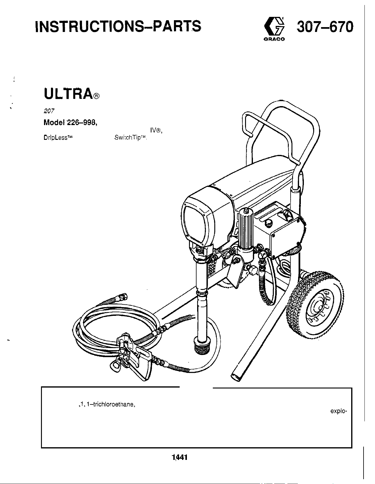
ULTRA@
207
bar
Model.226-998, Series
Complete sprayer with hose, gun, RAC
DripLessTM Tip Guard and SwitchTipTM.
U.S.
PATENT NO. 4,323,741, 4,397,610
PATENTED 1983, CANADA
AND OTHER PATENTS PENDING
NOTE: See Index on page
230
VAC
MAXIMUM
WORKING PRESSURE
433
E
2
AIRLESS PAINT SPRAYER
lV@,
n
.
Hazard
Never use 1 ,1, 1-trichloroethane, methylene chloride, other halogenated hydrocarbon solvents or fluidscontaining
such solvents in this equipment. Such
sion, which could cause death, serious bodily injury and/or substantial property damage.
Consult your fluid suppliers to ensure that the fluids being used are compatible with aluminum and zinc parts.
Refer to the Technical Data on page 43 for more information.
of
Using
Fluids
GRACO INC. P.O.
Containing Halogenated Hydrocarbons
use
could result in a serious chemical reaction, with the possibility of explo-
BOX
COPYRIGHT 1983, GRACO INC.
WARNING
1:Ml
MINNEAPOLIS, MN
55440-1444
Page 2
TABLE
OF
CONTENTS
Introduction 2
Warnings 4
Setup
Operation
Shutdown
Flushing Guidelines
Troubleshooting Guide
Motor Won't Operate
Low Output
No
Excessive Pressure Fluctuations
Motor
Electrical Short
SpinTest
BridgeTest
Repair
List of Tools
General Repair Notes
Power Supply Cord Replacement
Filter Replacement
ON/OFF Switch Replacement
Microswitch Replacement
...............................
.................................
....................................
.................................
&
Care
.........................
.......................
....................
............................
Output
.............................
...........
Is
Hot and Runs Intermittently
........
.........................
.............................
............................
...........................
...................
........
-
.
......................
.............
................
6
8
10
11
13
16
17
17
18
18
19
20
21
21
22
22
23
23
INTRODUCTION
ULTRA@
Your new Ultra@ 433 Sprayer functions and operates dif
ferently than other airless paint sprayers. This section will
help you become familiar with the sprayer before operat
ing it.
Pressure Control
The pressure control includes an
sprayer, the pressure adjusting control knob and a pres
sure sensing device. Its function is to control the motor
speed
sure at the pump outlet.
Motor
The DC motor has sealed bearings and replaceable
tor brushes. Its function is to drive the displacement
pump at the rate needed to supply sufficient paint volume
at the selected pressure. Working together, the pressure
control and motor cause the pump to cycle whenever
there is fluid or pressure demand. When the pump is cy
cling, the motor sounds like an automobile starter crank
ing. When the pump
intermittently until the fluid pressure stabilizes, then the
motor will shut itself
to the sprayer and it will stay pressurized and ready to
use
unless you manually shut it off and relieve pressure.
433
BASIC COMPONENTS
ONlOFF switch for the
so
that the sprayer maintains constant fluid pres
is
not cycling, the motor may hum
off.
However, there will stili be power
-
-
-
-
mo-
-
-
Bridge.Rectifier Replacement
Choke Replacement
Varistor Replacement
Circuit Board Replacement
Pressure Control Replacement
Pressure Control Calibration
Bearing Housing
Conn. Rod
Drive Housing
Motor Brush Replacement
Capacitor Replacement
Motor Replacement
Parts Lists and Drawings
Complete Sprayer
Pressure Control Assembly
NOTE:
Accessories 42
Technical Data 43
Dimen.sions.. 43
Warranty Back Cover
Fluid Filter
The fluid filter strains the paint to help avoid clogs in the
hose and spray tip. The filter includes a reusable element
and a pressure drain valve for relieving fluid pressure.
Hoses
The grounded, nylon spray hoses have spring guards on
both ends.
3/16 in.
nylon hose material acts as a pulsation dampener to ab
sorb pressure fluctuations.
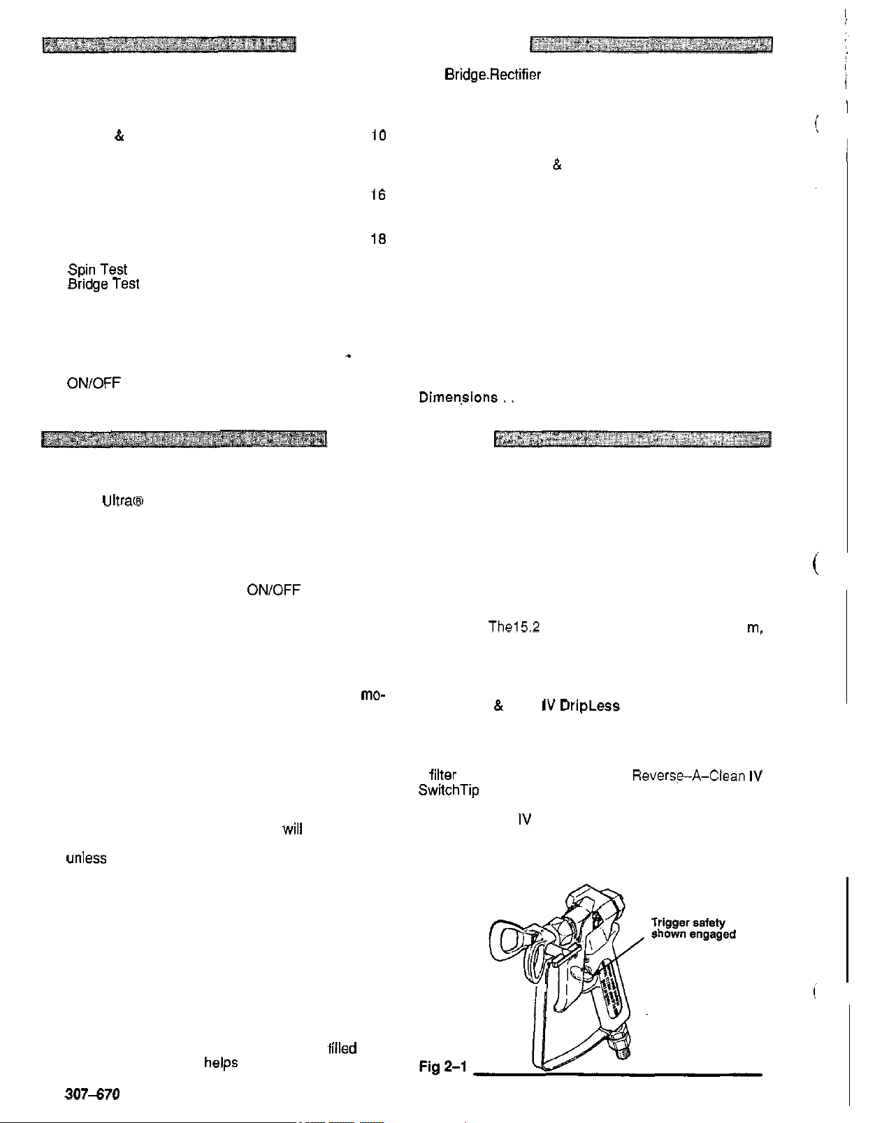
Spray Gun
Graco high pressure spray guns have a trigger safety
which prevents accidental triggering when it
See
a
SwitchTip uses high pressure fluid to remove clogs from
the spray tip without removing
verse
which helps reduce the risk of fluid injection injury.
See manual 307-793, supplied, for the displace
ment pump repair instructions and parts list.
.........................
The152 m hose has a 1/4 in.
ID
whip hose allows flexible gun movement. The
&
Fig Z-I.
filter for final paint straining. The ReverseA-Clean IV
-A-
Clean IV DripLess tip guard is a safety feature
Replacement 32
..............................
.............................
.............................
RAC
The gun provided with the sprayer also has
.....................
....................
&
Replacement, 30
...................... 35
.......................
IV
DripLess Tip Guard
..............
................
.............
...............
24
25
25
26
27
28
..............
...............
.................
...................
................
ID.
The
is
engaged.
it
from the gun. The Re
0.9
33
34
38
40
m,
-
-
-
Because the motor is DC, it
age or voltage fluctuations than an AC motor, and an ex
tension cord of up to 45 m can be used.
Drive Assembly
The sealed drive assembly transfers power from the DC
motor to the displacement pump.
Displacement Pump
The positive displacement, volume
vides equal fluid delivery on both the up and down pump
strokes. The pump has a wet
Graco Throat Seal Liquid,
throat packings and piston rod.
2
307-670
is
less sensitive to low volt
-
balanced pump pro-
-
cup which, when filled with
helps prevent damage to the
-
-
Page 3

Fig
3-1
\
CONTRACTOR GUN
WlTH
RAC
517 SIZE
'
IV
DRIPLESS
SWITCHTIP
WHIP
END HOSE
TIP
GUARD
AND
307470 3
Page 4
HIGH
FOR
Read and understand
PRESSURE SPRAY CAN CAUSE SERIOUS INJURY.
PROFESSIONAL USE ONLY. OBSERVE ALL WARNINGS
all
instruction manuals before operating equipment.
FLUID INJECTION HAZARD
General
This equipment generates very high fluid pressure. Spray from
the gun, leaks or ruptured components can inject fluid through gun safety latch in the closed or"safe"position, making the gun
yourskin and into your body and causeextremelyserious bodily inoperative. Failure
injury, including the need for amputation. Also, fluid injected or tal triggering of the gun.
splashed into the eyes or on the skin can cause serious dam
age.
NEVER pointthespray gunat anyoneorat any partofthe body,
NEVER put hand or fingers Over the spray tip. NEVER
"
blow back" paint; this is NOT an air spray system.
ALWAYS have the tip guard in place
spraying. the gun.
ALWAYSfollow the Pressure Relief Procedure,
cleaning or removing the spray tip or servicing any system
NEVER
Be sure equipment safety devices are operating properly before
each use.
Medical
. . . - -. - -.
If
any fluid appears
MEDICAL
CUT.
Note to Physician: Injection in the skin is a traumatic inju
important to treat the injury surgically as
not
with some exotic coatinos iniected directlv into the blood
stream. Consultation with
hand surgeon may be advisable.
Spray
Be sure all gun safety devices are operating properly before
each use. Do
cause a malfunction and result in serious bodily injury.
Safety
on
the spray gun when gunfirmlytothepail.
below;
try
to'stop or deflect leaks with your hand or body.
Alert-Airless Sarav Wounds
. .
.
-. . . . . . .
CARE
Tell the doctor exactly what fluid was injected.
delay treatment to research toxicity. Toxicity
Gun
Safety Devices
not
.
- -
to
AT ONCE.
remove or modify any part of the gun; this can
-,-~-,
penetrate your skin. get
DO
-
a plistic surgeon br reconstructive
NOT
~ ~~~~~~
TREAT
soon
EMERGENCY
AS
as possibr. Do
is
try
before
A
SIMPLE
It is
a concern
to
Safety
Wheneveryoustopspraying,evenforamoment,
-
Latch
to
set the safety latch can result in acciden
Diffuser
The gun diffuser breaks up spray and reduces the risk of fluid
injection when the tip is not installed. Check diffuser operation
regularly. Follow the Pressure Relief Procedure, below, then
remove the spray tip. Aim the gun into a metal pail, holding the
If
the fluid emitted is not diffused into an irregular
stream*
Tio
ALWAYS have the tip guard in place
spraying. The tip guard alerts you
and helps reduce, but does not prevent, the risk of accidentally
placing your fingers or any part of your body close
tip.
Trigger
Always have the trigger guard in place
ing
dropped or bumped.
Spray
Use extreme caution when cleaning or changing spray tips.
the spray tip clogs while spraying. engage the gun safety latch
immediately. ALWAYS foilow the Pressure Relief Procedure
and then remove the spray tip to clean
NEVER wipe
fully relieved and the gun safety latch is engaged.
replace
Guard
.~
~ ~
Guard
to
reduce the risk of accidentally triggering the gun
Tip Safety
Usingthelowestpossiblepressure,trigger
the
diffuser
off
buiid-up around the spray tip until pressure is
immediately'
to
the fluid injection hazard
on
the spray gun while
on
the gun when spray
it.
alwayssetthe
to
the spray
if
it
is
-
-
If
i
,
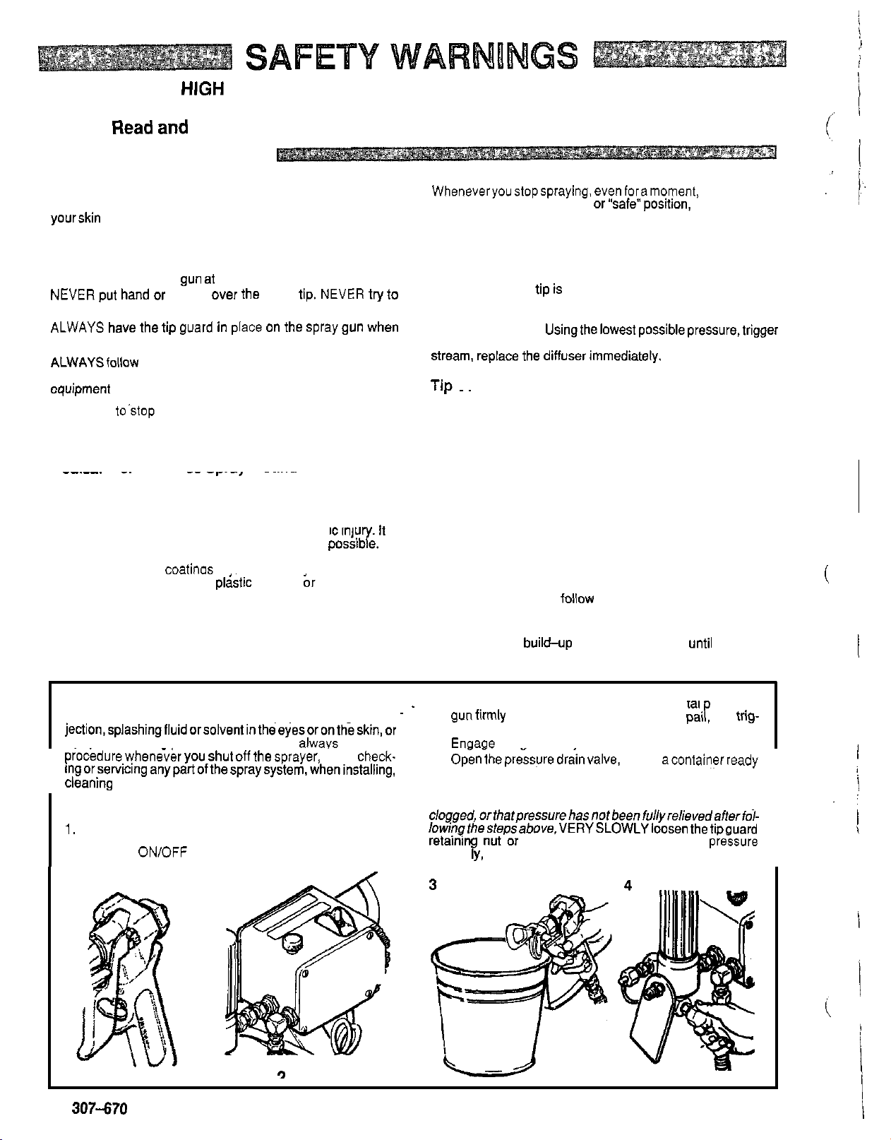
Pressure Relief
To reduce the risk of serious bodily injury, including fluid in
jection,splashingfluidorsolventintheeyesorontheskin,or
injury from moving Darts or electric shock, always follow this
procedure whenever
ingorservicinganypartofthespraysystem,wheninstalling,
cleaning
I
spraying.
1.
2.
4
307-670
or
Engage the gun safety latch.
Turn the ON/OFF switch
I
Procedure
YOU
shut
Off
the sprayer, when check-
changing spray tips, and whenever you stop
to
OFF,
9
3.
-
~
Disengage the gun safety latch. Hold a metal art of the
'
. gun firmly to the side of a grounded metal pair and trig-
ger the gun
4.
Enoage the aun safetv latch.
5.
OGnihepre&uredra-invalve,
to catch the drainage. Leave the valve
ready
If
you
suspect that the spray tip or hose
clogged,orthatpressurehasnotbeenful~relievedafterfol-
lowinqthestepsabove,VERYSLOWLYloosenthetiDauard
retai6n nut'or hose end coupling and relieve pi&sure
gradual
9
y,
to
relieve pressure.
having acontainerready
open
to
spray again.
then loosen completely. Now clear the tip or hose.
until you are
is
completely
I
I
I
Page 5
MOVING PARTS HAZARD
Moving parts can pinch or amputate your fingers or other body
pans. KEEP CLEAR of moving parts when starting or operating
the sprayer. Follow the Pressure Relief Procedure on page
beforechecking or servicing any part ofthe sprayer,
from starting accidentally.
to
prevent it
4
EQUIPMENT MISUSE HAZARD
General
Anv misuse of
ovirpressurizing, modi$ing'parts. using incompatible chemi
cals and fluids, or using worn or damaged parts, can cause
them
oron the skin, or other serious bodily injury, or fire, explosion or
property damage.
NEVER alter or modify any part of this equipment; doing
could cause it
CHECK all spray equipment regularly and repair or replace
worn or damaged parts immediately.
Always wear protective
tor as recommended by the fluid and solvent manufacturer.
S
Tlis sDraver can develoo
PRESSURE. Be sure that
used are rated
maximum working pressure of anv component or accessory
used in the system.
Fluid
BE
patible with the wetted parts shown in
on page
literature before using them in this sprayer.
Safet
t
1
e spray eauipment or accessories, such as
to
rupture and result in fluid injection, splashing in the eyes
to
malfunction.
-.
eyewear, gloves, clothing and respira
stem
Pressure
to
withstand this pressure.
and
SURE
Solvent Compatibility
that all fluids and solvents used are chemically com-
43.
Always read the fluid and solvent manufacturer's
207
all
bar MAXIMUM WORKING
spray equipment and accessories
DO
NOT exceed the
theTECHNlCAL DATA
so
HOSE SAFETY
High pressure fluid
hose develops a leak, split or rupture due
damage or misuse, the high pressure spray emitted from it can
cause a fluid injection injury or other serious bodily injury or
property damage.
ALL FLUID HOSES MUST HAVE SPRING GUARDS ON
BOTH
ENDS! The spring guards help protect the hose from
kinks or bends at or close
hose rupture.
TIGHTEN all
pressure fluid can dislodge a
sure spray
NEVER use a damaged hose. Before each use, check the en
tire hose for cuts, leaks, abrasion. bulging cover, or damage or
movement
ist, replace the hose immediately.
pressure hose or mend it with tape or any other device.
paired hose cannot contain the high pressure fluid.
HANDLE AND ROUTE HOSES CAREFULLY.
hoses
and hot surfaces of the pump and gas engine.
-
or solvents which are
coverofthe hose.
above
Hose
Proper hose grounding continuity is essential
groundedspriy system. Checkthe electrical resistanceof your
fluid hoses at least once a week.
tag on it which specifies the maximum electrical resistance,
conlact the hose supplier or manufacturer for the maximum re
sistance limits. Use a resistance meter in the appropriate range
for your hose
the recommended limits, replace it immediately. An un
grounded or poorly grounded hose can make your system haz
ardous.
lo
of
to
move equipment. Keep hoses clear of moving paris
62"
C or below -40' C.
Grounding
Also
in
the hoses can be very dangerous.
to
the coupling which can result in
fluid connections securely before each use. High
be emitted from the coupling.
the hose couplings.
loose coupling or allow high pres
If
DO
to
any kind of wear,
any of these conditions ex
NOT try
to
Do
not
DO NOTexposeGraco hosetotemperatures
compatible with the inner tube and
Do
Continuity
to
If
your hose does not have
to
check the resistance.
read FIRE
OR
EXPLOSION HAZARD.
If
the resistance exceeds
If
the
recouple high
no1 use fluids
maintaining a
A
re-
not pull on
a
-
-
-
-
-
-
FIRE OR EXPLOSION HAZARD
2.
Fluid
Static electricity is created by the flow of fluid through the pump
and hose.
grounded, sparking may occur, and the system may become
hazardous. Sparking may also occur when plugging in or
plugging a power supply cord or using a gasoline engine.
Sparks can ignite fumes from solvents and the fluid being
sprayed, dust particles and other flammable substances,
whether you are spraying indoors or outdoors, and can cause a
fireorexplosionandseriousbodilyinjuryandpropertydamage.
If
you experience any static sparking or even a slight shock
while using this equipment,
ATELY. Check the entire svstem for orooeroroundina.
use the system again until
corrected.
If
every pari of the spray equipment is not properly
STOP
the problem has b>en idenzfied and
SPRAYING IMMEDI-
Do
un-
not
Grounding
To reduce the risk of static sparking, ground the sprayer and all
other spray equipment used or located in the spray area.
CHECKyourlocalelectricalcodefordetailedgroundinginstruc-
tions for your area and type of equipment. BE SURE
all of this spray equipment:
1.
Sprayecconnect a ground wire and clamp (supplied)
true earth ground.
to
ground
to
a
3.
4.
5.
6.
7.
Flushing
Reduce the risk of fluid injection injury, static sparking, or
splashing by following the flushing procedure given on page 11
&
page
partofthegunfirmlytothesideofagroundedmetalpailanduse
the lowest possible fluid pressure during flushing.
hoses:use only grounded hoses with a maximum of
150 m combined hose length
ity. See Hose Grounding Continuity.
Spraygun: obtain grounding through connection
erly grounded fluid hose and sprayer.
Object
being
sprayed: according
Fluid
supply container: according
All solvent pails used when flushing, according
code. Use only metal pails, which are conductive. Do not
place the pail on a non
or cardboard, which interrupts the grounding continuity.
To
maintain grounding continuity when flushing orrelieving
pressure, always hold a metal part of the gun firmly
side of a grounded
Safety
12 of this manual. Follow the Pressure Relief Procedure
4.
and remove the spray tip before flushing. Hold a metal
metal pail, then trigger the gun.
to
ensure grounding continu-
to
a prop
to
local code.
to
local code.
to
local
-
conductive surface, such as paper
to
the
on
IMPORTANT
United States Government safety standards have been adopted under the Occupational Safety and Health Act. These standards-
particularly the General Standards, Part 1910, and the Construction Standards, Part 1926 - should be consulted.
-
307-670
5
Page 6
1.
Connect Hose and Gun.
Refer
to
Fig
SETUP
6-1
NOTE:
2.
When tightening fittings at the pressure control,
hold one wrench firmly on the hex of the pressure
control fitting to keep it from rotating. Use an
other wrench to tighten the mating fitting.
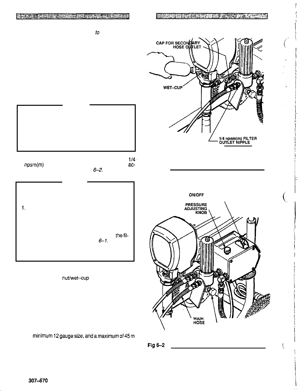
a. Remove the cap from the filter outlet nipple and
screw the
b. Connect the whip hose between the fluid hose
and the gun inlet connection.
c. Don't use thread sealant, and don't install the
spray tip yet!
If you are supplying your own hoses and spray
gun, be sure the hoses are electrically conduc
tive, that the gun has a tip guard and that each
part is rated for at least
sure. This is to reduce the risk of serious bodily
injury caused by static sparking, fluid injection or
over
-
pressurization and rupture of the hose or
gun.
Two Gun Hookup.
npsm(m) nipple - See
cessory hose and gun. See
To
avoid damaging the pressure control, which
may result in poor equipment performance and
component damage, follow these precautions:
1.
Always use nylon spray hose at least
long.
15.2
m main
WARNING
CAUTION
fluid
hose onto the nipple.
207
bar
Working
Remove the cap from the
Fig
6-1
-
and attach an ac-
Fig
6-2.
Pres
15.2
-
-
m
-
1/4.
Fig
6-1
ON/OFF SWITCH
DO NOT INSTALL ANY
SHUTOFF DEVICE
HERE
\
2.
Never use a wire braid hose as it is
act
as
a pulsation dampener.
3.
Never install any shutoff device between thefil-
ter and the main hose. See
4.
Always use the main filter outlet for one gun op
eration. Never plug this outlet.
3. Fill Packing Nutwet-Cup.
Fill the packing nut/wet-cup
Throat Seal Liquid (TSL), supplied.
4.
Check the Electrical Service
a. Be sure the electrical service is properly rated for
your sprayer and that the outlet you use is prop
erly grounded.
b. Have a licensed electrician attach an appropri
ate plug
c. Use an extension cord which has
minimum12gaugesize,andamaximumof45m
long. Longer lengths may affect sprayer per
formance.
to
the power supply cord.
Fig
See
1/3
6-1.
Fig
full
too
6-1
with Graco
3
wires of a
rigid to
-
-
...
^.
.
-
\
SECONDARY HOSE
-
.
HOSE
'
PRESSURE
DRAIN VALVE
6
307-670
Page 7
5.
Plug
in
the Sprayer.
OFF.
Then plug the cord into a grounded electrical
outlet at least
6
Be sure the
ONlOFF
m away from the spray area.
WARNING
Proper electrical grounding is essential
to
reduce
the risk of fire or explosion which can result in seri-
ous
bodily injury and property damage. Refertothe
warning section
FIRE
OR
EXPLOSION HAZARD
on page 5 for more detailed grounding instructions.
f
6.
Flush the pump
was left in
to
a. Before using water
to remove the lightweight oil which
protect pump parts after factory testing.
-
base paint, flush with min
eral spirits followed by soapy water, and then a
clean water flush.
b. Before using oil
spirits only.
c. See
FLUSHING GUIDELINES
-
base paint, flush with mineral
-.
on page
for the flushing procedure.
SETUP
switch is
11
&
12
7.
Prepare the
paint
according
to
the manufacturer's
recommendations.
a. Remove any skin that may have formed.
b. Stir the paint
to
mix pigments.
c.. Strain the paint through a fine nylon mesh bag
(available at most paint dealers)
to
remove parti
cles that could clog the filter or spray tip. This is
probably the most important step toward
trouble
-
free spray painting.
I
-
307470
7
Page 8
'(
OPERATION
WARNING
Pressure Relief Procedure
To
reduce the risk of serious bodily injury, including
fluid injection, splashing fluid or solvent in the eyes
or on the skin, or injury from moving parts or electric
shock, always follow this procedure whenever you
shut off the sprayer, when checking or servicing
any part of the spray system, when installing,
cleaning or changing spray tips, and whenever you
stop spraying.
1.
Engage the gun safety latch.
2.
Turn the ONlOFF switch
3. Disengage the gun safety latch.
part of the gun firmly
metal pail, and trigger the gun
sure.
4. Engage the gun safety latch,
5.
Open the pressure drain valve, having a con
tainer ready
valve open until you are ready
lf you suspect
pletely clogged,
relievedaffer following
around the tip guard retaining nut or hose end cou-
pling and VERY SLOWLY loosen the part
lieve pressure gradually, then loosen completely.
Now clear the tip or hose.
to
catch the drainage. Leave the
that
the spray
or
that
to
OFF.
Hold a metal
to
the side of a grounded
to
relieve pres
to
spray again.
tip
or
hose
pressure
the
has
not been fully
steps above,
wrap a rag
is
*
com
to
re
-
-
-
-
the
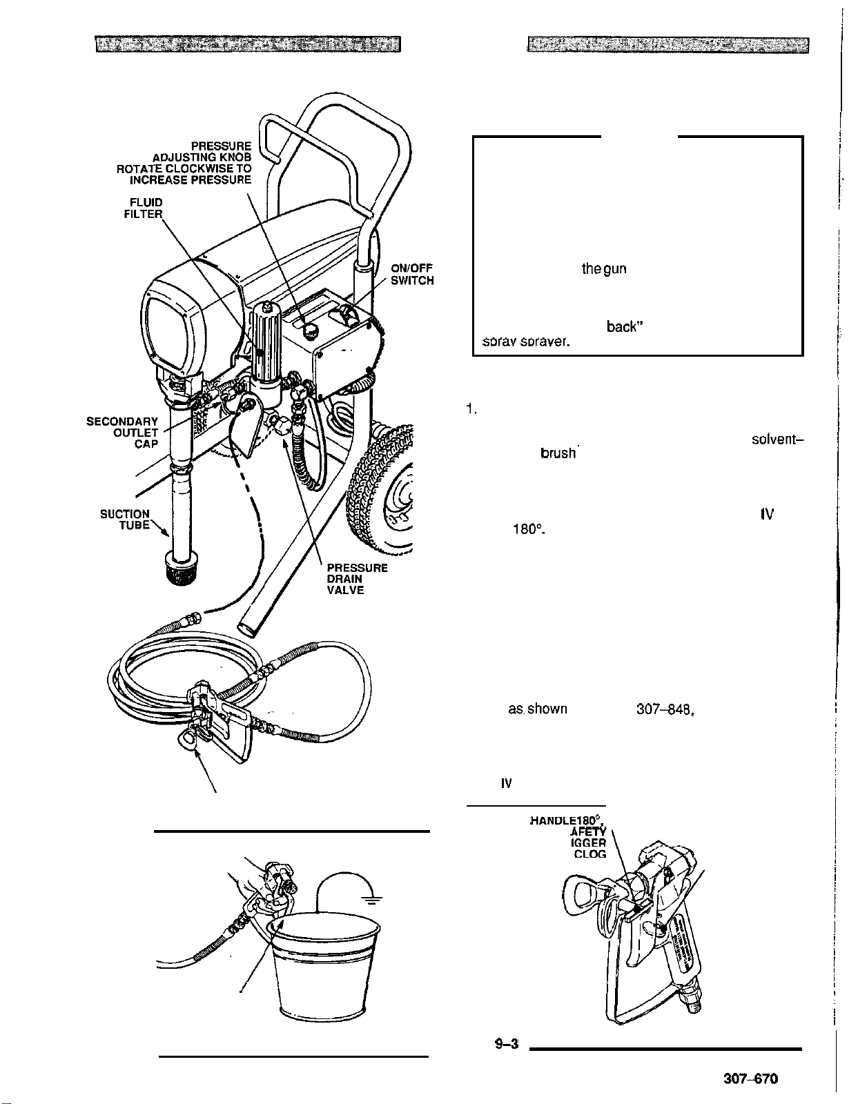
3. Put the suction tube into
4.
Lower the pressure setting
adjusting knob all the way counterclockwise. See
9-1.
5.
Disengage the gun safety latch.
6.
To prime the pump,
firmly against and aimed into a metal waste con
tainer.
open, turn the
crease the pressure setting until the sprayer starts.
Keep the gun triggered until all air is forced
system and the paint flows freely from the gun. Re
lease the trigger and engage the gun safety latch.
NOTE:
7. Check all fluid connections for leaks.
found, follow the
ing, to
8.
Install the Spray Tip and Tip Guard.
gun safety latch is engaged. See
spray tip.
ual307-848, supplied with the gun, for installation in-
structions.
9.
Adjust the Spray Pattern
See
Fig
9-2.
ON/OFF switch
If the pump is hard
under the pressure drain valve and open it.
When fluid comes from the valve, close it. Then
disengage the gun safety latch and proceed as in
Step
6,
above.
the left, before tightening connections.
If
using the
hold a metal part of the gun
Squeeze the trigger and hold it
to
Pressure Relief Procedure Warn
RAC
paint container.
by turning the pressure
See
Fig
to
ON, and slowly in
prime, place a container
If
Be sure the
Fig
9-3.
install the
IV tip guard, refer
9-3.
out
of the
any are
to
man-
Fig
-
-
i
i
i!
-
-
Startup
Use this procedure each time
help ensure the sprayer is ready
start it safely.
NOTE:
1.
2.
For the first time startup, be sure
sprayer first. See page
GUIDELINES.
Close the pressure drain valve.
stalled a secondary hose, be sure the nipple is firmly
plugged with the cap.
Don't install the spray tip yet!
.'
you
to
11
See Fig
start the sDraver
operate and that you
to
&
12
for
FLUSHING
If you have not in
9-1.
to
flush the
a. Increase the pressure adjusting knob setting just
until spray from the gun is completely atomized.
To avoid excessive overspray and fogging, and
to
decrease tip wear and extend the life of the
sprayer, always use the lowest possible pres
sure needed
b. If more coverage is needed, use a larger tip
rather than increasing the pressure.
c. Test the spray pattern. TO adjust the direction of
-
the spray pattern, engage the gun safety latch
and loosen the retaining nut. Position the tip
guard horizontally for a horizontal pattern or ver-
tically for a vertical pattern. Then tighten the re
taining nut.
to
get the desired results.
-
-
8
307-670
Page 9
OPERATION
Cleaning a Clogged
Tip
WARNING
To reduce the risk of serious bodily injury from fluid
injection:
NEVER operate the spray gun with thetipguard re
moved.
DO
NOT hold your hand, body, or a rag in front of
the spray tip when cleaning or checking a clogged
tip. Always point
waste container when checking to see
thegun toward the ground or into a
if
the tip is
clear.
DO NOT
try
to "blow back" paint: this is NOT an air
mrav sDraver.
1.
Clean the front of the tip frequently during the day's
operation. First, follow the
dure Warning
soaked
brush^
on page 8. Then use a solvent-
to wipe-away fluid build-up, which
Pressure Relief Proce
helps prevent tip clogging.
-
-
Fig
9-1
NEVER OPERATE THE GUN
WITH THE TIP GUARD
REMOVED
2.
If the spray tip does clog, release the gun trigger, en
gage the gun safety latch, and rotate the RAC
dle
180".
See
Fig
9-3.
3.
Disengage the gun safety latch and trigger the gun
IV
han
into a waste container. Engage the gun safety latch
again.
4. Return the handle to the original position, disengage
the gun safety latch, and resume spraying,
5.
If the tip is still clogged, engage the gun safety latch,
shutoff and unplug the sprayer, and open the pres
sure drain valve to relieve pressure. Clean the spray
tip as.shown in manual 307-848, supplied with the
RAC IV.
RAC
IV
HANDLE SHOWN
IN SPRAYING POSITION,
HANDLElBO",
TURN
DISENGAGES
LATCH AND TR
GUN
TO
CLEAR
GUN
SAFETY
LATCH
SHOWN EN.
GAGED
-
-
-
MAINTAIN FIRM
METAL TO METAL
CONTACT WHEN
Fig
9-2
FLUSHING
1
Fig
9-3
307-670
9
Page 10
~~~
SHUTDOWN AND CARE
WARNING
To reduce the risk of serious bodily injury, including
on
fluid injection or splashing in the eyes or
or injury from moving parts, always follow the
sure Relief Procedure Warning
on page
checking, adjusting, cleaning and shutting down the
sprayer.
1
.
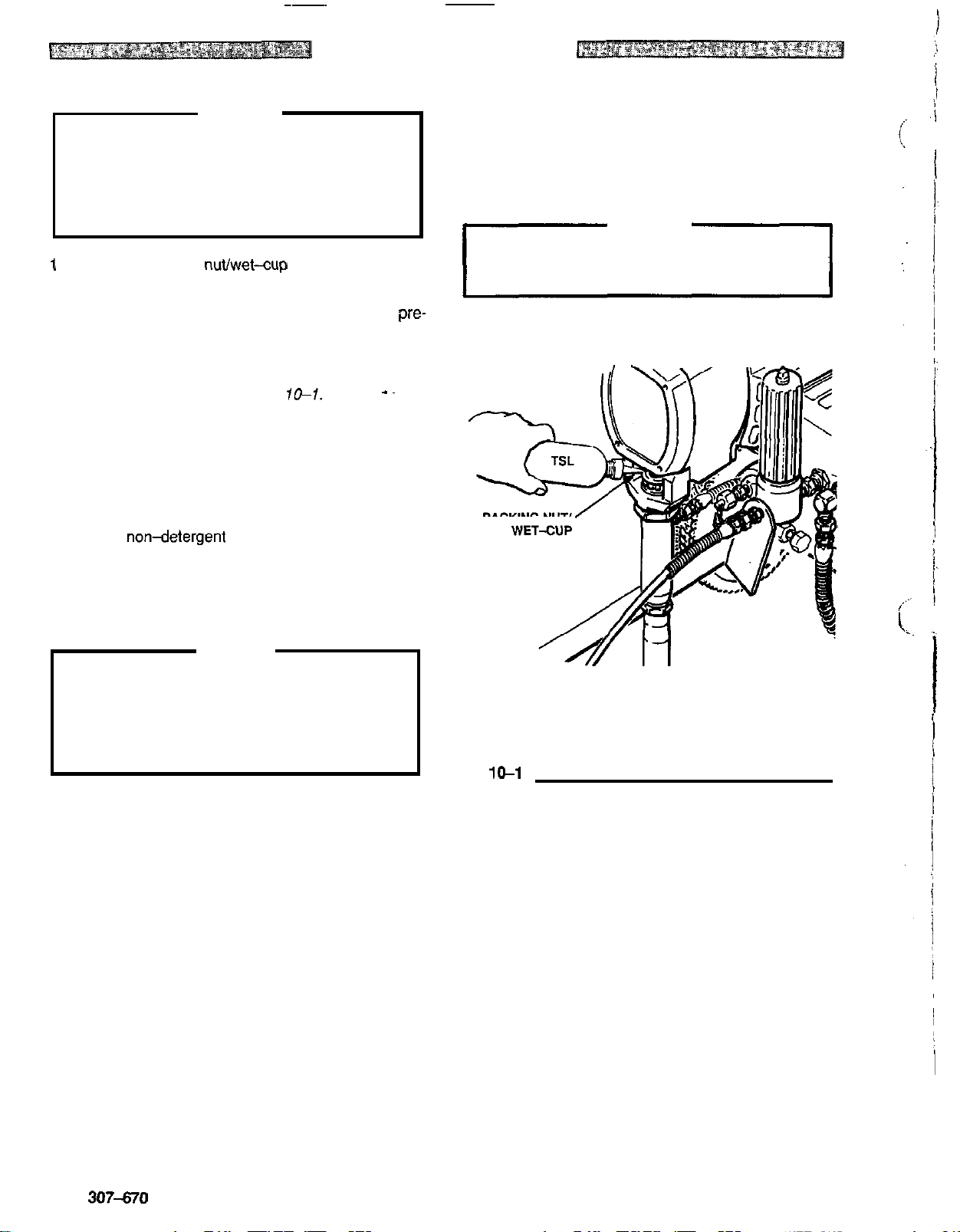
Check the packing nuvwet-cup daily. First follow the
Pressure Relief Procedure Warning
Be sure the wet-cup is 1/3 full of TSL at all times
help prevent fluid buildup
mature wear
tight enough
of packings. The packing
to
stop leakage, but no tighter. Over
on
the piston rod and pre-
tightening may cause binding and excessive packing
wear. Use a round punch or brass rod and light ham
mer
to
adjust the nut. See
Fig
10-1.
2. Clean the fluid filter often and whenever the sprayer
is stored. First follow the
dure Warning
307
-
273, supplied, for the cleaning procedure.
on
Pressure Relief Proce
page 11. Refer
the skin,
Pres
-
11
before
on page
11.
to
nut should be
-~
to
manual
__
5.
For very short shutoff periods, leave the suction tube
in the paint, follow the
Warning
6.
Coil the hose and hang it
on page 11, and clean the spray tip.
ing it, even for overnight,
Pressure Relief Procedure
on
the hose rack when stor
to
help protect the hose
-
from kinking, abrasion, coupling damage, etc.
WARNING
Refer
to
the warning section
page 5 for information on the hazard
HOSE SAFETY
of
using dam
on
-
aged hoses.
-
-
3. Lubricate the bearing housing after every 100 hours
of operation. Fill the connecting rod cavity with
No.
10 non-detergent oil.
4.
Flush the sprayer at the end of each work day and
it with mineral spirits
and freezing. See
page
11.
'To
prevent pump corrosion, and
chance of fluid freezing in the pump
to
help prevent pump corrosion
FLUSHING GUIDELINES
CAUTION
to
reduce the
or
pressure con
SAE
fill
on
trol in cold weather, never leave water or any type of
paint in the sprayer when it is
can seriously damage the sprayer or result in a
not
in use. Freezing
loss
of pressure or stalling.
I
I
PACKING
Fig
10-1
NUT/
10
307-670
Page 11
FLUSHING GUIDELINES
Pressure Relief Procedure
To reduce the risk of serious bodily injury, including
fluid injection, splashing fluid or solvent in the eyes or
on the skin, or injury from moving parts or electric
shock, always follow this procedure whenever you
shut off the sprayer, when checking or servicing any
part of the spray system, when installing, cleaning or
changing spray tips, and whenever you stop spraying.
1.
Engage the gun safety latch.
2.
Turn the ON/OFF switch to
3.
Disengage the gun safety latch. Hold a metal part
of the gun firmly to the side of a grounded metal
pail, and trigger the gun to relieve pressure.
OFF,
4.
Engage the gun safety latch.
5.
Open the pressure drain valve, having acontainer
ready to catch the drainage. Leave the valve open
until you are ready to spray again.
If
you
suspect that the spray tip or hose
clogged, or that pressure
has
not
been
is
completely
fully
relieved
after following the steps above, wrap a rag around the
tip guard retaining nut or hose end coupling and
VERY SLOWLY loosen the part to relieve pressure
gradually, then loosen completely. Now clear the tip or
hose obstruction.
1
1.
New Sprayer. Your new sprayer was factory tested
2
in lightweight oil which was left in to protect pump
parts.
Before using water
-
base paint, flush with mineral
spirits followed by soapy water, and then a clean
water flush.
Before
using
oil-basepaint, flush with mineral spirits
only.
2.
Changing Colors. Flush with a compatible solvent
such
as
3.
Changing
mineral spirits
from
or
water.
water-base
to
oil-base paint.
Flush with warm, soapy water, then mineral spirits.
4.
Changing
from
oil-base to water-base paint.
Flush with mineral spirits, followed by warm, soapy
water, then a clean water flush.
5.
Storage.
3
4
CAUTION
NEVER leave water in the sprayer
if
there
is
slightest chance it could freeze. Push the water out
with mineral spirits. Water left to freeze in the pressure control tube prevents the sprayer from being
started and causes serious damage to the pressure
control.
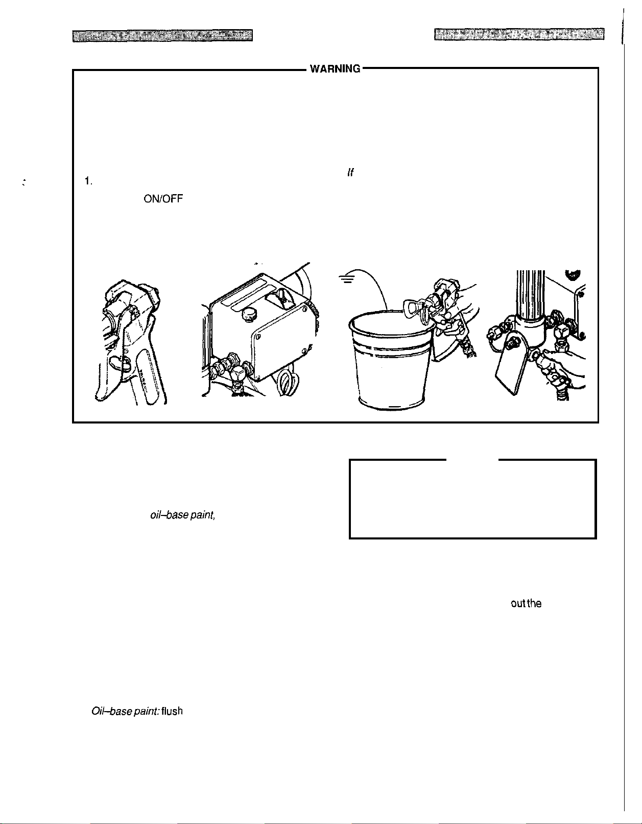
6.
Startup after storage.
-
Before using water
base paint, flush out mineral
spirits with soapy water and then a clean water flush.
When using oil
-
base paint, flush outthe mineral spir-
its with the paint to be sprayed and the sprayer
ready to use.
the
is
Water
-
base paint: flush with water, then mineral
spirits and leave the pump, hose and gun filled with
mineral spirits. Shut off the sprayer, open the pres
sure drain valve to relieve pressure and leave it open.
Oil-basepainttfiush with mineral spirits. Shut
off
the
sprayer, open the pressure drain valve to relieve
pressure and leave
it
open.
-
Continued on page
12.
307-670
11
Page 12
~
How
to
Flush
~~
~~
FLUSHING GUIDELINES
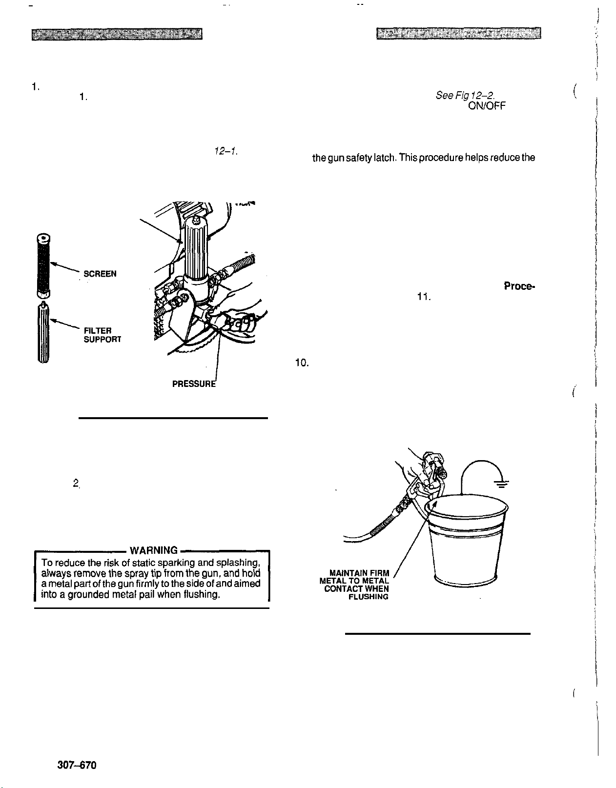
1.
Follow the
page
2.
If
the sprayer has been used before, remove the filter
bowl and screen: see manual 307
Pressure Relief Procedure Warning
1
1.
-
273, supplied.
Clean the screen separately and install the bowl
without the screen to flush
FILTER
BOWL
it.
See
Fig
PRESSUR*
DRAIN VALVE
12-1.
on
7. Hold a metal part of the gun firmly against and aimed
into a metal wastecontainer.
the trigger and hold
to
ON,
and slowly increase the pressure setting until
it
open, turn the
SeeFig
12-2.
Squeeze
ON/OFF
switch
the sprayer starts. Keep the gun triggered until all air
is forced out
of
the system and the solvent flows
freely from the gun. Release the trigger and engage
thegunsafetylatch.Thisprocedurehelpsreducethe
risk of static sparking and splashing.
NOTE:
If the pump is hard to prime, place a container
under the pressure drain valve and open it.
When fluid comes from the valve, close it. Then
disengage the gun safety latch and proceed as in
Step 7, above.
8.
Remove the suction tube from the pail. Disengage
the gun safety latch and trigger the gun
vent from the hose.
Do
not let the pump run dry for
to
force
sol
more than 30 seconds to avoid damaging the pump
packings! Then follow the
dure Warning
9.
Leave the pressure drain valve open until you are
on page
ready to use the sprayer again.
Pressure Relief Proce-
11.
If
the screen was re
moved, unscrew the filter bowl and reinstall the clean
screen. Reinstall the bowl, hand tight only.
IO.
If
you flushed with mineral spirits and are going to
use a water
lowed by a clean water flush. Then follow the
sure Relief Procedure Warning
-
base paint, flush with soapy water fol
Pres
on page
11.
-
-
(
-
-
i
Fig 12-1
3. Close the pressure drain valve.
4.
Pour
2.
liters of compatible solvent into a grounded
metal pail. Put the suction tube in the pail.
5.
Remove the spray tip from the gun,
6.
Lower the pressure setting by turning the pressure
if
it
is installed.
adjusting knob all the way counterclockwise.
Fig
12-2
12
307-670
Page 13
TROUBLESHOOTING
Pressure
To
reduce
fluid
the
alwaysfollowthisprocedurewhenever
sprayer,
sDrav
sprajl
1.
2.
3.
4.
Relief
the risk
iniection.
eyes
svstem.
tips,
Engage
Turn the
Unplug
Disengage the
or
on
when
and
the
the
th'e ikin,
ON/OFF
iniuw
checking
when
whenever
gun
power supply
Procedure
of
serious bodily injury,
from
solashina
moving
installing,
or
sewicing
park
cleanina
yoistop
safety latch.
switch to
cord.
gun
safety
latch. obstruction.
fluid
or
spraying.
OFF.
or
electric
you
any
or
WARNING
'5.
Hold
including
solvent
in
shock,
shut
off
part
the
of
the
changing ready
"
grounded
oressure.
6,
ingage
7.
Open
8.
Leave
ready to spray
lf
you
clogged,
ter
following
auard retainina nut
SLOWLY
ally,
then
GUIDE
a
metal
part
metal
the
gun
the
Pressure
to
catch the drainage.
the
pressure
suspect
that
orthatpressure
the steps
loo&&
loosen
the
completely.
of
pail,
safety
drain
drain
again.
the
spray
above,
or
hose
part
the
gun
firmly
to
and
trigger
the
latch.
valve, having
valve
open
tip
or
has
to
hose
notbeen
wrap a rag around the
end
relieve pressure
Now
fullyrelievedaf
coudina
clear the tip
the
side
gun
to
a
Container
until
you
is
complete/y
and
or
of
a
relieve
are
tip
VERY
gradu
hose
-
-
:heck everything
TYPE
OF
Basic Fluid Pressure
Problems
Basic Mechanical Problems
in
the
PROBLEM
guide
-
E
%ask Electrical Problems
before
disassembling
~ ~~
TO
WHAT
If
check
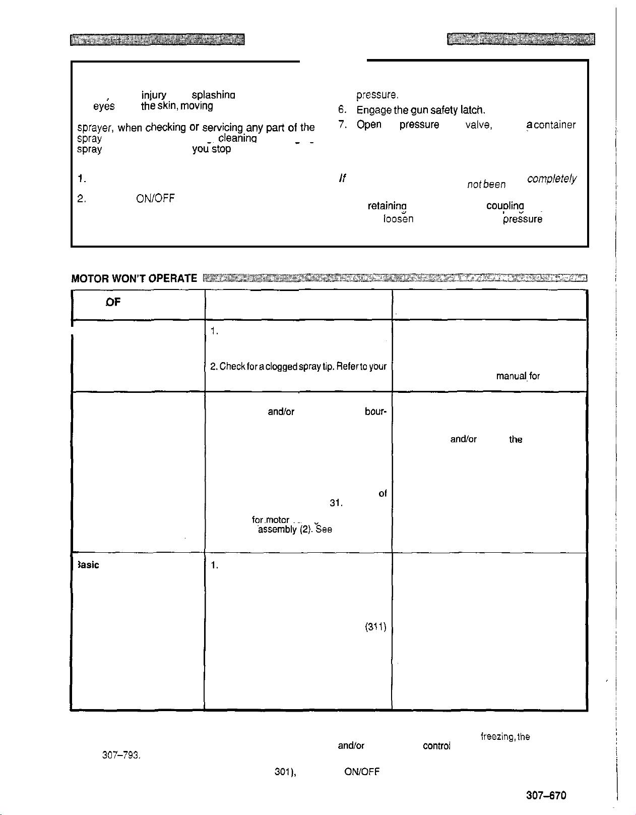
1.
Check the pressure control knob setting.
The motor
mum setting (fully counterclockwise).
2.Checkforacloggedspraytip.Refertoyour
separate gun or tip instruction manual.
1. Check for frozen or hardened paint in the
pump (39)
don tube. Using a screwdriver, carefully
try to rotate fan at back of motor by hand.
See page 19.
2.
Check displacement pump connecting
rod pin
into connecting rod
spring (35) should be firmly in groove
connecting rod. See page
3. Check for.motor damaae. Remove drive
housing
to rotate fan by hand.
1.
Check electrical supply with volt meter.
Meter should read 190
2.
Check extension cord for visible damage.
Use a volt meter or test lamp at extension
cord outlet to check.
3. Check sprayer power supply cord
for visible damage such as broken insula
tion or wires.
4.
Check motor brush leads. terminals and
brush length. Brush length should be
mm minimum. See page 33.
CHECK
is
OK,
will
andlor pressure control bour-
(20).
It must be completelypushed
assembly~(2). 3ee page
the
go
to
the next check.
not run
sprayer.
if
it
is at the mini
(3)
and retaining
31.
-
250 Volts.
32.
(3ql)
Try
14
WHAT
If
1.
-
2.
1.
2.
01
3. Replace motor
1. Reset building circuit breaker: replace
2.
3.
-
4.
TO
check
Slowly increase the pressure setting to
if
the motor starts.
Relieve pressure, refer to your separate
gun or tip instruction
ing.
Thaw. Plug in sprayer and turn
crease pressure setting to see
starts.
ment pump packings (see manual
307
control box (301). See page 27.
Push pin into place and secure with the re
taining spring.
building fuse. Try another electrical outlet.
Replace extension cord.
Replace power supply cord. See page
Tighten terminal screws; replace brushes.
See page 33.
DO
is
not
OK,
refer
to
this column.
manual.for tip clean
on.
If
it
doesn't, replace the displace
-
793) andlor replace the bare pressure
(1)
if
fan won't turn.
see
Slowly in
if
motor
22.
-
-
-
-
if
Thaw the sprayer
not try
to
start the sprayer until it has thawed completely.
If
operate.
manual
When replacing the bare pressure control box (item 301), remove the
and reinstall these parts in the bare box.
paint hardened (dried) in the sprayer, the pump packings andlor bare pressure control must bereplaced. See page
307-793.
water or water-based paint has frozen
in
it,
due to exposure to low temperatures, by placing it in a warm area.
If
the bourdon tube was not damaged by
OWOFF
the
freezing,the pump should
switch, bridge, circuit board and electrical hardware
27
Do
or
307-670 13
Page 14
‘YPE
OF
PROBLEM
WHAT TO CHECK
If
check
is
OK,
go
to the next check.
WHAT
If
TO
check is not
DO
OK,
refer to this column.
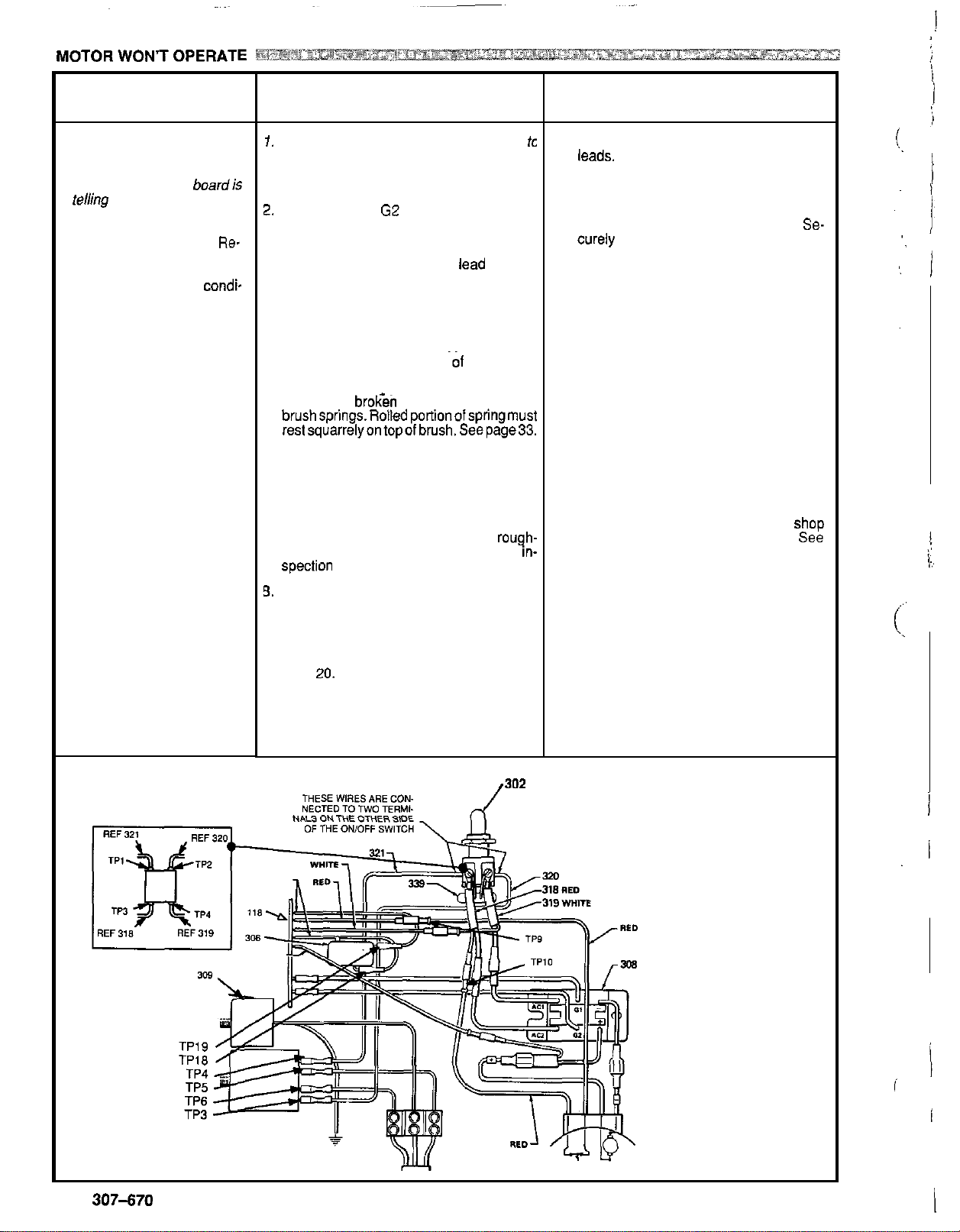
Diagnosing circuit board
indicator lamps. The nor
mal condition
clear lamp on when
telhg pump
Follow Pressure Relief
Procedure Warning.
move gun from hose. Re
move pressure control cover
and check for faulty
tion of circuit board lamps.
Condition
Both lamps on; pump
won’t operate and motor
is
not
is
to
A
running
red lamp on,
boardis
run.
Re-
condi-
1.
Check leads from bridge
be sure they are securely fastened ana
properly mated.
2.
Check
GI
and
circuit board (118) and bridge (308) for
damage or loose terminals.
-
3.
Check for loose motor brush lead connec
tions and terminals. See page 33.
4.
Checkbrush length which should be
minimum. See page 33.
NOTE:
same rate on both sides
Check both brushes.
5.
Check for brocen or misaligned motor
brushsprings.Rolledportionofspringmust
reslsquarrelyontopofbrush.Seepage33.
6.
Check motor brushes for binding in brush
holders. See page 33.
7.
Check motor armature commutator for
burn spots, gouges and extreme
ness. Remove motor cover and brush
spection plates
3.
Check motor armature for shorts using ar
mature tester (growler) or perform spin
test. See page 19.
3.
Check bridge (308) by substituting with a
good bridge or performing bridge test. See
page
CAUTION:
mature is determined to be good. A bad ar
mature
bridge.
The brushes do not wear at the
20.
Do
will
G2
to
not perform this check until ar
immediately burn out a good
(308)
connections between
of
check. See page 28.
to
motor tc
14
mm
the motor.
rough-
in-
1. Replace any loose terminals and crimp to
leads. Be sure male terminal blades are
straight and firmly connected to mating
part.
2.
Clean circuit board male terminals. Re
place loose or damaged terminals.
curely reconnect leads.
3. Tighten terminal screws. Replace
brushes
33.
4.
Replace brushes. See page 33.
5. Replace spring
with brush. See page 33.
6.
Clean brush holders. Remove carbon
with small cleaning brush.
leads with
free vertical brush movement.
7.
Remove motor and have motor ShOD
resurface commutator
page 35.
8. Replace motor. See page 35
-
9. Replace bridge. See page
-
-
if
leads are damaged. See page
if
broken. Realign spring
slot
in brush holder to assure
Align
if
possible. see
24
Se-
brush
-
!
WIRING DIAGRAM
14
307-670
I
302
Page 15

WPE
OF
PROBLEM
:ondition B (continued)
Both lamps
REFER
ING
off
TO
~
THE WIR-
-.
DIAGRA~J
PAGE 14 TO IDENTIFY
TP POINTS.
WHAT TO
If
check
1. Checkelectrical supply. Connectvoltmeter
to
190-250
2.
O
N
Check power supply
sprayer turned
TP1 and TP2. Meter should read 190-250
Volts.
CHECK
is
OK.
00
to the next check.
electrical outlet. Meter should read
Volts
to
ON.
See page 26.
circuit board with
Measure voltage at
WHAT TO
If
check
1.
Reset circuit breaker or replace outlet
is
DO
not
OK.
refer to this column.
fuse.lf circuit breaker or fuse continues
open, see "Electrical Short", page 18.
2. Unplug sprayer. Check continuity
polesofON/OFFswitch(302)fromTPlto
TP2 and
TP2
to
TP3. Replace switch
faulty.
of
to
both
if
:ondition
Red lamps
Clear lamp off
Unplug
C
on,
sprayer!
TP4 to TP6 and TP3
Check for any loose connections.
-.
3.
Check all terminals and wires for damage
or loose
4.
Checkmotorthermalcutoutswitch..Unplug
sprayer. Allow motor
motor thermal switch leads at
TP10. Use ohmmeter
fit.
to
cool. Disconnect
TP9 and
to
check continuity.
Switch should be closed when motor
3. Replace damaged terminals and recon
nect securely.
4.
close when motor is cool. See page 35.
is
cool.
5.
Check microswitch
pressure
in
the pressure control, discon
(306).
With no fluio
5.
nect wires TPlSandTP19. Checkcontinu-
ity across switch terminals with an ohmrne-
fer. Switch contact should be closed. De
press actuator button.
An
audible "clickin-
-
dicates the contacts have opened. Ohm-
6.
Check circuit board (118) by substituting
6. Replace circuit board. See page
with a aood board. See Daoe 26.
1.
Checkcircuit board
(1
18) by removing from
1. Replace circuit board. See page 26.
box withoutdisconnecting wires; see page
26 for removal procedure.
I
WARNING;
Removing the circuit board while still wired over-rides the
optical detector which could cause the sprayer to over
microswitch does
enough
to
check lamp condition, then shut off immediately.
WARNING:
~
only!
Do
not allow any metal objects
not
function properly. Turn the sprayer
To reduce the risk of electric shock, handle board by edges
to
come in contact with the board!
Check continuity of
RFI
filter (310) from
to TP5. Replace filter
if
faulty.
Check power supply cord (31 1) for
nuitv from TP5 to TP7 and TP6
Replace cord
Replace electric motor
if
faulty.
if
switch does
conti-
to
TP8.
not
Replace ihe microswitch. See page 23.
26.
-
pressurize,
on
if
the
ONLY long
-
on
Plug in and turn
should be
board over
ofi
and unplug the sprayer.
on
-
rides the optical detector.
2. Check bourdon tube flag and
sprayer. Clear lamp
now - removing the circuit
detectorposi-
tion. Reinstall circuit board (see page 26).
Turn pressure setting to maximum; flag
should extend less than half way into opti
cal detector
slot
from the bottom.
Turn
2. Calibrate pressure control to see
corrects problem. See page 28.
-
If
not, replace bare pressure control box
(301). See page
27.
307-670
if
that
15
Page 16

TYPE
OF
PROBLEM
TO
WHAT
If check
1.
Check for worn spray tip.
2. Check
tinue to stroke whbn gh trigger is re
leased. Plug in and turn on sprayer.
Primewith
ily, then release and engage safety
latch. Relieve pressure, turn
plug sprayer.
3. Check electrical supply with
Meter should read
4. Check extension cord size and length;
must be at least 12 gauge wire and no
longer than
5. Check
(308) to circuit board (1 18) for damage
or
page 26.
6.
Check stall pressure. Refer
tion Procedure on page 28.
7. Check bridge (308)
terminalstomotor. Inspect wiring insula
tion and terminals for signs of overheat
ing. See page 24.
8. Check for loose motor brush leads and
terminals. See page 33.
9.
Check for worn motor brushes which
should be 14 mm minimum. See page
33.
10.Checkfor broken and misaligned motor
brush springs. Rolled portion of spring
must rest squarely
11.Check motor brushes for binding in
brush holders. See page 33.
12.Checkcircuit board (1 18) by substituting
with a good circuit board. See page
13.Check motor armature for shorts by
ing an armature tester (growler) or per
form spin test. See page 19.
14,Checkbridge(308)bysubstitvtingwitha
good bridge or by performing the bridge
test. See page
CAUTION:
armature is determined
armature will immediately burn out a good
bridge.
CHECK
is
OK,
go to the next check.
to
see that Dum0 does
paint.Triggergun momentar
190-250
15,2 m .
G1
and G2 leads from bridge
loose
wires or connectors. Refer
+
on
top of brush.
20
or 24.
Do
not perform this check until
to
not
con
off
and
un
volt
meter.
Volts.
to
to
Calibra
and - leads and
26.
us
be good. A bad
-
-
-
-
-
-
-
-
-
WHAT
If
1.
2. Service pump. See manual 307
3. Reset building circuit breaker; replace
4. Replace with a correct, grounded exten
5. Clean circuit board male terminals. Re
6.
7.
8. Tighten terminal screws. Replace
9. Replace brushes. See page 33.
10.Replace spring
11.Clean brush holders, remove carbon
12.Replace circuit board.
13.Replace motor.
14.Replace bridge.
TO
check
Follow Pressure Relief Procedure
Warning then replace tip. See
separate gun or tip manual.
building fuse. Repair electrical
try
sion cord.
place loose or defective lead terminals.
Securely reconnect lead terminals to
board.
Calibrate pressure control. See page 28.
Be
tered and firmly connected
minals. Replace any
damaged wiring. Securely reconnect
wires to bridge.
brushes
33.
with brush. See page 33.
dust with small cleaning brush. Align
brush lead with slot in brush holder to as
sure free vertical brush movement.
DO
is
not
OK,
refer to this column.
you1
-
793.
another outlet.
sure male terminal blades are cen
loose
if
leads are damaged. See page
if
broken. Realign spring
See
See
page 35.
See
page 24.
outlet
to
female ter
terminal or
page
26.
or
-
-
-
-
-
16
307-670
Page 17

IO
OUTPUT
TYPE OF PROBLEM WHAT TO CHECK
If check
Is
OK,
go
to
the next check.
~~...~~
If
check
~
is
-
"
not
OK,
refer to this column.
Motor runs and pump
strokes
Motor runs but pump does
not
stroke
1. Check paint supply.
2. Check for clogged intake strainer.
loose
3. Check for
4.
Check
to
ton ball are seating properly.
ual 307-793.
5.
Check for leaking around throat packing
nut which may indicate worn or dam-
aged packings. See manual
1. Check displacement pump connecting
rodpin. See page 31.
2.
Checkconnectingrodassembiyfordam-
age.
I
3.
See
Be sure crank'in drive housing rotates;
plug in sprayer and turn
to
check. Turn
See
page 30.
suction tube or fittings.
see
if
intake valve ball and pis
page 30.
on
off
and unplug sprayer.
See
man
307-793.
momentarily
1.
Refill and reprime pump.
2. Remove and clean, ihen reinstall.
3. Tighten; use thread sealant or sealing
-
4.
-
5.
1. Replace pin
2. Replace connecting rod assembly.
3. Check drive housing assembly for dam
on
tape
Remove intake valve and clean. Check
balls and seats for nicks; replace
sary. See manual 307-793.
Replace packings.
Also
paint or nicks and replace
spring is fully
necting rod. See page
page 30.
age and replace
32.
threads
check piston valve seat for hardened
if
necessary.
See
manual 307-793.
if
necessary.
if
missing.
in
Be
groove all around con
sure retaining
31,
if
necessary. See page
if
neces
-
-
See
-
'YPE OF PROBLEM
spray pattern varlations.
WHAT TO CHECK
If
check Is
1.
Be sure both G1 and G2 leads from
bridge (308) to circuit board (118) are
firmly connected. See page 26.
2. Check stall pressure. Refer to Calibra
tion procedure on page 28.
3. Check bourdon tube flag and detector
position. Turn pressure setting to
mum; flag
tical detector slot of circuit board.
4.
Check circuit board
ing with a good board. See page 26.
5.
Check
16.
OK,
sho.uld
''\
LOW
go
to the next check.
not
drag or bind in
CIRCUIT
FLAG
(1
18)
OUTPUT
section on page
BOARD
by
substitut
maxi-
op-
WHAT TO
If check
1.
Reconnect securely.
-
2. Calibrate pressure control. See page
28.
3. Carefully bend flag into alignment with
detector
lem.
trol assembly (301). Calibrate pressure
control after reassembly.
-
4.
Replace circuit board.
DO
is
not
OK.
refer
to
See
slot
to see
if
If
not,
replace bare pressure con
that corrects prob
See
this column.
page 26.
page 26.
-
-
307-670
17
Page 18

~~ ~~
WHAT TO CHECK
If
check
is
OK,
go
to the next check.
1.
Check to see
ing at high pressure with small tips,
which causes low motor
sulk in excessive heat build up.
2. Check
where sprayer is located
32°Corifsprayerislocatedindirectsun.
if
sprayer has been operat-
to
see
if
ambient temperature
RPM
is
more than
and re-
~
~~ ~
WHAT TO
If
check is not
1.
Decrease pressure setting or increase tip
DO
OK.
refer to this column.
size.
2 Move sprayer
to shaded, cooler area
possible.
if
'YPE
OF
PROBLEM
Building circuit breaker opens a6
soon
as sprayer switch is turnec
on.
CAUTION
Any short in any part of the mot01
power circuit, which is connectec
to
the output side
will cause the bridge
immediately. Correctly diagnose
and repairallshorts
ing and replacing bridge.
of
the bridge
to
burn
ou
beforecheck-
3. Checkto see
stalled condition (sprayer turned
pressurized, but
if
sprayer has been left in a
not
operating) for long
on,
periods of time.
*
WHAT TO CHECK
If
check
is
OK,
go
to the next check.
1.
Check
all
electrical wirino for damaaed
insulation, and
all terminals for
or damage. Be sure to check wires
Ioos;
fit
be
tween pressure control and motor which
are encased in conduit (22). See page
35.
2. Check for missing inspection plate gas
ket (see Daoe
othermetaliomeialcontactpointswhich
could cause a short.
3.
Check motor armature for shorts by us-
ing an armature tester (growler) or
form spin test. See page
windings for burns.
4.
Checkbridge (308) by substituting with a
good bridge or by performing bridge test.
See page 20.
CAUTION:
armature is determined
armature will immediately burn out a good
bridge.
331.
bent terminal forks or
Do
not
perform this check until
to be good. A bad
19.
per-
Inspect
3. Turn off sprayer whenever you stop
spraying for a while and relieve fluid pres
sure.
WHAT TO
If
check
1.
Repair
DO
is
not
OK,
refer to this column.
or
replace any damaged wiring or
terminals. Securely reconnect all wires.
-
-
2.
Correct faulty conditions
3.
Replace motor.
4.
Replace bridge.
See
See
page 35.
page 24
-
Building circuit breaker opens
as
soon
as
sprayer is plugged
into outlet and sprayer is
turned
on.
L
18
307470
~~
NOT
1.
Check 'Basic Electrical Problems' on
page 13.
2. Check
ON/OFF switch (302). See page
23. Be sure the sprayer is unplugged!
Disconnect wires from switch and check
switch with ohm meter. The ohm meter
should read infinity with the
ON/OFF
switch OFF, and zero with the switch
ON.
CAUTION:
A
short in the motor circuit will
burn the bridge out immediately, which in
turn usually causes the
fail
in the closed mode.
ON/OFF switch to
2.
Replace ON/OFF switch. See page 23.
Page 19

SPIN
TEST
WARNING
Pressure Relief Procedure
To reduce the risk of serious bodily injury, including
fluid injection,
the eyes or on the skin, moving park or electric shock,
always follow this procedure whenever you shut
sprayer, when checking or servicing any
spray system, when installing, cleaning or changing ready to catch the drainage.
spray tips, and whenever
1.
Engage the gun safety latch.
2.
Turn the ON/OFF switch to OFF.
3.
Unplug the power supply cord.
4.
Disengage the gun safety latch.
injury from splashing fluid or solvent in
off
part of the
youstop spraying.
the
..
5.
Hold a metal part of the gun firmly
grounded metal pail, and trigger the
oressure.
6,
Engage
7.
Open the Pressure drain valve, having acontainer
8.
Leave the pressure drain valve open until you are
ready to spray again.
If
you suspect that the spray tip or hose
clogged,
ter following the steps above, wrap a rag around the tip
guard retaining nut or hose end coupling and VERY
SLOWLY loosen the
then loosen completely. Now clear the tip or hose
struction.
the
gun
safety
latch,
or
thatpressure has not been fullyrelievedaf-
partto relieve pressure gradually,
to
the side of a
gu.n to relieve
is
completely
ob
-
For checking armature, motor winding
cal continuity.
Setup
Remove the drive housing from the sprayer as described
in DRIVE
HOUSING
REPLACEMENT, Steps
Grid brush electri-
1-6,
page
32.
Remove the pressure control cover and screws, the mo-
tor cover, the fan cover (F), and the inspection covers
See
Fig
19-1.
Disconnect the
(308).
See
Armature Short Circuit Test
Quickly turn the motor fan by hand.
the motor will coast
ing
to
a complete stop.
If
the motor does not spin freely and resists rotation, the
armature
page
35.
Armature; Brushes, and Motor Wiring Open Circuit
Test (Continuity)
Connect the two black motor leads together with a test
lead.
Turn the motor fan by hand
second.
two
leads from the motor
fig
19-2.
If
two
or three revolutions before com-
is
shorted and the motor must be replaced. See
atabout
to
the bridge
there are no shorts,
two
revolutions per
(J).
Fig
19-1
If there
lowing and repair parts
a)
b) broken brush leads
c) loose brush terminal screws
d) worn brushes
e)
f) loose motor lead terminals
If
motor. See page
is
uneven or
broken brush springs
broken motor leads
there is still uneven or no turning resistance, replace the
no
turning resistance, check the
as
needed. See page
35.
33.
fol-
Fig
19-2
307-670
19
Page 20

BRIDGE
Remove the bridge from the pressure control box and
perform this test to determine
See
BRIDGE
Useacontinuitytester,suchasmulti-metersetonthexi
ohms scale.
All tests must be performed.
test, it must be replaced.
Fig 20
-
1 shows the position
Using the chart at the right, connect the meter wires as
indicated and then check
Fig
20-1
RECTIFIER REPLACEMENT,
if
the bridge is functional.
If
the bridge fails even one
of
the wires
the,continuity.
on
page 24.
the bridge.
TEST
Check For
1.
Line short
Connect meter + to bridge ACl
Connect meter - to
2. Diode 1
Connect meter
Connect meter
""""""""""__
Connect meter + to bridge ACI
Connect meter - to bridae
3.
Diode 2
Connect meter + to bridge
Connect meter - to bridge AC2
""""""""""""""""
Connect meter
Connect meter
4. Gate 1
Connect meter + to bridge
Connect meter
5.
Gate 2
Connect meter
Connect meter
5.
Diode
3
Connect meter
Connect meter
""""""""""""""""
Connect meter + to bridge
Connect meter
+
to
-
to
+
to bridge AC2
-
to
-
to bridge AC1
+to
bridge
-
to
bridge AC2
+to
bridge
-
to bridge
-
to bridge
bridge AC2
bridge
bridge ACl
-
-
I
-
bridge
-
+
+
+
+
-
Ohmmeter
Reading
No
continuib
Continuity
-
-
- -
- - -
No
continuity
Continuity
No
continuity
No
continuity
No
continuity
Continuity
No
continuity
-
20
307-670
Page 21
~
GENERAL REPAIR NOTES
WARNING
Pressure Relief Procedure
To reduce the risk of serious bodily injury, including
fluid injection, injury from splashing fluid or solvent
in the eyes or on the skin, moving parts or electric
shock, always follow this procedure whenever you
.shut off the sprayer, when checking or servicing any
part of
thespray system, when installing, cleaning or
changing spray tips, and whenever you stop spray
ing.
1. Engage the gun safety latch.
2. Turn the
3. Unplug the power supply cord.
4.
Disengage the gun safety latch.
5.
Holdametalpartofthegunfirmlytothesideofa
grounded metal pail, and trigger the gun to re
lieve pressure.
6.
Engage the gun safety latch.
7.
Open the pressure drain valve, having a con
tainer ready
8.
Leave the pressure drain valve open until you
are ready to spray again.
If
you
plete& clogged, or that pressure
relievedafter following the steps above, wrap a rag
around the tip guard retaining nut or hose end cou-
pling and VERY SLOWLY loosen the part to relieve
pressure gradually, then loosen completely. Now
clear the
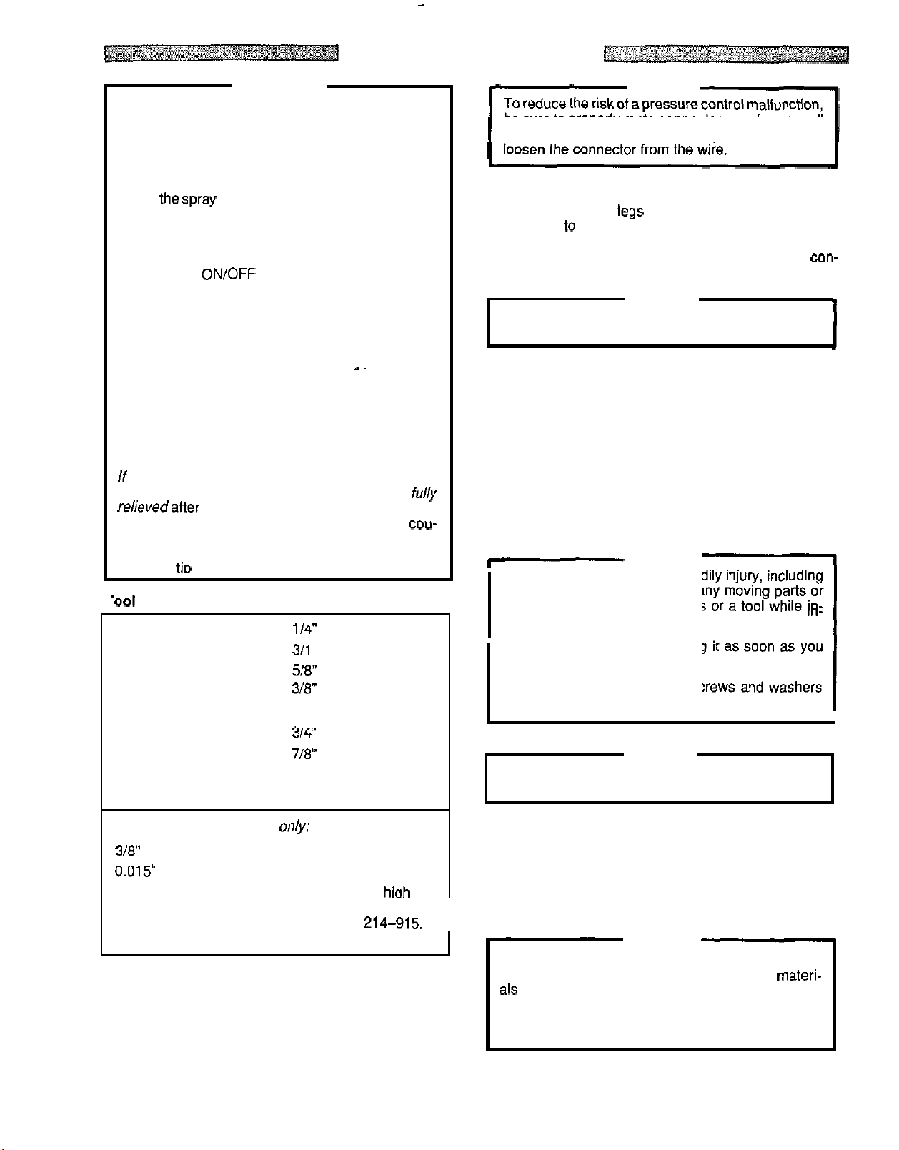
'001
List
Phillips screwdriver
Small flat blade
screwdriver
Needle nose pliers
Plastic mallet' 1/2 open end wrench
Adjustable wrench
2 adjustable,
open
Torque wrench
ON/OFF switch to OFF.
to
catch the drainage.
suspect that the spray
ti0
or hose obstruction.
114"
311 6 hex key wrench
518"
318" open end wrench
3/4" open end wrench
718"
-
end wrench
High quality motor oil
Bearing grease
.~
tip
or hose
has
hex key wrench
socket wrench
open end wrench
is
not been
com
fu//y
CAUTION
be sure
on a wire to disconnect
2. Route wires in the pressure control assembly care
-
Improper wire routing can result in poor sprayer per
formance or damage to the pressure control.
-
3. Keep all screws, nuts, washers, gaskets, and electri
-
4. Test your repair before regular operation of the
-
1-
To reduce the risk of serious bodily injury, including
electric shock,
electrical parts with your fingers or a tool while
specting the repair.
Shut
complete the inspection.
Reinstall all covers, gaskets, screws and washers
before operating the sprayer.
Do
to avoid damaging the pump packings.
to
properly mate connectors, and never pull
it.
Pulling on a wire could
fully through the legs
This is
which moves as the pressure setting changes, and to
avoid pinching the wires between the pressure
trol box and cover.
cal fittings removed during repair procedures. These
parts are not normally provided with replacement as
semblies.
sprayer to be sure the problem is corrected.
If the sprayer does not operate properly, review the
repair procedure again to verify that everything was
done correctly.
Troubleshooting Guide, pages 13
tify other possible problems and solutions.
to avoid interfering with the bourdon tube,
DO
off
the sprayer and unplug it as soon as you
of
the U-shaped bourdon tube.
con-
CAUTION
If
necessary, refer to the
-
20, to help iden
WARNING
NOT touch any moving parts or
in-
-
1
CAUTION
not run the sprayer dry for more than
30
seconds
-
-
-
-
For
calibration procedure
3/8" ignition wrench Clean water
0.015"
High pressure. oil
5 gallon pail
.
spray tip Mineral spirits
-
filled NEW
lest gauge,
Part No. 102
When disconnecting wires in the pressure control as
sembly, use needle nose pliers to separate mating
connectors.
When reconnecting the wires, be
of the insulated male connector
wraparound blade of the female
-
814
on&:
207
bar hioh
pressure spray hose,
Part No.
214-915.
sure the flat blade
is centered in the
connector.
I
-
5.
Reinstall the motor cover before regular operation of
the sprayer and replace it
directs cooling air around the motor to help prevent
overheating. It can also help reduce the risk of burns,
fire or explosion: see the
WARNING
During operation, the motor becomes very hot and
could burn your skin
als spilled on the hot, bare motor could cause a fire
or explosion. Always have the motor cover in place
during regular operation to reduce the risk of burns,
fire or explosion.
if
it is damaged. The cover
WARNING,
if
touched. Flammable materi-
below.
307470
21
Page 22

POWER SUPPLY CORD REPLACEMENT
WARNING
Before doing this procedure, follow the
Relief Procedure Warning
the risk of a fluid injection injury, splashing in the
eyes or on the skin, injury from moving parts, or
electric shock.
Refer
to
Fig
22-f
and
22-2
1.
Use the 19 mm open end wrench to remove the nut
(337)
from the filter stud (31
2.
Use the 13 mm socket wrench
(44)
Screws
frame.
3.
Remove the pressure control mounting bracket
using a Phillips screwdriver.
4.
Disconnect the power supply cord wires
control box terminal strip (336) using a screwdriver.
5.
Install the new power supply cord
verse order of disassembly.
6.
Have a licensed electrician install a new plug on the
other end of the cord. Be sure
regarding the type of plug
holding the pressure control
on page 21 to reduce
0).
to
to
follow all local codes
to
use.
Pressure
remove the three
from
(31
1) in the re-
to
the
(89)
the
Fig
22-1
FILTER REPLACEMENT
Relief Procedure Warning
the risk of a fluid injection injury, splashing in the
eyes or on the skin, injury from moving parts, or
electric shock.
Refer
to
Fig
22-2
1. Remove the pressure control cover and screws.
2.
Use a needle nose pliers to remove the four wires
from
the
filter (310).
3.
Use the
lockwashers (337, 338) on the outside of the
pressure control box.
4.
Remove the old filter and install a new one in the
reverse order of disassembly.
M8
wrench
on
page 21
to
remove the lower nut and
to
reduce
Fig
22-2
w-\
i
311
22
307-670
Page 23

ON/OFF SWITCH REPLACEMENT
WARNING
eyes or on the skin, injury from moving parts, or
electric shock.
Refer
to
fig
23-1
and
23-2
1. Remove the pressure control cover and screws.
2. Remove the wires attached to the switch (302) at
TPI and TP2. using a screwdriver. See page 26, Fig
26-2.
3. Use a 16 mm socket wrench to loosen and remove
the nut and rubber boot (303) from the top
pressure control box. Remove the switch guard
(304).
4. Remove the
5. Remove the wires attached to the switch TP4 and
TP3 using a screwdriver. See page 26, Fig
ONlOFF switch.
of
26-2.
the
Fig
23-,
303
6.
Attach the wires to
7. Install the new switch
rotation ring
the threads of the switch, and the external tab en
gages with the blind hole (D) of the pressure control
box. See Fig
8.
Install the switch guard (304), aligning the internal
tab with the groove in the threads.
9. Powder the inside of the rubber boot (303) with tal
cum, then shake excess out of boot.
10.
Install the nut and rubber boot and tighten.
11. Reconnect the wires to
12. Reinstall the pressure control cover and screws.
TP4
and TP3 of the new switch.
so
the internal tab of the anti-
(W)
engages with the vertical groove in
23-1.
TPI and TP2.
-
-
Fig
23-2
MICROSWITCH REPLACEMENT
3. Use the socket wrench to remove the nuts from the
Before doing this procedure, follow the Pressure
Relief Procedure
the risk of a fluid injection injury, splashing in the
eyes or on the skin, injury from moving parts, or
electric shock.
IWARI/*jl
Refer
to
fig
23-2
1.
Remove the pressure control cover and screws.
2. Disconnect both wires from the microswitch (306). 6. Reinstall the cover and screws.
Warning
on page
21
to reduce
~ ~~ ~~~
microswitch.
if
4. Check to see
has, be sure the fluid pressure is 0 bar, then loosen
the
two
6
just the distance from the top of the flag to top inside
of the pressure control box to 40.79
Tighten the screws and recheck the dimension.
5. Perform the
page 28 before regular operation
the flag
mm hex nuts behind the microswitch. Ad-
STALL
(X)
has been loosened.
PRESSURE
+/
-
0.254 mm.
CALIBRATION
of
the sprayer.
If
on
it
307-670
23
Page 24

BRIDGE RECTIFIER REPLACEMENT
Before doing this procedure, follow the
Relief Procedure Warning
the risk of a fluid injection injury, splashing in the
eyes or on the skin, injury from moving parts, or
electric shock.
iWARNINGl
Refer
to
Fig
24-f .
1.
Remove the pressure control cover and screws.
2.
Disconnect all wires from the bridge (308) at the ap
propriate terminals.
3. Outside the pressure control box on the right side are
two
screws (331). Loosen, but don't remove the
screw near the back mounting plate
loosen and remove the front screw. Slide the bridge
out.
4.
Slide the new bridge (308) into the box being sure the
lockwasher (333) on the rear screw (331)
FRONT of the bridge.
on page
Pressure
21
to
(89):
reduce
Then
is
IN
5.
Install.the front screw (331), lockwasher (333) and
nut (332).
CAUTION
The lockwashers (333) must be in front of the bridge
to
avoid overheating which will result in bridge
failure. Refer
6.
Make sure the bridge
and tighten the screws securely.
7.
Connect all wires. Carefully route the wires.
-
Be sure the flat blade of the insulated male
connector is centered in the wraparound blade of
the female connector when the connections are
made. Improper connections may cause the sprayer
to
malfunction. Route all wires carefully
interference with the movement of the bourdon tube,
circuit board, or control box cover which could cause
a malfunction.
8.
Reinstall the pressure control cover and screws.
to
the Detail in Fig
is
flush with the side of the box
CAUTION
24-1.
to
avoid
1
Fig
24
24-1
307-670
Page 25

CHOKE REPLACEMENT
WARNING
Before doing this procedure, follow the
Relief
Procedure
Warning on page
the risk of a fluid injection injury, splashing in the
eyes or
on
the skin, injury from moving parts, or
electric shock.
Refer
to
Fig
25
7.
1. Remove the pressure control cover and screws.
2.
Remove the grounding screw (312) and remove the
lead. Loosen the appropriate screw on the terminal
strip (336) and disconnect the
yellow/green choke
lead.
3.
Use
the M8 wrench
to
remove the upper nut and
lockwasher (337,338) on the outside of the pressure
control box.
4.
Remove the old choke (309) and install a new one in
the reverse order
of
disassembly.
Pressure
21
to reduce
-
309
VARISTOR REPLACEMENT
WARNING
Refer
to
Fig
25-2
and
25-3.
1. Remove the control box screws and cover.
2.
Remove the
(318, 319) and the old varistor from the
switch (302).
3. Trim the leads
Turn each lead outward
enough for
two
screws (AB), the wiring harnesses
on
the new varistor (339)
to
the
screws
(A,
form a
B)
to
pass through.
to
loop
that is large
ON/OFF
28.5 mm.
Fig
25-1
318
319
A
FRONT VIEW SIDE VIEW
Fig
25-2
4.
Place a wiring harness on each screw, then place a
loop of the varistor leads on each screw and thread
the screws
into
the switch.
5. Wrap the varistor under the switch.
Fig
25-3
\
FORM
LOOP
ENOUGH FOR SCREWS
TO
PASS
THROUGH
307670 25
LARGE
Page 26

~~
CIRCUIT
eyes or on the skin, injury
electric shock.
I
Refer
to
Fig
212-1
and
26-2.
1.
Remove the pressure control cover and screws,
2. Turn the pressure control knob all the way
clockwise
tension
three or four threads of the pressure control knob
shaftareexposed below the pressure adjustment nut
(S).
Step 2
circuit board while removing or installing it.
3. Disconnect ALL wires from the board, including the
two
connections are made. See Fig
4.
To remove the board from the box, pull out the black
plastic
cuit board toward the wall of the box and carefully
slide the board out.
5.
Install the board in the box at the same angle as
was removed.
to
the minimum setting
on
the board. Also check to be sure only
Back down the nut,
CAUTION
is
essential
heavy black wires. Pay close attention to where
-
tipped pin (330). Push the bottom of the cir
to
reduce the risk of damaging the
from
moving parts, or
to
if
necessary. See Fig 26-1.
26-2.
BOARD
counter-
release spring
*~
it
REPLACEMENT
CIRCUIT
I
Fig
261
Be. sure the flat blade of the insulated male
connector is centered in the wrap
the female connector when the connections are
made.
Route all wires carefully to avoid interference with
-
the circuit board, bourdon tube, or pressure control
cover.
These precautions are essential to reduce the risk of
a malfunction.
r
PRESSURE
CAUTION
CONTROL
-
around blade
KNOB
of
i
REF
321. REF 320
7.
Perform the
starling on page 28,
STALL
PRESSURE
if
you installed a new board.
CALIBRATION
TPIO
Fig
26
262
307470
.
LY"
Page 27

PRESSURE CONTROL REPLACEMENT
WARNING
Before doing this procedure, follow the
Relief
Procedure Warning
on page 21
the risk of a fluid injection injury, splashing in the
eyes or on the skin, injury from moving
electric shock.
Refer
to
Fig
28
-
1.
Pressure
to
reduce
parts, or
9. Perform the
starling on page
STALL PRESSURE CALIBRATION
28,
before regular operation of the
sprayer.
CAUTION
Do not allow the adapter
the new pressure control assembly. Turning
(A)
to
turn while installing
it
damage the sensitive bourdon tube. Hold .the
adapter firmly with a 19
mm open end wrench while
screwing In the nipple (123).
can
1. Disconnect the main fluid hose (23) and the secon
dary fluid hose,
2. Disconnect the fluid hose
placement pumpoutlet nipple
trol inlet elbow
3.
Hold the hex of the pressure contwl adapter
if
used, from the sprayer.
(47)
from between the dis
(46)
andpressurecon-
(78).
(A)
firmly with a 19 mm open end wrench. Use a wrench
to
unscrew the nipple (123) and filter.
4.
Remove the pressure control cover and screws, and
disconnect the four motor leads at the appropriate
terminals.
5.
Refer to
CIRCUIT BOARD REPLACEMENT
on
page 26, remove the circuit board and retain.
6.
Remove the conduit (22).
7.
Use a 13 mm open end wrench to loosen and remove
the three pressure control mounting screws
(40)
lockwashers
and nuts (120) located below the
pressure control box. Remove the box.
8.
Install the new pressure control assembly in the re
(44)
-
and
verse order of disassembly.
-
-
-
Fig
28-1
307
-
670 27
Page 28

STALL
PRESSURE
CALIBRATION
WARNING
USE EXTREME CAUTION WHEN
fluid injection injury or other serious bodily injury which can result from component rupture, electric shock,
explosion, or moving parts.
This procedure sets the sprayer
WORKING PRESSURE. Perform this procedure PRESSURE. Normal operation
whenever the pressure control assembly
and reinstalled or replaced
properly calibrated.
Improper calibration can cause the sprayer
pressurize and result in component rupture, fire or ex- rated hose
plosion.
the maximum working pressure, resulting in poor
sprayer performance.
NEVER attempt
by performing these calibrations in any other way. duce the risk of electric shock.
Service Tools Needed:
NEW 15.2 m,
hose, Part No.
0-5000 psi (0-350 bar) fluid-filled pressure gauge,
Part No.
It
may alsopreventthesprayerfrom obtaining
to
increase the fluid outlet pressure sembly when the control box cover is removed,
231
bar, flexible, nylon airless spray
210-541
102-814
to
PERFORMING
to
207 bar MAXIMUM NEVER EXCEED
is
removed higher pressures could result in component rupture,
be sure the sprayer is fire or explosion.
to
THIS CALIBRATION PROCEDURE to
new1 5.2 m spray hose rated for at least 207 bar
over
Use a
-
could
tUre,
AVOID touching the wire in the pressure control as-
207
bar MAXIMUM WORKING
PRESSURE.
develop a high
reduce the risk of a
of
the sprayer at
A
used,
pressure
leak
fire,
under-
or
rup-
to re-
New spray tip, size 0.015”
5 gallon pail and water
Mineral spirits
Calibration Setup.
Refer
fig
28-f
and
29-1.
1.
Follow
page
0.01
test hose and connect the hose
2. Remove the pressure control screws and cover.
3.
Remove the plug from the top of the fluid filter, and
install the test gauge (W).
4.
Place the pump suction tube in a5gallon pail ofclean
water.
5. Be sure the gun safety latch is engaged
the
Pressure
21.
Remove the spray hose and gun. Install a
5”
spray tip in the gun. Connect the gun
Procedure continued on next page
Relief
Procedure Warning
to
the sprayer outlet.
to
a new
on
Fig
20-1
28
307670
Page 29

6.
Use a 9 rnm ignition wrench
justment nut
(S)
counterclockwise about
STALL
to
turn the pressure ad
PRESSURE
turns. See Fig 29-1.
7.
With the pressure control knob
setting, turn the sprayer switch
THE DISPLACEMENT PUMP SHOULD
If
it does cyde, shut the sprayer switch OFF, disen-
(B)
at the minimum
ON.
See Fig 29-1. mineral spirits in the pump
NOT
gage the gun satety latch, trigger the gun into a
grounded waste container until pressure is relieved,
and engage the latch again. Turn the nut
(S)
further clockwise. Turn the sprayer on again to be
sure
THE
8.
Slowly
turn the pressure control knob
to the maximum
PUMP
DOES
NOT
CYCLE.
(B)
clockwise
setting and hold it there. Use a9 rnm
ignition wrench to slowly turn the pressure adjust
ment nut
ACTLY
(S)
clockwise until the test gauge reads
207 bar.
two
full
CYCLE
a little
EX-
CALIBRATION
-
To
prevent
the pump, hose and gun with mineral spirits.
to close the drain valve, first. ,Use the lowest
pressure necessary to flush. Follow the
Relief Procedure Warning
ready to spray again.
10
Remove the test gauge assembly and reinstall the
plug. Flush out water with mineral spirits.
-
pump
corrosion, flush the water out
on page
to
protect it until you are
~~
-
Pressure
21.
Leave the
Be
of
sure
9. The calibration procedure is now completed.
WARNING
Follow the
page
Pressure Relief Procedure Warning
21.
on
Fig 29-
1
307470
29
Page 30

BEARING HOUSING & CONNECTING
ROD
REPLACEMENT
Before doing this procedure, WARNING follow
Relief
the risk of a fluid injection injury, splashing in the
eyes or in the skin, injury from moving parts or
tric shock. Be sure to unplug the sprayer!
Refer
NOTE: Stop the sprayer at the bottom of its stroke
1.
2.
3.
4.
5.
Procedure
to
Fig
30-1
the crank
must be lowered manually, carefully rotate the
blades of the fan with a screwdriver.
Remove the front cover and screws (31, 32).
If
the crank
rotate the blades of the fan with a screwdriver.
Unscrew the suction tube (42) from the
ing a wrench
pump from loosening.
Disconnect the pump outlet hose (47) from the
placement pump outlet nipple (46).
Use a screwdriver to push aside the retaining spring
(35) at the top of the pump. Push the pin (20) out the
rear.
Warning
for Steps
(E)
in its lowest Dosition. If the crank
(E)
must be lowered manually, carefully
on
the pump intake valve
-1
the
on
page 21 to reduce
7
to
74.
Pressure
elec- premature bearing wear.
~ ~ ~ ~~ ~~
pum6,'hold-
to
keep the
to
get
dis-
DO
NOT
use
the bearing cAuTIoN-1 housing screws (33) to
to
align or seat the bearing housing; the bearing and
drive housing will not align properly and will result in
14. Install the screws (33) and lockwashers
bearing housing and tighten evenly
FILL
procedure continued
CAVITY
WITH
on
page
(49)
to
13-16 N.m.
3
7
try
on the
6.
Loosen the jam nut (38) with an adjustable wrench.
Unscrew and remove the displacement pump.
7.
Use a
screws (33) and lockwashers (49) from the bearing
housing (27).
8.
Lightly tap the lower rear of the bearing housing (27)
with a plastic mallet to loosen it from the drive
ing (2). Then pull the bearing housing and the con
necting rod assembly (3) straight
ing.
9.
Inspect the crank
parts as needed.
10
Evenly lubricate the inside of the bronze bearing in
the bearing housing with high quality motor oil. Liber
ally pack the roller bearing in the connecting rod as
sembly (3) with bearing grease.
11. Assemble the connecting rod and bearing housing
(27).
12. Clean the mating surfaces of
housings.
13. Align the connecting rod with the crank (E) and care-
fully align the locating pins in the drive housing with
the holes in the bearing housing (27). Push the bear-
ing housing
with
5
mm hex key wrench to remove the four
off
the drive hous
(E)
for excessive wear and replace
the
bearing and drive
onto
the drive housing or tap
a
plastic mallet.
hous-
it
into place
-
-
-
-
42
W
Fig
3CL1
30
307470
Page 31

-
BEARING HOUSING & CONNECTING
Refer
to
Fig
3
1 - 1
14. Screw the displacement pump about 314 of the way
into the bearing housing
the pin hole in the connecting rod assembly (3) and
continue screwing in the pump until the pin slides
easily into the hole. Back off the pump until the top
threads of the pumpcylinder are flush with the face of
the bearing housing and the outlet nipple
ing back. Push the retaining spring (35) into the
groove -all the way around the connecting rod.
Tighten the locknut (38) very tight
N.m- with a 2-1/4 in. open end wrench and a light
hammer.
Be sure the retaining spring (35) is- firmly in the
groove all the way around,
from working loose due
If the pin works loose, it or otherparts could break
due
to
could be projected through the air and result
ous
bodily injury or property damage, including dam
age
to
SeeFig30-1and31-1.
the force of the pump action. These parts
the pump connecting rod or bearing housing.
(27).
WARNING
to
prevent the pin
to
vibration. See
Hold the pin (20) up
(46)
is fac-
-
about
Fig
90
to
(20)
31-1.
100
off
in
seri
to
-
-
ROD
REPLACEMENT
90-100
N.M
15.
Reinstall the front cover and screws (31,32). Recon
nect the suction tube (42) and pump outlet hose (47).
Fig
30
-
See
1.
-
Fig
31-1
307670
31
1
!
i
Page 32

DRIVE HOUSING REPLACEMENT
the risk of a fluid injection injury, splashing in the
eyes or in the skin, injury from moving parts or elec
tric
shock. Be sure
Refer
to
Fig
32-17.
NOTE:
1.
2.
3.
4.
Stop the sprayer at the bottom of its stroke to get
the crank
manually, carefully rotate the blades of the fan
with a screwdriver.
Remove the front cover and screws (31, 32). Re
move the six screws (1 19) and motor cover (14).
Disconnect the pump outlet hose (47) from the dis
placement pump outlet nipple (46).
Use a 5 mm hex key wrench to remove the four
screws
housing.
Lightly tap the lower rear of the bearing housing (27)
with a plastic mallet to loosen
ing
rod assembly straight
(33)
(2).
Then pull the bearing housing and connecting
to
unplug the sprayer!
(E)
in its lowest position. To lower it
and lockwashers (49) from the bearing
it
from the drive hous
off
the drive housing.
-
CAUTION
DO
NOT
allow the gear cluster (9)
moving the drive housing (2). It is easily damaged
-
-
-
-
dropped. The gear may stay engaged in either the
front end bell or the drive housing.
DO
NOT
lose the thrust balls (10) located at each
end of the gear cluster (9) or allow them to fall be
tween gears. The balls, which are heavily covered
with grease, usually stay in the shaft recesses, but
could be dislodged. If caught between gears and
not removed, the balls will seriously damage the
drive housing.
ings will wear prematurely.
7. Liberally apply bearing grease to the gear cluster (9).
Check
8.
Place the bronze-colored washer
ver-colored washer (4) on the shaft protruding from
the big gear in the drive housing (2). Align the gears
and push the new drive housing straight onto the
front end bell and locating pins.
9. Starting at Step
to
reassemble the sprayer.
If
the balls are not in place, the bear
to
be sure the thrust balls
5
and working backwards, continue
..
to
fall when re
(1
0)
are in place.
(5)
THEN
-
if
-
-
the sil-
5.
Use a 6 mm hex key wrench to remove the two
(65)
screws (51) and lockwashers
the drive housing, the
ckwashers (65) from the rear
bell (Ib) and the two screws (21) and lockwashers
(65)
from the upper rear
(Ib).
6.
Lightly tap the drive housing
to
loosen
off.
it
from the front end bell, then pull
.
two
of
from the recess of
screws
of
the motor front end bell
(2)
(30)
the motor front end
with a plastic mallet
it
and
lo-
straight
Fig 32-1
32
307-670
i
Page 33

MOTOR
WARNING
REPLACEMENT
NOTE:
New motor brushes are included with each
Packing Repair Kit. Replace them when
replac-
ing the packings, and/or when they have been
worntoaminimumof14mmonthelongestside.
1.
Remove the motor cover screws
(14).
See
Fig
33-1.
2. Remove the screws
(H),
inspection covers
gaskets (K) on each side of the motor. See
(1
19)
and cover
(J)
and
Fig33-I.
3. Loosen the brush lead terminal scrsw and remove
the lead.
4.
Push down on the spring clip slightly then pull the clip
away from and out
33-2.
Keep the spring clip.
5.
Remove and discard the brush.
6.
Inspect the commutator for excessive pitting, burn
ofthe brush holder.
Refer
to
Fig
ing or gouging.
NOTE:
A
black color on the commutator is normal.
Have the commutator resurfaced by a qualified
motor repair shop
too
wearing
fast.
if
the brushes seem
to
be
Fig 33-
1
SPRING
107-398
CLIP
\
,
BRUSH
'
BRUSH
HOLDER
107-149
-
COMMUTATOR
7.
Placea new brush in the holder
are as shown in the first part of Fig 33
so
the bevelededges
-
2, and the
brush lead is routed as shown in the second part of
Fig
33-2.
8.
Slowly push the tabbed end of the spring clip into the
brush holder until the clip tab engages. in the holder
and the rolled .portion of the tension spring rests
squarely on the brush.
9.
Route the brush lead
to
the terminal and tighten the
terminal screws. Be sure the brush lead does not
touch any part of the armature or motor housing.
10.
Test the brushes:
a.
With the ON/OFF switch OFF, turn the pressure
control knob all the way counterclockwise
minimum pressure. Plug in the sprayer.
b. Turn the
ON/OFF switch ON and slowly increase
the pressure until the motor comes up to full
speed.
c. Inspect the brush and
for excessive arcing. Arcs should not
commutator contact area
"
trail" orcir-
cle around the commutator surface.
WARNING
Do not touch the brushes, leads, springs or brush
holders while the sprayer is plugged in to avoid
electric shock and possible serious bodily injury.
to
CAPACITOR
BRUSH HOLDER
\
MOTOR
/
END
BELL
Fig 33-2
Do
not
run the sprayer dry for more than
ICAUTIONl
while checking the brushes
disDlacement DumD.
11.
Reinstall the brush inspection covers, gaskets, and
to
avoid damaging the
30
seconds
screws. Reinstall the motor cover and screws.
307-670
33
Page 34

MOTOR CAPACITOR REPLACEMENT
WARNING
1,
Remove the control box cover. Disconnect the motor
leads.
2.
Remove the fan cover
of
rear
3.
Use a screwdriver to gently lift the fan tab out of the
motor shaft groove and remove the fan
4.
Remove the inspection cover
gasket
34
5.
Push down slightly on the spring clip and pull tiieclip
out of the brush holder. See
6.
Gently push the brushes
inspect. Replace
7.
Make a matchmark between the front end bell and
the motor housing and the rear end bell (M) and the
motor housing
reassembly. Also make a mark on the front of the mo
tor housing. Refer
8.
Use a
the rear end beii (M).
the motor. See
(K)
from each side of the motor
-
1.
11
mm socket wrench
(1)
(F)
and screws
Fig
34-1.
(J),
Fig
out
of the brush holder and
if
necessary. See page
to use as alignment marks during
to
Fig
34-1.
to
remove the nuts from
(G)
(N).
screws
(1).
34-2.
33.
from the
(H),
and
See
Fig
-
Fig
34-1
9.
Gently tap alternate ears of the rear end bell with a
plastic mallet to loosen it, then pull it straight
not pull the motor armature out. Retain any washers
that fall out when the bell is removed.
10.
To
replace the capacitor, remove the brush lead ter
minal screws
sulation plate of the rear end bell (P). Install a new
capacitor.(X). making sure the ceramic case of the
capacitor is not cracked. Maintain a
between the capacitor and any grounded metal
patis. Always replace both capacitors at the same
time.
11.
Position the rear end bell (M) over the tie bolts and
push
matchmarks carefully and install the lockwashers
and nuts.
12.
Position the fan
into place, making sure the fan tabs engage in the
motor shaft groove.
13.
InStall the fan cover
14.
Reconnect the motor leads in the pressure control
box and reinstall the conduit
seal
(8)
See
Fig
and
screws.
(Y)
and the screw
it
onto the motor housing. Align the
(N)
over the motor shaft and push it
(F)
and screws
into conduit elbow, around the motor lead.
35-1.
Reinstall the pressure control cover
(2)
going into the in
3
mm clearance
(G)
(77b) and push conduit
off.
Do
-
-
INSULATION
BRUSH LEAD
BRUSH HOLDER
Fig
34-2
'
ut
It
DETAIL
WITH MOTOR LEAD FACING BACK
OF
MOTOR BRUSH SHOWN
MOTOR
"
OF
i
34
307470
Page 35
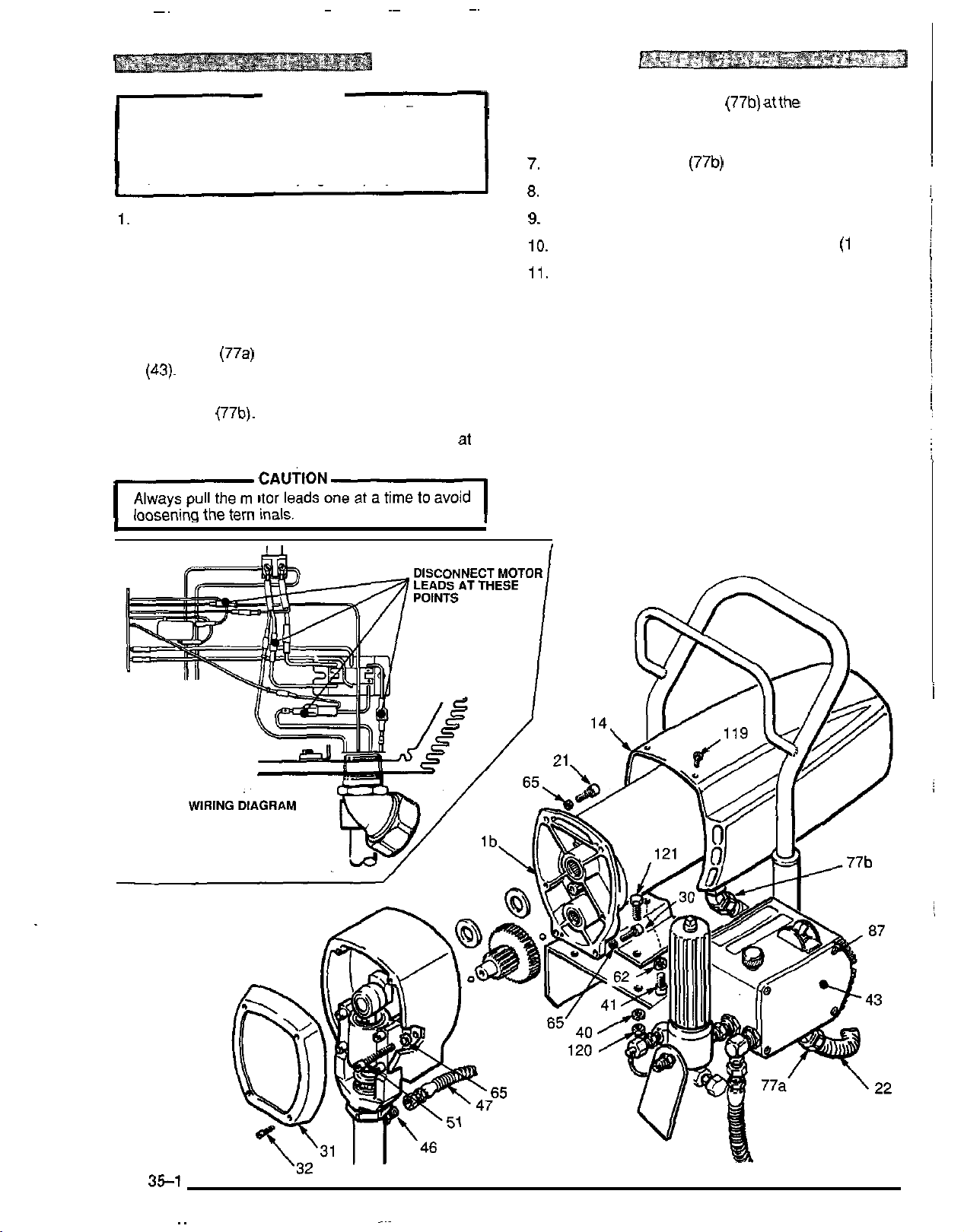
~~
~
~~
~~
MOTOR
REPLACEMENT
WARNING
Before doing this procedure, follow the Pressure
Relief Procedure Warning on page 21
to
reduce
the risk of a fluid injection injury, splashing in the
eyes or in the skin, injury from moving parts or elec
-
tric shock. Be sure to unplug the sprayer!
1. Disconnect the pump outlet hose (47) from the dis-
placement pump outlet nipple (46).
2.
Remove the pressure control cover and screws and
disconnect the four motor leads. Remove the con-
duit seal from the conduit elbow coming into the con
trol
box.
3.
Use an adjustable wrench to loosen the conduit con
nector nut
(77a)
at the pressure control assembly
(43).
4.
Swing the conduit (22) away from the-pressure con
trol elbow (77b).
5.
Pull
the motor leads through the elbow, one at a
'
time.
Always pull the motor leads one at a time to avoid
loosening the terminals.
I
I
.
cAuT'oNl
6.
Loosen the connector nut (77b) atthe motor and pull
the conduit (22) away from the motor, then pull the
leads through the conduit, one at a time.
7.
Unscrew the elbow (77b) from the motor.
8.
Pull
the wires through the elbow, one at a time.
9.
Remove the front cover and screws (31, 32).
10. Remove the motor cover (14) and screws
(1
19).
11, Use a 6 mm hex key wrench to remove:
-
two
screws (51) and washers (65) from the recess of
the drive housing,
-
two
screws (30) and washers (65) from the lower
rear of the motor front end bell (Ib),
two
-
I
screws (21) and washers (65) from the upper
rear of the motor front end bell (1 b).
I
Fig
35-1
307-670 35
~~
Page 36

MOTOR
REPLACEMENT
12. Use a plastic mallet
pump (39) from the rear
from the front end bell. Then pull the drive housing
away from the end bell.
DO
NOT allow the gear cluster (9)
moving the drive housing
dropped. The cluster may stay engaged in either
the front end bell or the drive housing.
DO
NOT lose the thrust balls
end of the gear cluster (9) or allow them
tween
gears. The balls, which are heavily covered
with grease, usually stay in the gear recesses, but
could be dislodged: If caught between gears and
not removed, the balls will seriously damage the
drive housing.
ings will wear prematurely.
13. Use a 6 mm hex key wrench to remove the four
screws (1
the motor bracket (A). Be sure to support the motor to
keep the sprayer from tipping.
If
21), lockwashers
to
gently tap the displacement
to
loosen the drive housing
CAUTION
to
fall when re
(2).
It is easily damaged
(1
0)
located at each
to
fall be
the balls are not in place, the bear
*.
(40)
and nuts (120) from
-
if
-
-
14. Lift the motor assembly
screws'(41) and lockwashers
motor bracket (A).
15.
Secure the motor bracket
the motor assembly with the frame mounting holes.
Install the screws
(120).
16. Liberally grease the gear cluster (9) and pinion gear
(B)
and pack all bearings in the motor front end bell.
Check
17. Place the bronze
silver
from the big gear in the drive housing (2).
18. Align the gears and push the drive housing (2)
straight onto the front end bell and locating pins.
19.
Starting at Step
to reassemble the sprayer.
NOTE:
20. Reinstall the motor cover and pressure control cover.
to
be sure the thrust balls
-
colored washer
-
colored washer
12
Use a turning motion on the conduit (22) when
feeding wires through it.
off
the frame. Remove the
(62)
and remove the
(A)
to
the new motor. Align
(121), lockwashers
(4)
on the shafi protruding
and working backwards, continue
(40)
(1
0)
are in place.
(5)
and THEN the
and nuts
i
36 307-670
Page 37

NOTES
307670 37
Page 38

~~~
PARTS - COMPLETE SPRAYER
38
307-670
Page 39

PARTS
DRAWING
-
BASIC
SPRAYER
REF
NO.
PART
1
221-069
Ib 220
le
107-219
1
f
178-934"
~~
-
995
"
NO.
lg 107-267
Ih 107-264
2
218-032
2a
107-327
3 218-034
4 178-967
5
107-089
6 220-365
8
107-447
9 179-961
10M69
10
14 181-743
14a
179-948
14b 179-951
14c
178-934'*
15 214-701
-
16 220
20 176
21
955
-
818
101-682
22 065-099
23 210-541
218435
27
30 100-643
TOMOTOR
DESCRIPTION QTY
MOTOR, electric 1
Includes replaceable items Ib,
and one of item
10
.HOUSING, motor
.BUSHING, 3/4 npt(rn)
.
.LABEL, WARNING
le-lh,
(Irontendbell)
x1/2
.TERMINAL
.TERMINAL
DRIVE HOUSING ASSEMBLY
Includes replaceable Item 2a
.GREASE, gear,
10
02.
ROD, connecting
SPACER
WASHE
R, race
CART
Includes replaceable items
54,
57
:
58
SEAL, conduit
GEAR CLUSTER
BALL, STEEL;
114 dia.
MOTOR COVER ASSY.
Includes items 14a - 14c
.LABEL, identification
.LABEL, identification
.LABEL, WARNING
HOSE, grounded, nylon;
ft
(0.9
m)
3/16 ID; 3
long;
spring guards both ends
GUN. airless
SEE
307-614
FOR
PARTS
PIN, strai ht. hdls
CAPSCREW, socket head;
x
5/8"
1/4
long
CONDUIT, electrical 241
HOSE, grounded, nylon;
50
ft
(1 5 rn) long;
1/4"
sprin guard both ends
HOUhNG, bearing
CAPSCREW,
SOC
hd; 114
,
.
rrn
x
1"
npt(f) 1
1
2
2
1
1
1
1
1
1
2
1
1
1
1
1
1
1
1
1
2
MM
ID
;
1
1
2
REF
NO.
PART
31 218-328
179-950" .LABEL.
31a
32 107-209 SCREW. mach. filh:
I
NO.
DESCRIPTION
COVER, bearing housing;
"_.
8-32x
WARNING
. . .
.. ..
1"
~~ ~
no.
33 107-210 CAPSCREW, sch; 3/8-16
unc-3a x 1-1
35
176-817
36 21
36a 179
8-326
-
949 .LABEL, identification
SPRING, retaining
COVER, pressure control
INCLUDES'ITEMS
36b 177-762** .LABEL, WARNING
38
178-941
39
218-347
40 100-214
41 107
-
212
42 180-573
43 221
44 101
-
-
116
344
46 162-453
NUT, hex
DISPLACEMENT PUMP
SEE
307-793
LOCKWASHER, 5/16
CAPSCREW,
x
0.5
SUCTION TUBE
PRESSURE CONTROL ASSY
SEE SEPARATE PARTS
ON
PAGE
40
CAPSCREW, hex head:
-
18 x 7/8" long
5/16
NIPPLE, hex; 1/4 npsm
1/4 nDt. 1-3/16 lona
47
218-083
HOSE,'grounded, nylon;
114
ID; 29 (736 rn) long;
spring guard both ends
48 214-570
49 106-115
50
220-286
51 107-218
54 107-310
176-884
57
58 101
59
-
242
104-811
60 106062
62
104-008
65 105-510
~~~
66 178-034
77 108-460
78 100-840
FLUID FILTER
See 307-273 lorparts
LOCKWASHER, spring; 3/8
PRESSURE DRAIN VALVE
CAPSCREW, sch; 1/4
x
2.75"
CiP3 iubing
WASHER
RING, retaining
HUBCAP
WHEEL
LOCKWASHER, spring, 5/16
LOCKWASHER, spring;
TAG. WARNING
~~~
CONNECTOR, conduit
ELBOW, street, 1/4
114 npt(f)
84
206-994
87
106075
89
183-573
115
181-072
118 218-355
1
19 108-865
THROAT SEAL LIQUID
8
02.
(0.27 liter)
SCREW, mach,
-
24 x 112, type "C
no 6
MOUNTING BRACKET
STRAINER
CIRCUIT BOARD
SEE PAGE
40
SCREW, rnach; panhead;
no. 8-32 x 3/8 long
120 100
121 100
122
123
124
-
1 88
-
057
183-664
165-198
220-285
NUT, hex, 5/16
CAPSCREW, hex
-
18 X 3/4
5/16
PLATE, mounting
NIPPLE, rdcg; 3/8
CAP
...
.
-
..
/2
36a. 36b
FOR
PARTS
SOC
hd; 5/16
LIST
x
-
20
1/4
,
ovhd,
-
18
npt(m)
hd;
x
x
thd frmg;
"
1/4 npt
QTY
1
1
4
4
1
1
1
1
1
1
7
2
1
1
3
3
1
1
4
1
2
2
2
2
2
2
2
6
1
2
2
1
8
1
1
1
6
7
4
1
1
1
"Eztm warning labels available free.
307-670 39
Page 40

PARTS
-
PRESSURE
PRESSURE CONTROL ASSEMBLY 221-116
REF
NO. PART NO. DESCRIPTION QTY
CONTROL
REF
NO. PART NO. DESCRIPTION QTY
I
I
!
,
i
300 218-351
302 107-437
303 105-659
304 107-255
306 107-435
308 218-400
309 218-366
wn 1n71477
-
.
- . -
.
31 1 065-140
312 100-035
318 218-365
~ ~ ~ ~ ~
319 218-368
320 218-369
321 218-370
322 218-371
323 218-372
324 107-438
PRESSURE CONTROL
INCLUDES
.ON/OFF SWITCH
.BOOT. switch
.GUARD, locking
.MICROSWITCH
RECTIFIER, bridge
CHOKE
FIITFR
,
-
. .
CORD SET, power supply, no plug
SCREW, mach; slotted
pan hd;
HARNESS. wire
HARNESS, wire
HARNESS, wire
HARNESS, wire
HARNESS, wire
HARNESS, wire
SCREW, mach,
no. 5-40
. - . -.
.
no.
~...~
x
1
302
TO
306
1
1
1
1
1
1
I
1
8
x
5/16'
~
fil
head;
1
1
1
1
1
1
5/8" 2
325 100-975
326 101-972
327
157-021
328 108-295
329 107-258
330 180-041
331 101-273
332
100-1
333 100-718
334 178
-
335 178-035..
336 107-436
337 105-329
1
338 100
-
339 108-096
'Extra warning labels available free.
NUT, hex mach,
LOCKWASHER, ext;shakeproof; no.
LOCKWASHER. no. 8 internal
BUSHING. strain relief
TIP, pin, black plastic
PIN
SCREW,
79
NUT, hex, mscr, no.
LOCKWASHER, internal,
shakeproof, no.
797
"
LABEL. warnina
LABEL
TERMINAL, strip
NUT, hex, M8
109
LOCKWASHER, external
shakeproof;
VARISTOR
mach;
; warnins
x
5/16
n0.5
flat hd; no.
10-24
10
1.25
2
5 2
1
1
1
1
10-24 x 5/8" 2
thd
2
2
1
1
1
2
2
1
40
307670
'
337
338
!
Page 41

THESE WIRES ARE CONNECTED
TO
TWO
TERMINALS ON THE OTHER
SIDE
OF
THE ON/OFF SWITCH
WIRING
\
DIAGRAM
,302
307-670
41
Page 42

ACCESSORIES
DISPLACEMENT PUMP REPAIR KIT 220-845 SUCTION TUBE KIT208-259
Repair instructions included with kit. Includes:
MOTOR BRUSH KIT
220-367
Repair instructions included with kit.
SUCTION TUBE KIT
208-920
5
Includes:
REF
NO.
1
2
3
4
5
6
PART
NO.
101-818 CLAMP,HOSE
16&327 UNION, 90 DEG SWIVEL;
17&705 ADAPTER. INTAKE
17&706
17&957
181472
DESCRIPTION
NPT(M X F)
3/4
HOSE, 1” iD X 48”; NYLON
TUBE. SUCTION
STRAINER
gallon
(1
9
liter)
size
QN
REF
NO. PART NO. DESCRIPTION
1
156589 UNION, 90 DEG ADAPTER;
2
214-961
3 156591
4 156
5
6
1
7 156-592 TUBE, RISER
8
I
9 161-377
10 159-101
-
100-220
176-684
15(t100 RETAINER, SCREEEN
314 NPT(F) X 3/4 NPT(F) SW
HOSE,
314 ID; NYLON;
SPRING GUARD ONE END
ELBPW.
X
593
1-1/2 - 24 NS
PACKING, O
THUMBSCREW. 5/1+18 X 1”
ADAPTER, BUNG
SCREEN, FILTER
NUT, SCREEN RETAINER
CPLD
314 NPT(MBE);
90
DEG; 3/4 NPT
-
RING, NITRILE
55
gallon
(200
liter) size
c
QN
1
6
FT
(1.8
M);
!
1.
42
307670
Page 43

TECHNICAL DATA
Power Requirements
Working Pressure Range
Cycles/liter
Maximum Delivery
Power Cord
Inlet Paint Strainer
Outlet Paint Filter
................................
............
............
..................
..................
Stainless Steel Screen, reusable
....................
Stainless Steel Screen. reusable
DIMENSIONS
Weight
Height
Length
Width
(dry
w/o packaging)
...............................
...............................
................................
,230 VAC, 50Hz,
1
phase, 7 amp minimum
.............
No.
14 AWG, 3 wire, 2.6
........
0
3.2 literlmin
1190
250 micron
43 Kg (approx.)
-
207 bar
micron
71
1
mm
660mm
572mm
53
m
Pump Inlet Size
Fluid Outlet Size
Wetted Parts:
Displacement Pump
UHMW polyethylene,
Filter
....
Aluminum, Carbon steel, Stainless Steel,
NOTE:
DelrinB
.....
3/4 npt(m) with
..........
. .
Carbon steel, Polyurethane,
20"
ID chamfer
1/4 npsm from fluid filter
DelrinB, Leather
307-670
43
Page 44

WARRANTY
I
THE GRACO WARRANTY AND DISCLAIMERS
Graco warrants all equipment manufactured by
workmanship on the date of sale by an authorized Graco distributor to the
purchaser's sole remedy for breach of this warranty, Graco will, fora period of
it
and bearing its name to be free from defects in material and
orlginal purchaser for
use.
twelve months from the date of
As
sale, repair or replace any part of the equipment proven defective, with the exception of defects in parts on
the drive
or replaced for twenty
Gas Mechanical (GM)
and Electric
and maintained in accordance
train/gear box on EM and GM sprayers or power train on EH & GH spfayers, which will be repaired
-
four months from the date of sale for Gas-Hydraulic (GH) and
s
rayers and for thirty-six months from the date of sale for Electric-Mechanlcal (EM)
-
Hydraulic EH) Sprayers. This warranty applies on1 when the eqwpment is installed, operated
wlth Graco's wrltten recommenJations.
..
This warranty does not cover, and Graco shall not be liable for, any malfunction, damage or wear caused by
faulty installation, misapplication, abrasion, corrosion, inadequate or improper
malntenance, negllgence,
accident, tampering, or substitution of non-Graco component parts. Nor shall Graco be liable fo! malfunc-
tion, damage or wear caused by the incompatibility with Graco equipment of structures, accessorles, equip
-
ment or materials not supplied by Graco, or the improper design, manufacture, installation, operation or
or
maintenance of structures, accessories, equipment
This warranty is conditioned upon the repaid return of the equipment claimed to
ized Graco
dlstributor for verification o8he claim. If the claimed defect isverified, Graco will repair or replace
materials not supplied by Graco.
be
defective
to
an author-
free of charge any defective parts. The equipment will be returned to the original purchaser transportation
If
prepaid.
inspection of the equipment does not disclose any defect in material or workmanship. repairs will
be made at a reasonable charge, which charges may include the costs of parts, labor and transportation.
DISCLAIMERS AND LIMITATIONS
THE TERMS OFTHIS WARRANTY CONSTITUTE PURCHASERS SOLE AND EXCLUSIVE REMEDY AND ARE IN LIEU OF ANY
OR
OTHER WARRANTIES (EXPRESS
NESS FOR A PARTICULAR PURPOSE, AND OF ANY
BASED ON NEGLIGENCE
DAMAGES
AMOUNT
YEARS OF THE DATE OF SALE.
OF
OR
LOSS
THE
OR
STRICT LIABILITY. EVERY FORM OF LIABILITY FOR DIRECT, SPECIAL OR CONSEQUENTIAL
IS
EXPRESSLY EXCLUDED AND DENIED. IN NO CASE SHALL GRACOS LIABILITY EXCEED THE
PURCHASE
IMPLIED), INCLUDING WARRANTY
PRICE
.
ANY
ACTION
NONXONTRACTUAL LIABILITIES, INCLUDING PRODUCT LIABILITIES,
FOR
BREACH
OF
O
F
WARRAN+
MERCHANTABILITY
MUST
BE
BROUGHT
OR
WARRANTY OF FIT-
WITHIN
TWO
(2)
!
...
,
(.
i
EQUIPMENT NOT COVERED BY GRACO WARRANTY
GRACO MAKES NO WARRANTY, AND DISCLAIMS ALL IMPLIED WARRANTIES
PARTICULAR PURPOSE, WITH RESPECTTO ACCESSORIES, EQUIPMENT, MATERIALS,
MANUFACTURED BY GRACO.
switches, hose, etc.) are subject to the
with reasonable
assistance in making any claim for breach of
Factory Branches:
Subsidiary and Affiliate Companies:
GRACO INC. P.O.
44
307-670
These items sold, but not manufactured by Graco (such as electric motor,
if
warranty,
any, of their
Atlanta, Dallas, Detroit,
manufacturer. Graco will provide purchaser
these warranties.
Los
Angeles, West Caldwell (N.J.)
Canada; England; Switzerland; France; Germany: Hong Kong; Japan
BOX
1441 MINNEAPOLIS, MN 55440-1444
PRINTED
IN
USA.
307-670 12-
83
Revised
OF
MERCHANTABILITY AND FITNESS FOR
OR
COMPONENTS SOLD BUT NOT
4-88
A
!
 Loading...