

Page 1
Instructions
Variable Frequency
Drive
Motor drive control for Graco E-Flo® Electric Circulation Pumps.
Important Safety Instructions
Read all warnings and instructions in this manual.
Save these instructions.
See page 3 for approvals information.
Part No. 15J753, 200-240 Vac
UNIDRIVE SP Digital AC Drive
208/230VAC, 5HP, SP2201
Part No. 15J754, 380-480 Vac
UNIDRIVE SP Digital AC Drive
460VAC, 5HP, SP1405
UNIDRIVE Information
311596F
Unidrives are manufactured by Control Techniques
Corporation. Read all warnings and instructions
from Control Techniques (provided on a CD)
before beginning the installation or operation of
this equipment.
Related Graco Manuals
Manual Description
311592 E-Flo Installation Manual
311593 E-Flo Operation Manual
311594 E-Flo Repair-Parts Manual
311606 VFD/BPR Air Control Manual
311608 Power Module Manual
311612 Ethernet Upgrade Kit Manual
311690 High-Flo Lowers
ti9002a
Page 2
Warnings
Contents
Warnings . . . . . . . . . . . . . . . . . . . . . . . . . . . . . . . . . 2
Models . . . . . . . . . . . . . . . . . . . . . . . . . . . . . . . . . . . 3
E-Flo Electric Circulation Pumps . . . . . . . . . . . . 3
Pump Operational Limits . . . . . . . . . . . . . . . . . . . 3
Approvals . . . . . . . . . . . . . . . . . . . . . . . . . . . . . . 3
Glossary of Terms . . . . . . . . . . . . . . . . . . . . . . . . 3
Overview . . . . . . . . . . . . . . . . . . . . . . . . . . . . . . . . . . 4
Variable Frequency Drive (VFD) Kits and Options 5
Repair Kits . . . . . . . . . . . . . . . . . . . . . . . . . . . . . 5
Options . . . . . . . . . . . . . . . . . . . . . . . . . . . . . . . . 5
Controls and Indicators . . . . . . . . . . . . . . . . . . . . . 6
Control Modes . . . . . . . . . . . . . . . . . . . . . . . . . . . 6
Variable Frequency Drive (VFD) Keypad . . . . . . 7
Setup . . . . . . . . . . . . . . . . . . . . . . . . . . . . . . . . . . . . . 8
Ground the VFD . . . . . . . . . . . . . . . . . . . . . . . . . 8
Navigating the Keypad . . . . . . . . . . . . . . . . . . . . 8
E-Flo Calibration . . . . . . . . . . . . . . . . . . . . . . . . . . . 9
Calibrate and Autotune the Motor . . . . . . . . . . . . 9
Factory Defaults . . . . . . . . . . . . . . . . . . . . . . . . 12
SMARTCARD Defaults . . . . . . . . . . . . . . . . . . . 12
Complete System Reload . . . . . . . . . . . . . . . . . 13
E-Flo Features . . . . . . . . . . . . . . . . . . . . . . . . . . . . 14
Back Pressure Regulator (BPR) Control . . . . . . 15
Cycle Counter . . . . . . . . . . . . . . . . . . . . . . . . . . 16
Flow Rate Monitoring . . . . . . . . . . . . . . . . . . . . 16
Pressure Monitoring . . . . . . . . . . . . . . . . . . . . . 16
Operational Envelope Limit . . . . . . . . . . . . . . . . 21
Running the Pump . . . . . . . . . . . . . . . . . . . . . . . . . 21
Secure Disable . . . . . . . . . . . . . . . . . . . . . . . . . 21
Start/Stop Command . . . . . . . . . . . . . . . . . . . . . 22
Flow Control . . . . . . . . . . . . . . . . . . . . . . . . . . . 23
Diagnostics . . . . . . . . . . . . . . . . . . . . . . . . . . . . . . . 24
Drive Trip Codes and Diagnostic Procedures . . 24
Trips and Diagnostic Procedures . . . . . . . . . . . . 24
Resetting the System . . . . . . . . . . . . . . . . . . . . 24
Computer Control and Monitoring . . . . . . . . . . . . 27
Ethernet Upgrade Kit 15H885 . . . . . . . . . . . . . . 27
E-Flo Software Update . . . . . . . . . . . . . . . . . . . . . . 27
Configure the Ethernet Card . . . . . . . . . . . . . . . 30
Install the Computer Software . . . . . . . . . . . . . . 31
Connect the VFD to the PC . . . . . . . . . . . . . . . . 31
Run Screen . . . . . . . . . . . . . . . . . . . . . . . . . . . . 33
Advanced Options Screen . . . . . . . . . . . . . . . . . 35
BPR Production Flow Screen . . . . . . . . . . . . . . 36
Data Logging Screen . . . . . . . . . . . . . . . . . . . . . 39
Power Monitor Screen . . . . . . . . . . . . . . . . . . . . 40
Pressure Transducer Calibration Procedure . . . . 41
System Electrical Diagrams . . . . . . . . . . . . . . . . . 42
Parts . . . . . . . . . . . . . . . . . . . . . . . . . . . . . . . . . . . . 44
Mounting Hole Diagrams . . . . . . . . . . . . . . . . . . . . 45
Graco Standard Warranty . . . . . . . . . . . . . . . . . . . 46
Graco Information . . . . . . . . . . . . . . . . . . . . . . . . . 46
Warnings
The following warnings are for the setup, use, grounding, maintenance, and repair of this equipment. The exclamation point symbol alerts you to a general warning and the hazard symbol refers to procedure-specific risk. Refer back
to these warnings. Additional, product-specific warnings may be found throughout the body of this manual where
applicable.
WARNING
ELECTRIC SHOCK HAZARD
Improper grounding, setup, or usage of the system can cause electric shock.
• Turn off and disconnect power at main switch before disconnecting any cables and before servicing
equipment.
• Connect only to grounded power source.
• All electrical wiring must be done by a qualified electrician and comply with all local codes and
regulations.
2 311596F
Page 3
Models
E-Flo Electric Circulation Pumps
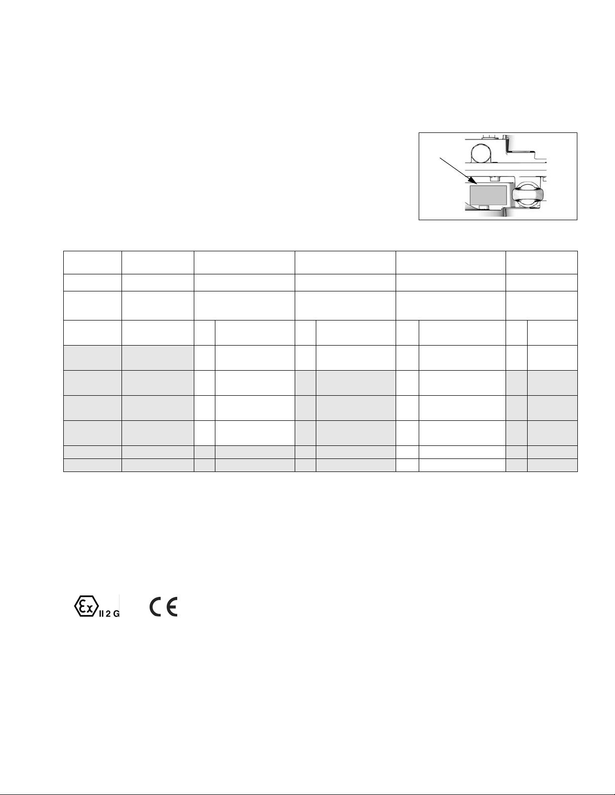
Check your pump’s identification plate (ID) for the 6-digit part number of your
pump. Use the following matrix to define the construction of your pump, based
on the six digits. For example, Pump Part No. EP2160 represents electric
power (E), pump (P), 230/460V motor (2), sensor circuit installed (1), 2000 cc
Maxlife lower (6), and no stand installed (0). To order replacement parts, see
the Repair-Parts manual 311594.
EP 2 1 6 0
First Digit Second Digit Third Digit Fourth Digit Fifth Digit Sixth Digit
Power
Source
E (electric) P (pump) 0 No motor 0 No circuit
Equipment
Style Motor Sensor Circuit Lower Size Stand Option
installed
1 230/400V, 5 HP,
AT EX
2 230/460V, 5 HP,
UL/CSA
3 230/400V, 3 HP,
AT EX
4 230/460V, 3 HP,
UL/CSA
1 Circuit installed 2 1500 cc Chromex 1 Stand
ID
ti8912a
ID Plate, Viewed from Above
1 1000 cc Chromex 0 No stand
installed
installed
3 2000 cc Chromex
4 1000 cc Maxlife
5 1500 cc Maxlife
6 2000 cc Maxlife
7 750 cc Chromex
Models
Pump Operational Limits
See Related Graco Manuals on the front cover.
Approvals
This equipment meets requirements of the following
approval agencies:
II2G EExdIIA T3
311596F 3
Glossary of Terms
Term Description
VFD Variable Frequency Drive
TDC Top Dead Center; measures position of pump
drive
I/O Input/output
Trip A condition which causes VFD to trip motor; see
page 24
PCB Printed Circuit Board
Pr Parameter
Run Set of commands enabling motor to run in desig-
nated direction
Stop Set of commands authorizing motor to stop run-
ning
Page 4
Overview
Overview
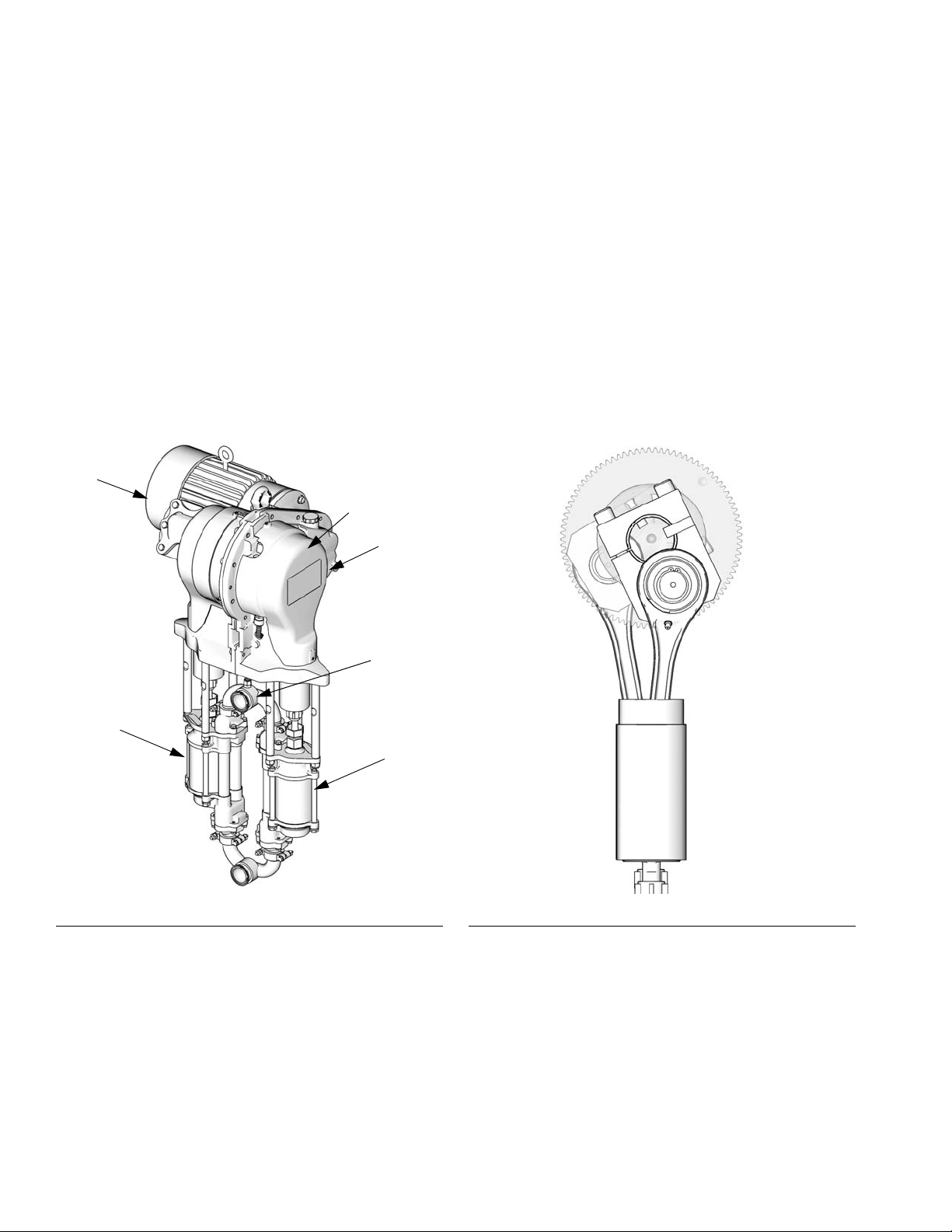
An electric motor (B) provides input to a 75:1 gear reducer (GR), which drives two fluid pumps (FP). See FIG. 1. The
stroke positions of the two pumps are offset to achieve consistent flow from the pump assembly. See F
The optional sensor circuit includes a top dead center (TDC) sensor which assists software in measuring motor
speed, and a pressure transducer (PT) with circuit board, which measures fluid pressure at the pump outlet. The
Graco VFD software mimics the effect of a camshaft, constantly adjusting motor speed to keep steady fluid flow and
achieve minimal pressure variation. The output shaft of the gearbox and the connecting rods experience the effect of
the imaginary camshaft by speeding up when the pressure drops (pump lower is at a changeover) and slowing down
when pressure increases (both lowers are pumping).
The VFD can be controlled by a local control box mounted in the hazardous area, via communication protocol (such
as modbus), or directly from the keypad.
IG. 2.
B
FP
F
IG. 1. Electric Circulation Pump
TDC (behind
cover)
GR
PT
FP
ti8317a
ti8321a
IG. 2. Cutaway Showing Offset Stroke Positions
F
4 311596F
Page 5

Variable Frequency Drive (VFD) Kits and Options
Variable Frequency Drive (VFD) Kits and Options
Kits and options can be ordered through your Graco Distributor.
Repair Kits
Transducer Kit P/N 15H876 - replaces the pressure
sensor and its circuit board. Note that pressure sensor
can be calibrated, and calibration procedure is included
in this manual.
Circuit Board Kit P/N 15H879 - replaces the sensor circuit board.
Top Dead Center Sensor Kit P/N 15H877 - replaces
top dead center (TDC) sensor.
Options
Ethernet Upgrade Kit P/N 15H885 - provides Ethernet
module for the VFD. Ethernet cable is not included.
Circuit System Kit P/N 15J755 - contains PCB and
sensors necessary to run Graco programmed VFD and
take advantage of low flow and pressure fluctuations
delivery by Graco software.
Local I/O Box P/N 120373 (UL/CSA) or 120991
(ATEX) - allows the operator to control the E-Flo locally
at the pump when performing maintenance or troubleshooting. The local I/O box has the following features:
• secure disable switch
• run/stop switch
• local/remote switch
• jog/park switch
•trip reset
Power Module P/N 288036- supplies necessary hardware to interface with the pump’s intrinsically safe (IS)
circuitry. The hardware includes IS barriers, transformer,
24 VDC power supply, fuses and terminal blocks for connectivity.
RFI Filter Module for 230 VAC VFD: P/N 120365
RFI Filter Module for 480 VAC VFD: P/N: 120366
VFD 200/240V Control Kit: P/N 15J753
VFD 380/480V Control Kit: P/N 15J754
311596F 5
Page 6

Controls and Indicators
Controls and Indicators
If Local mode of operation is an option for a given installation, use Graco Local I/O Explosion Proof Control Box
(see page 5).
Two Variable Frequency Drives are available and are
used for different voltages. Use the appropriate one for
your system. See front cover for part number information.
Control Modes
There are two ways to control or monitor the E-Flo Electric Circulation Pump.
• Locally
• Remotely (Keypad/Modbus)
The addition of a local control box allows the operator to
control the E-Flo at the unit. See Available Options on
page 5.
Starting, running, and stopping of the motor is controlled
by the Sequencer, which has been programmed to comply with E-Flo Local and Remote schemes. VFDs are
normally installed in electrical enclosures, away from
motors, which they control. Local mode refers to controls which are installed locally at the pump, or within
sight of the pump. Remote mode refers to controls
installed remotely, away from the pump.
More then one command is required to be active for
motor to operate. All of these are controlled by Graco
software. Do not try to reconfigure VFD parameters to
operate outside of the Graco design described in this
manual. Doing so can cause system malfunction.
Parameters are controlled by the program in the
AppsLite module and will be reset back to E-Flo defaults
at next reset. Reset occurs during each power-up.
Run command refers to a set of commands, enabling
motor to run in designated direction.
Stop command refers to a set of commands, authorizing
motor to stop running.
Local Control Mode
When Local mode is selected, motor can only be started
by a hardware switch. VFD terminal #27 is configured
for this operation (see System Electrical Diagrams,
page 42). Normally open position is Stop; closed posi-
tion is Run.
Common ground is available at VFD terminals #1,
3, 11, 21, 23, and 30.
Mode selection is performed by a hardware switch. Digital I/O #5 (VFD terminal #28) is configured for this operation (see System Electrical Diagrams, page 42).
Normally open position of the switch commands remote
mode; closed position commands local mode.
Common ground is available at VFD terminals #1,
3, 11, 21, 23, and 30.
6 311596F
Stop Command Via Keypad
To initiate the Stop command via the keypad, press the
Stop/Reset (red) button on a keypad display.
Remote Control Mode
When remote control mode is selected, control commands can be directly entered into the VFD by means of
a keypad or can be sent via modbus. Refer to SM Ethernet User Guide (Control Techniques) for more information on modbus control.
Page 7
Controls and Indicators
Variable Frequency Drive (VFD)
Keypad
The VFD keypad consists of a display, four control buttons, and a joypad with four arrow keys. See F
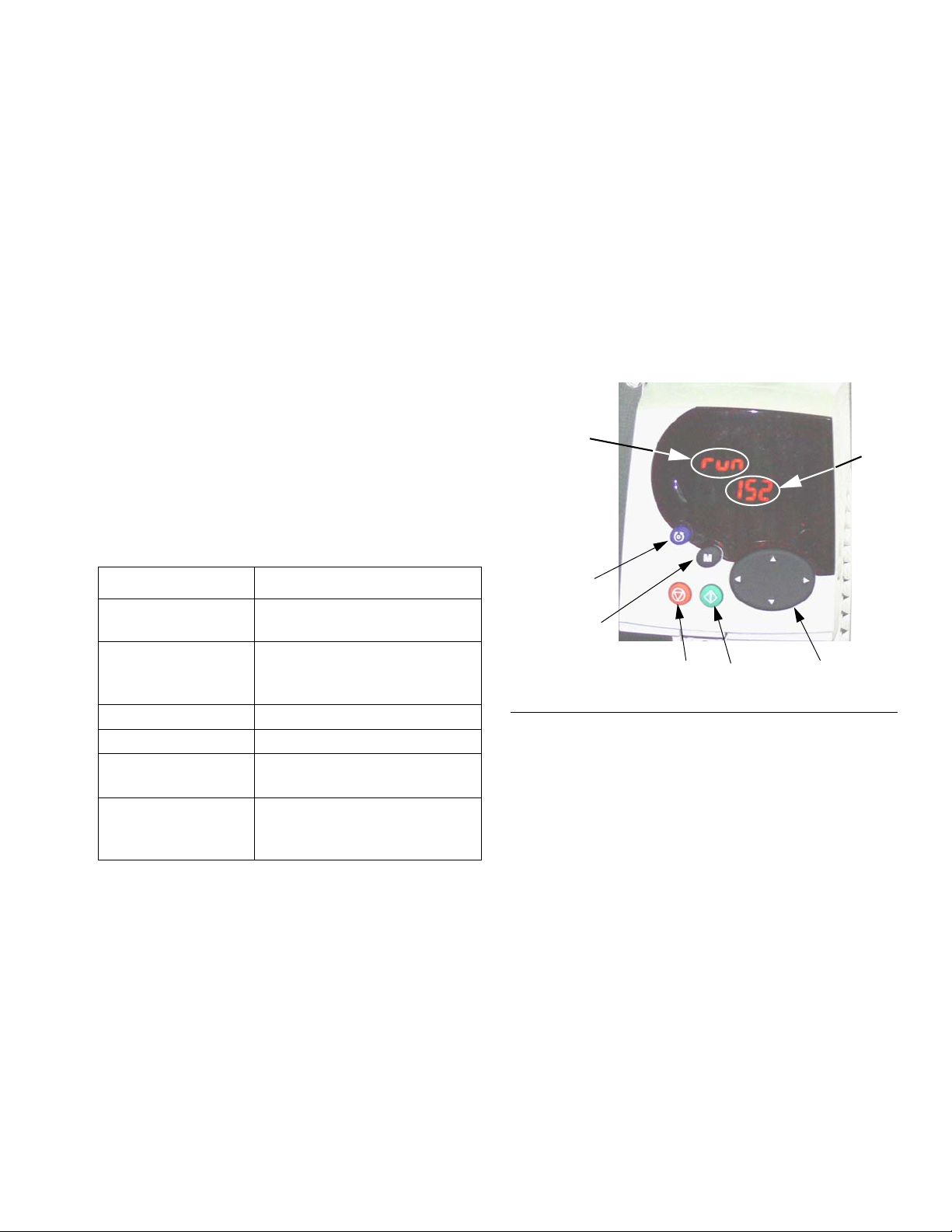
VFD Display
The VFD display has two rows.
The upper row (A) displays either the drive status (run is
shown) or the parameter being viewed, in the format
XX.XX (for example, 20.05). In this manual, parameters
are referred to as Pr (for example Pr 20.05).
The lower row (B) displays the parameter value (152 is
shown) or a trip code.
Table 1 shows some examples of drive status codes.
Refer to the User’s Guide by Control Techniques for the
full list.
Table 1: Drive Status Examples
IG. 3.
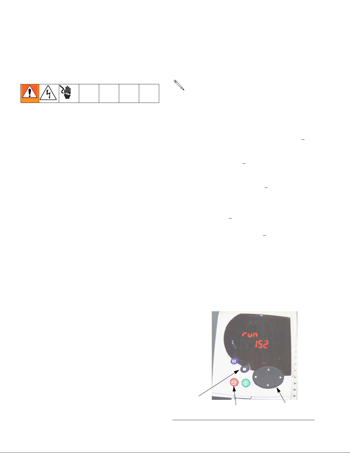
VFD Control Buttons
• Fwd/Rev (U): not active in this application.
• Stop/Reset (V)
• Start (I, green): not active in this application.
• Mode (M, black): used to change between the display modes - parameter view, parameter edit, status.
• Joypad: used to navigate the parameter structure
and change parameter values. See page 8 for
details.
A
B
Display Code Definition
Auto tunE
(flashes alternately)
inh VFD is inhibited and will not
rdY Motor is ready to run.
run Motor is running.
triP VFD has tripped. Trip code
dEC Decelerating - motor speed is
Motor auto tune is in progress.
run because Secure Disable
is engaged.
appears in lower display.
ramping to zero following a
stop command.
U
M
V
FIG. 3: Variable Frequency Drive Keypad
I
Joypad
311596F 7
Page 8
Setup
Setup
Ground the VFD
The equipment must be grounded. Grounding reduces
the risk of static and electric shock by providing an
escape wire for the electrical current due to static build
up or in the event of a short circuit. Ground the variable
frequency drive through a proper connection to a power
source. Refer to the Control Techniques manuals for
grounding instructions.
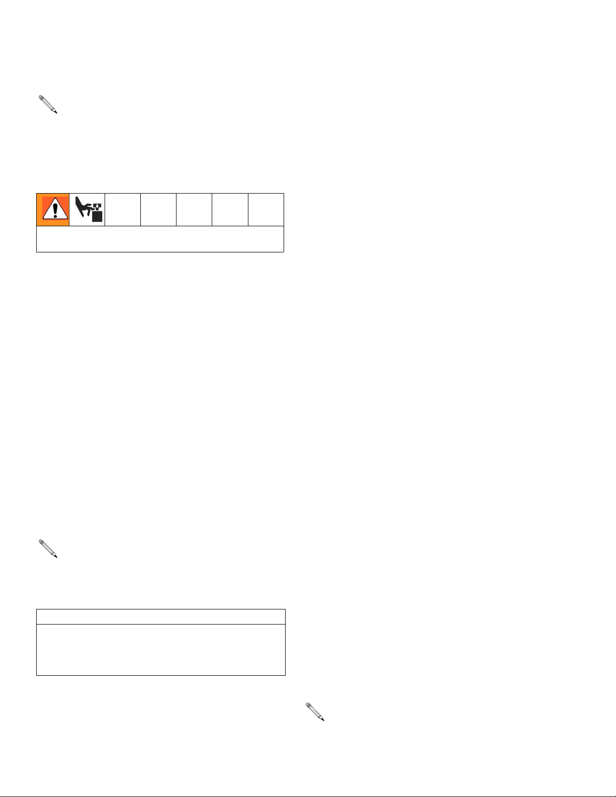
Navigating the Keypad
The Unidrive SP User Guide has a detailed explanation
of the Keypad operation and contains navigation procedures. The following is an example and is not intended
to explain in detail the complete operation of the Keypad. It is strongly recommended that the installer refer to
the Unidrive SP User Guide (provided on a CD) for
detailed instructions.
Calibration of lower size is chosen as an example to
explain the operation of the Keypad display. Graco
default setting for the lower size is 2000cc. In the following example, we will change the lower size to 1500cc.
2. Alter the value of Pr 20.03:
While number 20.03 is flashing on the upper row of
the screen, number 2000 is displayed on the lower
row of the screen, representing lower size of
2000cc.
a. Press the (M) key once. This will cause the cur-
sor to move to the bottom row of the display and
the least significant digit of the number 2000
(most right digit) should be flashing.
b. Press the Left arrow key to navigate to the third
digit from the right 20
to start flashing.
c. Press the Up arrow key to scroll to number 5.
This should cause number 25
screen with number 5 still flashing.
d. Press the Left arrow key to navigate to the next
digit on the left. This will cause number ‘2’ to
start flashing (2
e. Press the Down arrow key to change the num-
ber 2 to number 1. Number 1
played on a screen with number 1 flashing.
f. Press the (M) key once to move cursor from the
bottom row to the top row. This will cause number 20.03 on the top row to flash.
00. This will cause the digit
00 to display on a
500).
500 should be dis-
Each parameter consists of a menu number and submenu number. Lower size calibration value is located in
Pr 20.03: 20 refers to Menu 20; 03 refers to Submenu
03.
1. Navigate to Pr 20.03:
a. Pressing the Left and Right arrow keys will allow
you to navigate between menus 0 and 22.
b. Pressing the Up and Down arrow keys will allow
you to navigate within the submenus.
c. Press the Left or Right arrow keys until you
reach menu 20 (Number 20.00 should be flashing on a screen).
d. Press the Up or Down arrow keys until you
reach submenu 3 (Number 20.03 should be
flashing on a screen)
8 311596F
g. This completes the procedure of changing a
parameter value. In this case you have changed
Pr 20.03 from 2000 to 1500 (number 1500 will
show on lower row of display).
M
V
F
IG. 4: Variable Frequency Drive Keypad
Joypad
Page 9

E-Flo Calibration
CAUTION
The system must be calibrated before start-up. Failure
to calibrate will result in malfunction, alarm trips, and
decreased safety.
E-Flo Calibration
pressure performance for low flow settings (corresponding motor frequency of less than 12 Hz).
5. Continue with step 1. Pressure Sensor Calibration
on page 10.
Calibrate and Autotune the
Motor
IMPORTANT: Before installing the motor it must be
calibrated and autotuned. This allows the drive to
have better control of the motor.
Graco Motors
To calibrate and autotune motors purchased from
Graco, perform the following steps:
1. Motor Selection. Parameter Pr 20.37 is reserved
for the motor calibration information listed on the
pump’s identification plate. The value of Pr 20.37 is
determined as follows:
EP1XXX=> Pr 20.37 = 1
EP2XXX=> Pr 20.37 = 0
EP3XXX=> Pr 20.37 = 4
EP4XXX=> Pr 20.37 = 3
2. Load Graco Motor Defaults. Navigate to Pr 20.16
and set its value to 56. At this time the specific
Graco motor parameters will be loaded and the
number 56 will be replaced by 0 automatically.
3. Follow the instructions under Autotune the Motor,
page 10.
IMPORTANT: Autotuning the motor is especially
important if using a 3HP motor, or if a 5HP motor is
used on a system with a low flow setting (corresponding frequency of less than 12 Hz).
Non-Graco Motors
Graco does not support the use of the Graco VFD
CAM mode on motors not supplied by Graco.
Use only 1500 rpm or 1800 rpm rated motors.
To calibrate and autotune motors not purchased from
Graco, perform the following steps:
1. Motor Selection. Set Pr 20.37 to 2 (non-Graco
motor).
2. Set Motor Parameters. Navigate to menu #5. Refer
to your motor’s identification plate for necessary
information.
a. Pr 5.06 - Rated Frequency.
b. Pr 5.07 - Motor Rated Current.
c. Pr 5.08 - Rated Load RPM/Rated Speed.
d. Pr 5.09 - Rated Voltage.
e. Pr 5.10 - Rated Power Factor.
f. Pr 5.11 - Number of Motor Pole Pairs (4 pole
motor has 2 pairs).
3. Enter Motor Rated Current. Multiply motor rated
current found on motor’s identification plate by 10.
Enter resulting value into Pr 20.12.
4. Follow the instructions under Autotune the Motor,
page 10.
4. Pr 5.27 controls the Slip Compensation feature. It is
turned on by default for 3HP motors and turned off
for 5HP motors. Turning this feature on will improve
311596F 9
5. Continue with step 1. Pressure Sensor Calibration
on page 10.
Page 10
E-Flo Calibration
Autotune the Motor
IMPORTANT: Before installing the motor it must be
calibrated and autotuned. This allows the drive to
have better control of the motor.
Refer to the User’s Guide by Control Techniques for
complete autotuning instructions.
The motor shaft will rotate during autotuning. Keep
clear of moving parts.
1. Decouple motor from gearbox. Secure motor to prevent it from jumping during autotuning.
2. Apply power to motor. Motor will rotate during autotuning. Keep clear of motor shaft and moving parts.
3. Navigate to Pr 5.12 and set its value to 2.
4. Apply Run command, see page 22. Autotuning will
begin.
5. When motor stops turning, check that Pr 5.10
(Power Factor) and Pr 5.17 (Stator Resistance) are
set to non-zero values. This indicates that the autotune was successful.
To prevent accidental change of pressure sensor calibration parameters, they are locked by Pr 20.16. To
enter calibration parameters, perform the following
steps:
a. Set Pr 20.16 to 777, to unlock pressure sensor
parameters.
b. Select and set TDC and pressure transducer
function (software level 5.00.00 and later only):
• TDC: Pr 8.11. Select On (enable) or Off
(disable).
• Pressure Transducer: Pr 7.13. Select On
(enable) or Off (disable).
• Select Analog Signal Mode: Pr 7.11. Typi-
cally 4-20tr.
c. Enter calibration parameters Pr 20.34, 20.35,
and 20.36.
d. Set Pr 20.16 to 0 to lock parameters, then set
Pr 0.00 to 1001 to save parameters.
If pressure sensor is part of the system (EPX1XX –>
Fourth Digit = 1), calibration information is printed on the
label located on the circuit board cover. If the system
was purchased without a Circuit System Kit (Graco P/N:
15J755) but one was installed later, affix the label
(included with the kit) to the circuit board cover and
enter calibration information into the VFD.
6. To save motor parameters, navigate to Pr 5.00, set
its value to 1001, and press the red Stop/Reset button. The number 1001 will automatically change to
0, indicating that the parameters have been saved.
1. Pressure Sensor Calibration
IMPORTANT: Pressure sensor information for your
system is listed on the label attached to the pump
gearbox circuit board cover.
CAUTION
Pressure sensor calibration information must be
entered into the VFD. Failure to do so will result in
Pressure Sensor Calibration Trip (#50), nuisance
trips, or system malfunctions.
Pressure sensor information (Pr 20.34, 20.35, and
20.36) for your system must be keyed into the Vari-
able Frequency Drive before system start-up.
Calibration Parameters from the label:
Pr 20.34 – Zero Calibration
Pr 20.35 – Calibration Pressure
Pr 20.36 – High Calibration
2. Pump Lower Size Selection
Parameter Pr 20.03 is reserved for the Lower size calibration information listed on the unit’s identification
plate:
EPXX1X => Pr 20.03 = 1000
EPXX4X => Pr 20.03 = 1000
EPXX2X => Pr 20.03 = 1500
EPXX5X => Pr 20.03 = 1500
EPXX3X => Pr 20.03 = 2000
EPXX6X => Pr 20.03 = 2000
EPXX7X => Pr 20.03 = 750
If the pump lowers are changed to a different size
after purchase, the plate information is no longer
valid.
10 311596F
Page 11

E-Flo Calibration
3. Unit Selection
Select measuring units in parameter Pr 20.15. The
default is English.
English => Pr 20.15 = 0
Metric => Pr 20.15 = 1
Measurement unit summary:
Measurement English Metric
Pressure psi bar
Flow gpm lpm
The Keypad display does not show a decimal point.
T
ABLE 2 provides resolution values for measure-
ment setting parameters.
4. High Pressure Alarm Setting
The High Pressure Alarm setting is controlled by parameter Pr 20.09. The default unit is English and default setting is 300 psi. Refer to T
allowable setting for a given Lower size and units. The
High Pressure Alarm (#40) becomes active when system pressure reaches the pressure setting in Pr 20.09.
ABLE 2 to determine maximum
Low Pressure Alarm Disable => Pr 20.08 = 0
This feature is disabled by default.
6. Low Pressure Alarm Setting
The Low Pressure Alarm setting is controlled by parameter Pr 20.07. The default unit is English and default setting is 150 psi. Refer to T
allowable setting for a given Lower size and units. The
Low Pressure Alarm (#41) becomes active if it is
enabled (Pr 20.08 = 1) and system pressure drops lower
than the Low Pressure Alarm setting.
For metric units, multiply the desired pressure by
10 and enter the result into the VFD. The last digit
is a decimal.
System pressure must first rise above the Low
Pressure Alarm setting for the trip to start operating. This allows the system to build up to operating
pressure without shutting down due to Low Pressure Alarms.
ABLE 2 to determine maximum
7. System Ramp Rate Selection
For metric units, multiply the desired pressure by
10 and enter the result into the VFD. The last digit
is a decimal.
5. Low Pressure Alarm
Enable/Disable
Low Pressure is an adjustable feature. Parameter Pr
20.08 is used to enable and disable the feature:
Low Pressure Alarm Enable => Pr 20.08 = 1
Ramp rate controls the time it takes for the pump to
reach the preset rate. Units is English, measured in gallons per minute/minute (gpm/min). Note that a fast ramp
rate may cause the pump to rapidly build high system
pressure, causing system shutdown due to a High Pressure Trip (Alarm #40).
The Ramp Rate setting is controlled by parameter Pr
20.02. Ramp rate range is 10 – 1000 gpm/min. Any
number within this range can be selected. It is recommended that the default ramp rate be kept. The default
setting is 100gpm/min.
311596F 11
Page 12

E-Flo Calibration
8. Speed Potentiometer
Enable/Disable
Variable resistor (potentiometer) is used to control motor
frequency. Refer to Motor Speed Control, page 23, for
more information. Set Pr 20.38 to enable or disable the
speed potentiometer. Disable is the default.
• Speed Potentiometer Enable=> Pr 20.38 = 1
• Speed Potentiometer Disable=> Pr 20.38 = 0
9. Saving Calibration
The last step in the calibration procedure is to save all
calibration values.
a. Saving to the Drive/Program Module.
To ensure that all calibration values are permanently saved to the drive/program module:
1. Navigate to Pr 0.00 and set its value to
1001.
Factory Defaults
E-Flo System Specific Parameters (menu 20 parameters)
All of the E-Flo features are controlled by menu 20
parameters. VFDs are shipped with these parameters
set to default values (refer to Table 2 for more information). Factory defaults can be loaded as follows:
1. Disable the drive through Secure Disable (if a Graco
Local Control Box is used, press the red
mushroom-type Secure Disable button).
2. Navigate to Pr 20.16 and set its value to 1234. At
this time the program defaults will be loaded and
number 1234 will automatically be replaced by 0.
E-Flo Motor Specific Parameters
VFDs are shipped with all motor parameters defaulted to
UL/CSA motor. It is essential for system performance
that proper motor calibration parameters are entered
into the VFD. See page 9 for more information.
2. Press the red Stop/Reset button. The
number 1001 will automatically change to
0, indicating that all parameters have been
saved.
b. Saving to the SMARTCARD.
SMARTCARD is an excellent memory
backup for system-specific parameter calibrations. If system parameters are mistakenly
altered, using SMARTCARD can restore initial calibration.
1. Ensure that SMARTCARD is installed in
the VFD. (VFD is shipped with SMARTCARD already installed and Graco
defaults saved to memory location #101).
2. Navigate to Pr 0.00 and set its value to
4202 (memory location #202).
3. Press the red Stop/Reset button. Small
red dot on keypad display will start blinking, indicating that parameters are being
saved.
To restore factory defaults, set Pr 20.16 to 45.
SMARTCARD Defaults
Default Graco parameter values for menus 0 through 22
are saved on SMARTCARD in location #101, as differences from the drive defaults; see the Control Techniques manual for further information. Use Code 6101 to
load Graco defaults.
4. When dot stops blinking, the save is completed.
12 311596F
Page 13

E-Flo Calibration
Complete System Reload
A complete system reload may be necessary because
of an error in calibration or accidental parameter alteration.
1. Disconnect power to the VFD.
2. Remove all solutions modules. Reconnect power.
3. Navigate to Pr 0.00 and set its value to 1244.
4. Press the red Stop/Reset button. Number 1244 will
be automatically replaced by 0 as an indication that
all VFD parameters are reset to defaults.
5. Navigate to Pr 0.00, set its value to 1001, and press
red Stop/Reset button to save the changes. Number
1001 will be automatically replaced by 0.
6. Disconnect power from the VFD, reinstall all modules, and reconnect power. Reset any faults associated with solutions modules (VFD may not
recognize modules upon first power-up). Navigate to
Pr 0.00, set its value to 1001, and press red
Stop/Reset button.
7. Navigate to Pr 17.20 and set it to ON.
8. Navigate to Pr 17.21 and set it to ON.
9. Navigate to Pr 17.00, set its value to 1001, and
press red Stop/Reset button. Number 1001 will be
automatically reset to 0 as an indication that
changes have been saved.
10. Load system-specific calibration from the SMARTCARD (if saved at initial calibration).
a. Graco defaults are loaded as differences from
VFD defaults in memory location #101. Navigate to Pr 0.00, set its value to 6101, and press
red Stop/Reset button.
b. Recommended memory location for customer
calibration is #202. Navigate to Pr 0.00, set its
value to 6202, and press red Stop/Reset button.
11. If SMARTCARD is not available or if initial calibration was not saved to SMARTCARD, perform the following steps:
a. Load Graco system defaults - set Pr 20.16 to
1234.
Saving parameters will allow the VFD to retain
information associated with solutions modules.
b. Repeat E-Flo Calibration, beginning with Cali-
brate and Autotune the Motor on page 9 and
continuing with steps 1-9 of the calibration procedure (pages 10-12).
311596F 13
Page 14

E-Flo Features
E-Flo Features
Drive Active (System ON) Output
VFD Relay output is available at VFD terminals 41 and
42. The output can be mapped to most of the parameters. The most common is Drive Active. This relay output
will be closed when drive is active (there will be continuity between terminals 41 and 42). Pr 8.27 controls the
relay source. In case Drive Active is a desired source,
navigate to Pr 8.27 and set it to 10.02.
Pr 10.02 is a Drive Active indicator. See the Control
Techniques manual for further information.
Jog Mode
Jog mode allows the user to run the pump at the slow
speed and to stop it at a desired position. Note that park
angle allows easy access to the stand-side lower. Jog
mode can therefore be used to stop the pump at an
angle which will allow easy access to the motor-side
lower. Jog speed is equivalent to the following flow rates:
2000cc lowers: 2.7 gpm (10.2 lpm)
1500cc lowers: 1.9 gpm (7.3 lpm)
1000cc lowers: 1.4 gpm (5.4 lpm)
750cc lowers: 1.0 gpm (3.8 lpm)
Jog Mode in Local Control
Operation
To initiate Jog mode, press and hold the jog button. Jog
mode will stay active as long as the jog button is
pressed. When the jog button is released, the system
will stop.
Jog Mode - Keypad / Modbus Control
Parameter Pr 20.01 is allocated to control system
modes. Jog mode is mode #2. In order to initiate jogging, navigate to Pr 20.01 and set its value to 2. At this
time the system will enter the Jog mode.
When the pump has reached the desired position, stop
the system using one of the following methods:
• Put the system in Park by setting Pr 20.01 to 3, or
• Initiate the Stop command by using the red
Stop/Reset button or via Pr 20.25 (see Running the
Pump on page 21 for details).
IMPORTANT: Once system is stopped and jogging
is no longer required, change Pr 20.01 back to 0 to
revert to Cam mode.
Park Mode
Park mode allows you to park the pump in a position
allowing easy access to stand-side lower.
Hardware
Jog mode requires a momentary, normally open switch.
Graco offers a control box with jog switch installed. If
local control box is used and Local/Remote switch is set
to Local, jog mode can be initiated by pressing momentary “Jog” switch. Digital I/O #6 (VFD terminal #29) is
configured for the Jog mode (see System Electrical
Diagrams, page 42). Normally open (N.O.) position of
the switch disables jogging and closed position of the
switch (VFD terminal #29 connected to common)
enables jogging.
14 311596F
Park Mode in Local Control
Jog button has a dual function – Jog and Park. To
access the Park mode, press and release the switch in
less than 1 second.
Park Mode – Keypad / Modbus Control
Parameter Pr 20.01 is allocated to control system
modes. Park mode is mode #3. To initiate parking, navigate to parameter Pr 20.01 and set its value to 3. The
system will enter the Park mode. See Jog Mode instructions.
Page 15

E-Flo Features
Prime/Flush Mode
Prime/Flush mode allows system priming and flushing.
Once enabled, it commands the pump to run at the following flow rates for 2 minutes:
2000cc lower: 33.8 gpm (128.4 lpm)
1500cc lower: 24.3 gpm (92.3 lpm)
1000cc lower: 17.9 gpm (68.0 lpm)
Parameter Pr 20.40 enables and disables the
Prime/Flush mode.
Prime/Flush Enable => Pr 20.40 = 1 (Prime/Flush cycle
will start).
Prime/Flush Disable => Pr 20.40 = 0.
Notes:
1. Run the Prime/Flush mode with minimum flow
restriction.
2. Once Pr 20.40 is set to 1, the Prime/Flush cycle will
start and run for 2 minutes, at which time the pump
will stop. Pr 20.40 is automatically reset back to 0.
Back Pressure Regulator (BPR)
Control
BPR Production/Sleep modes – Keypad / Modbus
Control.
Digital I/O #3 (VFD terminal #26) is allocated for 24VDC,
0.5 W (maximum) solenoid.
Pr 20.18 enables and disables the solenoid output:
Pr 20.18 = 0: solenoid output disabled
Pr 20.18 = 1: solenoid output enabled
See System Electrical Diagrams on page 42 and
manual 311606 for wiring and installation details.
BPR Production/Sleep modes Graco E-Flo Control
The E-Flo program offers several BPR control features,
which are not available using the Keypad. See Com-
puter Control and Monitoring for more information.
311596F 15
Page 16

E-Flo Features
Cycle Counter
Two cycle counters are available: Grand Cycle counter
and Batch Cycle counter. Batch Cycle counter is a
resettable counter.
Grand Cycle Counter
Grand cycle counter is a non-resettable counter. First
four digits (XXXX9999) of the counter are located in
Pr 20.27. Next four digits (9999XXXX) are located in
parameter Pr 20.28.
Batch Cycle Counter
Batch cycle counter is a resettable counter. First four
digits (XXXX9999) of the counter are located in parameter Pr 20.29. Next four digits (9999XXXX) are located in
parameter Pr 20.30.
Batch Cycle Counter reset
Parameter Pr 20.26 resets Batch Cycle Counter when
set to 1.
Pr 20.26 resets to 0 automatically.
Pressure Monitoring
Average Pressure
Pr 20.31 displays average cycle pressure. It is a running
average of one full cycle. See T
tion.
For metric units, the last digit is a decimal.
Pressure Deviation
Pr 20.32 displays pressure deviation measured over one
full cycle. See T
For metric units, the last digit is a decimal.
ABLE 2 for more information.
ABLE 2 for more informa-
Flow Rate Monitoring
The average flow is displayed in Pr 20.17. Pr 20.15 is a
control parameter that allows the user to choose units
for measuring flow. If Pr 20.15 is set to 0, then units are
English and flow is displayed in gallons per minute
(gpm). If Pr 20.15 is set to 1, then units are Metric and
flow is displayed in liters per minute (lpm).
Pr 20.17 is an integer, and therefore it is not able to display decimal numbers. The last digit represents decimal
number. For example, if Pr 20.15 is set to 0 (English
units) and Pr 20.17 displays number 125, the flow
equals to 12.5 gpm (see T
Pump Displacement Volume
E-Flo Pump Volumes:
Lower Size
2000cc 4278 1.13
1500cc 3070 0.81
ABLE 2).
Volume per
Cycle (cc)
Volume per
Cycle (Gal)
1000cc 2263 0.60
750 cc 1537 0.41
16 311596F
Page 17

E-Flo Features
Yes
Load
Defaults ***Units
Mode)
0 (Cam
Default**
Pr
20.37 =
2
Pr
20.37 =
1 or 4
Pr
20.37
= 0 or
3
Pr
20.37 =
2
Pr
20.37
= 1 or
4
Low Limit High Limit
Pr
20.37
= 0 or
3
Res-
olu-
tion*
Units
Yes
100
[GPM/MIN]
Cus-
36.7 30.7
Cus-
3.8 6.1
LPM 0.1 N/A No
tomer
tomer
Pr
specific
Pr
Pr
specific
2
20.37 =
3,4
20.37 =
20.37
= 0, 1
150 [PSI] Yes
34.5 31.7 34.5
0
Bar 0.1
2
Pr
20.37 =
2
Pr
20.37
= 1 or
4
Pr
20.37
= 0 or
3
Pr
20.37 =
2
Table 2: E-Flo Calibration Parameters / Modbus Map
Pr
20.37
= 1 or
4
Low Limit High Limit
Pr
20.37 =
0 or 3
Reso-
lution*
English Units Metric Units
N/A N/A
0 = Cam
1 = Constant Speed
2 = Jog
Run Mode Selection
3 = Park
1 10 1000 N/A
MIN
GPM/
Ramp Rate
Selection
Lower Size
CC N/A 750 2000 CC N/A 750 2000 2000cc Yes
Selection (750cc,
1000cc, 1500cc,
2000cc)
Local/Remote
N/A N/A 0 (Local) 1(Remote) N/A N/A 0 (Local) 1(Remote) N/A N/A
Control Indicator
(Indicates position
of the Local/Remote
switch)
Flow Setting
Cus-
9.7 8.1
Cus-
1.0 1.6
1.4 2.4 14.3 11.9 5.3 9.1 54.1 45.0
GPM 0.1
750 cc Lowers
1000cc Lowers
tomer
specific
tomer
specific
1.9 3.2 19.4 16.2 7.2 12.1 73.4 61.3
2.7 4.5 27.1 22.6 10.2 17.0 102.6 85.6
1500cc Lowers
2000cc Lowers
Pr
Pr
Pr
20.37 =
= 3,4
20.37
20.37
= 0, 1
Low Pressure Alarm
Setting
500 460 500
0
PSI 1
1000cc Lowers 460 460 460 31.7 31.7 31.7
1500cc Lowers 350 350 350 24.1 24.1 24.1
2000cc Lowers 300 300 300 20.7 20.7 20.7
750cc Lowers
Low Pressure Alarm
Enable
N/A N/A 0 (Disable) 1 (Enable) N/A N/A 0 (Disable) 1 (Enable) 0 (Disable) Yes
0 = Disable
1 = Enable
20.02
Parame-
ter ID Function
20.01
20.03
20.04
20.05
20.07
20.08
311596F 17
Page 18

E-Flo Features
Load
Defaults ***Units
2
20.37 =
3,4
20.37 =
20.37
= 0, 1
2
20.37 =
= 3,4
20.37
300 [PSI] Yes
34.5 31.7 34.5
0
Bar 0.1
[A] 0.1 N/A No
N/A 0 N/A
Default**
20.37 =
2
20.37 =
1 or 4
= 0 or
3
20.37 =
2
= 1 or
4
= 0 or
3
olu-
tion*
Units
20.37 =
2
= 1 or
4
Pr
Pr
Pr
Pr
Pr
Pr
Pr
Pr
20.37
Pr
Pr
20.37
Low Limit High Limit
Pr
20.37
Res-
Pr
Pr
20.37
= 0 or
3
20.37 =
2
= 1 or
4
20.37 =
0 or 3
Reso-
lution*
Parame-
ter ID Function
Pr
Pr
20.37
Pr
Pr
20.37
Low Limit High Limit
Pr
English Units Metric Units
500 460 500
460 460 460 31.7 31.7 31.7
20.37
= 0, 1
High Pressure
Alarm Setting
350 350 350 24.1 24.1 24.1
0
PSI 1
1000cc Lowers
1500cc Lowers
750cc Lowers
20.09
300 300 300 20.7 20.7 20.7
2000cc Lowers
Motor Rated
Current x 10;
[A] 0.1
multiply motor rated
current listed on a
motor ID plate) by
10; for example,
I=6.5A, Pr20.12 =
20.12
08.8 08.8
0 15.5 0 15.5
N/A N/A N/A N/A N/A N/A 0 Yes
65
High Voltage Drive
Low Voltage Drive
Unit Selection (0 =
English, 1 = Metric)
Calibration (special
20.15
parameter)
1234 = Load
Defaults (resets
system related
menu 20
parameters to
Graco default
settings)
20.16
56 = Load Motor
Defaults (resets
motor related
parameters to
Graco default
settings)
777 = Unlock
pressure calibration
GPM 0.1 N/A LPM 0.1 N/A N/A N/A
parameters
20.17 Flow Indicator
18 311596F
Page 19

Pr
Pr
Load
Pr
20.37 =
Pr
20.37 =
20.37
= 0 or
Pr
20.37 =
20.37
= 1 or
E-Flo Features
Defaults ***Units
Default**
2
1 or 4
3
2
4
Low Limit High Limit
Pr
20.37
= 0 or
3
Res-
olu-
tion*
Units
Pr
20.37 =
2
Pr
20.37
= 1 or
4
Pr
20.37
= 0 or
3
Pr
20.37 =
2
Pr
20.37
= 1 or
4
Low Limit High Limit
Pr
20.37 =
0 or 3
Reso-
lution*
English Units Metric Units
N/A N/A 0 (Disable) 1 (Enable) N/A N/A 0 (Disable) 1 (Enable) 0 (Disable) Yes
CPM 0.1 N/A CPM 0.1 N/A N/A No
N/A N/A No
[A] 0.1 N/A [A] 0.1 N/A N/A N/A
N/A N/A 0 (Stop) 2 (Run) N/A N/A 0 (Stop) 2 (Run) 0 (Stop) Yes
N/A N/A 0 (Not Reset) 1 (Reset) N/A N/A 0 (Not Reset) 1 (Reset) N/A No
N/A 1 N/A N/A 1 N/A N/A N/A
N/A 1 N/A N/A 1 N/A N/A N/A
N/A 1 N/A N/A 1 N/A N/A N/A
PSI 1 N/A Bar 0.1 N/A N/A N/A
N/A 1 N/A N/A 1 N/A N/A N/A
BPR Valve Solenoid
Control
0 = Solenoid
Disable
1 = Solenoid Enable
Average Cycle Rate
Indicator
Graco defined
software version
major
Graco define
software version
minor
Average Motor
Current Indicator
(divide by 10)
Run/Stop
Command
0 = Stop
1 = Stop
2 = Run
Reset Batch Cycle
Counter
0 = Not Reset
1 = Reset
Grand Cycle Count -
First 4 places -
yyyy9999
Parame-
ter ID Function
20.18
20.19
20.20
20.21
20.24
20.25
20.26
20.27
Grand Cycle Count -
Next 4 places -
9999xxxx
20.28
Batch Cycle Count -
First 4 places -
yyyy9999
20.29
Batch Cycle Count -
Next 4 places -
9999xxxx
20.30
Average System
Pressure Indicator
20.31
311596F 19
Page 20

Pr
Pr
Load
Pr
20.37 =
Pr
20.37 =
20.37
= 0 or
Pr
20.37 =
20.37
= 1 or
Defaults ***Units
Default**
2
1 or 4
3
2
4
E-Flo Features
Yes
Motor)
0 (5 H.P. UL
Low Limit High Limit
Pr
20.37
= 0 or
3
Res-
olu-
tion*
Units
Pr
20.37 =
2
Pr
20.37
= 1 or
4
Pr
20.37
= 0 or
3
Pr
20.37 =
2
Pr
20.37
= 1 or
4
Low Limit High Limit
Pr
20.37 =
0 or 3
Reso-
lution*
English Units Metric Units
PSI 1 N/A Bar 0.1 N/A N/A N/A
N/A 1 N/A N/A 1 N/A N/A N/A
PSI 1 100 500 Use English Units to calibrate N/A N/A
N/A 1 0 N/A N/A 1 0 N/A N/A N/A
N/A 1 0 N/A N/A 1 0 N/A N/A N/A
N/A 1 0 4 N/A 1 0 1
N/A N/A 0 (Disable) 1 (Enable) N/A N/A 0 (Disable) 1 (Enable) 0 (Disable) Yes
N/A N/A 0 (Disable) 1 (Enable) N/A N/A 0 (Disable) 1 (Enable) N/A Yes
Control Enable
0 = Disable
1 = Enable
Prime/Flush Enable
(Special parameter,
returns to Disable
state once flushing
is complete)
0 = Disable
Pressure Sensor
Error Indicator
(used for
calibration)
Zero Point
Calibration
System Calibration
Pressure
High Point
Calibration
0 = 5 H.P. UL Motor
1 = 5 H.P. ATEX
Motor
2 = Customer Motor
3 = 3 H.P. UL Motor
4 = 3 H.P. ATEX
Motor
Motor Select
20.32 Pressure Range
Parame-
ter ID Function
20.33
20.34
20.35
20.36
20.37
Analog Input Speed
20.38
20.40
1 = Enable
Pr 20.17 is showing a number 157, while English units are selected. Last digit 7 is a decimal, which means that the flow is 15.7 GPM.
* Resolution: Note that the Keypad display does not utilize a decimal point. Last digit of a variable with a resolution of 0.1 is a decimal. For example, flow indicator
**Default: All calibration parameters have a default setting. Drives are shipped out from Graco with all calibrations set to their defaults. Use Pr 20.16 to reload default.
***Load Defaults: Yes indicates that a default value will be loaded if Load System Defaults is triggered (Pr 20.16 = 1234).
20 311596F
Page 21

Running the Pump
Operational Envelope Limit
Explosion-proof electric motors have constant torque
and variable torque limits. E-Flo system is a constant
torque application, and therefore the motor’s constant
torque limits must not be violated. The system is available with two motors: the UL/CSA explosion-proof motor
and the ATEX explosion-proof motor. To stay within the
allowed torque, flow and pressure limits are installed.
Flow Limit
Speed command is limited to 5:1 operation for ATEX
motors and 10:1 operation for UL/CSA motors. 5:1 dictates a frequency of 10 Hz minimum to 50 Hz maximum.
10:1 dictates a frequency of 6 Hz minimum to 60 Hz
maximum.
See T
ABLE 2 for flow limits (Pr 20.05).
Pressure Limits
Operating pressure limits are unique to the pump lower
sizes. If the system pressure is greater than the maximum allowed for a given pump lower size for longer than
30 seconds, system Trip #44 will shut the system down.
See T
ABLE 3 for system pressure limits.
Running the Pump
CAUTION
The drive has been programmed by Graco. Do not
attempt to recalibrate the Sequencer or Motor Control
as it can interfere with the Graco Program.
Secure Disable
According to Control Techniques Unidrive SP User
Guide, “Secure Disable (SD) function provides a means
for preventing the drive from generating torque in the
motor, with very high level of integrity”. This hardware
function controls enable/disable state of the drive.
Secure Disable/Drive enable hardware input (VFD terminal #31) is designed for positive logic input only. It
should be connected to internal 24VDC power supply
(VFD terminal #22). The SD is a fail-safe function; it
enables the drive when 24VDC is connected to SD
hardware input and disables (inhibits) the drive when SD
hardware input is open.
Pr 6.29 and Pr 8.09 can be used to monitor state of the
Hardware enable input.
Table 3: System Pressure Limits
Non-Graco
Lower
Size
(cc)
2000 250 17.2 250 17.2
1500 330 22.8 330 22.8
1000 460 31.7 460 31.7
750 425 (if set
Graco Motor
(Pr 20.37 = 0, 1, 3, or 4)
psi bar psi bar
29.3 (if set
to 3 or 4);
500 (if set
to 0 or 1)
to 3 or 4);
34.5 (if set
to 0 or 1)
Motor
(Pr 20.37 = 2)
500 34.5
Local I/O Box (see page 5) provides a normally closed
Secure Disable switch, which has a red mushroom-type
button (press to latch, pull to unlock). When latched,
switch opens SD circuit, therefore disabling (inhibiting)
the drive. When unlocked, switch closes SD circuit,
enabling the drive.
311596F 21
Page 22

Running the Pump
Start/Stop Command
Local Control Mode
When Local mode is selected, Run command can only
be initiated by means of Run/Stop hardware switch – set
Run/Stop switch to Run position.
Stop command can be initiated by one of the following:
1. Run/Stop switch:
Set Run/Stop switch to Stop position.
2. Stop/Reset button:
Press Stop/Reset (red) button on a VFD Keypad
display. Note that if Stop command was initiated by
pressing Stop/Reset button, one of the following two
actions will restart the pump:
a. Cycle the Run/Stop switch – Set it to Stop posi-
tion and then to ‘Run’ position.
b. Cycle Secure Disable circuit.
3. Secure Disable circuit:
Disable the drive by disconnecting SD circuit. Note
that if motor is stopped by means of SD circuit while
Run/Stop switch was in Run position, the Run command will be reapplied once SD circuit is reconnected.
Remote Control Mode
Run command can be varied via Keypad only if
Local/Remote switch is set to Remote.
To initiate Run command via Keypad, navigate to Pr
20.25 and set its value to 2.
Stop command can be initiated by one of the following:
1. Red Stop/Reset button on a keypad:
Press Stop/Reset (red) button on a VFD Keypad
display. If Stop command was initiated by pressing
Stop/Reset button, one of the following two actions
will restart the pump:
a. Set Pr 20.25 to 1 and then to 2.
b. Cycle SD circuit.
2. Navigate to Pr 20.25 and set its value to 1 or 0.
22 311596F
Page 23

Running the Pump
Flow Control
Motor Speed Control
Motor speed is set indirectly, by setting Pump Flow
Rate, which is then translated to motor speed by Graco
Software.
Motor Speed is set via Preset Reference 1. Refer to
Unidrive SP User Guide, Menu 1: Frequency / Speed
Reference Logic Diagram.
Local Mode
Resistance of 0 ohms corresponds to zero flow.
Increase in resistance causes increase in flow. Use Pr
5.01 to monitor instantaneous speed of the motor (in
Hz).
Hardware required – 5 k ohm Variable Resistor (Potentiometer). Refer to Control Technique Unidrive SP User
Guide for more details on electrical installation (also see
System Electrical Diagrams, page 42).
3. Enter the result into parameter Pr 20.05 (enter num-
ber 120).
See TABLE 2 for flow limits.
Speed Potentiometer control mode is available if the following conditions are valid:
1. Speed Potentiometer Enable = (Pr 20.38 = 1).
2. Control Mode = Local (Local/Remote switch in Local
position; Digital I/O #5 (VFD terminal #28) is
grounded (Common ground is available at VFD terminals #1, 3, 11, 21, 23, and 30).
Remote Mode
In this mode the speed potentiometer mode has no
effect even if enabled.
To have a remote control, the following condition must
be true:
VFD
Internal 10 VDC
Differential Analog Input (+)
Differential Analog Input (-)
Common Ground
IG. 5
F
4
5
6
1
RUN/STOP
SPEED POT
(5 k ohm)
If Speed Potentiometer is not installed, flow can be controlled directly from the Keypad. The following conditions
must be true:
1. Speed Potentiometer Enable = Disable (Pr 20.38 =
0).
2. Control Mode = Local (Local/Remote switch in Local
position; Digital I/O #5 (VFD terminal #28) is
grounded (Common ground is available at VFD terminals #1, 3, 11, 21, 23, and 30).
Enter desired flow into Pr 20.05 as follows (example
shown is in English units):
Control Mode = Remote (Local/Remote switch in
Remote position; Digital I/O #5 (VFD terminal #28) is
floating.
Flow is controlled by the Pr 20.05.
Multiply desired flow value by 10 (see Local Mode
above and T
ABLE 2 for more details).
1. Determine desired flow (for example, 12 gallons per
minute [gpm]).
2. Multiply desired flow by 10 (12gpm*10 = 120gpm).
311596F 23
Page 24

Diagnostics
Diagnostics
Drive Trip Codes and Diagnostic
Procedures
Drive status and trips are located in Menu 10. Drive trips
are stored in Pr 10.20 through Pr 10.29. For more information on trip and diagnostic procedures refer to Control Technique Unidrive SP Advance User Guide.
Trips and Diagnostic
Procedures
System trips with values in the range of #40 – 50, and
trip 100 are E-Flo specific.
Trips #40 – 50 will cause the system to shutdown upon
becoming active. Trip 100 is reserved for a system alarm
reset.
An external trip is also configured specifically for E-Flo;
its trip code is Et. This trip becomes active if one of the
following conditions is true:
• Power is applied to the motor while Secure Disable
circuit is connected (normally closed switch is
closed, indicating Drive Enable). It is therefore recommended to disable the drive by disconnecting the
Secure Disable circuit (normally closed switch is
open) before applying power to the motor.
• VFD/Apps module(s) reset is initiated while drive is
enabled (Secure Disable circuit is connected). It is
therefore recommended to disable the drive before
performing system reset,
Refer to the Control Technique User Guides for trip
codes which are not listed in T
ABLE 4.
Resetting the System
1. Stop the pump.
2. Disable the drive by disconnecting the Secure Disable circuit.
3. Navigate to Pr 0.00 and set its value to 1070. Press
the red (reset) button. Note that the system will reset
at this time. Value of Pr 0.00 will be reset back to 0
automatically.
24 311596F
Page 25

Table 4: Trips and Diagnostic Procedures
Trip
Code Trip Description Diagnostic
Diagnostics
40 High System Pressure
(System pressure is higher
than the allowed maximum)
41 Low System Pressure
(System pressure is lower
than the allowed minimum)
42 No TDC (Top Dead Center
Sensor is not detected)
43 High Motor Current
(Motor current has
exceeded the maximum for
the duration of 30 seconds)
1. Check High Pressure Alarm setting (Pr 20.09). Verify that system
desired operational pressure is lower then High Pressure Alarm setting.
2. Check for flow restrictions (closed valves, unexpected restrictions).
3. Check pump fluid section for proper operation (piston seals, ball
checks). Refer to pump maintenance manual for additional information.
1. Check Low Pressure Alarm setting (Pr 20.07). Verify that system
desired operational pressure is higher then Low Pressure Alarm setting.
2. Check fluid level. Low fluid level will cause system to run at low pressure.
3. Check fluid supply to the pump.
4. Check pump fluid section for proper operation (piston seals, ball
checks). Refer to pump maintenance manual for additional information.
1. Verify that output shaft is turning.
2. Check all of the wiring.
3. Verify that sensor is operational. Remove PCB cover and monitor LED
light on a top of the sensor. The light should be normally on and it
should be off for only short period of time when top dead center is
reached.
1. Check motor calibration Pr 20.37 (UL/CSA. motor is 0 and ATEX motor
is 1).
2. Check torque on both throat-packing nuts (see lower repair-parts manual 311690).
3. Flow/Pressure combination may be set too high for a given fluid/system.
44 Operational Envelope
(System has operated outside of operational window
for the duration of 30 seconds)
1. Check system pressure setting. Ensure that system pressure does not
exceed the allowed operational envelope. Refer to Operation Manual
311593 for Motor Speed and Flow Charts and to Operational Enve-
lope Limit on page 21.
2. Check pressure sensor calibration. If sensor needs to be recalibrated
follow instructions, page 41.
311596F 25
Page 26

Diagnostics
Table 4: Trips and Diagnostic Procedures
Trip
Code Trip Description Diagnostic
45 Motor Stalled This trip occurs when the motor is not able to develop torque, and therefore
cannot put the pump into motion.
1. Relieve system pressure.
2. Check lowers, slider cylinders, and output shaft with connecting rods for
visible damage. If no damage is visible, check for excessive heat which
is a sign of friction.
3. Check motor wiring.
4. Disconnect lowers and try running just the motor and gearbox.
49 Runtime Trip 1. Reset the system (see directions on page 24).
2. Cycle power.
3. Perform Complete System Reload, page 13.
50 Pressure Calibration Enter proper pressure sensor calibration parameters, page 9.
Et External Trip Open Secure Disable circuit and reset the trip.
CL2 Loss of Pressure Sensor 1. Ensure that pressure sensor wiring is installed as shown in F
2. Ensure that pressure sensor shield is grounded. Use PCB terminal J3-3
as shown in F
IG. 29. Do not ground the shield at both ends.
3. Check wiring and power to the barrier.
4. Check pressure transducer current (VFD terminal #7). The pressure
transducer current range should be 4-20 mA.
IG. 29.
26 311596F
Page 27

Computer Control and Monitoring
Computer Control and
Monitoring
To control or monitor the system using the supplied software with a computer (PC), the following components
are required:
• Graco VFD, Part No. 15J753 or 15J754
• Ethernet Upgrade Kit 15H885
• Category 5 Ethernet Cable
To control the pump using a computer, the system must
be in remote mode and the SECURE/DISABLE switch
must be disabled.
To monitor the pump from a computer, the system must
be in local mode.
Ethernet Upgrade Kit 15H885
The Ethernet Upgrade Kit includes a module which
allows a computer to monitor/communicate with the
VFD via Ethernet. See manual 311612 for installation
instructions.
2. Download Winflasher III from the Control Techniques website.
3. Connect CT COMM Cable to RJ45 serial interface
connector in the front of the VFD.
If the Ethernet module is installed it must be disabled to allow serial communication.
4. Disable the Ethernet Module (if installed) as follows.
a. Navigate to Pr 16.37 and set its value to OFF.
b. Save all parameters: Navigate to Pr 0.00, set its
value to 1001 and press the red Stop/Reset button. Wait until number 1001 changes to 0 automatically as an indication that changes have
been saved.
c. Cycle power to the VFD. This is necessary to
activate serial communication after the Ethernet
module has been disabled.
5. Update the software as follows:
a. Launch winflash.exe (Winflasher III program).
E-Flo Software Update
The following components are required to update E-Flo
software:
Hardware
• CT COMM Cable
Software
• CT SOFT and Winflasher
Installation Instructions
1. Connect to Control Techniques website and download CT SOFT (http://www.control techniques.com
CT SOFT is a free program, but must be registered
with Control Techniques.
).
F
IG. 6
311596F 27
Page 28

E-Flo Software Update
b. Read information in the Introduction window
and select Next.
F
IG. 7
c. Choose “Download a compiled program” option
and select Next.
d. Browse for a Graco software file and select
Next.
FIG. 9
e. Select the method for downloading: In the
“Select the method for downloading” window
under “Connection Protocol”, select CT-RTU
(Unidrive SP). Under “Settings” choose Slot 3.
Ensure that the correct communication port is
selected. Use the “Change Communications
Settings” button to change the port assignment.
Select Next.
IG. 8
F
IG. 10
F
28 311596F
Page 29

E-Flo Software Update
f. Read the Important Safety Warning and select
Next.
F
IG. 11
g. Press the red button to begin the download.
h. Wait for download to finish. Do not disconnect
power while downloading as it may cause damage to the equipment. When the download has
ended, select Finish to exit the program.
FIG. 13
If the Ethernet module is used it must be
re-enabled to allow serial communication.
6. Re-enable the Ethernet Module (if used) as follows.
a. Navigate to Pr 16.37 and set its value to ON.
b. Save all parameters: Navigate to Pr 0.00, set its
value to 1001 and press the red Stop/Reset button. Wait until number 1001 changes to 0 automatically as an indication that changes have
been saved.
IG. 12
F
311596F 29
Page 30

E-Flo Software Update
Configure the Ethernet Card
To configure the Ethernet card for proper access
manually set the IP address rather than allowing
the PC to automatically do so. These procedures
are written for a Windows XP operating system.
1. Go to Start>Control Panel.
2. Select Network Connections.
3. Select the icon for the network connection you will
be using to communicate with the VFD, right click on
the icon, and select properties. See F
IG. 14.
FIG. 15
F
IG. 14
4. The Local Area Connection Properties window will
open. Select Internet Protocol from the listed
options. Click on Properties. The Internet Protocol
Properties window will appear. See F
IG. 15.
30 311596F
Page 31

E-Flo Software Update
5. See FIG. 16. Select “Use the following IP address.”
The default Pump IP address is 192.168.1.100.
Enter a number which differs from the default
address in only the last set of numbers, for example:
192.168.1.10. This enables the computer to connect
to the VFD. Set Subnet mask to 255.255.255.0.
Install the Computer Software
Load the supplied CD into your computer and follow the
software installation instructions as they appear on the
screen.
Once the installation is complete, select E-Flo from the
Windows Start menu.
Graco uses a Visual Basic program to display the
run screen on the computer. This software and
program is not supported by Graco.
Connect the VFD to the PC
Use a CAT 5 Ethernet Cable (D) to connect the VFD
Ethernet Module (C) to the PC. See F
IG. 17.
IG. 16
F
6. Press OK.
It may take 30-60 seconds for the computer to
locate the address and establish the connection.
F
IG. 17
C
D
311596F 31
Page 32

E-Flo Software Update
Connecting to Multiple VFDs
Connecting to multiple VFDs requires that each VFD
must have an individual Ethernet upgrade kit. Furthermore, a router is probably necessary to allow one
instance of the Visual Basic software to control all
drives. The following steps describe the correct procedure to set up numerous connections:
1. Connect an Ethernet cable from each module to the
router and also from the router to PC.
2. Open the VB application and press Connect. See
F
IG. 18.
F
IG. 18
3. Click CONNECT. See F
appears. See F
IG. 22. The Network Setup window
will close when connection is made.
IG. 19. The Run screen
Multiple run windows should now appear. To connect to
each drive, the IP Address of each drive must be
unique. To accomplish this, navigate to drive parameter
#16.13 on each drive and increment this such that each
pump contains a different value. For example:
Drive 1: Par. #16.13 = 100
Drive 2: Par. #16.13 = 101
Drive 3: Par. #16.13 = 102
Drive 4: Par. #16.13 = 103
After doing this on each drive, each drive must be reset.
See Resetting the System, page 24, for instructions.
7. Repeat steps 2 and 3 for each additional IP address
you selected in step 5 on page 31.
At this point, go to the software again, and press the
Connect button on the main run window and then, in the
Network Address Setup window, enter the new IP
address.
4. In the main run window, go to Options>Add or
Change Pump Info.
5. Enter the new pump information. See F
IG. 20.
Check the boxes next to each connected drive.
Press Button to
Connect
IG. 19. Network Address Setup Window
F
Default Pump IP
Address
6. Select Save Settings and then select Open Selected
Pumps.
F
IG. 20 Multiple VFD Connections
32 311596F
Page 33

E-Flo Software Update
Run Screen
Speed Control
Graco uses a Visual Basic program to display the
run screen on the computer. This software and
program is not supported by Graco.
See FIG. 22. The sliding scale on the Run screen sets
the pump speed in units of flow.
To change units of measure (English/Metric), select
Options menu, then Advance Options screen (see
page 35).
In remote mode, the slider is active and can be controlled on the computer. Select the slider with the cursor
and move it to the desired value on the scale.
In local mode, the slider cannot be controlled on the
computer. It will independently move up and down the
scale, reflecting average flow as measured by the VFD.
• To stop the pump, press STOP. The button display
will change to STOPPED, and the RUNNING button
display will change to RUN.
PARK ON/OFF Button
• PARK ON sets the pumps to the park position.
• PARK OFF turns off the park feature and resumes
normal operation.
Trip Reset Button
Trip button becomes enabled (active) when Secure Disable is pressed.
Press to reset the pump if a trip occurs.
BPR Button
• BPR IN PRODUCTION: use in normal production
mode.
• BPR IN SLEEP: when no production.
Counters
See FIG. 22. The counters are active in both remote and
local mode.
Pressure - Displays fluid pressure reading from
pressure transducer.
Flow Rate - Displays flow per minute.
CPM Rate - Displays pump cycles per minute reading
from TDC sensor.
Batch Counter - Displays batch cycle count. User
resettable; see Reset Batch Counter, page 35.
Cycle Count - Displays total cycle count. Not resettable.
Control Buttons
See FIG. 22. In remote mode, the buttons are active and
may be used to control the pump.
RUN and STOP Status Buttons
The status buttons operate as a toggle switch to run or
stop the pump.
Set the speed (flow) to the desired level for sleep
mode and the system will slow down when BPR
OUT OF PRODUCTION button is pushed.
Access the Advanced Options Screens
From the Run screen (FIG. 21) go to the Options
pull-down menu. Select the Advanced Options Screen
(page 35). From the Advanced Screen the Data Log-
ging Screen (page 39), or Power Monitor Screen
(page 40) can be selected.
F
IG. 21
• To run the pump, press RUN. The button display will
change to RUNNING, and the STOPPED button display will change to STOP.
311596F 33
Page 34

E-Flo Software Update
Run Screen
To access
Advanced/Data Logging/
Power Monitor Screens
To reset Batch
Counter
Fluid Pressure
Flow Rate
CPM Rate
Batch Counter
Cycle Count
RUN Status Button
STOP Status Button
PARK ON/OFF Button
Trip Reset Button
BPR In Production
Button
Sliding Speed
Control
Record of trips
FIG. 22. Run Screen
34 311596F
Page 35

E-Flo Software Update
Advanced Options Screen
The advanced screen allows user changes to operating
parameters. This is only effective in the remote mode.
See F
IG. 24.
Units of Measure
Select desired units (English or Metric). See FIG. 24.
Values on Run screen will change accordingly.
Trips
• High Pressure Trip: Default is 300 psi. If measured
pressure is more than the set pressure, a high pressure trip will occur. See T
20.09.
• Low Pressure Trip: The low pressure trip is an
optional setting. To set, select the low pressure trip
box and input the desired value. If measured pressure is less than the set pressure, a low pressure
trip will occur.
ABLE 2 on page 17, Pr
Flow Calibration
Lower Size: Select size of pump lowers (750cc,
1000cc, 1500cc, or 2000cc).
Trend Timer
Trend timer is used for a timeline management for data
logging. Set desired trend time (1 to 5 seconds) or (1 to
5 minutes).
CAM
• CAM: CAM is the default. This setting utilizes the
E-Flo cam profile which eliminates pressure fluctuations by adjusting motor speed incrementally.
• Constant Speed: Sets motor to a constant speed,
which negates the cam profile and may result in
pressure fluctuations.
Reset Batch Counter
Press to reset batch counter on Run screen.
System pressure must first rise above the Low
Pressure Alarm setting for the trip to start operating. This allows the system to build up to operating
pressure without shutting down due to Low Pressure Alarms.
311596F 35
Page 36

E-Flo Software Update
Drive Status Messages
There are two groups of drive status messages:
• Drive Health
• Drive Warning Messages
An active status message will turn red. See T
page 38 for additional information.
ABLE 5 on
Prime/Flush
Prime/flush allows system priming and flushing. Once
enabled, the pump will ramp up to the following flow
rates for two minutes.
• 2000 cc lower: 33.8 gpm (128.4 lpm)
• 1500 cc lower: 24.3 gpm (92.3 lpm)
• 1000 cc lower: 17.9 gpm (68.0 lpm)
• 750 cc lower: 12.2 gpm (46.2 lpm)
BPR Production Flow Screen
BPR Production Flow Screen
is accessed from the options
menu in main screen
FIG. 23 BPR Production Flow Screen
36 311596F
Page 37

Advanced Options Screen
Selecting the Auto/Setup displays the BPR Screen shown in FIG. 25.
E-Flo Software Update
Set Trend Time
Set desired units
of measure
Set high and low
pressure limit,
and low pressure
trip, if desired
Set size of lower
Reset batch
counter
Record of Trips
FIG. 24
Set BPR
Auto Mode
Prime/Flush
Drive
Status
Messages
Return to Run
Screen
BPR Timer Screen
Select Production
Select (De)Activation
Times
Select Sleep Flow Rates
F
IG. 25
Days
311596F 37
Page 38

E-Flo Software Update
Direction Commanded True 10.13
Braking IGBT ActiveBraking 10.11
Running at or Below Min. Speed 10.04
Direction Running True 10.14
Over Temperature Alarm 10.18 Motor overtemperature switch activated.
Under Voltage Active 10.16
Braking Resistor Alarm 10.12
Output is at Current Limit 10.09
Table 5: Drive Status Messages
Message Parameter ID Description
DRIVE HEALTH MESSAGES
Drive Healthy 10.01 Drive is not tripped.
Drive Active 10.02 Drive is active.
At Speed 10.06 Motor is rotating.
Load Reached 10.08
Regenerating 10.10
Drive at Zero Speed 10.03
DRIVE WARNINGS MESSAGES
Drive Warning 10.19 There is an active drive alarm (10.18,
10.17, or 10.12).
Overload Alarm 10.17
Mains Loss 10.15 Loss of input power.
Above Set Speed 10.07 Unit is running faster than set speed
range.
Below Set Speed 10.05 Unit is running slower than set speed
range.
38 311596F
Page 39

E-Flo Software Update
Data Logging Screen
The data logging screen records pressures, speed,
time, and ranges.
1. Press Start Data Logging button.
Begin data logging
2. Default filename is LogFile.CSV. Enter the desired
filename.
3. Pressing Start Data Logging will begin logging, and
indicator will start moving.
4. Press Stop Data Logging to complete and close file.
Record of Trips
Return to Run Screen
F
IG. 26. Data Logging Screen
311596F 39
Page 40

E-Flo Software Update
Power Monitor Screen
The Power Monitor screen displays motor status in Hz, Amps, and horsepower.
To zoom in on the graphs, select one of the sliders on an axis and slide it toward the other on the same axis.
Press Clear button to restart graph information.
Motor Speed (Hz)
Record of Trips
Motor Power (HP or KW)
Motor Current (Amps)
Clear
F
IG. 27. Power Monitor Screen
40 311596F
Return to Run Screen
Page 41

Pressure Transducer Calibration Procedure
Pressure Transducer Calibration Procedure
E-Flo pressure sensor must be calibrated against an
instrument grade High Precision Pressure Transducer,
which should be installed near the E-Flo pressure sensor.
1. Ensure that the High Precision Pressure Transducer
calibration is up to date.
2. Set Pr 20.16 to 777, to unlock pressure sensor
parameters.
3. Calibrate Low Pressure Point as follows:
a. Ensure that system is not pressurized. Calibra-
tion instrument pressure reading should be 0
psi.
b. Use Keypad to navigate to Pr 20.33; monitor its
reading for 5 – 10 seconds to determine its
average value. Make a record of it.
c. Navigate to Pr 20.34 and enter the recorded
average value of Pr 20.33.
4. Calibrate the High Pressure Point as follows:
a. Pressurize the system to 250 – 275 psi.
5. Set Pr 20.16 to 0 to lock parameters, then set
Pr 0.00 to 1001 to save parameters.
6. Verify pressure calibration.
a. Relieve system pressure.
b. Navigate to Pr 20.31 and verify that its reading
is within the range of 0-3 psi.
c. Pressurize the system to about 100 psi. Verify
that reading of Pr 20.31 is within +/- 2.5 psi of
the system pressure.
d. Pressurize system to about 250 psi. Verify that
reading of Pr 20.31 is within +/- 2.5 psi of the
system pressure.
Do not exceed pressure rating of the system! If system
is rated to a pressure lower then 250 psi, use maximum allowable rated pressure. Refer to Operation
Manual 311593.
b. Keep the system pressurized and ensure that
pressure does not fluctuate.
c. Take a pressure reading from the calibration
instrument and make a record of it.
d. Navigate to Pr 20.35 and enter the recorded
system pressure.
e. Navigate to Pr 20.33; monitor its reading for
5-10 seconds to determine its average value.
Make a record of it.
f. Navigate to Pr 20.36 and enter the recorded
value of Pr 20.33.
311596F 41
Page 42

System Electrical Diagrams
System Electrical Diagrams
FIG. 28 shows components which must be installed in a
non-hazardous location.
FIG. 29 shows components approved for installation in a
hazardous location.
IG. 28: System Wiring Schematic, Non-Hazardous Location Only
F
42 311596F
Page 43

System Electrical Diagrams
SEE DETAIL
BELOW
SEE ABOVE
FIG. 29: System Wiring Schematic, Hazardous Location
311596F 43
Page 44

Parts
Parts
1
3
ti9002a
Ref.
No. Part No. Description
1 120361 CONTROL, variable frequency,
200-240 Vac
120362 CONTROL, variable frequency,
380-480 Vac
2 120363 RESISTOR, braking; 37.5 ohms;
100W; for 200-240 Vac VFD; not
shown
120364 RESISTOR, braking; 75 ohms;
50W; for 380-480 Vac VFD; not
shown
3 120367 MODULE, VFD applications 1
Qty
1
1
1
1
44 311596F
Page 45

Mounting Hole Diagrams
Mounting Hole Diagrams
4.17 in.
105.9 mm
13.29 in.
337.6 mm
0.256 in.
(6.5 mm)
diameter
mounting holes
2.22 in.
56.4 mm
14.82 in.
376.4 mm
0.256 in. (6.5 mm)
diameter mounting holes
FIG. 30. 230V VFD Mounting Holes
FIG. 31. 460V VFD Mounting Holes
311596F 45
Page 46

Graco Standard Warranty
Graco warrants all equipment referenced in this document which is manufactured by Graco and bearing its name to be free from defects in
material and workmanship on the date of sale to the original purchaser for use. With the exception of any special, extended, or limited warranty
published by Graco, Graco will, for a period of twelve months from the date of sale, repair or replace any part of the equipment determined by
Graco to be defective. This warranty applies only when the equipment is installed, operated and maintained in accordance with Graco’s written
recommendations.
This warranty does not cover, and Graco shall not be liable for general wear and tear, or any malfunction, damage or wear caused by faulty
installation, misapplication, abrasion, corrosion, inadequate or improper maintenance, negligence, accident, tampering, or substitution of
non-Graco component parts. Nor shall Graco be liable for malfunction, damage or wear caused by the incompatibility of Graco equipment with
structures, accessories, equipment or materials not supplied by Graco, or the improper design, manufacture, installation, operation or
maintenance of structures, accessories, equipment or materials not supplied by Graco.
This warranty is conditioned upon the prepaid return of the equipment claimed to be defective to an authorized Graco distributor for verification of
the claimed defect. If the claimed defect is verified, Graco will repair or replace free of charge any defective parts. The equipment will be returned
to the original purchaser transportation prepaid. If inspection of the equipment does not disclose any defect in material or workmanship, repairs will
be made at a reasonable charge, which charges may include the costs of parts, labor, and transportation.
THIS WARRANTY IS EXCLUSIVE, AND IS IN LIEU OF ANY OTHER WARRANTIES, EXPRESS OR IMPLIED, INCLUDING BUT NOT LIMITED
TO WARRANTY OF MERCHANTABILITY OR WARRANTY OF FITNESS FOR A PARTICULAR PURPOSE.
Graco’s sole obligation and buyer’s sole remedy for any breach of warranty shall be as set forth above. The buyer agrees that no other remedy
(including, but not limited to, incidental or consequential damages for lost profits, lost sales, injury to person or property, or any other incidental or
consequential loss) shall be available. Any action for breach of warranty must be brought within two (2) years of the date of sale.
GRACO MAKES NO WARRANTY, AND DISCLAIMS ALL IMPLIED WARRANTIES OF MERCHANTABILITY AND FITNESS FOR A
PARTICULAR PURPOSE, IN CONNECTION WITH ACCESSORIES, EQUIPMENT, MATERIALS OR COMPONENTS SOLD BUT NOT
MANUFACTURED BY GRACO. These items sold, but not manufactured by Graco (such as electric motors, switches, hose, etc.), are subject to
the warranty, if any, of their manufacturer. Graco will provide purchaser with reasonable assistance in making any claim for breach of these
warranties.
In no event will Graco be liable for indirect, incidental, special or consequential damages resulting from Graco supplying equipment hereunder, or
the furnishing, performance, or use of any products or other goods sold hereto, whether due to a breach of contract, breach of warranty, the
negligence of Graco, or otherwise.
FOR GRACO CANADA CUSTOMERS
The Parties acknowledge that they have required that the present document, as well as all documents, notices and legal proceedings entered into,
given or instituted pursuant hereto or relating directly or indirectly hereto, be drawn up in English. Les parties reconnaissent avoir convenu que la
rédaction du présente document sera en Anglais, ainsi que tous documents, avis et procédures judiciaires exécutés, donnés ou intentés, à la suite
de ou en rapport, directement ou indirectement, avec les procédures concernées.
Graco Information
For the latest information about Graco products, visit www.graco.com.
TO PLACE AN ORDER, contact your Graco distributor or call to identify the nearest distributor.
Phone: 612-623-6921 or Toll Free: 1-800-328-0211 Fax: 612-378-3505
All written and visual data contained in this document reflects the latest product information available at the time of publication.
Graco reserves the right to make changes at any time without notice.
This manual contains English. MM 311596
Graco Headquarters: Minneapolis
International Offices: Belgium, China, Japan, Korea
GRACO INC. P.O. BOX 1441 MINNEAPOLIS, MN 55440-1441
Copyright 2007, Graco Inc. is registered to ISO 9001
www.graco.com
Revised 8/2009
 Loading...