

Graco EFR Instructions - Parts Manual
Instructions - Parts
EFR
3A6165A
Electric Fixed-Ratio Proportioner
For use with two-component sealant and adhesive materials. For professional use only.
Not approved for use in explosive atmospheres or hazardous locations.
2000 psi (13.8 MPa, 138 bar) Maximum Fluid Inlet Pressure
3500 psi (24.1 MPa, 241 bar) Maximum Fluid Outlet Pressure
See page 3 for model information.
Important Safety Instructions
Read all warnings and instructions in this
manual and in related manuals before
using the equipment. Save these instructions.
EN

Contents
Related Manuals . . . . . . . . . . . . . . . . . . . . . . . . . . . 2
Models . . . . . . . . . . . . . . . . . . . . . . . . . . . . . . . . . . . 3
Warnings . . . . . . . . . . . . . . . . . . . . . . . . . . . . . . . . . 4
Keep Components A (Red) and
B (Blue) Separate . . . . . . . . . . . . . . . . . . . . . . . . 7
Changing Materials . . . . . . . . . . . . . . . . . . . . . . . 7
A (Red) and B (Blue) Components . . . . . . . . . . . 7
Component Identification . . . . . . . . . . . . . . . . . . . . 8
Typical Installation . . . . . . . . . . . . . . . . . . . . . . . 9
Advanced Display Module (ADM) . . . . . . . . . . . 10
Installation . . . . . . . . . . . . . . . . . . . . . . . . . . . . . . . 12
Grounding . . . . . . . . . . . . . . . . . . . . . . . . . . . . . 12
Power Requirements . . . . . . . . . . . . . . . . . . . . 12
Connect Power . . . . . . . . . . . . . . . . . . . . . . . . . 12
Install Vented Oil Cap Before Using Equipment 14
Setup . . . . . . . . . . . . . . . . . . . . . . . . . . . . . . . . . . . . 15
Flushing . . . . . . . . . . . . . . . . . . . . . . . . . . . . . . 16
Motor Position . . . . . . . . . . . . . . . . . . . . . . . . . . 16
Operation . . . . . . . . . . . . . . . . . . . . . . . . . . . . . . . . 18
Startup . . . . . . . . . . . . . . . . . . . . . . . . . . . . . . . 18
Shutdown . . . . . . . . . . . . . . . . . . . . . . . . . . . . . 19
Pressure Relief Procedure . . . . . . . . . . . . . . . . 19
Adjust Material Inlet Pressure . . . . . . . . . . . . . . 20
Maintenance . . . . . . . . . . . . . . . . . . . . . . . . . . . . . . 21
Preventative Maintenance Schedule . . . . . . . . 21
Check Oil Level . . . . . . . . . . . . . . . . . . . . . . . . . 21
Change the Oil . . . . . . . . . . . . . . . . . . . . . . . . . 22
Bearing Pre-Load . . . . . . . . . . . . . . . . . . . . . . . 22
ADM - Battery Replacement and
Screen Cleaning . . . . . . . . . . . . . . . . . . . . . . . . 22
Troubleshooting . . . . . . . . . . . . . . . . . . . . . . . . . . . 23
Parts . . . . . . . . . . . . . . . . . . . . . . . . . . . . . . . . . . . . 25
EFR Common System Parts . . . . . . . . . . . . . . . 25
Fluid Section . . . . . . . . . . . . . . . . . . . . . . . . . . . 26
Driver and Yoke Assembly . . . . . . . . . . . . . . . . 27
Electrical Assembly . . . . . . . . . . . . . . . . . . . . . . 29
Accessories . . . . . . . . . . . . . . . . . . . . . . . . . . . . . . 30
Applicator . . . . . . . . . . . . . . . . . . . . . . . . . . . . . . 30
Dispense Valve Interface Kit . . . . . . . . . . . . . . . 30
Inlet Regulator Kits . . . . . . . . . . . . . . . . . . . . . . 30
Inlet Fittings . . . . . . . . . . . . . . . . . . . . . . . . . . . . 30
Outlet Fittings . . . . . . . . . . . . . . . . . . . . . . . . . . 30
Additional Accessories . . . . . . . . . . . . . . . . . . . 30
Advanced Display Module (ADM) Operation . . . . 31
ADM Screen Overview . . . . . . . . . . . . . . . . . . . . . . 32
Home Screen . . . . . . . . . . . . . . . . . . . . . . . . . . . 32
Index Menu . . . . . . . . . . . . . . . . . . . . . . . . . . . . 34
I/O Integration . . . . . . . . . . . . . . . . . . . . . . . . . . . . . 42
Wiring Diagrams . . . . . . . . . . . . . . . . . . . . . . . . . . 43
Power Wiring . . . . . . . . . . . . . . . . . . . . . . . . . . . 43
Dimensions . . . . . . . . . . . . . . . . . . . . . . . . . . . . . . . 44
Technical Specifications . . . . . . . . . . . . . . . . . . . . 45
Graco Standard Warranty . . . . . . . . . . . . . . . . . . . 46
Graco Information . . . . . . . . . . . . . . . . . . . . . . . . . 46
Related Manuals
Manual Description
3A0019
3A6482
312185 MD2 Valve Instructions-Parts
3A6338
2 3A6165A
Z-Series Chemical Pumps Instructions-Parts
APD20 Advanced Precision Driver
Instructions
Communications Gateway Module Installation Kit Instructions-Parts
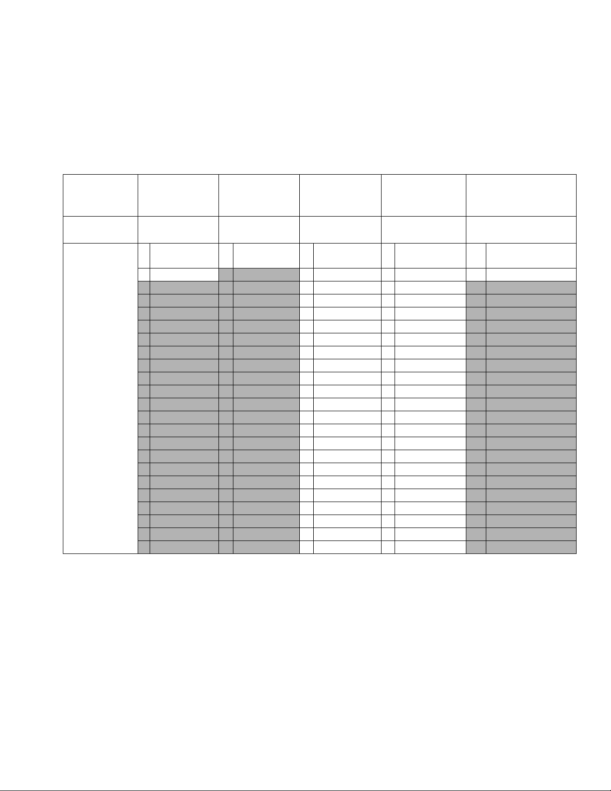
Models
Models
Use the following matrix to determine the 8-digit system part number.
NOTE: To order replacement parts, see the Parts section on page 25. The digits in the matrix do not correspond to
the Ref. Nos. in the Parts drawings and lists.
EFR
(First, Second
and Third Digits)
System
Designator
EFR
(Electric
Fixed-Ratio
Proportioner)
Digit 4 Digit 5 Digit 6 Digit 7 Digit 8
Voltage Options Control Options A Side Pump B Side Pump Material Options
2
4 480V
240V A ADM A 5 cc A 5 cc C
B 10 cc B 10 cc S Stainless Steel
C 15 cc C 15 cc
D 20 cc D 20 cc
E 25 cc E 25 cc
F 30 cc F 30 cc
G 35 cc G 35 cc
H 40 cc H 40 cc
I 45 cc I 45 cc
J 50 cc J 50 cc
K 60 cc K 60 cc
L 65 cc L 65 cc
M 70 cc M 70 cc
N 75 cc N 75 cc
O 80 cc O 80 cc
P 86 cc P 86 cc
Q 90 cc Q 90 cc
R 100 cc R 100 cc
S 105 cc S 105 cc
T 120 cc T 120 cc
U 140 cc U 140 cc
V 150 cc V 150 cc
W 160 cc W 160 cc
Carbon and Stain-
less Steel
3A6165A 3
Warnings
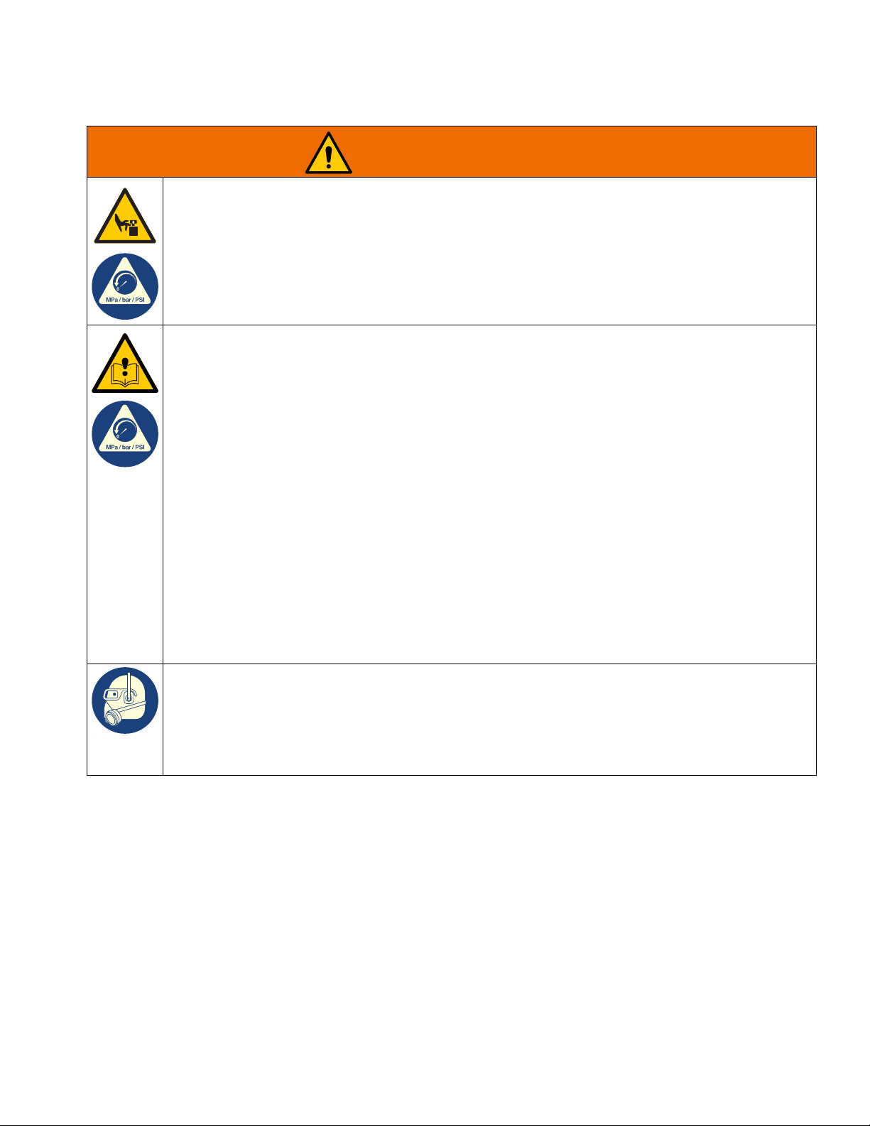
DANGER
Warnings
The following warnings are for the setup, use, grounding, maintenance, and repair of this equipment. The exclamation point symbol alerts you to a general warning and the hazard symbols refer to procedure-specific risks. When
these symbols appear in the body of this manual or on warning labels, refer back to these Warnings. Product-specific
hazard symbols and warnings not covered in this section may appear throughout the body of this manual where
applicable.
SEVERE ELECTRIC SHOCK HAZARD
This equipment can be powered by more than 240 V. Contact with this voltage will cause death or
serious injury.
• Turn off and disconnect power at main switch before disconnecting any cables and before servicing
equipment.
• This equipment must be grounded. Connect only to grounded power source.
• All electrical wiring must be done by a qualified electrician and comply with all local codes and
regulations.
4 3A6165A
Warnings
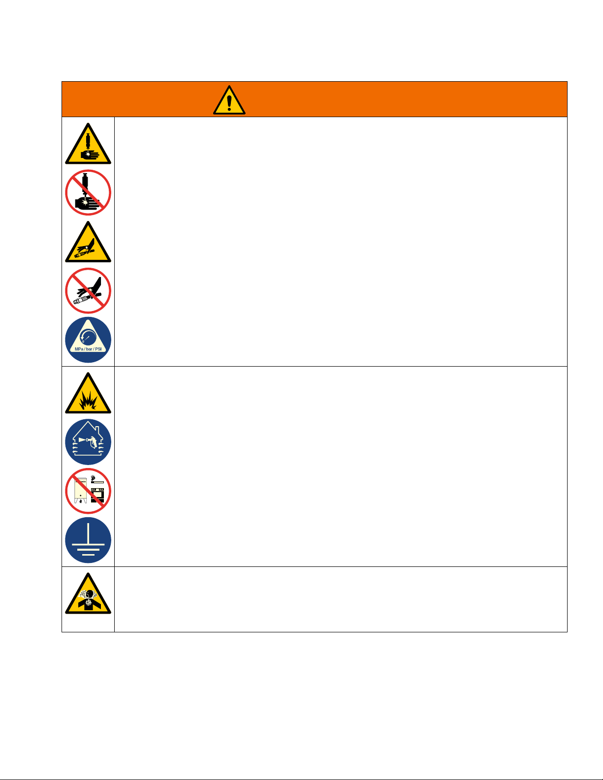
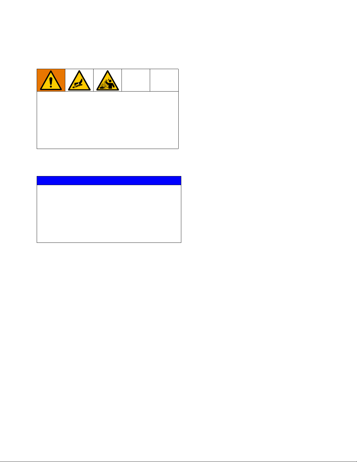
WARNING
SKIN INJECTION HAZARD
High-pressure fluid from dispensing device, hose leaks, or ruptured components will pierce skin. This
may look like just a cut, but it is a serious injury that can result in amputation. Get immediate surgical
treatment.
• Do not point dispensing device at anyone or at any part of the body.
• Do not put your hand over the fluid outlet.
• Do not stop or deflect leaks with your hand, body, glove, or rag.
• Follow the Pressure Relief Procedure when you stop dispensing and before cleaning, checking, or
servicing equipment.
• Tighten all fluid connections before operating the equipment.
• Check hoses and couplings daily. Replace worn or damaged parts immediately.
FIRE AND EXPLOSION HAZARD
Flammable fumes, such as solvent and paint fumes, in work area can ignite or explode. Paint or
solvent flowing through the equipment can cause static sparking. To help prevent fire and explosion:
• Use equipment only in well-ventilated area.
• Eliminate all ignition sources; such as pilot lights, cigarettes, portable electric lamps, and plastic drop
cloths (potential static sparking).
• Ground all equipment in the work area. See Grounding instructions.
• Never spray or flush solvent at high pressure.
• Keep work area free of debris, including solvent, rags and gasoline.
• Do not plug or unplug power cords, or turn power or light switches on or off when flammable fumes
are present.
• Use only grounded hoses.
• Stop operation immediately if static sparking occurs or you feel a shock. Do not use equipment until
you identify and correct the problem.
• Keep a working fire extinguisher in the work area.
TOXIC FLUID OR FUMES HAZARD
Toxic fluids or fumes can cause serious injury or death if splashed in the eyes or on skin, inhaled, or
swallowed.
• Read Safety Data Sheets (SDSs) to know the specific hazards of the fluids you are using.
• Store hazardous fluid in approved containers, and dispose of it according to applicable guidelines.
3A6165A 5
Warnings
WARNING
MOVING PARTS HAZARD
Moving parts can pinch, cut or amputate fingers and other body parts.
• Keep clear of moving parts.
• Do not operate equipment with protective guards or covers removed.
• Equipment can start without warning. Before checking, moving, or servicing equipment, follow the
Pressure Relief Procedure and disconnect all power sources.
EQUIPMENT MISUSE HAZARD
Misuse can cause death or serious injury.
• Do not operate the unit when fatigued or under the influence of drugs or alcohol.
• Do not exceed the maximum working pressure or temperature rating of the lowest rated system
component. See Technical Specifications in all equipment manuals.
• Use fluids and solvents that are compatible with equipment wetted parts. See Technical
Specifications in all equipment manuals. Read fluid and solvent manufacturer’s warnings. For
complete information about your material, request Safety Data Sheets (SDSs) from distributor or
retailer.
• Turn off all equipment and follow the Pressure Relief Procedure when equipment is not in use.
• Check equipment daily. Repair or replace worn or damaged parts immediately with genuine
manufacturer’s replacement parts only.
• Do not alter or modify equipment. Alterations or modifications may void agency approvals and create
safety hazards.
• Make sure all equipment is rated and approved for the environment in which you are using it.
• Use equipment only for its intended purpose. Call your distributor for information.
• Route hoses and cables away from traffic areas, sharp edges, moving parts, and hot surfaces.
• Do not kink or over bend hoses or use hoses to pull equipment.
• Keep children and animals away from work area.
• Comply with all applicable safety regulations.
PERSONAL PROTECTIVE EQUIPMENT
Wear appropriate protective equipment when in the work area to help prevent serious injury, including
eye injury, hearing loss, inhalation of toxic fumes, and burns. Protective equipment includes but is not
limited to:
• Protective eyewear, and hearing protection.
• Respirators, protective clothing, and gloves as recommended by the fluid and solvent manufacturer.
6 3A6165A
Warnings
Keep Components A (Red) and B (Blue) Separate
Cross-contamination can result in cured material in
fluid lines which could cause serious injury or damage
equipment. To prevent cross-contamination:
• Never interchange component A (red) and
component B (Blue) wetted parts.
• Never use solvent on one side if it has been
contaminated from the other side.
Changing Materials
NOTICE
Changing the material types used in your equipment
requires special attention to avoid equipment damage
and downtime.
• When changing materials, flush the equipment
multiple times to ensure it is thoroughly clean.
• Check with your material manufacturer for
chemical compatibility.
A (Red) and B (Blue) Components
NOTE: Material suppliers can vary in how they refer to
plural component materials.
For all machines:
• The A (Red) side is intended for hardeners and
catalysts.
• The B (Blue) side is intended for polyols, resins, and
bases. Regardless of the configuration of material
used, the high volume material must be in the B
(Blue) side.
3A6165A 7
Component Identification
F
G
H
C
M
A
S
B
D
K
J
N
P
R
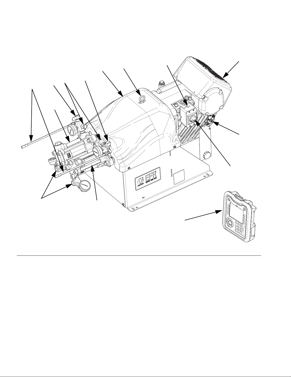
Component Identification
FIG. 1: Component Identification
Key:
AA Pump
BB Pump
C Power Disconnect Switch
D Advanced Display Module (ADM)
F Pump Yoke Shroud
G Electric Driver
H Incoming Power Connection
J Pump Inlets
K Pump Outlets
M Driver Communication and I/O Connectors
N Lift Ring
P Pressure Relief Drain Tubes
R A-Side Outlet Drain Valve
S B-Side Outlet Drain Valve
8 3A6165A
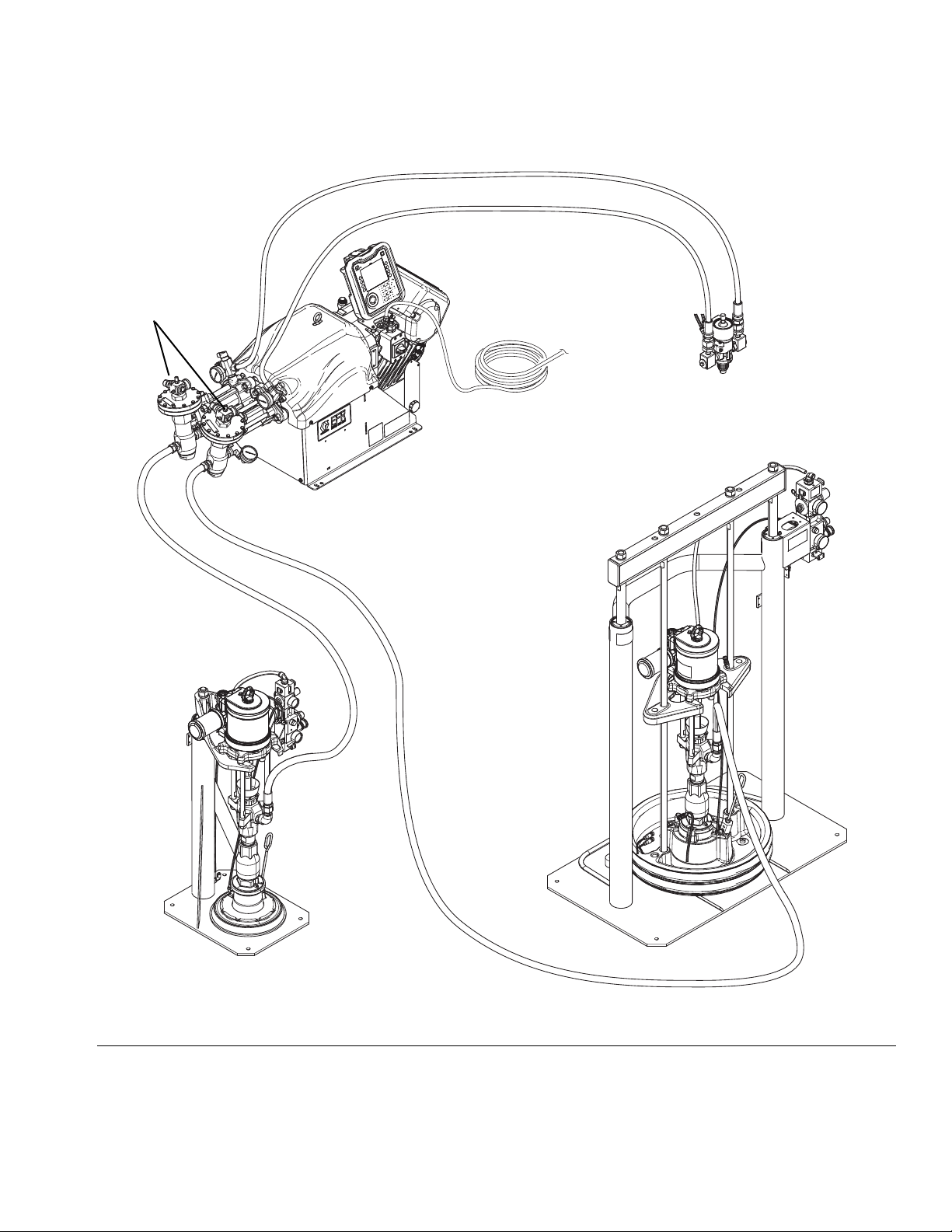
Typical Installation
WLD
Dispense Valve*
A Supply System*
B Supply System*
Power Cord with User
Supplied Dedicated
Circuit Protection
Inlet Regulators
EFR Proportioner
Component Identification
FIG. 2: Typical Installation
* Required accessories not supplied with the proportioner.
Optional accessories not supplied with the proportioner.
3A6165A 9
Component Identification
TI12362a1
AA
AB
AC
AE
AH
AG
AF
AD
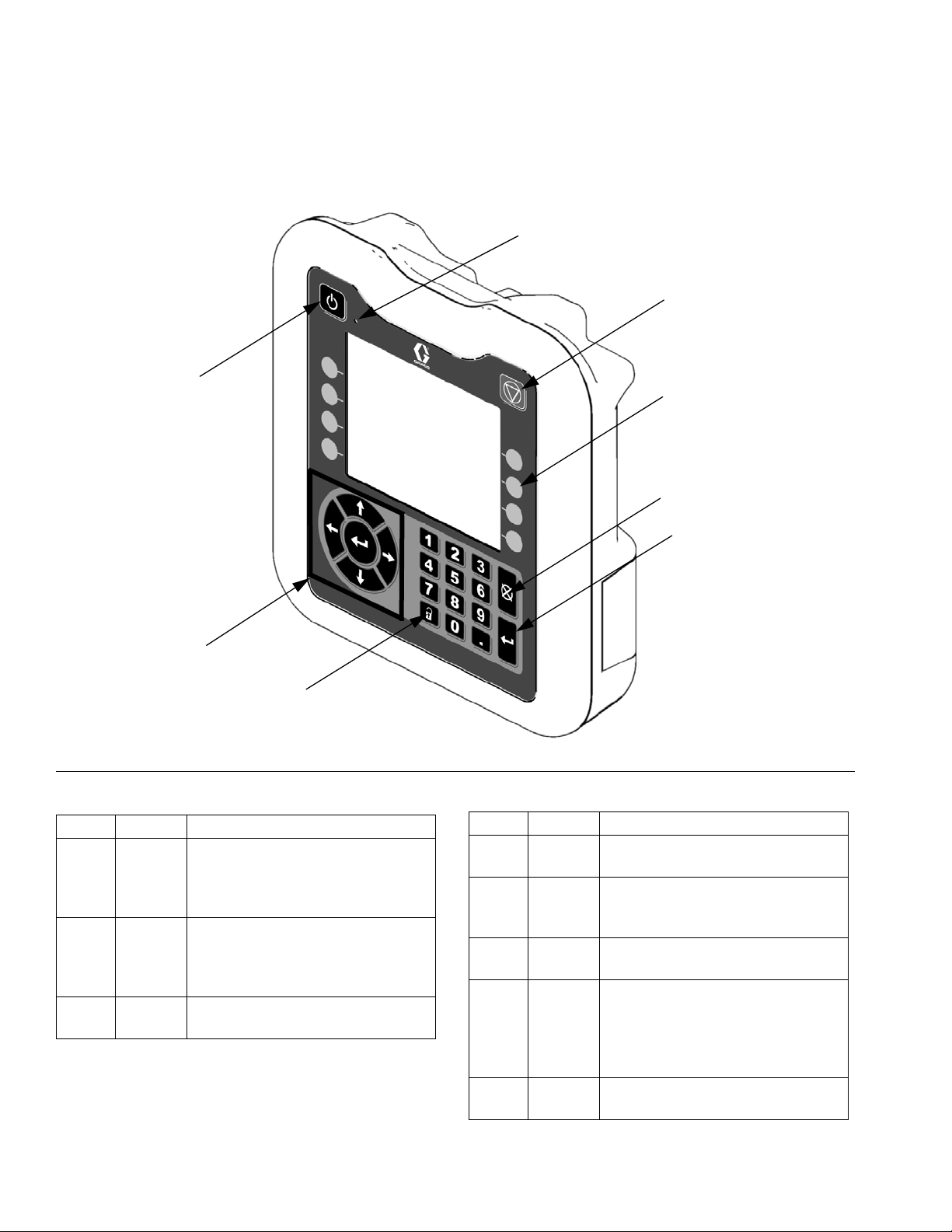
Advanced Display Module (ADM)
User Interface
FIG. 3: ADM Component Identification - Front
Buttons
Callout Button Function
AA System
enable/
disable
AB System
Status
Indicator
Light
AC Stop Stop all system processes. Is not a
Enables/disables system. When
system is disabled, temperature
control and dispense operation are
disabled.
Displays system status. See Sys-
tem Status Indicator (AB) Conditions on page 11 for details.
safety or emergency stop.
Callout Button Function
AD Soft
Defined by application using ADM.
Keys
AE Cancel Cancel a selection or number entry
while in the process of entering a
number or making a selection.
AF Enter Acknowledge changing a value or
making a selection.
AG Lock/SetupToggle between run and setup
screens. If setup screens are password protected, button toggles
between run and password entry
screen.
AH Naviga-
tion
Navigate within a screen or to a
new screen.
10 3A6165A
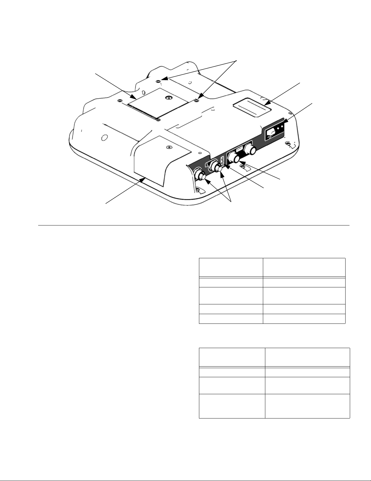
Component Identification
AR
AK
AJ
AL
AP
AN
AM
AS
ti12363a1
FIG. 4: ADM Component Identification - Rear
Key:
AJ Flat Panel Mount
AK Model Number
AL USB Module Interface
AM CAN Cable Connections
AN Module Status LEDs
AP Accessory Cable Connections
AR Token Access Cover
AS Battery Access Cover
System Status Indicator (AB) Conditions
Green Solid - Run Mode, System On
Green Flashing - Setup Mode, System On
Yellow Solid - Run Mode, System Off
Yellow Flashing - Setup Mode, System Off
ADM Module Status LEDs (AN) Conditions
Module Status LED
Signal Description
Green on System is powered up.
Yellow on Communication in prog-
ress.
Red solid ADM hardware failure.
Red flashing Uploading software.
USB Module Status LEDs (AL) Conditions
Module Status LED
Signal Description
Green flashing System is powered up.
Yellow on Downloading information to
Green/Yellow Flashing
USB
ADM is busy, USB cannot
transfer information when in
this mode
3A6165A 11
Installation
LQ
LQ
WLD
BB
BA
C
Installation
All electrical wiring must be done by a qualified electrician and comply with all local codes and regulations.
Grounding
The equipment must be grounded to reduce the risk
of static sparking and electric shock. Electric or static
sparking can cause fumes to ignite or explode.
Improper grounding can cause electric shock.
Grounding provides an escape wire for the electric
current.
EFR: grounded through the power cord (customer supplied).
Fluid supply containers: follow local code.
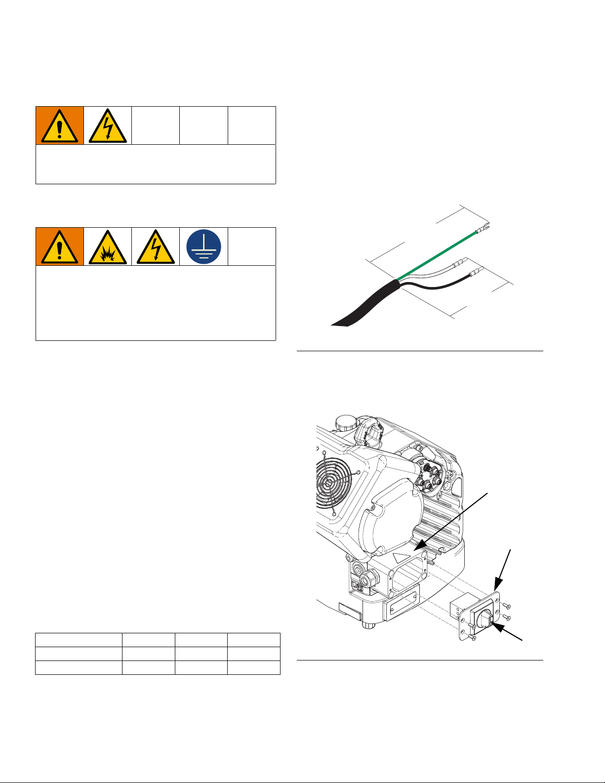
Connect Power
1. Cut power cord wires to the following lengths:
• Ground wire - 6.5 inches (16.5 cm)
• Power wires - 3.0 inches (7.6 cm)
• Add ferrules as necessary. See F
FIG. 5: Power Cord
2. Remove the four screws to separate the junction
box cover (BA) and disconnect switch (C) from the
junction box (BB) on the electrical driver.
IG. 5.
Object being dispensed: follow local code.
Solvent pails used when flushing: follow local code.
Use only conductive metal pails, placed on a grounded
surface. Do not place the pail on a nonconductive
surface, such as paper or cardboard, which interrupts
grounding continuity.
To maintain grounding continuity when flushing or
relieving pressure: hold metal part of the dispense
valve firmly to the side of a grounded metal pail, then
trigger the dispense valve.
Power Requirements
The system requires a dedicated circuit protected with a
circuit breaker.
Voltage Phase Hz Current
200-240 VAC 1 50/60 20 A
400-480 VAC 1 50/60 10 A
FIG. 6: Remove Junction Box Cover
12 3A6165A
Installation
WLE
/
/
/
7
7
7
BA
C
WLD
Cord Grip
WLD
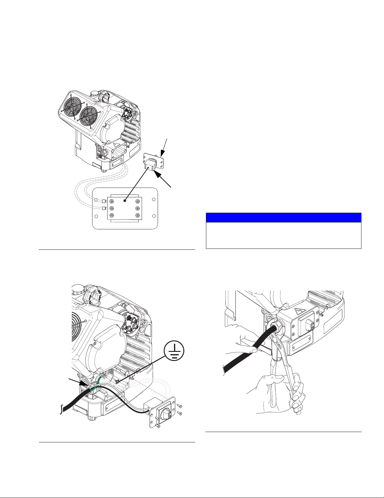
NOTE: Inside the junction box, power wires are
pre-installed to terminals 2T1 and 4T2 on the disconnect
block. Refer to F
IG. 7 for the terminal locations.
WLD
FIG. 7: Terminal Connections
4. Attach the ground wire to the ground terminal inside
the junction box as shown in F
5. Refer to F
IG. 7 and connect the wires from the
IG. 8.
power cord into terminals 1L1 and 2L2.
NOTE: For 480V systems, a step-down transformer is
factory-installed between the power disconnect switch
and the electric driver. See Wiring Diagrams on page
43.
NOTE: Do not attach the ground wire to the grounding
lug locknut on the outside of the electric driver. See
Grounding on page 12.
6. Place the power wires into the open area on either
side of the power disconnect switch (C) as space
permits.
7. Reinstall the junction box cover (BA) and disconnect
switch (C) using the four screws removed in step 2.
NOTICE
Make sure all wires are routed correctly before installation. If wires get pinched when the screws are tightened, damage will occur.
3. Insert the power cord through the cord grip and into
the junction box.
FIG. 8: Connect Power
8. Tighten the cord grip to securely hold the power
cord in the junction box.
FIG. 9: Tighten Cord Grip
3A6165A 13
Installation
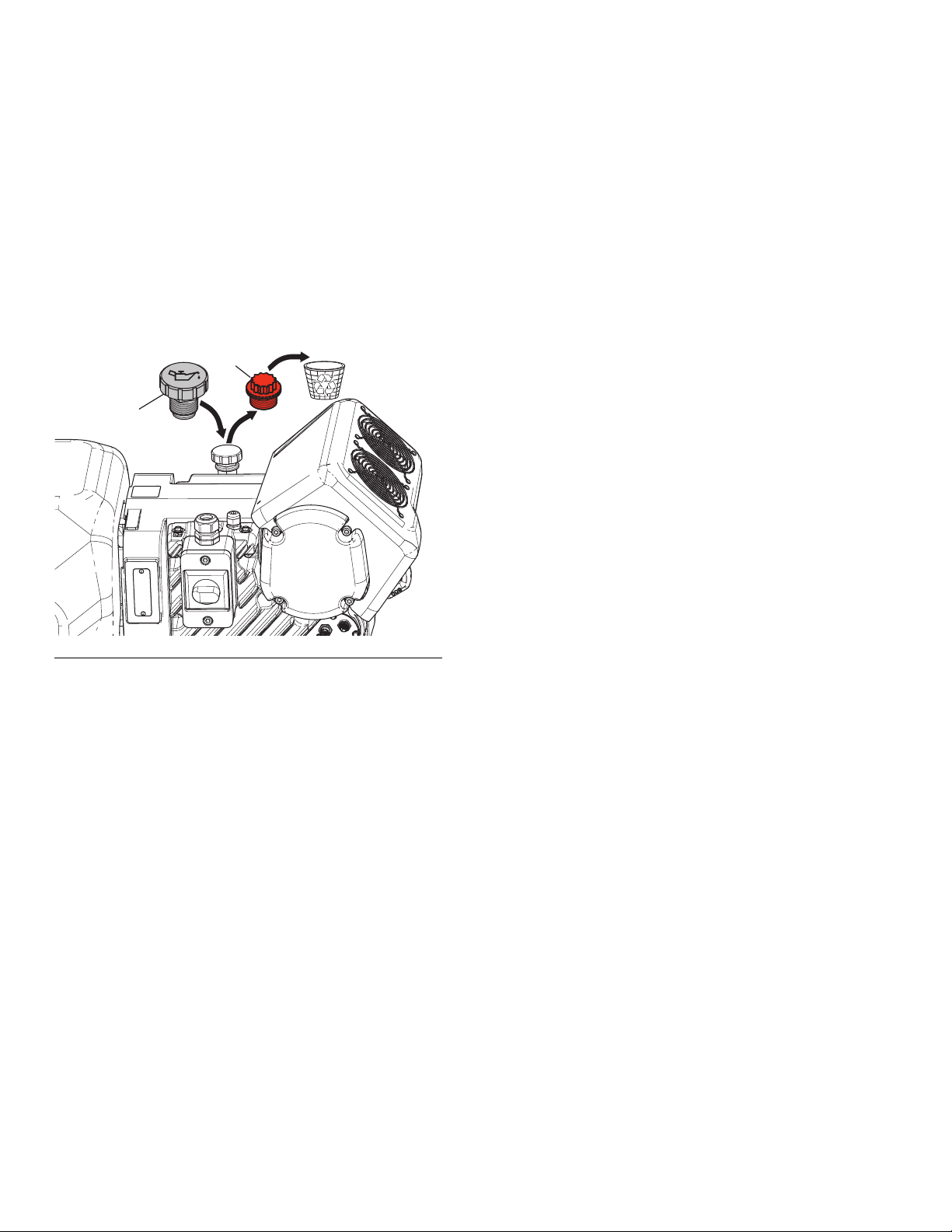
PX
PY
Install Vented Oil Cap Before Using Equipment
The driver gear-box is shipped from the factory pre-filled
with oil. The temporary unvented cap (PX) prevents oil
leaks during shipment. This temporary cap must be
replaced with the vented oil cap (PY), supplied with the
equipment, before use.
NOTE: Prior to use, check oil level. Oil level should be
half way up the sight glass.
FIG. 10: Unvented and Vented Oil Caps
14 3A6165A
 Loading...