

Page 1
Instructions-Parts
E-Flo® DC Motor
Electric drive for for low to medium volume paint circulation pumps.
For professional use only.
Important Safety Instructions
Read all warnings and instructions in this manual. Save these
instructions.
3A2526D
EN
See page 3
and appro
for model part numbers
vals information.
PROVEN QUALITY. LEADING TECHNOLOGY.
Page 2

Contents
Models............................................................... 3
Basic Models ............................................... 3
Basic Models w
Approvals....................................... 4
Advanced Mod
Advanced Mod
Approvals....................................... 6
Warnings ........................................................... 7
Installation.......................................................... 10
Fill With Oil Before Using Equipment............. 10
Power Supply Requirements......................... 10
Connect the Power Supply ........................... 11
Grounding ................................................... 12
Intrinsically Safe Installation Requirements
for Advanced Motors....................... 12
Operation
Maintenance ...................................................... 16
........................................................... 13
Startup ........................................................ 1
Shutdown
Pressure
Advanced
Basic Mo
tor Operation.................................. 14
ith Region-Specific
els ........................................ 5
els with Region-Specific
.................................................... 13
Relief Procedure............................ 13
Motor Operation ........................... 13
Preventive Ma
Change the Oil
Check Oil Leve
Bearing Pre-
Error Code Troubleshooting ................................ 17
Repair................................................................ 19
Replace Output Seal Cartridge ..................... 19
Parts.................................................................. 20
Basic Motor
Advanced Mo
Notes ................................................................ 24
Repair Kits, Related Manuals, and
Accessories .......................................... 25
Appendix A
3
Notes ................................................................ 31
Mounting Hole Pattern ........................................ 32
Technic
Graco Standard Warranty.................................... 34
24N637 ................................................ 26
al Data ................................................... 33
intenance Schedule ................ 16
............................................. 16
l ........................................... 16
Load......................................... 16
Assembly.................................. 20
tor Assembly ........................... 22
- System Control Drawing
2
3A2526D
Page 3
Models
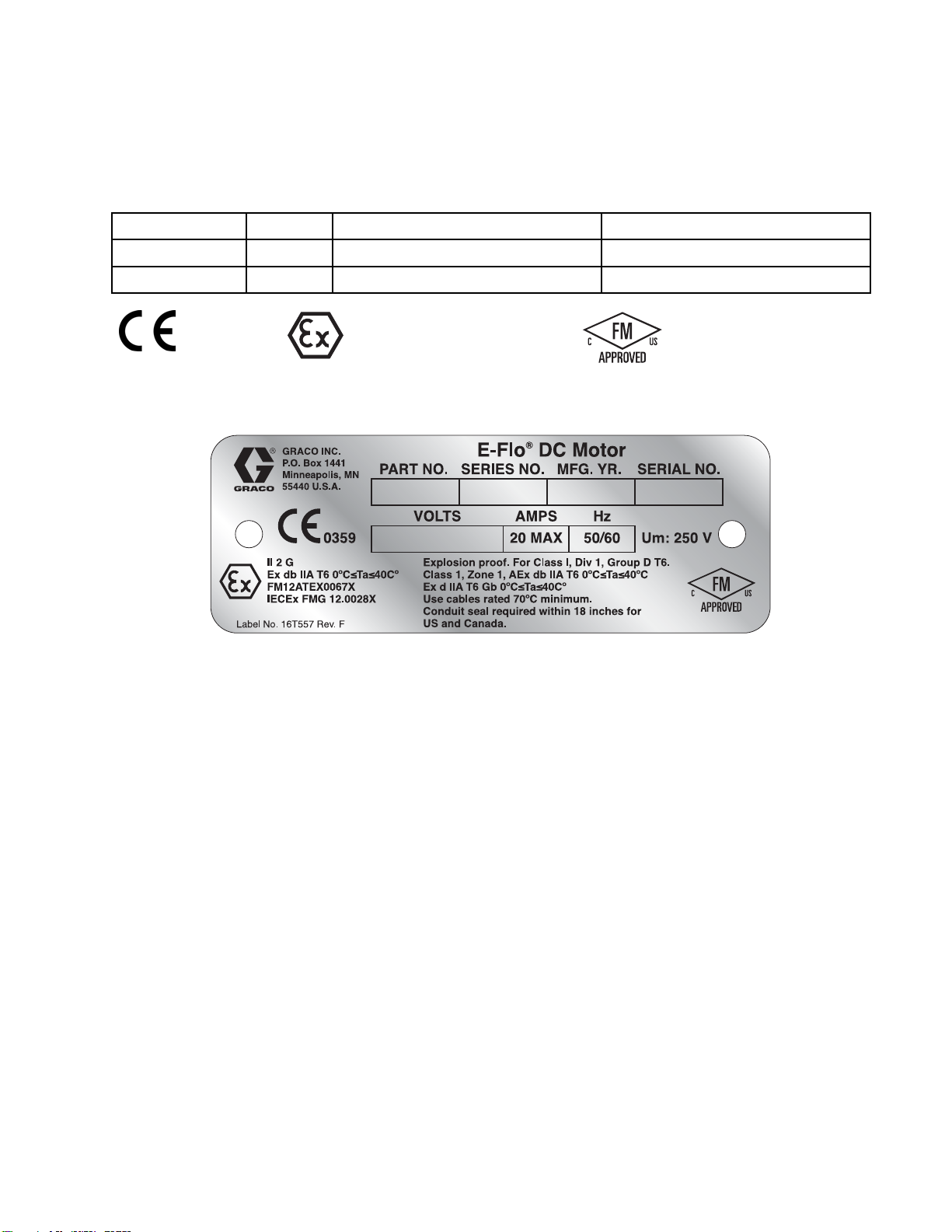
Basic Models
Models
Motor Part No.
EM0011 A 1
EM0021 A 2
0359
Figure 1
List of Standards
Basic Motor Identification Label
Series
Ex db IIA T6 0
FM12ATEX0
IECEx FMG 1
Horsepower
II 2 G
°C≤Ta≤40°C
067X
2.0028X
Maximum Forc
1400 (6227)
2800 (12455)
For Class I,
Class 1, Zo
Ex d IIA T6 G
ne 1, AEx db IIA T6 0°C≤Ta≤40°C
e, lbf (N)
Div. 1, Group D T6.
b 0°C≤Ta≤40°C
• IEC 60079–0: 2011 (Ed. 6)
• IEC 60079–1: 2007 w/Corr 1 (Ed 6)
• EN 60079–0: 2012
• EN 60079–1: 2007
• ANSI/ISA 60079–0: 2009
• ANSI/ISA 60079–1: 2009
• FM 3615:2006
ific Conditions of Use:
Spec
1. Consult the manufacturer if dimensional
information on the flameproof joint is necessary.
2. Consult the manufacturer for genuine
replacement fasteners. M8 x 30 socket-head
cap screws of Class 12.9 steel or better with a
minimum yield strength of 1100 MPa (160,000
psi) are acceptable alternatives.
• CSA C22.2 No. 0.4:2004 (R2009)
• CSA C22.2 No. 0.5:82 (R2008)
• CSA C22.2 No. 30:M86 (R2007)
• CAN/CSA-E60079–0:2011
• CAN/CSA-E60079–1:2011
• CAN/CSA C22.2 No. 1010.1:2004
3A2526D 3
Page 4
Models
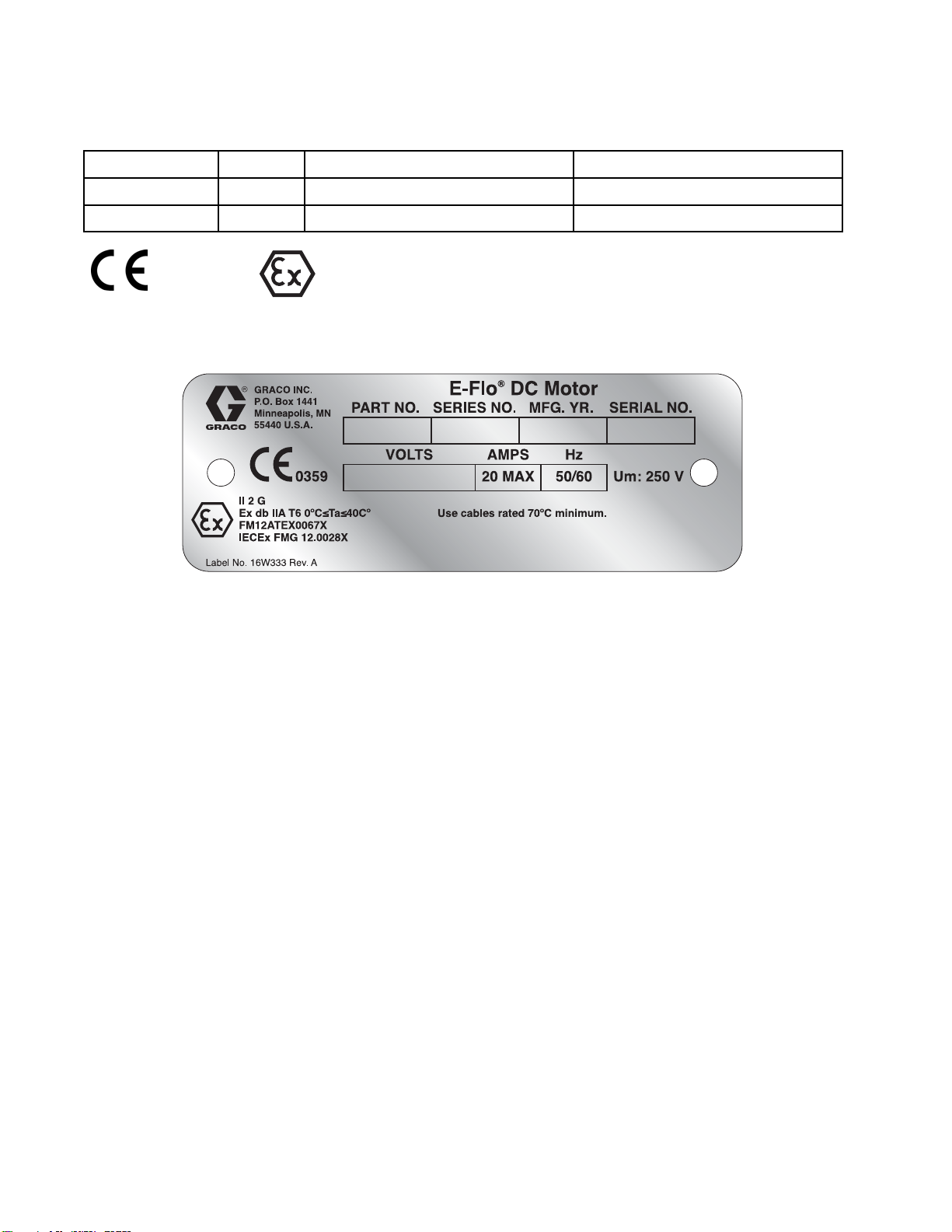
Basic Models w
Motor Part No.
EM0013 A 1
EM0023 A 2
0359
ith Region-Specific Approvals
Series
Ex db IIA T6 0°C≤Ta≤40°C
FM12ATEX0067X
IECEx FMG 12.0028X
Horsepower
II 2 G
Maximum Force, lbf (N)
1400 (6227)
2800 (12455)
Figure 2 Basic Motor with Region-Specific Approvals
Identification Label
List of S
• IEC 60079–0: 2011 (Ed. 6)
• IEC 60079–1: 2007 w/Corr 1 (Ed 6)
Specific Conditions of Use:
1. Consul
2. Consu
tandards
t the manufacturer if dimensional
mation on the flameproof joint is necessary.
infor
lt the manufacturer for genuine
cement fasteners. M8 x 30 socket-head
repla
rews of Class 12.9 steel or better with a
cap sc
um yield strength of 1100 MPa (160,000
minim
are acceptable alternatives.
psi)
• EN 60079–0: 2012
• EN 60079–1: 2007
4
3A2526D
Page 5
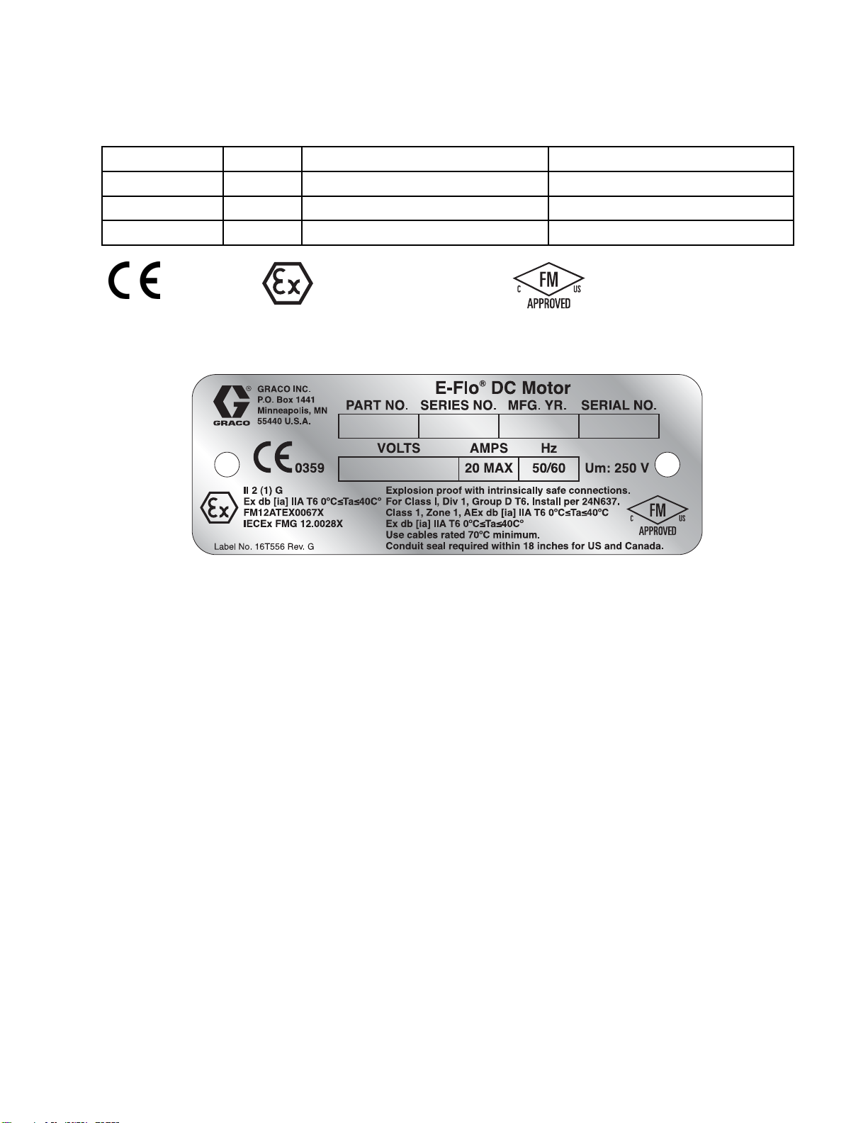
Advanced Models
Models
Motor Part No.
EM0012 A 1
EM0022 A 2
EM0025 A 2
0359
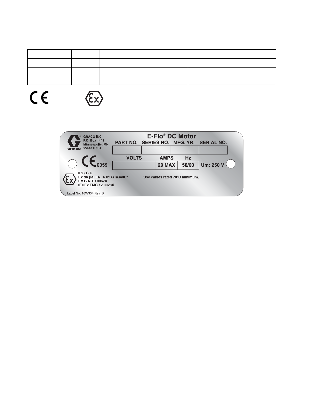
Figure 3 Advanced Motor Identification Label
Series
Ex db [ia] IIA T6 0°C≤Ta≤40°C
FM12ATEX0067X
IECEx FMG 12.0028X
Horsepower
II 2 (1) G
Maximum Force, lbf (N)
1400 (6227)
2800 (12455)
2800 (12455)
For Class I, Div. 1, Group D T6.
Class 1, Zone 1, AEx db [ia] IIA T6 0°C≤Ta≤40°C
Ex db [ia] IIA T6 0°C≤Ta≤40°C
List of Standards
• IEC 60079–0: 2011 (Ed. 6)
• IEC 60079–1: 2007 w/Corr 1 (Ed. 6)
• IEC 60079–11: 2011 (Ed. 6)
• EN 60079–0: 2012
• EN 60079–1: 2007
• EN 60079–11: 2012
• FM 3600:2011
• FM 3610:2010
• FM 3615:2006
• FM 3810:2005
• CSA C22.2 No. 0.4:2004 (R2009)
Specific Conditions of Use:
1. Consult the manufacturer if dimensional
information on the flameproof joint is necessary.
2. Consult the manufacturer for genuine
replacement fasteners. M8 x 30 socket-head
cap screws of Class 12.9 steel or better with a
minimum yield strength of 1100 MPa (160,000
psi) are acceptable alternatives.
• CSA C22.2 No. 0.5:82 (R2008)
• CSA C22.2 No. 30:M86 (R2007)
• CSA C22.2 No. 157–92 (R2006)
• CAN/CSA-E60079–0:2011
• CAN/CSA-E60079–1:2011
• CAN/CSA C22.2 No. 1010.1:2004
• CAN/CSA-E60079–11:2011
• ANSI/ISA 60079–0:2009
• ANSI/ISA 60079–1:2009
• ANSI/ISA 60079–11:2011
3A2526D 5
Page 6
Models
Advanced Mode
Motor Part No.
EM0014 A 1
EM0024 A 2
EM0026 A 2
0359
ls with Region-Specific Approvals
Series
Ex db [ia] IIA T6 0°C≤Ta≤40°C
FM12ATEX0067X
IECEx FMG 12.0028X
Horsepower
II 2 (1) G
Maximum Force, lbf (N)
1400 (6227)
2800 (12455)
2800 (12455)
Figure 4 Advanced Motor with Region-Specific
Approvals Identification Label
List of Standards
• IEC 600
•IEC600
•IEC60
Specific Conditions of Use:
1. Consult the manufacturer if dimensional
2. Consult the manufacturer for genuine
79–0: 2011 (Ed. 6)
79–1: 2007 w/Corr 1 (Ed. 6)
079–11: 2011 (Ed. 6)
information on the flameproof joint is necessary.
replacement fasteners. M8 x 30 socket-head
cap screws of Class 12.9 steel or better with a
minimum yield strength of 1100 MPa (160,000
psi) are acceptable alternatives.
• EN 6007
• EN 6007
• EN 600
9–0: 2012
9–1: 2007
79–11: 2012
6 3A2526D
Page 7
Warnings
Warnings
The following
exclamation p
risks. When th
Warnings. Pr
the body of th
warnings are for the setup, use, grounding, maintenance and repair of this equipment. The
oint symbol alerts you to a general warning and the hazard symbol refers to procedure-specific
ese symbols appear in the body of this manual or on warning labels, refer backtothese
oduct-specific hazard symbols and warnings not covered in this section may appear throughout
is manual where applicable.
WARNING
FIRE AND EX
Flammable fumes, such as solvent and paint fumes, in work area can ignite or explode. To help
prevent fire and explosion:
• Use equipment only in well ventilated area.
• Eliminate all ignition sources; such as pilot lights, cigarettes, portable electric lamps, and
plastic drop cloths (potential static arc).
•Keepwork
• Do not plug or unplug power cords, or turn power or light switches on or off when flammable
fumes are present.
• Ground all equipment in the work area. See Grounding instructions.
•Useonly
• Hold gun firmly to side of grounded pail when triggering into pail. Do not use pail liners unless
they are antistatic or conductive.
• Stop operation immediately if static sparking occurs or you feel a shock, Do not use
equipment until you identify and correct the problem.
• Keepaw
PLOSION HAZARD
area free of debris, including solvent, rags and gasoline.
grounded hoses.
orking fire extinguisher in the work area.
3A2526D
Static charge may build up on plastic parts during cleaning and could discharge and ignite
flammable vapors. To help prevent fire and explosion:
• Clean
•Dono
•Dono
SPECIAL CONDITIONS FOR SAFE USE
•Top
• The aluminum housing may spark upon impact or contact with moving parts, which may
• All flameproof joints are critical to the integrity of the motor as approved for hazardous
plastic parts only in well ventilated area.
t clean with a dry cloth.
t operate electrostatic guns in equipment work area.
revent the risk of electrostatic sparking, the equipment’s non-metallic parts should be
aned only with a damp cloth.
cle
cause fire or explosion. Take precautions to avoid such impact or contact.
locations and are not repairable if damaged. Damaged parts must be replacedonlywith
genuine Graco parts with no substitutions.
7
Page 8
Warnings
WARNING
ELECTRIC SHOCK HAZARD
This equipment must be grounded. Improper grounding, setup, or usage of the system can
cause electric shock.
• Turn off and d
servicing or
• Connect only to grounded power source.
• All electrical wiring must be done by a qualified electrician and comply with all local codes
and regulations.
INTRINSIC
Intrinsic
equipment
Follow loc
• Be sure your installation complies with national, state, and local codes for the installation of
• Equipment that comes in contact with the equipment’s intrinsically safe terminals must
• Do not install any equipment approved only for a non-hazardous location in a hazardous
• Ground the motor. Use a 12 gauge minimum ground wire, connected to a true earth ground.
ally safe equipment that is installed improperly or connected to non-intrinsically safe
electrical apparatus in a Class I, Group D, Division 1 Hazardous Location, including all of the
local safety fire codes, NFPA 33, NEC 500 and 516, and OSHA 1910.107.
meet the entity parameter requirements specified in Control Drawing 24N637. See
Intrinsically Safe Installation Requirements for Advanced Motors, page 12. This includes
safety barriers, DC voltage meters, ohmmeters, cables, and connections. Remove the unit
from the hazardous area when troubleshooting.
area, as defined in Article 500 of the National Electrical Code (USA) or your local electrical
code. See the ID label for the intrinsic safety rating for your equipment.
See Grounding, page 12.
isconnect power at main switch before disconnecting any cables and before
installing equipment.
SAFETY
will create a hazardous condition and can cause fire, explosion, or electricshock.
al regulations and the following safety requirements.
• Do not operate the motor with any cover removed.
• Do not substitute system components, as this may impair intrinsic safety.
BURN HAZARD
Equipment surfaces and fluid that’s heated can become very hot during operation. To avoid
severe burns:
•Dono
MOVING PARTS HAZARD
Moving parts can pinch, cut or amputate fingers and other body parts.
•Kee
• Do not operate equipment with protective guards or covers removed.
• Pressurized equipment can start without warning. Before checking, moving, or servicing
t touch hot fluid or equipment.
p clear of moving parts.
equipment, follow the Pressure Relief Procedure and disconnect all power sources.
8 3A2526D
Page 9
Warnings
WARNING
PRESSURIZED EQUIPMENT HAZARD
Fluid from the equipment, leaks, or ruptured components can splash in the eyes or on skin
and cause serious injury.
• Follow the Pr
cleaning, ch
• Tighten all fluid connections before operating the equipment.
• Check hoses, tubes, and couplings daily. Replace worn or damaged parts immediately.
TOXIC FLUID
Toxic fluid
inhaled, o
• Read MSDSs to know the specific hazards of the fluids you are using.
• Store haza
guideline
PERSONAL PROTECTIVE EQUIPMENT
Wear appropriate protective equipment when in the work area to help prevent serious injury,
including eye injury, hearing loss, inhalation of toxic fumes, and burns. This equipment includes
but is not limited to:
•Protect
• Respirators, protective clothing, and gloves as recommended by the fluid and solvent
manufacturer.
EQUIPMENT MISUSE HAZARD
Misuse can cause death or serious injury.
• Do not operate the unit when fatigued or under the influence of drugs or alcohol.
• Do not exceed the maximum working pressure or temperature rating of the lowest rated
system component. See Technical Data in all equipment manuals.
•Useflu
l equipment manuals. Read fluid and solvent manufacturer’s warnings. For complete
in al
rmation about your material, request MSDS from distributor or retailer.
info
• Do not leave the work area while equipment is energized or under pressure.
• Turn off all equipment and follow the Pressure Relief Procedure when equipment is not in use.
• Chec
• Do not alter or modify equipment. Alterations or modifications may void agency approvals
• Make sure all equipment is rated and approved for the environment in which youareusingit.
•Use
• Route hoses and cables away from traffic areas, sharp edges, moving parts, and hot surfaces.
• Do not kink or over bend hoses or use hoses to pull equipment.
•Ke
• Comply with all applicable safety regulations.
k equipment daily. Repair or replace worn or damaged parts immediately with genuine
ufacturer’s replacement parts only.
man
and create safety hazards.
equipment only for its intended purpose. Call your distributor for information.
ep children and animals away from work area.
essure Relief Procedure when you stop spraying/dispensing and before
ecking, or servicing equipment.
OR FUMES
s or fumes can cause serious injury or death if splashed in the eyes or on skin,
r swallowed.
rdous fluid in approved containers, and dispose of it according to applicable
s.
ive eyewear, and hearing protection.
ids and solvents that are compatible with equipment wetted parts. See Technical Data
3A2526D 9
Page 10
Installation
Installation
Installation of this equipment involves potentially
hazardous procedures. Only trained and qualified
personnel who have read and who understand
the information in this manual should install this
equipment.
NOTE: To install an advanced motor, also see
Intrinsically Safe Installation Requirements for
Advanced Motors, page 12.
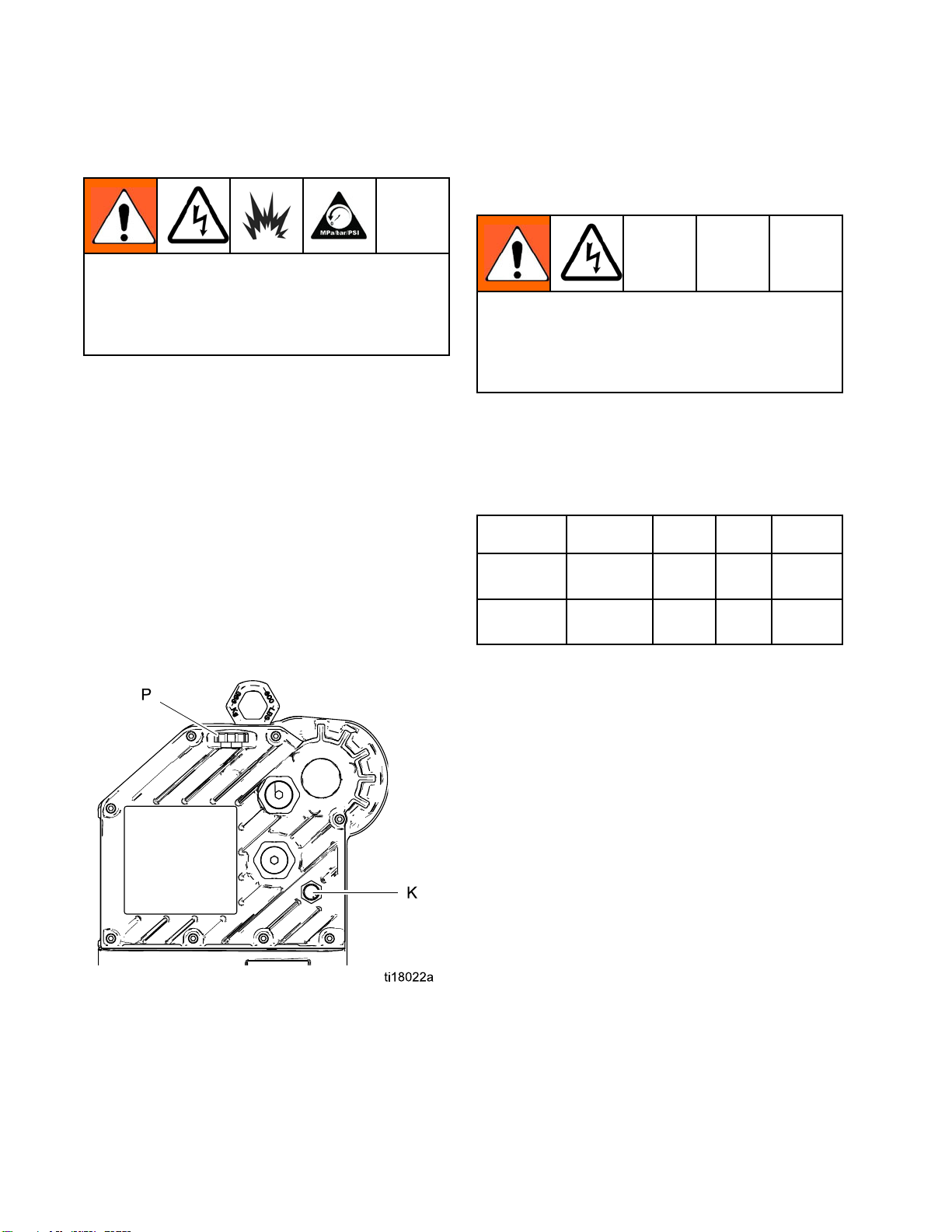
Fill With Oil Before Using Equipment
See Fig. 5. Before using the equipment, open the fill
cap (P) and add Graco Part No. 16W645 ISO 220
silicone-free synthetic gear oil. Check the oil level in
the sight glass (K). Fill until the oil level is near the
halfway point of the sight glass. The oil capacity is
approximately 1.5 quarts (1.4 liters). Do not overfill.
NOTE: Two 1 quart (0.95 liter) bottles of oil are
supplied with the equipment.
Power Supply Requirements
Improper wiring may cause electric shock or other
serious injury if work is not performed properly.
Have a qualified electrician perform any electrical
work. Be sure your installation complies with all
National, State and Local safety and fire codes.
See Table 1 for power supply requirements. The
system requires a dedicated circuit protected with a
circuit breaker.
Table 1 .
Model* Voltage Phase Hz Current
EM001x 100–250
EM002x 200–250
* The last digit of the Model No. varies. See the
Models tables on pages 3–6.
Power Supply Specifications
1 50/60 20 A
Vac
1 50/60 20 A
Vac
Hazardous Area Cabling and Conduit Requirements
Explosion Proof
All electrical wiring in the hazardous area must be
encased in Class I, Division I, Group D approved
explosion-proof conduit. Follow all National, State,
and Local electric codes.
A conduit seal (D) is required within 18 in. (457 mm)
of the motor for the US and Canada. See Fig. 7.
All cables must be rated at 70°C.
Figure 5 Sightglass and Oil Fill Cap
Flame Proof (ATEX)
Use appropriate conduit, connectors, and cable
glands rated for ATEX II 2 G. Follow all National,
State, and Local electric codes.
All cable glands and cables must be rated at 70°C.
10 3A2526D
Page 11
Installation
Connect the Po
Improper wiring may cause electric shock or other
serious injury if work is not performed properly.
Have a qualified electrician perform any electrical
work. Be sure your installation complies with all
National, State and Local safety and fire codes.
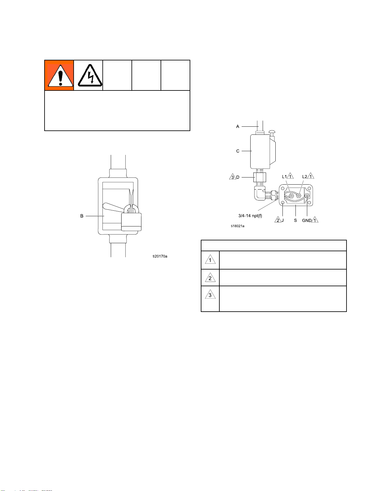
1. Ensure that the fused safety switch (B, Fig. 6) is
shut off and locked out.
wer Supply
4. Bring the powe
compartment t
Connect the wi
Torque the te
maximum. Do n
5. Close the ele
cover screw
rminal nuts to 25 in-lb (2.8 N•m)
ctrical compartment. Torque the
s (J) to 15 ft-lb (20.3 N•m).
r wires into the electrical
hrough the 3/4–14 npt(f) inlet port.
res to the terminals, as shown.
ot over-torque.
Figure 6 Locked Out Fused Safety Switch
2. See Fig. 7. Install a start/stop control (C) in the
electrical supply line (A), within easy reach of
the equipment. The start/stop control must be
approved for use in hazardous locations.
3. Open the electrical compartment (S) on the
motor.
Figure 7 Connect the Power Wires
Notes for Fig. 7
Tighten all terminal nuts to 25 in-lb (2.8 N•m)
maximum. Do not over-torque.
en cover screws to 15 ft-lb (20.3 N•m).
Tight
A conduit seal (D) is required within 18
in. (457 mm) of the motor for the US and
Canada.
3A2526D
11
Page 12

Installation
Grounding
This equipment must be grounded to reduce the
risk of static sparking and electric shock. Electric
or static sparking can cause fumes to ignite or
explode. Improper grounding can cause electric
shock. Grounding provides an escape wire for the
electric current.
NOTE: For advanced motors EM0012 and
EM0022, all motors must be bonded to the
same high integrity equipotential system. See
Intrinsically Safe Installation Requirements for
Advanced Motors, page 12.
See Fig. 8. Loosen the ground screw and attach a
ground wire (Y). Tighten the ground screw securely.
Connect the other end of the ground wire to a true
earth ground.
Intrinsicall
y Safe Installation
Requirements for Advanced Motors
Do not substitute or modify system components
as this may impair intrinsic safety. For installation,
maintenance, or operation instructions, read
instruction manuals. Do not install equipment
approved only for non-hazardous location in a
hazardous location. See the identification label for
the intrinsic safety rating for your model.
See Appendix A - System Control Drawing 24N637,
page 26, for installation requirements and entity
parameters. Follow all installation instructions in your
system manual.
Figure 8 Ground Wire
2
1
3A2526D
Page 13

Operation
Operation
Startup
1. See Fig. 6 on page 11. Unlock the fused safety
switch (B) and turn it on.
2. See Fig. 7 on page 11. Press the start
pushbutton (C).
3. See Fig. 9. Check that the power indicator (L)
is lit (steady on).
4. See Advanced Motor Operation, page 13 or
Basic Motor Operation, page 14 for further
instructions.
Figure 9 Power Indicator
Pressure Reli
This equipment stays pressurized until pressure is
manually relieved. To help prevent serious injury
from splashing fluid and moving parts, follow the
Pressure Relief Procedure when you stop spraying
and before cleaning, checking, or servicing the
equipment.
1. Disengage the start/stop control (C). See Fig. 7.
2. Shut off and lock out the fused safety switch (B).
See Fig. 6.
3. Relieve all fluid pressure as explained in your
separate E-Flo DC pump manual.
ef Procedure
Advanced Motor Operation
The Advanced E-Flo DC motors require installation of
the 24P822 Control Module Accessory Kit to provide
the interface for users to enter selections and view
information related to setup and operation. See Fig.
10. See the Control Module Accessory Kit manual for
installation and operation information.
NOTICE
To prevent damage to the softkey buttons, do not
Shutdown
Follow the Pressure Relief Procedure, page 13.
3A2526D 13
press the buttons with sharp objects such as pens,
plastic cards, or fingernails.
gure 10 Control Module Accessory
Fi
Page 14

Operation
Basic Motor Op
The basic motor has three operating modes:
• Pressure Mode
• Pressure Mode with Integrated Runaway
Protection
• Flow Mode
NOTE: Before changing from one mode to another,
turn the Control Knob (N) fully counterclockwise to 0.
eration
Pressure Mode
When in pressure mode, the motor will adjust the
speedtomaintainaconstantfluidpressure.
1. See Fig. 11. Turn the Control Knob (N) fully
counterclockwise to 0.
2. Pull the Mode Select switch (M) out to set. Turn
the switch to Pressure
to lock.
. Push the switch in
Pressure Mode with Integrated Runaway Protection
In pressure mode with integrated runaway protection,
the motor will adjust the speed to maintain a constant
fluid pressure, but will shut down if it exceeds a
user-set speed.
1. See Fig. 12.
counterclo
2. Pull the Mo
the Runaway
desired shutdown speed in cycles per minute (5,
10, 15, 20, or 25). Push the switch in to lock.
3. Pull the Control Knob (N) out to set. Turn the
knob clockwise to increase the pressure, or
counterclockwise to decrease the pressure.
Push the knob in to lock.
NOTE: The motor will shut down if the selected
speed is exceeded for 5 cycles. To reset, turn the
Control Knob (N) fully counterclockwise to 0, then
turn to the desired pressure.
Turn the Control Knob (N) fully
ckwise to 0.
de Select switch (M) out to set. In
range, turn the switch to the
3. Pull the Control Knob (N) out to set. Turn the
knob clockwise to increase the pressure, or
counterclockwise to decrease the pressure.
Push the knob in to lock.
Figure 11 Pressure Mode
Figure 12 Pressure Mode with Integrated Runaway
Protection
4
1
3A2526D
Page 15

Flow Mode
When in flow mode, the motor will maintain a
constant speed regardless of the fluid pressure, up
to the pump’s maximum working pressure. See
Technical Data, page 33.
Operation
1. See Fig. 13. T
countercloc
2. Pull the Mode
theswitchtoFlow
lock.
3. The amount of flow is determined by the cycle
rate set with the Control Knob (N). The knob’s
scale (0–10) corresponds to a cycle adjustment
range of 0-30 cycles per minute. Turn the Control
Knob(N)clockwisetoincreasethecyclerate
(flow), or counterclockwise to decrease the cycle
rate (flow).
urn the Control Knob (N) fully
kwiseto0.
Select switch (M) out to set. Turn
. Push the switch in to
Figure 13 Flow Mode
3A2526D 15
Page 16

Maintenance
Maintenance
Preventive Maintenance Schedule
The operating conditions of your particular system
determine how often maintenance is required.
Establish a preventive maintenance schedule by
recording when and what kind of maintenance is
needed, and then determine a regular schedule for
checking your system.
Change the Oil
NOTE: Change the oil after a break-in period of
200,000–300,000 cycles. After the break-in period,
change the oil once a year. Order two Part No.
16W645 ISO 220 silicone-free synthetic gear oil.
1. See Fig. 14. Place a minimum 2 quart (1.9 liter)
container under the oil drain port. Remove the
oil drain plug (25). Allow all oil to drain from the
motor.
2. Reinstall the oil drain plug (25). Torque to 25–30
ft-lb (34–40 N•m).
3. See Fig. 15. Open the fill cap (P) and add Graco
Part No. 16W645 ISO 220 silicone-free synthetic
gear oil. Check the oil level in the sight glass (K).
Fill until the oil level is near the halfway point of
the sight glass. The oil capacity is approximately
1.5 quarts (1.4 liters). Do not overfill.
4. Reinstall the fill cap.
Check Oil Level
See Fig. 15. Check the oil level in the sight glass (K).
The oil level should be near the halfway point of the
sight glass when the unit is not running. If low, open
the fill cap (P) and add Graco Part No. 16W645 ISO
220 silicone-free synthetic gear oil as required. The
oil capacity is approximately 1.5 quarts (1.4 liters).
Do not overfill.
Figure 15 Sightglass and Oil Fill Cap
Bearing Pre-Load
See Fig. 15. The bearing pre-loads (R) are factory
set and are not user adjustable. Do not adjust the
bearing pre-loads.
Figure 14 Oil Drain Plug
16 3A2526D
Page 17

Error Code Troubleshooting
Error Code Troub
leshooting
Error codes ca
•Alarm
down the pump
• Deviation
may continu
system’s ab
•Advisory:
operate.
NOTE: On Advanced motors, flow (K codes) and
pressure (P codes) can be designated as alarms
or deviations. See Setup Screen 4 in the Control
Module Manual.
Applicable
Motor
Advanced 1–2
Advanced None
Basic and
Advanced
n take three forms:
s you to the alarm cause and shuts
:alert
.
alerts you to the problem, but pump
:
e to run past the set limits until the
solute limits are reached.
information only. Pump will continue to
Blink Code Display Code
K1D?
K2D?
1
K4D?
NOTE: In the er
thecodeisass
NOTE: In the error codes listed below, a “?” in the
code is a placeholder for the unit number where the
event occurred.
NOTE: The blink code is displayed using the power
indicator on the motor. The blink code given below
indicates the sequence. For example, blink code 1–2
indicates 1 blink, then 2 blinks; the sequence then
repeats.
NOTE: Abli
an indicator of which pump is active (
has been pushed, see Run Screen 1 in the Control
Module Manual).
Alarm or
Deviation
Alarm Flow is below minimum limit.
Deviation Flow is below minimum limit.
Alarm Flow exceeds maximum target; also
ror codes listed below, an “X” means
ociated with the display only.
nk code of 9 is not an error code, but
Description
indicates pump runaway condition exists.
softkey
Advanced None
Advanced 1–3
Advanced None
Advanced 1–4
Advanced None
Basic and
Advanced
Basic and
Advanced
Advanced 2–3
Advanced None
2
3
K3D?
P1I?
P2I?
P4I?
P3I?
V1I?
V4I?
CAD?
CAC?
Deviation Flow exceeds maximum target; also
indicates pump runaway condition exists.
Alarm Pressure is below minimum limit.
Deviation Pressure is below minimum limit.
Alarm Pressure exceeds maximum target.
Deviation Pressure exceeds maximum target.
Alarm Brown out; voltage supplied to motor is too
low.
Alarm Voltage supplied to motor is too high.
Alarm
Alarm
Unit detects a loss of CAN communication.
This alarm is only logged. No flashing
alarm appears on the display, but the blink
code does occur.
Display detects a loss of CAN
communication. Flashing alarm
appears on the display, and the blink code
occurs.
CONTINUED ON THE NEXT PAGE.
3A2526D
17
Page 18

Error Code Troub
leshooting
Applicable
Motor
Advanced 2–4
Basic and
Advanced
Advanced 1–5
Basic and
Advanced
Advanced None P5DX Deviation More than one pump is assigned to a
Advanced None
Advanced 1–6
Advanced None
Blink Code Display Code
CAG?
4
5
WXD?
WSD?
T3D?
P6CA or
P6CB
P6D?
MND?
Alarm or
Deviation
Alarm
Alarm
Alarm
Deviation
Deviatio
Alarm For units with closed loop pressure control:
Advisory Maintenance counter is enabled and
Display detects a loss of modbus
communication when control access is set
to modbus.
An internal circuit board hardware failure
is detected.
Invalid low
operated be
Over temperature.
transducer. The assignment for that
transducer is automatically cleared under
this condition. User must reassign.
n
For units
: Transducer (A or B) is enabled
control
but not d
Transducer is enabled but not detected.
countdown reached zero (0).
Description
er size; occurs if the unit is
fore setting up the lower size.
without closed loop pressure
etected.
Basic 6 None Alarm
Basic and
Advanced
Basic and
Advanced
ic and
Bas
anced
Adv
Basic and
Advanced
Basic and
Advanced
sic and
Ba
dvanced
A
2–6
3–5
3–4
3–6
4–5
9NoneNo
V1M?
T2D?
WNC?
CCN?
C?
WM
The Mode Select knob is set between
ure
Press
desired mode.
to the
Alarm
Alarm Internal thermistor disconnected.
rm
Ala
Alarm
Alarm
ne
AC power is lost.
Software versions do not match.
Circuit board communication failure.
ternal software error.
In
A blink code of 9 is not an error code, but
an indicator of which pump is active (see
NOTE above).
and Flow . Set knob
18 3A2526D
Page 19

Repair
Repair
Replace Output Seal Cartridge
1. Stop the pump at the bottom of its stroke. Shut
off and lock out power to the motor.
2. Follow the Pressure Relief Procedure, page 13.
3. Disconnect the lower from the motor, as
explained in your separate E-Flo DC pump
manual.
4. Drain the oil from the motor. See
Change the Oil, page 16.
5. Reinstall the oil drain plug. Torque to 25–30 ft-lb
(34–40 N•m).
6. Unscrew the output cartridge (19) from the motor.
See Parts, page 20.
7. Install the new output cartridge. Torque to 70–80
ft-lb (95–108 N•m).
8. Fill with oil. See Change the Oil, page 16.
9. Reconnect the lower to the motor.
10. Turn on power and resume operation.
3A2526D 19
Page 20

Parts
Parts
Basic Motor Assembly
EM0011, Seri
EM0013, Seri
EM0021, Seri
EM0023, Ser
es A, 1 Horsepower Motor
es A, 1 Horsepower Motor, with Region-Specific Approvals
es A, 2 Horsepower Motor
ies A, 2 Horsepower Motor, with Region-Specific Approvals
20 3A2526D
Page 21

EM0011, Series A, 1 Horsepower Motor
Parts
EM0013, Serie
EM0021, Series A, 2 Horsepower Motor
EM0023, Series A, 2 Horsepower Motor, with Region-Specific Approvals
Part Description
Ref
———
1
3 116343
9 15F931
13 15H525
14 24E315
19 24K341
———
24
25 15H432
———
27
33▲ 16M130 LABEL,
s A, 1 Horsepower Motor, with Region-Specific Approvals
Part Description
Ref
16W360 LABEL, warning
34▲ 196548 LABEL, warn
36 16U113 KIT, knob; k
38 16W645
———
43
HOUSING, mot
SCREW, groun
x0.8
RING, lift
CAP, oil fill
SIGHT GLASS
CARTRIDGE, output
seal
SCREW, cap, socket
head; M8 x 1.25; 30
mm
PLUG, oi
COVER, e
compart
(EM001
EM0021
ment
warning
1and
)
or
d; M5
ldrain
lectrical
Qty
1
3
1
1
1
1
4
1
1
1
(EM0013 and
EM0023)
ing
it
includes re
parts for on
OIL, gear, synthetic;
ISO 220 silicone-free;
1 quart (0.95 liter);
not shown
WASHER, l
spring;
placement
eknob
ock,
no. 8
Qty
1
1
2
2
4
acement Danger and Warning labels, tags,
▲Repl
rds are available at no cost.
and ca
marked — — — are not available separately.
Items
3A2526D
21
Page 22

Parts
Advanced Motor Assembly
EM0012, Serie
EM0014, Serie
EM0022, Serie
EM0024, Serie
EM0025, Seri
EM0026, Seri
s A, 1 Horsepower Motor
s A, 1 Horsepower Motor, with Region-Specific Approvals
s A, 2 Horsepower Motor
s A, 2 Horsepower Motor, with Region-Specific Approvals
es A, 2 Horsepower Motor
es A, 2 Horsepower Motor, with Region-Specific Approvals
2
2
3A2526D
Page 23

EM0012, Series A, 1 Horsepower Motor
Parts
EM0014, Serie
EM0022, Series A, 2 Horsepower Motor
EM0024, Series A, 2 Horsepower Motor, with Region-Specific Approvals
EM0025, Seri
EM0026, Series A, 2 Horsepower Motor, with Region-Specific Approvals
Part Description
Ref
———
1
3 116343
9 15F931
13 15H525
14 24E315
19 24K341
———
24
25 15H432
———
27
s A, 1 Horsepower Motor, with Region-Specific Approvals
es A, 2 Horsepower Motor
Part Description
Ref
33▲ 16M130 LABEL, warning
16W360 LABEL, warning
34▲ 196548 LABEL, war
38 16W645
———
43
HOUSING, motor
SCREW, ground; M5
x0.8
RING, lift
CAP, oil fill
SIGHT GLASS
CARTRIDGE, output
seal
SCREW, ca
head; M8 x
mm
PLUG, oil drain
COVER, electrical
compartment
p, socket
1.25; 30
Qty
1
3
1
1
1
1
4
1
1
(EM0012, EM0022,
and EM0025)
(EM0014, EM0024,
and EM0026)
ning
OIL, gear, synthetic;
ISO 220 silicone-free;
1 quart (0.95 liter);
not shown
WASHER,
spring;
lock,
no. 8
Qty
1
1
1
2
4
▲ Replacement Danger and Warning labels, tags,
and cards are available at no cost.
Items marked — — — are not available separately.
3A2526D 23
Page 24

Notes
Notes
4
2
3A2526D
Page 25

Repair Kits, Rel
ated Manuals, and Accessories
Repair Kits, Related Manuals, and Accessories
Motor Part No. Description Kits Kit Description
All motors in this
manual.
Models EM0012,
EM0014,
EM0022,
EM0024,
EM0025, and
EM0026
All motors in this
manual.
E-Flo DC Motor
E-Flo DC A
Connection kits, to mount an
E-Flo DC Motor to an existing
pump lower. Kits include tie
rods, tie rod nuts, adapter,
and coupler.
s
dvanced Motors
24K341
16U113
24P816
255143 Wall Bracket; see manual 312148.
16W645
24P822
16P911
16P912
24P979
24R050 Pressure Transducer Kit
16U729
288203 For 3000 and 4000 cc 4–Ball Lowers
288204 For Dura-Flo 1800 and 2400 Lowers
205
288
288206 For Dura-Flo 1000 Lowers
Output Seal Ca
Parts, page 20.
Knob Kit (36); see Parts, page 20. Includes
replacement parts for one knob.
Shaft Collector Kit; see manual 406998.
ISO 220 Silicone-Free Synthetic Gear Oil;
1 quart (0.95 liter); order 2
Control M
manual 3A
CANCable,3ft(1m)
CANCable,25ft(8m)
Pneuma
Regula
Start
off wh
modu
For
Low
tic Control for Back Pressure
tor; see manual 332142.
/Stop Switch. Allows pump to be shut
ile maintaining power to the control
le.
Dura-Flo 600, 750, 900, and 1200
ers
rtridge (19); see
odule, for Advanced Motors; see
2527.
288207 For Xtreme 145, 180, 220, 250, and 290
Lowers
8209
28
288860 For Xtreme 85 and 115 Lowers
r 750, 1000, 1500, and 2000 cc 4–Ball
Fo
wers
Lo
3A2526D 25
Page 26

Appendix A - Syst
em Control Drawing 24N637
Appendix A - System Control Drawing 24N637
NOTES FOR FIG.
1. The non-intrinsically safe terminals (power rail)
must not be connected to any device which uses
or generates more than Um = 250 Vrms or dc
unless it has been determined that the voltage
has been adequately isolated.
2. All motors must be bonded to the same high
integrity equipotential system.
3. Do not remove any cover until power has been
removed.
4. Installation should be in accordance with
ANSI/ISA RP12.06.01, installation of intrinsically
safe systems for hazardous (classified) locations,
and the National Electrical Code (ANSI/NFPA
70).
5. Installation in Canada should be in accordance
with the Canadian Electrical Code, CSA C22.1,
Part 1, Appendix F.
6. Reserved for future use.
7. Between one and eight motors may be connected
in series. The motors are connected with a CAN
cable (16P911 or 16P912). The side of the cable
with the red marking is connected to Port 1 of
one motor and the unmarked side of the cable is
connected to Port 2 of the next motor.
8. The first motor in the series (the one with no
CAN cable on Port 2) is installed with the power
jumper 24N910 connected to Port 2 and Port 3.
9. The “last” motor in the series is connected
to either an IS apparatus in the hazardous
16 AND 17:
location or an
non-hazardou
cable with the
1ofthelastm
thecableisc
IS apparatus
10. The output en
4ineachofP
and power av
The current
will not exc
fromPin1a
exceed the
Table 2 .
eed the listed Io, and the power output
listed Po.
WARNING: Substitution of components
may impair intrinsic safety.
ADVERTISSEMENT: La substitution
de composants peut compromettre la
securite intrinseque.
Calculation Procedures
associated IS apparatus in the
s location. The side of the CAN
red marking is connected to Port
otor and the unmarked side of
onnected to the IS or associated
.
tity parameters given for Pins 1 and
orts 1 and 2 are the total current
ailable to both pins added together.
on Pin 1 and Pin 4 added together
nd Pin 4 added together will not
Zones
Uo ≤ Ui
Io ≤ Ii
Po ≤ Pi
Co ≥ Ci + Ccable
Lo ≥ Li
Lo / Ro ≥ Li / Ri
+Lcable
26 3A2526D
Page 27

Appendix A - Syst
3
POWER
24N910
2
MOTOR
HAZARDOUS LOCATION
HIGH INTEGRITY GROUND
EM0012/EM0022
ADVANCED COMMUNICATION
MOTOR
EM0012/EM0022
ADVANCED COMMUNICATION
MOTOR
EM0012/EM0022
ADVANCED COMMUNICATION
MOTOR
EM0012/EM0022
ADVANCED COMMUNICATION
COMMUNICATION
POWER
COMMUNICATION
POWER
COMMUNICATION
POWER
COMMUNICATION
1
3
2
1
3
2
1
3
2
1
em Control Drawing 24N637
8
IS POWER JUMPER
HAZARDOUS (CLASSIFIED) LOCATION
3
POWER
2
MOTOR
EM0012/EM0022
ADVANCED COMMUNICATION
1
COMMUNICATION
3
POWER
2
MOTOR
EM0012/EM0022
ADVANCED COMMUNICATION
MOTOR
EM0012/EM0022
ADVANCED COMMUNICATION
MOTOR
EM0012/EM0022
ADVANCED COMMUNICATION
COMMUNICATION
POWER
COMMUNICATION
POWER
COMMUNICATION
7
1
3
2
1
3
2
IS
9
1
APPARATUS
LOCATION
NON-HAZARDOUS
gure 16 System Control Drawing 24N637, Sheet 1
Fi
AC POWER
FLAME PROOF
EXPLOSION PROOF
3A2526D
ASSOCIATED IS
APPARATUS
27
Page 28

Appendix A - Syst
em Control Drawing 24N637
Figure 17 System Control Drawing 24N637, Sheet 2
Table 3 . Port 3: Power Barrier Output Parameters
Power Barrier Output Parameters
Port 3: Male M12
5Pin“A”Key
Pin
1
2 Power 17.9 646 2891 681
3
4
5
Units Vmax mA mW μH μF
CAN Data Low Not Connected
IS Ground
Return
CAN Data High Not Connected
Shield
Voc Isc Pt La Ca
7.7
—————
—————
28 3A2526D
Page 29

Appendix A - Syst
Table 4 . Ports 1 and 2: CAN Data/Power In and Out Entity Parameters
em Control Drawing 24N637
Port 2: Male M12
5Pin“B”Key
Port 1: Male M12
5Pin“A”Key
Port 2: Male M12
5Pin“B”Key
CAN Data High/
Pin
1
2 VIN Power 17.9 725 2900 128 0
3
4
5
Pin
1
Units Vmax mA mW μH μF
CAN Data Low See Table 5 for Data based on the Number of Motors
Signal Ground
CAN Data High See Table 5 for Data based on the Number of Motors
Shield
CAN Data High/Low Output Barriers
Units Vmax mA mW μH μF
CAN Data Low See Table 5 for Data based on the Number of Motors
Low Input Loads
Vmax Imax Pi Li Ci
—————
—————
Voc Isc Pt La Ca
Port 1: Male M12
5Pin“A”Key
2 VIN Power 17.9 646 2891 681
3
4
5
Signal Ground
CAN Data High See Table 5 for Data based on the Number of Motors
Shield
—————
—————
7.7
3A2526D 29
Page 30

Appendix A - Syst
Table 5 . Ports 1 and 2, Pins 1 and 4: CAN Data High and Low (applies to all CAN data pins shorted together
or to any individual pin; see Note 10 on page 26)
em Control Drawing 24N637
CAN Data High/Low Input Loads
Number of
Motors
1 6 700 900 67 0.2
2 6 700 900 67 0.4
3 6 700 900 67 0.6
4 6 700 900 67 0.8
5
6 6 700 900 67 1.2
7
8 6 700 900 67 1.6
Number of
Motors
1 4.94 102 79 27.3 1000
2 4.94 179 158 8.88 1000
3 4.94 246 237 4.70 1000
4 4.94 305 316 3.06 1000
Units Vmax mA mW μH μF
Units Vmax mA mW mH μF
Vmax Imax Pi Li Ci
6700900671.0
6700900671.4
CAN Data
Voc Isc Pt La Ca
High/Low Output Barriers
5
6 4.94 407 474 1.72 1000
7
8 4.94 494 632 1.17 1000
4.94 358 395 2.22 1000
4.94 452 553 1.39 1000
30 3A2526D
Page 31

Notes
Notes
3A2526D 31
Page 32

Mounting Hole Pa
ttern
Mounting Hole Pattern
AB
6.186 in. (157 mm) 6.186 in. (157 mm)
C
Four 3/8–16 Mounting
Holes
D
Six 5/8–11 Tie Rod
Holes:
• 8 in. (203 mm) x 120°
bolt circle
OR
• 5.9 in. (150 mm) x
120° bolt circle
32 3A2526D
Page 33

Technical Data
Technical Data
E-Flo DC Motors U.S.
Input voltage
Input curre
Maximum po
pressure:
Maximum
cycle ra
Maximu
r inlet port size
Powe
ient temperature
Amb
ge
ran
nd data
Sou
l capacity
Oi
lspecification
Oi
Weight 99 lb 45 kg
:
Models EM0011,
EM0012, EM0013,
and EM0014
Models EM0021,
EM0022, EM0023,
EM0024, EM0025,
and EM0026
nt
tential fluid
Models EM0011,
EM0012, EM0013,
and EM0014
Models EM0021,
EM0022, EM0023,
EM0024, EM0025,
and EM0026
continuous
te
mforce:
Models EM0011,
EM0012, EM0013,
and EM0014
Models EM0021,
EM0022, EM0023,
EM0024, EM0025,
and EM0026
100–250 Vac, single phase, 50/60 Hz
200–250 Vac, single phase, 50/60 Hz
20 A maximum
218000/v
436000/v (volume of lower in cc) = psi 3000/v (volume of lower in cc) = bar
(volume of lower in cc) = psi
bf
1400 l
2800 lbf
3/4–14 npt(f)
32–104°F 0–40°C
s than 70 dB(A)
Les
1.5 quarts 1.4 liters
aco Part No. 16W645 ISO 220 silicone-free synthetic gear oil
Gr
1500/v (v
20 cpm
Metric
olume of lower in cc) = bar
6227 N
12455 N
3A2526D 33
Page 34

Graco Standard Warranty
Graco warrants all equipment referenced in this document which is manufactured by Graco and bearing its
name to be free from defects in material and workmanship on the date of sale to the original purchaser for
use. With the exception of any special, extended, or limited warranty published by Graco, Graco will, for a
period of twelve months from the date of sale, repair or replace any part of the equipment determined by
Graco to be defective. This warranty applies only when the equipment is installed, operated and maintained in
accordance with Graco’s written recommendations.
This warranty does not cov
damage or wear caused by faulty installation, misapplication, abrasion, corrosion, inadequate or improper
maintenance, negligence, accident, tampering, or substitution of non-Graco component parts. Nor shall Graco
be liable for malfuncti
accessories, equipment or materials not supplied by Graco, or the improper design, manufacture, installation,
operation or maintenance of structures, accessories, equipment or materials not supplied by Graco.
This warranty is conditioned upon the prepaid return of the equipment claimed to be defective to an
authorized Graco distributor for verification of the claimed defect. If the claimed defect is verified, Graco
will repair or replace free of charge any defective parts. The equipment will be returned to the original
purchaser transportation prepaid. If inspection of the equipment does not disclose any defect in material or
workmanship, repairs will be made at a reasonable charge, which charges may include the costs of parts,
labor, and transportation.
THIS WARRANTY IS EXCLUSIVE, AND IS IN LIEU OF ANY OTHER WARRANTIES, EXPRESS OR
IMPLIED, INCLUDING BUT NOT LIMITED TO WARRANTY OF MERCHANTABILITY OR WARRANTY
OF FITNESS FOR A PARTICULAR PURPOSE.
Graco’s sole obligation and buyer’s sole remedy for any breach of warranty shall be as set forth above. The
buyer agrees that no other remedy (including, but not limited to, incidental or consequential damages for lost
profits, lost sales, injury to person or property, or any other incidental or consequential loss) shall b
Any action for breach of warranty must be brought within two (2) years of the date of sale.
GRACO MAKES NO WARRANTY, AND DISCLAIMS ALL IMPLIED WARRANTIES OF MERCHANTABILITY
AND FITNESS FOR A PARTICULAR PURPOSE, IN CONNECTION WITH ACCESSORIES, EQUIPMENT,
MATERIALS OR COMPONENTS SOLD BUT NOT MANUFACTURED BY GRACO. These items sold, but
not manufactured by Graco (such as electric motors, switches, hose, etc.), are subject to the warranty, if
any, of their manufacturer. Graco will provide purchaser with reasonable assistance in making any claim
for breach of these warranties.
In no event will Graco be liable for indirect, incidental, special or consequential damages resulting from Graco
supplying equipment hereunder, or the furnishing, performance, or use of any products or other goods sold
hereto, whether due to a breach of contract, breach of warranty, the negligence of Graco, or otherwise.
FOR GRACO CANADA CUSTOMERS
The Parties acknowledge that they have required that the present document, as well as all documents, notices
and legal proceedings entered into, given or instituted pursuant hereto or relating directly or indirectly hereto,
be drawn up in English. Les parties reconnaissent avoir convenu que la rédaction du présente document sera
en Anglais, ai
de ou en rapport, directement ou indirectement, avec les procédures concernées.
nsi que tous documents, avis et procédures judiciaires exécutés, donnés ou intentés, à la suite
er, and Graco shall not be liable for general wear and tear, or any malfunction,
on, damage or wear caused by the incompatibility of Graco equipment with structures,
e available.
Graco Information
For the latest information about Graco products, visit www.graco.com. For patent information, see
www.graco.com/patents.
To place an order, contact your Graco Distributor or call to identify the nearest distributor.
Phone: 612-623-6921 or Toll Free: 1-800-328-0211 Fax: 612-378-3505
All written and visual data contained in this document reflects the latest product information available at the time of publication.
Graco reserves the right to make changes at any time without notice.
Original Instructions. This manual contains English, MM 3A2526
Graco Headquarters: Minneapolis
International Offices: Belgium, China, Japan, Korea
GRACO INC. AND SUBSIDIARIES • P.O. BOX 1441 • MINNEAPOLIS, MN 55440-1441 • USA
Copyright 2012, Graco Inc. All Graco manufacturing locations are registered to ISO 9001.
www.graco.com
Revised August 2013
 Loading...