

Graco E-Flo 24P821, E-Flo 24X599, E-Flo 17V232, E-Flo 24P822 Instructions-parts List Manual
Page 1
Instructions-Parts
E
Flo®
E E
- --Flo® Flo®
DC
DC DC
User
User User
For
For For
Control
Control Control
Interface
Interface Interface
professional
professional professional
Module
Module Module
for
Flo®
DC
for for
E EE- --Flo® Flo®
use
only.
use use
only. only.
Pumps
DC DC
Pumps Pumps
Kit
Kit Kit
with
an
with with
Advanced
an an
Advanced Advanced
Motor.
Motor. Motor.
EN
3A2527H
Important
Important Important
Readallwarningsandinstructionsinthismanual,thesupplied
ADCMmanual,andtheE-FloDCmanualsbeforeusingthe
equipment.Save Save
Seemanual332013(supplied)for
completewarningsandapprovalsfor
24L097AdvancedDisplayControl
Module(ADCM).
Safety
Safety Safety
Instructions
Instructions Instructions
Save
these
these these
instructions.
instructions. instructions.
PROVENQUALITY.LEADINGTECHNOLOGY.
Page 2

Contents
Contents Contents
RelatedManuals................................................3
Models...............................................................3
ControlModule...................................................4
Installation..........................................................4
InstalltheControlModule.............................4
CableConnection........................................5
Operation...........................................................6
ModuleScreens...........................................6
ModuleKeys................................................6
ScreenNavigationandEditing......................8
InitialSetup.................................................8
RunScreens......................................................9
RunScreen1..............................................9
RunScreen2..............................................9
RunScreen3..............................................10
RunScreen4..............................................10
RunScreen5..............................................11
RunScreens6–9and10–13.........................11
SetupScreens....................................................12
SetupScreen1............................................12
SetupScreen2............................................13
SetupScreen3............................................13
SetupScreen4............................................14
SetupScreen5............................................15
SetupScreen6............................................15
SetupScreen7............................................16
SetupScreens8and9.................................16
SetupScreens10and11.............................17
SetupScreens12and13.............................17
SetupScreen14..........................................18
SetupScreen15..........................................18
SetupScreen16..........................................19
SetupScreen17..........................................20
SetupScreen18..........................................20
SetupScreen19..........................................21
SetupScreen20..........................................21
SetupScreen21..........................................22
SetupScreen22..........................................22
ErrorCodeTroubleshooting................................23
Parts..................................................................27
Accessories........................................................29
AppendixA-ModbusVariableMap.....................30
AppendixB-PumpControlfromaPLC...............41
AppendixC-SystemCongurations....................44
AppendixD-ControlModuleProgramming...........48
2
3A2527H
Page 3

RelatedManuals
Related
Related Related
Manual
Manual Manual
3A2526
3A2096
332013
3A0539Instructions-PartsManual,4–BallLowers
334359
3A4030Instructions,IntelligentPaintKitchen
Models
Models Models
24P821BDisplayonly
24P822B
24X599B
17V232BThreephase
No.
No. No.
Part
Part Part
Manuals
Manuals Manuals
Description
Description Description
Instructions-PartsManual,E-FloDCMotor
Instructions-PartsManual,E-FloDC4-BallPistonPumps
Instructions-PartsManual,forAdvancedDisplayControlModule(ADCM)
Instructions-PartsManual,E-FloDC2000,3000,and4000CirculationPumps
No.
No. No.
Series
Series Series
Singlephase
Singlephase(forusewithmotormodelsEM0014andEM0024only)
Description
Description Description
3A2527H3
Page 4
ControlModule
Control
Control Control
TheControlModuleprovidestheinterfaceforuserstoenterselectionsandviewinformationrelatedtosetup
andoperation.
Thescreenbacklightisfactorysettoremainon,evenwithoutscreenactivity.SeeSetupScreen18,page20to
setthebrightnessandbacklighttimer.Pressanykeytorestorethesettings.
Keysareusedtoinputnumericaldata,entersetupscreens,navigatewithinascreen,scrollthroughscreens,
andselectsetupvalues.
Installation
Installation Installation
Install
Install Install
1.Shutoffandlockoutpowertothemotor.
2.Forsinglephasemodelsonly,installthejumper
the
the the
connector(5)overthetoptwoterminalsofthe
motor,usingthescrew(5a).Threephasemodels
donothaveajumperconnector.
NOTE:
NOTE: NOTE:
seeAppendixAintheE-FloDCMotorManual
(3A2526),wherethecontrolmoduleisthe
referencedintrinsicallysafe(IS)apparatus.
Module
Module Module
Control
Control Control
Toconnectupto8motorstogether,
Module
Module Module
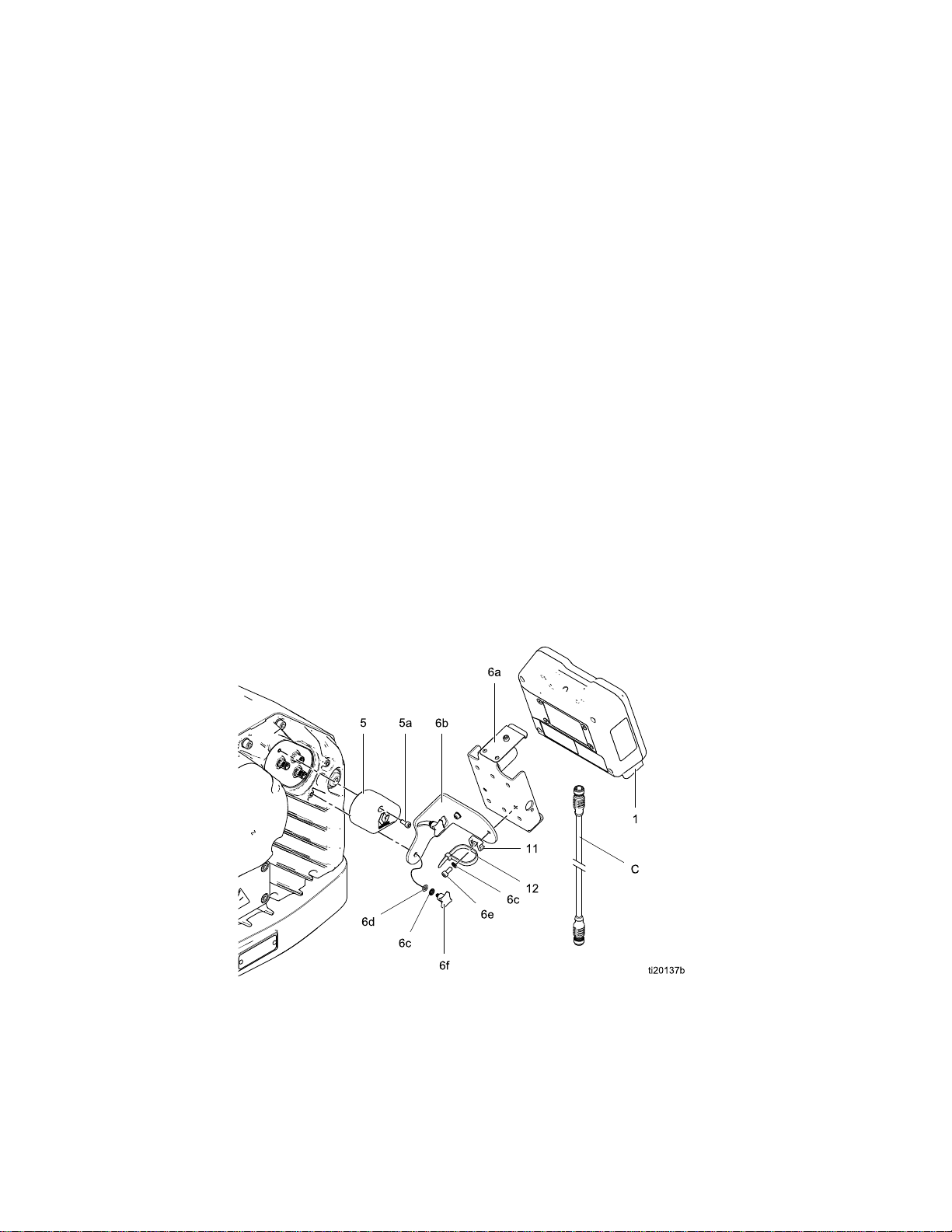
3.Assemblethebracketkit(6a-6f)andtheholder
andtie(11,12)asshown.
4.Installthemodule(1)inthebracket(6a),making
surethetabsatthebottomofthebracketengage
theslotsinthemodule,andthelipatthetopof
thebracketholdsthemodulesecurelyinplace.
5.Connecttheaccessorycable(C),usingthe
tie(12)asastrainreliefasshown.See
CableConnection,page5.
6.Restorepowertothemotor.
NOTE:
NOTE: NOTE:
differentmulti-unittopologies.
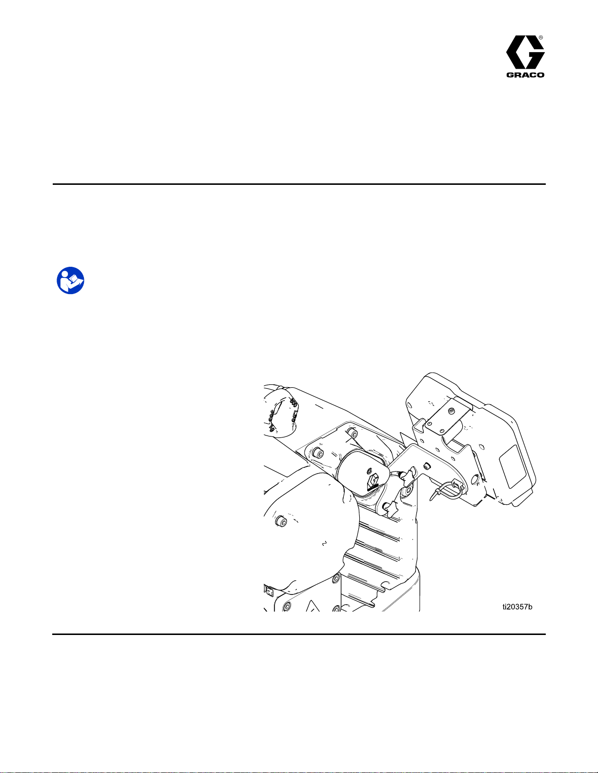
Figure1InstalltheControlModule(SinglePhase
ModelShown)
SeeAppendixCforinformationabout
4
3A2527H
Page 5
Installation
Cable
Cable Cable
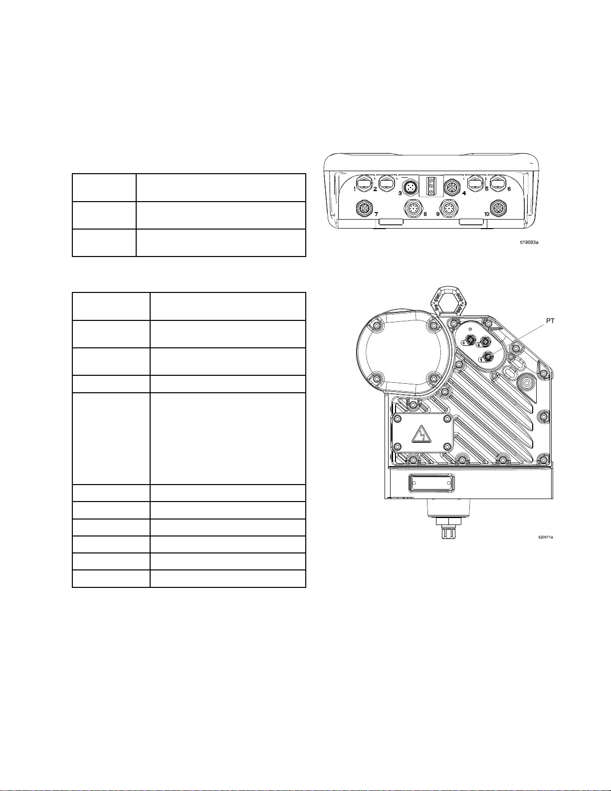
Orderanaccessorycable(C)fromTable1.ConnectthecabletoPort3onthebottomofthecontrolmodule
(seeFig.2).Connecttheotherendtothepowerterminal(PT)onthemotor(seeFig.3).Connectother
cablesasdescribedinTable2.
Table
Table Table
Cable
Cable Cable
No.
No. No.
16P911
16P912
Table
Table Table
ADCM
ADCM ADCM
Number
Number Number
1
2
Connection
Connection Connection
CAN
1 11CAN CAN
2 22ADCM ADCM
Cables
Cables Cables
Part
Part Part
ADCM
Port
Port Port
Description
Description Description
IntrinsicallysafeCANcable,female
xfemale,3ft(1m)
IntrinsicallysafeCANcable,female
xfemale,25ft(8m)
Cable
Connections
Cable Cable
Connections Connections
Connector
Connector Connector
FiberOpticRX-toFiberOptic
ConverterModule
FiberOpticTX-toFiberOptic
ConverterModule
Purpose
Purpose Purpose
Figure2ADCMConnectors
3
4
5
6
7
8BPRcontrol4-20mAoutput
9PrimaryTankLevelMonitor
10Pressuretransducer2
PowerandCANcommunication
•Start/Stopinput(pin2)
•Fillpumpoutput(pin3)
•Reedswitchinput(pin4)
•Agitatorhaltinput(pin4)
•Tankhighoutput(pin4)
•Tanklowoutput(pin4)
•Auxiliaryoutput(pin4)
FiberOpticRX-tonextADCM
FiberOpticTX-tonextADCM
Pressuretransducer1
Figure3MotorPowerTerminal
3A2527H5
Page 6

Operation
Operation
Operation Operation
Module
Module Module
TheControlModulehastwosetsofscreens:
RunandSetup.Fordetailedinformationsee
RunScreens,page9,andSetupScreens,page12.
Press
theSetupscreens.
InformationdisplayedontheRunandSteup
screenscorrespondstotheModbusRegisters.See
AppendixA-ModbusVariableMap,page30.
NOTE:
NOTE: NOTE:
loadrequirements.
Module
Module Module
Figure4isaviewofthecontrolmoduledisplayand
keys.Table2explainsthefunctionofthemembrane
keysonthecontrolmodule.Asyoumovethrough
thescreens,youwillnoticethatmostinformation
iscommunicatedusingiconsratherthanwords
tosimplifyglobalcommunication.Thedetailed
screendescriptionsinRunScreens,page9,and
SetupScreens,page12,explainwhateachicon
Screens
Screens Screens
totogglebetweentheRunscreensand
Thescreenautomaticallydimsbasedonthe
Keys
Keys Keys
represents.Thetwosoftkeysaremembranebuttons
whosefunctioncorrelateswiththescreencontentto
theimmediateleftofthebutton.
NOTICE
NOTICE NOTICE
Topreventdamagetothesoftkeybuttons,donot
pressthebuttonswithsharpobjectssuchaspens,
plasticcards,orngernails.
Figure4ControlModuleKeypadandDisplay
63A2527H
Page 7
Operation
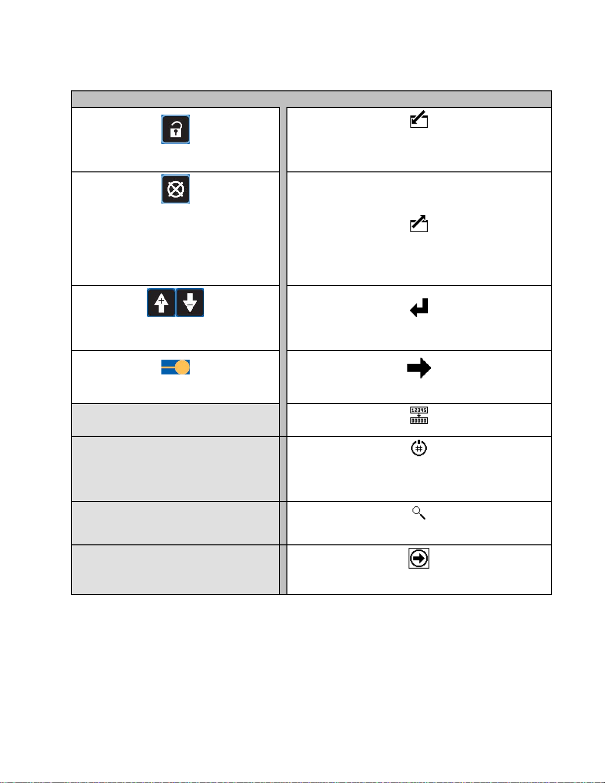
Table
Table Table
Cancel/Error
Cancel/Error Cancel/Error
causehasbeenxed.Whenthereisnoalarm
eldsonascreen,ortoincreaseordecrease
thenumericvaluesinaeldthatcanbeedited.
Module
3 33Module Module
Toggle:
Toggle: Toggle:
screensandSetupscreens.
toclear,thiskeysetstheactivepump’s
proletoStop.Alsousedtocancelthedata
enteredandreturntotheoriginaldata.
NOTE:Thepumpstopfunctioncanbe
disabledinSetupScreen16.
Up/Down
Up/Down Up/Down
Keys
Keys Keys
Membrane
Membrane Membrane
TogglebetweentheRun
Reset:
Reset: Reset:
Arrows:
Arrows: Arrows:
Clearthealarmafterthe
Movebetweenscreensor
Keys
Keys Keys
Softkeys
Softkeys Softkeys
Enter
Screen:
Enter Enter
Screen: Screen:
AlsochangesthefunctionoftheUp/Down
arrowssotheymovebetweendataeldson
thescreen,ratherthanbetweenscreens.
Enter:
Enter: Enter:
Presstoactivateaeldforeditingorto
acceptthehighlightedselectiononamenu.
Highlightdatathatcanbeedited.
Exit
Screen:
Exit Exit
Screen: Screen:
Exitdataediting.
Softkeys:
Softkeys: Softkeys:
Softkeyscolumnsatright.
Variesbyscreen.Seethe
Right:
Right: Right:
Movetotherightwheneditingnumberelds.Press
againtoaccepttheentrywhenalldigitsarecorrect.
Reset:
Reset: Reset:
Activate
Activate Activate
andonlyappearsonSetupScreens1–4iftheProle Prole
Lock
Lock Lock
Prole:
Prole: Prole:
boxischeckedonSetupScreen22,page22.
Presstoactivatetheprolejustedited.
Search:
Search: Search:
activepumpblinkforidentication.
Acknowledge:
Acknowledge: Acknowledge:
softwareupdatehasconcluded.
Resettotalizertozero.
Thissoftkeyisdisabledbydefault,
PressinRunScreen1tomakethe
Presstoacknowledgethata
Prole
3A2527H
7
Page 8
Operation
Screen
Screen Screen
Refertothissectionforinstructionsonnavigating
screens,enteringinformation,andmakingselections.
All
Screens
All All
Screens Screens
•Usetheupanddownarrowkeys
betweenscreens.
•Presstheenterscreenkey
Therstdataeldonthescreenishighlighted.
•Usethearrowkeystohighlightthedata
thatyouwanttochange.
•Presstheenterkeytoedit.
•Pressthecancelkeytocancel.
•Whenalldataiscorrect,presstheexitscreen
key
downarrowkeys tomovetoanew
screen,orthetoggleicon tomovebetween
SetupscreensandRunscreens.
Menu
Menu Menu
Navigation
Navigation Navigation
toexitthescreen.Thenusetheupand
Fields
Fields Fields
and
and and
Editing
Editing Editing
toenterascreen.
Check
Check Check
Acheckboxeldisusedtoenableordisablefeatures
inthesoftware.
tomove
•Presstheenterkey
•Thefeatureisenabledifacheck isinthebox.
Reset
Reset Reset
Thereseteldisusedfortotalizers.Pressthe
totalizerresetkey
Initial
Initial Initial
NOTE:
NOTE: NOTE:
Screens1through4,youmustsetupthesystem
parametersinSetupScreens5through22,as
follows.
1.Pressthelockicon toentertheSetup
2.ScrolltoSetupScreen5.
Box
Fields
Box Box
Fields Fields
totogglebetweenacheck
andanemptybox.
Field
Field Field
toresettheeldtozero.
Setup
Setup Setup
BeforecreatingthepumpprolesinSetup
screens.SetupScreen1appears.
•Usetheupanddownarrowkeys to
highlightthecorrectchoicefromthemenu.
•Presstheentericon
Number
Number Number
•Therstdigitintheeldishighlighted.Usethe
•Presstherightarrowkey
•Whenalldigitsarecorrect,presstherightarrow
Fields
Fields Fields
upanddownarrowkeys tochangethe
number.
digit.
keyagaintoaccept.
toselect.
tomovetothenext
3.SeeSetupScreen5,page15,andselectthe
lowerusedinyoursystem.
4.Continuesettingthesystemparameters
onSetupScreen6,page15through
SetupScreen22,page22.
5.ScrolltoSetupScreen1.Establish
theprolesforeachpump.See
SetupScreen1,page12through
SetupScreen4,page14.
83A2527H
Page 9
RunScreens
Run
Run Run
TheRunscreensdisplaycurrenttargetvaluesandperformanceforaselectedpumpandprole.Anyalarms
displayinthesidebarattherightofthescreen.Screens6–9and10–13displayalogofthelast20alarmsfor
theactivepump.
TheactivepumpandprolemaybechangedinRunScreens1,2,and3.
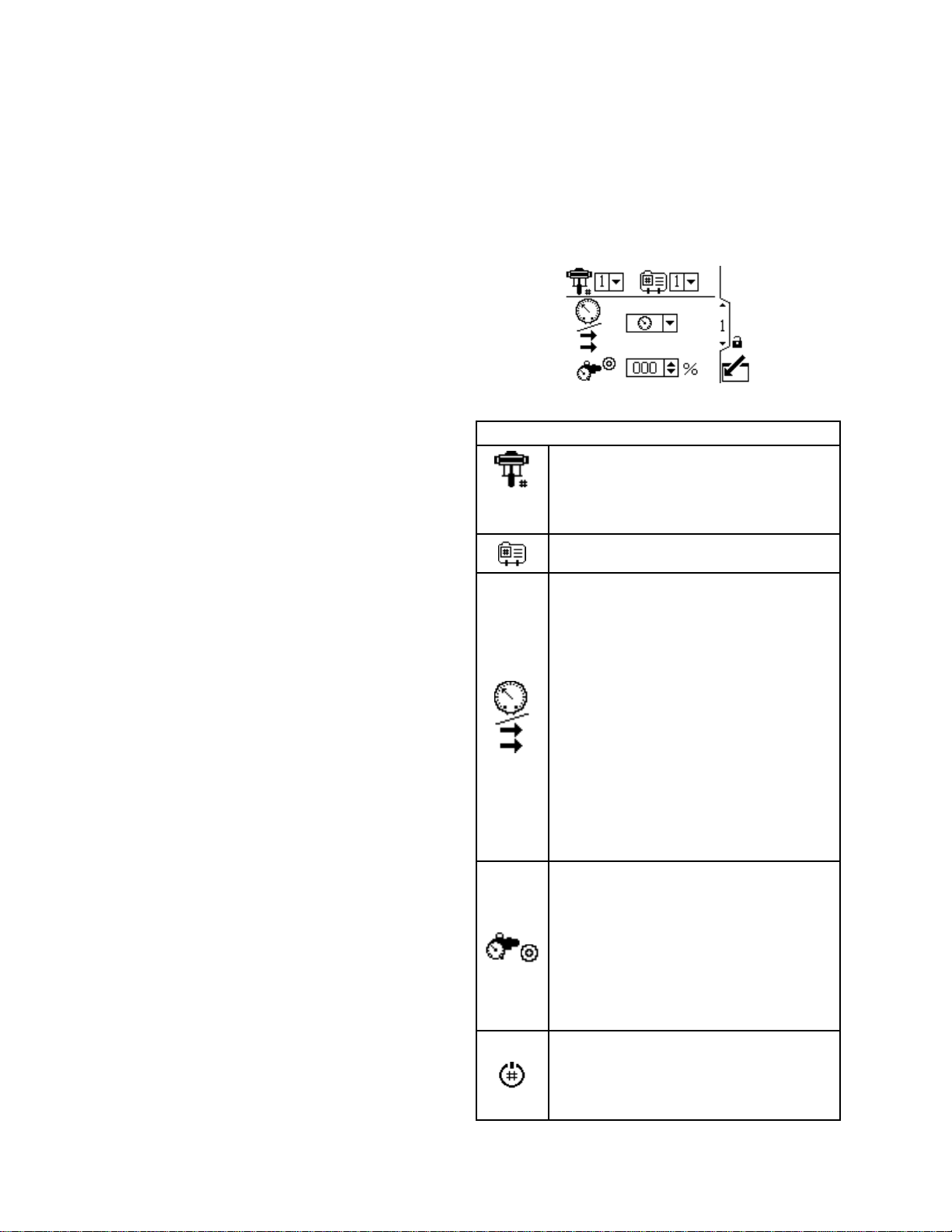
Run
Run Run
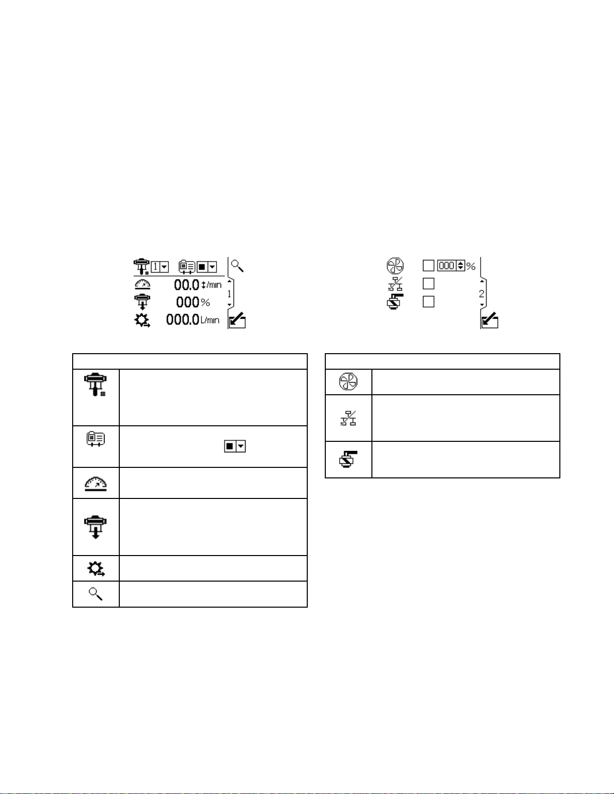
Thisscreendisplaysinformationforaselected
pumpandprole.Aboxaroundaniconindicates
whichmodetheactivepumpandproleisrunning
(pressureorow).
Figure5RunScreen1
Screens
Screens Screens
Screen
Screen Screen
1
1 1
Run
Screen
Run Run
Screen Screen
Forsystemswithmultiplepumpsand
onedisplay,selectthepump(1to8)
fromthemenu.
NOTE:Threephasesystemsdonot
supportmultiplepumps.
Selecttheprole(1to4)fromthemenu.
Selectthestopoption fromthe
menutostopthepump.
Displaysthecurrentpumpspeedin
cyclesperminute.
Key
1 11Key Key
Run
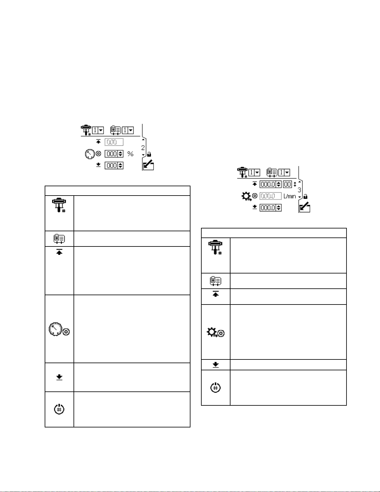
Run Run
Thisscreendisplaysinformationforcontrollingan
electricagitatorusingthesupervisortopasson
thecontrolsetpointtoaVariableFrequencyDrive
(VFD),alsoknownasaninverter.
Figure6RunScreen2
Screen
Screen Screen
2
2 2
Run
Screen
Run Run
Screen Screen
Selectthisboxandsetthespeed
setpointfortheagitatorfrom0–100%.
Selectthisboxtodisablenetworkcontrol
oftheagitatorandpreventtheIPKtouch
screenfrommodifyingtheVariable
FrequencyDrive/Invertersetpoint.
Selectthisboxandholdthesoftkey
buttontomanuallycontrolthellpump
solenoidoutput.
Key
2 22Key Key
Displaysthecurrentpumppressureasa
percentage.Ifatransducerisused,this
iconisreplacedbythepressureicon.
Tosetupapressuretransducer,see
SetupScreens8and9,page16.
Displayscurrentowrateinunitsas
selectedinSetupScreen15,page18.
Signalstheactivepumptoblinkcode9
foridentication.
3A2527H9
Page 10
RunScreens
Run
Run Run
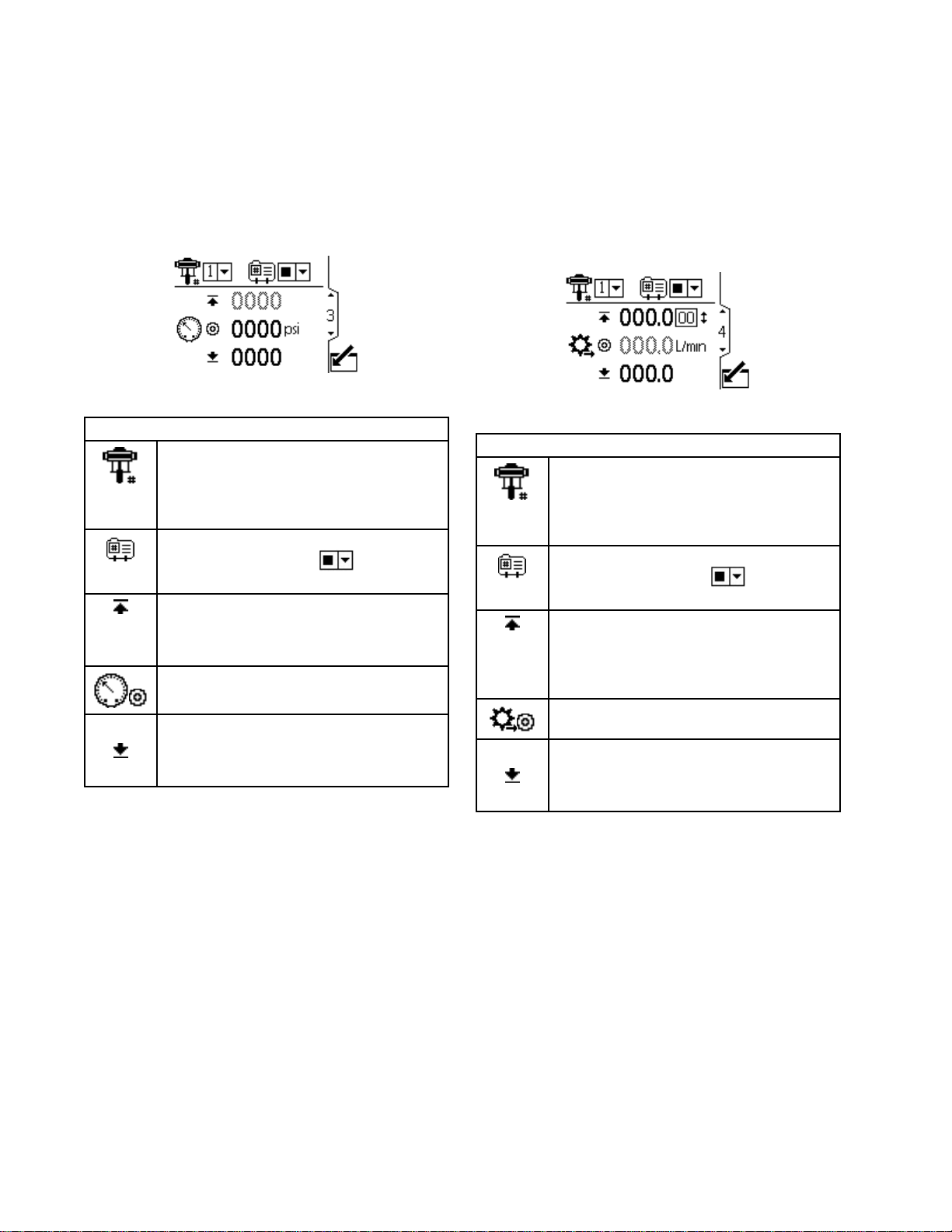
Thisscreendisplayspressuresettingsfortheactive
pumpandprole.Pressurecanbemeasuredinpsi,
bar,andMPa.
NOTE:
NOTE: NOTE:
setupselections.
Figure7RunScreen3,ShowninPressureMode
Screen
Screen Screen
Someeldsaregrayedout,dependingon
3
3 3
Run
Screen
Run Run
Screen Screen
Forsystemswithmultiplepumpsand
onedisplay,selectthepump(1to8)
fromthemenu.
NOTE:Threephasesystemsdonot
supportmultiplepumps.
Selecttheprole(1to4)fromthemenu.
Selectthestopoption
menutostopthepump.
Displaysthemaximumuidpressureas
selectedinSetupScreen2,page13.
SeeSetupScreen4,page14tosetor
disablethepressurealarms.
Displaysthetargetpressureasselected
inSetupScreen2,page13.
Displaystheminimumuidpressureas
selectedinSetupScreen2,page13.
SeeSetupScreen4,page14tosetor
disablethepressurealarms.
Key
3 33Key Key
fromthe
Run
Run Run
Thisscreendisplaysuidowsettingsfortheactive
pumpandprole.Fluidowcanbemeasuresinliters
perminute,gallonsperminute,ccperminute,ozper
minute,orcyclesperminute.
NOTE:
NOTE: NOTE:
setupselections.
Figure8RunScreen4,ShowninPressureMode
Screen
Screen Screen
Someeldsaregrayedout,dependingon
4
4 4
Run
Screen
Run Run
Screen Screen
Forsystemswithmultiplepumpsand
onedisplay,selectthepump(1to8)
fromthemenu.
NOTE:Threephasesystemsdonot
supportmultiplepumps.
Selecttheprole(1to4)fromthemenu.
Selectthestopoption fromthe
menutostopthepump.
Displaysthemaximumowrateand
maximumcyclerateasselected
inSetupScreen3,page13.See
SetupScreen4,page14tosetor
disabletheowalarms.
Displaysthetargetowrateasselected
inSetupScreen3,page13.
Displaystheminimumowrateas
selectedinSetupScreen3,page13.
SeeSetupScreen4,page14tosetor
disabletheowalarms.
Key
4 44Key Key
103A2527H
Page 11
RunScreens
Run
Run Run
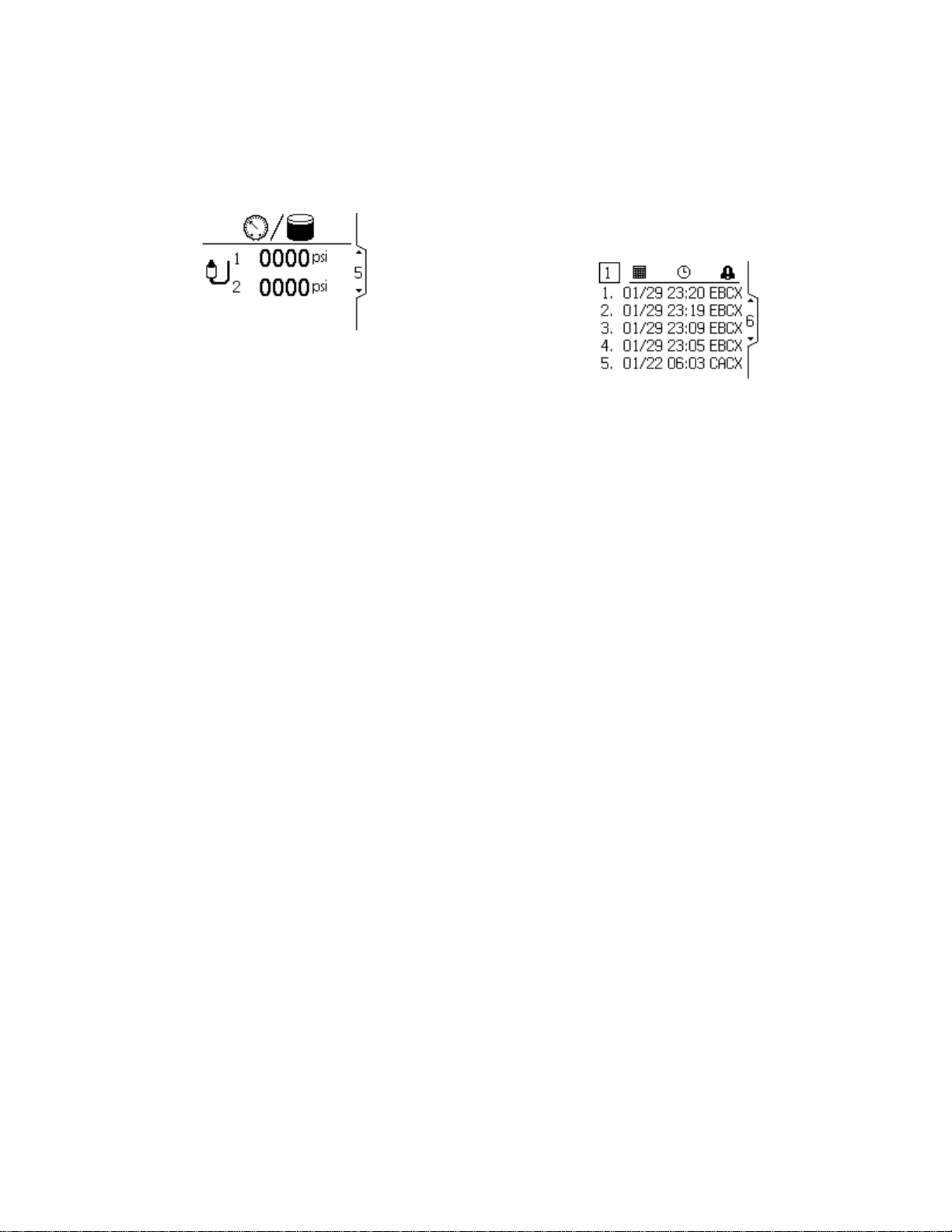
Thisscreendisplaysthecurrentpressurereadingsof
transducers1and2.Pressurecanbedisplayedas
psi,bar,orMPa.SeeSetupScreen15,page18.
Figure9RunScreen5
Screen
Screen Screen
5
5 5
Run
Run Run
RunScreens6–9(singleorx2parentpump)
and10–13(x2childpump)displayalogof
thelast20alarms,withdateandtime.The
currentlyactivepumpisdisplayedinaboxat
thetopleftofthescreen.Forerrorcodes,see
ErrorCodeTroubleshooting,page23.
Figure10RunScreen6
Screens
Screens Screens
6–9
and
6–9 6–9
10–13
and and
10–13 10–13
3A2527H
11
Page 12
SetupScreens
Setup
Setup Setup
UsetheSetupscreensforpump
settingsandaccessoryfeatures.See
ScreenNavigationandEditing,page8for
informationonhowtomakeselectionsandenter
data.
Inactiveeldsaregrayedoutonascreen.
NOTE:
NOTE: NOTE:
1–4,performtheinitialsetuponSetupScreens5–22
toestablishthecongurationforyoursystemand
affectthedisplayeddata.
Screens
Screens Screens
BeforesettingupprolesonSetupScreens
Setup
Setup Setup
Usethisscreentosettheoperatingmodefora
selectedpumpandprole.
Figure11SetupScreen1
Screen
Screen Screen
Forsystemswithmultiplepumpsand
onedisplay,selectthepump(1to8)
fromthemenu.
NOTE:Threephasesystemsdonot
supportmultiplepumps.
Selecttheprole(1to4)fromthemenu.
1
1 1
Setup
Setup Setup
Screen
Screen Screen
Key
1 11Key Key
Selecttheoperatingmode
(force/pressureorow)fromthe
menu.
•Inforce/pressuremode,themotor
adjuststhepumpspeedtomaintain
theuidpressurepercentageseton
SetupScreen2.Iftheowlimitis
reachedbeforethetargetpressure,
theunitstopsdrivingtothepressure
(ifsetasanalarm).
•Inowmode,themotormaintains
aconstantspeedtomaintainthe
targetowratesetonSetupScreen
3,regardlessoftheuidpressure,
uptothepump’smaximumworking
pressure.
Ifthesystemisequippedwithaback
pressureregulator(BPR),setthetarget
airpressuretotheBPRfrom0to100
percent(approximately1to100psi).
Leavetheeldsetto000forasystem
withnoBPR.Thisvaluerepresentsthe
percentagethatisclosedontheBPR.If
thevalueisgreaterthanzerobutthere
isnoBPRsystem,theL6CAerrorcode
appears.
Thissoftkeyisdisabledbydefault,and
onlyappearsiftheProle Prole
checkedonSetupScreen22,page22.
Presstoactivatetheprolethatyoujust
edited.
Prole
Lock
Lock Lock
boxis
12
3A2527H
Page 13
SetupScreens
Setup
Setup Setup
Usethisscreentosetthemaximum,target,and
minimumforce/uidpressureforaselectedpump
andprole.Inforce/pressuremode,youcanset
atargetforce/uidpressure.Inowmode,you
cansetamaximumforce/uidpressure.Ineither
force/pressureorowmode,youcansetaminimum
pressure.SeeSetupScreen4,page14,tospecify
howthesystemwillrespondifthepumpbeginsto
operateoutsideofthesetboundaries.
Figure12SetupScreen2
Screen
Screen Screen
Forsystemswithmultiplepumpsand
onedisplay,selectthepump(1to8)
fromthemenu.
NOTE:Threephasesystemsdonot
supportmultiplepumps.
Selecttheprole(1to4)fromthemenu.
Inowmode,setthemaximumpump
uidforce/pressure,asapercentageof
themaximumpressureofyourpump.
Thiseldisnotusedinpressuremode.
NOTE:Iftheproledoesnothavea
maximumpressuresetting,themotorwill
notrunanderrorcodeWSCXappears.
Inforce/pressuremode,settheforce/uid
pressuretargetasapercentageofthe
maximumpressureofyourpump.This
eldisnotusedinowmode.
NOTE:Ifclosedlooppressureis
enabled,thetargetpressureisdisplayed
asapressurevalue(psi,bar,MPa)rather
thanapercentageofmaximumpressure.
SeeSetupScreens8and9,page16to
enableclosedlooppressurecontrol.
Optionally,setaminimumpump
force/uidpressure,asapercentageof
themaximumforce/uidpressureofyour
pump.
Thissoftkeyisdisabledbydefault,and
onlyappearsiftheProle Prole
checkedonSetupScreen22,page22.
Presstoactivatetheprolethatyoujust
edited.
2
2 2
Setup
Setup Setup
Screen
Screen Screen
Key
2 22Key Key
Prole
Lock
Lock Lock
boxis
Setup
Setup Setup
Usethisscreentosetyourowratesettingsfora
selectedpumpandprole.Inpressuremode,you
willsetamaximumowrate.Inowmode,youwill
setatargetowrate.Ineitherpressureorowmode,
aminimumowratemaybeset.SeeSetupScreen
4tospecifyhowthesystemwillrespondifthepump
beginstooperateoutsideofthesetboundaries.
NOTE:
NOTE: NOTE:
valuethatcanbedisplayedis9999.Iftheeld
displays####,thesavedvalueisoutofrange.Go
toSetupScreen15,page18andchangetheow
ratetoalargerunit.Returntothisscreenandreduce
thesettingtoalowervaluethatwillbewithinthe
display’srange,thenresettheowrateunitsto
cc/min.
Figure13SetupScreen3
Screen
Screen Screen
Withowrateunitsofcc/min,themaximum
Forsystemswithmultiplepumpsand
onedisplay,selectthepump(1to8)
fromthemenu.
NOTE:Threephasesystemsdonot
supportmultiplepumps.
Selecttheprole(1to4)fromthemenu.
Inowmode,setatargetowrate.This
eldisnotusedinpressuremode.
Inpressuremode,setthemaximumow
rate.Thesoftwarecalculatesthenumber
ofpumpcyclesneededtoachievethat
owrate.Thiseldisnotusedinow
mode.
NOTE:Iftheproledoesnothavea
maximumowratesetting,themotorwill
notrunanderrorcodeWSC_appears.
Optionally,setaminimumowrate.
Thissoftkeyisdisabledbydefault,and
onlyappearsiftheProle Prole
checkedonSetupScreen22,page22.
Presstoactivatetheprolethatyoujust
edited.
3
3 3
Setup
Setup Setup
Screen
Screen Screen
Key
3 33Key Key
Prole
Lock
Lock Lock
boxis
3A2527H13
Page 14
SetupScreens
Setup
Setup Setup
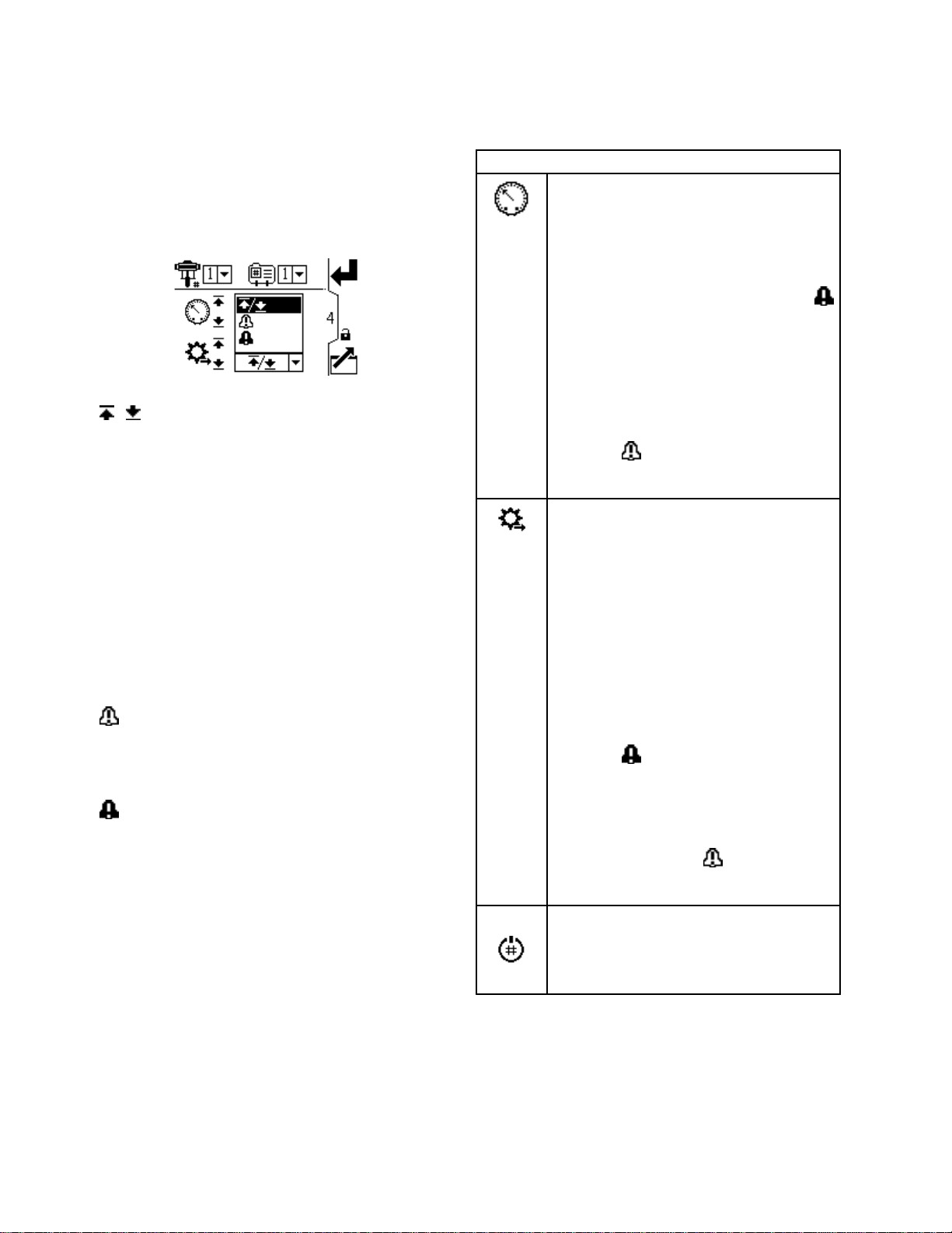
Usethisscreentospecifyhowthesystemresponds
ifthepumpbeginstooperateoutsideofthepressure
andowsettingsestablishedonSetupScreen2and
SetupScreen3.Theoperatingmode(pressureor
ow,setonSetupScreen1)determineswhichelds
areactive.
Figure14AlarmPreferenceMenu
• / Limit: Limit:
noalert.
–MaximumpressuresettoLimit:Thesystem
–MaximumowsettoLimit:Thesystemreduces
–MinimumpressureorowsettoLimit:The
–PressurelimiterrorsincludeP1I_,P2I_,P3I_,
–FlowrateerrorsincludeK1D_,K2D_,K3D_,and
•
problem,butthepumpmaycontinuetorunpast
themaximumorminimumsettingsforveseconds
untilthesystem’sabsolutepressureorow
boundariesarereached.
•Alarm: Alarm:
causeandshutsdownthepump.
NOTE:
NOTE: NOTE:
activemeasurementsarefromtheirsetlimits.
Screen
Screen Screen
Limit:
reducestheowifnecessarytopreventthe
pressurefromexceedingthelimit.
thepressureifnecessarytopreventtheow
fromexceedingthelimit.
systemtakesnoaction.Usethissettingforno
minimumpressureorowsetting.
andP4I_.
K4D_.
Deviation:
Deviation: Deviation:
Alarm:
Thesystemalertsyoutothealarm
Alerttriggertimevariesbasedonhowfar
4
4 4
Thepumpcontinuestorunandissues
Thesystemalertsyoutothe
Setup
Setup Setup
Toenablethepressurealarm:
•Line1(PressureMaximum):Select
Limit
Limit Limit
Forrunawaycontrol,setthemaximum
owtoAlarm Alarm
themaximumenteredonSetupScreen
3forveseconds,analarmsymbol
appearsonthescreenandthepump
shutsdown.
•Line2(PressureMinimum):Select
Limit
Limit Limit
Todetectapluggedlterorpipe,set
theminimumowtoDeviation Deviation
owratedropsbelowtheminimum
enteredonSetupScreen3,adeviation
symbol
warnyoutotakeaction.Thepump
continuestorun.
Toenabletheowratealarm:
•Line3(FlowMaximum):SelectLimit Limit
Deviation
Deviation Deviation
Topreventtheconnectedequipment
fromexcessivepressure,setthe
maximumpressuretoLimit.
•Line4(FlowMinimum):SelectLimit Limit
Deviation
Deviation Deviation
Forrunawaycontrol,settheminimum
pressuretoAlarm Alarm
thepumpdoesnotchangespeed,
butthebackpressurefalls.When
thepressurefallsbelowtheminimum
enteredonSetupScreen2,anAlarm
symbol
thepumpshutsdown.
Todetectapluggedlterorpipe,set
themaximumpressuretoDeviation Deviation
Whenthepressureexceedsthe
maximumenteredonSetupScreen2,
aDeviationsymbol
screentowarnyoutotakeaction.The
pumpcontinuestorun.
Thissoftkeyisdisabledbydefault,and
onlyappearsiftheProle Prole
checkedonSetupScreen22,page22.
Presstoactivatetheprolethatyoujust
edited.
Screen
Screen Screen
Deviation
,Deviation Deviation
Alarm
Deviation
,Deviation Deviation
,orAlarm Alarm
,orAlarm Alarm
4 44Key Key
,orAlarm Alarm
.Iftheowrateexceeds
,orAlarm Alarm
appearsonthescreento
Alarm
Alarm
Alarm
appearsonthescreenand
Prole
Key
Alarm
Alarm
.
.
.Ifahosebursts,
.
.
Deviation
appearsonthe
Lock
Lock Lock
.Ifthe
Limit
Limit
Deviation
boxis
,
,
.
14
3A2527H
Page 15
SetupScreens
Setup
Setup Setup
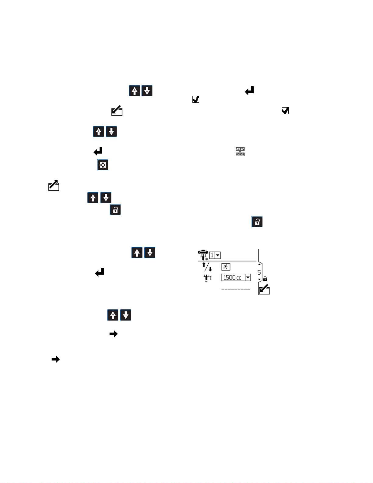
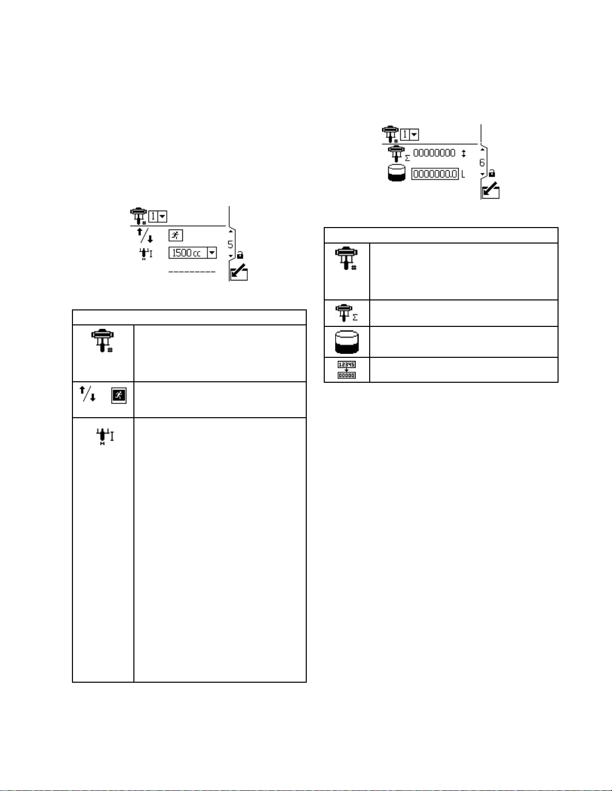
Usethisscreentosetthelowerpumpsize(cc)of
eachpump.Thedefaultisblank;selectthecorrect
lowersize,orcustom.Ifcustomisselected,enterthe
sizeofthelowerincc.Thisscreenalsoactivatesjog
mode,allowingyoutopositionthemotor/pumpshaft
forconnectionordisconnection.
NOTE:
NOTE: NOTE:
theselectedloweris750cc,topreventexceedingthe
pressureratingofthelower.
Figure15SetupScreen5
Screen
Screen Screen
Themotorwilllimititspressureoutputwhen
5
5 5
Setup
Setup Setup
Forsystemswithmultiplepumpsand
onedisplay,selectthepump(1to8)
fromthemenu.
NOTE:Threephasesystemsdonot
supportmultiplepumps.
Selecttoenablejogmode.Usethe
arrowkeystomovethemotoror
pumpshaftupordown.
Selectthecorrectpumplowersize
fromthemenu.Thedefaultisblank.
Ifcustomisselected,aeldopens
foryoutoinputthesizeofthelower
incc.
Screen
Screen Screen
Key
5 55Key Key
Setup
Setup Setup
Usethisscreentoviewthegrandtotalizervalueand
tosetorresetthebatchtotalizer.
Figure16SetupScreen6
Screen
Screen Screen
Forsystemswithmultiplepumpsand
onedisplay,selectthepump(1to8)
fromthemenu.
NOTE:Threephasesystemsdonot
supportmultiplepumps.
Displaysthecurrentgrandtotalofpump
cycles.Thiseldcannotbereset.
Displaysthebatchtotalinselected
volumeunits.
Resetsthebatchtotalizertozero.
6
6 6
Setup
Setup Setup
Screen
Screen Screen
Key
6 66Key Key
•Supplypumps
–145cc
–180cc
–220cc
–290cc
•Circpumps
–750cc*
–1000cc
–1500cc
–2000cc
–2500cc
*When750ccisselected,the
maximumforceiscappedto75%
topreventoverpressurizingthe
pump.
3A2527H15
Page 16

SetupScreens
Setup
Setup Setup
Usethisscreentosetthemaintenanceinterval(in
cycles)foreachpump.Thescreenalsodisplaysthe
currentcyclecount.ErrorcodeMND_appearswhen
thecounterreaches0(zero).
Figure17SetupScreen7
Screen
Screen Screen
Forsystemswithmultiplepumpsand
onedisplay,selectthepump(1to8)
fromthemenu.
NOTE:Threephasesystemsdonot
supportmultiplepumps.
Setthemaintenanceinterval(incycles)
foreachpump.
7
7 7
Setup
Setup Setup
Screen
Screen Screen
Key
7 77Key Key
Setup
Setup Setup
Usethesescreenstosetupthepressuretransducers.
Thescreensareidentical,exceptScreen8isfor
transducer1andScreen9isfortransducer2.
Selectingatransducerandapumpactivatesclosed
looppressurecontrol.
NOTE:
NOTE: NOTE:
transducertobeinstallednearthepumpoutlet.
Figure18SetupScreens8and9(Screen8shown)
Screens
Screens Screens
Closedlooppressurecontrolrequiresthe
Setup
Setup Setup
Selectfromthemenuoptions(500psior
5000psi)toenablethetransducer.
Thisoptionenablesclosedlooppressure
controlandassignsthetransducertoa
pump.
and
8 88and and
Screens
Screens Screens
9
9 9
and
8 88and and
Key
9 99Key Key
•Forsystemswithmultiplepumpsand
onedisplay,selectthepump(1to8)
fromthemenu.
•Forthreephasepumps,selectpump
1.
Enterthecalibrationscalefactorfromthe
transducerlabel.
Enterthecalibrationoffsetvaluefromthe
transducerlabel.
Displaysthecurrenttransducerreading.
163A2527H
Page 17

SetupScreens
Setup
Setup Setup
Thesescreensareauto-populatedbythesoftware.
Screen10displaystheserialnumbersofmotors1–4,
andScreen11displaystheserialnumbersofmotors
5–8.
NOTE:
NOTE: NOTE:
pumpuponeposition.Forexample,ifAD00001is
changedtobepump4,AD00002willbecomepump
1,AD00003willbecomepump2,andsoon.
Figure19SetupScreens10and11(Screen10
shown)
Screens
Screens Screens
Changingthepumporderwillshifteveryother
10
and
10 10
11
and and
11 11
Setup
Setup Setup
Thesescreensareauto-populatedbythesoftware.
Screen10displaysthesoftwareversionnumbers
ofmotors1–4,andScreen11displaysthesoftware
versionnumbersofmotors5–8.
Figure20SetupScreens12and13(Screen12
shown)
Screens
Screens Screens
12
and
12 12
13
and and
13 13
3A2527H
17
Page 18

SetupScreens
Setup
Setup Setup
Usethisscreentosetyourmodbuspreferences.
NOTE:
NOTE: NOTE:
whichcannotbesetorchangedbytheuser:
Figure21SetupScreen14
Screen
Screen Screen
Thefollowingarexedmodbussettings,
DataBits:8
StopBits:2
Parity:None
Forsystemswithmultiplepumpsand
onedisplay,selectthepump(1to8)
fromthemenu.
NOTE:Threephasesystemsdonot
supportmultiplepumps.
Selectlocal orremote from
themenu.Thissettingappliestothe
selectedpumponly.
Localmodeallowsyoutoviewchanges
overthemodbusnetwork,butyoucannot
makechangesoverthemodbusnetwork.
Remotemodeallowsyoutobothview
andchangeinformationoverthemodbus
network.
EnterorchangetheModbusnodeID.
Thevalueisbetween1and246.Each
pumprequiresauniquenodeID,which
identiesthatpumpifmorethanone
pumpisconnectedtothedisplay.
Selecttheserialportbaudratefromthe
menu.Thisisasystem-widesetting.
14
14 14
Setup
Setup Setup
Screen
Screen Screen
14
14 14
Setup
Setup Setup
Usethisscreentocongureandcontrolthetankll
featureandIntelligentPaintKitchenperipherals.
NOTE:Thealerttriggertimevariesbasedonhowfar
activemeasurementsarefromtheirsetlimits.
Figure22SetupScreen15
Key
Key Key
Screen
Screen Screen
Selectthisboxtomanuallyactivatethe
llsolenoidoutputonport4,pin3.
NOTE:Thenon-editableboxshowsthe
statusofthemodbusregister.
Selectthisboxtoenablethetankto
automaticallyll.Youcanthensetthe
lllevels.
Congurethelowllpumpow
noticationforadeviationoranalarm
andsetthetime-outvalueinseconds.
Ifa1%levelchangeisnotdetected
withthetimeoutperiodinseconds,the
systemtakesactionbasedontheevent
type.
15
15 15
Setup
Setup Setup
Screen
Screen Screen
Whenthetanklevelreachesthis
level,thellsolenoidturnsoff.
Thisvaluecannotbehigherthan
thelevelbelow.
Whenthetanklevelreachesthis
level,thellsolenoidturnson.
Thisvaluecannotbelowerthan
thelevelabove.
15
Key
15 15
Key Key
•38400kbps
•57600kbps(default)
•115200kbps
183A2527H
Page 19

SetupScreens
Setup
Setup Setup
Usethisscreentomonitor,setup,andcontrol
theIntelligentPaintKitchenperipherals.Formore
information,seetheSetUpPeripheralssectionof
theIntelligentPaintKitchenmanual3A4030.NOTE:
Thesecondeldvaries,dependingonthemenu
selectioninthersteld.
Screen
Screen Screen
Selecttheconnectedperipheralfromthemenu.
16
16 16
ConguresPort4pin4asaninputtoallowareedswitchtobeconnected.
Thecurrentreedswitchcyclerateappearsnexttothecyclerateicon incycles
perminute.
ConguresPort4pin4asaninputtoallowapressureswitchtobeconnected.Ifthe
drumcoverisliftedwhilethiscongurationisproperlyconnected,theagitatorshuts
down.
Thecurrentinputstatusappearsintheagitatorstatuseld .
NOTE:ASupervisorModuleisrequiredforthisfunction.
Setup
Setup Setup
Figure23SetupScreen16,ReedSwitchOption
Shown
Screen
Screen Screen
16
Key
16 16
Key Key
ConguresPort4pin4asanoutputtoallowfortheconnecteddevicetoreceivean
alarmwhenthelevelofthePrimaryTankisabovethevaluethatisdenedinthe
PrimaryTankHigheld .
ThisvalueisapercentageofthetotallevelofthePrimaryTank.
ConguresPort4pin4asanoutputtoallowfortheconnecteddevicetoreceivean
alarmwhenthelevelofthePrimaryTankisbelowthevaluethatisdenedinthe
PrimaryTankLoweld .
ThisvalueisapercentageofthetotallevelofthePrimaryTank
ConguresPort4pin4asanoutputtoallowforanothersolenoidtobeconnected
andcontrolledfromthedevice.
Selectthemanualoutputbox andholdthebuttontocontroltheauxiliary
solenoidmanually.Afteryoureleasethebutton,themanualactivationisterminated.
Allowsfortheconnecteddevicetoreceiveanalarmwhentheleveloftheprimarytankisabove
thevaluethatisdenedinthiseld.
Allowsfortheconnecteddevicetoreceiveanalarmwhentheleveloftheprimarytankisbelow
thevaluethatisdenedinthiseld.
3A2527H19
Page 20

SetupScreens
Setup
Setup Setup
Usethisscreentosetuptheinputscaling(radarlevel
sensor)for4–20mAdevicesandturnonthecurrent
loop(Port8andPort9oftheADCM).
Figure24SetupScreen17
Screen
Screen Screen
MonitorthebackpressureregulatormA
output.
SetthevalueforP9(Port9)between4
and20.
Selectthisboxtoturnonthe4-20mA
supply.Setthenumericalvaluesforthe
scalingceilingfor4-20mAsignal.
17
17 17
Setup
Setup Setup
Screen
Screen Screen
17
Key
17 17
Key Key
Setup
Setup Setup
Thisscreenisforenablingamodbuscommunications
alarmanddisablingtheStopPumpfunctionofthe
Cancelkey.
Figure25SetupScreen18
Screen
Screen Screen
Selectthemodbusalarmtype:
SelectthisboxtomakeCAN
communicationadeviationthat
doesnotshutdownthepump.
SelectthisboxtodisabletheStopPump
functionoftheReset/Cancelkey.
Enableordisablethebacklightandset
thetime-outvalveinminutes.
18
18 18
Setup
Setup Setup
Screen
Screen Screen
None
Deviation
Alarm
16
Key
16 16
Key Key
203A2527H
Page 21

SetupScreens
Setup
Setup Setup
Usethisscreentoenableordisabletherun/stop
switchandautorestart.
Figure26SetupScreen19
Screen
Screen Screen
Enableordisabletherun/stop
switch.Thedefaultsettingis
disabled.SeeRun/StopSwitchKit
inAccessories,page29.
Whenenabled,thiscongurationallows
therun/stopswitchtopausethepump
whileinaprole.Whentherun/stop
switchisactive,thefollowingpop-up
appears:
19
19 19
Setup
Setup Setup
Screen
Screen Screen
19
19 19
Setup
Setup Setup
Usethisscreentosettheunitsforpressure,totals,
andow.
Figure27SetupScreen20
Key
Key Key
Screen
Screen Screen
Selectthepressureunits:
•psi
•bar(default)
•MPa
Selectthevolumeunits:
•liters(default)
•gallons
•cc
Selecttheowrateunits:
20
20 20
Setup
Setup Setup
Screen
Screen Screen
20
Key
20 20
Key Key
Disabletheremotestartfunctionover
modbus.
Whenenabledalongwiththerun/stop
switch,youmusttoggletherun/stop
switchwhengoingfromprole0
(stopped)torunbeforethepumpcan
start.Whentherun/stopswitchisactive,
thefollowingpop-upappears:
Enableordisableautorestart.The
defaultsettingisdisabled.Ifenabled,the
unitresumesoperationattheprolethat
wassetbeforetheunitwasturnedoff.
•L/min(default)
•gpm
•cc/min
•oz/min
•cycles/min
Selectthesystemmode(singleorx2).
Ifyouareinsinglemodebutconnected
tox2orinx2modebutconnectedto
single,errorcodeWNNXappears.
3A2527H
21
Page 22

SetupScreens
Setup
Setup Setup
Usethisscreentosetyourdateformat,date,time,
orforcearestartofthesystemwhenupdatingthe
software(updatetokeninsertedintothedisplay).
Afterthesoftwareupdateiscompletedsuccessfully,
thetokenmustberemovedpriortoselectingthe
Acknowledgekeyorpowercyclingthedisplay.Ifan
updatewasconcludedandthetokenisnotremoved,
pressingtheAcknowledgekeyrestartstheupdate
process.
NOTE:
NOTE: NOTE:
Programming,page48forinstructionsonsoftware
updating.Softwareupdateisdisruptivetoallpumps
connectedtothedisplay.Allpumpsattachedto
thedisplaymustnotbepumpingmaterialwhenthe
softwareupdateisinitiated.
Figure28SetupScreen21
Screen
Screen Screen
RefertoAppendixD-ControlModule
21
21 21
Setup
Setup Setup
Usethisscreentoenterapasswordthatwillbe
requiredtoaccesstheSetupscreens.Thisscreen
alsodisplaysthesoftwareversion.
Figure29SetupScreen22
Screen
Screen Screen
Enterthe4–digitpassword.
Checktheboxtolockouttheagitator
eldintheRunscreens.
Checktheboxtolockouttheproleeld
ontheRunscreens..
22
22 22
Setup
Setup Setup
Screen
Screen Screen
22
Key
22 22
Key Key
Setup
Setup Setup
Selectyourpreferreddateformatfrom
themenu.
•MM/DD/YY
•DD/MM/YY(default)
•YY/MM/DD
Setthecorrectdate.
Setthecorrecttime.
Performasoftrestartofthesystem.
Screen
Screen Screen
18
Key
18 18
Key Key
22
3A2527H
Page 23

ErrorCodeTroubleshooting
Error
Error Error
Errorcodescantakethreeforms:
•Alarm
downthepump.
•Deviation
maycontinuetorunpastthesetlimitsuntilthe
system’sabsolutelimitsarereached.
•Advisory
tooperate.
NOTE:
NOTE: NOTE:
pressure(Pcodes)canbedesignatedasalarmsor
deviations.SeeSetupScreen4,page14.
Display
Display Display
Code
Code Code
NoneBasic6Alarm
Code
Code Code
:alertsyoutothealarmcauseandshuts
:alertsyoutotheproblem,butpump
:informationonly.Pumpwillcontinue
OnAdvancedmotors,ow(Kcodes)and
Applicable
Applicable Applicable
Motor
Motor Motor
Troubleshooting
Troubleshooting Troubleshooting
Blink
Blink Blink
Code
Code Code
Alarm
Alarm Alarm
Deviation
Deviation Deviation
or
or or
NOTE:
NOTE: NOTE:
thecodeisassociatedwiththedisplayonly.
NOTE:
NOTE: NOTE:
codeisaplaceholderforthenumberofthepump
wheretheeventoccurred.
NOTE:
NOTE: NOTE:
indicatoronthemotor.Theblinkcodegivenbelow
indicatesthesequence.Forexample,blinkcode1–2
indicates1blink,then2blinks;thesequencethen
repeats.
NOTE:
NOTE: NOTE:
indicatorofwhichpumpisactive(
beenpushed,seeRunScreen1,page9).
TheModeSelectknobissetbetweenPressure and
Flow
Intheerrorcodeslistedbelow,an“X”means
Intheerrorcodeslistedbelow,a“_”inthe
Theblinkcodeisdisplayedusingthepower
Ablinkcodeof9isnotanerrorcode,butan
Description
Description Description
.Settheknobtothemodeyouwant.
softkeyhas
NoneBasicand
A4N_
A4N_ A4N_
CAC_
CAC_ CAC_
CAD_
CAD_ CAD_
CAG_
CAG_ CAG_
C3G_
C3G_ C3G_
C4G_
C4G_ C4G_
CBN_
CBN_ CBN_
CCC_
CCC_ CCC_
CCN_
CCN_ CCN_
END_
END_ END_
9None
Advanced
6AlarmThemotorcurrentexceeded13Aorthehardwareovercurrent
AdvancedNoneAlarm
Advanced2–3Alarm
NoneDeviation
AdvancedNoneDeviation
AdvancedNoneAlarm
Basicand
Advanced
Advanced3–7AlarmNodisplaywasdetectedatstartup.
Basicand
Advanced
Basicand
Advanced
2–4Deviation
3–6Alarm
5–6Advisory
Ablinkcodeof9isnotanerrorcode,butanindicatorof
whichpumpisactive.
trippedat20A.
DisplaydetectsalossofCANcommunication.Flashing
alarmappearsonthedisplay,andtheblinkcodeoccurs.
UnitdetectsalossofCANcommunication.Thisalarmisonly
logged.Noashingalarmappearsonthedisplay,butthe
blinkcodedoesoccur.
ThePLChasstoppedpingingtheregisterforthesolenoid.
Displaydetectsalossofmodbuscommunicationwhen
modbusdeviationisenabledonSetupScreen16.
Displaydetectsalossofmodbuscommunicationwhen
modbusalarmisenabledonSetupScreen16.
Temporarycircuitboardcommunicationfailure.
Circuitboardcommunicationfailure.
Acalibrationoftheencoderandstrokerangeisinprogress.
ENN_
ENN_ ENN_
E5D_
E5D_ E5D_
3A2527H23
AdvancedNoneAdvisory
Basicand
Advanced
1–7Deviation
Duallowersystemcalibrationcompletedsuccessfully.
Calibratecoderfailure.
Page 24

ErrorCodeTroubleshooting
Display
Display Display
Code
Code Code
E5F_
E5F_ E5F_
E5N_
E5N_ E5N_
E5S_
E5S_ E5S_
E5U_
E5U_ E5U_
EBC_
EBC_ EBC_
ELI_
ELI_ ELI_
ERR0_
ERR0_ ERR0_
F1F0
F1F0 F1F0
F2F0
F2F0 F2F0
K1D_
K1D_ K1D_
Applicable
Applicable Applicable
Motor
Motor Motor
AdvancedNoneAdvisory
Basicand
Advanced
AdvancedNoneAdvisoryDuallowersystemcalibrationstoppedorinterrupted.
AdvancedNoneAdvisory
AdvancedNoneAdvisory
Basicand
Advanced
Basicand
Advanced
Advanced1–2AlarmFlowisbelowminimumlimit.
Blink
Blink Blink
Code
Code Code
2–7Deviation
4–5DeviatoinDeviationhotboardreset.
2–5Deviatoin
NoneAlarm
NoneDeviation
Alarm
Alarm Alarm
Deviation
Deviation Deviation
or
or or
Duallowersystemcalibrationerror.Systemrunningtoo
rapidlytoperformcalibration.
Calibratestrokefailed.
Duallowersystemcalibrationunsteady.Systemcouldnot
determineoptimumsetting.
Run/StopswitchinStopposition(closed).
Deviationsoftwareerror.
Fillpumpownotdetected.Theprimarytanklevelhasnot
increasedwiththenoowtimeoutwindowandthenoow
timeouteventissettoalarm.
Fillpumpownotdetected.Theprimarytanklevelhasnot
increasedwiththenoowtimeoutwindowandthenoow
timeouteventissettodeviation.
Description
Description Description
K2D_
K2D_ K2D_
K3D_
K3D_ K3D_
K4D_
K4D_ K4D_
L1A0
L1A0 L1A0
L2A0
L2A0 L2A0
L4A0
L4A0 L4A0
L6CA
L6CA L6CA
L6CB
L6CB L6CB
MND_
MND_ MND_
P1D_
P1D_ P1D_
AdvancedNoneDeviationFlowisbelowminimumlimit.
AdvancedNoneDeviationFlowexceedsmaximumtarget;alsoindicatespumprunaway
conditionexists.
Basicand
Advanced
AdvancedNoneAdvisoryMaintenancecounterisenabledandcountdownreached
AdvancedNoneDeviationUnbalancedload.DualLowersystem—P1D1=Motor1is
1AlarmFlowexceedsmaximumtarget;alsoindicatespumprunaway
conditionexists.
NoneAlarm
NoneDeviationTheprimarytanklevelisbelowtheprimarytanklevellow
NoneAlarmTheprimarytanklevelisabovetheprimarytanklevelhigh
NoneDeviationPort8isenabledandthecurrentdrawislessthan4mA.
NoneDeviationPort9isenabledandthecurrentdrawislessthan4mA.
Theowrateisabovethecurrentproleowlimitseton
ProleScreen3.
deviationsetpoint.
alarmsetpoint.
TheBPRisrequestingavaluegreaterthan0%.Verifythat
thedeviceisconnected.
Verifythatthedeviceisconnected.
zero(0).
requiringlessforcetoholdspeed;pumplowermayneed
service.P1D2=Motor2isrequiringlessforcethanmotor
1toholdspeed.
P9D_
P9D_ P9D_
P1I_
P1I_ P1I_
24
AdvancedNoneDeviation
Advanced1–3AlarmPressureisbelowminimumlimit.
Majorunbalancedload—seeP1D_(P9D_ishigher
magnitude)
3A2527H
Page 25

ErrorCodeTroubleshooting
Display
Display Display
Code
Code Code
P2I_
P2I_ P2I_
P3I_
P3I_ P3I_
P4I_
P4I_ P4I_
P5DX
P5DX P5DX
P6CA
P6CA P6CA
P6CB
P6CB P6CB
P6D_
P6D_ P6D_
T2D_
T2D_ T2D_
T3D_
T3D_ T3D_
T4D_
T4D_ T4D_
V1I_
V1I_ V1I_
V2I_
V2I_ V2I_
Applicable
Applicable Applicable
Motor
Motor Motor
AdvancedNoneDeviationPressureisbelowminimumlimit.
AdvancedNoneDeviationPressureexceedsmaximumtarget.
Advanced1–4AlarmPressureexceedsmaximumtarget.
AdvancedNoneDeviationMorethanonepumpisassignedtoatransducer.The
AdvancedNoneDeviationForunitswithoutclosedlooppressurecontrol:Transducer
or
Advanced1–6AlarmForunitswithclosedlooppressurecontrol:Transduceris
Basicand
Advanced
Basicand
Advanced
Basicand
Advanced
Basicand
Advanced
Basicand
Advanced
Blink
Blink Blink
Code
Code Code
3–5AlarmInternalthermistordisconnectedormotortemperatureis
5
4–6Alarm
2AlarmBrownout;voltagesuppliedtomotoristoolow.
NoneDeviationBrownout;voltagesuppliedtomotoristoolow.
Alarm
or
Alarm Alarm
or or
Deviation
Deviation Deviation
assignmentforthattransducerisautomaticallyclearedunder
thiscondition.Usermustreassign.
(AorB)isenabledbutnotdetected.
enabledbutnotdetected.
below0°C(32°F).
Deviation
Motorovertemperature.Motorwillthrottleitselftostaybelow
85°C(185°F)internally.
Motorovertemperature.Motorwillthrottleitselftostaybelow
85°C(185°F)internally.
Description
Description Description
V1M_
V1M_ V1M_
V3I_
V3I_ V3I_
V4I_
V4I_ V4I_
V9M_
V9M_ V9M_
WCW_
WCW_ WCW_
WMC_
WMC_ WMC_
WNC_
WNC_ WNC_
WNN_
WNN_ WNN_
WSC_
WSC_ WSC_
Basicand
Advanced
Basicand
Advanced
Basicand
Advanced
Basicand
Advanced
AdvancedNoneAlarm
Basicand
Advanced
Basicand
Advanced
AdvancedNoneAlarm
AdvancedNoneDeviation
2–6Alarm
NoneDeviationVoltagesuppliedtomotoristoohigh.
3AlarmVoltagesuppliedtomotoristoohigh.
7
4–5Alarm
3–4Alarm
AlarmLowsupplyvoltagedetectedatstartup.
ACpowerislost.
Systemtypemismatch;motorisanE-FloDCduallower
systemandthedisplaycongurationdoesnotmatch.
Changethedisplay’ssystemtypeontheSetupUnitsscreen
(screen15).
Internalsoftwareerror.
Softwareversionsdonotmatch.
Systemtypemismatch;motorisanE-FloDCsinglelower
systemandthedisplaycongurationdoesnotmatch.
Changethedisplay’ssystemtypeontheSetupUnitsscreen
(screen12induallowermode).
Proleissetto0pressureor0ow.
3A2527H25
Page 26

ErrorCodeTroubleshooting
Display
Display Display
Code
Code Code
WSD_
WSD_ WSD_
WXD_
WXD_ WXD_
Applicable
Applicable Applicable
Motor
Motor Motor
Advanced1–5Alarm
Basicand
Advanced
Blink
Blink Blink
Code
Code Code
4Alarm
Alarm
Alarm Alarm
Deviation
Deviation Deviation
or
or or
Invalidlowersize;occursiftheunitisoperatedbeforesetting
upthelowersize.
Aninternalcircuitboardhardwarefailureisdetected.
Description
Description Description
263A2527H
Page 27

Parts
Parts
Parts Parts
24P822
24P822 24P822
Ref
Ref Ref
124P821
1a▲16P265LABEL,warning,
1b▲16P265LABEL,warning,
1c▲16P265LABEL,warning,
5
5a
624P823
Part
Part Part
24N910
———
Control
Control Control
Module
Module Module
Description
Description Description
DISPLAYKIT,control
module;includes
item1a;seemanual
332013forapprovals
informationaboutthe
bareADCMmodule
English
French
Spanish(shipped
loose)
CONNECTOR,
jumper;includes
item5a
SCREW,cap,socket
head;M5x40mm
BRACKETKIT,
controlmodule;
includesitems6a-6f
Kit
Kit Kit
(Single
(Single (Single
Phase,
Phase, Phase,
Qty
Qty Qty
1
1
1
1
1
1
1
Side
Side Side
Ref
Ref Ref
6a
6b
6c
6d
6e
6f
11
12
▲ReplacementDangerandWarninglabels,tags,
andcardsareavailableatnocost.
Itemsmarked———arenotavailableseparately.
Cable(C)isshownforreferencebutisnotincluded
inthekit.Orderspeciedlengthseparately.See
CableConnection,page5.
Part
Part Part
———
———
———
———
———
———
———
———
Mount)
Mount) Mount)
Description
Description Description
BRACKET,control
module
BRACKET,mounting
LOCKWASHER,
externaltooth;M5
WASHER;M5
SCREW,cap,socket
head;M5x12mm
KNOB;M5x0.8
HOLDER,tie
STRAP,tie
Qty
Qty Qty
1
1
4
2
2
2
1
1
3A2527H
27
Page 28

Parts
17V232
17V232 17V232
Ref
Ref Ref
1
1a▲
1b▲16P265LABEL,warning,
624P823
6a*
6b
6c
Part
Part Part
———
———
———
———
———
Control
Control Control
Module
Module Module
Description
Description Description
DISPLAYKIT,control
module;includes
item1a;seemanual
332013forapprovals
informationaboutthe
bareADCMmodule
LABEL1
French
BRACKETKIT,
controlmodule;
includesitems6a-6f
BRACKET,control
module
BRACKET,mounting
LOCKWASHER,
externaltooth;M5
Kit
(Three
Kit Kit
(Three (Three
Phase,
Phase, Phase,
Qty
Qty Qty
1
1
1
1
1
4
Side
Side Side
Ref
Ref Ref
6d
6e
6f
11
12
17
▲ReplacementDangerandWarninglabels,tags,
andcardsareavailableatnocost.
Itemsmarked———arenotavailableseparately.
Cable(C)isshownforreferencebutisnotincluded
inthekit.Orderspeciedlengthseparately.See
CableConnection,page5.
Part
Part Part
———
———
———
———
———
———
Mount)
Mount) Mount)
Description
Description Description
WASHER;M5
SCREW,cap,socket
head;M5x12mm
KNOB;M5x0.8
STRAP,tiewiring
HOLDER,tie
TOKEN,GCA,
upgrade,E-FloDC
(notshown)
Qty
Qty Qty
2
2
2
1
1
1
17W754
17W754 17W754
283A2527H
Top
Mount
Top Top
Mount Mount
Bracket
Bracket Bracket
Kit
Kit Kit
Page 29

Accessories
Accessories Accessories
NOTE:Partsforkitsinthefollowingtablearenot
soldseparately.
Part
Part Part
16U729
24R050
24Y245
25D293
25D294
17S640AuxiliarySolenoidKit
24Z671TankFillKit
241405
24A032
Kit
Kit Kit
Run/StopSwitchKit
PressureTransducerKitfor4-ball
pumps
PressureTransducerKitfor2-ball
pumps
RadarSensorKit
ReedSwitchCounterKit
BPR
BPR BPR
Ref
Ref Ref
101
102
103110436
104100030
105198178
106110207
107
108198171
———
Controller
Controller Controller
Part
Part Part
———
———
C19466
Partsnotsoldseparately.
Accessories
Kit
24V001
Kit Kit
24V001 24V001
Description
Description Description
TRANSDUCER,
miniature
CABLE,F/C,I.S.,8M
GAUGE,pressure,air
BUSHING
ELBOW
ELBOW
TEE1
ELBOW
Qty
Qty Qty
1
1
1
1
1
1
1
17B160
17T898
FiberOpticCablesKM172
FiberOpticCablesKM173
3A2527H29
Page 30

AppendixA-ModbusVariableMap
Appendix
Appendix Appendix
TocommunicatethroughberopticswiththeE-Flo
DCControlModule,referencetheappropriate
hardwareasshowninmanual332356.That
manualindicatesvariousoptionsforconnecting
beropticcablesfromthecontrolmoduletothe
non-hazardousarea.Thefollowingtablelists
ModbusregistersavailabletoaPCorPLClocatedin
thenon-hazardousarea.
Table
Table Table
Modbus
Modbus Modbus
Register
Register Register
403225
403226
403227
403228TankLevel1FullPressureRead/Write16BitPressureunits,seeTable7.
403229TankLevel2FullPressureRead/Write16BitPressureunits,seeTable7.
403230
403231
403232
Modbus
4 44Modbus Modbus
A
A A
Registers
Registers Registers
Variable
Variable Variable
FillPumpSolenoidOut
SolenoidOutKeepAlive
ReedSwitchCount
ActualTankLevel1%
ActualTankLevel2%
CongurableIOType
Modbus
- --Modbus Modbus
Variable
Variable Variable
Register
Register Register
Access
Access Access
Read/Write16Bit
Read/Write16BitWriteanyvaluetoactivate.
Read/Write16Bit
Read/Write16BitPressureunits,seeTable7.
Read/Write16BitPressureunits,seeTable7.
Read/Write16Bit0=Reedswitchinput,
Map
Map Map
Table4showstheregistersneededforbasic
operation,monitoring,andalarmcontrolfeatures.
Tables5and6providebitdenitionsasneededfor
certainregisters.Table7showstheunitsandhowto
converttheregistervaluetoaunitvalue.
ReferencetheModbuscommunicationsettings
selectedinSetupScreen14,page18.
Size
Size Size
Notes/Units
Notes/Units Notes/Units
0=Off,1=On
Cyclecount
1=Drumcoverswitchinput
403233
403234
404100
404101
404102ActualPumpFlowRate
404103ActualPumpPressure
404104Transducer1Pressure
404105Transducer2Pressure
404106BatchTotalHighWord
404107BatchTotalLowWord
404108
404109
404110MaintenanceTotalHighWord
404111MaintenanceTotalLowWord
404112PumpAlarms1HighWord
AgitatorHalfStatus
AccessorySolenoidOut
PumpStatusBitsReadOnly
ActualPumpSpeedReadOnly
GrandTotalHighWordReadOnly
GrandTotalLowWordReadOnly
Read/Write16Bit0=Drumcoverdown,
1=Drumcoverup,
2=Accessorysolenoidout
Read/Write16Bit
ReadOnly
ReadOnly
ReadOnly
ReadOnly
ReadOnly
ReadOnly
ReadOnly
ReadOnly
ReadOnly
16Bit
16Bit
16BitFlowunits,seeTable7.
16BitPercentpressure,seeTable7.
16BitPressureunits,seeTable7.
16BitPressureunits,seeTable7.
16BitVolumeunits,seeTable7.
16BitVolumeunits,seeTable7.
16BitPumpcycles,seeTable7.
16BitPumpcycles,seeTable7.
16BitPumpcycles,seeTable7.
16BitPumpcycles,seeTable7.
16Bit
0=Off,1=On
SeeTable6forbitdenitions.
Speedunits,seeTable7.
SeeTable5forbitdenitions.
404113PumpAlarms1LowWord
404114DisplayAlarmsHighWord
303A2527H
ReadOnly
ReadOnly
16Bit
16Bit
SeeTable5forbitdenitions.
SeeTable5forbitdenitions.
Page 31

AppendixA-ModbusVariableMap
Modbus
Modbus Modbus
Register
Register Register
404115DisplayAlarmsLowWord
404116PumpAlarms2HighWord
404117PumpAlarms2LowWord
404118
404119
ExtendedModbusVariables
Theregistersshowninthissectionareintendedforadvancedintegrationsolutions,wheretheuserdesires
fullcontrolofthesystembythePLC.Foroptimalcommunicationlatency,itisrecommendedthatonlythe
registerswhichwillbemonitoredandchangedonaregularbasisbemappedandtheremainingparameters
beconguredwiththedisplay.
404150PressureMinimum
404151PressureTarget
404152PressureMaximum
404153FlowMinimum
404154FlowTarget
Variable
Variable Variable
SystemTypeReadOnly
Run/StopSwitchStateReadOnly
Register
Register Register
Access
Access Access
ReadOnly
ReadOnly
ReadOnly
ReadOnly
ReadOnly
ReadOnly
ReadOnly
ReadOnly
Size
Size Size
16Bit
16Bit
16Bit
16Bit
16Bit
16BitPressureunits,seeTable7.
16BitPressureunits,seeTable7.
16BitPressureunits,seeTable7.
16BitFlowunits,seeTable7.
16BitFlowunits,seeTable7.
Notes/Units
Notes/Units Notes/Units
SeeTable5forbitdenitions.
SeeTable5forbitdenitions.
SeeTable5forbitdenitions.
0=Singlelower,
1=Duallower
0=Switchclosed(Stopstate),
1=Switchopen(Runstate)
404155FlowMaximum
404156Mode
404157
404158Pressure/ForceMinAlarmType
404159Pressure/ForceMaxAlarmType
404160FlowMinAlarmType
404161FlowMaxAlarmType
BPR%OpenReadOnly
ReadOnly
ReadOnly
ReadOnly
ReadOnly
ReadOnly
ReadOnly
16BitFlowunits,seeTable7.
16Bit0=pressure,
1=ow
16BitValuewillbe0-100
(Approximately1-100psi,see
manual332142forinformation
onBPRcontrolkit)
16Bit0=limit,1=deviation,2=
alarm
16Bit0=limit,1=deviation,2=
alarm
16Bit0=limit,1=deviation,2=
alarm
16Bit0=limit,1=deviation,2=
alarm
3A2527H31
Page 32

AppendixA-ModbusVariableMap
Modbus
Modbus Modbus
Register
Register Register
IntegrationSetupBlock
Thissectioncontainssystem-levelcontrolvariablesthatmayneedtobemonitoredorcontrolledon
occasion(infrequently).
404200
404201
404202
404203MaintenanceIntervalHighWordRead/Write16BitPumpcycles,seeTable7.
404204MaintenanceIntervalLowWordRead/Write16BitPumpcycles,seeTable7.
404205Transducer1typeRead/Write16Bit
404206Transducer2typeRead/Write16Bit
404207
404208
404209ReservedRead/Write16BitN/A
Variable
Variable Variable
Local/RemoteControl
ActiveProleNumber
PumpControlBiteld
ClosedLoopEnableTransducer1
ClosedLoopEnableTransducer2
Register
Register Register
Access
Access Access
Read/Write16Bit
Read/Write16Bit0=stopped,1,2,3,4
Read/Write16Bit
Read/Write16Bit
Read/Write16Bit
Size
Size Size
Notes/Units
Notes/Units Notes/Units
0=local,1=remote/PLC
SeeTable6forbitdenitions.
0=None,
1=500psi(3.47mPa,34.74
bar),
2=5000psi(34.47mPa,
344.74bar),
3=5psi(34.5kPa0.345bar)
Tanklevelsensor.
0=NotEnabled,1=Enabled
(Note:only1transducercan
beenabledforclosedloop
control)
404210PumpLowerTypeRead/Write16Bit
404211
404212
404213
404214
404215
404216
404250PasswordEnableRead/Write16Bit0=Disable,1=Enable
404251
PumpLowerSize
Agitator4-20mAOutput
Agitator4-20mAOutputEnable
BPR%OpenStopProle
ReservedforE-FloDCX2
ReservedforE-FloDCX2
ProleLock
Read/Write16BitActuallowersizeincc
Read/Write16Bit0-100=4-20mA
Read/Write16Bit0=Disable,1=Enable
Read/Write16Bit
Read/Write16Bit0=Unlocked,1=Locked
0=Invalid/Notcongured,
1=145cc,
2=180cc,
3=220cc,
4=290cc,
5=750cc,
6=1000cc,
7=1500cc,
8=2000cc,
9=2500cc
Settingforwhenthestop
proleisactivetoholduid
linepressurewhenthepumpis
stopped.(See405107below)
403102Displayseconds
ReadOnly
16BitUseasheartbeat.
323A2527H
Page 33

AppendixA-ModbusVariableMap
Modbus
Modbus Modbus
Register
Register Register
IntelligentPaintKitchenRegisters
Run
406100
406101
406102
406103ActualPumpFlowRate
406104EstimatedPumpForceorPressure
406105Transducer1Pressure
406106Transducer2Pressure
Variable
Variable Variable
SecsCounterReadOnly
PumpStatusBitsReadOnly
ActualPumpSpeedReadOnly
Register
Register Register
Access
Access Access
ReadOnly
ReadOnly
ReadOnly
ReadOnly
Size
Size Size
Notes/Units
Notes/Units Notes/Units
0-60
bit0=Pumptryingtomove
bit1=Pumpactuallymoving
bit2=ActiveAlarm
bit3=ActiveDeviation
bit4=ActiveAdvisory
bit5=SetupModied
(Registers6141-6159)
bit6=Reserved/unused
bit7=RunStatus
bit8=Prole1Modied
bit9=Prole2Modied
bit10=Prole3Modied
bit11=Prole4Modied
0-65535
0-65535
0-65535
406107
406108
406109
406110
406111
406112
406113
406114BatchTotalHighWord
406115BatchTotalLowWord
406116
406117
406118
ADCMInputStatusBitsReadOnly
ADCMOutputBits
ActiveProleNumber
AgitatorVFD/AnalogOutput#2%
(4-20ma)
VFDEnableStatus
ActualTankLevel#1Pct
AgitatorProleEnable
GrandTotalHighWordPump1ReadOnly
GrandTotalLowWordPump1ReadOnly
GrandTotalHighWordPump2(x2)ReadOnly
bit0/bit1:
0=Stop
1=Run
2=Toggle
bit2=AgitatorHaltStatus
Read/Write0=FillPump
1=AuxOutput
Read/Write0-4
Read/Write0-100
Read/Write
Read/Write0-100
Read/Write0=Disabled
ReadOnly
ReadOnly
0=Off
1=On
1=Enabled
0-65535
0-65535
0-65535
0-65535
0-65535
406119
GrandTotalLowWordPump2(x2)ReadOnly
0-65535
3A2527H33
Page 34

AppendixA-ModbusVariableMap
Modbus
Modbus Modbus
Register
Register Register
IntelligentPaintKitchenRegisters
Setup
406129Pump1AlarmsHighWord
406130Pump1AlarmsLowWord
406131Display1AlarmsHighWord
406132Display1AlarmsLowWord
406133Pump1Alarms2HighWord
406134Pump1Alarms2LowWord
406135Pump2AlarmsHighWord
406136Pump2AlarmsLowWord
406137Pump2Alarms2HighWord
406138Pump2Alarms2LowWord
406139
406140
Variable
Variable Variable
PumpControlBiteld
Conguration
Register
Register Register
Access
Access Access
ReadOnly
ReadOnly
ReadOnly
ReadOnly
ReadOnly
ReadOnly
ReadOnly
ReadOnly
ReadOnly
ReadOnly
Read/Write
Read/Writebit0:
Size
Size Size
Notes/Units
Notes/Units Notes/Units
bit0=ClearAlarm
bit1=ResetBatch
bit2=ResetMaintCounter1
bit3=ResetMaintCounter2
bit4=ResetMaintAgitator
0=Local
1=Remote
406141
406142PressureUnitsRead/Write0=Psi
406143VolumeUnitsRead/Write0=Liters
406144FlowUnitsRead/Write0=Liter/min
406145
406146
406147PrimaryTankLevelHighAlarmRead/Write0-100
SystemType
AgitatorSpeedUnits
StopProleBPR%Setting
Read/Write
Read/Write0=Percent
Read/Write0-100
bit14:Run/StopSwitch
0=Disable
1=Enable
bit15:RemoteStart
0=Enable
1=Disable
0=SingleLower
1=DualLower
1=bar
2=Mpa
1=Gallons
1=Gallons/min
2=cc/min
3=oz/min
4=Cycles/min
1=Hertz
2=RPM
343A2527H
Page 35

AppendixA-ModbusVariableMap
Modbus
Modbus Modbus
Register
Register Register
406148PrimaryTankLevelHighDeviationRead/Write0-100
406149PrimaryTankLevelLowDeviationRead/Write0-100
406150PrimaryTankLevelLowAlarmRead/Write0-100
406151
406152
406153
406154
406155
406156
406157
Variable
Variable Variable
PrimaryAgitatorHighSpeedAlarm
PrimaryAgitatorHighSpeed
Deviation
PrimaryAgitatorLowSpeed
Deviation
PrimaryAgitatorLowSpeedAlarm
ClosedLoopEnableTransducer
PumpLowerSize
AuxiliaryIOFunction
Register
Register Register
Access
Access Access
Read/Write0-65535
Read/Write0-65535
Read/Write0-65535
Read/Write0-65535
Read/Writebit0=Enable/DisableTrans1
Read0-65535cc
Read/Write
Size
Size Size
Notes/Units
Notes/Units Notes/Units
bit1=Enable/DisableTrans2
0=ReedSwitchCount(Aux
In)
1=AgitatorHalt(AuxIn)
2=HighLevelPrimary(Aux
Out)
3=LowLevelPrimary(Aux
Out)
4=LowLevelSecondary(Aux
Out)
5=PLC(AuxOut)
406158AuxiliaryInputFunctionRead/Write
0=ReedSwitchCount
1=AgitatorHalt
3A2527H35
Page 36

AppendixA-ModbusVariableMap
Modbus
Modbus Modbus
Register
Register Register
ProleSetupBlocks
Eachproleblockisagroupof12registers.Theprole(1–4)isthe4thdigit(x)intheregisternumber
andcorrespondswiththeactualuserprolebeingdened.Forexample,register405x00willrepresent
405100,405200,405300,and405400.
405x00Pressure/ForceMinimumRead/Write16BitPressureunits,seetable7.
405x01Pressure/ForceTargetRead/Write16BitPressureunits,seetable7.
405x02Pressure/ForceMaximumRead/Write16BitPressureunits,seetable7.
405x03FlowMinimumRead/Write16BitFlowunits,seetable7.
405x04FlowTargetRead/Write16BitFlowunits,seetable7.
405x05FlowMaximumRead/Write16BitFlowunits,seetable7.
405x06
405x07
405x08Pressure/ForceMinAlarmTypeRead/Write16Bit0=limit,1=deviation,2=
405x09Pressure/ForceMaxAlarmTypeRead/Write16Bit0=limit,1=deviation,2=
Variable
Variable Variable
ModeSelect
BPR%Open
Register
Register Register
Access
Access Access
Read/Write16Bit
Read/Write16BitValuewillbe0-100
Size
Size Size
Notes/Units
Notes/Units Notes/Units
0=pressure,1=ow
(Approximately1-100psi,see
manual332142forinformation
onBPRcontrolkit)
alarm
alarm
405x10FlowMinAlarmTypeRead/Write16Bit0=limit,1=deviation,2=
alarm
405x11FlowMaxAlarmTypeRead/Write16Bit0=limit,1=deviation,2=
alarm
363A2527H
Page 37

AppendixA-ModbusVariableMap
NOTE:
NOTE: NOTE:
SeeErrorCodeTroubleshooting,page23,foradescriptionofeachalarm.
Table
Table Table
404112
404112 404112
BitEventType
0DeviationT3D_
2AlarmP6D_PressureTransducerMissing
3DeviationERR_
4AdvisoryMND_
5
6AlarmT2D_LowTemperature
7
8Alarm
9Alarm
10DeviationP5D_MultiplePumpsAssignedtoTransducer
11Deviation
12AdvisoryEND_Encoder/strokerangecalibrationinprogress
13AlarmA4N_
14AlarmT4D_
Alarm
5 55Alarm Alarm
Pump
- --Pump Pump
AlarmV1M_
Alarm
Bits
Bits Bits
Alarms
Alarms Alarms
Word
1
Word Word
1 1
EventCode
WNC_
CCN_IPCCommunication
WMC_Internalsoftwareerror
WSC_Zerosettingonactiveprole
EventName
OverTemperature
InternalSoftwareError
MaintenanceCount
ACPowerLoss
VersionMismatch
OverCurrent
OverTemperature
15Alarm
404113
404113 404113
BitEventType
0AlarmK1D_
1DeviationK2D_
2AlarmK4D_
3DeviationK3D_
4AlarmP1I_MinimumPressure
5
6AlarmP4I_MaximumPressure
7
8AlarmV1I_UnderVoltage
9AlarmV4I_
10AlarmV1I_HighPressure120V
11Alarm
13AlarmWXD_BoardHardware
14Alarm
Pump
- --Pump Pump
DeviationP2I_MinimumPressure
DeviationP3I_MaximumPressure
Alarms
Alarms Alarms
WCW_
Word
2
Word Word
2 2
EventCode
CAD_CANCommunicationPump
WSD_InvalidLowerSize
Duallowersystemwithdisplayinsinglelowermode
EventName
MinimumSpeed
MinimumSpeed
MaximumSpeed
MaximumSpeed
OverVoltage
15Alarm
CAC_CANcommunicationsdisplay
3A2527H37
Page 38

AppendixA-ModbusVariableMap
404114
404114 404114
BitEventType
1Deviation
others
404115
404115 404115
BitEventType
0DeviationP5D_
1DeviationP1D_UnbalancedLoad
2Deviation
3Deviation
4Alarm
5
6Advisory
7
8AdvisoryE5F_
9Advisory
10AdvisoryE5U_
Display
- --Display Display
——
Display
- --Display Display
DeviationP9D_
AdvisoryENN_
Alarms
Alarms Alarms
Alarms
Alarms Alarms
Word
1
Word Word
1 1
EventCode
P6C_
Word
2
Word Word
2 2
EventCode
CAG_SolenoidKeepAliveSignalNotDetected
C3GXModbusCommunicationsLost
C4GXModbusCommunicationsLost
EBCXRun/StopSwitchClosed
E5S_X2CalibrationError,aborted
EventName
PressureTransducerMissing
Reserved
EventName
TransducerAssignmentConict
MajorUnbalancedload(x2System)
X2CalibrationCompleted
X2CalibrationError,toofast
X2CalibrationError,unsteady
15Alarm
others
404116
404116 404116
404117
404117 404117
BitEventType
0AdvisoryE5F_Duallowersystemcalibrationerror
1AdvisoryENN_Duallowersystemcalibrationcomplete
2AlarmWNN_
3DeviationP1D_Unbalancedload
4Advisory
5
6AlarmV9M_Lowsupplyvoltagedetectedatstartup
7
8Deviation
9Alarm
10AlarmP9D_Unbalancedload
others
——
Pump
- --Pump Pump
Reserved
- --Pump Pump
AdvisoryE5U_Duallowersystemcalibrationunsteady
Deviation
——
Alarm2
Alarm2 Alarm2
Pump
Alarm2
Alarm2 Alarm2
CAC_CANCommunicationDisplay
Reserved
Word
1
Word Word
1 1
Word
2
Word Word
2 2
EventCode
E5S_
CAG_Communicationwithregister403226halted
C3G_
C4G_
EventName
Singlelowersystemwithdisplayinduallowermode
Duallowersystemcalibrationstoppedorinterrupted
Modbuscommunicationlost
Modbuscommunicationlost
Reserved
383A2527H
Page 39

AppendixA-ModbusVariableMap
Table
Table Table
404100
404100 404100
BitMeaning
0
1
2
3
4
5
6Reserved
7
8
9
10
11
others
404202
404202 404202
Pump
6 66Pump Pump
Status
Status Status
Pump
- --Pump Pump
Reads1ifthepumpistryingtomove
Reads1ifthepumpisactuallymoving
Reads1ifthereareanyactivealarms
Reads1ifthereareanyactivedeviations
Reads1ifthereareanyactiveadvisories
Setupchanged
Run/Stopswitchclosed
Prole1changed
Prole2changed
Prole3changed
Prole4changed
Reservedforfutureuse
Pump
- --Pump Pump
and
Control
and and
Control Control
Status
Status Status
Control
Control Control
Bits
Bits Bits
Bits
Bits Bits
Bits
Bits Bits
BitMeaning
0
1
2
others
Reads0foranactivealarmordeviation.Resetto1toclear.
Setto1toresetthebatchtotal
Setto1toresetthemaintenancecounter
Reservedforfutureuse-onlywrite0
3A2527H39
Page 40

AppendixA-ModbusVariableMap
Table
Table Table
Unit
Unit Unit
PressurePercentn/aPressure=Register
Pressure
SpeedCycles/min
Flow
Volume
Cycles PumpCycles
Units
7 77Units Units
Type
Type Type
Selectable
Selectable Selectable
psi403208=0Pressure=Register1=1psi
Bar403208=1Pressure=Register/1010=1.0Bar
MPa403208=2Pressure=
Liters/min403210=0Flow=Register/1010=1.0L/min
Gallons/min
cc/min403210=2Flow=Register1=1cc/min
oz/min403210=3Flow=Register1=1oz/min
Cycles/min
Liters403209=0
Gallons
Units
Units Units
Units
Register
Units Units
Register Register
n/a
403210=1Flow=Register/10
403210=4Flow=Register/1010=1.0cycle/min
403209=1
n/a
Converting
Converting Converting
unit
values
unit unit
values values
Register/100
Speed=Register/10
Volume=1000*High+
Low/10
Volume=1000*High+
Low/10
Cycles=10000*High
+Low
registers
registers registers
to
Register
to to
Register Register
unit
unit unit
1=1%Pressure
100=1.00Mpa
10=1.0cycle/min
10=1.0Gal/min
0(High)/10(Low)=
1.0L
0(High)/10(Low)=
1.0Gal
0(High)/1(Low)=1
cycle
value
for
value value
1
for for
1 1
Exampleofconvertingvolumeregisterreadingtounits:Ifthereadingforregister404106(volumehigh
word)is12,andthereadingforregister404107(volumelowword)is34,thevolumeis12003.4liters.12*
1000+34/10=12003.4.
Exampleofconvertingcyclesregisterreadingtounits:Ifthereadingforregister404108(cycleshigh
word)is75,andthereadingforregister404109(cycleslowword)is8000,thevolumeis758,000cycles.
75*10000+8000=758000.
403A2527H
Page 41

AppendixB-PumpControlfromaPLC
Appendix
Appendix Appendix
ThisguideshowshowtousetheinformationinAppendixAtocontrolapumpremotelyfromaPLC.Thesteps
progressfrombasicpumpcontroltomoreadvancedmonitoringandalarmcontrolfeatures.
B
B B
Pump
- --Pump Pump
Control
Control Control
from
from from
a
PLC
a a
PLC PLC
Itisimportantthatyourstfollowalldirectionsinthe
SetupScreenstocongureyoursystemproperly.
Testthatthepumpoperatescorrectlywhencontrolled
fromtheDisplay.Makesurethedisplay,beroptics,
communicationgateway,andPLCareconnected
properly.RefertoCommunicationKItmanual.Use
SetupScreen12toenableremotecontrolandset
yourmodbuspreferences.
Enable
1.Enable Enable
3A2527H
PLC
control:
PLC PLC
control: control:
Setregister404200to1.
Run
2.Run Run
stopped,1to4fortheprole.
View
3.View View
registerupdatesautomaticallytoreectthe
actualpumpstatus.Iftheproleischangedfrom
thedisplay,thisregisterchangesaswell.Ifthe
pumpstopsduetoanalarm,thisregisterwill
read0.
pump:
a aapump: pump:
pump
pump pump
Setregister404201.Enter0for
prole:
prole: prole:
Readregister404201.This
41
Page 42

AppendixB-PumpControlfromaPLC
View
pump
4.View View
thestatusofthepump.SeeAppendixA,Table
6,foradescriptionofeachbit.
•Example1:Register404100,bit1,reads1if
thepumpiscurrentlymoving.
•Example2:Register404100,bit2reads1if
thepumphasanactivealarm.
Monitor
5.Monitor Monitor
404112to404115.Eachbitintheseregisters
correspondstoanalarmordeviation.See
AppendixA,Table5.I
•Example1:Pressurefallsbelowtheminimum
settingenteredonSetupScreen2.Itwillshow
onbit4ofregister404113ifminimumpressure
issettoAlarm,andonbit5ofregister404113
ifminimumpressureissettoDeviation.
•Example2:Thesystemissetupfora
pressuretransduceronSetupScreen8,butno
transducerisdetected.Itwillshowonbit1of
register404114.
status:
pump pump
status: status:
alarms
alarms alarms
Readregister404100tosee
and
deviations:
and and
deviations: deviations:
Readregister
Monitor
6.Monitor Monitor
Readregisters404101to404105.Notethat
pressureisavailableonlyifapressuretransducer
isconnectedtothedisplay.Register404104
showsthepressureontransducer1.Register
404105showsthepressureontransducer2.See
AppendixA,Table7forunitsfortheseregisters.
•Example1:Ifregister404101reads75,the
•Example2:Ifregister404103reads67,the
Reset
7.Reset Reset
conditionthatcausedthealarm.Setregister
404202,bit0,to1toclearthealarm.Thepump
willbeinprole0duetothealarm.Set404201
totheproletorunthepumpagain.
pump
cycle
pump pump
pumpspeedis7.5cycles/minute.
pumpisoperatingat67percentpressure.
active
alarms
active active
alarms alarms
rate,
cycle cycle
rate, rate,
and
and and
ow
rate,
ow ow
rate, rate,
deviations:
deviations: deviations:
and
pressure:
and and
pressure: pressure:
Clearthe
42
3A2527H
Page 43

AppendixB-PumpControlfromaPLC
Application
Application Application
Inthemajorityofapplicationsitisdesirableto
alwaysruninowmodeandallowthebackpressure
regulatortocontrolthelinepressure.Thisensures
thatthematerialvelocityisalwaysatthetargetfor
particulatesuspension.
•Todeterminewhetherornotthepumpcanberun
exclusivelyinowmode,testwiththemaximum
owdemand,openupallrobotdropsandspray
gunsandsoon.Thencheckthepumpoutlet
pressuretoseeiftheBPRcanmaintainit.Ifso,
thenpressuremodeisnotneeded.
•IftheBPRcannotholdtheuidpressureduring
peakmaterialdemandtimes,thenitwillbe
Application
Application Application
Forapplicationswheretheowrateandpressure
settingsarebeingchangedperiodically,suchas
duringoffproductiontimes,itisimportanttoconsider
thefollowing:
•Whenthepumpisinpressuremode,itwillcometo
acompletestopatanytimeifthebackpressurein
thelineisequaltoorabovethepressuresetpoint
ofthepump.
•Viscositychangesthroughouttimecanincrease
thebackpressureintheline,suchthatwhenitis
timetoswitchfromowmode(offproduction)to
pressuremode,thepumpwillnotmove,because
anew,higher,pressuresetpointisneededto
overcometheincreasedbackpressure.
•Werecommendreadingtheactivepressureor
forcebeforeswitchingtopressuremodeandusing
thatforthenewpressuresetpoint-Readfrom
register404103ifthemotorisoperatingwithouta
pressuresensor(ie.Force/%mode).
•Readfromregister404104ifthemotoris
controllingfrompressuresensor1orregister
404105forpressuresensor2-Forapplications
withapneumaticBPR,theproleBPRsetpoint
canbeusedtomanagethesystemthroughthe
GracoBPRcontrollerkit(24V001).
Note
Note Note
Note
Note Note
Flow
1 11- --Flow Flow
Pump
2 22- --Pump Pump
Mode
Mode Mode
Setpoint
Setpoint Setpoint
vs.
vs. vs.
Pressure
Pressure Pressure
transitions
transitions transitions
•Inoffproductionowmode,register405107
Note:Usingonlyprole1(4areavailable)allows
youtocontrolthepumpwithfewerregistersmapped.
However,toconguremultipleproles,thenthe
abovescenariocanbeappliedwhere405X01isthe
pressuretargetforproleX,405X04istheowrate
targetforproleXandsoonfortheotherprole
variables.
Mode
Mode Mode
necessarytorunpressuremodeduringproduction.
Inthismodethepumpwillspeeduptomatch
demandandholdthetargetpressure.Itwillalso
slowdownautomaticallytomaintainpressure
whenthedemanddrops.
Useofthismodelikelymeansswitchingbackand
forthbetweenpressuremodeandowmode;
pressuremodeduringproductionandowmodein
offproduction.Seethefollowingapplicationnote
forconsiderationsinthisscenario.
(405X07forproleX)canbesetto0(%)tofully
opentheBPRThisallowsthetargetowrateto
owwithreducedpressure,andthereforelower
energyconsumptionForexample:
Usingprole1,whileinoffproductionthepump
issetinowmode(register405106=1)witha
owratetargetsettingof8gallons/minute(30
liters/minute)(register405104=80)andtheprole
maximumpressuresettingwasleftatthesystem
default.Beforeswitchingtopressuremode,save
thevalueofthecurrentpressurefromregister
404104(Themotoriscontrollingtothefeedback
providedbypressuresensor1)andusethatvalue
asthenewsettingforthepressuretargetinregister
405101.Thensetthemoderegister(405106)to
0(pressuremode)
3A2527H43
Page 44

AppendixC-SystemCongurations
C
P3
†
P2
†
P1
†
D
P1
†
P2
†
P3
†
P(n)
P #1
C
J
P #1
P #2 P #3
P(n)
D
Appendix
Appendix Appendix
Thesecongurationdiagramsshowbasiccommunicationinterconnections.Forcreatingasystemthatwilluse
pressuretransducers,BPRcontrols,orshutoffswitches,consultwithyourGracodistributor.
ConnectionsforLocalControl
Singledisplayand1ormorepumpsinachainCommunicationEquivalent
C
C C
System
- --System System
Congurations
Congurations Congurations
D:Display
C:CANcable
P#:Pumpnumber
P(n):Lastpump;maximumallowedinonechain=8
J:Jumper
†Cableplugondevice;see
CableConnection,page5
44
NOTE:
NOTE: NOTE:
deviceswillshutdownalldevicesintheentirechain.
Ifthepumpwiththejumperinstalledispowered
down,allpumpswillstopworking.
Physicalconnectionlossbetweenany2
3A2527H
Page 45

ConnectionsforRemoteControl
P6
†
Tx
Rx
P5
†
P1
†
Rx
Tx
P2
†
P3
†
D #1
P2
†
P1
†
P1
†
P1
†
P #1
P6
†
S
Tx
Rx
P5
†
P1
†
Rx
Tx
P2
†
P3
†
P4
†
D #2
G PLC
P1
†
P2
†
P3
†
D(n)
F
«
F
«
Rx
†
Tx
†
FOCM
P1
†
P2
†
P3
†
P(n)
C
C
F
J
P2
†
P #1
P1
†
P2
†
P3
†
P(n)
C
C
P2
†
P #1
C
J
P3
†
J
RS485 MODBUS RTU
AppendixC-SystemCongurations
FOCM:FiberOpticConverterModule(24R086)
G:GracoGateway
D#:Displaynumber
D(n):Lastdisplay
P#:Pumpnumber
P(n):Lastpump;maximumallowedinachain=8
J:Jumper
S:Run/Stopswitch
F:Fiberopticcable
C:CANcable
†Cableplugondevice;see
CableConnection,page5
*Lossofremotecommunicationbetweenany2
displayswillcauseallpumpsattachedtodisplays
afterthebreaktoceaseremotecontrol.Thepumps
afterthebreakcanstillbecontrolledlocallybythe
displaytowhichtheyareconnected.
NOTE:
NOTE: NOTE:
IfaRun/Stopswitchisusedwithadisplay,
activatingtheswitchwillstopallpumpsattachedto
thatdisplay.
3A2527H45
Page 46

AppendixC-SystemCongurations
FOCM
D #1 D #2
P
P
P
D #3 D #4
FOCM
D #5
P(n)
D #6 D #7 D #8
P(n)
P(n)
P(n) P(n) P(n) P(n) P(n)
J J J J J J
J
J
C C
C
C
C
C C
F F F F F
C
G
PLC
RS485 MODBUS RTU
RS485 MODBUS RTU
E
LargeConguration
FOCM:FiberOpticConverterModule(24R086)
G:GracoGateway
D#:Displaynumber
D(n):Lastdisplay
P#:Pumpnumber
P(n):Lastpump;maximumallowedinachain=8
J:Jumper
S:Run/Stopswitch
F:Fiberopticcable
C:CANcable
E:Ethernetorothereldbuscable
NOTE:
NOTE: NOTE:
Thiscongurationreducesthenumber
ofpumpsthatwillbetakenoutofserviceifthe
communicationlinesforasingledisplayare
damaged.
463A2527H
Page 47

AppendixC-SystemCongurations
Conguration
Conguration Conguration
Congurationsrequirepurchaseofseparateinterconnectionitems.Choosetheappropriatecablelengths
foryourconguration.
Identier
FOCM
M24N978
F
G
Part
Number
24R086
17T898
16M172
16M173
17Z418
17B160
15V331
Parts
Parts Parts
Description
FiberOpticConverterModule;containsoneberopticconnectionmodule;
conguringtheFOCMforadditionaldisplayswillrequirepurchaseofupto3
additionalberopticconnectionmodules(M)withinoneFOCM.
Module,FiberOpticConnection
Cable,FiberOpticpair;whenused,1requiredforinterconnectionbetweeneach
device
10ft(3m)
50ft(15m)
100ft(30m)
165ft(50m)
330ft(100m)
Gateway
3A2527H
47
Page 48

AppendixD-ControlModuleProgramming
Appendix
Appendix Appendix
Tohelppreventreandexplosion,donot
connect,download,orremovethetokenunless
theunitisremovedfromthehazardous(explosive
atmosphere)location.
All
data
•All All
data data
default
default default
preferencesbeforetheupgrade,foreaseof
restoringthemfollowingtheupgrade.
•Thelatestsoftwareversionforeachsystemcanbe
foundatwww.graco.com.
Software
Software Software
NOTE:
NOTE: NOTE:
versionthatisalreadyprogrammedonthemodule,
nothingwillhappen(includingashingredlight).
Noharmcanbedonebyattemptingtoprogramthe
modulemultipletimes.
1.RemovepowerfromtheGracoControlModule
byturningoffsystempower.
NOTE:
NOTE: NOTE:
withoutremovingpowerbyusingthesystem
resetbuttononSetupScreen16(dateandtime)
toinitiatetheupdateaftertokeninsertion.
2.Removeaccesscover(C).
the
in ininthe the
settings.
settings. settings.
Upgrade Upgrade
Ifthesoftwareonthetokenisthesame
Alternately,softwareupdatecanbedone
D
D D
- --Control Control
module
module module
may may
Recordallsettingsanduser
Upgrade
Control
may
be
reset
be be
reset reset
Instructions
Instructions Instructions
Module
Module Module
factory
to totofactory factory
Programming
Programming Programming
3.Insertandpressthetoken(T)rmlyintotheslot.
NOTE:
NOTE: NOTE:
4.SupplyelectricalpowertotheGracoControl
Module.
5.Theredindicatorlight(L)willashwhilethe
softwareisbeingloadedonthedisplay.When
thesoftwareiscompletelyloaded,theredlight
willturnoff.
6.Thefollowingscreenwillbeshownwhenthe
displayturnson.
Communicationswithmotorsestablished.
7.Waitforupdatetocomplete.
NOTE:Theapproximatetimeuntilcompletionis
shownalongbottomofprogressbar.
Tokenhasnopreferredorientation.
NOTICE
NOTICE NOTICE
Topreventcorruptingthesoftware,donot
removethetoken,turnoffthesystempower,
ordisconnectanymodulesuntilthestatus
screenindicatesthatupdatesarecomplete.
483A2527H
Page 49

8.Updatesarecomplete.Iconindicatesupdate
successorfailure.Unlesstheupdatewas
unsuccessful,removethetoken(T)fromtheslot.
Icon
Icon Icon
Description
Description Description
Updatesuccessful
Updateunsuccessful
Updatecomplete;nochange
necessary
AppendixD-ControlModuleProgramming
9.Press tocontinue.Ifthetokenisstill
inserted,theremoteloadingprocedurewillbegin
anew.Returntostep5forstepprogressionif
theupdaterestarts.
10.RemovepowerfromtheGracoControlModule
byturningoffsystempower.
11.Ifthetokenisstillinserted,removefromtheslot.
12.Reinstalltheaccesscoverandsecurewith
screws(S).
3A2527H49
Page 50

Graco
Graco Graco
GracowarrantsallequipmentreferencedinthisdocumentwhichismanufacturedbyGracoandbearingits
nametobefreefromdefectsinmaterialandworkmanshiponthedateofsaletotheoriginalpurchaserfor
use.Withtheexceptionofanyspecial,extended,orlimitedwarrantypublishedbyGraco,Gracowill,fora
periodoftwelvemonthsfromthedateofsale,repairorreplaceanypartoftheequipmentdetermined
byGracotobedefective.Thiswarrantyappliesonlywhentheequipmentisinstalled,operatedand
maintainedinaccordancewithGraco’swrittenrecommendations.
Thiswarrantydoesnotcover,andGracoshallnotbeliableforgeneralwearandtear,oranymalfunction,
damageorwearcausedbyfaultyinstallation,misapplication,abrasion,corrosion,inadequateorimproper
maintenance,negligence,accident,tampering,orsubstitutionofnon-Gracocomponentparts.Norshall
Gracobeliableformalfunction,damageorwearcausedbytheincompatibilityofGracoequipment
withstructures,accessories,equipmentormaterialsnotsuppliedbyGraco,ortheimproperdesign,
manufacture,installation,operationormaintenanceofstructures,accessories,equipmentormaterials
notsuppliedbyGraco.
Thiswarrantyisconditionedupontheprepaidreturnoftheequipmentclaimedtobedefectivetoan
authorizedGracodistributorforvericationoftheclaimeddefect.Iftheclaimeddefectisveried,Graco
willrepairorreplacefreeofchargeanydefectiveparts.Theequipmentwillbereturnedtotheoriginal
purchasertransportationprepaid.Ifinspectionoftheequipmentdoesnotdiscloseanydefectinmaterial
orworkmanship,repairswillbemadeatareasonablecharge,whichchargesmayincludethecostsof
parts,labor,andtransportation.
THIS
WARRANTY
THIS THIS
WARRANTY WARRANTY
IMPLIED,
IMPLIED, IMPLIED,
OF
OF OF
Graco’ssoleobligationandbuyer’ssoleremedyforanybreachofwarrantyshallbeassetforthabove.
Thebuyeragreesthatnootherremedy(including,butnotlimitedto,incidentalorconsequentialdamages
forlostprots,lostsales,injurytopersonorproperty,oranyotherincidentalorconsequentialloss)shall
beavailable.Anyactionforbreachofwarrantymustbebroughtwithintwo(2)yearsofthedateofsale.
GRACO
GRACO GRACO
MERCHANTABILITY
MERCHANTABILITY MERCHANTABILITY
ACCESSORIES,
ACCESSORIES, ACCESSORIES,
GRACO.
GRACO. GRACO.
aresubjecttothewarranty,ifany,oftheirmanufacturer.Gracowillprovidepurchaserwithreasonable
assistanceinmakinganyclaimforbreachofthesewarranties.
InnoeventwillGracobeliableforindirect,incidental,specialorconsequentialdamagesresultingfrom
Gracosupplyingequipmenthereunder,orthefurnishing,performance,oruseofanyproductsorother
goodssoldhereto,whetherduetoabreachofcontract,breachofwarranty,thenegligenceofGraco,or
otherwise.
FORGRACOCANADACUSTOMERS
ThePartiesacknowledgethattheyhaverequiredthatthepresentdocument,aswellasalldocuments,
noticesandlegalproceedingsenteredinto,givenorinstitutedpursuantheretoorrelatingdirectlyor
indirectlyhereto,bedrawnupinEnglish.Lespartiesreconnaissentavoirconvenuquelarédactiondu
présentedocumentseraenAnglais,ainsiquetousdocuments,avisetprocéduresjudiciairesexécutés,
donnésouintentés,àlasuitedeouenrapport,directementouindirectement,aveclesprocédures
concernées.
INCLUDING
INCLUDING INCLUDING
FITNESS
FITNESS FITNESS
MAKES
MAKES MAKES
Theseitemssold,butnotmanufacturedbyGraco(suchaselectricmotors,switches,hose,etc.),
IS
EXCLUSIVE,
IS IS
EXCLUSIVE, EXCLUSIVE,
BUT
NOT
BUT BUT
FOR
FOR FOR
A AAPARTICULAR PARTICULAR
NO
NO NO
EQUIPMENT,
EQUIPMENT, EQUIPMENT,
NOT NOT
PARTICULAR
WARRANTY,
WARRANTY, WARRANTY,
AND
FITNESS
AND AND
FITNESS FITNESS
Standard
Standard Standard
AND
IS
IN
LIEU
AND AND
IS IS
LIMITED
LIMITED LIMITED
PURPOSE.
PURPOSE. PURPOSE.
AND
AND AND
FOR
FOR FOR
MATERIALS
MATERIALS MATERIALS
IN IN
TO
TO TO
DISCLAIMS
DISCLAIMS DISCLAIMS
PARTICULAR
A AAPARTICULAR PARTICULAR
OR
OR OR
OF
LIEU LIEU
OF OF
WARRANTY
WARRANTY WARRANTY
ALL
ALL ALL
COMPONENTS
COMPONENTS COMPONENTS
Warranty
Warranty Warranty
ANY
OTHER
ANY ANY
OTHER OTHER
OF
OF OF
IMPLIED
IMPLIED IMPLIED
PURPOSE,
PURPOSE, PURPOSE,
WARRANTIES,
WARRANTIES, WARRANTIES,
MERCHANTABILITY
MERCHANTABILITY MERCHANTABILITY
WARRANTIES
WARRANTIES WARRANTIES
IN
CONNECTION
IN IN
SOLD
SOLD SOLD
CONNECTION CONNECTION
BUT
NOT
BUT BUT
NOT NOT
EXPRESS
EXPRESS EXPRESS
OR
WARRANTY
OR OR
WARRANTY WARRANTY
OF
OF OF
WITH
MANUFACTURED
MANUFACTURED MANUFACTURED
WITH WITH
OR
OR OR
BY
BY BY
Graco
Graco Graco
ForthelatestinformationaboutGracoproducts,visitwww.graco.com.
Forpatentinformation,seewww.graco.com/patents.
To
To To
Phone:
Phone: Phone:
Allwrittenandvisualdatacontainedinthisdocumentreectsthelatestproductinformationavailableatthetimeofpublication.Graco
Information
Information Information
place
an
place place
an an
612-623-6921or ororToll Toll
GRACO
GRACO GRACO
order,
order, order,
contactyourGracoDistributororcalltoidentifythenearestdistributor.
Toll
Free:
Free: Free:
1-800-328-0211Fax: Fax:
reservestherighttomakechangesatanytimewithoutnotice
OriginalInstructions.ThismanualcontainsEnglish.MM3A2527
Graco
International
INC.
INC. INC.
Copyright
Copyright Copyright
International International
AND
SUBSIDIARIES
AND AND
SUBSIDIARIES SUBSIDIARIES
2013,
Graco,
2013, 2013,
Graco, Graco,
Graco Graco
Inc.
Inc. Inc.
Headquarters:
Headquarters: Headquarters:
Ofces:
Ofces: Ofces:
P.O.
• ••P.O. P.O.
All
Graco
All All
Graco Graco
www.graco.com
RevisionH,03/2019
Fax:
612-378-3505
Belgium,China,Japan,Korea
BOX
BOX BOX
manufacturing
manufacturing manufacturing
Minneapolis
1441
MINNEAPOLIS
1441 1441
• ••MINNEAPOLIS MINNEAPOLIS
locations
locations locations
MN
55440-1441
MN MN
are
are are
55440-1441 55440-1441
registered
registered registered
ISO
to totoISO ISO
USA
• ••USA USA
9001.
9001. 9001.
 Loading...