

Page 1
Instructions-Parts
E
Flo®
E E
- --Flo® Flo®
DC
DC DC
User
User User
For
For For
Control
Control Control
Interface
Interface Interface
professional
professional professional
Module
Module Module
for
Flo®
DC
for for
E EE- --Flo® Flo®
use
only.
use use
only. only.
Pumps
DC DC
Pumps Pumps
Kit
Kit Kit
with
an
with with
Advanced
an an
Advanced Advanced
Motor.
Motor. Motor.
EN
3A2527L
Important
Important Important
Readallwarningsandinstructionsinthismanual,thesupplied
ADCMmanual,andtheE-FloDCmanualsbeforeusingthe
equipment.Save Save
See manual 332013 (supplied) for
complete warnings and approvals for
24L097 Advanced Display Control
Module (ADCM).
Safety
Safety Safety
Instructions
Instructions Instructions
Save
these
these these
instructions.
instructions. instructions.
PROVENQUALITY.LEADINGTECHNOLOGY.
Page 2

Contents
Contents Contents
RelatedManuals................................................3
Models...............................................................3
ControlModule...................................................4
Installation..........................................................4
InstalltheControlModule.............................4
CableConnection........................................5
Operation...........................................................6
ModuleScreens...........................................6
ModuleKeys................................................6
ScreenNavigationandEditing......................8
InitialSetup.................................................8
RunScreens......................................................9
RunScreen1..............................................9
RunScreen2..............................................10
RunScreen3..............................................10
RunScreen4..............................................11
RunScreen5..............................................11
RunScreen6..............................................12
RunScreens7–10.......................................12
SetupScreens....................................................13
SetupScreen1............................................13
SetupScreen2............................................14
SetupScreen3............................................14
SetupScreen4............................................15
SetupScreen5............................................16
SetupScreen6............................................16
SetupScreen7............................................16
SetupScreen8............................................17
SetupScreen9............................................17
SetupScreen10..........................................18
SetupScreens11and12.............................18
SetupScreens13and14.............................18
SetupScreen15..........................................19
SetupScreen16..........................................19
SetupScreen17..........................................20
SetupScreen18..........................................21
SetupScreen19..........................................21
SetupScreen20..........................................22
SetupScreen21..........................................22
SetupScreen22..........................................23
SetupScreen23..........................................23
SetupScreen24..........................................24
SetupScreen25..........................................24
ErrorCodeTroubleshooting................................25
Parts..................................................................29
Accessories........................................................31
BPRControllerKit24V001...........................31
Run/StopSwitchKit16U729.........................32
PressureTransducerKitfor4-ballpumps
24R050,PressureTransducerKit
for2-ballpumps24Y245.................33
AppendixA-ModbusVariableMap.....................34
AppendixB-PumpControlfromaPLC...............51
AppendixC-ControlModuleProgramming...........54
CaliforniaProposition65.....................................55
2
3A2527L
Page 3

RelatedManuals
Related
Related Related
Manual
Manual Manual
English
English English
3A2526
3A2096
332013
3A0539Instructions-PartsManual,4–BallLowers
334359
3A4030Instructions,IntelligentPaintKitchen
Models
Models Models
24P821BDisplayonly
24P822B
in
in in
Part
Part Part
Manuals
Manuals Manuals
Description
Description Description
Instructions-PartsManual,E-FloDCMotor
Instructions-PartsManual,E-FloDC4-BallPistonPumps
Instructions-PartsManual,forAdvancedDisplayControlModule(ADCM)
Instructions-PartsManual,E-FloDC2000,3000,and4000CirculationPumps
No.
No. No.
Series
Series Series
Singlephase
Description
Description Description
24X599B
17V232BThreephase
17V233B
Singlephase(forusewithmotormodelsEM0014andEM0024only)
ThreePhase(EM1014andEM1024only)
3A2527L 3
Page 4
ControlModule
Control
Control Control
TheControlModuleprovidestheinterfaceforuserstoenterselectionsandviewinformationrelatedtosetup
andoperation.
Thescreenbacklightisfactorysettoremainon,evenwithoutscreenactivity.SeeSetupScreen19,page21to
setthebrightnessandbacklighttimer.Pressanykeytorestorethesettings.
Keysareusedtoinputnumericaldata,entersetupscreens,navigatewithinascreen,scrollthroughscreens,
andselectsetupvalues.
Installation
Installation Installation
Install
Install Install
1.Shutoffandlockoutpowertothemotor.
2.Forsinglephasemodelsonly,installthejumper
the
the the
connector(5)overthetoptwoterminalsofthe
motor,usingthescrew(5a).Threephasemodels
donothaveajumperconnector.
NOTE:
NOTE: NOTE:
seeAppendixAintheE-FloDCMotorManual
(3A2526),wherethecontrolmoduleisthe
referencedintrinsicallysafe(IS)apparatus.
Module
Module Module
Control
Control Control
Toconnectupto8motorstogether,
Module
Module Module
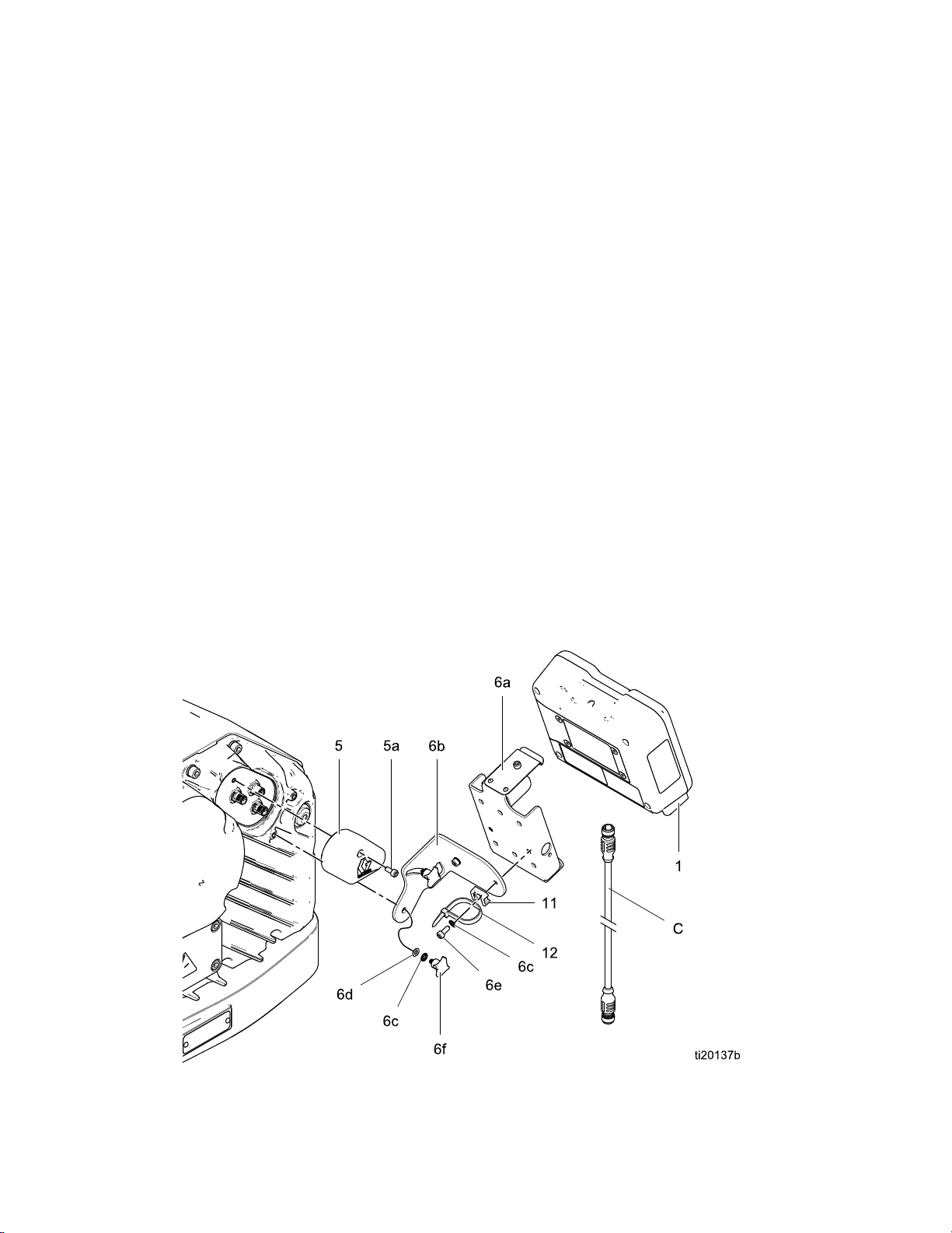
3.Assemblethebracketkit(6a-6f)andtheholder
andtie(11,12)asshown.
4.Installthemodule(1)inthebracket(6a),making
surethetabsatthebottomofthebracketengage
theslotsinthemodule,andthelipatthetopof
thebracketholdsthemodulesecurelyinplace.
5.Connecttheaccessorycable(C),usingthe
tie(12)asastrainreliefasshown.See
CableConnection,page5.
6.Restorepowertothemotor.
NOTE:
NOTE: NOTE:
differentmulti-unittopologies.
SeeAppendixCforinformationabout
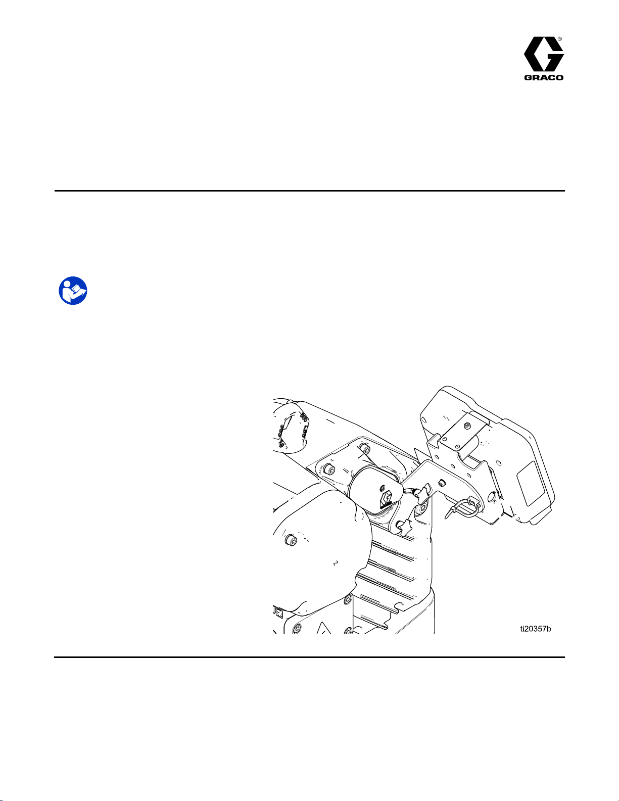
Figure1InstalltheControlModule(SinglePhaseModelShown)
4
3A2527L
Page 5
Installation
Cable
Cable Cable
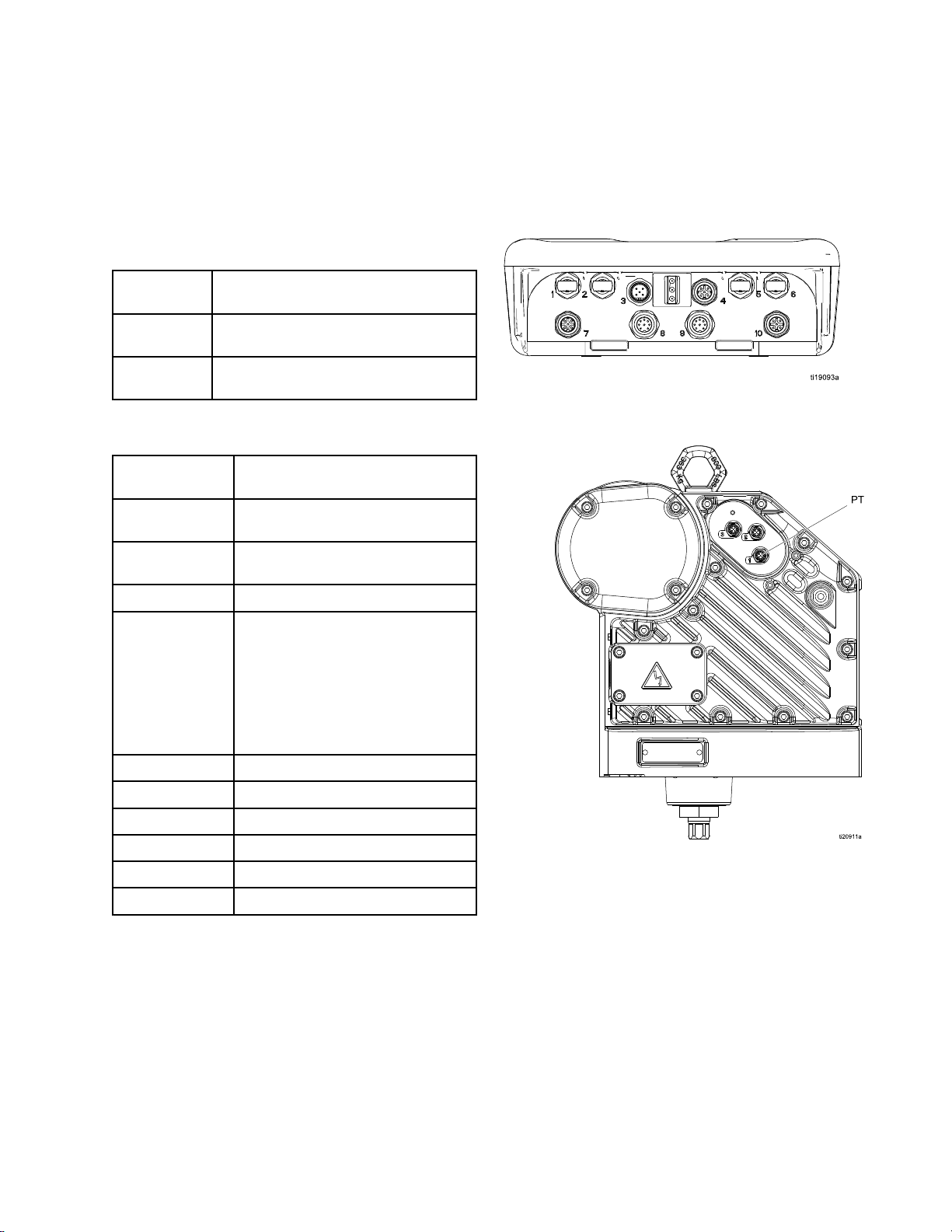
Orderanaccessorycable(C)fromTable1.ConnectthecabletoPort3onthebottomofthecontrolmodule
(seeFig.2).Connecttheotherendtothepowerterminal(PT)onthemotor(seeFig.3).Connectother
cablesasdescribedinTable2.
Table
Table Table
Cable
Cable Cable
No.
No. No.
16P911
16P912
Table
Table Table
ADCM
ADCM ADCM
Number
Number Number
1
2
Connection
Connection Connection
CAN
1 11CAN CAN
2 22ADCM ADCM
Cables
Cables Cables
Part
Part Part
ADCM
Port
Port Port
Description
Description Description
IntrinsicallysafeCANcable,female
xfemale,3ft(1m)
IntrinsicallysafeCANcable,female
xfemale,25ft(8m)
Cable
Connections
Cable Cable
Connections Connections
Connector
Connector Connector
FiberOpticRX-toFiberOptic
ConverterModule
FiberOpticTX-toFiberOptic
ConverterModule
Purpose
Purpose Purpose
Figure2ADCMConnectors
3
4
5
6
7
8BPRcontrol4-20mAoutput
9PrimaryTankLevelMonitor
10Pressuretransducer2
PowerandCANcommunication
•Start/Stopinput(pin2)
•Fillpumpoutput(pin3)
•Reedswitchinput(pin4)
•Agitatorhaltinput(pin4)
•Tankhighoutput(pin4)
•Tanklowoutput(pin4)
•Auxiliaryoutput(pin4)
FiberOpticRX-tonextADCM
FiberOpticTX-tonextADCM
Pressuretransducer1
Figure3MotorPowerTerminal
3A2527L 5
Page 6
Operation
Operation
Operation Operation
Module
Module Module
TheControlModulehastwosetsofscreens:
RunandSetup.Fordetailedinformationsee
RunScreens,page9,andSetupScreens,page13.
PresstotogglebetweentheRunscreensand
theSetupscreens.
InformationdisplayedontheRunandSteup
screenscorrespondstotheModbusRegisters.See
AppendixA-ModbusVariableMap,page34.
NOTE:
NOTE: NOTE:
loadrequirements.
Module
Module Module
Figure4isaviewofthecontrolmoduledisplayand
keys.Table2explainsthefunctionofthemembrane
keysonthecontrolmodule.Asyoumovethrough
thescreens,youwillnoticethatmostinformation
iscommunicatedusingiconsratherthanwords
tosimplifyglobalcommunication.Thedetailed
screendescriptionsinRunScreens,page9,and
SetupScreens,page13,explainwhateachicon
Screens
Screens Screens
Thescreenautomaticallydimsbasedonthe
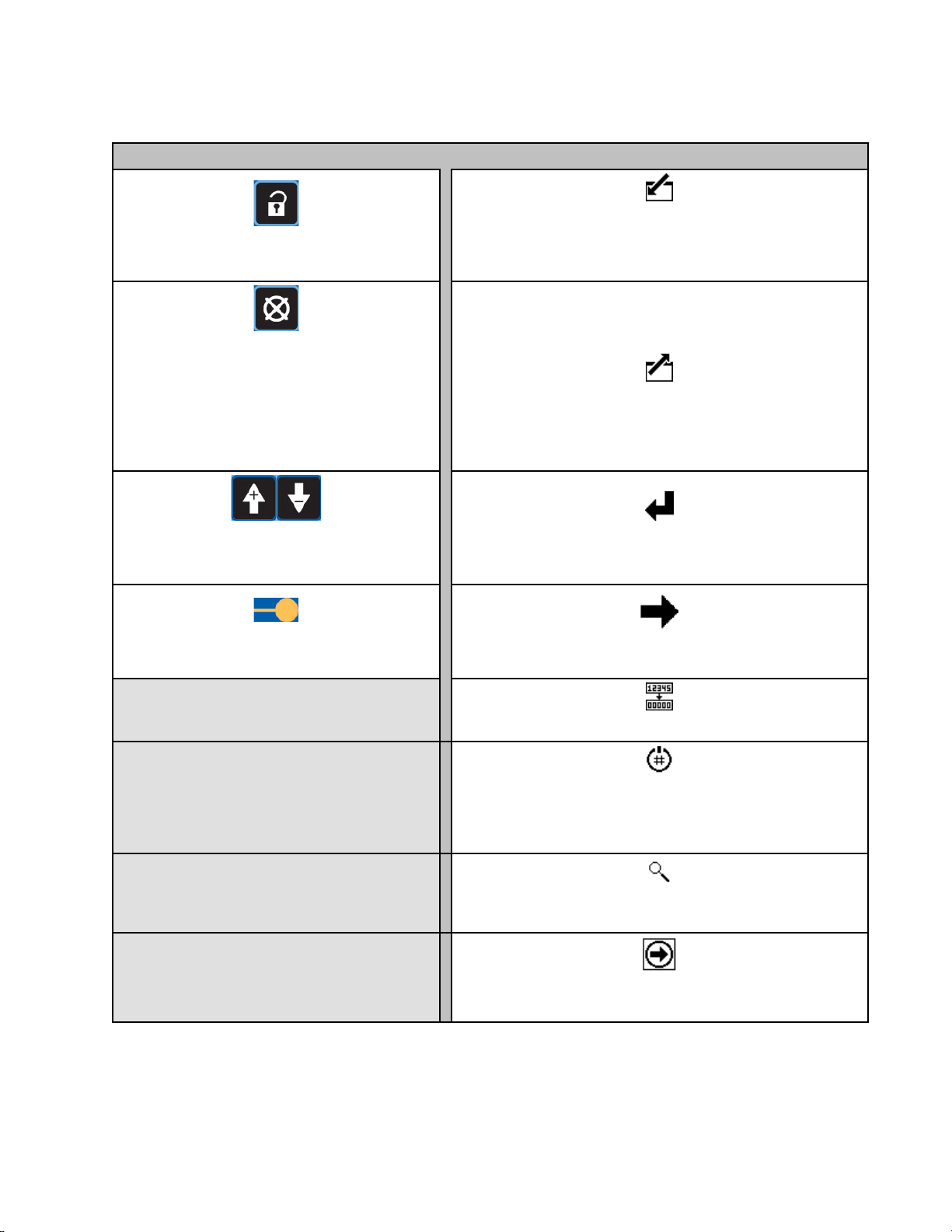
Keys
Keys Keys
represents.Thetwosoftkeysaremembranebuttons
whosefunctioncorrelateswiththescreencontentto
theimmediateleftofthebutton.
NOTICE
NOTICE NOTICE
Topreventdamagetothesoftkeybuttons,donot
pressthebuttonswithsharpobjectssuchaspens,
plasticcards,orngernails.
Figure4ControlModuleKeypadandDisplay
6 3A2527L
Page 7
Operation
Table
Table Table
alarmtoclear,thiskeysetstheactivepump’s
eldsonascreen,ortoincreaseordecrease
thenumericvaluesinaeldthatcanbeedited.
Module
3 33Module Module
Toggle:
Toggle: Toggle:
Cancel/Error
Cancel/Error Cancel/Error
thecausehasbeenxed.Whenthereisno
proletoStop.Alsousedtocancelthedata
enteredandreturntotheoriginaldata.
NOTE:
NOTE: NOTE:
disabledinSetupScreen16.
Up/Down
Up/Down Up/Down
Keys
Keys Keys
Membrane
Membrane Membrane
TogglebetweentheRunscreens
andSetupscreens.
Reset:
Reset: Reset:
Thepumpstopfunctioncanbe
Arrows:
Arrows: Arrows:
Movebetweenscreensor
Keys
Keys Keys
Clearthealarmafter
Softkeys
Softkeys Softkeys
Enter
Screen:
Enter Enter
Screen: Screen:
AlsochangesthefunctionoftheUp/Downarrows
sotheymovebetweendataeldsonthescreen,
Enter:
Enter: Enter:
Presstoactivateaeldforeditingortoaccept
thehighlightedselectiononamenu.
Highlightdatathatcanbeedited.
ratherthanbetweenscreens.
Exit
Screen:
Exit Exit
Screen: Screen:
Exitdataediting.
Softkeys:
Softkeys: Softkeys:
Softkeyscolumnsatright.
Variesbyscreen.Seethe
Right:
Right: Right:
Movetotherightwheneditingnumberelds.Press
againtoaccepttheentrywhenalldigitsarecorrect.
Reset:
Reset: Reset:
Activate
Activate Activate
andonlyappearsonSetupScreens1–4iftheProle Prole
Lock
Lock Lock
Search:
Search: Search:
Acknowledge:
Acknowledge: Acknowledge:
Prole:
Prole: Prole:
boxischeckedonSetupScreen25,page24.
Presstoactivatetheprolejustedited.
PressinRunScreen1tomaketheactive
Resettotalizertozero.
Thissoftkeyisdisabledbydefault,
pumpblinkforidentication.
Presstoacknowledgethatasoftware
updatehasconcluded.
Prole
3A2527L
7
Page 8
Operation
Screen
Screen Screen
Refertothissectionforinstructionsonnavigating
screens,enteringinformation,andmakingselections.
All
Screens
All All
Screens Screens
•Usetheupanddownarrowkeystomove
betweenscreens.
•Presstheenterscreenkey
Therstdataeldonthescreenishighlighted.
•Usethearrowkeys
thatyouwanttochange.
•Presstheenterkey
•Pressthecancelkey
•Whenalldataiscorrect,presstheexitscreen
key
downarrowkeys
screen,orthetoggleicon
SetupscreensandRunscreens.
Menu
Menu Menu
Navigation
Navigation Navigation
toexitthescreen.Thenusetheupand
Fields
Fields Fields
and
and and
toedit.
tocancel.
tomovetoanew
tohighlightthedata
Editing
Editing Editing
tomovebetween
toenterascreen.
Check
Check Check
Acheckboxeldisusedtoenableordisablefeatures
inthesoftware.
•Presstheenterkey
•Thefeatureisenabledifacheck
Reset
Reset Reset
Thereseteldisusedfortotalizers.Pressthe
totalizerresetkey
Initial
Initial Initial
NOTE:
NOTE: NOTE:
Screens1through4,youmustsetupthesystem
parametersinSetupScreens5through25,as
follows.
1.Pressthelockicon
2.ScrolltoSetupScreen5.
Box
Fields
Box Box
Fields Fields
totogglebetweenacheck
andanemptybox.
Field
Field Field
toresettheeldtozero.
Setup
Setup Setup
BeforecreatingthepumpprolesinSetup
toentertheSetup
screens.SetupScreen1appears.
isinthebox.
•Usetheupanddownarrowkeys
highlightthecorrectchoicefromthemenu.
•Presstheentericon
Number
Number Number
•Therstdigitintheeldishighlighted.Usethe
•Presstherightarrowkey
•Whenalldigitsarecorrect,presstherightarrow
Fields
Fields Fields
upanddownarrowkeys
number.
digit.
key
againtoaccept.
toselect.
tochangethe
tomovetothenext
to
3.SeeSetupScreen5,page16,andselectthe
lowerusedinyoursystem.
4.Continuesettingthesystemparameters
onSetupScreen6,page16through
SetupScreen25,page24.
5.ScrolltoSetupScreen1.Establish
theprolesforeachpump.See
SetupScreen1,page13through
SetupScreen4,page15.
8 3A2527L
Page 9
RunScreens
Run
Run Run
TheRunscreensdisplaycurrenttargetvaluesand
performanceforaselectedpumpandprole.Any
alarmsdisplayinthesidebarattherightofthe
screen.Screens7–10and11–14displayalogofthe
last20alarmsfortheactivepump.
TheactivepumpandprolemaybechangedinRun
Screens1,2,and3.
Screens
Screens Screens
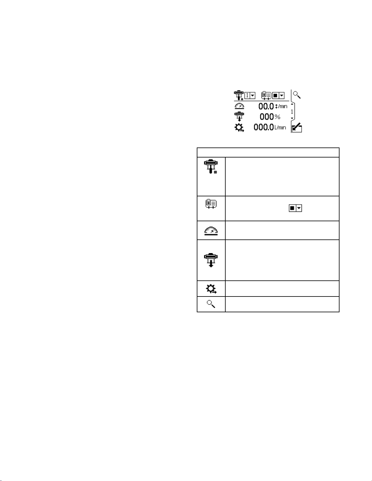
Run
Run Run
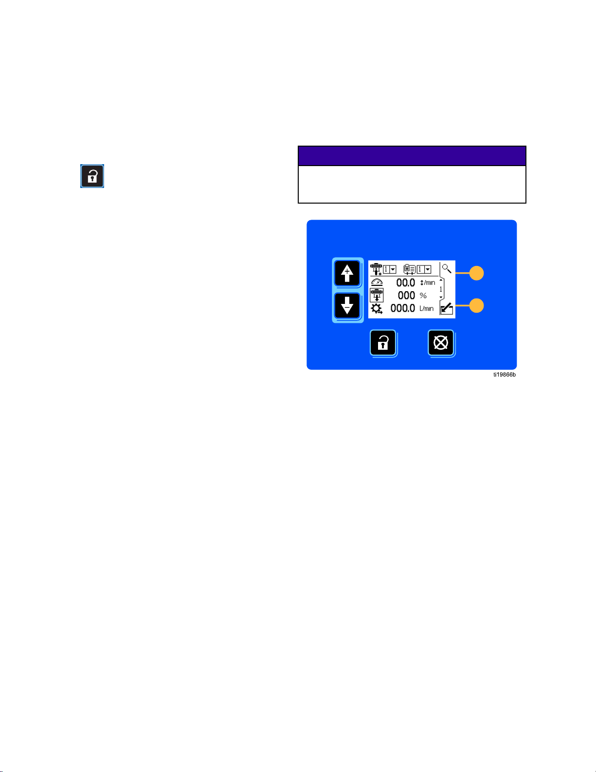
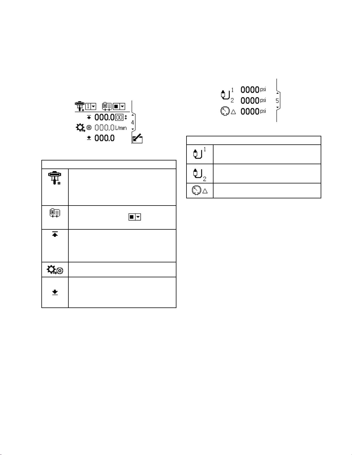
Thisscreendisplaysinformationforaselected
pumpandprole.Aboxaroundaniconindicates
whichmodetheactivepumpandproleisrunning
(pressureorow).
Figure5RunScreen1
Screen
Screen Screen
1
1 1
Run
Screen
Run Run
Screen Screen
Forsystemswithmultiplepumpsand
onedisplay,selectthepump(1to8)
fromthemenu.
NOTE:
NOTE: NOTE:
supportmultiplepumps.
Selecttheprole(1to4)fromthemenu.
Selectthestopoption
menutostopthepump.
Displaysthecurrentpumpspeedin
cyclesperminute.
Threephasesystemsdonot
Key
1 11Key Key
fromthe
Displaysthecurrentpumppressureas
apercentage.Ifatransducerisused,
thisiconisreplacedbythepressure
icon.Tosetupapressuretransducer,
seeSetupScreen8,page17and
SetupScreen9,page17.
Displayscurrentowrateinunitsas
selectedinSetupScreen18,page21.
Signalstheactivepumptoblinkcode9
foridentication.
3A2527L 9
Page 10
RunScreens
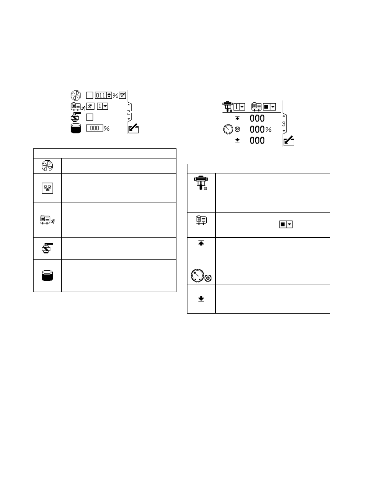
Run
Run Run
Thisscreendisplaysinformationforcontrollingan
electricagitatorusingthesupervisortopasson
thecontrolsetpointtoaVariableFrequencyDrive
(VFD),alsoknownasaninverter.
Figure6RunScreen2
Screen
Screen Screen
2
2 2
Run
Screen
Run Run
Screen Screen
Selectthisboxandsetthespeed
setpointfortheagitatorfrom0–100%.
Selectthisboxtoputagitator
controlinlocalonlymode.Setpoint
andEnable/Disablerequestsfrom
PLC/Supervisorwillbeignored.
Selectthisboxandholdthesoftkeyto
manuallyrunthepumpintheselected
prole.Thisfeatureallowstheuserto
runthemotorpastthetanklevellow
alarmtoemptythetank.
Selectthisboxandholdthesoftkey
buttontomanuallycontrolthellpump
solenoidoutput.
Currentprimarytankvolumeinpercent.
Theeldispopulatedwithdataonly
whenthetanksensorisenabled.See
SetupScreen19,page21.
Key
2 22Key Key
Run
Run Run
Thisscreendisplayspressuresettingsfortheactive
pumpandprole.Pressurecanbemeasuredinpsi,
bar,andMPa.
NOTE:
NOTE: NOTE:
setupselections.
Figure7RunScreen3,ShowninPressureMode
Screen
Screen Screen
Someeldsaregrayedout,dependingon
3
3 3
Run
Screen
Run Run
Screen Screen
Forsystemswithmultiplepumpsand
onedisplay,selectthepump(1to8)
fromthemenu.
NOTE:
NOTE: NOTE:
supportmultiplepumps.
Selecttheprole(1to4)fromthemenu.
Selectthestopoption
menutostopthepump.
Displaysthemaximumuidpressureas
selectedinSetupScreen2,page14.
SeeSetupScreen4,page15tosetor
disablethepressurealarms.
Displaysthetargetpressureasselected
inSetupScreen2,page14.
Displaystheminimumuidpressureas
selectedinSetupScreen2,page14.
SeeSetupScreen4,page15tosetor
disablethepressurealarms.
Threephasesystemsdonot
Key
3 33Key Key
fromthe
10 3A2527L
Page 11
RunScreens
Run
Run Run
Thisscreendisplaysuidowsettingsfortheactive
pumpandprole.Fluidowcanbemeasuresinliters
perminute,gallonsperminute,ccperminute,ozper
minute,orcyclesperminute.
NOTE:
NOTE: NOTE:
setupselections.
Figure8RunScreen4,ShowninPressureMode
Screen
Screen Screen
Someeldsaregrayedout,dependingon
4
4 4
Run
Screen
Run Run
Screen Screen
Forsystemswithmultiplepumpsand
onedisplay,selectthepump(1to8)
fromthemenu.
NOTE:
NOTE: NOTE:
supportmultiplepumps.
Selecttheprole(1to4)fromthemenu.
Selectthestopoption
menutostopthepump.
Displaysthemaximumowrateand
maximumcyclerateasselected
inSetupScreen3,page14.See
SetupScreen4,page15tosetor
disabletheowalarms.
Displaysthetargetowrateasselected
inSetupScreen3,page14.
Displaystheminimumowrateas
selectedinSetupScreen3,page14.
Threephasesystemsdonot
Key
4 44Key Key
fromthe
Run
Run Run
Thisscreendisplaysthecurrentpressurereadingsof
transducers1and2.Pressurecanbedisplayedas
psi,bar,orMPa.SeeSetupScreen23,page23.
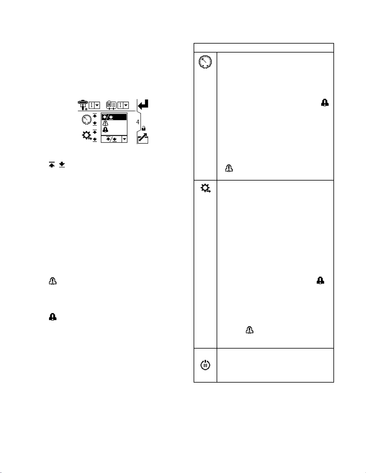
Figure9RunScreen5
Screen
Screen Screen
5
5 5
Run
Screen
Run Run
Screen Screen
Displaysthepressureoftransducer1.
Displaysthepressureoftransducer2.
Displaysthepressuredifference
betweentransducer1andtransducer2.
Key
5 55Key Key
SeeSetupScreen4,page15tosetor
disabletheowalarms.
3A2527L
11
Page 12
RunScreens
Run
Run Run
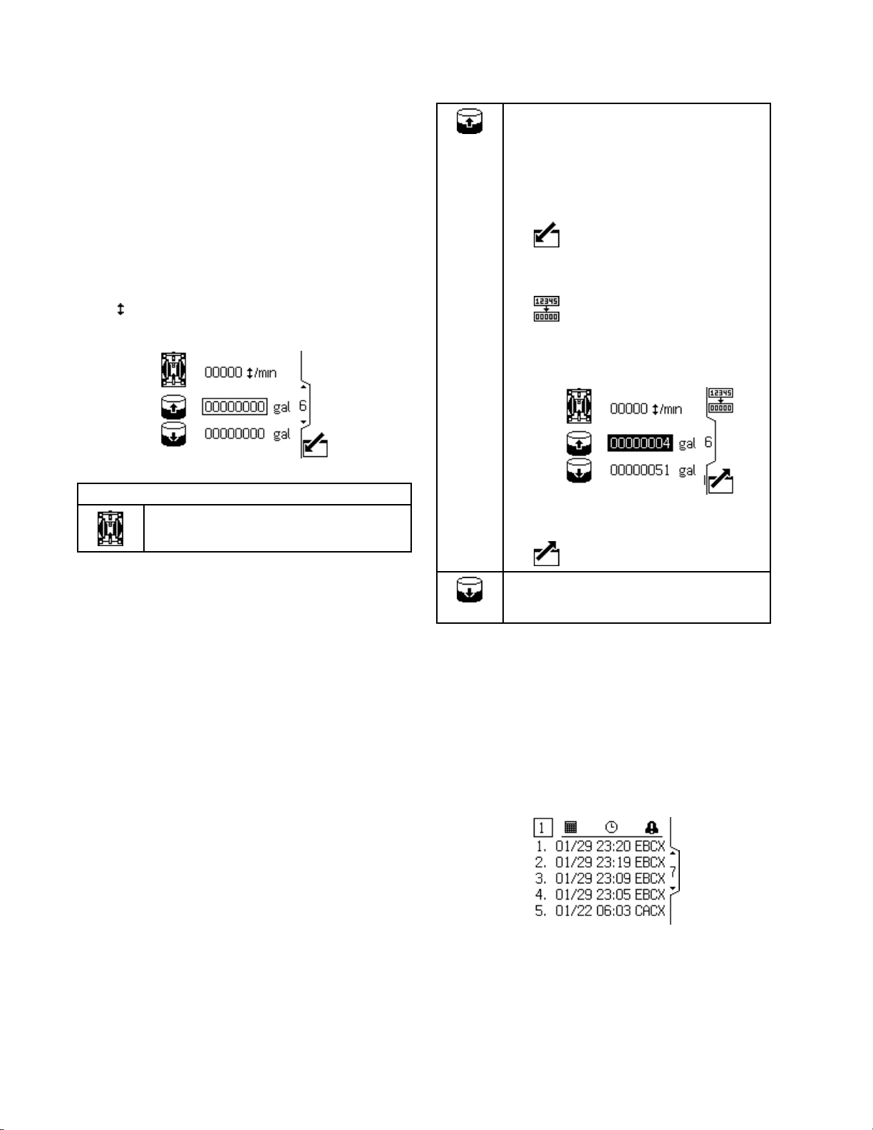
Thisscreendisplaysvolumeinformationaboutthe
tank:thevolumedispensedandtheremaining
volume.Thevolumecanbedisplayedaslitersor
gallons.SeeSetupScreen25,page24.
NOTES:
NOTES: NOTES:
•Thescreennumbermaydiffer,dependingonthe
•Thisscreenappearsonlywhentheauxiliaryinput
Figure10RunScreen6
Screen
Screen Screen
featuresthatareenabled.
isconguredforthereedswitchonSetupScreen
19:
SeeSetupScreen19,page21.
6
6 6
Run
Screen
Run Run
Screen Screen
Displaysthecurrentcyclerate.
6 66Key Key
Key
Displaysanestimateofthevolume
dispensedoutofthistanksincethelast
resetevent.
Toresetthevolumedispensed:
1.Pressthebottomrightsoftkeyto
enterthescreen:
2.Pressthetoprightsoftkeytoreset
thevolumedispensedto0:
Thevolumeremainingsetstothe
volumeenteredonSetupScreen16.
(SeeSetupScreen16,page19.)
3.Pressthebottomrightsoftkeytoexit
thescreen:
Displaysanestimateoftheremaining
volumeinthesecondarytank,basedon
thelastresetevent.
Run
Run Run
RunScreens7–10displayalogofthelast20alarms,
withdateandtime.
Thecurrentlyactivepumpisdisplayedinaboxat
thetopleftofthescreen.
Forerrorcodes,see
ErrorCodeTroubleshooting,page25.
Figure11RunScreen7
Screens
Screens Screens
7–10
7–10 7–10
12
3A2527L
Page 13
SetupScreens
Setup
Setup Setup
UsetheSetupscreensforpumpsettingsandaccessoryfeatures.See
ScreenNavigationandEditing,page8forinformationonhowtomakeselectionsandenterdata.
Inactiveeldsaregrayedoutonascreen.
NOTE:
NOTE: NOTE:
1–4,performtheinitialsetuponSetupScreens5–25
Setup
Setup Setup
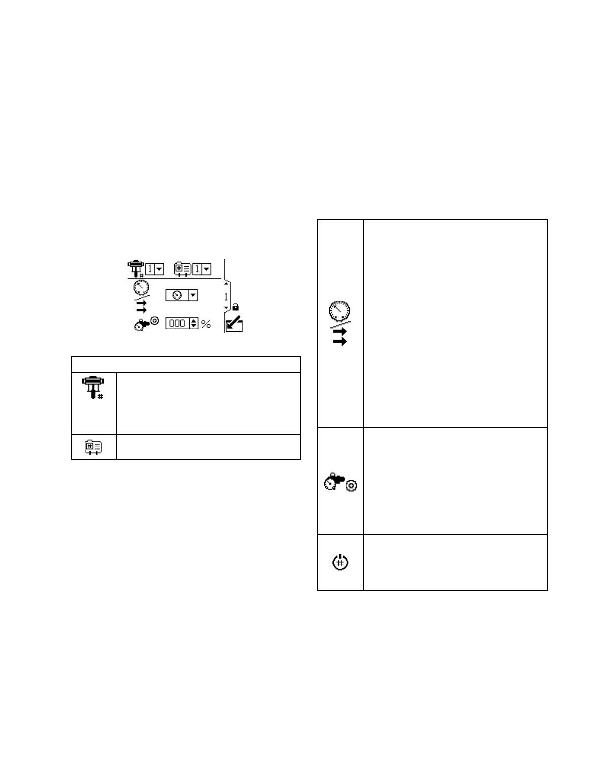
Usethisscreentosettheoperatingmodefora
selectedpumpandprole.
Figure12SetupScreen1
Screens
Screens Screens
BeforesettingupprolesonSetupScreens
Screen
Screen Screen
Forsystemswithmultiplepumpsand
onedisplay,selectthepump(1to8)
fromthemenu.
NOTE:
NOTE: NOTE:
supportmultiplepumps.
Selecttheprole(1to4)fromthemenu.
1
1 1
Setup
Setup Setup
Screen
Screen Screen
Threephasesystemsdonot
Key
1 11Key Key
toestablishthecongurationforyoursystemand
affectthedisplayeddata.
Selecttheoperatingmode
(force/pressureorow)fromthe
menu.
•Inforce/pressuremode,themotor
adjuststhepumpspeedtomaintain
theuidpressurepercentageseton
SetupScreen2.Iftheowlimitis
reachedbeforethetargetpressure,
theunitstopsdrivingtothepressure
(ifsetasanalarm).
•Inowmode,themotormaintains
aconstantspeedtomaintainthe
targetowratesetonSetupScreen
3,regardlessoftheuidpressure,
uptothepump’smaximumworking
pressure.
NOTE:
NOTE: NOTE:
onthreephasemotorsystems.
Ifthesystemisequippedwithaback
pressureregulator(BPR),setthetarget
airpressuretotheBPRfrom0to100
percent(approximately1to100psi).
Leavetheeldsetto000forasystem
withnoBPR.Thisvaluerepresentsthe
percentagethatisclosedontheBPR.If
thevalueisgreaterthanzerobutthere
isnoBPRsystem,theL6CAerrorcode
appears.
Thissoftkeyisdisabledbydefault,and
onlyappearsiftheProle Prole
checkedonSetupScreen25,page24.
Presstoactivatetheprolethatyoujust
edited.
Thisselectionisonlyavailable
Prole
Lock
Lock Lock
boxis
3A2527L 13
Page 14
SetupScreens
Setup
Setup Setup
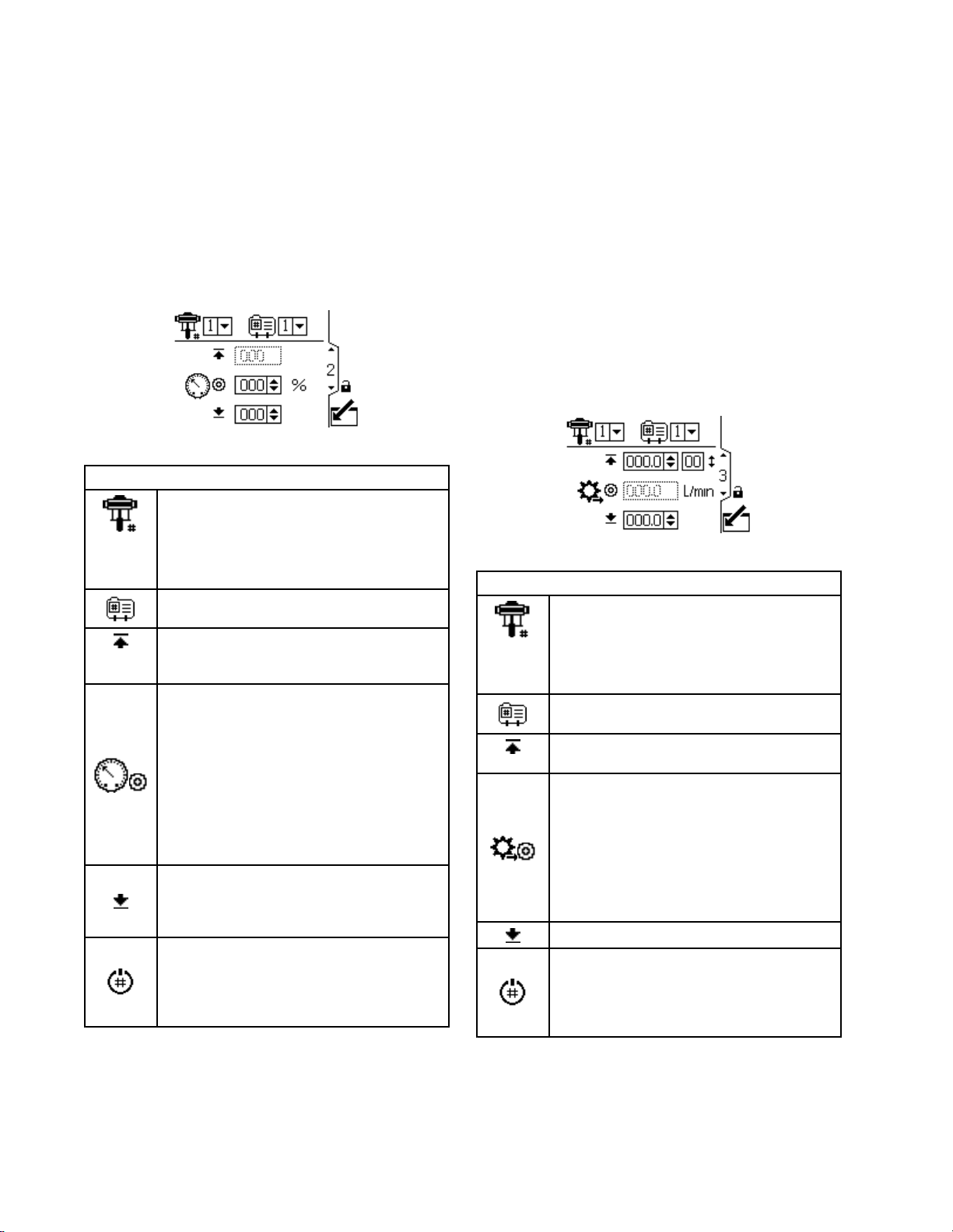
Usethisscreentosetthemaximum,target,and
minimumforce/uidpressureforaselectedpump
andprole.Inforce/pressuremode,youcanset
atargetforce/uidpressure.Inowmode,you
cansetamaximumforce/uidpressure.Ineither
force/pressureorowmode,youcansetaminimum
pressure.SeeSetupScreen4,page15,tospecify
howthesystemwillrespondifthepumpbeginsto
operateoutsideofthesetboundaries.
Figure13SetupScreen2
Screen
Screen Screen
Forsystemswithmultiplepumpsand
onedisplay,selectthepump(1to8)
fromthemenu.
NOTE:
NOTE: NOTE:
supportmultiplepumps.
Selecttheprole(1to4)fromthemenu.
Setthemaximumpumpuid
force/pressure,asapercentageof
themaximumpressureofyourpump.
Inforce/pressuremode,settheforce/uid
pressuretargetasapercentageofthe
maximumpressureofyourpump.This
eldisnotusedinowmode.
NOTE:
NOTE: NOTE:
enabled,thetargetpressureisdisplayed
asapressurevalue(psi,bar,MPa)rather
thanapercentageofmaximumpressure.
SeeSetupScreen8,page17toenable
closedlooppressurecontrol.
Optionally,setaminimumpump
force/uidpressure,asapercentageof
themaximumforce/uidpressureofyour
pump.
Thissoftkeyisdisabledbydefault,and
onlyappearsiftheProle Prole
checkedonSetupScreen25,page24.
Presstoactivatetheprolethatyoujust
edited.
2
2 2
Setup
Setup Setup
Screen
Screen Screen
Threephasesystemsdonot
Ifclosedlooppressureis
Key
2 22Key Key
Prole
Lock
Lock Lock
boxis
Setup
Setup Setup
Usethisscreentosetyourowratesettingsfora
selectedpumpandprole.Inpressuremode,you
willsetamaximumowrate.Inowmode,youwill
setatargetowrate.Ineitherpressureorowmode,
aminimumowratemaybeset.SeeSetupScreen
4tospecifyhowthesystemwillrespondifthepump
beginstooperateoutsideofthesetboundaries.
NOTE:
NOTE: NOTE:
valuethatcanbedisplayedis9999.Iftheeld
displays####,thesavedvalueisoutofrange.Go
toSetupScreen18,page21andchangetheow
ratetoalargerunit.Returntothisscreenandreduce
thesettingtoalowervaluethatwillbewithinthe
display’srange,thenresettheowrateunitsto
cc/min.
Figure14SetupScreen3
Screen
Screen Screen
Withowrateunitsofcc/min,themaximum
Forsystemswithmultiplepumpsand
onedisplay,selectthepump(1to8)
fromthemenu.
NOTE:
NOTE: NOTE:
supportmultiplepumps.
Selecttheprole(1to4)fromthemenu.
Inowmode,setatargetowrate.This
eldisnotusedinpressuremode.
Inpressuremode,setthemaximumow
rate.Thesoftwarecalculatesthenumber
ofpumpcyclesneededtoachievethat
owrate.Thiseldisnotusedinow
mode.
NOTE:
NOTE: NOTE:
maximumowratesetting,themotorwill
notrunanderrorcodeWSC_appears.
Optionally,setaminimumowrate.
Thissoftkeyisdisabledbydefault,and
onlyappearsiftheProle Prole
checkedonSetupScreen25,page24.
Presstoactivatetheprolethatyoujust
edited.
3
3 3
Setup
Setup Setup
Screen
Screen Screen
Threephasesystemsdonot
Iftheproledoesnothavea
Key
3 33Key Key
Prole
Lock
Lock Lock
boxis
14
3A2527L
Page 15
SetupScreens
Setup
Setup Setup
Usethisscreentospecifyhowthesystemresponds
ifthepumpbeginstooperateoutsideofthepressure
andowsettingsestablishedonSetupScreen2and
SetupScreen3.Theoperatingmode(pressureor
ow,setonSetupScreen1)determineswhichelds
areactive.
Figure15AlarmPreferenceMenu
•/Limit: Limit:
noalert.
–MaximumpressuresettoLimit:Thesystem
–MaximumowsettoLimit:Thesystemreduces
–MinimumpressureorowsettoLimit:The
–PressurelimiterrorsincludeP1I_,P2I_,P3I_,
–FlowrateerrorsincludeK1D_,K2D_,K3D_,and
•
problem,butthepumpmaycontinuetorunpast
themaximumorminimumsettingsforveseconds
untilthesystem’sabsolutepressureorow
boundariesarereached.
•
causeandshutsdownthepump.
NOTE:
NOTE: NOTE:
activemeasurementsarefromtheirsetlimits.
Screen
Screen Screen
Limit:
reducestheowifnecessarytopreventthe
pressurefromexceedingthelimit.
thepressureifnecessarytopreventtheow
fromexceedingthelimit.
systemtakesnoaction.Usethissettingforno
minimumpressureorowsetting.
andP4I_.
K4D_.
Deviation:
Deviation: Deviation:
Alarm:
Alarm: Alarm:
Thesystemalertsyoutothealarm
Alerttriggertimevariesbasedonhowfar
4
4 4
Thepumpcontinuestorunandissues
Thesystemalertsyoutothe
Setup
Setup Setup
Toenablethepressurealarm:
•Line1(PressureMaximum):Select
Limit
Limit Limit
Forrunawaycontrol,setthemaximum
owtoAlarm Alarm
themaximumenteredonSetupScreen
3forveseconds,analarmsymbol
appearsonthescreenandthepump
shutsdown.
•Line2(PressureMinimum):Select
Limit
Limit Limit
Todetectapluggedlterorpipe,setthe
minimumowtoDeviation Deviation
ratedropsbelowtheminimumentered
onSetupScreen3,adeviationsymbol
appearsonthescreentowarnyouto
takeaction.Thepumpcontinuestorun.
Toenabletheowratealarm:
•Line3(FlowMaximum):SelectLimit Limit
Deviation
Deviation Deviation
Topreventtheconnectedequipment
fromexcessivepressure,setthe
maximumpressuretoLimit.
•Line4(FlowMinimum):SelectLimit Limit
Deviation
Deviation Deviation
Forrunawaycontrol,settheminimum
pressuretoAlarm Alarm
pumpdoesnotchangespeed,butthe
backpressurefalls.Whenthepressure
fallsbelowtheminimumenteredon
SetupScreen2,anAlarmsymbol
appearsonthescreenandthepump
shutsdown.
Todetectapluggedlterorpipe,setthe
maximumpressuretoDeviation Deviation
thepressureexceedsthemaximum
enteredonSetupScreen2,aDeviation
symbol
warnyoutotakeaction.Thepump
continuestorun.
Thissoftkeyisdisabledbydefault,and
onlyappearsiftheProle Prole
checkedonSetupScreen23,page23.
Presstoactivatetheprolethatyoujust
edited.
Screen
Screen Screen
Deviation
,Deviation Deviation
Alarm
Deviation
,Deviation Deviation
,orAlarm Alarm
.Iftheowrateexceeds
,orAlarm Alarm
Deviation
Alarm
,orAlarm Alarm
Alarm
,orAlarm Alarm
Alarm
.Ifahosebursts,the
appearsonthescreento
Prole
Key
4 44Key Key
Alarm
.
Alarm
.
.Iftheow
Limit
.
Limit
.
Deviation
Lock
Lock Lock
.When
boxis
,
,
3A2527L 15
Page 16
SetupScreens
Setup
Setup Setup
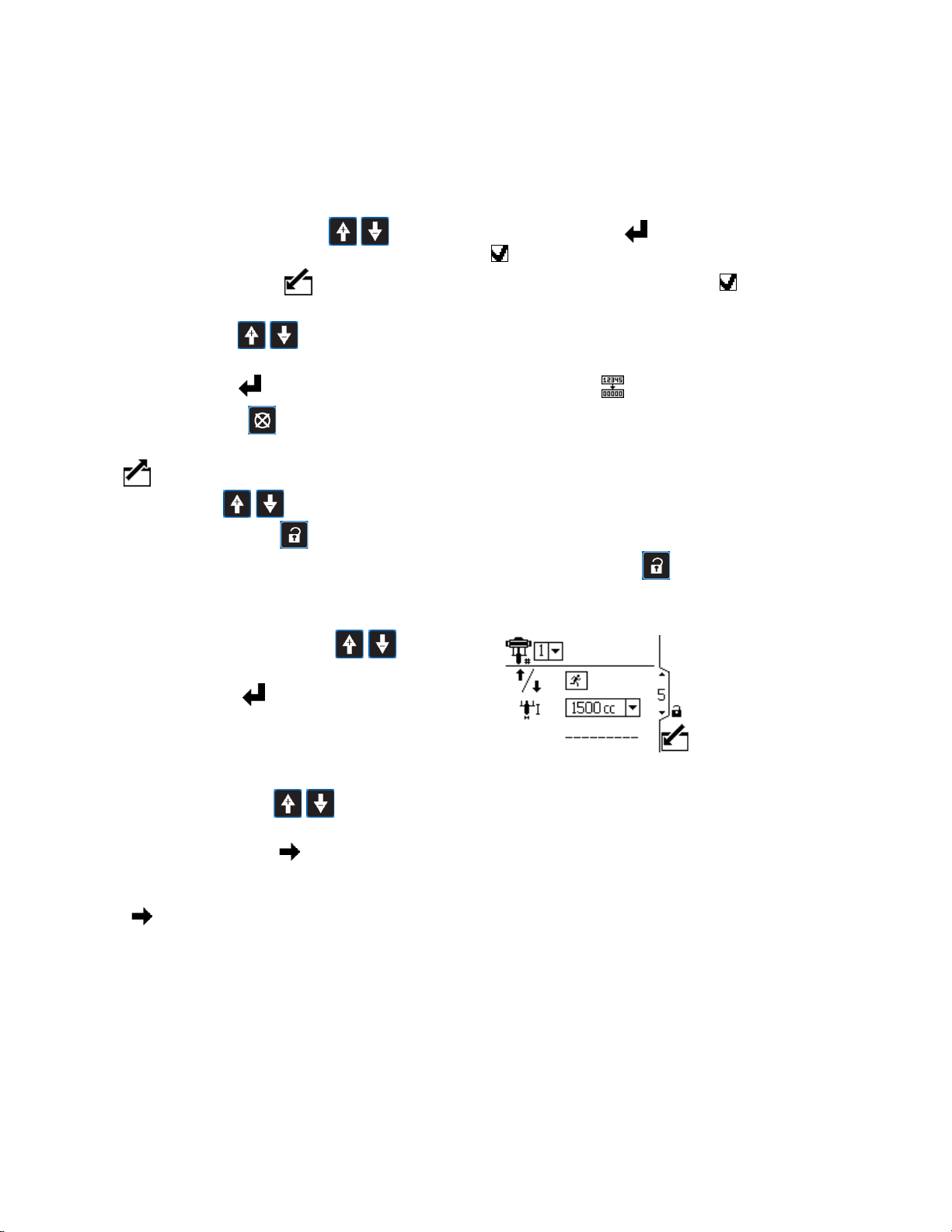
Usethisscreentosetthelowerpumpsize(cc)of
eachpump.Thedefaultisblank;selectthecorrect
lowersize,orcustom.Ifcustomisselected,enterthe
sizeofthelowerincc.Thisscreenalsoactivatesjog
mode,allowingyoutopositionthemotor/pumpshaft
forconnectionordisconnection.
NOTE:
NOTE: NOTE:
theselectedloweris750cc,topreventexceedingthe
pressureratingofthelower.
Figure16SetupScreen5
Screen
Screen Screen
Themotorwilllimititspressureoutputwhen
5
5 5
Setup
Setup Setup
Forsystemswithmultiplepumpsand
onedisplay,selectthepump(1to8)
fromthemenu.
NOTE:
NOTE: NOTE:
supportmultiplepumps.
Selecttoenablejogmode.Usethe
arrowkeystomovethemotoror
pumpshaftupordown.
Selectthecorrectpumplowersize
fromthemenu.Thedefaultisblank.
Ifcustomisselected,aeldopens
foryoutoinputthesizeofthelower
incc.
•Supplypumps
Screen
Screen Screen
Threephasesystemsdonot
Key
5 55Key Key
Setup
Setup Setup
Usethisscreentoviewthegrandtotalizervalueand
tosetorresetthebatchtotalizer.
Figure17SetupScreen6
Setup
Setup Setup
Usethisscreentosetthemaintenanceinterval(in
cycles)foreachpump.Thescreenalsodisplaysthe
currentcyclecount.ErrorcodeMND_appearswhen
thecounterreaches0(zero).
Screen
Screen Screen
Forsystemswithmultiplepumpsand
onedisplay,selectthepump(1to8)
fromthemenu.
NOTE:
NOTE: NOTE:
supportmultiplepumps.
Displaysthecurrentgrandtotalofpump
cycles.Thiseldcannotbereset.
Displaysthebatchtotalinselected
volumeunits.
Resetsthebatchtotalizertozero.
Screen
Screen Screen
6
6 6
Setup
Setup Setup
Screen
Screen Screen
Threephasesystemsdonot
7
7 7
Key
6 66Key Key
–145cc
–180cc
–220cc
–290cc
•Circpumps
–750cc*
–1000cc
–1500cc
–2000cc
–2500cc
*When750ccisselected,the
maximumforceiscappedto75%
topreventoverpressurizingthe
pump.
16 3A2527L
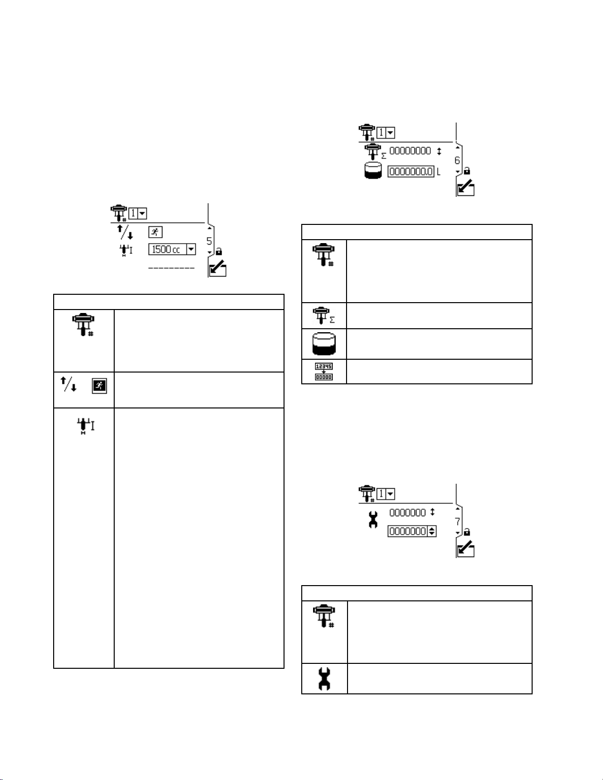
Figure18SetupScreen7
Setup
Setup Setup
Forsystemswithmultiplepumpsand
onedisplay,selectthepump(1to8)
fromthemenu.
NOTE:
NOTE: NOTE:
supportmultiplepumps.
Setthemaintenanceinterval(incycles)
foreachpump.
Threephasesystemsdonot
Screen
Screen Screen
7 77Key Key
Key
Page 17
SetupScreens
Setup
Setup Setup
Usethisscreentosetupthepressurefor
transducer1.Selectingatransducerandapump
activatesclosedlooppressurecontrol.
NOTE:
NOTE: NOTE:
transducertobeinstallednearthepumpoutlet.
Figure19SetupScreen8
Screen
Screen Screen
Closedlooppressurecontrolrequiresthe
Selectfromthemenuoptions(500psior
5000psi)toenablethetransducer.
Thisoptionenablesclosedlooppressure
controlandassignsthetransducertoa
pump.
•Forsystemswithmultiplepumpsand
onedisplay,selectthepump(1to8)
fromthemenu.
•Forthreephasepumps,selectpump
1.
Enterthecalibrationscalefactorfromthe
transducerlabel.
8
8 8
Setup
Setup Setup
Screen
Screen Screen
Key
8 88Key Key
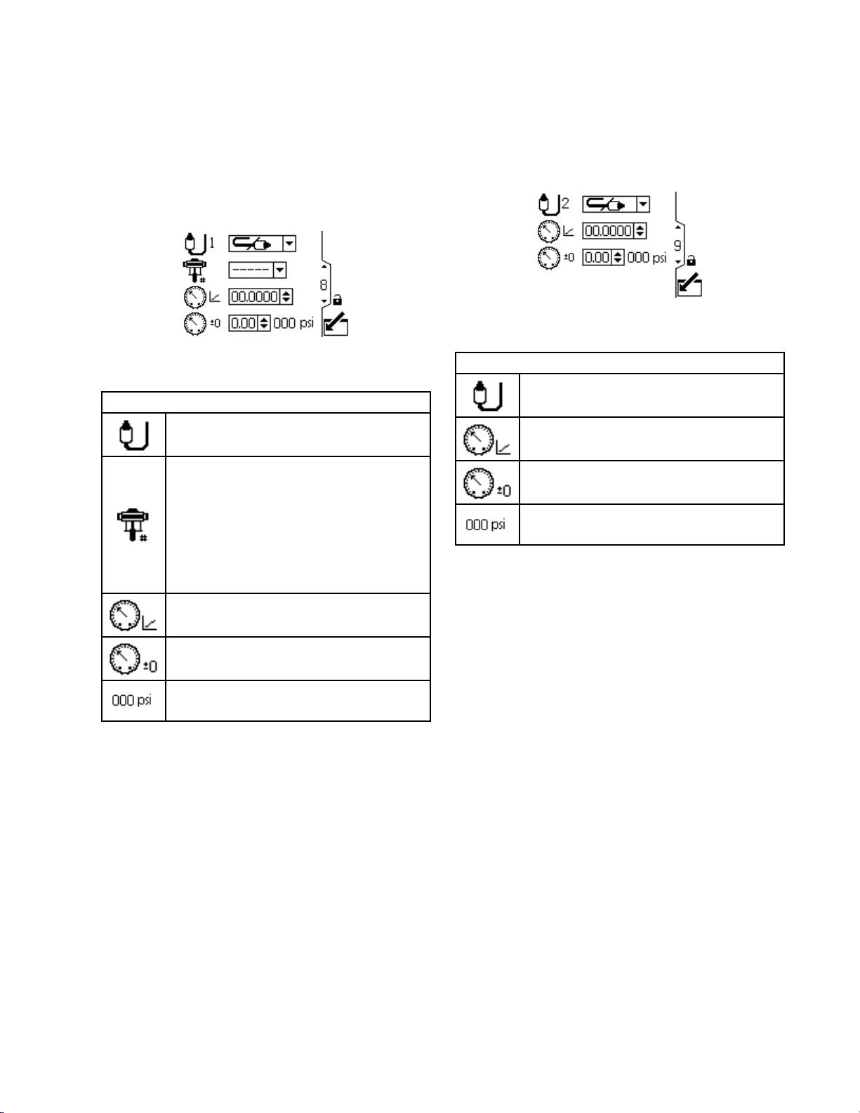
Setup
Setup Setup
Usethisscreentosetupthepressurefortransducer
2.ThetypicalapplicationismonitoringBPRuid
pressure.
Figure20SetupScreen9
Screen
Screen Screen
Selectfromthemenuoptions(500psior
5000psi)toenablethetransducer.
Enterthecalibrationscalefactorfromthe
transducerlabel.
Enterthecalibrationoffsetvaluefromthe
transducerlabel.
Displaysthecurrenttransducerreading.
9
9 9
Setup
Setup Setup
Screen
Screen Screen
Key
9 99Key Key
Enterthecalibrationoffsetvaluefromthe
transducerlabel.
Displaysthecurrenttransducerreading.
3A2527L
17
Page 18

SetupScreens
Setup
Setup Setup
Usethisscreentospecifyhowthesystemresponds
ifthesystempressurebeginstooperateoutsideof
thesystemsettings.
Pressuretransducer2monitorsthepressureatthe
BPR.
Deltapressuremonitorsthedifferencebetweenthe
pumpoutletandtheBPR.
Figure21SetupScreen10
Thefollowingeventscanappear:
•
issuesnoalert.
•Deviation: Deviation:
theproblem,butthepumpmaycontinuetorun
pastthemaximumorminimumsettingsforve
secondsuntilthesystem’sabsolutepressureor
owboundariesarereached.
•
causeandshutsdownthepump.
Screen
Screen Screen
No
event:
No No
event: event:
Deviation:
Alarm:
Alarm: Alarm:
Thesystemalertsyoutothealarm
10
10 10
Thepumpcontinuestorunand
Thesystemalertstheuserto
Setup
Setup Setup
Thesescreensareauto-populatedbythesoftware.
Screen11displaystheserialnumbersofmotors1–4,
andScreen12displaystheserialnumbersofmotors
5–8.
NOTES:
NOTES: NOTES:
•Thescreennumbersmaydiffer,dependingonthe
featuresthatareenabled.
•Changingthepumporderwillshifteveryother
pumpuponeposition.Forexample,ifAD00001
ischangedtobepump4,AD00002willbecome
pump1,AD00003willbecomepump2,andsoon.
Figure22SetupScreens11and12(Screen11
shown)
Setup
Setup Setup
Thesescreensareauto-populatedbythesoftware.
Screen13displaysthesoftwareversionnumbers
ofmotors1–4,andScreen14displaysthesoftware
versionnumbersofmotors5–8.
Screens
Screens Screens
Screens
Screens Screens
11
and
11 11
13
13 13
12
and and
12 12
and
14
and and
14 14
NOTE:
Setup
Setup Setup
Screen
Screen Screen
10
Key
10 10
Key Key
Maximumandminimum
pressure.
Canbeconguredasno
event,deviation,oralarm.
Pressuredifference
betweentransducer1
and2.
NOTE: NOTE:
onthefeaturesthatareenabled.
Figure23SetupScreens13and14(Screen13
shown)
Thescreennumbersmaydiffer,depending
18 3A2527L
Page 19

SetupScreens
Setup
Setup Setup
Usethisscreentosetyourmodbuspreferences.
NOTES:
NOTES: NOTES:
•Thescreennumbermaydiffer,dependingonthe
featuresthatareenabled.
•Thefollowingarexedmodbussettings,which
cannotbesetorchangedbytheuser:DataBits:
8,StopBits:2,Parity:None
Figure24SetupScreen15
Screen
Screen Screen
Forsystemswithmultiplepumpsand
onedisplay,selectthepump(1to8)
fromthemenu.
NOTE:
NOTE: NOTE:
supportmultiplepumps.
Selectlocalorremotefrom
themenu.Thissettingappliestothe
selectedpumponly.
Localmodeallowsyoutoviewchanges
overthemodbusnetwork,butyoucannot
makechangesoverthemodbusnetwork.
Remotemodeallowsyoutobothview
andchangeinformationoverthemodbus
network.
EnterorchangetheModbusnodeID.
Thevalueisbetween1and246.Each
pumprequiresauniquenodeID,which
identiesthatpumpifmorethanone
pumpisconnectedtothedisplay.
Selecttheserialportbaudratefromthe
menu.Thisisasystem-widesetting.
15
15 15
Setup
Setup Setup
Screen
Screen Screen
Threephasesystemsdonot
15
15 15
Key
Key Key
Setup
Setup Setup
Usethisscreentocongureandcontrolthetankll
featureandIntelligentPaintKitchenperipherals.
NOTES:
NOTES: NOTES:
•Thescreennumbermaydiffer,dependingonthe
featuresthatareenabled.
•Thealerttriggertimevariesbasedonhowfar
activemeasurementsarefromtheirsetlimits.
Figure25SetupScreen16
Screen
Screen Screen
Selectthisboxtomanuallyactivatethe
llsolenoidoutputonport4,pin3.
Selectthisboxtoenablethetankto
automaticallyll.Youcanthensetthe
lllevels.
Congurethelowllpumpow
noticationforadeviationoranalarm
andsetthetime-outvalueinseconds.
Ifa1%levelchangeisnotdetected
withthetimeoutperiodinseconds,the
systemtakesactionbasedontheevent
type.
16
16 16
Setup
Setup Setup
Screen
Screen Screen
Whenthetanklevelreachesthis
level,thellsolenoidturnsoff.
Thisvaluecannotbehigherthan
thelevelbelow.
Whenthetanklevelreachesthis
level,thellsolenoidturnson.
Thisvaluecannotbelowerthan
thelevelabove.
16
Key
16 16
Key Key
•38400kbps
•57600kbps(default)
•115200kbps
3A2527L 19
Page 20

SetupScreens
Setup
Setup Setup
Usethisscreentomonitor,setup,andcontroltheIntelligentPaintKitchenperipherals.Formoreinformation,
seetheSetUpPeripheralssectionoftheIntelligentPaintKitchenmanual3A4030.
NOTES:
NOTES: NOTES:
•Thescreennumbermaydiffer,dependingonthefeaturesthatareenabled.
•Thesecondeldvaries,dependingonthemenuselectioninthersteld.
Figure26SetupScreen17,ReedSwitchOption
Shown
Screen
Screen Screen
Selecttheconnectedperipheralfromthemenu.
17
17 17
ConguresPort4pin4asaninputtoallowareedswitchtobeconnected.
Thecurrentreedswitchcyclerateappearsnexttothecyclerateicon
perminute.
Figure27SetupScreen17,ManualControlOption
Shown
Setup
Setup Setup
Screen
Screen Screen
17
Key
17 17
Key Key
incycles
ConguresPort4pin4asaninputtoallowapressureswitchtobeconnected.Ifthe
drumcoverisliftedwhilethiscongurationisproperlyconnected,theagitatorshutsdown.
Thecurrentinputstatusappearsintheagitatorstatuseld
NOTE:
NOTE: NOTE:
ConguresPort4pin4asanoutputtoallowfortheconnecteddevicetoreceiveanalarm
whenthelevelofthePrimaryTankisabovethevaluethatisdenedinthePrimary
TankHigheld.
ThisvalueisapercentageofthetotallevelofthePrimaryTank.
ConguresPort4pin4asanoutputtoallowfortheconnecteddevicetoreceiveanalarm
whenthelevelofthePrimaryTankisbelowthevaluethatisdenedinthePrimary
TankLoweld
ThisvalueisapercentageofthetotallevelofthePrimaryTank
ConguresPort4pin4asanoutputtoallowforanothersolenoidtobeconnectedand
controlledfromthedevice.
Selectthemanualoutputbox
solenoidmanually.Afteryoureleasethebutton,themanualactivationisterminated.
TheExternalTankFilloptionconguresPort4pin4asanoutputthesameastheone
ASupervisorModuleisrequiredforthisfunction.
.
andholdthebuttontocontroltheauxiliary
.
above.ThisoptionalsotiestheTankHighAlarm
outputsuchthattheADCMleavesitaloneforexternalcontroluntilthetanklevelgoes
abovethesetpoint.Afterthetanklevelisabovethesetpoint,theoutputisforcedoff.
,asconguredbelow,tothis
20 3A2527L
Page 21

SetupScreens
TheTankHighAlarmallowsfortheconnecteddevicetoreceiveanalarmwhenthelevelofthe
primarytankisabovethevaluethatisdenedinthiseld.Ifthevalueissetto0,theeventis
disabled.
TheTankLowAlarmallowsfortheconnecteddevicetoreceiveanalarmwhenthelevelofthe
primarytankisbelowthevaluethatisdenedinthiseld.Ifthevalueissetto0,theeventis
disabled.
Aneventcanbeconguredasadeviationoranalarm.Intheeventofanalarm,thepumpshutsoff
andtheagitatorturnsoff.
Setup
Setup Setup
Usethisscreentosetthestrokedisplacement
volumeandowrateunitsofthellpumpthatis
connectedtothecycleswitchinput.
NOTE:
NOTE: NOTE:
auxiliaryinputisselectedonSetupScreen17.See
SetupScreen17,page20.
Figure28SetupScreen18
Screen
Screen Screen
Thisscreenisgrayedoutunlessthe
Thestrokedisplacement:enterthe
volumepercycleincubiccentimeters.
Selecttheowrateunitstodisplayon
therunscreen:
•cycles/min
•cc/min
•liters/min
•gallons/min
18
18 18
Setup
Setup Setup
Screen
Screen Screen
18
Key
18 18
Key Key
Setup
Setup Setup
Usethisscreentocongurethefullvolumeofthe
secondarytank,andthepointsatwhichtheuseris
notiedthatthetankisnearingemptyandempty.
NOTE:
NOTE: NOTE:
auxiliaryinputisselectedonSetupScreen17.See
SetupScreen17,page20.
Figure29SetupScreen19
Screen
Screen Screen
Thisscreenisgrayedoutunlessthe
Enterthefulluidvolumeofthe
secondarytank.
Entertheuidvolumeatwhichpointthe
userisnotiedthatthesecondarytankis
nearingempty.
Whenthecurrentvolumeislessthanor
equaltothisvalue,thesystemgenerates
anL2B0event.
Entertheuidvolumeatwhichpointthe
userisnotiedthatthesecondarytank
isempty.
19
19 19
Setup
Setup Setup
Screen
Screen Screen
19
Key
19 19
Key Key
Whenthecurrentvolumeislessthanor
equaltothisvalue,thesystemgenerates
anL1B0event.
3A2527L
21
Page 22

SetupScreens
Setup
Setup Setup
Usethisscreentosetuptheinputscaling(radarlevel
sensor)for4–20mAdevicesandturnonthecurrent
loop(Port8andPort9oftheADCM).
NOTE:
NOTE: NOTE:
thefeaturesthatareenabled.
Figure30SetupScreen20
Screen
Screen Screen
Thescreennumbermaydiffer,dependingon
MonitorthebackpressureregulatormA
output.
SetthevalueforP9(Port9)between4
and20.
Selectthisboxtoturnonthe4-20mA
supply.Setthenumericalvaluesforthe
scalingceilingfor4-20mAsignal.
Setthetankleakagesetpoint.When
thepumpisputintooffproduction,the
systemcapturesthecurrenttanklevel.
If,atanytime,thecurrenttanklevel
dropsbythepercentageindicatedhere,
aleakagealarmwilltriggerandstop
thepump.Ifthevalueissetto0%,the
leakagealarmisdisabled.
20
20 20
Setup
Setup Setup
Screen
Screen Screen
20
Key
20 20
Key Key
Setup
Setup Setup
Thisscreenisforenablingamodbuscommunications
alarmanddisablingtheStopPumpfunctionofthe
Cancelkey.
NOTE:
NOTE: NOTE:
thefeaturesthatareenabled.
Figure31SetupScreen21
Screen
Screen Screen
Thescreennumbermaydiffer,dependingon
Selectthemodbusalarmtype:
SelectthisboxtomakeCAN
communicationadeviationthat
doesnotshutdownthepump.
SelectthisboxtodisabletheStopPump
functionoftheReset/Cancelkey.
Enableordisablethebacklightandset
thetime-outvalueinminutes.
21
21 21
Setup
Screen
Setup Setup
Screen Screen
None
Deviation
Alarm
21
Key
21 21
Key Key
SeeSetupScreen22,page23.
22
3A2527L
Page 23

SetupScreens
Setup
Setup Setup
Usethisscreentoenableordisabletherun/stop
switchandautorestart.
NOTE:
NOTE: NOTE:
thefeaturesthatareenabled.
Figure32SetupScreen22
Screen
Screen Screen
Thescreennumbermaydiffer,dependingon
Enableordisabletherun/stopswitch.The
defaultsettingisdisabled.SeeRun/Stop
SwitchKitinAccessories,page31.
Whenenabled,thiscongurationallows
therun/stopswitchtopausethepump
whileinaprole.Whentherun/stopswitch
isactive,thefollowingpop-upappears:
22
22 22
Setup
Setup Setup
Screen
Screen Screen
22
22 22
Enableordisableautorestart.Thedefault
settingisdisabled.Ifenabled,theunit
resumesoperationattheprolethatwas
setbeforetheunitwasturnedoff.
Enabletheoffproductionprolemode.
Thisfeatureturnsprole4intotheoff
productionprole.Whenprole4isactive,
thellpumpisdisabledandthecurrent
primarytanklevelisrecorded.Ifthe
primarytankleveldropsmorethanthe
congurableleakagelevelpercentage,the
systemtriggersthealarmandshutsoffthe
pump.
Thetankleakagesetpointis
conguredinSetupScreen20.(See
Key
Key Key
Setup
Setup Setup
Usethisscreentosettheunitsforpressure,totals,
andow.
SetupScreen20,page22.)
Screen
Screen Screen
23
23 23
Disabletheremotestartfunctionover
modbus.
Whenenabledalongwiththerun/stop
switch,youmusttoggletherun/stopswitch
whengoingfromprole0(stopped)to
runbeforethepumpcanstart.Whenthe
run/stopswitchisactive,thefollowing
pop-upappears:
Figure33SetupScreen23
Setup
Setup Setup
Selectthepressureunits:
•psi
•bar(default)
•MPa
Selectthevolumeunits:
•liters(default)
•gallons
•cc
Selecttheowrateunits:
•L/min(default)
•gpm
•cc/min
•oz/min
•cycles/min
Selectthesystemmode(singleorx2).
Ifyouareinsinglemodebutconnected
tox2orinx2modebutconnectedto
single,errorcodeWNNXappears.
Screen
Screen Screen
23
Key
23 23
Key Key
3A2527L 23
Page 24

SetupScreens
Setup
Setup Setup
Usethisscreentosetyourdateformat,date,time,
orforcearestartofthesystemwhenupdatingthe
software(updatetokeninsertedintothedisplay).
Afterthesoftwareupdateiscompletedsuccessfully,
thetokenmustberemovedpriortoselectingthe
Acknowledgekeyorpowercyclingthedisplay.Ifan
updatewasconcludedandthetokenisnotremoved,
pressingtheAcknowledgekeyrestartstheupdate
process.
NOTES:
NOTES: NOTES:
•Thescreennumbermaydiffer,dependingonthe
featuresthatareenabled.
•RefertoAppendixC-ControlModule
Programming,page54forinstructionsonsoftware
updating.Softwareupdateisdisruptivetoall
pumpsconnectedtothedisplay.Allpumps
attachedtothedisplaymustnotbepumping
materialwhenthesoftwareupdateisinitiated.
Screen
Screen Screen
24
24 24
Setup
Setup Setup
Usethisscreentoenterapasswordthatwillbe
requiredtoaccesstheSetupscreens.Thisscreen
alsodisplaysthesoftwareversion.
NOTE:
NOTE: NOTE:
thefeaturesthatareenabled.
Figure35SetupScreen25
Screen
Screen Screen
Thescreennumbermaydiffer,dependingon
Enterthe4–digitpassword.
Checktheboxtolockouttheagitator
eldintheRunscreens.
Checktheboxtolockouttheproleeld
ontheRunscreens.
25
25 25
Setup
Screen
Setup Setup
Screen Screen
25
Key
25 25
Key Key
Figure34SetupScreen24
Setup
Setup Setup
Selectyourpreferreddateformatfrom
themenu.
•MM/DD/YY
•DD/MM/YY(default)
•YY/MM/DD
Setthecorrectdate.
Setthecorrecttime.
Performasoftrestartofthesystem.
Screen
Screen Screen
24
Key
24 24
Key Key
24
3A2527L
Page 25

ErrorCodeTroubleshooting
Error
Error Error
Errorcodescantakethreeforms:
•Alarm:alertsyoutothealarmcauseandshuts
downthepump.
•Deviation
maycontinuetorunpastthesetlimitsuntilthe
system’sabsolutelimitsarereached.
•Advisory:informationonly.Pumpwillcontinue
tooperate.
Display
Display Display
Code
Code Code
NoneBasic6Alarm
Code
Code Code
:alertsyoutotheproblem,butpump
Applicable
Applicable Applicable
Motor
Motor Motor
Troubleshooting
Troubleshooting Troubleshooting
Blink
Blink Blink
Code
Code Code
Alarm
Alarm Alarm
Deviation
Deviation Deviation
Notes
about
Notes Notes
about about
•OnAdvancedmotors,ow(Kcodes)andpressure
(Pcodes)canbedesignatedasalarmsor
deviations.SeeSetupScreen4,page15.
•“X”meansthecodeisassociatedwiththedisplay
only.
•“_”inthecodeisaplaceholderforthenumberof
thepumpwheretheeventoccurred.
•Theblinkcodeisdisplayedusingthepower
indicatoronthemotor.Theblinkcodegivenbelow
indicatesthesequence.Forexample,blinkcode
1–2indicates1blink,then2blinks;thesequence
thenrepeats.
•Ablinkcodeof9isnotanerrorcode,butan
indicatorofwhichpumpisactive(
beenpushed,seeRunScreen1,page9).
or
or or
TheModeSelectknobissetbetweenPressure
.Settheknobtothemodeyouwant.
the
following
the the
following following
Description
Description Description
error
codes:
error error
codes: codes:
softkeyhas
andFlow
None
A4N_
A4N_ A4N_
A5N_
A5N_ A5N_
CAC_
CAC_ CAC_
CAD_
CAD_ CAD_
C3G_
C3G_ C3G_
C4G_
C4G_ C4G_
CBN_
CBN_ CBN_
CCC_
CCC_ CCC_
CCN_
CCN_ CCN_
Basicand
Advanced
Basicand
Advanced
Basicand
Advanced
AdvancedNoneAlarm
Advanced2–3Alarm
AdvancedNoneDeviation
AdvancedNoneAlarm
Basicand
Advanced
Advanced3–7Alarm
Basicand
Advanced
9None
6Alarm
4–6Alarm
2–4Deviation
3–6Alarm
Ablinkcodeof9isnotanerrorcode,butanindicatorof
whichpumpisactive.
Themotorcurrentexceeded13Aorthehardwareovercurrent
trippedat20A.
Internalhardwarecurrentcalibration.Replaceelectronics.
NOTE:
NOTE: NOTE:
DisplaydetectsalossofCANcommunication.Flashing
alarmappearsonthedisplay,andtheblinkcodeoccurs.
UnitdetectsalossofCANcommunication.Thisalarmisonly
logged.Noashingalarmappearsonthedisplay,butthe
blinkcodedoesoccur.
Displaydetectsalossofmodbuscommunicationwhen
modbusdeviationisenabledonSetupScreen16.
Displaydetectsalossofmodbuscommunicationwhen
modbusalarmisenabledonSetupScreen16.
Temporarycircuitboardcommunicationfailure.
Nodisplaywasdetectedatstartup.
NOTE:
NOTE: NOTE:
Circuitboardcommunicationfailure.
3phasemotoronly.
3phasemotoronly.
END_
END_ END_
3A2527L 25
Basicand
Advanced
5–6Advisory
Acalibrationoftheencoderandstrokerangeisinprogress.
Page 26

ErrorCodeTroubleshooting
Alarm
Display
Display Display
Code
Code Code
Applicable
Applicable Applicable
Motor
Motor Motor
Blink
Blink Blink
Code
Code Code
Alarm Alarm
Deviation
Deviation Deviation
or
or or
Description
Description Description
ENDC
ENDC ENDC
ENN_
ENN_ ENN_
E5D_
E5D_ E5D_
E5F_
E5F_ E5F_
E5N_
E5N_ E5N_
E5S_
E5S_ E5S_
E5U_
E5U_ E5U_
EBC_
EBC_ EBC_
ELD_
ELD_ ELD_
ELI_
ELI_ ELI_
ERR_
ERR_ ERR_
F1F0
F1F0 F1F0
AdvancedNoneAdvisory
AdvancedNoneAdvisory
Basicand
Advanced
AdvancedNoneAdvisory
Basicand
Advanced
AdvancedNoneAdvisory
AdvancedNoneAdvisory
AdvancedNoneAdvisory
Basicand
Advanced
Basicand
Advanced
Basicand
Advanced
AdvancedNoneAlarm
1–7Deviation
2–7Deviation
4–7Advisory
4–5Deviation
2–5Deviation
Calibrationoftheencoderandstrokerangewassuccessfully
completed.
Duallowersystemcalibrationcompletedsuccessfully.
Calibrateencoderfailure.
Duallowersystemcalibrationerror.Systemrunningtoo
rapidlytoperformcalibration.
Calibratestrokefailed.
Duallowersystemcalibrationstoppedorinterrupted.
Duallowersystemcalibrationunsteady.Systemcouldnot
determineoptimumsetting.
Run/StopswitchinStopposition(closed).
Startupeventrecord.
Deviationhotboardreset.
Deviationsoftwareerror.
Fillpumpownotdetected.Theprimarytanklevelhasnot
increasedwiththenoowtimeoutwindowandthenoow
timeouteventissettoalarm.
Fillpumpownotdetected.Theprimarytanklevelhasnot
F2F0
F2F0 F2F0
K1D_
K1D_ K1D_
K2D_
K2D_ K2D_
K3D_
K3D_ K3D_
K4D_
K4D_ K4D_
L1A0
L1A0 L1A0
L1AF
L1AF L1AF
L1BX
L1BX L1BX
L2A0
L2A0 L2A0
AdvancedNoneDeviation
Advanced1–2Alarm
AdvancedNoneDeviation
AdvancedNoneDeviation
Basicand
Advanced
AdvancedNoneAlarm
AdvancedNoneAlarm
AdvancedNoneAlarm
AdvancedNoneDeviation
1Alarm
increasedwiththenoowtimeoutwindowandthenoow
timeouteventissettodeviation.
Flowisbelowminimumlimit.
Flowisbelowminimumlimit.
Flowexceedsmaximumtarget;alsoindicatespumprunaway
conditionexists.
Flowexceedsmaximumtarget;alsoindicatespumprunaway
conditionexists.
Primarytankcurrentlevelisbelowtheprimarytankalarm
setpoint.
Whilethesystemwasinoffproductionmode,thecurrent
tankleveldroppedbelowtheleakagealarmpercentage.
Theestimatedremainingvolumeinthesecondarytank
isbelowthealarmlevel.Thevalueiscalculatedastotal
tankvolumesubtractedfromllpumpcountercalculated
dispensedvolume.
Theprimarytankcurrentlevelisbelowtheprimarytank
deviationsetpoint.
26 3A2527L
Page 27

ErrorCodeTroubleshooting
Alarm
Display
Display Display
Code
Code Code
L2BX
L2BX L2BX
Applicable
Applicable Applicable
Motor
Motor Motor
AdvancedNoneDeviation
Blink
Blink Blink
Code
Code Code
Deviation
Deviation Deviation
or
Alarm Alarm
or or
Theestimatedremainingvolumeinthesecondarytankis
belowthedeviationlevel.Thevalueiscalculatedastotal
tankvolumesubtractedfromllpumpcountercalculated
dispensedvolume.
Description
Description Description
L3A0
L3A0 L3A0
L4A0
L4A0 L4A0
L6CA
L6CA L6CA
L6CB
L6CB L6CB
MND_
MND_ MND_
P1CB
P1CB P1CB
P1D_
P1D_ P1D_
P9D_
P9D_ P9D_
P1I_
P1I_ P1I_
P2I_
P2I_ P2I_
P2CB
P2CB P2CB
AdvancedNoneDeviation
AdvancedNoneAlarm
AdvancedNoneDeviation
AdvancedNoneDeviation
AdvancedNoneAdvisory
AdvancedNoneAlarm
AdvancedNoneDeviation
AdvancedNoneDeviation
Advanced1–3Alarm
AdvancedNoneDeviation
AdvancedNoneDeviation
Theprimarytankcurrentlevelisabovetheprimarytank
deviationsetpoint.
Theprimarytanklevelisabovetheprimarytanklevelhigh
alarmsetpoint.
Port8isenabledandthecurrentdrawislessthan4mA.
TheBPRisrequestingavaluegreaterthan0%.Verifythat
thedeviceisconnected.
Port9isenabledandthecurrentdrawislessthan4mA.
Verifythatthedeviceisconnected.
Maintenancecounterisenabledandcountdownreached
zero(0).
Pressuretransducer2pressureisbelowthealarmsetpoint.
Unbalancedload.DualLowersystem—P1D1=Motor1is
requiringlessforcetoholdspeed;pumplowermayneed
service.P1D2=Motor2isrequiringlessforcethanmotor
1toholdspeed.
Majorunbalancedload—seeP1D_(P9D_ishigher
magnitude)
Pressureisbelowminimumlimit.
Pressureisbelowminimumlimit.
Pressuretransducer2pressureisbelowthedeviationset
point.
P3CB
P3CB P3CB
P3I_
P3I_ P3I_
P4CB
P4CB P4CB
P4I_
P4I_ P4I_
P5DX
P5DX P5DX
P6CA
P6CA P6CA
P6CB
P6CB P6CB
P6D_
P6D_ P6D_
P7C_
P7C_ P7C_
P9C_
P9C_ P9C_
T2D_
T2D_ T2D_
3A2527L
AdvancedNoneDeviation
AdvancedNoneDeviation
AdvancedNoneAlarm
Advanced1–4Alarm
AdvancedNoneDeviation
or
AdvancedNoneDeviation
Advanced1–6Alarm
AdvancedNoneDeviation
AdvancedNoneAlarm
Basicand
Advanced
3–5Alarm
Pressuretransducer2pressureisabovethedeviationset
point.
Pressureexceedsmaximumtarget.
Pressuretransducer2pressureisabovethealarmsetpoint.
Pressureexceedsmaximumtarget.
Morethanonepumpisassignedtoatransducer.The
assignmentforthattransducerisautomaticallyclearedunder
thiscondition.Usermustreassign.
Forunitswithoutclosedlooppressurecontrol:Transducer
(AorB)isenabledbutnotdetected.
Forunitswithclosedlooppressurecontrol:Transduceris
enabledbutnotdetected.
Pressuredifferencebetweentransducer1andtransducer2
isgreaterthanthedeviationsetpoint.
Pressuredifferencebetweentransducer1andtransducer2
isgreaterthanthealarmsetpoint.
Internalthermistordisconnectedormotortemperatureis
below0°C(32°F).
27
Page 28

ErrorCodeTroubleshooting
Alarm
Display
Display Display
Code
Code Code
Applicable
Applicable Applicable
Motor
Motor Motor
Blink
Blink Blink
Code
Code Code
Alarm Alarm
Deviation
Deviation Deviation
or
or or
Description
Description Description
T3D_
T3D_ T3D_
T4D_
T4D_ T4D_
V1I_
V1I_ V1I_
V2I_
V2I_ V2I_
V1M_
V1M_ V1M_
V3I_
V3I_ V3I_
V4I_
V4I_ V4I_
V9M_
V9M_ V9M_
WCW_
WCW_ WCW_
WMC_
WMC_ WMC_
Basicand
Advanced
Basicand
Advanced
Basicand
Advanced
Basicand
Advanced
Basicand
Advanced
Basicand
Advanced
Basicand
Advanced
Basicand
Advanced
AdvancedNoneAlarm
Basicand
Advanced
4–6Alarm
NoneDeviation
2–6Alarm
NoneDeviation
4–5Alarm
5
2Alarm
3Alarm
7
Deviation
Alarm
Motorovertemperature.Motorwillthrottleitselftostaybelow
85°C(185°F)internally.
Motorovertemperature.Motorwillthrottleitselftostaybelow
85°C(185°F)internally.
Brownout;voltagesuppliedtomotoristoolow.
Brownout;voltagesuppliedtomotoristoolow.
ACpowerislost.
Voltagesuppliedtomotoristoohigh.
Voltagesuppliedtomotoristoohigh.
Lowsupplyvoltagedetectedatstartup.
Systemtypemismatch;motorisanE-FloDCduallower
systemandthedisplaycongurationdoesnotmatch.
Changethedisplay’ssystemtypeontheSetupUnitsscreen
(screen15).
Internalsoftwareerror.
WNC_
WNC_ WNC_
WNN_
WNN_ WNN_
WSC_
WSC_ WSC_
WSD_
WSD_ WSD_
WXD_
WXD_ WXD_
Basicand
Advanced
AdvancedNoneAlarm
AdvancedNoneDeviation
Advanced1–5Alarm
Basicand
Advanced
3–4Alarm
4Alarm
Softwareversionsdonotmatch.
Systemtypemismatch;motorisanE-FloDCsinglelower
systemandthedisplaycongurationdoesnotmatch.
Changethedisplay’ssystemtypeontheSetupUnitsscreen
(screen12induallowermode).
Proleissetto0pressureor0ow.
Invalidlowersize;occursiftheunitisoperatedbeforesetting
upthelowersize.
Aninternalcircuitboardhardwarefailureisdetected.
28 3A2527L
Page 29

Parts
Parts
Parts Parts
24P822
24P822 24P822
Ref
Ref Ref
124P821
1a▲16P265LABEL,warning,
1b▲16P265LABEL,warning,
1c▲16P265LABEL,warning,
5
5a
624P823
Part
Part Part
24N910
———
Control
Control Control
Module
Module Module
Description
Description Description
DISPLAYKIT,control
module;includes
item1a;seemanual
332013forapprovals
informationaboutthe
bareADCMmodule
English
French
Spanish(shipped
loose)
CONNECTOR,
jumper;includes
item5a
SCREW,cap,socket
head;M5x40mm
BRACKETKIT,
controlmodule;
includesitems6a-6f
Kit
Kit Kit
(Single
(Single (Single
Phase,
Phase, Phase,
Qty
Qty Qty
1
1
1
1
1
1
1
Side
Side Side
Ref
Ref Ref
6a
6b
6c
6d
6e
6f
11
12
▲ReplacementDangerandWarninglabels,tags,
andcardsareavailableatnocost.
Itemsmarked———arenotavailableseparately.
Cable(C)isshownforreferencebutisnotincluded
inthekit.Orderspeciedlengthseparately.See
CableConnection,page5.
Part
Part Part
———
———
———
———
———
———
———
———
Mount)
Mount) Mount)
Description
Description Description
BRACKET,control
module
BRACKET,mounting
LOCKWASHER,
externaltooth;M5
WASHER;M5
SCREW,cap,socket
head;M5x12mm
KNOB;M5x0.8
HOLDER,tie
STRAP,tie
Qty
Qty Qty
1
1
4
2
2
2
1
1
3A2527L 29
Page 30

Parts
17V232
17V232 17V232
Ref
Ref Ref
1
1a▲
1b▲16P265LABEL,warning,
624P823
6a*
6b
6c
Part
Part Part
———
———
———
———
———
Control
Control Control
Module
Module Module
Description
Description Description
DISPLAYKIT,control
module;includes
item1a;seemanual
332013forapprovals
informationaboutthe
bareADCMmodule
LABEL1
French
BRACKETKIT,
controlmodule;
includesitems6a-6f
BRACKET,control
module
BRACKET,mounting
LOCKWASHER,
externaltooth;M5
Kit
(Three
Kit Kit
(Three (Three
Phase,
Phase, Phase,
Qty
Qty Qty
1
1
1
1
1
4
Side
Side Side
Ref
Ref Ref
6d
6e
6f
11
12
17
▲ReplacementDangerandWarninglabels,tags,
andcardsareavailableatnocost.
Itemsmarked———arenotavailableseparately.
Cable(C)isshownforreferencebutisnotincluded
inthekit.Orderspeciedlengthseparately.See
CableConnection,page5.
Part
Part Part
———
———
———
———
———
———
Mount)
Mount) Mount)
Description
Description Description
WASHER;M5
SCREW,cap,socket
head;M5x12mm
KNOB;M5x0.8
STRAP,tiewiring
HOLDER,tie
TOKEN,GCA,
upgrade,E-FloDC
(notshown)
Qty
Qty Qty
2
2
2
1
1
1
17W754
17W754 17W754
30 3A2527L
Top
Mount
Top Top
Mount Mount
Bracket
Bracket Bracket
Kit
Kit Kit
Page 31

Accessories
Accessories
Accessories Accessories
NOTE:
NOTE: NOTE:
soldseparately.
Partsforkitsinthefollowingtablearenot
Part
Part Part
25D293
25D294
17S640AuxiliarySolenoidKit
24Z671TankFillKit
241405
24A032
17B160
17T898
Kit
Kit Kit
RadarSensorKit
ReedSwitchCounterKit
FiberOpticCablesKM172
FiberOpticCablesKM173
BPR
BPR BPR
Ref
Ref Ref
101
102
103110436
104100030
105198178
106110207
107
108198171
———
Controller
Controller Controller
Part
Part Part
———
———
C19466
Parts not sold separately.
Kit
24V001
Kit Kit
24V001 24V001
Description
Description Description
TRANSDUCER,
miniature
CABLE,F/C,I.S.,8M
GAUGE,pressure,air
BUSHING
ELBOW
ELBOW
TEE1
ELBOW
Qty
Qty Qty
1
1
1
1
1
1
1
3A2527L 31
Page 32

Accessories
Run/Stop
Run/Stop Run/Stop
Technical
Technical Technical
Switch
Switch Switch
Specications
Specications Specications
Kit
16U729
Kit Kit
16U729 16U729
for
16U729
for for
16U729 16U729
Run/Stop
Run/Stop Run/Stop
Switch
Switch Switch
Voltage
Current
Power240Wmaximum
AmbientTemperature
EX
EX EX
Classication"SimpleApparatus"inaccordancewithUL/EN/IEC
ParametersUi=17.9V
Switch
Switch Switch
Ratings:
Ratings: Ratings:
Ratings:
Ratings: Ratings:
Kit
16U729
Kit Kit
16U729 16U729
US
US US
24VDC
10A
–13°-122°F–25°-50°C
60079-11,clause5.7
ClassI,Div1:GroupDT4
II
1
II II
1 1
ExiaIIAT4Ga
Ii=217mA
Pi=937mW
Ci=1200pF
Metric
Metric Metric
G
G G
Li=6.8uH
Li/Ri=7.4uH/Ohm
32 3A2527L
Page 33

Accessories
Pressure
Pressure Pressure
2 22- --ball ball
Technical
Technical Technical
ball
Ref
Ref Ref
101ADAPTER,
102
103
———
pumps
pumps pumps
Description
Description Description
tting,
pressure
sensor
PACKING,
o-ring
SENSOR,
pressure,uid
outlet
Transducer
Transducer Transducer
Parts not sold separately.
Specications
Specications Specications
Kit
Kit Kit
24Y245
24Y245 24Y245
24R050
24R050 24R050
Part
Part Part
16U4401
1193481
16P28915M6691
for
for for
for
for for
24R050
24R050 24R050
ball
4 44- --ball ball
24Y245
24Y245 24Y245
Part
Part Part
pumps
pumps pumps
Qty
Qty Qty
and
24Y245
and and
24Y245 24Y245
24R050,
24R050, 24R050,
Pressure
Pressure Pressure
Transducer
Transducer Transducer
Kit
for
Kit Kit
for for
Pressure
Pressure Pressure
Electrical
Electrical Electrical
Voltage
FullScalesensitivity
SpanAtMaxpressure
AmbientTemperature
EX
EX EX
Classication"SimpleApparatus"inaccordancewithUL/EN/IEC
ParametersUi=17.9V
Transducer
Transducer Transducer
Ratings:
Ratings: Ratings:
Ratings:
Ratings: Ratings:
Kits
24R050,
Kits Kits
24R050, 24R050,
24Y245
24Y245 24Y245
US
US US
5VDC
20.00mV/V
100mV
32°-140°F0°-60°C
60079-11,clause5.7
ClassI,Div1:GroupDT4
II
1
II II
1 1
ExiaIIAT4Ga
Ii=73mA
Pi=1.3W
Ci=900pF
Metric
Metric Metric
G
G G
Li=1.7uH
Li/Ri=6.6uH/Ohm
3A2527L 33
Page 34

AppendixA-ModbusVariableMap
Appendix
Appendix Appendix
TocommunicatethroughberopticswiththeE-Flo
DCControlModule,referencetheappropriate
hardwareasshowninmanual332356.That
manualindicatesvariousoptionsforconnecting
beropticcablesfromthecontrolmoduletothe
non-hazardousarea.Thefollowingtablelists
ModbusregistersavailabletoaPCorPLClocatedin
thenon-hazardousarea.
Table
Table Table
Modbus
Modbus Modbus
Register
Register Register
DateTimeReadOnly
403100Hour
403101Minute
403102
403103Year
403104Month
Modbus
4 44Modbus Modbus
A
A A
Registers
Registers Registers
Variable
Variable Variable
SecondReadOnly
Modbus
- --Modbus Modbus
Variable
Variable Variable
Map
Map Map
Table4showstheregistersneededforbasic
operation,monitoring,andalarmcontrolfeatures.
Tables5and6providebitdenitionsasneededfor
certainregisters.Table7showstheunitsandhowto
converttheregistervaluetoaunitvalue.
ReferencetheModbuscommunicationsettings
selectedinSetupScreen15,page19.
Register
Register Register
Access
Access Access
ReadOnly
ReadOnly
ReadOnly
ReadOnly
Size
Size Size
16Bit0-23
16Bit
16Bit
16Bit00-99
16Bit1-12
Notes/Units
Notes/Units Notes/Units
0-59
403105Day
DisplayAlarmsReadOnly
403106DisplayAlarmsUpperWord
403107DisplayAlarmsLowerWord
DisplayConguration
403200HourRead/Write16Bit0-23
403201MinuteRead/Write16Bit
403202
403203YearRead/Write16Bit00-99
403204MonthRead/Write16Bit1-12
403205DayRead/Write16Bit1-31
403206DisplayPasswordRead/Write16Bit0000-9999
403207DisplayDateFormatRead/Write16Bit0=MM/DD/YY
403208PressureUnitsRead/Write16Bit0=Psi
Second
ReadOnly
ReadOnly
ReadOnly
Read/Write16Bit
16Bit1-31
16Bit
16Bit
SeeTable5forbitdenitions.
0-59
1=DD/MM/YY
2=YY/MM/DD
1=bar
2=Mpa
34 3A2527L
Page 35

AppendixA-ModbusVariableMap
Modbus
Modbus Modbus
Register
Register Register
403209VolumeUnitsRead/Write16Bit0=Liters
403210FlowUnitsRead/Write16Bit0=Liter/min
403211
403212Transducer1TypeRead/Write16Bit0=None
403213Transducer1AssignedRead/Write16Bit0-1
403214Read/Write
403215
Variable
Variable Variable
ProleLock
Transducer1Scale
Register
Register Register
Access
Access Access
Read/Write16Bit
(Reads
ignored)
Read/Write
(Reads
ignored)
Size
Size Size
16Bit
16Bit
Notes/Units
Notes/Units Notes/Units
1=Gallons
1=Gallons/min
2=cc/min
3=oz/min4=Cycles/min
0=DisableProleLock
1=EnableProleLock
1=500psi(34.4Bar,3.44
MPa)
2=5000psi(344.7Bar,34.74
MPa)
IntegerValue(0-65535)
DecimalValue(0-65535)
403216Read/Write
(Reads
403217
Transducer1Offset
403218Transducer2TypeRead/Write16Bit0=None
403219ReservedRead/Write16Bit
403220Read/Write
Transducer2Scale
403221
ignored)
Read/Write
(Reads
ignored)
(Reads
ignored)
Read/Write
(Reads
ignored)
16Bit
16Bit
16Bit
16Bit
IntegerValue(0-65535)
DecimalValue(0-65535)
1=500psi(34.4Bar,3.44
MPa)
2=5000psi(344.7Bar,34.74
MPa)
IntegerValue(0-65535)
DecimalValue(0-65535)
3A2527L 35
Page 36

AppendixA-ModbusVariableMap
Modbus
Modbus Modbus
Register
Register Register
403222Read/Write
403223
403224
403225
403226
403227
403228ReservedRead/Write16Bit
403229ReservedRead/Write16Bit
403230ReservedRead/Write
403231PrimaryTankLevelRead/Write
403232
Variable
Variable Variable
Transducer2Offset
RemoteStartEnable
FillSolenoidOut
FillSolenoidOutKeepAlive
ReedSwitchCount
CongurableIOType
Register
Register Register
Access
Access Access
(Reads
ignored)
Read/Write
(Reads
ignored)
Read/Write16Bit
Read/Write16Bit
Read/Write16BitWriteanyvaluetoactivate.
Read/Write16Bit
(Reads
ignored)
(Reads
ignored)
Read/Write16Bit
Size
Size Size
16Bit
16Bit
16Bit
16Bit
Notes/Units
Notes/Units Notes/Units
IntegerValue(0-65535)
DecimalValue(0-65535)
0=Disabled
1=Enabled
0-65535Cyclecount
0-100%
0=ReedSwitchCount(AuxIn)
1=AgitatorHalt(AuxIn)
2=HighLevelPrimary(Aux
Out)
3=LowLevelPrimary(Aux
Out)
4=PLC(AuxOut)
5=PLCExternalFill(AuxOut)
L3A0/L4A0automaticallyturn
offAuxOut
403233
403234
AgitatorHaltStatus
AccessorySolenoidOut
Read/Write
(Reads
ignored)
Read/Write16Bit0=Disabled,1=Enabled
16Bit
0=AgitatorHaltSwitchNot
Active
1=AgitatorHaltSwitchActive
36 3A2527L
Page 37

AppendixA-ModbusVariableMap
Modbus
Modbus Modbus
Register
Register Register
PumpStatus
404100
Variable
Variable Variable
PumpStatusBits
Register
Register Register
Access
Access Access
Read/Write16Bitbit0=Pumptryingtomove
Size
Size Size
Notes/Units
Notes/Units Notes/Units
bit1=Pumpactuallymoving
bit2=ActiveAlarm
bit3=ActiveDeviation
bit4=ActiveAdvisory
bit5=SetupModied
(Registers6141-6159)
bit6=Reserved/unused
bit7=RunStatus
bit8=Prole1Modied
bit9=Prole2Modied
bit10=Prole3Modied
bit11=Prole4Modied
bit12=TankEvents
404101
404102
404103
404104
404105
404106BatchTotalHighWord
404107BatchTotalLowWord
404108
404109
404110MaintenanceTotalHighWord
404111MaintenanceTotalLowWord
404112PumpEvents1—HighWord
404113PumpEvents1—LowWord
CurrentSpeedReadOnly
CurrentFlowRateReadOnly
CurrentForceReadOnly
CurrentPumpOutletPressureReadOnly
CurrentBPRPressureReadOnly
GrandTotalHighWordReadOnly
GrandTotalLowWordReadOnly
16Bit10=1.0cycle/min
16Bit10=1.0L/Min
10=1.0Gal/Min
1=1cc/min
1=1oz/min
10=1.0CPM
16Bit
16Bit
16Bit
ReadOnly
ReadOnly
ReadOnly
ReadOnly
ReadOnly
ReadOnly
16Bit
16Bit
16Bit
16Bit
16Bit
16Bit
16Bit
16Bit
0-100%
1=1psi
10=1.0Bar
100=1.00Mpa
Volumeunits,seeTable7.
Pumpcycles,seeTable7.
Pumpevents,Table5.
3A2527L 37
Page 38

AppendixA-ModbusVariableMap
Modbus
Modbus Modbus
Register
Register Register
404114DisplayEvents—HighWord
404115DisplayEvents—LowWord
404116PumpEvents2—HighWord
404117PumpEvents2—LowWord
404118
404119
SoftwareVersions
404120
404121
404122
404123
404124
404125
404126DisplayVersionMajor
Variable
Variable Variable
SystemTypeReadOnly
Run/StopSwitchStateReadOnly
SoftwareVersionColdMajorReadOnly
SoftwareVersionColdMinorReadOnly
SoftwareVersionColdBuildReadOnly
SoftwareVersionHotMajorReadOnly
SoftwareVersionHotMinorReadOnly
SoftwareVersionHotBuildReadOnly
Register
Register Register
Access
Access Access
ReadOnly
ReadOnly
ReadOnly
ReadOnly
ReadOnly
Size
Size Size
16Bit
16Bit
16Bit
16Bit
16Bit
16Bit
16Bit0-9
16Bit0-99
16Bit0-999
16Bit0-9
16Bit0-99
16Bit0-999
16Bit0-9
Notes/Units
Notes/Units Notes/Units
Displayevents,Table5.
Pumpevents,Table5.
0=Singlelower,1=Duallower
0=Switchclosed(StopState)
1=Switchopen(RunState)
404127DisplayVersionMinor
404128DisplayVersionBuild
404129
404130
404131
404132
404133*GrandTotalHighWordReadOnly
404134*GrandTotalLowWordReadOnly
404135*
404136*
404137*
404138*
404139*
404140*
404141*Pump2SerialNumber1—Low
404142*Pump2SerialNumber1—High
PumpSerialNumber1—LowWordReadOnly
PumpSerialNumber1—High
Word
PumpSerialNumber2—LowWordReadOnly
PumpSerialNumber2—High
Word
ActiveAlarms1—HighWord
ActiveAlarms1—LowWord
ActiveAlarms2—HighWord
ActiveAlarms2—LowWord
MaintenanceTotalHighWord
MaintenanceTotalLowWord
Word
Word
ReadOnly
ReadOnly
ReadOnly
ReadOnly
ReadOnly
ReadOnly
ReadOnly
ReadOnly
ReadOnly
ReadOnly
ReadOnly
ReadOnly
16Bit0-99
16Bit0-999
16Bit
16Bit
16Bit
16Bit
16Bit
16Bit
16Bit
16Bit
16Bit
16Bit
16Bit
16Bit
16Bit
16Bit
Characters0-3ASCII
Characters4-6ASCII
Characters0-3ASCII
Characters4-6ASCII
Pumpcycles,seeTable7.
Pumpevents,Table5.
Pumpcycles,seeTable7.
Characters0-3ASCII
Characters4-6ASCII
404143*Pump2SerialNumber2—Low
Word
ReadOnly
16Bit
Characters0-3ASCII
38 3A2527L
Page 39

AppendixA-ModbusVariableMap
Modbus
Modbus Modbus
Register
Register Register
404144*Pump2SerialNumber2—High
*Existsonlyonduallowersystems.
ExtendedModbusVariables
Theregistersshowninthissectionareintendedforadvancedintegrationsolutions,wheretheuserdesires
fullcontrolofthesystembythePLC.Foroptimalcommunicationlatency,itisrecommendedthatonlythe
registerswhichwillbemonitoredandchangedonaregularbasisbemappedandtheremainingparameters
beconguredwiththedisplay.
ActiveProle
404150Pressure/ForceMinimum
404151Pressure/ForceTarget
404152Pressure/ForceMaximum
404153FlowRateMinimum
404154FlowRateTarget
404155FlowRateMaximum
404156Mode
Variable
Variable Variable
Word
Register
Register Register
Access
Access Access
ReadOnly
ReadOnly
ReadOnly
ReadOnly
ReadOnly
ReadOnly
ReadOnly
ReadOnly
Size
Size Size
16Bit
16Bit
16Bit
16Bit
16Bit
16Bit
16Bit
16Bit0=Pressure,1=Flow,2=
Notes/Units
Notes/Units Notes/Units
Characters4-6ASCII
ForceandPressureunits,see
Table7.
Flowunits,seeTable7.
Hybrid(3PhaseMotorsOnly)
404157
404158Pressure/ForceMinimumEvent
404159Pressure/ForceMaximumEvent
404160FlowRateMinimumEventType
404161FlowRateMaximumEventType
IntegrationSetupBlock
Thissectioncontainssystem-levelcontrolvariablesthatmayneedtobemonitoredorcontrolledon
occasion(infrequently).
404200
404201
404202
404203MaintenanceIntervalHighWordRead/Write16Bit
404204MaintenanceIntervalLowWordRead/Write16Bit
BPRClosedPercentReadOnly
Type
Type
Local/RemoteControl
ActiveProleNumber
PumpControlBiteld
ReadOnly
ReadOnly
ReadOnly
ReadOnly
Read/Write16Bit
Read/Write16Bit0=stopped,1,2,3,4
Read/Write16Bit
16Bit
16Bit
16Bit
16Bit
16Bit
0-100(Approximately1-100
psi,seemanual332142for
informationonBPRcontrolkit)
0=Limit,1=Deviation,2=
Alarm
0=local,1=remote/PLC
SeeTable6forbitdenitions.
Pumpcycles,seeTable7.
3A2527L 39
Page 40

AppendixA-ModbusVariableMap
Modbus
Modbus Modbus
Register
Register Register
404205Transducer1typeRead/Write16Bit
404206Transducer2typeRead/Write16Bit
404207
404208
404209ReservedRead/Write16BitN/A
404210PumpLowerTypeRead/Write16Bit
Variable
Variable Variable
ClosedLoopEnableTransducer1
ClosedLoopEnableTransducer2
Register
Register Register
Access
Access Access
Read/Write16Bit
Read/Write16Bit
Size
Size Size
Notes/Units
Notes/Units Notes/Units
0=None
1=500psi(3.44mPa,34.47
bar)
2=5000psi(34.47mPa,
344.74bar)
3=5psi(34.5kPa,0.345bar)
Tanklevelsensor
0=NotEnabled,1=Enabled
Note:
(Note: Note:
beenabledforclosedloop
control)
0=Invalid/Notcongured
1=145cc
2=180cc
3=220cc
4=290cc
5=750cc
only1transducercan
6=1000cc
7=1500cc
8=2000cc
9=2500cc
404211
404212
404213AgitatorEnableRead/Write16Bit0=Disable,1=Enable
404214
404215Pump2MaintenanceIntervalUpper
404216Pump2MaintenanceIntervalLower
Password
404250PasswordEnableRead/Write16Bit0=Passworddisabled,1=
PumpLowerSize
AgitatorSpeed
BPR%ClosedStopProle
Word
Word
Read/Write16Bit
Read/Write16Bit
Read/Write16Bit
Read/Write16Bit
Read/Write16Bit
Actuallowersizeincc(065535cc)
0-100%
0-100%
Settingforwhenthestop
proleisactivetoholduid
linepressurewhenthepump
isstopped.
0-65535cc
Passwordenabled
404251
ProleLock
Read/Write16Bit0=Lockdisabled,1=Lock
enabled
40 3A2527L
Page 41

AppendixA-ModbusVariableMap
Modbus
Modbus Modbus
Register
Register Register
ProleSetupBlocks
Eachproleblockisagroupof12registers.Theprole(1–4)isthe4thdigit(x)intheregisternumber
andcorrespondswiththeactualuserprolebeingdened.Forexample,register405x00willrepresent
405100,405200,405300,and405400.
405x00Pressure/ForceMinimumRead/Write16BitPressureunits,seetable7.
405x01Pressure/ForceTargetRead/Write16BitPressureunits,seetable7.
405x02Pressure/ForceMaximumRead/Write16BitPressureunits,seetable7.
405x03FlowMinimumRead/Write16BitFlowunits,seetable7.
405x04FlowTargetRead/Write16BitFlowunits,seetable7.
405x05FlowMaximumRead/Write16BitFlowunits,seetable7.
405x06
405x07
405x08Pressure/ForceMinAlarmTypeRead/Write16Bit0=Limit,1=Deviation,2=
405x09Pressure/ForceMaxAlarmTypeRead/Write16Bit0=Limit,1=Deviation,2=
Variable
Variable Variable
ModeSelect
BPR%Open
Register
Register Register
Access
Access Access
Read/Write16Bit0=Pressure,1=Flow
Read/Write16BitValuewillbe0-100
Size
Size Size
Notes/Units
Notes/Units Notes/Units
(Approximately1-100psi,see
manual332142forinformation
onBPRcontrolkit)
Alarm
Alarm
405x10FlowMinimumAlarmTypeRead/Write16Bit0=Limit,1=Deviation,2=
Alarm
405x11FlowMaximumAlarmTypeRead/Write16Bit0=Limit,1=Deviation,2=
Alarm
Event
405500
405501RequestedEventRead/Write16Bit
405502EventNumberRead/Write16Bit
405503EventYearRead/Write16Bit00-99
405504EventMonthRead/Write16Bit1-12
405505EventDayRead/Write16Bit1-31
405506EventHourRead/Write16Bit0-23
405507EventMinuteRead/Write16Bit
405508
405509
NumberofEvents
EventSecond
EventCode
Read/Write16Bit
Read/Write16Bit
Read/Write16Bit
0-65535
0-59
Characters0-3ASCII
3A2527L
41
Page 42

AppendixA-ModbusVariableMap
Modbus
Modbus Modbus
Register
Register Register
IntelligentPaintKitchenRegisters
Integration
406100
406101
Variable Variable
SecsCounterReadOnly
PumpStatusBits
Variable
Register
Register Register
Access
Access Access
Read/Writebit0=Pumptryingtomove
Size
Size Size
Notes/Units
Notes/Units Notes/Units
0-59
bit1=Pumpactuallymoving
bit2=ActiveAlarm
bit3=ActiveDeviation
bit4=ActiveAdvisory
bit5=SetupModied
(Registers6141-6159)
bit6=Reserved/unused
bit7=RunStatus
bit8=Prole1Modied
bit9=Prole2Modied
bit10=Prole3Modied
406102
406103ActualPumpFlowRate
406104EstimatedPumpForceorPressure
406105Transducer1Pressure
406106Transducer2Pressure
406107
406108
ActualPumpSpeedReadOnly
ADCMInputStatusBitsReadOnly
ADCMOutputBits
bit11=Prole4Modied
bit12=TankEvents
ReadOnly
ReadOnly
ReadOnly
ReadOnly
Read/WriteBit0:FillPump
Flowunits,seeTable7.
0-100
Flowunits,seeTable7.
bit0/bit1:
0=Stop
1=Run
2=Toggle
bit2=AgitatorHaltStatus
0=NotActive,1=Active
0=Off,1=On
Bit1=AuxOutput
0=Off,1=On
406109
406110AgitatorTargetRead/Write
ActiveProleNumber
42
Read/Write0-4
0-100%
3A2527L
Page 43

AppendixA-ModbusVariableMap
Modbus
Modbus Modbus
Register
Register Register
406111
406112
406113
406114BatchTotalHighWord
406115BatchTotalLowWord
406116
406117
406118
406119
406120TankLevelFreezePercent
406121FillPumpDispenseVolume
406122FillPumpRemainingVolume
Variable
Variable Variable
VFDEnableStatus
ActualTankLevel#1Pct
AgitatorProleEnable
GrandTotalHighWordPump1ReadOnly
GrandTotalLowWordPump1ReadOnly
GrandTotalHighWordPump2(x2)ReadOnly
GrandTotalLowWordPump2(x2)ReadOnly
Register
Register Register
Access
Access Access
Read/WriteBit0:
Read/Write0-100
Read/Write0=Disabled,1=Enabled
ReadOnly
ReadOnly
ReadOnly
ReadOnly
ReadOnly
Size
Size Size
Notes/Units
Notes/Units Notes/Units
0=Off,1=On
Bit1:
0=LocalRequest,1=Remote
Request
Volumeunits,seeTable7.
Pumpcycles,seeTable7.
0-100
Pumpcycles,seeTable7.
406123BPRTarget
406124Reserved
406125
406126Reserved
406127Reserved
406128Reserved
IntelligentPaintKitchenRegistersSetup
406129Pump1AlarmsHighWord
406130Pump1AlarmsLowWord
406131Display1AlarmsHighWord
406132Display1AlarmsLowWord
406133Pump1Alarms2HighWord
406134Pump1Alarms2LowWord
406135Pump2AlarmsHighWord
406136Pump2AlarmsLowWord
406137Pump2Alarms2HighWord
Motor2Force–X2SystemReadOnly
ReadOnly
ReadOnly
ReadOnly
ReadOnly
ReadOnly
ReadOnly
ReadOnly
ReadOnly
ReadOnly
ReadOnly
ReadOnly
ReadOnly
ReadOnly
ReadOnly
0-100
N/A
0-100
N/A
Pumpevents,Table5.
Displayevents,Table5.
Pumpevents,Table5.
406138Pump2Alarms2LowWord
ReadOnly
3A2527L 43
Page 44

AppendixA-ModbusVariableMap
Modbus
Modbus Modbus
Register
Register Register
406139
406140
Variable
Variable Variable
PumpControlBiteld
Conguration
Register
Register Register
Access
Access Access
Read/Write
Read/WriteBit0:0=Local,1=Remote
Size
Size Size
Notes/Units
Notes/Units Notes/Units
Bit0=ClearAlarm
Bit1=ResetBatch
Bit2=ResetMaintCounter1
Bit3=ResetMaintCounter2
Bit4=ResetMaintAgitator
Bit1:Prole4Circ
0=Standard,1=CircProle
Bit2:Transducer1
0=Disabled,1=Enabled
Bit3:Transducer2
0=Disabled,1=Enabled
Bit4:PrimaryHiAlarmType
0=Deviation,1=Alarm
Bit5:PrimaryLowAlarmType
0=Deviation,1=Alarm
Bit14:Run/StopSwitch
0=Disable,1=Enable
Bit15:RemoteStart
0=Enable,1=Disable
406141
406142PressureUnitsRead/Write0=Psi,1=bar,2=Mpa
406143VolumeUnitsRead/Write
406144FlowUnitsRead/Write0=Liter/min
406145
SystemTypeReadOnly0=SingleLower,1=Dual
Lower
0=Liters,1=Gallons
1=Gallons/min
2=cc/min
3=oz/min
4=Cycles/min
AgitatorSpeedUnits
Read/Write0=Percent,1=Hertz,2=
RPM
44
3A2527L
Page 45

AppendixA-ModbusVariableMap
Modbus
Modbus Modbus
Register
Register Register
406146
406147PrimaryTankLevelHighAlarmRead/Write
406148PrimaryTankFillTargetRead/Write
406149PrimaryTankFillLevelRead/Write
406150PrimaryTankLevelLowAlarmRead/Write
406151PrimaryTankFreezeLevelAlarmRead/Write
406152TBDRead/Write
406153TBDRead/Write
406154TBDRead/Write
406155
406156
406157
Variable
Variable Variable
StopProleBPR%Setting
ClosedLoopEnableTransducer
PumpLowerSizeReadOnly
AuxiliaryIOFunction
Register
Register Register
Access
Access Access
Read/Write
Read/WriteBit0=Enable/DisableTrans1
Read/Write
Size
Size Size
Notes/Units
Notes/Units Notes/Units
0-100
N/A
Bit1=Enable/DisableTrans2
0-65535cc
0=ReedSwitchCount(AuxIn)
1=AgitatorHalt(AuxIn)
2=HighLevelPrimary(Aux
Out)
3=LowLevelPrimary(Aux
Out)
4=PLC(AuxOut)
5=PLCExternalFill(AuxOut)
L3A0/L4A0automaticallyturns
offAuxOut
3A2527L 45
Page 46

AppendixA-ModbusVariableMap
SeeErrorCodeTroubleshooting,page25,foradescriptionofeachalarm.
Table
Table Table
404112
404112 404112
BitEventType
0DeviationT3D1
1
2AlarmP6D1PressureTransducerMissing
3DeviationERR1
4AdvisoryMND1
5
6DeviationT2D1LowTemperature
7
8Alarm
9Alarm
10
11Deviation
12DeviationEND1
13AlarmA4N1
Alarm
5 55Alarm Alarm
Bits
Bits Bits
Pump
- --Pump Pump
——
AlarmV1M1
Alarm
——
Events
Events Events
—
High
1 11— —
Word
High High
Word Word
EventCode
WNC1
CCN1IPCCommunication
WMC1InternalSoftwareError
WSC1ZeroSettingonActiveProle
EventName
OverTemperatureDeviation
Reserved
SoftwareError
MaintenanceCount
ACPowerLoss
VersionMismatch
Reserved
Encoder/Strokerangecalibrationinprogress
OverCurrent
14AlarmT4D1
15Alarm
404113
404113 404113
BitEventType
0AlarmK1D1
1DeviationK2D1
2AlarmK4D1
3DeviationK3D1
4AlarmP1I1MinimumPressure
5
6AlarmP4I1MaximumPressure
7
8AlarmV1I1UnderVoltage
9AlarmV4I1
10AlarmV1I1HighPressure120V
11Alarm
12Deviation
Pump
- --Pump Pump
DeviationP2I1MinimumPressure
DeviationP3I1MaximumPressure
Events
Events Events
WCW1DualLowerSystemwithDisplayinSingleLowerMode
—
Low
1 11— —
Word
Low Low
Word Word
EventCode
CAD1CANCommunicationPump
CBN1InterProcessorCommunicationError
OverTemperatureAlarm
EventName
MinimumSpeed
MinimumSpeed
MaximumSpeed
MaximumSpeed
OverVoltage
13AlarmWXD1BoardHardware
14Alarm
WSD1InvalidLowerSize
46 3A2527L
Page 47

AppendixA-ModbusVariableMap
15
404116
404116 404116
BitEventType
0
1
2
3Deviation
4DeviationE5D_
5
6Advisory
7
8DeviationELI_UnexpectedHotBoardReset
9AlarmA5N_
10AdvisoryELD_Reserved
11
12
13
14
15
404117
404117 404117
——
Pump
- --Pump Pump
——
——
——
DeviationE5N_
Alarm
——
——
——
——
——
- --Pump Pump
Events
Events Events
Pump
Events
Events Events
Reserved
—
High
2 22— —
—
2 22— —
Word
High High
Word Word
EventCode
CAD_CANCommunicationErrorPump
ENDCEncoder/StrokeRangeCalibrationInProgress
CCC_PumpCouldNotFindDisplayDuringStartup
Low
Word
Low Low
Word Word
EventName
Reserved
Reserved
Reserved
EncoderCalibrationFailed
StrokeCalibrationFailed
OverCurrent
Reserved
Reserved
Reserved
Reserved
Reserved
BitEventType
0AdvisoryE5F_
1AdvisoryENN_
2AlarmWNN_
3
4Advisory
5
6AlarmV9M_
7
8
9
10
11
12
13
14
15
——
AdvisoryE5U_
——
——
——
——
——
——
——
——
——
EventCode
E5S_DualLowerSystemCalibrationStoppedorInterrupted
EventName
X2CalibrationError,TooFast
X2CalibrationCompleted
SingleLowerSystemwithDisplayinDualLowerMode
Reserved
DualLowerSystemCalibrationUnsteady
LowerSupplyVoltageDetectedatStartup
Reserved
Reserved
Reserved
Reserved
Reserved
Reserved
Reserved
Reserved
Reserved
3A2527L
47
Page 48

AppendixA-ModbusVariableMap
404114
404114 404114
BitEventType
0Deviation
1AlarmL1AFPrimaryTankFreezeAlarm
2Deviation
3Alarm
4Deviation
5
6Deviation
7
8DeviationL2BX
9AlarmL1BX
10Reserved
11Reserved
12Reserved
13Reserved
14Reserved
15Reserved
404115
404115 404115
Display
- --Display Display
Alarm
Alarm
Display
- --Display Display
Events
Events Events
Events
Events Events
—
High
— —
—
— —
Word
High High
Word Word
EventCode
P6C1
P3CB
P4CB
P2CB
P1CB
P7CX
P9CX
——
——
——
——
——
——
Low
Word
Low Low
Word Word
EventName
PressureTransducerError
PressureTransducer2HighDeviation
PressureTransducer2HighAlarm
PressureTransducer2LowDeviation
PressureTransducer2LowAlarm
PressureDeltaDeviation
PressureDeltaAlarm
LowSecondaryTank
LowSecondaryTank
BitEventType
0AlarmP5D1
1DeviationP1D1UnbalancedLoad
2Reserved
3Deviation
4Alarm
5
6Advisory
7
8Alarm
9Deviation
10Alarm
11Deviation
12Alarm
13Deviation
14Alarm
15Alarm
DeviationP9D1
Deviation
EventCode
——
C3GXModbusCommunicationsLost
C4GXModbusCommunicationsLost
EBCXRun/StopSwitchClosed
L3AO
L4AO
L2AO
L1AO
F2FO
F1FO
L6CA
L6CB
CACXCANCommunicationAlarm
EventName
TransducerAssignmentConict
MajorUnbalancedLoad(x2System)
PrimaryTankHighDeviation
PrimaryTankHighAlarm
PrimaryTankLowDeviation
PrimaryTankLowAlarm
NoFlowFillPumpDeviation
NoFlowFillPumpAlarm
Port84to20mAopencircuit
Port94to20mAopencircuit
48 3A2527L
Page 49

AppendixA-ModbusVariableMap
Table
Table Table
404100
404100 404100
BitMeaning
0
1
2
3
4
5
6Reserved
7
8
9
10
11
12
404202
404202 404202
Pump
6 66Pump Pump
Status
Status Status
Pump
- --Pump Pump
Reads1ifthepumpistryingtomove
Reads1ifthepumpisactuallymoving
Reads1ifthereareanyactivealarms
Reads1ifthereareanyactivedeviations
Reads1ifthereareanyactiveadvisories
Setupchanged
Run/Stopswitchclosed
Prole1changed
Prole2changed
Prole3changed
Prole4changed
Othersreservedforfuturetankevents
Pump
- --Pump Pump
and
Control
and and
Control Control
Status
Status Status
Control
Control Control
Bits
Bits Bits
Bits
Bits Bits
Bits
Bits Bits
BitMeaning
0
1
2
others
Reads0foranactivealarmordeviation.Resetto1toclear.
Setto1toresetthebatchtotal
Setto1toresetthemaintenancecounter
Reservedforfutureuse-onlywrite0
3A2527L 49
Page 50

AppendixA-ModbusVariableMap
Table
Table Table
Unit
Unit Unit
ForcePercentn/aForce=Register
Pressure
SpeedCycles/min
Flow
Volume
Cycles PumpCycles
Units
7 77Units Units
Units
Type
Type Type
Selectable
Selectable Selectable
psi403208=0Pressure=Register1=1psi
Bar403208=1Pressure=Register/1010=1.0Bar
MPa403208=2Pressure=
Liters/min403210=0Flow=Register/1010=1.0L/min
Gallons/min
cc/min403210=2Flow=Register1=1cc/min
oz/min403210=3Flow=Register1=1oz/min
Cycles/min
Liters403209=0
Gallons
Units
Units Units
Register
Units Units
Register Register
n/a
403210=1Flow=Register/10
403210=4Flow=Register/1010=1.0cycle/min
403209=1
n/a
Converting
Converting Converting
unit
values
unit unit
values values
Register/100
Speed=Register/10
Volume=1000*High+
Low/10
Volume=1000*High+
Low/10
Cycles=10000*High
+Low
registers
registers registers
Register
to
Register Register
to to
unit
unit unit
1=1%
100=1.00Mpa
10=1.0cycle/min
10=1.0Gal/min
0(High)/10(Low)=
1.0L
0(High)/10(Low)=
1.0Gal
0(High)/1(Low)=1
cycle
value
for
value value
1
for for
1 1
†Exampleofconvertingvolumeregisterreadingtounits:Ifthereadingforregister404106(volumehigh
word)is12,andthereadingforregister404107(volumelowword)is34,thevolumeis12003.4liters.12*
1000+34/10=12003.4.
††Exampleofconvertingcyclesregisterreadingtounits:Ifthereadingforregister404108(cycleshigh
word)is75,andthereadingforregister404109(cycleslowword)is8000,thevolumeis758,000cycles.
75*10000+8000=758000.
50 3A2527L
Page 51

AppendixB-PumpControlfromaPLC
Appendix
Appendix Appendix
ThisguideshowshowtousetheinformationinAppendixAtocontrolapumpremotelyfromaPLC.Thesteps
progressfrombasicpumpcontroltomoreadvancedmonitoringandalarmcontrolfeatures.
B
B B
Pump
- --Pump Pump
Control
Control Control
from
from from
a
PLC
a a
PLC PLC
Itisimportantthatyourstfollowalldirectionsinthe
SetupScreenstocongureyoursystemproperly.
Testthatthepumpoperatescorrectlywhencontrolled
fromtheDisplay.Makesurethedisplay,beroptics,
communicationgateway,andPLCareconnected
properly.RefertoCommunicationKItmanual.Use
SetupScreen12toenableremotecontrolandset
yourmodbuspreferences.
3A2527L 51
Enable
1.Enable Enable
Run
2.Run Run
stopped,1to4fortheprole.
View
3.View View
registerupdatesautomaticallytoreectthe
actualpumpstatus.Iftheproleischangedfrom
thedisplay,thisregisterchangesaswell.Ifthe
pumpstopsduetoanalarm,thisregisterwill
read0.
PLC
control:
PLC PLC
control: control:
pump:
a aapump: pump:
pump
pump pump
Setregister404201.Enter0for
prole:
prole: prole:
Setregister404200to1.
Readregister404201.This
Page 52

AppendixB-PumpControlfromaPLC
View
pump
4.View View
thestatusofthepump.SeeAppendixA,Table
6,foradescriptionofeachbit.
•Example1:Register404100,bit1,reads1if
thepumpiscurrentlymoving.
•Example2:Register404100,bit2reads1if
thepumphasanactivealarm.
Monitor
5.Monitor Monitor
404112to404115.Eachbitintheseregisters
correspondstoanalarmordeviation.See
AppendixA,Table5.I
•Example1:Pressurefallsbelowtheminimum
settingenteredonSetupScreen2.Itwillshow
onbit4ofregister404113ifminimumpressure
issettoAlarm,andonbit5ofregister404113
ifminimumpressureissettoDeviation.
•Example2:Thesystemissetupfora
pressuretransduceronSetupScreen8,butno
transducerisdetected.Itwillshowonbit1of
register404114.
status:
pump pump
status: status:
alarms
alarms alarms
Readregister404100tosee
and
deviations:
and and
deviations: deviations:
Readregister
Monitor
6.Monitor Monitor
Readregisters404101to404105.Notethat
pressureisavailableonlyifapressuretransducer
isconnectedtothedisplay.Register404104
showsthepressureontransducer1.Register
404105showsthepressureontransducer2.See
AppendixA,Table7forunitsfortheseregisters.
•Example1:Ifregister404101reads75,the
•Example2:Ifregister404103reads67,the
Reset
7.Reset Reset
conditionthatcausedthealarm.Setregister
404202,bit0,to1toclearthealarm.Thepump
willbeinprole0duetothealarm.Set404201
totheproletorunthepumpagain.
pump
cycle
pump pump
pumpspeedis7.5cycles/minute.
pumpisoperatingat67percentpressure.
active
alarms
active active
alarms alarms
rate,
cycle cycle
rate, rate,
and
and and
ow
rate,
ow ow
rate, rate,
deviations:
deviations: deviations:
and
pressure:
and and
pressure: pressure:
Clearthe
52 3A2527L
Page 53

AppendixB-PumpControlfromaPLC
Application
Application Application
Inthemajorityofapplicationsitisdesirableto
alwaysruninowmodeandallowthebackpressure
regulatortocontrolthelinepressure.Thisensures
thatthematerialvelocityisalwaysatthetargetfor
particulatesuspension.
•Todeterminewhetherornotthepumpcanberun
exclusivelyinowmode,testwiththemaximum
owdemand,openupallrobotdropsandspray
gunsandsoon.Thencheckthepumpoutlet
pressuretoseeiftheBPRcanmaintainit.Ifso,
thenpressuremodeisnotneeded.
•IftheBPRcannotholdtheuidpressureduring
peakmaterialdemandtimes,thenitwillbe
Application
Application Application
Forapplicationswheretheowrateandpressure
settingsarebeingchangedperiodically,suchas
duringoffproductiontimes,itisimportanttoconsider
thefollowing:
•Whenthepumpisinpressuremode,itwillcometo
acompletestopatanytimeifthebackpressurein
thelineisequaltoorabovethepressuresetpoint
ofthepump.
•Viscositychangesthroughouttimecanincrease
thebackpressureintheline,suchthatwhenitis
timetoswitchfromowmode(offproduction)to
pressuremode,thepumpwillnotmove,because
anew,higher,pressuresetpointisneededto
overcometheincreasedbackpressure.
•Werecommendreadingtheactivepressureor
forcebeforeswitchingtopressuremodeandusing
thatforthenewpressuresetpoint-Readfrom
register404103ifthemotorisoperatingwithouta
pressuresensor(ie.Force/%mode).
•Readfromregister404104ifthemotoris
controllingfrompressuresensor1orregister
404105forpressuresensor2-Forapplications
withapneumaticBPR,theproleBPRsetpoint
canbeusedtomanagethesystemthroughthe
GracoBPRcontrollerkit(24V001).
Note
Note Note
Note
Note Note
Flow
1 11- --Flow Flow
Pump
2 22- --Pump Pump
Mode
Mode Mode
Setpoint
Setpoint Setpoint
vs.
vs. vs.
Pressure
Pressure Pressure
transitions
transitions transitions
•Inoffproductionowmode,register405107
NOTE:
NOTE: NOTE:
youtocontrolthepumpwithfewerregistersmapped.
However,toconguremultipleproles,thenthe
abovescenariocanbeappliedwhere405X01isthe
pressuretargetforproleX,405X04istheowrate
targetforproleXandsoonfortheotherprole
variables.
Mode
Mode Mode
necessarytorunpressuremodeduringproduction.
Inthismodethepumpwillspeeduptomatch
demandandholdthetargetpressure.Itwillalso
slowdownautomaticallytomaintainpressure
whenthedemanddrops.
Useofthismodelikelymeansswitchingbackand
forthbetweenpressuremodeandowmode;
pressuremodeduringproductionandowmodein
offproduction.Seethefollowingapplicationnote
forconsiderationsinthisscenario.
(405X07forproleX)canbesetto0(%)tofully
opentheBPRThisallowsthetargetowrateto
owwithreducedpressure,andthereforelower
energyconsumptionForexample:
Usingprole1,whileinoffproductionthepump
issetinowmode(register405106=1)witha
owratetargetsettingof8gallons/minute(30
liters/minute)(register405104=80)andtheprole
maximumpressuresettingwasleftatthesystem
default.Beforeswitchingtopressuremode,save
thevalueofthecurrentpressurefromregister
404104(Themotoriscontrollingtothefeedback
providedbypressuresensor1)andusethatvalue
asthenewsettingforthepressuretargetinregister
405101.Thensetthemoderegister(405106)to
0(pressuremode)
Usingonlyprole1(4areavailable)allows
3A2527L 53
Page 54

AppendixC-ControlModuleProgramming
Appendix
Appendix Appendix
Tohelppreventreandexplosion,donot
connect,download,orremovethetokenunless
theunitisremovedfromthehazardous(explosive
atmosphere)location.
All
data
•All All
data data
default
default default
preferencesbeforetheupgrade,foreaseof
restoringthemfollowingtheupgrade.
•Thelatestsoftwareversionforeachsystemcanbe
foundatwww.graco.com.
the
in ininthe the
settings.
settings. settings.
C
C C
module
module module
Recordallsettingsanduser
Control
- --Control Control
may
be
may may
be be
Module
Module Module
reset
reset reset
factory
to totofactory factory
Programming
Programming Programming
Software
Software Software
NOTE:
NOTE: NOTE:
versionthatisalreadyprogrammedonthemodule,
nothingwillhappen(includingashingredlight).
Noharmcanbedonebyattemptingtoprogramthe
modulemultipletimes.
1.RemovepowerfromtheGracoControlModule
byturningoffsystempower.
NOTE:
NOTE: NOTE:
withoutremovingpowerbyusingthesystem
resetbuttononSetupScreen16(dateandtime)
toinitiatetheupdateaftertokeninsertion.
2.Removeaccesscover(C).
Upgrade
Upgrade Upgrade
Ifthesoftwareonthetokenisthesame
Alternately,softwareupdatecanbedone
Instructions
Instructions Instructions
3.Insertandpressthetoken(T)rmlyintotheslot.
NOTE:
NOTE: NOTE:
4.SupplyelectricalpowertotheGracoControl
Module.
5.Theredindicatorlight(L)willashwhilethe
softwareisbeingloadedonthedisplay.When
thesoftwareiscompletelyloaded,theredlight
willturnoff.
54 3A2527L
Tokenhasnopreferredorientation.
NOTICE
NOTICE NOTICE
Topreventcorruptingthesoftware,donot
removethetoken,turnoffthesystempower,
ordisconnectanymodulesuntilthestatus
screenindicatesthatupdatesarecomplete.
Page 55

CaliforniaProposition65
6.Thefollowingscreenwillbeshownwhenthe
displayturnson.
Communications with motors established.
7.Waitforupdatetocomplete.
NOTE:
NOTE: NOTE:
shownalongbottomofprogressbar.
Theapproximatetimeuntilcompletionis
8.Updatesarecomplete.Iconindicatesupdate
successorfailure.Unlesstheupdatewas
unsuccessful,removethetoken(T)fromtheslot.
Icon
Icon Icon
9.Presstocontinue.Ifthetokenisstill
inserted,theremoteloadingprocedurewillbegin
anew.Returntostep5forstepprogressionif
theupdaterestarts.
10.RemovepowerfromtheGracoControlModule
byturningoffsystempower.
11.Ifthetokenisstillinserted,removefromtheslot.
12.Reinstalltheaccesscoverandsecurewith
screws(S).
Description
Description Description
Updatesuccessful
Updateunsuccessful
Updatecomplete;nochange
necessary
California
California California
CALIFORNIA
CALIFORNIA CALIFORNIA
WARNING:
WARNING: WARNING:
3A2527L 55
RESIDENTS
RESIDENTS RESIDENTS
Proposition
Proposition Proposition
Cancerandreproductiveharm—www.P65warnings.ca.gov.
65
65 65
Page 56

Graco
Graco Graco
GracowarrantsallequipmentreferencedinthisdocumentwhichismanufacturedbyGracoandbearingits
nametobefreefromdefectsinmaterialandworkmanshiponthedateofsaletotheoriginalpurchaserfor
use.Withtheexceptionofanyspecial,extended,orlimitedwarrantypublishedbyGraco,Gracowill,fora
periodoftwelvemonthsfromthedateofsale,repairorreplaceanypartoftheequipmentdetermined
byGracotobedefective.Thiswarrantyappliesonlywhentheequipmentisinstalled,operatedand
maintainedinaccordancewithGraco’swrittenrecommendations.
Thiswarrantydoesnotcover,andGracoshallnotbeliableforgeneralwearandtear,oranymalfunction,
damageorwearcausedbyfaultyinstallation,misapplication,abrasion,corrosion,inadequateorimproper
maintenance,negligence,accident,tampering,orsubstitutionofnon-Gracocomponentparts.Norshall
Gracobeliableformalfunction,damageorwearcausedbytheincompatibilityofGracoequipment
withstructures,accessories,equipmentormaterialsnotsuppliedbyGraco,ortheimproperdesign,
manufacture,installation,operationormaintenanceofstructures,accessories,equipmentormaterials
notsuppliedbyGraco.
Thiswarrantyisconditionedupontheprepaidreturnoftheequipmentclaimedtobedefectivetoan
authorizedGracodistributorforvericationoftheclaimeddefect.Iftheclaimeddefectisveried,Graco
willrepairorreplacefreeofchargeanydefectiveparts.Theequipmentwillbereturnedtotheoriginal
purchasertransportationprepaid.Ifinspectionoftheequipmentdoesnotdiscloseanydefectinmaterial
orworkmanship,repairswillbemadeatareasonablecharge,whichchargesmayincludethecostsof
parts,labor,andtransportation.
THIS
WARRANTY
THIS THIS
WARRANTY WARRANTY
IMPLIED,
IMPLIED, IMPLIED,
OF
OF OF
Graco’ssoleobligationandbuyer’ssoleremedyforanybreachofwarrantyshallbeassetforthabove.
Thebuyeragreesthatnootherremedy(including,butnotlimitedto,incidentalorconsequentialdamages
forlostprots,lostsales,injurytopersonorproperty,oranyotherincidentalorconsequentialloss)shall
beavailable.Anyactionforbreachofwarrantymustbebroughtwithintwo(2)yearsofthedateofsale.
GRACO
GRACO GRACO
MERCHANTABILITY
MERCHANTABILITY MERCHANTABILITY
ACCESSORIES,
ACCESSORIES, ACCESSORIES,
GRACO.
GRACO. GRACO.
aresubjecttothewarranty,ifany,oftheirmanufacturer.Gracowillprovidepurchaserwithreasonable
assistanceinmakinganyclaimforbreachofthesewarranties.
InnoeventwillGracobeliableforindirect,incidental,specialorconsequentialdamagesresultingfrom
Gracosupplyingequipmenthereunder,orthefurnishing,performance,oruseofanyproductsorother
goodssoldhereto,whetherduetoabreachofcontract,breachofwarranty,thenegligenceofGraco,or
otherwise.
FORGRACOCANADACUSTOMERS
ThePartiesacknowledgethattheyhaverequiredthatthepresentdocument,aswellasalldocuments,
noticesandlegalproceedingsenteredinto,givenorinstitutedpursuantheretoorrelatingdirectlyor
indirectlyhereto,bedrawnupinEnglish.Lespartiesreconnaissentavoirconvenuquelarédactiondu
présentedocumentseraenAnglais,ainsiquetousdocuments,avisetprocéduresjudiciairesexécutés,
donnésouintentés,àlasuitedeouenrapport,directementouindirectement,aveclesprocédures
concernées.
INCLUDING
INCLUDING INCLUDING
FITNESS
FITNESS FITNESS
MAKES
MAKES MAKES
Theseitemssold,butnotmanufacturedbyGraco(suchaselectricmotors,switches,hose,etc.),
IS
EXCLUSIVE,
IS IS
EXCLUSIVE, EXCLUSIVE,
BUT
NOT
BUT BUT
FOR
FOR FOR
A AAPARTICULAR PARTICULAR
NO
NO NO
EQUIPMENT,
EQUIPMENT, EQUIPMENT,
NOT NOT
PARTICULAR
WARRANTY,
WARRANTY, WARRANTY,
AND
FITNESS
AND AND
FITNESS FITNESS
Standard
Standard Standard
AND
IS
IN
LIEU
AND AND
IS IS
LIMITED
LIMITED LIMITED
PURPOSE.
PURPOSE. PURPOSE.
AND
AND AND
MATERIALS
MATERIALS MATERIALS
IN IN
TO
TO TO
DISCLAIMS
DISCLAIMS DISCLAIMS
FOR
FOR FOR
PARTICULAR
A AAPARTICULAR PARTICULAR
OR
OR OR
OF
LIEU LIEU
OF OF
WARRANTY
WARRANTY WARRANTY
ALL
ALL ALL
COMPONENTS
COMPONENTS COMPONENTS
Warranty
Warranty Warranty
ANY
OTHER
ANY ANY
OTHER OTHER
OF
OF OF
IMPLIED
IMPLIED IMPLIED
PURPOSE,
PURPOSE, PURPOSE,
WARRANTIES,
WARRANTIES, WARRANTIES,
MERCHANTABILITY
MERCHANTABILITY MERCHANTABILITY
WARRANTIES
WARRANTIES WARRANTIES
IN
CONNECTION
IN IN
SOLD
SOLD SOLD
CONNECTION CONNECTION
BUT
NOT
BUT BUT
NOT NOT
EXPRESS
EXPRESS EXPRESS
OR
WARRANTY
OR OR
WARRANTY WARRANTY
OF
OF OF
MANUFACTURED
MANUFACTURED MANUFACTURED
OR
OR OR
WITH
WITH WITH
BY
BY BY
Graco
Graco Graco
ForthelatestinformationaboutGracoproducts,visitwww.graco.com.
Forpatentinformation,seewww.graco.com/patents.
To
To To
Phone:
Phone: Phone:
Allwrittenandvisualdatacontainedinthisdocumentreectsthelatestproductinformationavailableatthetimeofpublication.Graco
Information
Information Information
place
an
place place
an an
612-623-6921or ororToll Toll
GRACO
GRACO GRACO
order,
order, order,
contactyourGracoDistributororcalltoidentifythenearestdistributor.
Toll
Free:
Free: Free:
1-800-328-0211Fax: Fax:
reservestherighttomakechangesatanytimewithoutnotice
OriginalInstructions.ThismanualcontainsEnglish.MM3A2527
Graco
International
INC.
INC. INC.
Copyright
Copyright Copyright
International International
AND
SUBSIDIARIES
AND AND
SUBSIDIARIES SUBSIDIARIES
2019,
Graco,
2019, 2019,
Graco, Graco,
Graco Graco
Inc.
Inc. Inc.
Headquarters:
Headquarters: Headquarters:
Ofces:
Ofces: Ofces:
P.O.
• ••P.O. P.O.
All
Graco
All All
Graco Graco
www.graco.com
RevisionL,December2020
Fax:
612-378-3505
Belgium,China,Japan,Korea
BOX
BOX BOX
manufacturing
manufacturing manufacturing
Minneapolis
1441
MINNEAPOLIS
1441 1441
• ••MINNEAPOLIS MINNEAPOLIS
locations
locations locations
MN
55440-1441
MN MN
are
are are
55440-1441 55440-1441
registered
registered registered
ISO
to totoISO ISO
USA
• ••USA USA
9001.
9001. 9001.
 Loading...