

Page 1
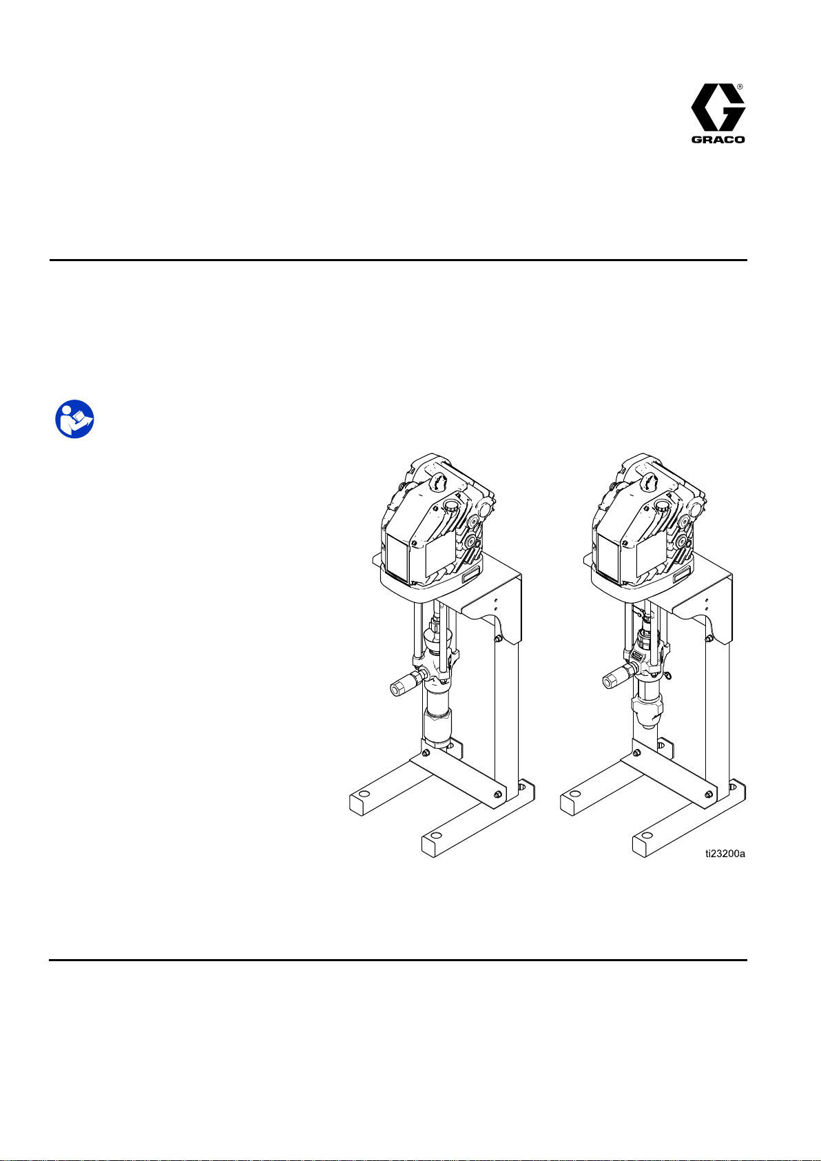
Instructions-Parts
E
Flo®
E E
- --Flo® Flo®
DC
DC DC
2
Ball
2 2
- --Ball Ball
Piston
Piston Piston
Pumps
Pumps Pumps
333389F
EN
Electric
Electric Electric
For
For For
See Technical Specictations for
Maximum Working Pressure.
See page 3 for model part numbers and
approvals information.
drive
piston
drive drive
professional
professional professional
piston piston
Important
Important Important
ReadallwarningsandinstructionsinthismanualandintheE-Flo
DCMotorandE-FloDCThreePhasemanualsbeforeusingthe
equipment.Savetheseinstructions.
pumps
pumps pumps
use
only.
use use
only. only.
Safety
Safety Safety
for
for for
Instructions
Instructions Instructions
low
to
low low
medium
to to
medium medium
volume
volume volume
paint
circulation
paint paint
circulation circulation
applications.
applications. applications.
PROVENQUALITY.LEADINGTECHNOLOGY.
Page 2

Contents
Contents Contents
Models...............................................................3
RelatedManuals................................................4
Warnings...........................................................5
Installation..........................................................8
Location......................................................8
MountthePump..........................................8
PowerRequirements....................................8
ConnecttheSupplyWiring...........................11
Grounding...................................................12
FluidLineAccessories.................................13
ChecktheOilLevelBeforeUsingthe
Equipment......................................13
FlushBeforeUsingtheEquipment................13
ControlModuleAccessory............................13
Operation...........................................................14
Startup........................................................14
Shutdown....................................................14
PressureReliefProcedure............................14
Maintenance......................................................15
PreventiveMaintenanceSchedule................15
ChangetheOil.............................................15
ChecktheOilLevel......................................15
WetCups....................................................15
Flushing......................................................15
Troubleshooting..................................................16
Repair................................................................17
Dura-FloLowers..........................................17
XtremeLowers............................................19
Parts..................................................................21
XtremePumpAssembly...............................21
Dura-FloPumpAssembly.............................23
PumpMatrix................................................25
Dimensions........................................................29
MountingHolePatterns.......................................30
StandMount................................................30
WallMount..................................................31
PerformanceCharts............................................32
TechnicalSpecications......................................35
CaliforniaProposition65.....................................35
2
333389F
Page 3
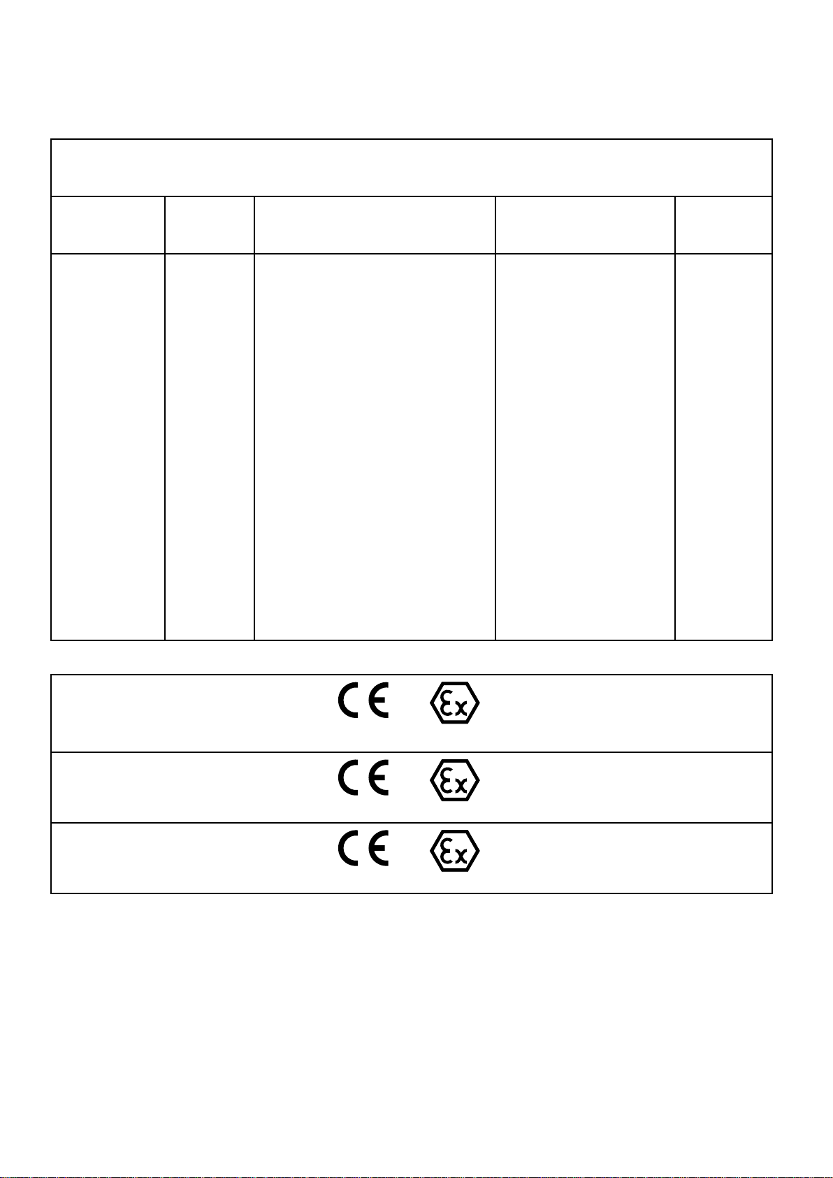
Models
Models Models
Thepartnumberforyourequipmentisprintedontheequipmentidenticationlabel.Thepartnumber
includesdigitsfromeachofthefollowingcategories,dependingonthecongurationofyourequipment.See
PumpMatrix,page25foracompletelistofpumppartnumbers.
Models
Pump
Type
and
Flo
DC
E EE- --Flo Flo
(ES)
(ES) (ES)
ES
Pump
DC DC
Pump Pump
Lower
Lower Lower
Size
Size Size
(7,
(7, (7,
7:145cc
8:180cc
9:220cc
0:290cc
8, 8,8,9, 9,9,or or
Pump
Pump Pump
Motor,
Motor, Motor,
(3–8
(3–8 (3–8
or ororC, C,
or
0)
0) 0)
3:2hp,Basic,SinglePhase
ATEX•FM•IECEx
4:2hp,Advanced,SinglePhase
ATEX•FM•IECEx
7:2hp,Basic,SinglePhase
ATEX•IECEx•TIIS•KCS
8:2hp,Advanced,SinglePhase
ATEX•IECEx•TIIS•KCS
C:2hp,Basic,ThreePhase
ATEX•FM•IECEx
D:2hp,Advanced,ThreePhase
ATEX•FM•IECEx
G:2hp,Basic,ThreePhase
ATEX•IECEx•TIIS•KCS
H:2hp,Advanced,ThreePhase
ATEX•IECEx•TIIS•KCS
Controls,
Controls, Controls,
C,
Approvals
Approvals Approvals
D,
G,
H)
D, D,
G, G,
H) H)
Pump Pump
Type Type
(4,
or
(4, (4,
4:CarbonSteelwiththree
Xtremepackingsandtwo
leatherpackings
5:StainlessSteelwithfour
leatherpackingsandone
PTFEpacking
6:StainlessSteelwith
leatherpackingsandPTFE
packings
6)
5, 5,5,or or
6) 6)
Fittings
and and
Fittings Fittings
Mounting
Mounting Mounting
(0,
(0, (0,
0:None
1:Stand
2:Wall
Bracket
Type
Type Type
or
2)
1, 1,1,or or
2) 2)
Approvals
Approvals Approvals
Singlephaseandthreephasepumpswith
basicmotors:
ESx3xxmodels
ESx7xxmodels
Singlephasepumpswithadvancedmotors:
ESx4xxmodels
ESx8xxmodels
Threephasepumpswithadvancedmotors:
ESxDxxmodels
ESxHxxmodels
NOTE:
NOTE: NOTE:
SeetheE-FloDCMotormanualsformotorapprovalsinformation.
ESxCxxmodels
ESxGxxmodels
G
II IIII2 22G G
Ex
db
IIA
T3
Gb
Ex Ex
db db
h hhIIA IIA
T3 T3
(1)
II IIII2 22(1) (1)
Ex
db
[ia
Ex Ex
db db
Ex
db
Ex Ex
db db
Ga]
h hh[ia [ia
Ga] Ga]
(1)
II IIII2 22(1) (1)
[ia
op
h hh[ia [ia
op op
X
Gb Gb
X X
G
G G
IIA
T3
Gb
IIA IIA
T3 T3
G
G G
Ga]
is isisGa] Ga]
X
Gb Gb
X X
IIA
T3
Gb
IIA IIA
T3 T3
X
Gb Gb
X X
333389F 3
Page 4

RelatedManuals
Related
Related Related
Manual
Manual Manual
3A2526
3A2527
3A4409
311762
311827
332103
No.
No. No.
Manuals
Manuals Manuals
Description
Description Description
E-FloDCMotor,Instructions-Parts
E-FloDCControlModuleKit,Instructions-Parts
E-FloDCMotor,ThreePhaseInstructions-Parts
Xtreme®Lowers,Instructions-Parts
Dura-Flo®Lowers,Instructions-Parts
DisplayControlModule(DCM)andAdvancedDisplayControlModule(ADCM)
4
333389F
Page 5
Warnings
Warnings Warnings
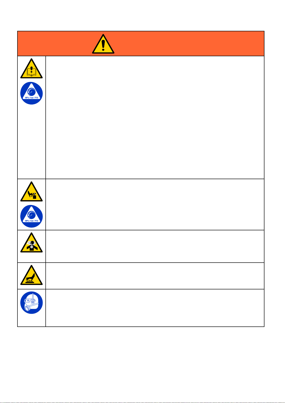
Thefollowingwarningsareforthesetup,use,grounding,maintenance,andrepairofthisequipment.Theexclamation
pointsymbolalertsyoutoageneralwarningandthehazardsymbolsrefertoprocedure-specicrisks.Whenthese
symbolsappearinthebodyofthismanual,referbacktotheseWarnings.Product-specichazardsymbolsand
warningsnotcoveredinthissectionmayappearthroughoutthebodyofthismanualwhereapplicable.
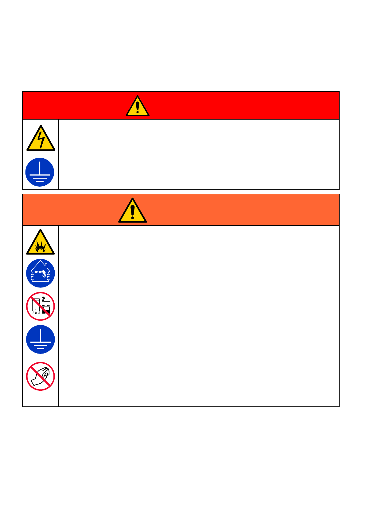
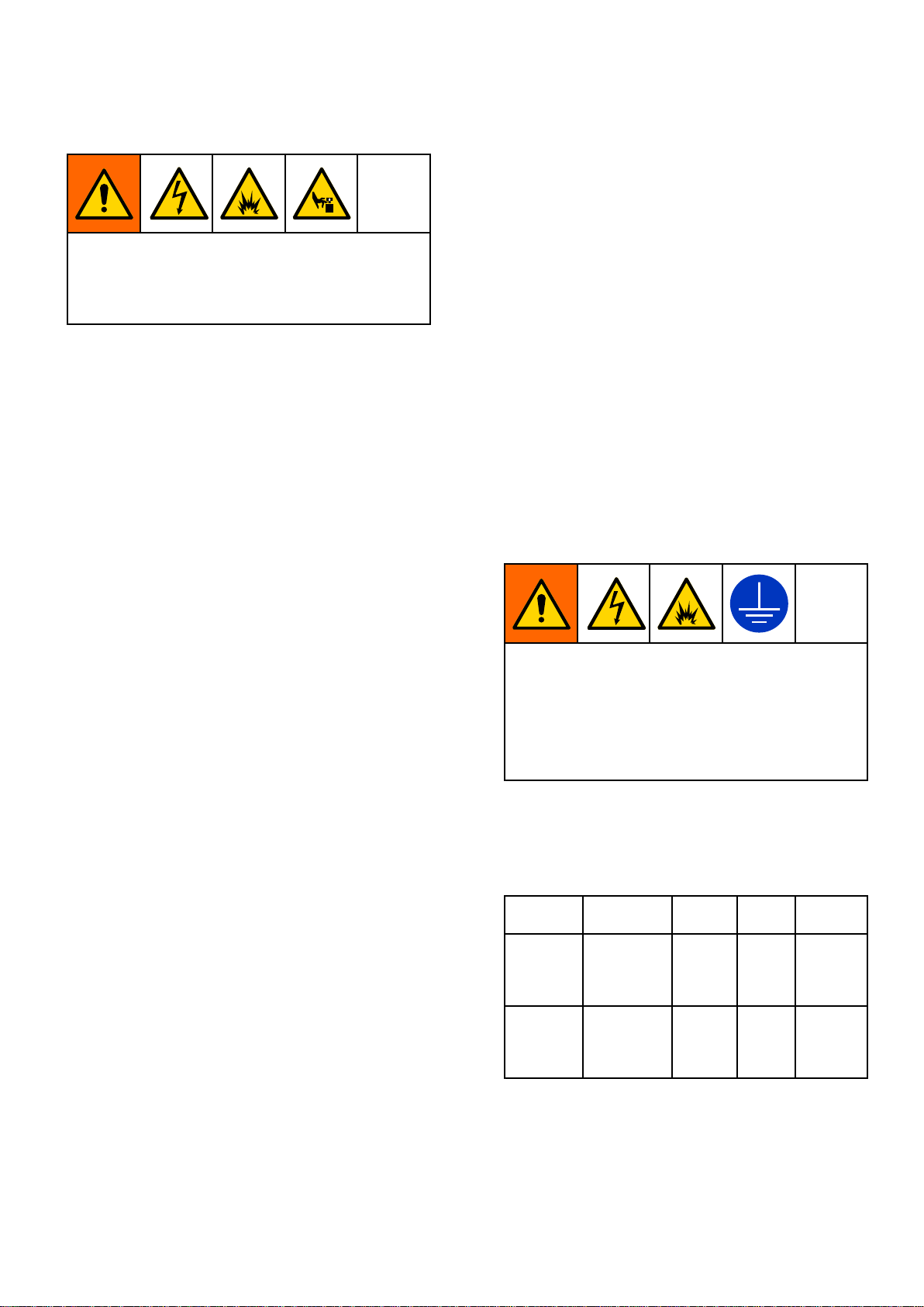
DANGER
DANGER DANGER
SEVERE
SEVERE SEVERE
Thisequipmentcanbepoweredbymorethan240V.Contactwiththisvoltagewillcausedeath
orseriousinjury.
•Turnoffanddisconnectthepoweratthemainswitchbeforedisconnectinganycablesandbefore
servicingequipment.
•Thisequipmentmustbegrounded.Connectonlytoagroundedpowersource.
•Allelectricalwiringmustbedonebyaqualiedelectricianandcomplywithalllocalcodesand
regulations.
ELECTRIC
ELECTRIC ELECTRIC
SHOCK
SHOCK SHOCK
HAZARD
HAZARD HAZARD
Warnings
WARNING
WARNING WARNING
FIRE
AND
FIRE FIRE
Flammablefumes,suchassolventandpaintfumes,intheworkareacanigniteorexplode.Paintor
solventowingthroughtheequipmentcancausestaticsparking.Tohelppreventreandexplosion:
•Useequipmentonlyinawell-ventilatedarea.
•Eliminateallignitionsourcessuchaspilotlights,cigarettes,portableelectriclamps,andplastic
dropcloths(potentialstaticsparking).
•Groundallequipmentintheworkarea.SeeGrounding Grounding
•Neversprayorushsolventathighpressure.
•Keeptheworkareafreeofdebris,includingsolvent,rags,andgasoline.
•Donotplugorunplugpowercords,orturnpowerorlightswitchesonoroffwhenammable
fumesarepresent.
•Useonlygroundedhoses.
•Holdthegunrmlytothesideofagroundedpailwhentriggeringintoapail.Donotusepail
linersunlesstheyareantistaticorconductive.
Stop
•Stop Stop
youidentifyandcorrecttheproblem.
•Keepaworkingreextinguisherintheworkarea.
Staticchargemaybuilduponplasticpartsduringcleaningandcoulddischargeandigniteammable
vapors.Tohelppreventreandexplosion:
•Cleanplasticpartsonlyinwellventilatedarea.
•Donotcleanwithadrycloth.
•Donotoperateelectrostaticgunsinequipmentworkarea.
EXPLOSION
AND AND
EXPLOSION EXPLOSION
operation
operation operation
immediately
immediately immediately
HAZARD
HAZARD HAZARD
Grounding
ifstaticsparkingoccursoryoufeelashock.Donotuseequipmentuntil
instructions.
333389F 5
Page 6
Warnings
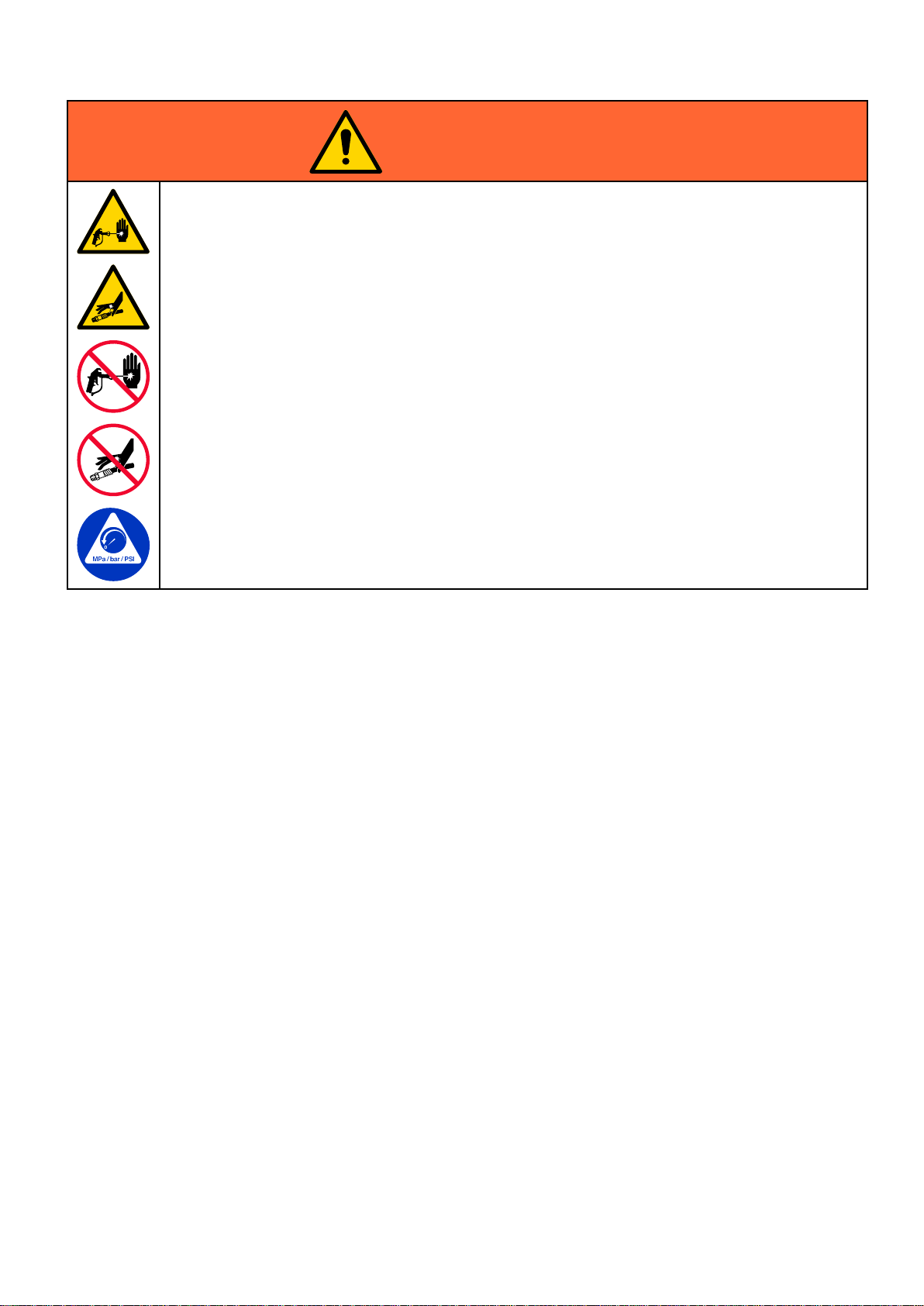
WARNING
WARNING WARNING
SKIN
INJECTION
SKIN SKIN
INJECTION INJECTION
High-pressureuidfromdispensingdevice,hoseleaks,orrupturedcomponentswillpierceskin.
Thismaylooklikejustacut,butitisaseriousinjurythatcanresultinamputation.Get Get
surgical
surgical surgical
•Engagethetriggerlockwhennotdispensing.
•Donotpointthedispensingdeviceatanyoneoratanypartofthebody.
•Donotputyourhandovertheuidoutlet.
•Donotstopordeectleakswithyourhand,body,glove,orrag.
•FollowthePressure Pressure
•Tightenalluidconnectionsbeforeoperatingtheequipment.
•Checkhosesandcouplingsdaily.Replacewornordamagedpartsimmediately.
treatment.
treatment. treatment.
servicingequipment.
HAZARD
HAZARD HAZARD
Get
immediate
immediate immediate
Pressure
Relief
Procedure
Relief Relief
Procedure Procedure
whenyoustopdispensingandbeforecleaning,checking,or
6 333389F
Page 7
WARNING
WARNING WARNING
EQUIPMENT
EQUIPMENT EQUIPMENT
Misusecancausedeathorseriousinjury.
•Donotoperatetheunitwhenfatiguedorundertheinuenceofdrugsoralcohol.
•Donotexceedthemaximumworkingpressureortemperatureratingofthelowestratedsystem
component.SeeTechnical Technical
•Useuidsandsolventsthatarecompatiblewithequipmentwettedparts.SeeTechnical Technical
Specications
Specications Specications
completeinformationaboutyourmaterial,requestSafetyDataSheets(SDSs)fromyourdistributor
orretailer.
•Donotleavetheworkareawhileequipmentisenergizedorunderpressure.
•TurnoffallequipmentandfollowthePressure Pressure
•Checkequipmentdaily.Repairorreplacewornordamagedpartsimmediatelywithgenuine
manufacturer’sreplacementpartsonly.
•Donotalterormodifyequipment.Alterationsormodicationsmayvoidagencyapprovalsand
createsafetyhazards.
•Makesureallequipmentisratedandapprovedfortheenvironmentinwhichyouareusingit.
•Useequipmentonlyforitsintendedpurpose.Callyourdistributorforinformation.
•Routehosesandcablesawayfromtrafcareas,sharpedges,movingparts,andhotsurfaces.
•Donotkinkoroverbendhosesorusehosestopullequipment.
•Keepchildrenandanimalsawayfromworkarea.
•Complywithallapplicablesafetyregulations.
MOVING
MOVING MOVING
Movingpartscanpinch,cut,oramputatengersandotherbodyparts.
MISUSE
MISUSE MISUSE
PARTS
PARTS PARTS
HAZARD
HAZARD HAZARD
Technical
inallequipmentmanuals.Readuidandsolventmanufacturer’swarnings.For
HAZARD
HAZARD HAZARD
Specications
Specications Specications
Pressure
inallequipmentmanuals.
Relief
Relief Relief
Technical
Procedure
Procedure Procedure
whenequipmentisnotinuse.
Warnings
•Keepclearofmovingparts.
•Donotoperateequipmentwithprotectiveguardsorcoversremoved.
•Pressurizedequipmentcanstartwithoutwarning.Beforechecking,moving,orservicingequipment,
followthePressure Pressure
TOXIC
TOXIC TOXIC
Toxicuidsorfumescancauseseriousinjuryordeathifsplashedintheeyesoronskin,inhaled,or
swallowed.
•ReadSafetyDataSheets(SDSs)toknowthespecichazardsoftheuidsyouareusing.
•Storehazardousuidinapprovedcontainers,anddisposeofitaccordingtoapplicableguidelines.
BURN
BURN BURN
Equipmentsurfacesanduidthat’sheatedcanbecomeveryhotduringoperation.Toavoidsevere
burns:
•Donottouchhotuidorequipment.
PERSONAL
PERSONAL PERSONAL
Wearappropriateprotectiveequipmentwhenintheworkareatohelppreventseriousinjury,including
eyeinjury,hearingloss,inhalationoftoxicfumes,andburns.Protectiveequipmentincludesbut
isnotlimitedto:
•Protectiveeyewearandhearingprotection.
•Respirators,protectiveclothing,andglovesasrecommendedbytheuidandsolventmanufacturer.
Pressure
FLUID
FLUID FLUID
HAZARD
HAZARD HAZARD
OR
OR OR
PROTECTIVE
PROTECTIVE PROTECTIVE
Relief
Procedure
Relief Relief
Procedure Procedure
FUMES
FUMES FUMES
EQUIPMENT
EQUIPMENT EQUIPMENT
anddisconnectallpowersources.
333389F
7
Page 8
Installation
Installation
Installation Installation
Installationofthisequipmentinvolvespotentially
hazardousprocedures.Onlytrainedandqualied
personnelwhohavereadandwhounderstand
theinformationinthismanualshouldinstallthis
equipment.
Location
Location Location
Whenselectingthelocationfortheequipment,keep
thefollowinginmind:
•Theremustbesufcientspaceonallsidesof
theequipmentforinstallation,operatoraccess,
maintenance,andaircirculation.
•Ensurethatthemountingsurfaceandmounting
hardwarearestrongenoughtosupporttheweight
oftheequipment,uid,hoses,andstresscaused
duringoperation.
•Theremustbeastart/stopcontrol(C)
withineasyreachoftheequipment.See
TypicalInstallation,page10.
Wall
Mount
Wall Wall
Mount Mount
SeeWallMountingHolePattern,page31.
1.Selectasolidpositiononawallforthemounting
bracket.Thewallshouldbecapableofsupporting
thepumpandaccessoriesthatwillbeattached
tothebracket,anyadditionalweightoftheuid
usedinthepump,andanystressorstrainthat
maybeappliedduringpumpoperation.
2.Drillfour7/16in.(11mm)diameterholesforthe
mountingbolts,approximately5ft(1.5m)above
theoor,usingthewallbracketasatemplate.
Useanyofthethreemountingholegroupings
3.Boltthebracketsecurelytothewall.Usebolts
designedtoholdinthewall’sconstruction.
4.Placethepumpandaccessoriesoverthe
bracket’smountingholesandsecurewithscrews
(5)andwashers(4)supplied.
Power
Power Power
Requirements
Requirements Requirements
Mount
Mount Mount
Stand
Stand Stand
SeeStandMountingHolePattern,page30
1.Selectalevelsurfaceforthestandtobemounted
2.SecurethestandtotheoorwithM19(5/8in.)
3.Placethepumpandaccessoriesoverthe
4.Useshimstolevelthepumpasrequired.
the
Pump
the the
Pump Pump
Mount
Mount Mount
to.
bolts.Useboltsthatengageatleast152mm
(6in.)intotheoortopreventthepumpfrom
tipping.
bracket’smountingholesandsecurewithbolts
(5)andwashers(4)supplied.
Improperwiringmaycauseelectricshockorother
seriousinjuryifworkisnotperformedproperly.
•Thisequipmentmustbegrounded.Connect
onlytoagroundedpowersource.
•Allelectricalwiringmustbedonebyaqualied
electricianandcomplywithalllocalcodesand
regulations.
Thesystemrequiresadedicatedcircuitprotected
withacircuitbreaker.Seethefollowingtablefor
powerrequirements.
Table
Table Table
Model
Model Model
ESx3xx
ESx4xx
ESx7xx
ESx8xx
ESxCxx
ESxDxx
ESxGxx
ESxHxx
Power
1 11. ..Power Power
Specications
Specications Specications
Voltage
Voltage Voltage
200–250
Vac
380–480
Vac
Phase
Phase Phase
150/602.9kVA
350/603.0kVA
Hz
Hz Hz
Power
Power Power
8 333389F
Page 9

Installation
Hazardous
Hazardous Hazardous
Requirements
Requirements Requirements
Explosion
Explosion Explosion
Allelectricalwiringinthehazardousareamustbe
encasedinClassI,DivisionI,GroupDapproved
explosion-proofconduit.Followallnational,state,
andlocalelectriccodes.
Aconduitseal(D)isrequiredwithin18in.(457mm)
ofthemotorfortheUSandCanada.SeeFigs.3
and4.
Allcablesmustberatedat70°C(158°F).
Area
Cabling
Area Area
Cabling Cabling
Proof
Proof Proof
and
Conduit
and and
Conduit Conduit
Flame
Flame Flame
Useappropriateconduit,connectors,andcable
glandsratedforATEXII2G.FollowallNational,
State,andLocalelectriccodes.
Allcableglandsandcablesmustberatedat70°C
(158°F).
Proof
Proof Proof
(ATEX)
(ATEX) (ATEX)
333389F 9
Page 10
Installation
Typical
Typical Typical
Installation
Installation Installation
NON
HAZARDOUS
NON NON
- --HAZARDOUS HAZARDOUS
LOCATION
LOCATION LOCATION
HAZARDOUS
HAZARDOUS HAZARDOUS
LOCATION
LOCATION LOCATION
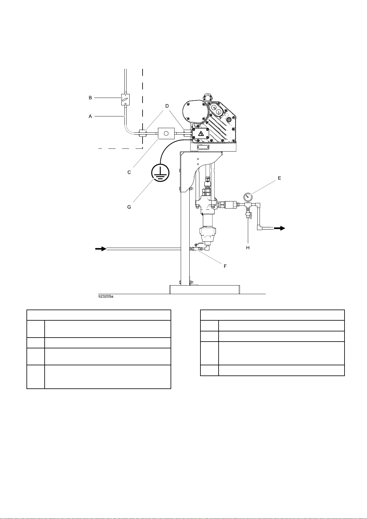
Figure1TypicalInstallation
Key
for
Fig.
Key Key
for for
A
BDisconnect,withlock
CStart/StopControl(mustbeapprovedfor
D
1
Fig. Fig.
1 1
ElectricalSupply(mustbesealedconduit
approvedforuseinhazardouslocations)
useinhazardouslocations)
ExplosionProofConduitSeal.Required
within18in.(457mm)ofthemotorforthe
USandCanada.
Key
for
Fig.
Key Key
for for
E
F
GPumpGroundWire.Twogroundterminals
HFluidDrainValve
1
Fig. Fig.
1 1
FluidPressureGauge
FluidShutoffValve
areprovidediflocalcoderequiresredundant
groundingconnections.
10 333389F
Page 11
Installation
Connect
Connect Connect
Improperwiringmaycauseelectricshockorother
seriousinjuryifworkisnotperformedproperly.
•Thisequipmentmustbegrounded.Connect
onlytoagroundedpowersource.
•Allelectricalwiringmustbedonebyaqualied
electricianandcomplywithalllocalcodesand
regulations.
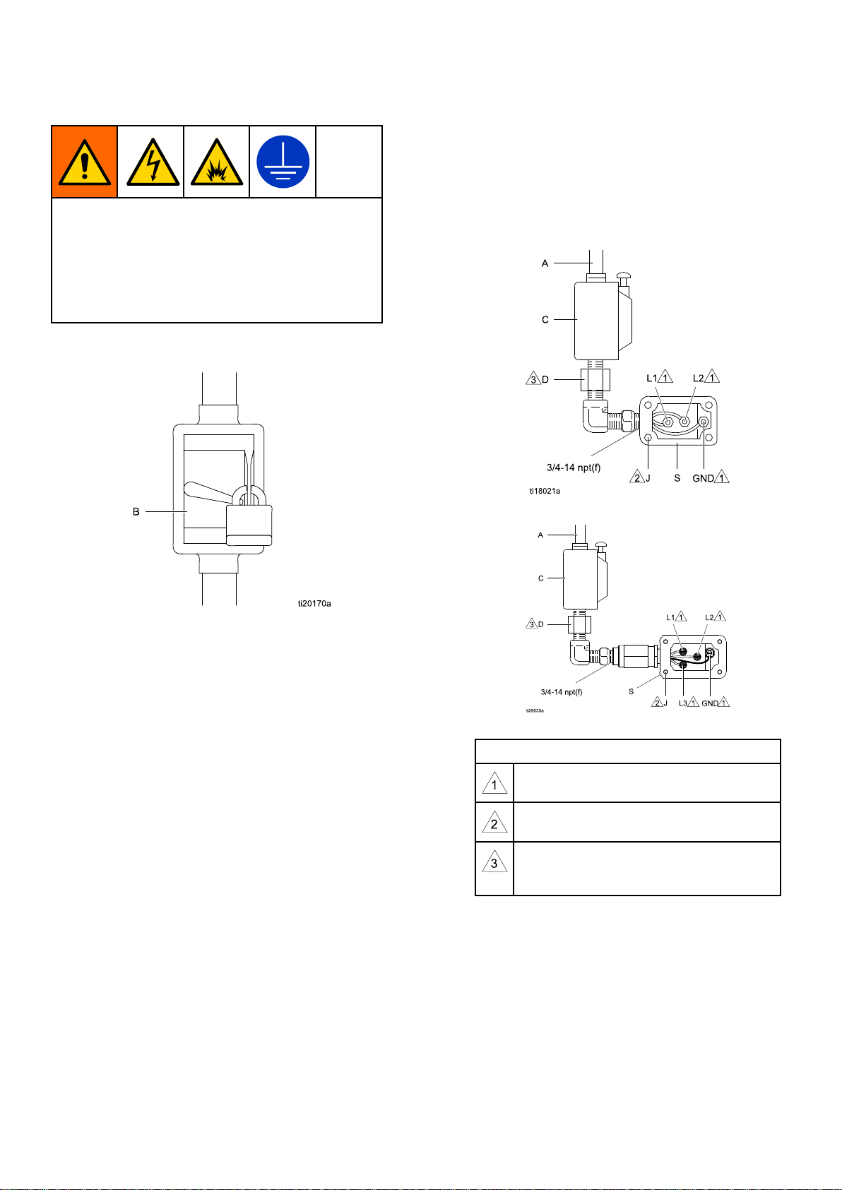
1.Ensurethatthedisconnect(B,Fig2)isshutoff
andlockedout.
the
Supply
the the
Supply Supply
Wiring
Wiring Wiring
3.Opentheelectricalcompartment(S)onthe
motor.
4.Bringthesupplywiresintotheelectrical
compartmentthroughthe3/4–14npt(f)inletport.
Connectthewirestotheterminals,asshownin
Figs.3and4.Torquetheterminalnutsto15
Do
not
in-lb(1.7N•m)maximum.Do Do
Figure3ConnectthePowerWires,SinglePhase
over-torque.
not not
over-torque. over-torque.
Figure2LockedOutDisconnect
2.SeeFigs.3and4.Installastart/stopcontrol(C)
intheelectricalsupplyline(A),withineasyreach
oftheequipment.Thestart/stopcontrolmustbe
approvedforuseinhazardouslocations.
Figure4ConnectthePowerWires,ThreePhase
Notes
for
Notes Notes
5.Closetheelectricalcompartment.Torquethe
coverscrewsto15ft-lb(20.3N•m).
Figs.
for for
Figs. Figs.
Tightenallterminalnutsto15in-lb(1.7
N•m)maximum.Do Do
Tightencoverscrewsto15ft-lb(20.3
N•m).
Aconduitseal(D)isrequiredwithin18
in.(457mm)ofthemotorfortheUSand
Canada.
and
4
3 33and and
4 4
Do
not
over
not not
torque.
over over
- --torque. torque.
333389F
11
Page 12

Installation
Grounding
Grounding Grounding
Thisequipmentmustbegroundedtoreducethe
riskofstaticsparkingandelectricshock.Electric
orstaticsparkingcancausefumestoigniteor
explode.Impropergroundingcancauseelectric
shock.Groundingprovidesanescapewireforthe
electriccurrent.
1.Connectthesupplygroundwireinthe
electricalcompartmentasshownin
ConnecttheSupplyWiring,page11.
2.ConnectagroundwireasshowninFig.5.
Loosenthegroundscrewandattachaground
wire(Y,Gracopart222011,notsupplied).
Tightenthegroundscrewsecurely.Connect
theotherendofthegroundwiretoatrueearth
ground.
To
6.To To
maintain
maintain maintain
or
relieving
or or
relieving relieving
gunorvalvermlytothesideofagrounded
metalpail,thentriggerthegunoropenthevalve.
grounding
grounding grounding
pressure:
pressure: pressure:
continuity
continuity continuity
Holdmetalpartofthespray
when
ushing
when when
ushing ushing
Figure5GroundWire
NOTE:
NOTE: NOTE:
ofacontrolmodule.Allpumpsconnectedtoa
commoncontrolmodulemustbegroundedto
thesamegroundpoint.Differentgroundpoints
(unequalpotential)maycausecurrenttoow
throughcomponentcables,causingincorrect
signals.
Fluid
3.Fluid Fluid
hoseswithamaximumof500ft.(150m)
combinedhoselengthtoensuregrounding
continuity.Checktheelectricalresistanceof
hoses.Iftotalresistancetogroundexceeds25
megohms,replacehoseimmediately
Fluid
4.Fluid Fluid
Solvent
5.Solvent Solvent
localcode.Useonlyconductivemetalpails,
placedonagroundedsurface.Donotplace
thepailonanon-conductivesurface,suchas
paperorcardboard,whichinterruptsgrounding
continuity.
Advancedmodelsrequireinstallation
Pump
Pump Pump
ESx4xx
ESx8xx
ESxDxx
ESxHxx
hoses:
hoses: hoses:
supply
supply supply
pails
pails pails
Useonlyelectricallyconductive
container:
container: container:
used
when
used used
when when
Control
Control Control
24P822
24X599
17V232
17V233
Module Module
Followyourlocalcode.
ushing:
ushing: ushing:
Module
12
Followyour
333389F
Page 13

Installation
Fluid
Fluid Fluid
Installthefollowingaccessoriesasshownin
Fig.1,usingadaptersasnecessary.Alluid
linesandaccessoriesmustberatedtothe
maximumworkingpressureofthepump.See
TechnicalSpecications,page35.
•Fluid Fluid
•Fluid Fluid
•Fluid Fluid
Check
Check Check
Equipment
Equipment Equipment
Themotorispre-lledwithoil.Beforeusingthe
equipment,replacetheshippingplugwiththevented
llcap(P)thatisincludedwiththemotor.
Line
Line Line
Fluid
drain
drain drain
relieveuidpressureinthehoseandcirculation
system.
Fluid
pressure pressure
adjustmentoftheuidpressure.
Fluid
shutoff
shutoff shutoff
Accessories
Accessories Accessories
valve
(H):
valve valve
(H): (H):
requiredinyoursystem,to
pressure
the
the the
gauge
gauge gauge
valve
valve valve
Oil
Oil Oil
(F):
(F): (F):
Level
Level Level
(E):
(E): (E):
shutsoffuidow.
formoreprecise
Before
Before Before
Using
Using Using
Flush
Flush Flush
Thepumpuidsectionwastestedwithlightweight
oil,whichisleftintheuidpassagestoprotectparts.
Toavoidcontaminatingyouruidwithoil,ushthe
equipmentwithacompatiblesolventbeforeusing
theequipment.
Control
Control Control
TheControlModuleAccessoryisrequiredwith
AdvancedE-FloDCmotorstoprovidetheinterface
foruserstoenterselectionsandviewinformation
relatedtosetupandoperation.SeetheControl
ModuleAccessoryKitmanualforinstallationand
the
the the
operationinformation.
Before
Before Before
Module
Module Module
Using
Using Using
the
Equipment
the the
Equipment Equipment
Accessory
Accessory Accessory
Figure6SightglassandOilFillCap
333389F 13
Page 14

Operation
Operation
Operation Operation
Startup
Startup Startup
Tooperatethepump,followtheStartupinstructions
fortheBasicorAdvancedmotorintheMotormanual.
TheAdvancedE-FloDCmotorsrequireinstallation
ofaControlModuleAccessoryKit(seetable)to
providetheinterfaceforuserstoenterselectionsand
viewinformationrelatedtosetupandoperation.See
theControlModuleAccessoryKitmanual3A2527for
installationandoperationinformation.
Pump
Pump Pump
ESx4xx
ESx8xx
ESxDxx
ESxHxx
Runthepumpataslowspeeduntiltheuidlinesare
primedandallairisforcedoutofthesystem.
DonotuseXtremepumplowersforwaterborne
paints,becausethepumpsarecarbonsteeland
waterbornepaintswillcausethemtorust.
Shutdown
Shutdown Shutdown
Control
Control Control
24P822
24X599
17V232
17V233
NOTICE
NOTICE NOTICE
Module
Module Module
Pressure
Pressure Pressure
Thisequipmentstayspressurizeduntilpressure
ismanuallyrelieved.Tohelppreventserious
injuryfrompressurizeduid,suchasskininjection,
splashinguid,andmovingparts,followthe
PressureReliefProcedurewhenyoustopspraying
andbeforecleaning,checking,orservicingthe
equipment.
1.Disengagethestart/stopcontrol(C).SeeFig.1.
2.Shutoffandlockoutthedisconnect(B).
3.Opentheuiddrainvalve(H),havingawaste
containerreadytocatchdrainage.Leaveopen
untilyouarereadytopressurizesystemagain.
Relief
Relief Relief
FollowthePressureReliefProcedure
wheneveryouseethissymbol.
Procedure
Procedure Procedure
FollowthePressureReliefProcedure,page14.Stop
thepumpatthebottomofitsstroketopreventuid
fromdryingontheexposeddisplacementrodand
damagingthethroatpackings.
14
333389F
Page 15

Maintenance
Maintenance
Maintenance Maintenance
Seethemotormanualforrequiredmotor
maintenanceprocedures.
Preventive
Preventive Preventive
Theoperatingconditionsofyourparticularsystem
determinehowoftenmaintenanceisrequired.
Establishapreventivemaintenancescheduleby
recordingwhenandwhatkindofmaintenanceis
needed,andthendeterminearegularschedulefor
checkingyoursystem.
Change
Change Change
NOTE:
NOTE: NOTE:
200,000–300,000cycles.Afterthebreak-inperiod,
changetheoilonceayear.
1.SeeFig.7.Placeaminimum2quart(1.9liter)
2.Reinstalltheoildrainplug(25).Torqueto25–30
3.SeeFig.8.Openthellcap(P)andaddGraco
4.Reinstallthellcap.
Changetheoilafterabreak-inperiodof
containerundertheoildrainport.Removethe
oildrainplug(25).Allowalloiltodrainfromthe
motor.
ft-lb(34–40N•m).
PartNo.16W645ISO220silicone-freesynthetic
gearoil.Checktheoillevelinthesightglass(K).
Filluntiltheoillevelisnearthehalfwaypointof
thesightglass.Theoilcapacityisapproximately
1.5quarts(1.4liters).Do Do
Maintenance
Maintenance Maintenance
the
Oil
the the
Oil Oil
Do
Schedule
Schedule Schedule
not
overll.
not not
overll. overll.
Check
Check Check
SeeFig.8.Checktheoillevelinthesightglass(K).
Theoillevelshouldbenearthehalfwaypointofthe
sightglasswhentheunitisnotrunning.Iflow,open
thellcap(P)andaddGracoPartNo.16W645ISO
220silicone-freesyntheticgearoilasrequired.The
oilcapacityisapproximately1.5quarts(1.4liters).
Do
Do Do
Figure8SightglassandOilFillCap
Wet
Wet Wet
Checkthewetcupdaily.Keepthewetcup1/3lled
withGracoThroatSealLiquid(TSL™)orcompatible
solvent.
the
Oil
the the
not
overll.
not not
overll. overll.
Cups
Cups Cups
Level
Oil Oil
Level Level
Flushing
Flushing Flushing
Toavoidreandexplosion,alwaysground
equipmentandwastecontainers.Toavoidstatic
sparkingandinjuryfromsplashing,alwaysushat
thelowestpossiblepressure.
•Flushbeforechanginguids,beforeuidcandry
intheequipment,attheendoftheday,before
storing,andbeforerepairingequipment.
•Flushatthelowestpressurepossible.Check
connectorsforleaksandtightenasnecessary.
•Flushwithauidthatiscompatiblewiththeuid
Figure7OilDrainPlug
333389F 15
beingdispensedandtheequipmentwettedparts.
Page 16
Troubleshooting
Troubleshooting
Troubleshooting Troubleshooting
•FollowthePressureReliefProcedure,page
14beforecheckingorservicingtheequipment.
•Checkallpossibleproblemsandcausesbefore
disassembly.
Problem
Problem Problem
Pumpoutputlowonbothstrokes.
Pumpoutputlowononlyonestroke.
Nooutput.Improperlyinstalledballcheck
Pumpoperateserratically.
Pumpwillnotoperate.
Cause
Cause Cause
Inadequatepower.
Exhausteduidsupply.Rellandreprimepump.
Cloggeduidoutletline,valves,etc.Clear.
Wornpistonpacking.
Heldopenorwornballcheckvalves.
Wornpistonpacking.
valves.
Exhausteduidsupply.Rellandreprimepump.
Heldopenorwornballcheckvalves.
Wornpistonpacking.
Inadequatepower.
Exhausteduidsupply.Rellandreprimepump.
•TheLEDonthemotorblinksifanerrorisdetected.
Error
Code
SeeError Error
manualformoreinformation.
Troubleshooting
Code Code
Troubleshooting Troubleshooting
Solution
Solution Solution
SeePowerRequirements,page8.
Replace.Seelowermanual.
Checkandrepair.Seelowermanual.
Replace.Seelowermanual.
Checkandrepair.Seelowermanual.
Checkandrepair.Seelowermanual.
Replace.Seelowermanual.
SeePowerRequirements,page8.
inthemotor
Cloggeduidoutletline,valves,etc.Clear.
Fluiddriedonpistonrod.
Disassembleandcleanpump.See
lowermanual.Infuture,stoppump
atbottomofstroke.
16 333389F
Page 17

Repair
Repair
Repair Repair
Dura
Dura Dura
Disassembly
Disassembly Disassembly
Toavoidcrushinginjuriesormusclestrains,use
cautionwhendisconnectingthelower.Itcanweigh
upto25kg(55lbs).
1.Stopthepumpatthebottomofitsstroke.
2.Relievethepressure.Follow
3.Disconnectthehosesfromthelowerandplug
Flo
Lowers
- --Flo Flo
Lowers Lowers
thePressureReliefProcedure,page14.
theendstopreventuidcontamination.
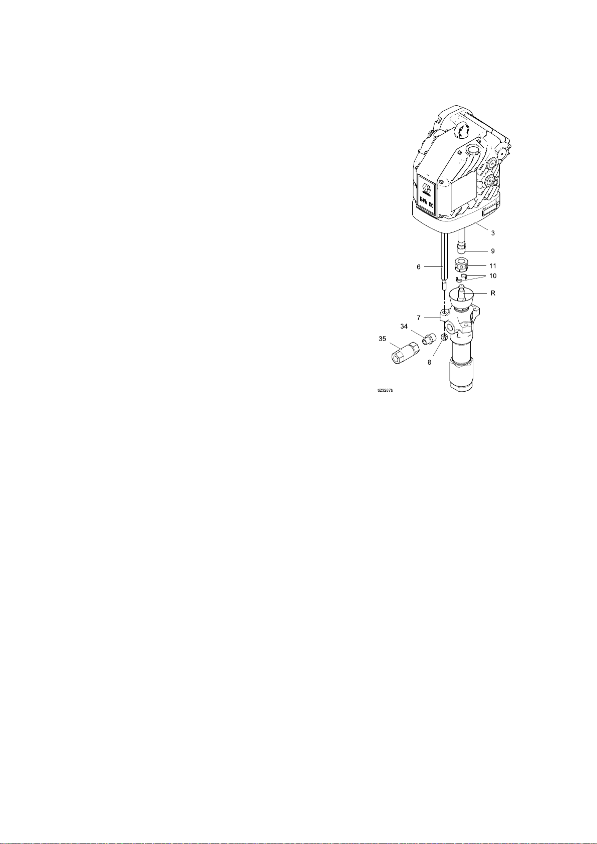
4.Loosenthecouplingnut(11)andremovethe
collars(10).SeeFig.9.
5.Removethecouplingnutfromthepistonrod(R).
6.Unscrewthelocknuts(8)fromthetierods(6).
7.Separatethemotor(3)andlower(7).
Torepairthelower,seetheDura-FloLower
instructionmanual311827.Thereareno
user-serviceablepartsinthemotor.Contactyour
Gracorepresentativeforassistance.
333389F
17
Page 18
Repair
Reassembly
Reassembly Reassembly
1.Ifthecouplingadapter(9)andtierods(6)have
notbeendisassembledfromthemotor(3),skip
tostep2.
Ifthecouplingadapter(9)andtierods(6)have
beendisassembledfromthemotor(3),follow
thesesteps:
a.Screwthetierods(6)intothemotor(3)and
torqueto50-60ft-lb(68-81N•m).
b.Screwthecouplingadapter(9)intothemotor
shaftandtorqueto90–100ft-lb(122–135
N•m).
c.Reassemblethepumptothemotor.Use
theapplicableinstructionsforyourpump
(Dura-Flo,page18orXtreme,page20).
d.Continuetostep2.
2.Assemblethecouplingnut(11)tothepistonrod
(R).
3.Orientthelower(7)tothemotor(3).Position
thelower(7)onthetierods(6).Lubricatethe
threadsofthetierods(6).
4.Screwthetierodlocknuts(8)ontothetierods
(6).Tightenthelocknuts(8)andtorqueto50-60
ft-lb(68-81N•m).
5.Insertthecollars(10)intothecouplingnut(11).
Tightenthecouplingnut(11)ontothecoupling
adapter(9)andtorqueto90–100ft-lb(122–135
N•m).
6.Flushandtestthepumpbeforereinstalling
itinthesystem.Connecthosesandush
thepump.Whileitispressurized,checkfor
smoothoperationandleaks.Adjustorrepair
asnecessarybeforereinstallinginthesystem.
Reconnectthepumpgroundwirebefore
operating.
NOTE:
NOTE: NOTE:
lowersrequireacheckvalve(35)tobeinstalled.
Figure9Dura-FloPumpAssembly
WhenusedwithE-FloDCmotors,Dura-Flo
18 333389F
Page 19

Repair
Xtreme
Xtreme Xtreme
Disassembly
Disassembly Disassembly
Toavoidcrushinginjuriesormusclestrains,use
cautionwhendisconnectingthelower.Itcanweigh
upto25kg(55lbs).
1.Stopthepumpatthebottomofitsstroke.
2.Relievethepressure.Follow
thePressureReliefProcedure,page14.
3.Disconnectthehosesfromthelowerandplug
theendstopreventuidcontamination.
4.Removeclip(2)andslidecouplingcover(10)up
toremovethecoupling(11).
Lowers
Lowers Lowers
5.Unscrewthenuts(8)andremovethelower(7).
Useawrenchtoholdthetierodatstokeepthe
rodsfromturning.
Torepairthelower,seetheXtremeLowerinstruction
manual311762.Therearenouser-serviceableparts
inthemotor.ContactyourGracorepresentativefor
assistance.
333389F 19
Page 20

Repair
Reassembly
Reassembly Reassembly
1.Ifthecouplingadapter(9)andtierods(6)have
notbeendisassembledfromthemotor(3),skip
tostep2.
Ifthecouplingadapter(9)andtierods(6)have
beendisassembledfromthemotor(3),follow
thesesteps:
a.Screwthetierods(6)intothemotor(3)and
torqueto50-60ft-lb(68-81N•m).
b.Screwthecouplingadapter(9)intothemotor
shaftandtorqueto90–100ft-lb(122–135
N•m).
c.Reassemblethepumptothemotor.Use
theapplicableinstructionsforyourpump
(Dura-Flo,page18orXtreme,page20).
d.Continuetostep2.
2.Orientthelower(7)tothemotor(3).Position
thelower(7)onthetierods(6).Lubricatethe
threadsofthetierods(6).
3.Screwthetierodlocknuts(8)ontothetierods
(6).Tightenthelocknuts(8)andtorqueto50-60
ft-lb(68-81N•m).
4.Raisethemotorshaft.Placethecouplingcover
(10)ontothecouplingadapter(9)andlowerthe
motorshaft.Placethecoupling(11)ontothe
lower(7)andslidethecouplingcover(10)over
thecoupling(11).Insertclip(2).
5.Flushandtestthepumpbeforereinstalling
itinthesystem.Connecthosesandush
thepump.Whileitispressurized,checkfor
smoothoperationandleaks.Adjustorrepair
asnecessarybeforereinstallinginthesystem.
Reconnectthepumpgroundwirebefore
operating.
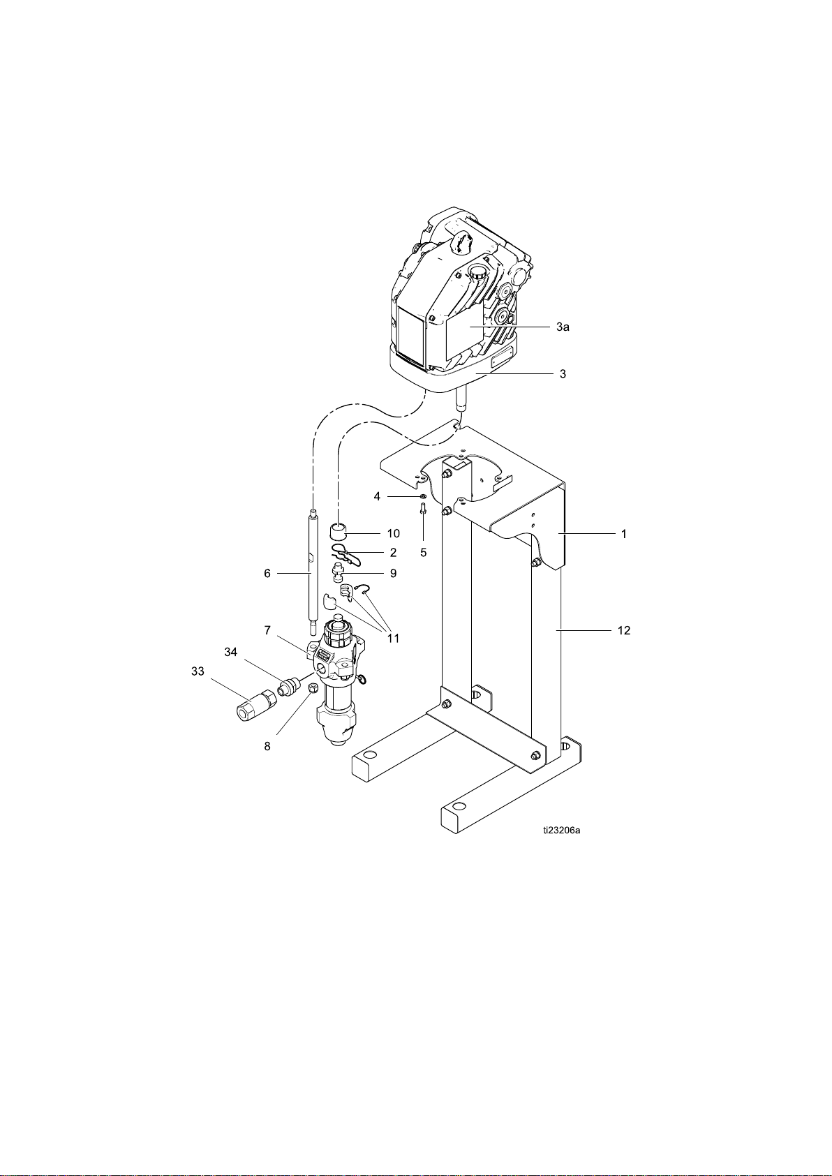
NOTE:
NOTE: NOTE:
lowersrequireacheckvalve(33)tobeinstalled.
Figure10XtremePumpAssembly
WhenusedwithE-FloDCmotors,Xtreme
20 333389F
Page 21
Parts
Parts
Parts Parts
Xtreme
Xtreme Xtreme
SeeModels,page3foranexplanationofthepumppartnumber.
Pump
Pump Pump
Assembly
Assembly Assembly
333389F
21
Page 22

Parts
Ref
Ref Ref
1
2244820
3
3a▲17J476LABEL,warning1
3b16W645
4
5
615F837
7
8107112NUT,lock,hex3
915H392ADAPTER1
10197340
11244819NUT,coupling1
12
3316T480VALVE,check1
Part
Part Part
SeePumpMatrix,page25
SeePumpMatrix,page25MOTOR,Basic;seemotormanual;includesitems
SeePumpMatrix,page25WASHER
SeePumpMatrix,page25BOLT
SeePumpMatrix,page25
SeePumpMatrix,page25STAND,oor
Description
Description Description
KIT,mountingbracket,pump;includesitems4
and5;seemanual311619
CLIP,hairpin
3aand3b
OIL,gear,synthetic;ISO220silicone-free;
1quart(0.95liter);notshown
ROD,tie
PUMP,displacement;seelowermanual1
COLLAR,coupling
Qty
Qty Qty
1
1
1
2
4
4
3
2
1
34
▲ReplacementDangerandWarninglabels,tags,
andcardsareavailableatnocost.
SeePumpMatrix,page25FITTING
1
22
333389F
Page 23

Parts
Dura
Dura Dura
SeeModels,page3foranexplanationofthepumppartnumber.
Flo
Pump
- --Flo Flo
Pump Pump
Assembly
Assembly Assembly
333389F 23
Page 24

Parts
Ref
Ref Ref
1
3
3a▲17J476LABEL,warning1
3b16W645
4
5
615H562
7
8101712NUT,lock3
915H370ADAPTER1
10184129
11186925NUT,coupling1
12
34
35
Part
Part Part
SeePumpMatrix,page25
SeePumpMatrix,page25MOTOR;BasicorAdvanced;seemotormanual;
SeePumpMatrix,page25WASHER
SeePumpMatrix,page25BOLT
SeePumpMatrix,page25
SeePumpMatrix,page25STAND,oor
SeePumpMatrix,page25FITTING
24S039
Description
Description Description
KIT,mountingbracket,pump;includesitems4
and5;seemanual311619
includesitems3aand3b
OIL,gear,synthetic;ISO220silicone-free;
1quart(0.95liter);notshown
ROD,tie
PUMP,displacement;seelowermanual1
COLLAR,coupling
VALVE,check1
Qty
Qty Qty
1
1
2
4
4
3
2
1
1
▲ReplacementDangerandWarninglabels,tags,
andcardsareavailableatnocost.
24
333389F
Page 25

Parts
Pump
Pump Pump
Pump
Pump Pump
Part
Part Part
ES0340
ES0341
ES0342
ES0350
ES0351
ES0352
ES7360
ES7361
ES7362
ES8340
ES8341
ES8342
ES8350
ES8351
ES8352
ES9340
ES9341
ES9342
ES9350
ES9351
ES9352
ES0440
ES0441
ES0442
ES0450
ES0451
ES0452
ES7440
ES7441
ES7442
ES7460
ES7461
ES7462
ES8440
ES8441
ES8442
ES8450
ES8451
ES8452
ES9440
ES9441
ES9442
ES9450
ES9451
ES9452
Matrix
Matrix Matrix
Pump
Pump Pump
No.
Series
No. No.
Series Series
Mounting
Mounting Mounting
(Ref
(Ref (Ref
A
A255143256193100133100101
A255143
————————————
A
A255143256193100133100101247192
A255143
————————————
A
A255143256193100133100101247168190724
A255143
————————————
A
A255143256193100133100101
A255143
————————————
A
A255143256193100133100101261657190724
A255143
————————————
A
A255143256193100133100101
A255143
————————————
A
A255143256193100133100101247190
A255143
————————————
A
A256143256193100133100101
A256143
————————————
A
A255143256193100133100101247192
A255143
————————————
A
A255143256193100133100101
A255143
————————————
A
A255143256193100133100101247168190724
A255143
————————————
A
A255143256193100133100101
A255143
————————————
A
A255143256193100133100101261657190724
A255143
————————————
A
A255143256193100133100101
A255143
————————————
A
A255143256193100133100101247190
A255143
Bracket
Bracket Bracket
1)
1) 1)
————————————
Floor
Floor Floor
(Ref
(Ref (Ref
———
———
———
———
———
———
———
———
———
———
———
———
———
———
———
Stand
Stand Stand
12)
12) 12)
Motor
Motor Motor
(Ref
(Ref (Ref
EM0021
EM0022
Washer
Washer Washer
3)
(Ref
3) 3)
4)
(Ref (Ref
4) 4)
100133100101
100133100101247192
100133100101247168190724
100133100101
100133100101261657190724
100133100101
100133100101247190
100133100101
100133100101247192
100133100101
100133100101247168190724
100133100101
100133100101261657190724
100133100101
100133100101247190
Bolt
Bolt Bolt
(Ref
5)
(Ref (Ref
5) 5)
Lower
Pump
Lower Lower
Pump Pump
(Ref
7)
(Ref (Ref
7) 7)
L29AC115C257
L29AC115C257
L29AC115C257
247192
247168190724
L18AC1
L18AC1
L18AC1
261657190724
L22AC115C257
L22AC115C257
L22AC115C257
247190
L29AC115C257
L29AC115C257
L29AC115C257
247192
L14AC1
L14AC1
L14AC1
247168190724
L18AC1
L18AC1
L18AC1
261657190724
L22AC115C257
L22AC115C257
L22AC115C257
247190
Fitting
Fitting Fitting
(Ref
34)
(Ref (Ref
34) 34)
16C946
16C946
16C946
175013
175013
175013
16C946
16C946
16C946
16C946
16C946
16C946
175013
175013
175013
175013
175013
175013
16C946
16C946
16C946
333389F 25
Page 26

Parts
Pump
Pump Pump
Part
Part Part
ES0740
ES0741
ES0742
ES0750
ES0751
ES0752
ES7760
ES7761
ES7762
ES8740
ES8741
ES8742
ES8750
ES8751
ES8752
ES9740
ES9741
ES9742
ES9750
ES9751
ES9752
ES0840
ES0841
ES0842
ES0850
ES0851
ES0852
ES7840
ES7841
ES7842
ES7860
ES7861
ES7862
ES8840
ES8841
ES8842
ES8850
ES8851
ES8852
ES9840
ES9841
ES9842
ES9850
ES9851
ES9852
Pump
Pump Pump
No.
Series
No. No.
Series Series
Mounting
Mounting Mounting
(Ref
(Ref (Ref
————————————
A
A255143256193100133100101
A255143
————————————
A
A255143256193100133100101247192
A255143
————————————
A
A255143256193100133100101247168190724
A255143
————————————
A
A255143256193100133100101
A255143
————————————
A
A255143256193100133100101261657190724
A255143
————————————
A
A255143256193100133100101
A255143
————————————
A
A255143256193100133100101247190
A255143
————————————
A
A255143256193100133100101
A255143
————————————
A
A255143256193100133100101247192
A255143
————————————
A
A255143256193100133100101
A255143
————————————
A
A255143256193100133100101247168190724
A255143
————————————
A
A255143256193100133100101
A255143
————————————
A
A255143256193100133100101261657190724
A255143
————————————
A
A255143256193100133100101
A255143
————————————
A
A255143256193100133100101247190
A255143
Bracket
Bracket Bracket
1)
1) 1)
Floor
Floor Floor
(Ref
(Ref (Ref
———
———
———
———
———
———
———
———
———
———
———
———
———
———
———
Stand
Stand Stand
12)
12) 12)
Motor
Motor Motor
(Ref
(Ref (Ref
EM0023
EM0024
Washer
Washer Washer
3)
(Ref
3) 3)
4)
(Ref (Ref
4) 4)
100133100101
100133100101247192
100133100101247168190724
100133100101
100133100101261657190724
100133100101
100133100101247190
100133100101
100133100101247192
100133100101
100133100101247168190724
100133100101
100133100101261657190724
100133100101
100133100101247190
Bolt
Bolt Bolt
(Ref
5)
(Ref (Ref
5) 5)
Lower
Pump
Lower Lower
Pump Pump
(Ref
7)
(Ref (Ref
7) 7)
L29AC115C257
L29AC115C257
L29AC115C257
247192
247168190724
L18AC1
L18AC1
L18AC1
261657190724
L22AC115C257
L22AC115C257
L22AC115C257
247190
L29AC115C257
L29AC115C257
L29AC115C257
247192
L14AC1
L14AC1
L14AC1
247168190724
L18AC1
L18AC1
L18AC1
261657190724
L22AC115C257
L22AC115C257
L22AC115C257
247190
Fitting
Fitting Fitting
(Ref
34)
(Ref (Ref
34) 34)
16C946
16C946
16C946
175013
175013
175013
16C946
16C946
16C946
16C946
16C946
16C946
175013
175013
175013
175013
175013
175013
16C946
16C946
16C946
26 333389F
Page 27

Parts
Pump
Pump Pump
Part
Part Part
ES0C40
ES0C41
ES0C42
ES0C50
ES0C51
ES0C52
ES7C60
ES7C61
ES7C62
ES8C40
ES8C41
ES8C42
ES8C50
ES8C51
ES8C52
ES9C40
ES9C41
ES9C42
ES9C50
ES9C51
ES9C52
ES0D40
ES0D41
ES0D42
ES0D50
ES0D51
ES0D52
ES7D40
ES7D41
ES7D42
ES7D60
ES7D61
ES7D62
ES8D40
ES8D41
ES8D42
ES8D50
ES8D51
ES8D52
ES9D40
ES9D41
ES9D42
ES9D50
ES9D51
ES9D52
Pump
Pump Pump
No.
Series
No. No.
Series Series
Mounting
Mounting Mounting
(Ref
(Ref (Ref
A
A255143256193100133100101
A255143
————————————
A
A255143256193100133100101247192
A255143
————————————
A
A255143256193100133100101247168190724
A255143
————————————
A
A255143256193100133100101
A255143
————————————
A
A255143256193100133100101261657190724
A255143
————————————
A
A255143256193100133100101
A255143
————————————
A
A255143256193100133100101247190
A255143
————————————
A
A256143256193100133100101
A256143
————————————
A
A255143256193100133100101247192
A255143
————————————
A
A255143256193100133100101
A255143
————————————
A
A255143256193100133100101247168190724
A255143
————————————
A
A255143256193100133100101
A255143
————————————
A
A255143256193100133100101261657190724
A255143
————————————
A
A255143256193100133100101
A255143
————————————
A
A255143256193100133100101247190
A255143
Bracket
Bracket Bracket
1)
1) 1)
————————————
Floor
Floor Floor
(Ref
(Ref (Ref
———
———
———
———
———
———
———
———
———
———
———
———
———
———
———
Stand
Stand Stand
12)
12) 12)
Motor
Motor Motor
(Ref
(Ref (Ref
EM0021
EM0022
Washer
Washer Washer
3)
(Ref
3) 3)
4)
(Ref (Ref
4) 4)
100133100101
100133100101247192
100133100101247168190724
100133100101
100133100101261657190724
100133100101
100133100101247190
100133100101
100133100101247192
100133100101
100133100101247168190724
100133100101
100133100101261657190724
100133100101
100133100101247190
Bolt
Bolt Bolt
(Ref
5)
(Ref (Ref
5) 5)
Lower
Pump
Lower Lower
Pump Pump
(Ref
7)
(Ref (Ref
7) 7)
L29AC115C257
L29AC115C257
L29AC115C257
247192
247168190724
L18AC1
L18AC1
L18AC1
261657190724
L22AC115C257
L22AC115C257
L22AC115C257
247190
L29AC115C257
L29AC115C257
L29AC115C257
247192
L14AC1
L14AC1
L14AC1
247168190724
L18AC1
L18AC1
L18AC1
261657190724
L22AC115C257
L22AC115C257
L22AC115C257
247190
Fitting
Fitting Fitting
(Ref
34)
(Ref (Ref
34) 34)
16C946
16C946
16C946
175013
175013
175013
16C946
16C946
16C946
16C946
16C946
16C946
175013
175013
175013
175013
175013
175013
16C946
16C946
16C946
333389F
27
Page 28

Parts
Pump
Pump Pump
Part
Part Part
ES0G40
ES0G41
ES0G42
ES0G50
ES0G51
ES0G52
ES7G60
ES7G61
ES7G62
ES8G40
ES8G41
ES8G42
ES8G50
ES8G51
ES8G52
ES9G40
ES9G41
ES9G42
ES9G50
ES9G51
ES9G52
ES0H40
ES0H41
ES0H42
ES0H50
ES0H51
ES0H52
ES7H40
ES7H41
ES7H42
ES7H60
ES7H61
ES7H62
ES8H40
ES8H41
ES8H42
ES8H50
ES8H51
ES8H52
ES9H40
ES9H41
ES9H42
ES9H50
ES9H51
ES9H52
Pump
Pump Pump
No.
Series
No. No.
Series Series
Mounting
Mounting Mounting
(Ref
(Ref (Ref
————————————
A
A255143256193100133100101
A255143
————————————
A
A255143256193100133100101247192
A255143
————————————
A
A255143256193100133100101247168190724
A255143
————————————
A
A255143256193100133100101
A255143
————————————
A
A255143256193100133100101261657190724
A255143
————————————
A
A255143256193100133100101
A255143
————————————
A
A255143256193100133100101247190
A255143
————————————
A
A255143256193100133100101
A255143
————————————
A
A255143256193100133100101247192
A255143
————————————
A
A255143256193100133100101
A255143
————————————
A
A255143256193100133100101247168190724
A255143
————————————
A
A255143256193100133100101
A255143
————————————
A
A255143256193100133100101261657190724
A255143
————————————
A
A255143256193100133100101
A255143
————————————
A
A255143256193100133100101247190
A255143
Bracket
Bracket Bracket
1)
1) 1)
Floor
Floor Floor
(Ref
(Ref (Ref
———
———
———
———
———
———
———
———
———
———
———
———
———
———
———
Stand
Stand Stand
12)
12) 12)
Motor
Motor Motor
(Ref
(Ref (Ref
EM0023
EM0024
Washer
Washer Washer
3)
(Ref
3) 3)
4)
(Ref (Ref
4) 4)
100133100101
100133100101247192
100133100101247168190724
100133100101
100133100101261657190724
100133100101
100133100101247190
100133100101
100133100101247192
100133100101
100133100101247168190724
100133100101
100133100101261657190724
100133100101
100133100101247190
Bolt
Bolt Bolt
(Ref
5)
(Ref (Ref
5) 5)
Lower
Pump
Lower Lower
Pump Pump
(Ref
7)
(Ref (Ref
7) 7)
L29AC115C257
L29AC115C257
L29AC115C257
247192
247168190724
L18AC1
L18AC1
L18AC1
261657190724
L22AC115C257
L22AC115C257
L22AC115C257
247190
L29AC115C257
L29AC115C257
L29AC115C257
247192
L14AC1
L14AC1
L14AC1
247168190724
L18AC1
L18AC1
L18AC1
261657190724
L22AC115C257
L22AC115C257
L22AC115C257
247190
Fitting
Fitting Fitting
(Ref
34)
(Ref (Ref
34) 34)
16C946
16C946
16C946
175013
175013
175013
16C946
16C946
16C946
16C946
16C946
16C946
175013
175013
175013
175013
175013
175013
16C946
16C946
16C946
28 333389F
Page 29

Dimensions
Dimensions
Dimensions Dimensions
A
A A
58.00in.(1473mm)17.00in.(432mm)19.88in.(505mm)
333389F 29
B
B B
C
C C
Page 30
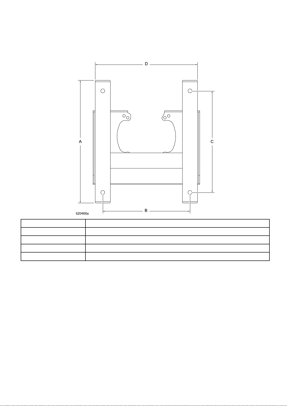
MountingHolePatterns
Mounting
Mounting Mounting
Stand
Stand Stand
Mount
Mount Mount
Hole
Hole Hole
Patterns
Patterns Patterns
Dimension
Dimension Dimension
A
B
C16.88in.(429mm)
D
Measurement
Measurement Measurement
19.88in.(505mm)
14.50in.(368mm)
17.00in.(432mm)
30 333389F
Page 31

MountingHolePatterns
Wall
Wall Wall
Mount
Mount Mount
Dimension
Dimension Dimension
A
B
C12.4in.(314mm)
D
E
F
G5.3in.(133mm)
H
J
K
L
M
N
P
Measurement
Measurement Measurement
17.8in.(451mm)
14.5in.(368mm)
9.0in.(229mm)
5.4in.(137mm)
7.4in.(187mm)
2.0in.(51mm)
1.0in.(25mm)
1.6in.(41mm)
2.7in.(69mm)
4.4in.(112mm)
Four0.562in.(14mm)diameterholesformountingtostand
Four0.438in.(11mm)diameterholesformountingtowall
333389F 31
Page 32

PerformanceCharts
0
400
(2.8, 28)
800
(5.5, 55)
1200
(8.3, 83)
1600
(10.0, 1 10)
2000
(13.8, 138)
2400
(16.6, 166)
2800
(19.3, 193)
3200
(22.1, 221)
3600
(24.8, 248)
4000
(27.6, 276)
4400
(30.3, 303)
0.0 0.1
(0.38)
0.2
(0.76)
0.3
(1.14)
0.4
(1.52)
0.5
(1.90)
0.6
(2.28)
0.7
(2.66)
0.8
(3.04)
3 8 14 21
0.9
(3.42)
1.0
(3.80)
A
B
C
D
E
F
Performance
Performance Performance
Charts
Charts Charts
Tondtheuidpressure(psi/bar/MPa)ataspecic
uidow(gpm/lpm)andpercentageofmaximum
force:
1.Locatethedesireduidowinthescaleatthe
bottomofthechart.
2.Followtheverticallineuptotheintersectionwith
theselectedpercentageofmaximumforce(see
Key
theKey Key
below).
3.Followlefttotheverticalscaletoreadtheuid
outletpressure.
Table
Table Table
2 22. ..E EE- --Flo Flo
Flo
DC
with
Dura
Flo
145
DC DC
with with
Dura Dura
- --Flo Flo
Lower
145 145
Lower Lower
Key
Key Key
NOTE:
NOTE: NOTE:
Performance
to totoPerformance Performance
Charts
Charts Charts
Thechartsshowthemotoroperatingat
100%,70%,and40%ofmaximumforce.These
valuesareapproximatelyequivalenttoanairmotor
operatingat100,70,and40psi.
A
B
40%singlephase
40%threephase
C70%singlephase
D
E
F
CYCLES
CYCLES CYCLES
PER
MINUTE
PER PER
MINUTE MINUTE
70%threephase
100%singlephase
100%threephase
FLUID
FLUID FLUID
PRESSURE:
PRESSURE: PRESSURE:
psi(bar,MPa)
FLUID
FLOW:
FLUID FLUID
FLOW: FLOW:
gpm(lpm)
32 333389F
Page 33

PerformanceCharts
0
400
(2.8, 28)
800
(5.5, 55)
1200
(8.3, 83)
1600
(10.0, 1 10)
2400
(16.6, 166)
2800
(19.3, 193)
3200
(22.1, 221)
2 8 15 21
0.0 0.1
(0.38)
0.2
(0.76)
0.3
(1.14)
0.4
(1.52)
0.5
(1.90)
0.6
(2.28)
0.7
(2.66)
0.8
(3.04)
0.9
(3.42)
1.0
(3.80)
2000
(13.8, 138)
A
B
C
D
E
F
0
400
(2.8, 28)
600
(4.1, 41)
200
(1.4, 14)
800
(5.5, 55)
1000
(6.9, 69)
1200
(8.3, 83)
1400
(9.7, 97)
1600
(10.0, 1 10)
1800
(12.4, 124)
2 8 15 21
0.0 0.2
(0.76)
0.4
(1.52)
0.6
(2.28)
0.8
(3.04)
1.0
(3.80)
1.2
(4.56)
2000
(13.8, 138)
2200
(15.2, 152)
2400
(16.6, 166)
2600
(17.9, 179)
A
B
C
D
E
F
Table
Table Table
FLUID
FLUID FLUID
PRESSURE:
PRESSURE: PRESSURE:
psi(bar,MPa)
3 33. ..E EE- --Flo Flo
Flo
DC
with
Dura
DC DC
with with
Flo/Xtreme
Dura Dura
- --Flo/Xtreme Flo/Xtreme
180
Lower
180 180
Lower Lower
CYCLES
CYCLES CYCLES
PER
MINUTE
PER PER
MINUTE MINUTE
FLUID
FLOW:
FLUID FLUID
FLOW: FLOW:
gpm(lpm)
Table
Table Table
FLUID
FLUID FLUID
PRESSURE:
PRESSURE: PRESSURE:
psi(bar,MPa)
Flo
DC
with
Dura
4 44. ..E EE- --Flo Flo
DC DC
with with
Flo/Xtreme
Dura Dura
- --Flo/Xtreme Flo/Xtreme
220
Lower
220 220
Lower Lower
CYCLES
CYCLES CYCLES
FLUID
FLUID FLUID
PER
PER PER
FLOW:
FLOW: FLOW:
MINUTE
MINUTE MINUTE
gpm(lpm)
333389F 33
Page 34

PerformanceCharts
0
200
(1.4, 14)
400
(2.8, 28)
600
(4.1, 41)
800
(5.5, 55)
1000
(6.9, 69)
1200
(8.3, 83)
1400
(9.7, 97)
1600
(10.0, 1 10)
1800
(12.4, 124)
0.0 1.2
(4.56)
1.4
(5.32)
2 8 15 21
0.2
(0.76)
0.4
(1.52)
0.6
(2.28)
0.8
(3.04)
1.0
(3.80)
A
B
C
D
E
F
Table
Table Table
FLUID
FLUID FLUID
PRESSURE:
PRESSURE: PRESSURE:
psi(bar,MPa)
5 55. ..E EE- --Flo Flo
Flo
DC
with
Dura
DC DC
with with
Flo/Xtreme
Dura Dura
- --Flo/Xtreme Flo/Xtreme
290
Lower
290 290
Lower Lower
CYCLES
CYCLES CYCLES
PER
MINUTE
PER PER
MINUTE MINUTE
FLUID
FLOW:
FLUID FLUID
FLOW: FLOW:
gpm(lpm)
34 333389F
Page 35

TechnicalSpecications
Technical
Technical Technical
Flo
DC
DC DC
Capacity
Capacity Capacity
Specication
Specication Specication
Inlet
Inlet Inlet
Outlet
Outlet Outlet
Pumps
Pumps Pumps
Fluid
Fluid Fluid
Fluid
Fluid Fluid
Potential
Potential Potential
ModelsESxCxx,ESxDxx,
ESxGxx,andESxHxx
Continuous
Continuous Continuous
Flow
Flow Flow
Requirements
Requirements Requirements
ModelsESxCxx,ESxDxx,
ESxGxx,andESxHxx
Inlet
Port
Inlet Inlet
Port Port
Temperature
Temperature Temperature
Data
Data Data
Size
Size Size
Size
Size Size
Parts
Parts Parts
E EE- --Flo Flo
Maximum
Maximum Maximum
Maximum
Maximum Maximum
Maximum
Maximum Maximum
ModelsESx3xx,ESx4xx,ESx7xx,
Maximum
Maximum Maximum
Maximum
Maximum Maximum
Power
Power Power
ModelsESx3xx,ESx4xx,ESx7xx,
Power
Power Power
Ambient
Ambient Ambient
Sound
Sound Sound
Oil
Oil Oil
Oil
Oil Oil
Weight
Weight Weight
Fluid
Fluid Fluid
Fluid
Fluid Fluid
Wetted
Wetted Wetted
Specications
Specications Specications
U.S.
U.S. U.S.
Working
Working Working
Working
Working Working
Size
Size Size
Pressure,
Pressure, Pressure,
ModelsES0xxx
ModelsES9xxx
ModelsES8xxx
ModelsES7xxx
Pressure,
Pressure, Pressure,
ModelsES0xxx
ModelsES9xxx
ModelsES8xxx
ModelsES7xxx
Fluid
Pressure
Fluid Fluid
Pressure Pressure
andESx8xx
Cycle
Cycle Cycle
andESx8xx
Range
Range Range
Single
Single Single
Three
Three Three
Rate
Rate Rate
Phase
Phase Phase
1520psi10.48MPa,104.8bar
2030psi14MPa,140bar
2430psi16.75MPa,167.5bar
3040psi20.96MPa,209.6bar
Phase
Phase Phase
1900psi13.1MPa,131bar
2540psi17.5MPa,175bar
3040psi21MPa,210bar
3800psi26.2MPa,262bar
436000/v(volumeoflowerincc)=psi3000/v(volumeoflowerincc)=bar
545000/v(volumeoflowerincc)=psi3750/v(volumeoflowerincc)=bar
20cpm
Maximumowisdeterminedbythesizeofthepumplower.
SeePerformanceCharts,page32.
200–250VAC,singlephase,50/60Hz,2.9kVA
380–480VAC,threephase,50/60Hz,3.0kVA
3/4–14npt(f)
32–104°F0–40°C
Lessthan70dB(A)
1.5quarts1.4liters
GracoPartNo.16W645ISO220silicone-freesyntheticgearoil
Pumppackage(motor,1000cclower,
stand,andtierods):220lb
1–1/2npt(f)
3/4npt(f)[145cc-180cc]
1npt(f)[220cc-290cc]
Seelowermanual.
Pumppackage(motor,1000cclower,
stand,andtierods):99.8kg
Metric
Metric Metric
California
California California
CALIFORNIA
CALIFORNIA CALIFORNIA
WARNING:
WARNING: WARNING:
333389F 35
RESIDENTS
RESIDENTS RESIDENTS
Proposition
Proposition Proposition
Cancerandreproductiveharm—www.P65warnings.ca.gov.
65
65 65
Page 36

Graco
Graco Graco
GracowarrantsallequipmentreferencedinthisdocumentwhichismanufacturedbyGracoand
bearingitsnametobefreefromdefectsinmaterialandworkmanshiponthedateofsaletotheoriginal
purchaserforuse.Withtheexceptionofanyspecial,extended,orlimitedwarrantypublishedby
Graco,Gracowill,foraperiodoftwelvemonthsfromthedateofsale,repairorreplaceanypartofthe
equipmentdeterminedbyGracotobedefective.Thiswarrantyappliesonlywhentheequipmentis
installed,operatedandmaintainedinaccordancewithGraco’swrittenrecommendations.
Thiswarrantydoesnotcover,andGracoshallnotbeliableforgeneralwearandtear,orany
malfunction,damageorwearcausedbyfaultyinstallation,misapplication,abrasion,corrosion,
inadequateorimpropermaintenance,negligence,accident,tampering,orsubstitutionofnon-Graco
componentparts.NorshallGracobeliableformalfunction,damageorwearcausedbythe
incompatibilityofGracoequipmentwithstructures,accessories,equipmentormaterialsnotsupplied
byGraco,ortheimproperdesign,manufacture,installation,operationormaintenanceofstructures,
accessories,equipmentormaterialsnotsuppliedbyGraco.
Thiswarrantyisconditionedupontheprepaidreturnoftheequipmentclaimedtobedefectivetoan
authorizedGracodistributorforvericationoftheclaimeddefect.Iftheclaimeddefectisveried,
Gracowillrepairorreplacefreeofchargeanydefectiveparts.Theequipmentwillbereturnedto
theoriginalpurchasertransportationprepaid.Ifinspectionoftheequipmentdoesnotdiscloseany
defectinmaterialorworkmanship,repairswillbemadeatareasonablecharge,whichchargesmay
includethecostsofparts,labor,andtransportation.
THIS
WARRANTY
THIS THIS
WARRANTY WARRANTY
OR
IMPLIED,
OR OR
IMPLIED, IMPLIED,
WARRANTY
WARRANTY WARRANTY
Graco’ssoleobligationandbuyer’ssoleremedyforanybreachofwarrantyshallbeassetforthabove.
Thebuyeragreesthatnootherremedy(including,butnotlimitedto,incidentalorconsequential
damagesforlostprots,lostsales,injurytopersonorproperty,oranyotherincidentalorconsequential
loss)shallbeavailable.Anyactionforbreachofwarrantymustbebroughtwithintwo(2)yearsof
thedateofsale.
GRACO
GRACO GRACO
MERCHANTABILITY
MERCHANTABILITY MERCHANTABILITY
ACCESSORIES,
ACCESSORIES, ACCESSORIES,
BY
BY BY
hose,etc.),aresubjecttothewarranty,ifany,oftheirmanufacturer.Gracowillprovidepurchaserwith
reasonableassistanceinmakinganyclaimforbreachofthesewarranties.
InnoeventwillGracobeliableforindirect,incidental,specialorconsequentialdamagesresulting
fromGracosupplyingequipmenthereunder,orthefurnishing,performance,oruseofanyproductsor
othergoodssoldhereto,whetherduetoabreachofcontract,breachofwarranty,thenegligenceof
Graco,orotherwise.
FORGRACOCANADACUSTOMERS
ThePartiesacknowledgethattheyhaverequiredthatthepresentdocument,aswellasalldocuments,
noticesandlegalproceedingsenteredinto,givenorinstitutedpursuantheretoorrelatingdirectlyor
indirectlyhereto,bedrawnupinEnglish.Lespartiesreconnaissentavoirconvenuquelarédaction
duprésentedocumentseraenAnglais,ainsiquetousdocuments,avisetprocéduresjudiciaires
exécutés,donnésouintentés,àlasuitedeouenrapport,directementouindirectement,avecles
procéduresconcernées.
MAKES
MAKES MAKES
GRACO.
GRACO. GRACO.
Standard
Standard Standard
IS
EXCLUSIVE,
IS IS
INCLUDING
INCLUDING INCLUDING
OF
OF OF
Theseitemssold,butnotmanufacturedbyGraco(suchaselectricmotors,switches,
EXCLUSIVE, EXCLUSIVE,
BUT
NOT
BUT BUT
FITNESS
FITNESS FITNESS
NO
WARRANTY,
NO NO
WARRANTY, WARRANTY,
AND
AND AND
EQUIPMENT,
EQUIPMENT, EQUIPMENT,
NOT NOT
FOR
FOR FOR
A AAPARTICULAR PARTICULAR
FITNESS
FITNESS FITNESS
MATERIALS
MATERIALS MATERIALS
Warranty
Warranty Warranty
AND
IS
IN
LIEU
OF
ANY
AND AND
IS IS
IN IN
LIEU LIEU
LIMITED
LIMITED LIMITED
PARTICULAR
AND
DISCLAIMS
AND AND
DISCLAIMS DISCLAIMS
FOR
FOR FOR
PARTICULAR
A AAPARTICULAR PARTICULAR
OR
OR OR
OF OF
TO
WARRANTY
TO TO
WARRANTY WARRANTY
PURPOSE.
PURPOSE. PURPOSE.
ALL
ALL ALL
COMPONENTS
COMPONENTS COMPONENTS
OTHER
ANY ANY
OTHER OTHER
IMPLIED
IMPLIED IMPLIED
PURPOSE,
PURPOSE, PURPOSE,
WARRANTIES,
WARRANTIES, WARRANTIES,
OF
MERCHANTABILITY
OF OF
MERCHANTABILITY MERCHANTABILITY
WARRANTIES
WARRANTIES WARRANTIES
IN
CONNECTION
IN IN
SOLD
SOLD SOLD
CONNECTION CONNECTION
BUT
BUT BUT
EXPRESS
EXPRESS EXPRESS
OR
OR OR
OF
OF OF
WITH
NOT
MANUFACTURED
NOT NOT
MANUFACTURED MANUFACTURED
WITH WITH
Graco
Graco Graco
ForthelatestinformationaboutGracoproducts,visitwww.graco.com.Forpatentinformation,see
www.graco.com/patents.
To
To To
Phone:
Phone: Phone:
Allwrittenandvisualdatacontainedinthisdocumentreectsthelatestproductinformationavailableatthetimeofpublication.
Information
Information Information
place
an
place place
an an
612-623-6921or ororToll Toll
GRACO
GRACO GRACO
order,
order, order,
contactyourGracoDistributororcalltoidentifythenearestdistributor.
Toll
Free:
Free: Free:
1-800-328-0211Fax: Fax:
Gracoreservestherighttomakechangesatanytimewithoutnotice.
OriginalInstructions.ThismanualcontainsEnglish,MM333389
Graco
International
International International
INC.
AND
INC. INC.
Copyright
Copyright Copyright
SUBSIDIARIES
AND AND
SUBSIDIARIES SUBSIDIARIES
2014,
Graco
2014, 2014,
Graco Graco
Graco Graco
Inc.
Inc. Inc.
Ofces:
Ofces: Ofces:
All
Graco
All All
Graco Graco
Headquarters:
Headquarters: Headquarters:
P.O.
• ••P.O. P.O.
manufacturing
manufacturing manufacturing
www.graco.com
RevisionF,May2020
Fax:
612-378-3505
Belgium,China,Japan,Korea
BOX
BOX BOX
Minneapolis
1441
MINNEAPOLIS,
1441 1441
• ••MINNEAPOLIS, MINNEAPOLIS,
locations
locations locations
MN
55440-1441
MN MN
55440-1441 55440-1441
are
registered
are are
registered registered
to totoISO ISO
• ••USA USA
ISO
9001.
9001. 9001.
USA
 Loading...