

Page 1
Installation - Parts
®
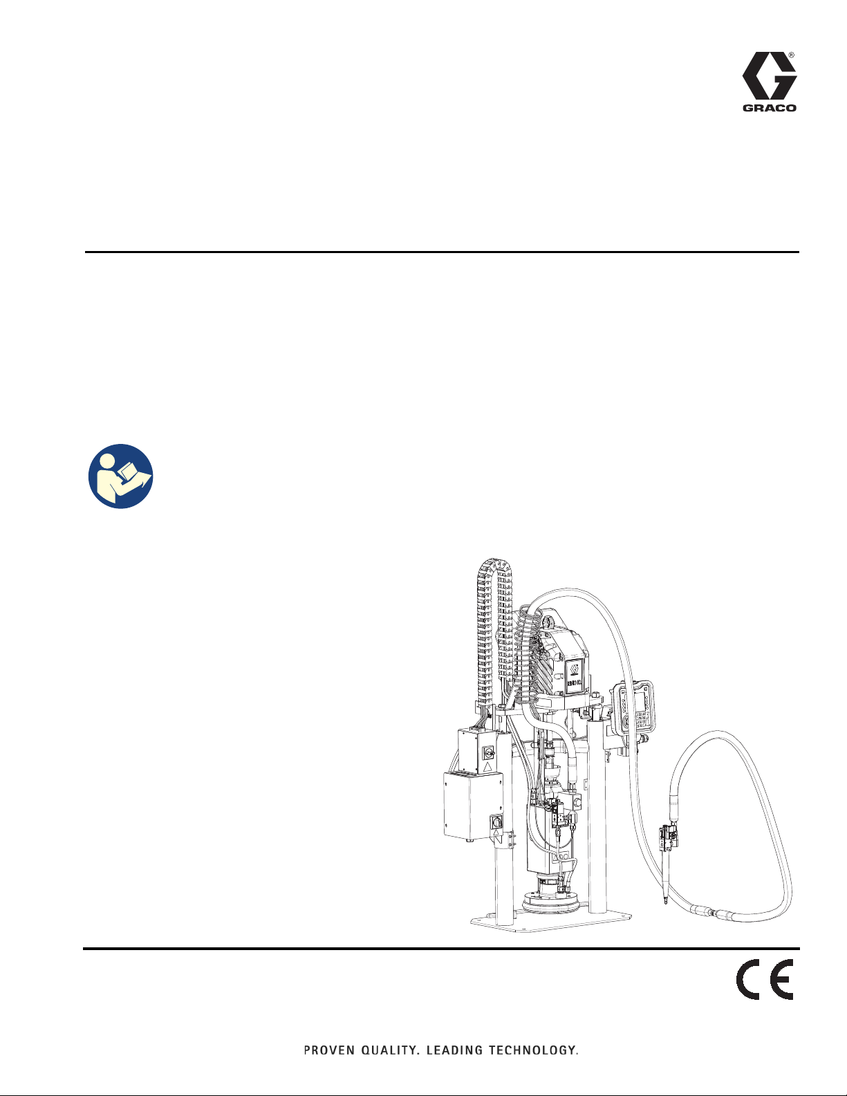
E-Flo
iQ Dispense
333586F
System
For dispensing and metering sealants, adhesives, and other medium to high viscosity
fluids. For professional use only.
Not approved for use in explosive atmospheres or hazardous (classified) locations.
See page 4 for system component information.
Important Safety Instructions
Read all warnings and instructions in this
manual and in related manuals before
using the equipment. Save all
instructions.
EN
Page 2

Contents
Related Manuals . . . . . . . . . . . . . . . . . . . . . . . . . . . . 3
Dispense System Configurator . . . . . . . . . . . . . . . . 4
Dispense System Components. . . . . . . . . . . . . . . . 5
iQ Ram Supply Units . . . . . . . . . . . . . . . . . . . . . . 5
iQ Dispense Valves . . . . . . . . . . . . . . . . . . . . . . . 6
Hose Options . . . . . . . . . . . . . . . . . . . . . . . . . . . . 6
Dispense System Pressure . . . . . . . . . . . . . . . . . . . 7
Warnings . . . . . . . . . . . . . . . . . . . . . . . . . . . . . . . . . . 8
Dispense System Component Identification . . . . 11
Single Ram . . . . . . . . . . . . . . . . . . . . . . . . . . . . 11
Tandem Ram . . . . . . . . . . . . . . . . . . . . . . . . . . . 12
Supply Unit Component Identification . . . . . . . . . 13
iQ Ram Supply Unit . . . . . . . . . . . . . . . . . . . . . . 13
Power Disconnect . . . . . . . . . . . . . . . . . . . . . . . 14
Integrated Air Controls (AG) . . . . . . . . . . . . . . . 15
Air Line Accessories . . . . . . . . . . . . . . . . . . . . . 15
Advanced Display Module (ADM) . . . . . . . . . . . 16
Platen (AD) Component Identification . . . . . . . . 17
Electric Driver Communication Connections . . . 18
Installing Tandem. . . . . . . . . . . . . . . . . . . . . . . . 20
Power Junction Box and Heat Control Box
Connections. . . . . . . . . . . . . . . . . . . . . . . . . 22
Installation. . . . . . . . . . . . . . . . . . . . . . . . . . . . . . . . 24
Location . . . . . . . . . . . . . . . . . . . . . . . . . . . . . . . 24
Grounding . . . . . . . . . . . . . . . . . . . . . . . . . . . . . 25
Power Requirements . . . . . . . . . . . . . . . . . . . . . 25
Connect Power . . . . . . . . . . . . . . . . . . . . . . . . . 25
Attach Drum Stops . . . . . . . . . . . . . . . . . . . . . . . 27
Install Vented Oil Cap Before Using Equipment. 28
Setup . . . . . . . . . . . . . . . . . . . . . . . . . . . . . . . . . . . . 29
Air Line Connections . . . . . . . . . . . . . . . . . . . . . 29
Hoses and Fittings . . . . . . . . . . . . . . . . . . . . . . . 29
Electrical Connections . . . . . . . . . . . . . . . . . . . . 31
Heat Connections (Hoses and Accessories) . . . 33
Wet Cup . . . . . . . . . . . . . . . . . . . . . . . . . . . . . . . 35
Hose Care Guidelines . . . . . . . . . . . . . . . . . . . . . . 36
Flush Before Using Equipment . . . . . . . . . . . . . 36
Check Resistance (Heated Systems) . . . . . . . . . . 37
Check Sensor Resistance . . . . . . . . . . . . . . . . . 37
Check Heater Resistance . . . . . . . . . . . . . . . . . 37
Pressure Relief Procedure . . . . . . . . . . . . . . . . . . . 39
Shutdown and Care of the Pump . . . . . . . . . . . . . 41
Change Drums . . . . . . . . . . . . . . . . . . . . . . . . . . 41
Maintenance . . . . . . . . . . . . . . . . . . . . . . . . . . . . . . 43
Driver Maintenance . . . . . . . . . . . . . . . . . . . . . . 43
Platen Maintenance . . . . . . . . . . . . . . . . . . . . . . 44
Recycling and Disposal . . . . . . . . . . . . . . . . . . . . . 45
End of Product Life . . . . . . . . . . . . . . . . . . . . . . . 45
Troubleshooting . . . . . . . . . . . . . . . . . . . . . . . . . . . 46
Supply Systems Troubleshooting . . . . . . . . . . . . 46
Heat Control Box Troubleshooting . . . . . . . . . . . 47
Platen Valve Kit Troubleshooting . . . . . . . . . . . . 47
Repair. . . . . . . . . . . . . . . . . . . . . . . . . . . . . . . . . . . . 48
Disconnect Pump from Platen . . . . . . . . . . . . . . 48
Connect Platen . . . . . . . . . . . . . . . . . . . . . . . . . . 50
Remove Wipers . . . . . . . . . . . . . . . . . . . . . . . . . 50
Install Wipers . . . . . . . . . . . . . . . . . . . . . . . . . . . 50
Remove Displacement Pump. . . . . . . . . . . . . . . 50
Install Displacement Pump . . . . . . . . . . . . . . . . . 52
Remove Driver . . . . . . . . . . . . . . . . . . . . . . . . . . 52
Install Driver . . . . . . . . . . . . . . . . . . . . . . . . . . . . 54
Ram Supply Unit Repair. . . . . . . . . . . . . . . . . . . 55
Replace Heat Control Box Electrical Component(s)
58
Replace Fuses in Harness (25R652) . . . . . . . . . 60
Parts . . . . . . . . . . . . . . . . . . . . . . . . . . . . . . . . . . . . . 61
D200s 6.5 in. Ram Supply Units. . . . . . . . . . . . . 61
D200 3 in. Ram Supply Units . . . . . . . . . . . . . . . 63
D60 3 in. Ram Supply Units . . . . . . . . . . . . . . . . 65
D200, D200s Pump Mounts for 55 Gallon (200 Liter)
Platen. . . . . . . . . . . . . . . . . . . . . . . . . . . . . . 67
D60 Pump Mount for 5 Gallon (20 Liter) Platen . 68
D200s Pump Mounts for 16 Gallon (60 Liter)
Platens . . . . . . . . . . . . . . . . . . . . . . . . . . . . . 69
Power Junction Box . . . . . . . . . . . . . . . . . . . . . . 70
Heat Control Box, 25R454 . . . . . . . . . . . . . . . . . 72
Cable Track, 26A935 . . . . . . . . . . . . . . . . . . . . . 73
55 Gallon Platen . . . . . . . . . . . . . . . . . . . . . . . . . 74
20 Liter (5 Gallon) Platens . . . . . . . . . . . . . . . . . 75
60 Liter (16 Gallon) Platens . . . . . . . . . . . . . . . . 77
Tandem Block, 25R848, 25R849 . . . . . . . . . . . . 79
2 333586F
Page 3

Related Manuals
Kits and Accessories . . . . . . . . . . . . . . . . . . . . . . . 80
System Kits and Accessories . . . . . . . . . . . . . . . 80
Drum Kits and Accessories . . . . . . . . . . . . . . . . 81
CAN Cables . . . . . . . . . . . . . . . . . . . . . . . . . . . . 81
I/O Integration Cable . . . . . . . . . . . . . . . . . . . . . 82
Integration Extension Cables . . . . . . . . . . . . . . . 82
Platen/Pump Heat Harness . . . . . . . . . . . . . . . . 82
Pressure Transducer Cables . . . . . . . . . . . . . . . 82
Solenoid Cables . . . . . . . . . . . . . . . . . . . . . . . . . 82
Heat Extension Cables . . . . . . . . . . . . . . . . . . . . 82
Cable Kits . . . . . . . . . . . . . . . . . . . . . . . . . . . . . . 83
Fitting Kits. . . . . . . . . . . . . . . . . . . . . . . . . . . . . . 83
Tandem Fitting Kits . . . . . . . . . . . . . . . . . . . . . . 83
Additional Accessories . . . . . . . . . . . . . . . . . . . . 83
Check-Mate 200 CS Pump Heater Kit, 25R450 . 84
Platen Heater Kit, 25R451 . . . . . . . . . . . . . . . . . 85
Communication Gateway Module (CGM) Kits . . 86
Platen Valve Kit, 25R452 . . . . . . . . . . . . . . . . . . 88
Platen Valve Kit, 25R453 . . . . . . . . . . . . . . . . . . 90
Dimensions . . . . . . . . . . . . . . . . . . . . . . . . . . . . . . . 93
Dimensions. . . . . . . . . . . . . . . . . . . . . . . . . . . . . 94
Pump Performance . . . . . . . . . . . . . . . . . . . . . . . . . 95
E-Flo iQ Dispense System Performance Chart . 96
Wiring Diagrams . . . . . . . . . . . . . . . . . . . . . . . . . . . 97
Technical Specifications . . . . . . . . . . . . . . . . . . . 102
California Proposition 65 . . . . . . . . . . . . . . . . . . . 103
Graco Standard Warranty . . . . . . . . . . . . . . . . . . 104
Graco Information . . . . . . . . . . . . . . . . . . . . . . . . 104
Related Manuals
Related Manuals in English:
Manual in
English
333587 E-Flo iQ Supply System Operation
312375
312468
312374 Air Controls Instructions-Parts
312491 Pump Fluid Purge Kit Instructions - Parts
312492 Drum Roller Kit Instructions
312493 Light Tower Kit Instructions
312494
406681 Platen Cover Kit
334048 EPDM Hose Wiper Kit Instructions - Parts
3A6321
3A6482
333585 iQ Dispense Valves, Instructions-Parts
3A1244 Graco Control Architecture Module
3A4241
Description
Check-Mate
Instructions-Parts
200 cc Check-Mate Displacement Pump
Repair Parts
Enclosed Wetcup Recirculation Kit
Instructions - Parts
ADM Token In-System Programming
Instructions
APD20 Advanced Precision Driver
Instructions
Hot Melt/Warm Melt Heated Hose
Instructions
®
Displacement Pumps
333586F 3
Page 4

Dispense System Configurator
Dispense System Configurator
The E-Flo iQ dispense system provides the flexibility to configure a complete system to meet your specific needs.
This includes offering multiple combinations of the following components:
• iQ Ram Supply Units
• iQ Dispense Valves
• Hoses and connectors
For dispense system component information, see Dispense System Components on page 5.
First,
Second
and
Third
Digit
EQC
E-Flo iQ
System
Fourth
Digit
Revision
Fifth
Digit Sixth Digit
Seventh
Digit
Platen
Single or
Tandem
S Single H Heated Y Yes
T Tan-
dem
Heat
Option
A Ambient
Valve
Option
Eighth Digit
Ram Supply Unit Options
Size
A 3 in.
B 3 in.
C 3 in.
D 3 in.
F 3 in.
G 3 in.
H 3 in.
J 3 in.
K 6.5 in.
M 6.5 in.
N 6.5 in.
P 6.5 in.
R 6.5 in.
T 6.5 in.
Drum
Size
20 L
(5 Gal) CS EPDM
20 L
(5 Gal) CS
20 L
(5 Gal) CM EPDM
20 L
(5 Gal) CM
200 L
(55 Gal) CS EPDM
200 L
(55 Gal) CS
200 L
(55 Gal) CM EPDM
200 L
(55 Gal) CM
200 L
(55 Gal) CS EPDM
200 L
(55 Gal) CS
200 L
(55 Gal) CM EPDM
200 L
(55 Gal) CM
60 L (16
Gal) CS PTFE
60 L (16
Gal) CS PTFE
Pump
Material
Seal
Material
Neo-
prene
Neo-
prene
Neo-
prene
Neo-
prene
Neo-
prene
Neo-
prene
Ninth Digit
Fieldbus
Option
A Ether-
Net/IP
B PROF-
INET
C PROFI-
BUS
D Devi-
ceNet
N None
Digits Ten
through
Seventeen
Hose
Options for
Tandem
Hoses (Dig-
its 10-13)
and Supply
Hoses (Dig-
its 14-17)
(See Hose
Options on
page 6)
Digits
Eighteen
through
Twenty Seven
Valve Options
(See the iQ
Dispense
Valves Instruc-
tions - Parts
manual for
valve model
options)
KEY:
CS = Carbon Steel Severe Duty
CM = Carbon Steel MaxLife
®
®
4 333586F
Page 5

Dispense System Components
Dispense System Components
NOTE: The Heated option for the E-Flo iQ system is for warm melt applications with a maximum temperature of 70° C
(158° F).
iQ Ram Supply Units
Check the identification plate (ID) on the back of the ram post near the Power Junction Box (AJ) for the seven-digit part
number of the iQ ram supply unit. Use the following matrix to define the construction of the unit, based on the seven digits.
For example, Part No. EZC2421 represents an electric supply unit (EZ), a carbon steel Check-Mate 200 Severe Duty dis-
placement pump (C2), a 3 in. ram (4), a 5-gallon platen with a neoprene seal (2), and an Advanced Display Module (ADM)
(2).
The digits in the following matrix do not correspond to the reference numbers in the Parts drawings and lists.
EZ C2 4
First
and
Second
Digit
EZ
(Electric
Supply
System)
Third and Fourth Digit Fifth Digit
Check-Mate Pump Options Ram Options
Pump
Size
Material
C1 200cc CS Ambient
C2 200cc CS Heated
C3 200cc CM Ambient
C4 200cc CM Heated
Heated/
Ambient
≤70° C
≤70° C 4 D60 3 in.
Name Size
1 D60 3 in.
2 D200 3 in.
3 D200s 6.5 in.
5 D200 3 in.
6 D200s 6.5 in.
Drum
Size Style
20 L
(5 Gal) Ambient 1
200 L
(55
Gal) Ambient 2
200 L
(55
Gal) Ambient 3
20 L
200 L
(55
Gal)
200 L
(55
Gal)
Heated
≤70° C 4
Heated
≤70° C 5
Heated
≤70° C 6
(5 Gal)
Sixth Digit
Platen and Seal Options
Platen
Size
(5 Gal) CST/AL Neoprene
(5 Gal) CST/AL Neoprene
(5 Gal) CST/AL EPDM
(5 Gal) CST/AL EPDM
200 L
200 L
200 L
7
200 L
8
9
A
Platen
Material
20 L
20 L
20 L
20 L
(55
Gal) AL Neoprene
(55
Gal) AL Neoprene
(55
Gal) AL EPDM
(55
Gal) AL EPDM
60 L
(16
Gal) CST/AL
60 L
(16
Gal) CST/AL
Material Wiper
22
Seventh
Digit
Interface
Options
Seal
PTFE
Coated
Nitrile
PTFE
Coated
Nitrile
Single
Single
Single
Single
Double
Double
Double
Double
Single
Single
Heated/
Ambient Interface
Ring Ambient 2ADM
Ring
Ring Ambient
Ring
Ring Ambient
Ring
Ring Ambient
Ring
Flat Ambient
Flat Heated
Heated
≤70° C 4 No ADM
Heated
≤70° C
Heated
≤70° C
Heated
≤70° C
KEY:
CS = Carbon Steel Severe Duty
CM = Carbon Steel MaxLife
CST/AL = Carbon Steel/Aluminum
AL = Aluminum
333586F 5
Page 6

Dispense System Components
iQ Dispense Valves
Check the identification plate on the valve for the ten-digit part number of the iQ dispense valve. Use the following
matrix to define the construction of the valve, based on the ten digits. For example, Part No. V25AB060BA
represents a valve (V) with 1/4” NPT inlet ports (25), NPT tip size (A), ball/seat type (B), 60 mm outlet block length
(060), solenoid (B), with no heat (A).
First
Digit
Second and
Third Digit
Fourth Digit Fifth Digit
Size Tip Size Type
Sixth, Seventh,
and Eighth Digit
Outlet Block
Length
Ninth Digit Tenth Digit
Action Heat
Valve
25
1/4 in. NPT
A 1/4 in. NPT B Ball/Seat 000 NA B
Mounted
A None
Solenoid
60 mm
V
C 0.6 mm S Snuff-Back 060
D 1.0 mm T Tip Seal 200
200 mm
D
*Remote
Solenoid
Block
B
Heated
≤
70° C
F 1.3 mm
G 1.7 mm
* Remote solenoid supplied by customer.
NOTE: Refer to the iQ Dispense Valves Instructions-Parts manual for additional information about iQ Dispense
Valves. See Related Manuals on page 3.
Hose Options
Working
Pressure
Temperature
Rating
4000 psi (28
MPa, 276 bar)
at -65° F - 400°
F (101° C - 204°
Part No. JIC Dash Size Length Heat
04 19M404 -10 (5/8 in, 15.9 mm) 6 ft Heated
05 19M405 -10 (5/8 in, 15.9 mm) 10 ft Heated
06 19M406 -10 (5/8 in, 15.9 mm) 15 ft Heated
07 19M407 -10 (5/8 in, 15.9 mm) 20 ft Heated
08 19M408 -10 (5/8 in, 15.9 mm) 25 ft Heated
11 19M411 -12 (3/4 in, 19.0 mm) 6 ft Heated
12 19M412 -12 (3/4 in, 19.0 mm) 10 ft Heated
13 19M413 -12 (3/4 in, 19.0 mm) 15 ft Heated
14 19M414 -12 (3/4 in, 19.0 mm) 20 ft Heated
15 19M415 -12 (3/4 in, 19.0 mm) 25 ft Heated
16 19M416 -16 (1 in, 25.4 mm) 6 ft Heated
17 19M417 -16 (1 in, 25.4 mm) 10 ft Heated
18 19M418 -16 (1 in, 25.4 mm) 15 ft Heated
19 19M419 -16 (1 in, 25.4 mm) 20 ft Heated
20 19M420 -16 (1 in, 25.4 mm) 25 ft Heated
Working
Pressure
Temperature
Rating
4000 psi (28
MPa, 276 bar)
at -65° F - 212°
F (-54° C - 100°
C)
3000 psi (21
MPa, 207 bar)
at 213° F - 400°
F (101° C - 204°
C)
Part No. JIC Dash Size Length Heat
65 17K265 -10 (5/8 in, 15.9 mm) 6 ft Ambient
66 17K266 -10 (5/8 in, 15.9 mm) 10 ft Ambient
67 17K267 -10 (5/8 in, 15.9 mm) 15 ft Ambient
68 17K268 -10 (5/8 in, 15.9 mm) 20 ft Ambient
69 17K269 -10 (5/8 in, 15.9 mm) 25 ft Ambient
72 17K272 -12 (3/4 in, 19.0 mm) 6 ft Ambient
73 17K273 -12 (3/4 in, 19.0 mm) 10 ft Ambient
74 17K274 -12 (3/4 in, 19.0 mm) 15 ft Ambient
75 17K275 -12 (3/4 in, 19.0 mm) 20 ft Ambient
76 17K276 -12 (3/4 in, 19.0 mm) 25 ft Ambient
77 17K277 -16 (1 in, 25.4 mm) 6 ft Ambient
78 17K278 -16 (1 in, 25.4 mm) 10 ft Ambient
79 17K279 -16 (1 in, 25.4 mm) 15 ft Ambient
80 17K280 -16 (1 in, 25.4 mm) 20 ft Ambient
81 17K281 -16 (1 in, 25.4 mm) 25 ft Ambient
00 No Hose N/A N/A N/A
C)
6 333586F
Page 7

Dispense System Pressure
Due to factors such as the dispensing system design,
the material being pumped, and the flow rate, the
dynamic pressure will not reach the rated working (stall)
pressure of the system.
Pump Working (Stall) Pressure Max Dynamic (Run) Pressure
Lower Size psi bar MPa psi bar MPa
Dispense System Pressure
Check-Mate
200CS/CM
4,000 290 29.0 3,905 269 26.9
333586F 7
Page 8
Warnings
DANGER
WARNING
Warnings
The following warnings are for the setup, use, grounding, maintenance, and repair of this equipment. The
exclamation point symbol alerts you to a general warning and the hazard symbols refer to procedure-specific risks.
When these symbols appear in the body of this manual or on warning labels, refer back to these Warnings.
Product-specific hazard symbols and warnings not covered in this section may appear throughout the body of this
manual where applicable.
SEVERE ELECTRIC SHOCK HAZARD
This equipment can be powered by more than 240 V. Contact with this voltage will cause death or
serious injury.
• Turn off and disconnect power at main switch before disconnecting any cables and before servicing
equipment.
• This equipment must be grounded. Connect only to grounded power source.
• All electrical wiring must be done by a qualified electrician and comply with all local codes and
regulations.
SKIN INJECTION HAZARD
High-pressure fluid from dispensing device, hose leaks, or ruptured components will pierce skin. This
may look like just a cut, but it is a serious injury that can result in amputation. Get immediate surgical
treatment.
• Do not point dispensing device at anyone or at any part of the body.
• Do not put your hand over the fluid outlet.
• Do not stop or deflect leaks with your hand, body, glove, or rag.
• Follow the Pressure Relief Procedure when you stop dispensing and before cleaning, checking, or
servicing equipment.
• Tighten all fluid connections before operating the equipment.
• Check hoses and couplings daily. Replace worn or damaged parts immediately.
8 333586F
Page 9
Warnings
WARNING
MOVING PARTS HAZARD
Moving parts can pinch, cut or amputate fingers and other body parts.
• Keep clear of moving parts.
• Do not operate equipment with protective guards or covers removed.
• Equipment can start without warning. Before checking, moving, or servicing equipment, follow the
Pressure Relief Procedure and disconnect all power sources.
FIRE AND EXPLOSION HAZARD
Flammable fumes, such as solvent and paint fumes, in work area can ignite or explode. Paint or
solvent flowing through the equipment can cause static sparking. To help prevent fire and explosion:
• Use equipment only in well-ventilated area.
• Eliminate all ignition sources; such as pilot lights, cigarettes, portable electric lamps, and plastic drop
cloths (potential static sparking).
• Ground all equipment in the work area. See Grounding instructions.
• Never spray or flush solvent at high pressure.
• Keep work area free of debris, including solvent, rags and gasoline.
• Do not plug or unplug power cords, or turn power or light switches on or off when flammable fumes
are present.
• Use only grounded hoses.
• Hold gun firmly to side of grounded pail when triggering into pail. Do not use pail liners unless they
are anti-static or conductive.
• Stop operation immediately if static sparking occurs or you feel a shock. Do not use equipment until
you identify and correct the problem.
• Keep a working fire extinguisher in the work area.
333586F 9
Page 10
Warnings
WARNING
EQUIPMENT MISUSE HAZARD
Misuse can cause death or serious injury.
• Do not operate the unit when fatigued or under the influence of drugs or alcohol.
• Do not exceed the maximum working pressure or temperature rating of the lowest rated system
component. See Technical Specifications in all equipment manuals.
• Use fluids and solvents that are compatible with equipment wetted parts. See Technical
Specifications in all equipment manuals. Read fluid and solvent manufacturer’s warnings. For
complete information about your material, request Safety Data Sheets (SDSs) from distributor or
retailer.
• Turn off all equipment and follow the Pressure Relief Procedure when equipment is not in use.
• Check equipment daily. Repair or replace worn or damaged parts immediately with genuine
manufacturer’s replacement parts only.
• Do not alter or modify equipment. Alterations or modifications may void agency approvals and create
safety hazards.
• Make sure all equipment is rated and approved for the environment in which you are using it.
• Use equipment only for its intended purpose. Call your distributor for information.
• Route hoses and cables away from traffic areas, sharp edges, moving parts, and hot surfaces.
• Do not kink or over bend hoses or use hoses to pull equipment.
• Keep children and animals away from work area.
• Comply with all applicable safety regulations.
SPLATTER HAZARD
Hot or toxic fluid can cause serious injury if splashed in the eyes or on skin. During blow off of platen,
splatter may occur.
• Use minimum air pressure when removing platen from drum.
TOXIC FLUID OR FUMES HAZARD
Toxic fluids or fumes can cause serious injury or death if splashed in the eyes or on skin, inhaled, or
swallowed.
• Read Safety Data Sheets (SDSs) to know the specific hazards of the fluids you are using.
• Store hazardous fluid in approved containers, and dispose of it according to applicable guidelines.
BURN HAZARD
Equipment surfaces and fluid that is heated can become very hot during operation. To avoid severe
burns:
• Do not touch hot fluid or equipment.
PERSONAL PROTECTIVE EQUIPMENT
Wear appropriate protective equipment when in the work area to help prevent serious injury, including
eye injury, hearing loss, inhalation of toxic fumes, and burns. Protective equipment includes but is not
limited to:
• Protective eyewear, and hearing protection.
• Respirators, protective clothing, and gloves as recommended by the fluid and solvent manufacturer.
10 333586F
Page 11
Dispense System Component Identification
A
B
C
D
E
H
G
J
F
*Circular
Electrical
Connection
*Square
Electrical
Connection
*Circular
Electrical
Connection
*Square
Electrical
Connection
Dispense System Component Identification
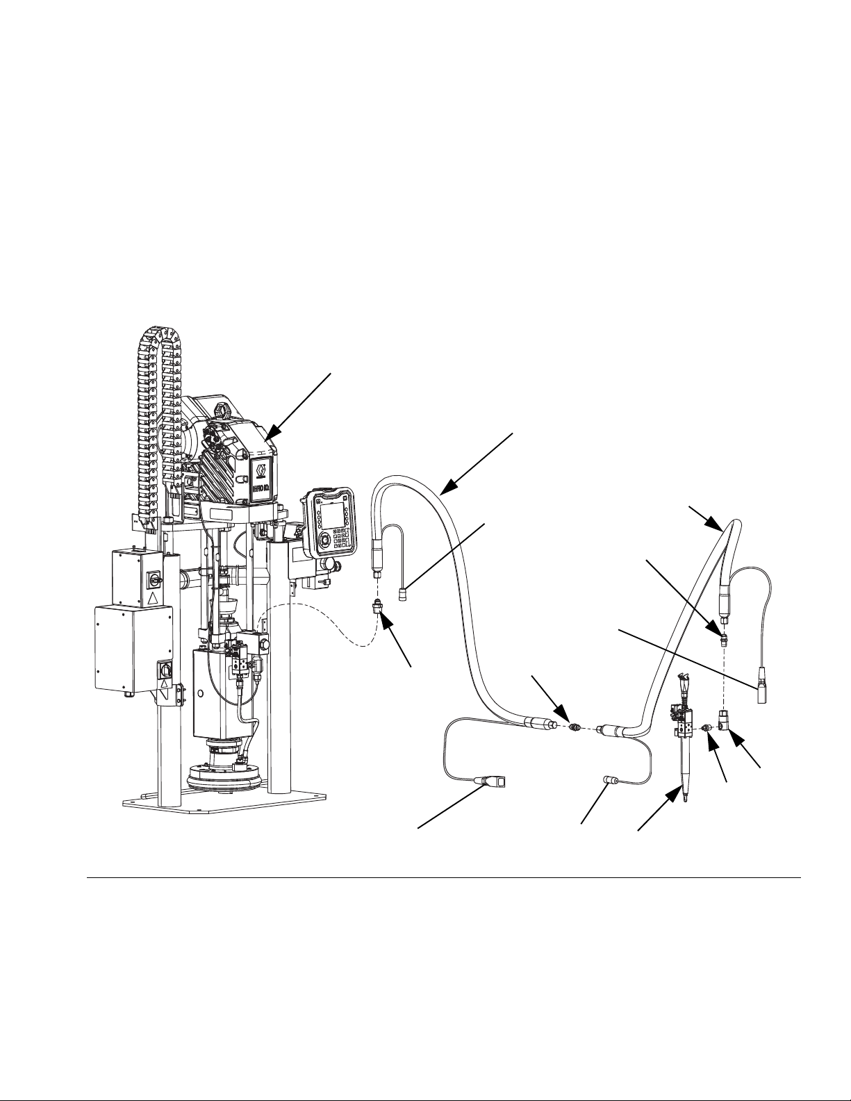
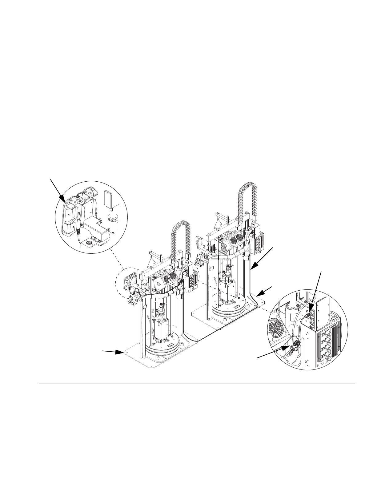
Single Ram
NOTE: FIG. 1 shows a typical E-Flo iQ dispense system
installation with a single iQ ram supply unit, hoses,
connectors, and an iQ dispense valve. Some
installations may require only one hose depending on
the needs of the system.
FIG. 1: Single E-Flo iQ Dispense System
Key:
A iQ Ram Supply Unit
B iQ Dispense Valve
C Supply Hose 1
D Supply Hose 2
E Ram Supply System to Supply Hose 1 Fitting
F Supply Hose 1 to Supply Hose 2 Fitting
G Supply Hose 2 to Swivel Fitting
H Swivel Fitting
J Swivel to Valve Fitting
* Applies to heated hoses only.
333586F 11
Page 12
Dispense System Component Identification
A
B
M
D
F
G
H
J
K
L
R
C
E
N
P
*Circular
Electrical
Connection
*Square
Electrical
Connection
*Circular
Electrical
Connection
*Square
Electrical
Connection
*Circular
Electrical
Connection
S
S
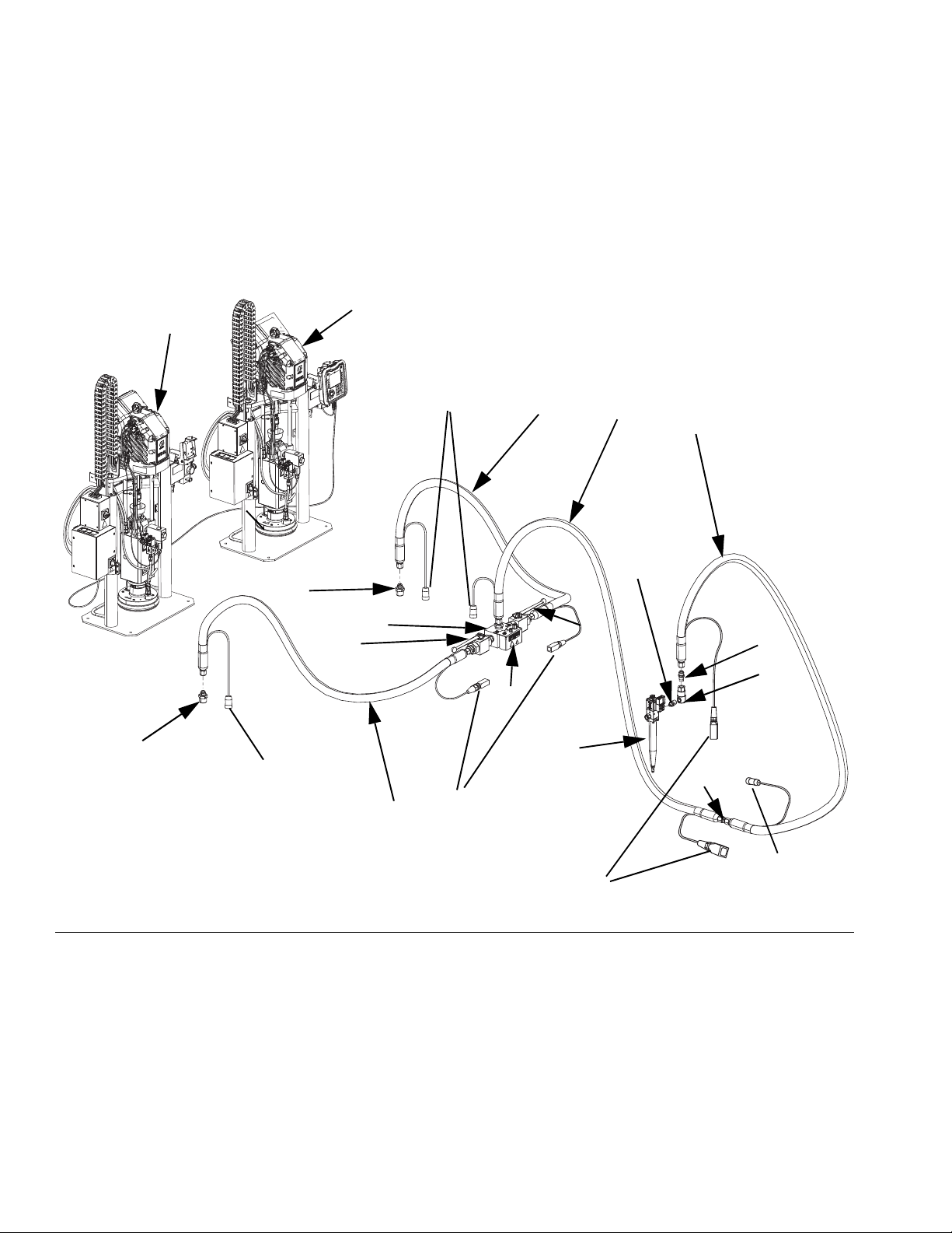
Tandem Ram
Tandem E-Flo iQ Dispense Systems consist of two
rams connected using a 3-way block with ball valves,
and are controlled by a single ADM.Tandem E-Flo iQ
Dispense Systems operate identically to Single E-Flo iQ
Dispense Systems, with the added benefit of dispensing
from the second ram when the first drum is empty.
NOTE: F
IG
. 2 shows a typical E-Flo iQ dispense system
installation with a tandem iQ ram supply unit, hoses,
connectors, and an iQ dispense valve. Some
installations may not require Supply Hose 2 (D) to iQ
Dispense Valve (B) depending on the needs of the
system.
FIG. 2: Tandem E-Flo iQ Dispense System
Key:
A iQ Ram Supply Unit 1
B iQ Dispense Valve
C Supply Hose 1
D Supply Hose 2
E Tandem Block to Supply Hose 1 Fitting
F Supply Hose 1 to Supply Hose 2 Fitting
G Supply Hose 2 to Swivel Fitting
H Swivel Fitting
J Swivel to Valve Fitting
K iQ Ram Supply Unit 2
L Tandem Hose 1
M Tandem Hose 2
N Ram Supply Unit 1 to Tandem Hose 1 Fitting
P Ram Supply Unit 2 to Tandem Hose 2 Fitting
R Tandem Block
S Ball Valve
* Applies to heated hoses only.
12 333586F
Page 13

Supply Unit Component Identification
Lift Locations
Ambient System
AZ
Heated System
AZ
AK
AU
AT
AS
AA
AB
AV
AF
AG
AR
AN
AM
AD
AJ
AK
*AX
AL
*ZA
AZ
AY
AC
AE
AW
ZB
AH
ZC
Supply Unit Component Identification
iQ Ram Supply Unit
D200 3 in. Dual Post
NOTICE
Always lift the iQ Ram Supply Unit at the proper lift
locations (see F
IG
. 3). Do not lift in any other way.
Failure to lift at the proper lift locations can result in
damage to the Supply System.
FIG. 3: iQ Ram Supply Unit
Key:
AA Ram Assembly
AB Electric Driver
AC Displacement Pump
AD Platen (see F
AE Fluid Check Valve
AF Advanced Display Module (ADM)
AG Integrated Air Controls (see F
AH Platen Bleed Port
AJ Power Junction Box
AK Power Junction Box Switch
AL Platen Lift Rod
AM Pump Bleed Valve
AN Wet Cup
333586F 13
IG
. 7)
IG
. 5)
AR Air Line (not supplied)
AS Air Line Drain Valve (not supplied)
AT Air Filter (not supplied)
AU Bleed Type Air Shutoff Valve (required) (not supplied)
AV Level Sensors
AW Outlet Pressure Transducer
AX *Heat Control Box
AY Platen Valve Kit (optional)
AZ Disconnect Switch (see Power Disconnect on page 14)
ZA *Pump Heater
ZB Recirculation Hose
ZC Pump Relief Valve
* Parts on heated systems only.
Page 14
Supply Unit Component Identification
AK
AZ
Heated System
AZ
Ambient System
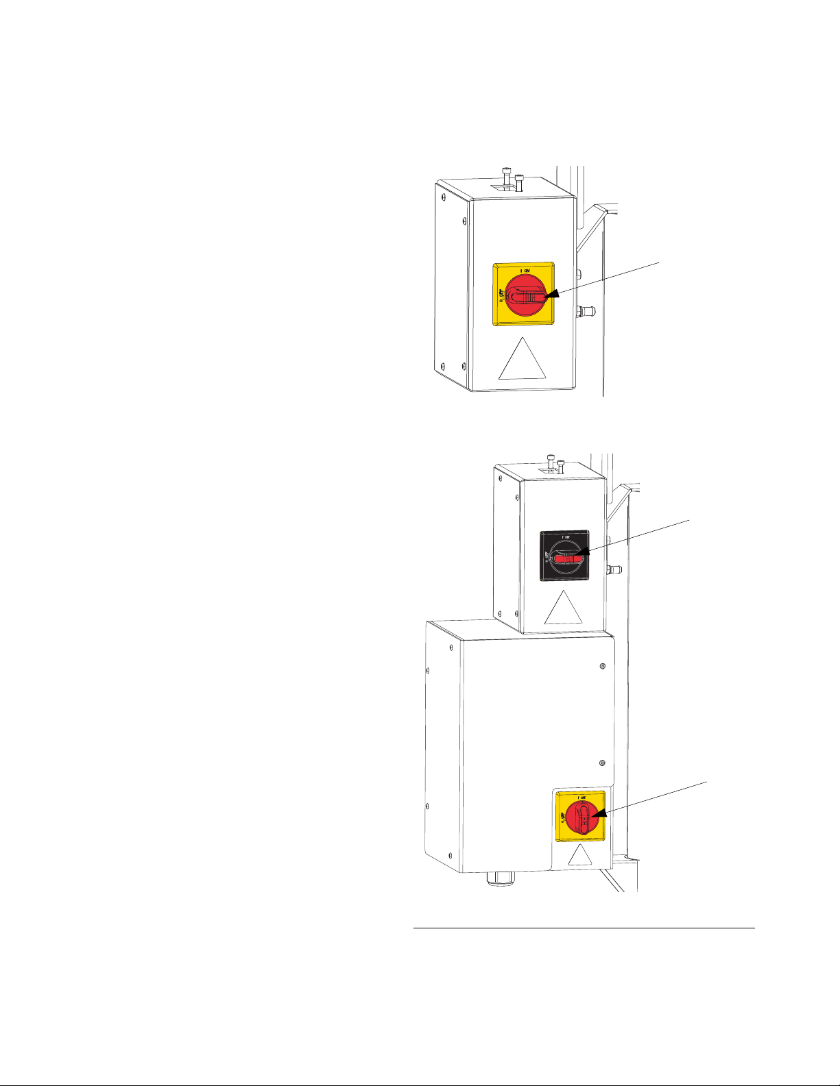
Power Disconnect
Every E-Flo iQ Dispense System has a red and yellow
Disconnect Switch which shuts off power to the entire
system. The location of the switch is different for
ambient and heated systems. See F
On ambient systems, the Disconnect Switch (AZ) is
located on the Power Junction Box (AJ).
On heated systems, the Disconnect Switch (AZ) is
located on the Heat Control Box (AX). Heated systems
also have a red and black Power junction Box Switch
(AK) located on the Power Junction Box (AJ). The
Power Junction Box Switch (AK) removes power to
everything EXCEPT heat. The Disconnect Switch (AZ)
removes power to the entire system, including heat.
IG
. 4.
F
IG
. 4. Power Disconnect
14 333586F
Page 15
Supply Unit Component Identification
BA
BB
BC
BE
BD
BD
1/4 NPT
Plug
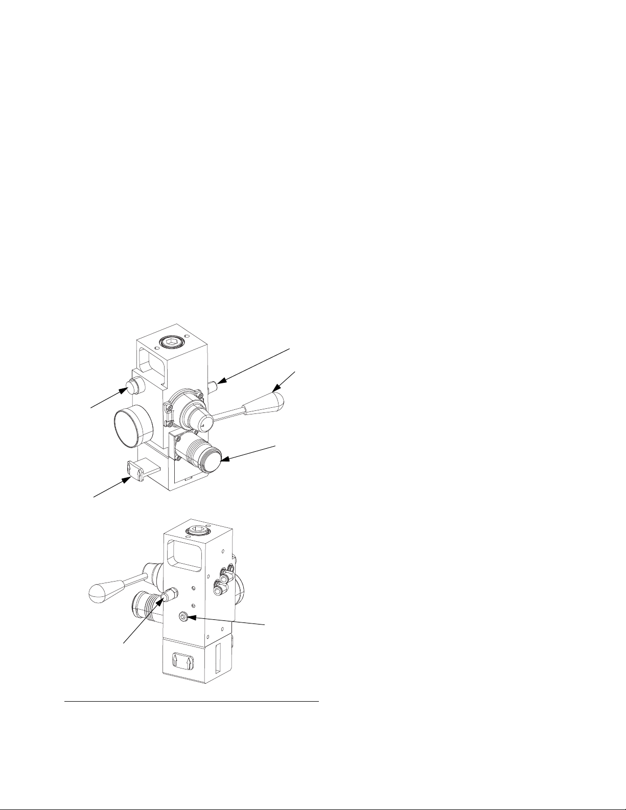
Integrated Air Controls (AG)
The integrated air controls include:
• Main Air Slider Valve (BA): turns the air on and off
to the iQ Ram Supply Unit. When closed, the valve
relieves all air pressure downstream.
• Ram Air Regulator (BB): controls the Ram Assem-
bly up and down pressure and the blowoff pressure.
• Ram Director Valve (BC): controls the Ram
Assembly direction.
• Exhaust Port with Muffler (BD)
• Blowoff Button (BE): turns the air on and off to
push the Platen (AD) out of an empty drum.
Air Line Accessories
See FIG. 3.
• Air Line Drain Valve (AS) (not supplied): removes
condensed water from air line.
• Air Line Filter (AT) (not supplied): removes harmful dirt and moisture from the compressed air sup-
ply.
• Second Bleed-type Air Valve (AU) (required) (not
supplied): isolates the Air Line accessories for ser-
vicing. Locate upstream from all other Air Line
accessories.
F
IG
. 5. Integrated Air Controls
333586F 15
Page 16
Supply Unit Component Identification
CA
CB
CC
CD
CE
CF
CG
CH
CP
CK
CN
CM
CL
CJ
CR
CS
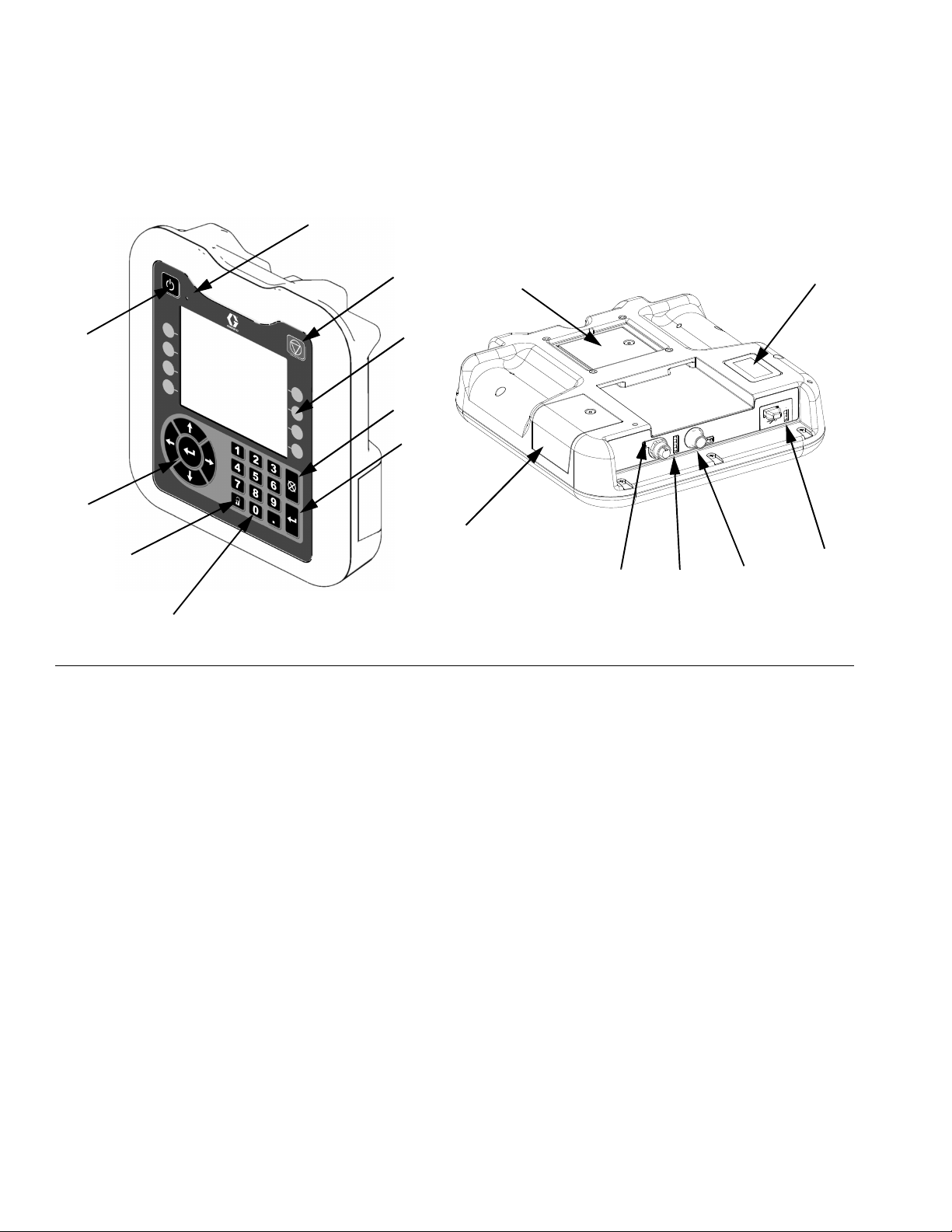
Advanced Display Module (ADM)
Front and Rear Views
FIG. 6: ADM Component Identification
Key:
CA Startup/Shutdown
Starts up or shuts down the system. Toggles
between Active and Inactive system.
CB System Status Indicator LED
CC Pump Soft Stop
Stops all pump processes and disables the pump.
Also stops all heating processes and disables the
heat. This is not a safety or emergency stop.
CD Soft Keys
Defined by the icon on the screen next to the soft
key. Performs the specific operation for that icon
when pressed.
CE Cancel
Cancels a selection or number entry while in the
process of entering a number or making a selection.
Cancels the pump processes. Exits a screen
without saving changes.
CF Enter
Select to update a field, accept a selection or value,
acknowledge an event, enter a screen, and toggle
selected items.
CG Lock/Setup
Toggles between Run screens and the iQ Menu.
CH Directional Keypad
Navigate within a screen or to a new screen.
CJ Numeric Keypad
Input numeric values.
CK Part Number Identification Label
CL USB Interface
CM CAN Cable Connection
Power and communication.
CN Module Status LEDs
Visual indicators to show the status of the ADM.
CP Token Access Cover
Access cover for blue software token.
CR Battery Access Cover
CS Light Tower Connection
NOTE: If using a tandem system, the ADM is only
included with the iQ Ram Supply Unit 1 (A).
16 333586F
Page 17
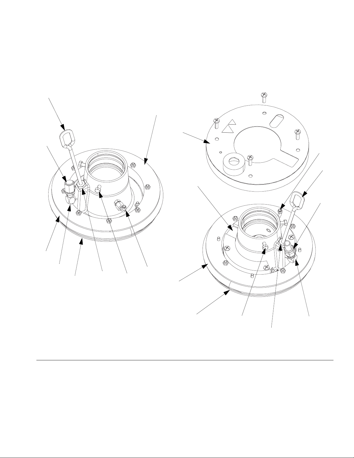
Platen (AD) Component Identification
Ambient
Heated
EF
EC
EB
EJ
ED
EH
EA
EA
EB
EF
EJ
EH
EG
EG
ED
EL
EL
EM
EM
Supply Unit Component Identification
F
IG
. 7
Key:
EA Plate
EB Wiper
EC Heater Cover
ED Cap Screws
EF Bleed Stick
EG Bleed Port
EH Air Assist Body Check Valve
EJ Wiper Plate (under wiper)
333586F 17
EK O-ring Seal (not shown)
EL Platen Valve Port
EM Platen Valve Cap
Page 18
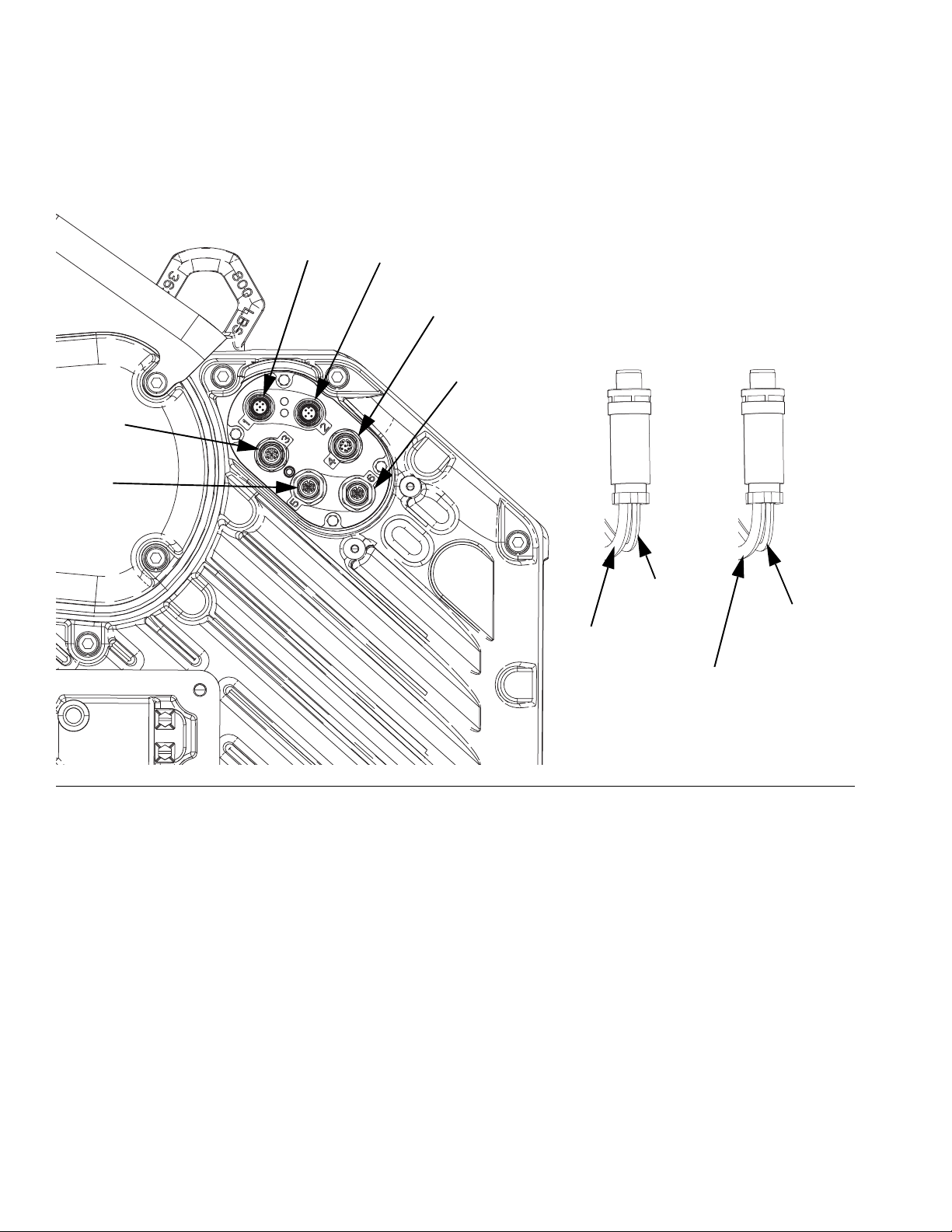
Supply Unit Component Identification
Port 1
Port 2
Port 4
Port 6
Port 3
Port 5
Port 3 Connection
Port 4 Connection
Pump
Solenoid
Valve
(M8 4 pin)
Power
Junction Box
Port C3
(M12 5 pin)
Power
Junction Box
Port C4
(M12 8 pin)
Dispense
Valve
Solenoid
(M8 4 pin)
Electric Driver Communication Connections
Single Ram
F
IG
. 8
Key:
Port 1 Connects to port C1 on the Power Junction Box.
Port 2 Connects to port C2 on the Power Junction Box.
Port 3 Connects to port C3 on the Power Junction Box
(M12 5 pin), and to the pump solenoid valve (M8 4
pin).
Port 4 Connects to port C4 on the Power Junction Box
(M12 8 pin), and to the dispense valve solenoid (M8
4 pin).
Port 5 Connects to the pump pressure transducer.
Port 6 Connects to the valve pressure transducer.
18 333586F
Page 19
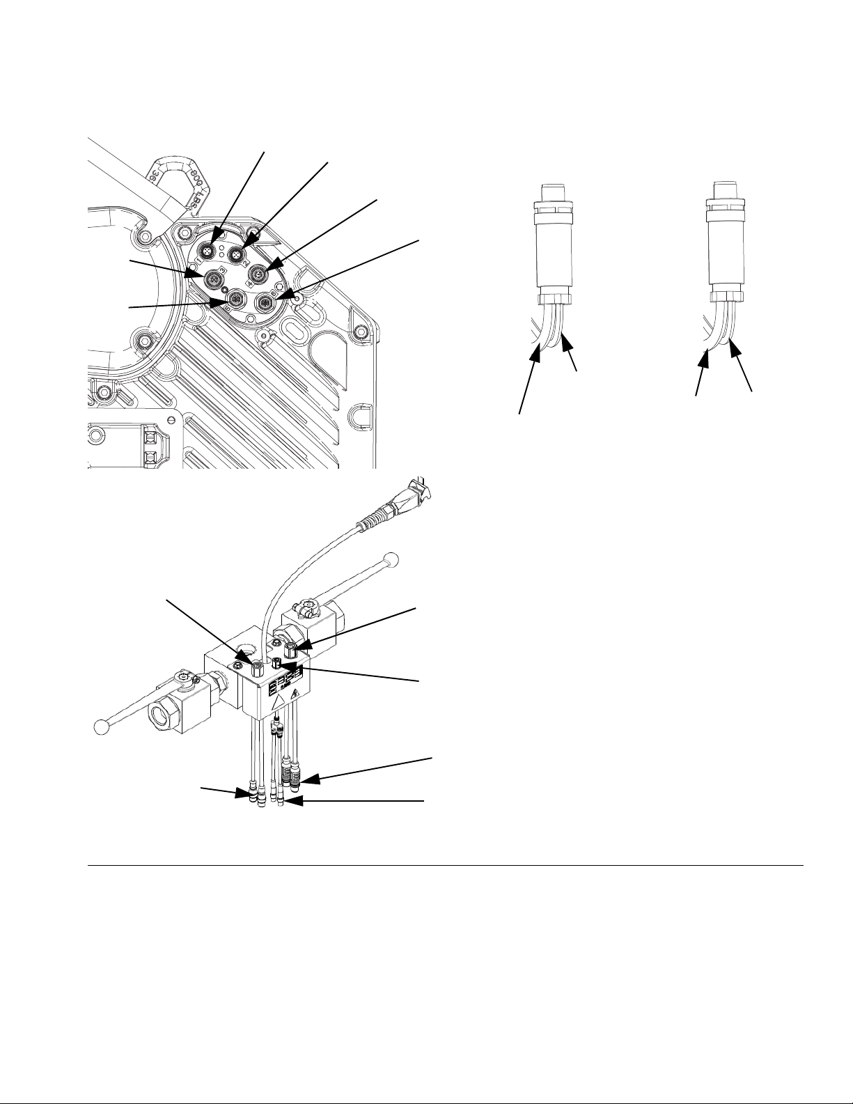
Tandem Ram
Port 1
Port 4
Port 6
Port 3
Port 5
Port 3 Connection
Port 4 Connection
Pump
Solenoid
Valve
(M8 4 pin)
Power
Junction Box
Port C3
(M12 5 pin)
Tandem
Block
discrete
Robot
connection
Splitter
Tandem
Block
dispense
valve
Solenoid
Splitter
(M8 4 pin)
Tandem Block
To Robot
Controller
To Dispense
Valve Solenoid
To Driver Port 6
To Power Junction Box Port C4
(Robot Controller Splitter M12 8 pin)
To Power Junction Box Port C4
(Solenoid Splitter M8 4 pin)
Pressure
Transducer
Port 2
Supply Unit Component Identification
FIG. 9
333586F 19
Page 20
Supply Unit Component Identification
A
K
ADM
C1
Cable from Tandem Kit
Splitter from Tandem Block
Installing Tandem
1. Remove cable from port C1 on ram 1 and plug into
female end of splitter. Splitter is included in tandem
kit.
2. Install 0.4 m cable (121226) included in tandem kit
from male end of splitter to part C1 on ram 1.
3. Install 5.0 m cable (124003) included in the tandem
kit, from male end of splitter and connect to part C1
of ram 2.
4. Use zip ties included in kit to secure cables to ram
frame. See F
NOTE: Ram 1 includes ADM, ram 2 has no ADM.
IG
. 10 for cable routing.
F
IG
. 10: Communication Connections
Key:
Port 1 Connects to port C1 on the Power Junction Box.
Port 2 Connects to port C2 on the Power Junction Box.
Port 3 Connects to port C3 on the Power Junction Box (M12 5 pin), and to the platen valve solenoid (M8 4 pin).
Port 4 Connects to port C4 on the Power Junction Box, and to the Tandem Block (R) solenoid splitter (M8 4 pin).
Port 5 Connects to the pump pressure transducer.
Port 6 Connects to the valve pressure transducer splitter on the Tandem Block (R).
20 333586F
Page 21
Low Level Sensor Kit, 25R439
LL
EL
SP
NOTE: The Low Level Sensor Kit is an optional
accessory for Single Ram Systems, and a required
accessory for Tandem Ram Systems.
To install the Low Level Sensor:
1. Turn the Disconnect Switch (AZ) OFF.
2. Disconnect cable from the empty level sensor (EL).
3. Mount the low level sensor (LL) on the mounting
bracket.
4. Connect the splitter cable (SP) to the previously
disconnected cable.
5. Connect the splitter cable (SP) lead labeled EMPTY
to the empty level sensor (EL).
6. Connect the splitter cable (SP) lead labeled LOW to
the low level sensor (LL).
Supply Unit Component Identification
7. Raise/lower the low level sensor (LL) to the desired
position to activate the sensor.
8. See the E-Flo iQ Supply System Operation manual
to set up the low level sensor.
333586F 21
Page 22
Supply Unit Component Identification
C1
C2
C3
C4
Ambient
Heated
C1
C2
C3
C4
C5
C6
C7
AK
AZ
AZ
AMZ
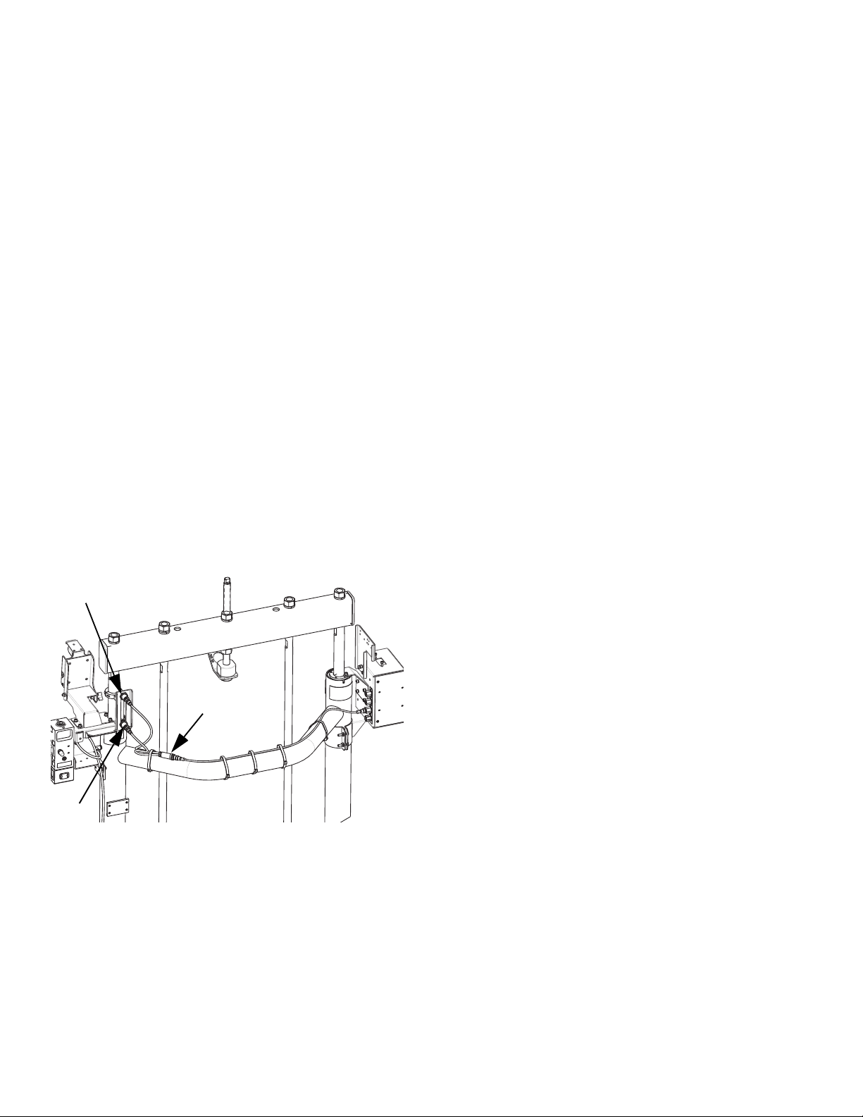
Power Junction Box and Heat Control Box Connections
Single Ram
FIG. 11
Key:
C1 GCA CAN Port (to ADM)
C2 GCA CAN Port (to CGM)
C3 Low and Empty Level Sensor Input
C4 Discrete Integration Cable
22 333586F
C5 Heated Hose/Accessory Connec-
tion
C6 Heated Pump Connection
C7 Heated Platen Connection
AK Power Junction Box Switch
AZ Disconnect Switch
AMZ Auto Multi-Zone
Page 23
Tandem Ram
C1
C2
C3
C4
Ambient
Heated
C1
C2
C3
C4
C5
C6
C7
AMZ
Supply Unit Component Identification
FIG. 12
iQ Ram Supply Unit 1
Key:
C1 GCA CAN Port (to ADM splitter cable on Tandem Block
(R) using the supplied CAN cable (124003))
C2 GCA CAN Port (to CGM)
C3 Low and Empty Level Sensor Input
C4 Discrete Integration Cable (to robot splitter cable on tan-
dem block)
C5 Port 1, Port 2, Port 3: Heated Hose/Accessory Connec-
tion
C6 (Port 4) Pump
C7 (Port 5) Platen
AK Power Junction Box Switch (same as Single Ram on
page 22)
AZ Disconnect Switch (same as Single Ram on page 22)
AMZ Auto Multi-Zone
iQ Ram Supply Unit 2
Key:
C1 GCA CAN Port (to ADM splitter cable on Tandem Block
C2 GCA CAN Port (to CGM)
C3 Low and Empty Level Sensor Input
C4 Discrete Integration Cable (to robot splitter cable on TanC5 Port 1, Port 2, Port 3: Heated Hose/Accessory Connec-
C6 (Port 4) Pump
C7 (Port 5) Platen
AK Power Junction Box Switch (same as Single Ram on
AZ Disconnect Switch (same as Single Ram on page 22)
AMZ Auto Multi-Zone
(R) using the supplied CAN cable (124003))
dem Block (R))
tion
page 22)
333586F 23
Page 24

Installation
Installation
All electrical wiring must be done by a qualified electrician and comply with all local codes and regula-
tions.
The E-Flo iQ Dispense System is shipped in five to six
containers:
1. iQ Ram Supply Unit that includes the fully
assembled ram, electric driver, and pump.
2. iQ Dispense Valve
3. Hoses (shipped in one or two containers depending
on the number of hoses used)
4. Fittings
5. Cables and a pressure transducer
The E-Flo iQ Tandem Dispense System is shipped in
ten to eleven containers:
1. iQ Ram Supply Unit that includes the fully
assembled ram, electric driver, and pump.
2. Second iQ Ram Supply Unit that includes the fully
assembled ram, electric driver, and pump.
3. iQ Dispense Valve
4. Hoses (shipped in three or four containers
depending on the number of hoses used)
5. Fittings
6. Tandem fittings
7. Cables and a pressure transducer
8. Tandem Kit
Location
Remove the iQ Ram Supply Unit from its crate. Attach a
lifting sling at the proper lift locations (see F
of the pallet using a crane or a forklift.
To properly locate and anchor the iQ Ram Supply Unit
(A), see Dimensions on page 93.
NOTICE
Always lift the iQ Ram Supply Unit at the proper lift
locations (see F
Failure to lift at the proper lift locations can result in
damage to the system.
NOTE: The lift ring on the Driver (AB) is only to be used
for replacing the Driver. Do not use it to lift the entire
system.
Position the Ram Assembly (AA) so the Driver (AB),
Power Junction Box Switch (AK) and/or Disconnect
Switch (AZ), Integrated Air Controls (AG), and ADM
(AF) are easily accessible. Ensure that there is enough
space overhead for the Ram Assembly to raise fully.
Use the holes in the Ram Assembly base as a guide
and drill holes for 1/2 in. (13 mm) anchors.
Ensure that the Ram Assembly base is level in all direc-
tions. If necessary, level the base using metal shims.
Secure the base to the floor using 1/2 in. (13 mm)
anchors that are long enough to prevent the Ram
Assembly from tipping.
IG
. 3). Do not lift in any other way.
IG
. 3). Lift off
NOTE: Additional items including CGM and accessories
may be shipped in additional containers.
This section describes how to install and set up the
E-Flo iQ system and make all the necessary component
connections.
24 333586F
Page 25
Installation
LQ
LQ
Grounding
The equipment must be grounded to reduce the risk
of static sparking and electric shock. Electric or static
sparking can cause fumes to ignite or explode.
Improper grounding can cause electric shock.
Grounding provides an escape wire for the electric
current.
Ram Assembly: the iQ Ram Supply Unit is grounded
through the incoming power cord. See Connect Power
on page 25.
Air and fluid hoses: use only electrically conductive
hoses with a maximum of 500 ft. (150 m) combined
hose length to ensure grounding continuity. Check the
electrical resistance of the hoses. If the total resistance
to ground exceeds 29 megaohms, replace the hose
immediately.
Air compressor: follow the manufacturer’s recommen-
dations.
Power Requirements
Each iQ Ram Supply Unit requires a dedicated circuit
protected with a circuit breaker.
For Ambient Systems:
Voltage Phase Hz Current
200-240 VAC 1 50/60 20 A
For Heated Systems:
Voltage Phase Hz Current
200-240 VAC 1 50/60 60 A
200-240 VAC 3 50/60 38 A
380-420 VAC 3 (YN) 50/60 38 A
Connect Power
NOTICE
To avoid equipment damage, route and secure a
power cord that is long enough to allow the full range
of movement for the Ram.
Dispense valve: see the iQ Dispense Valves Instruc-
tions-Parts manual for grounding information.
Fluid supply container: follow local code.
Solvent pails used when flushing: follow local code.
Use only conductive metal pails, placed on a grounded
surface. Do not place the pail on a non-conductive sur-
face, such as paper or cardboard, which interrupts the
grounding continuity.
To maintain grounding continuity when flushing or
relieving pressure: hold a metal part of the dispense
valve firmly to the side of a grounded metal pail, then
trigger the valve.
Ambient Systems
1. Turn the Disconnect Switch (AZ) OFF.
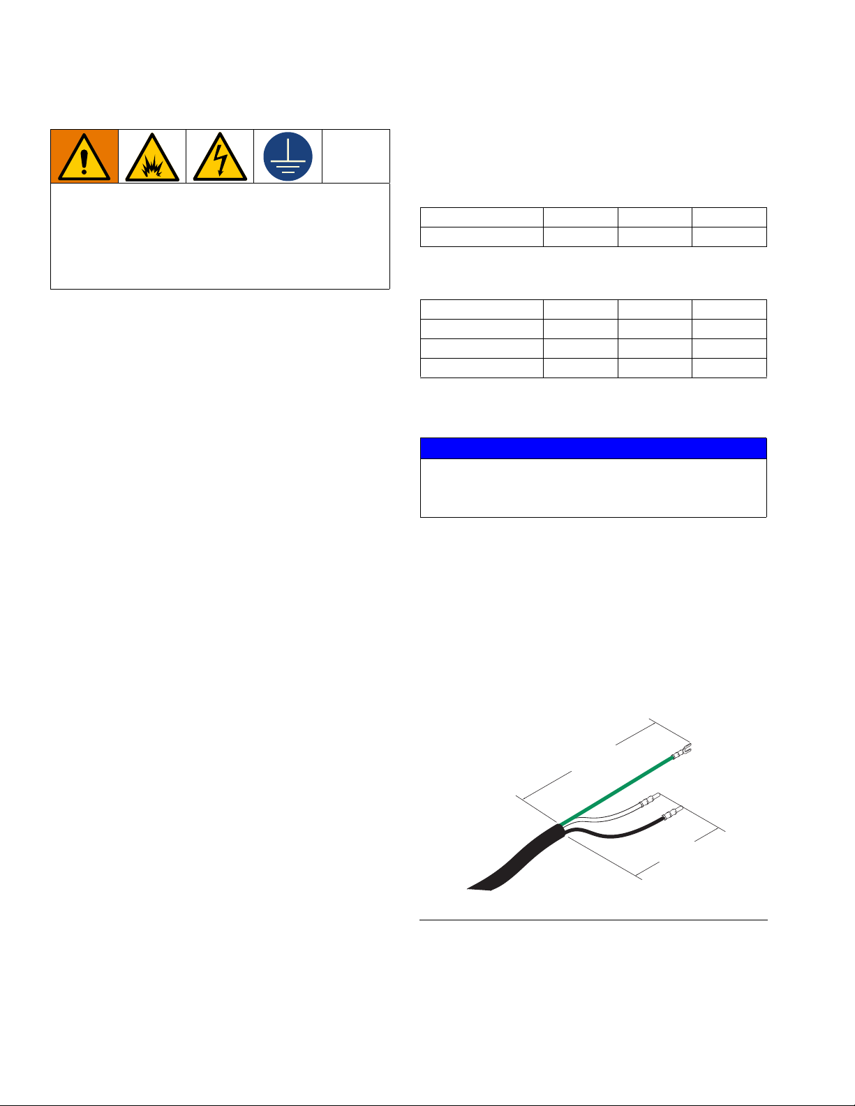
2. Cut power cord wires to the following lengths:
• Ground wire - 6.5 inches (16.5 cm)
• Power wires - 3.0 inches (7.6 cm)
• Add ferrules as necessary. See F
FIG. 13: Power Cord
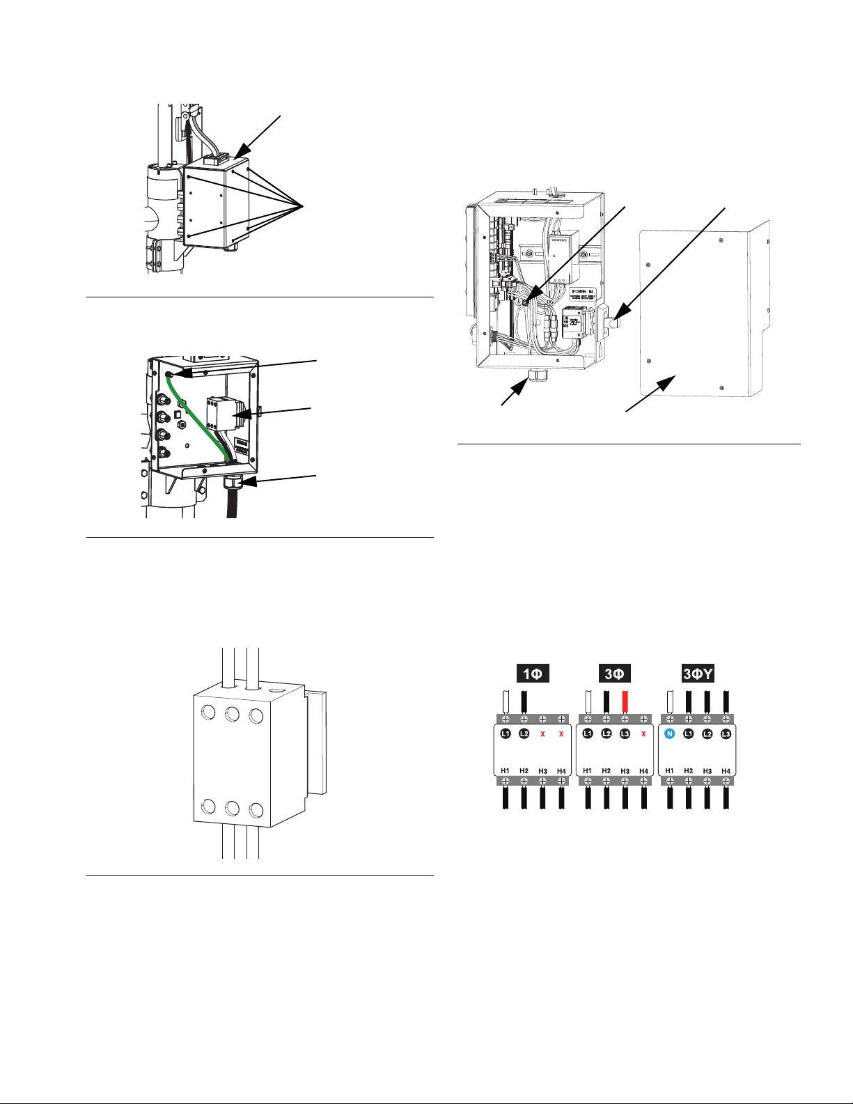
3. Remove the six screws holding the cover of the
Power Junction Box (AJ), then remove the Power
Junction Box cover.
IG
. 13.
333586F 25
Page 26
Installation
Screws
AJ
Ground Lug
Cord Grip
Disconnect Switch
Terminal Block
1L1
3L2
5L3
2T1
4T2
6T3
SR
350
GS
AZ
ti31214a
FIG. 14: Remove the Power Junction Box Cover
4. Insert the power cord through the cord grip and into
the Power Junction Box (AJ).
Heated Systems
1. Turn the Heat Control Box Disconnect Switch (AZ)
OFF.
FIG. 17
2. Loosen the screws and remove the cover (350) on
the Heat Control Box (AX).
FIG. 15: Power Connection
5. Attach the ground wire to the ground lug inside the
Power Junction Box (AJ).
6. Refer to F
IG
. 16 and connect the wires from the
power cord into terminals 4T2 and 6T3 on the Dis-
connect Switch terminal block.
3. Insert the electrical cord through the electrical
enclosure strain relief bushing (SR).
4. Attach insulated ferrules to the end of each wire.
5. Connect the ground wire to the ground stud (GS).
6. Connect power wires to the Heat Control Box Dis-
connect Switch (AZ) as shown below.
NOTE: Use a flat-head or Pozidriv screwdriver to tighten
the terminals to 7-10 in-lb (0.8-1.1 N•m).
FIG. 16: Disconnect Switch Terminal Block
NOTE: Use a flat-head or Pozidriv screwdriver to tighten
7. Tighten the strain relief bushing (SR) around the
electrical cord.
the terminals to 7-10 in-lb (0.8-1.1 N•m).
7. Tighten the cord grip to securely hold the power
cord to the Power Junction Box (AJ).
8. Replace the Power Junction Box cover and secure it
with the six screws that were removed in step 2.
26 333586F
8. Close the Heat Control Box door (350).
Page 27
Attach Drum Stops
Drum Stops
Capscrews
55 gal (200 L)
30 gal (115 L)
8 gal (30 L)
5 gal (20 L)
D200 and D200s Base D60 Base
8 gal (30 L)
5 gal (20 L)
60 gal (16 L)
16 gal (60 L)
The iQ Ram Supply Units are shipped with drum stops
in place to help position the drum on the Ram Assembly
(AA). For replacement parts, order Kit 255477. The kit
includes 2 each of capscrews, lock washers (not
shown), and drum stops.
Installation
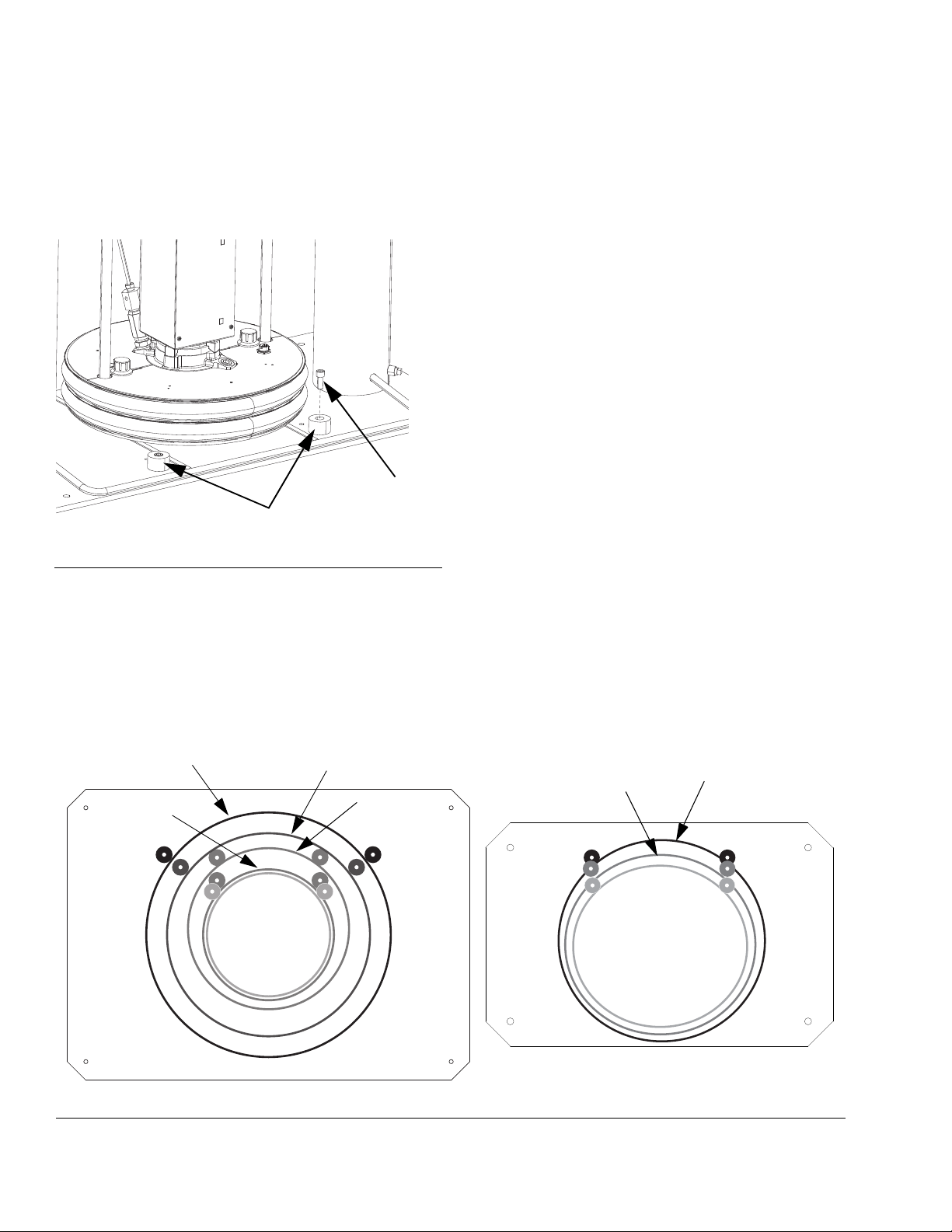
FIG. 18: Drum Stop Installation
1. Locate the correct set of mounting holes on the
Ram Assembly base. See F
2. Using the capscrews and lock washers, attach the
drum stops to the Ram Assembly base.
IG
. 19.
FIG. 19: Ram Base
333586F 27
Page 28
Installation
Unvented
Cap
Vented Cap
Sight Glass
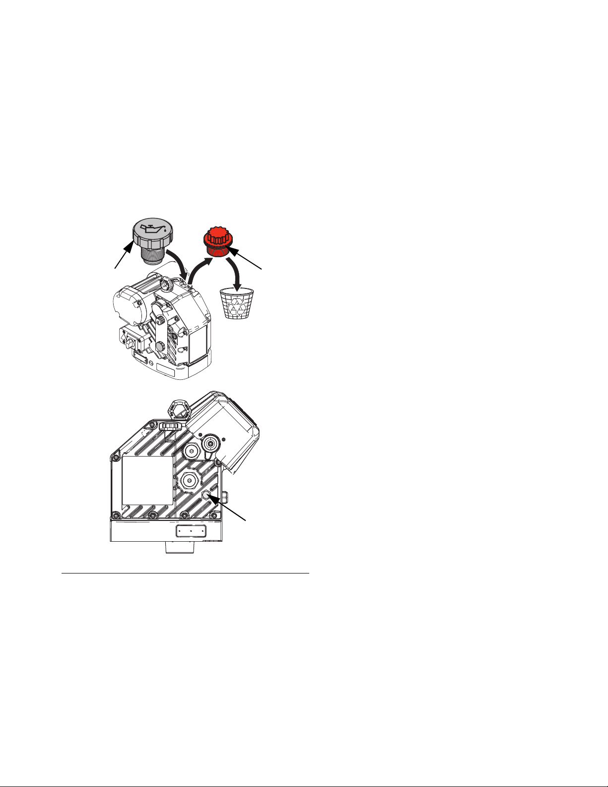
Install Vented Oil Cap Before Using Equipment.
The Driver gear-box is shipped from the factory
pre-filled with oil. The temporary unvented cap prevents
oil leaks during shipment. Replace this temporary cap
with the vented oil cap supplied with the equipment
before use.
NOTE: Prior to use, check oil level. Oil level should be
half way up the sight glass.
28 333586F
FIG. 20: Unvented and Vented Oil Caps
Page 29
Setup
A, K
E, N, P
Fluid
Check
Valve
Setup
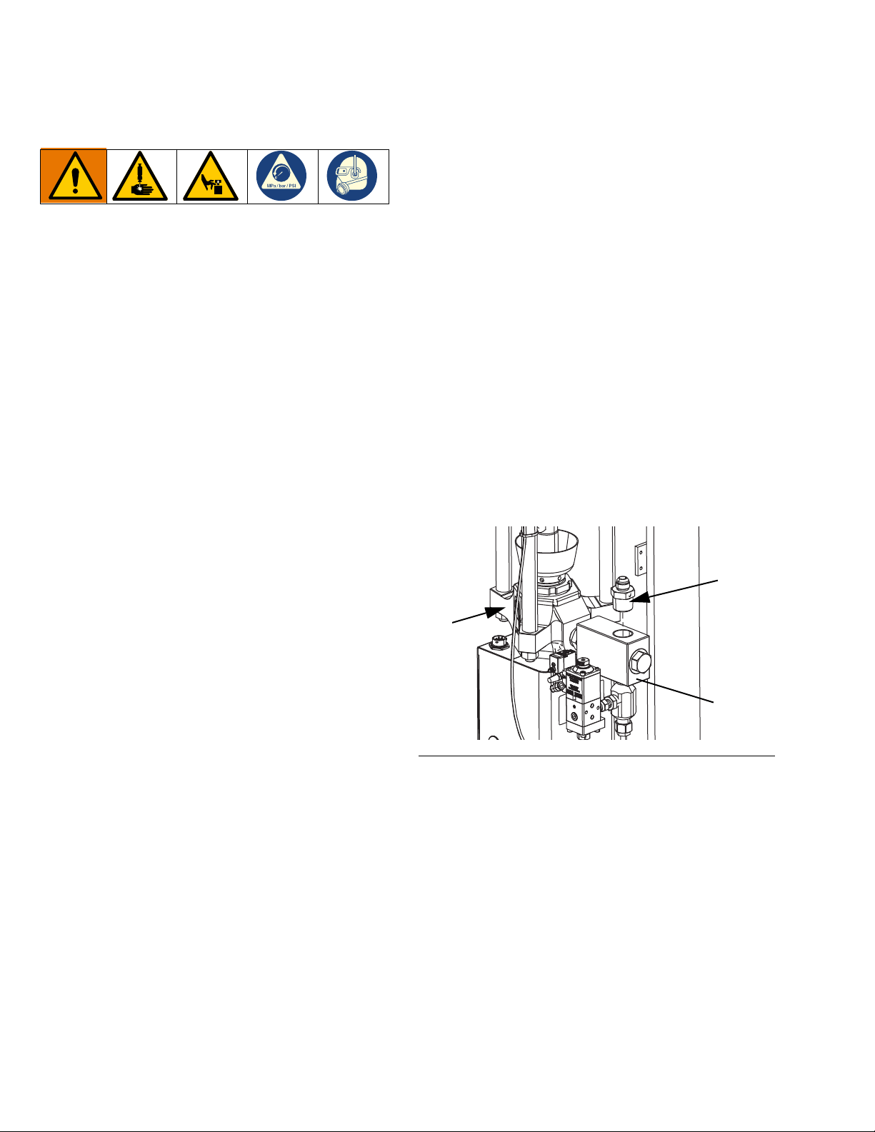
2. If using a Single iQ Ram Supply System, connect
the Ram Supply System to Supply Hose 1 Fitting
(E) to the fluid check valve (AE) on the iQ Ram
Supply Unit (A).
Remove the iQ Dispense Valve (B) from its packaging.
Refer to the iQ Dispense Valves Instructions-Parts
manual included with the valve for information about
installing the valve. See Related Manuals on page 3.
Air Line Connections
Refer to FIG. 3 on page 13 for a typical installation.
Attach the Air Line (AR) (not supplied) to the bottom of
the Integrated Air Control (AG) at the 3/4 in. NPT con-
nection.
NOTE: Be sure all components are adequately sized
and pressure rated to meet the system’s requirements.
Hoses and Fittings
NOTE: A number of options are available for fittings,
hoses, and cables for the E-Flo iQ Dispense System.
Yours may differ in appearance from those shown in
F
IG
. 1 on page 11 and FIG. 2 on page 12. However, the
steps for making the connections are the same.
3. If using a Tandem iQ Ram Supply System:
a. Connect the Ram Supply Unit 1 to Tandem
Hose 1 Fitting (N) to the fluid check valve (AE)
on iQ Ram Supply Unit 1 (A).
b. Connect the Ram Supply Unit 2 to Tandem
Hose 2 Fitting (P) to the fluid check valve (AE)
on the iQ Ram Supply Unit 2 (K).
NOTE: The Recirculation Hose (ZB) should not be
connected to the to the platen fitting at this time. See the
E-Flo iQ Dispense System Operation manual for more
information on when to connect the Recirculation Hose
(ZB).
See F
IG
. 1 on page 11 and FIG. 2 on page 12 to connect
the hoses and fittings to the iQ Ram Supply Unit(s) (A,
K) and the Dispense Valve (B).
NOTE: Do not connect any hoses if flushing the pump
for the first time. See the E-Flo iQ Dispense System
Operation manual for instructions on flushing the pump
and connecting hoses.
NOTE: To ensure the best crossover performance with
an E-Flo iQ Tandem System, Tandem Hose 1 and
Tandem Hose 2 must be the same inner diameter and
length.
1. Follow the Pressure Relief Procedure on page 39.
333586F 29
FIG. 21
4. If using a Single iQ Ram Supply System, connect
Supply Hose 1 (C) to the Ram Supply System to
Supply Hose 1 Fitting (E) as shown in F
F
IG
. 22.
5. If using a Tandem iQ Ram Supply System:
a. Connect Tandem Hose 1 (L) to the Ram Supply
Unit 1 to Tandem Hose 1 Fitting (N) as shown in
F
IG
. 2 and FIG. 22.
b. Connect Tandem Hose 2 (M) to the Ram
Supply Unit 2 to Tandem Hose 2 Fitting (P) as
IG
shown in F
. 2 and FIG. 22.
IG
. 1 and
Page 30
Setup
E, N, P
L, M, C
C
R
L
M
F
C
D
G
H
J
B
J
B
H
c. Connect Tandem Hose 1 (L) and Tandem Hose
2 (M) from the supply system to the Tandem
Block (R). See F
IG
. 23.
d. Connect Supply Hose 1 (C) to the Tandem
IG
Block (R). See F
. 23.
FIG. 22
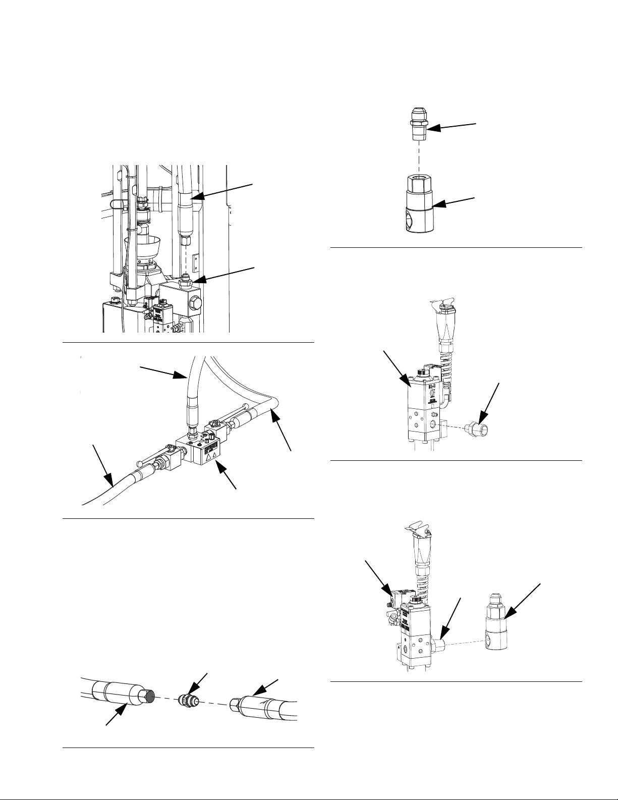
7. Connect the Supply Hose 2 to Swivel Fitting (G) to
the Swivel Fitting (H).
FIG. 25
8. Connect the Swivel to Valve Fitting (J) to the
Dispense Valve (B) as shown in F
IG
. 26.
FIG. 26
9. Connect the Swivel Fitting (H) to the Dispense
Valve (B) at the Swivel to Valve Fitting (J) that was
connected in step 8.
FIG. 23
6. If you are using two supply hoses (C and D), use the
Supply Hose 1 to Supply Hose 2 Fitting (F) to
connect Supply Hose 1 (C) to Supply Hose 2 (D).
See F
IG
. 24.
NOTE: If using heated hoses, make sure the electrical
connections of each hose are oriented correctly, with
the circular electrical connector facing the Ram. See
F
IG
. 1 on page 11 for proper hose orientation on the
system.
FIG. 27
FIG. 24
30 333586F
Page 31

Setup
B
H
G
D
PC
PC
Pressure Transducer Cable
Connection (XX).
Discrete Robot Cable
Connection (SS).
Dispense Valve solenoid
Cable Connection (YY).
M12 8 pin Discrete Robot
Splitter (RR).
M8 4 Pin Dispense Valve
Solenoid Splitter (TT) to
Splitter Attached to Port 4
on Electric Drive (AB) on
Ram 1 and Ram 2. Pin
M12 5 Pin Pressure
Transducer Splitter
Cable (ZZ) to Port 6
on Electric Drive
(AB) on Ram 1 and
Ram 2..
R
(NN)
10. If two hoses are used, connect Supply Hose 2 (D) to
the Swivel Fitting (H) on the Dispense Valve (B)
using the Supply Hose 2 to Swivel Fitting (G). If only
one hose is used, connect Supply Hose 1 (C) to the
Swivel Fitting (H) on the Dispense Valve (B) using
the Supply Hose 2 to Swivel Fitting (G).
FIG. 28
11. Tighten all fittings until secure.
12. Connect the Air Line (AR) (not supplied) to the air
fitting (FT) on the dispense valve solenoid. See the
iQ Dispense Valves Instructions-Parts manual. See
F
IG
. 31.
Electrical Connections
Pressure Transducer
1. If using a Single iQ Ram Supply System, connect
the pressure transducer cable (PC) from dispense
valve (B) to Port 6 on the Electric Driver (AB). See
Electric Driver Communication Connections for
Single Rams on page 18.
2. If using a Tandem iQ Ram Supply System:
a. Connect the Pressure Transducer Cable (PC)
from the Dispense Valve (B) to the Tandem
Block Valve Pressure Transducer Splitter. See
F
IG
. 29.
b. Connect one male end of the M12 5 pin
Pressure Transducer Splitter cable (ZZ) on the
Tandem Block (R) to Port 6 on the Electric
Driver (AB) on Ram 1. The second male end
goes to Port 6 on Ram 2. See Electric Driver
Communication Connections for Tandem
Rams on page 19.
FIG. 29
333586F 31
Page 32

Setup
Solenoid Valve
Solenoid Valve
Cable
B
PA
PC
FT
VD
NN
VC
Dispense Valve Solenoid
3. If using a Single iQ Ram Supply System:
a. Connect the solenoid valve cable (VC) to the
M8 4 pin end of the splitter cable attached to
Port 4 on the Electric Driver (AB). See Electric
Driver Communication Connections for
Single Rams on page 18. See F
b. Connect the 90 degree end of the included M8 4
pin cable (VD) to the dispense valve, and the
straight end of the solenoid valve cable to (VC).
See F
IG
. 31.
4. If using an iQ Tandem Ram Supply System:
IG
. 31.
a. Connect the dispense valve solenoid cable to
the tandem dispense valve solenoid connector
(YY) on tandem block (R).
b. Connect the 90 degree end of the included M8 4
pin cable (15N040) to the dispense valve, and
the straight end of the solenoid valve cable to
(VC). See F
IG
. 31.
c. Connect one male end of the M8 4 pin splitter
(TT) on the tandem block (R) to the M8 4 pin
end of the splitter cable attached to Port 4 on
the Electric Driver (AB) for ram 1 and ram 2.
See Electric Driver Communication
Connections for Tandem Rams on page 19.
NOTE: Make sure the pins on the solenoid valve cable
are oriented as shown in F
IG
. 30 before the cable is
plugged into the solenoid valve.
FIG. 31
Robot Connection (if used)
5. If using a Single iQ Ram Supply System:
a. Connect the included M12 8 pin 4 meter I/O
integration cable with flying leads (128441) to
Port C4 of the power junction box (AJ)
b. Flying leads of the 4 meter I/O integration cable
(128441) connect to robot controller (not
included).
6. If using a Tandem iQ Ram Supply System:
a. Connect the included M12 8 pin 4 meter I/O
integration cable with flying leads (128441) to
discrete robot cable connector (SS) on tandem
block (R).
b. Connect M12 8 pin discrete robot splitter (RR)
to Port C4 of the power junction box (AJ) on ram
1 and ram 2.
c. Flying leads from the 4 meter I/O integration
cable (128441) connect to robot controller (not
included).
FIG. 30
NOTE: If the robot controller is located further away
from the unit than the 4 meter I/O integration cable
(128441) can reach, an integration extension cable can
be used to increase the length. See
32 333586F
Page 33

Setup
Hose 1
Circular electrical
connection
Hose 2 *
Circular electrical
connection
Square electrical
connection
Square electrical
connection
C5 - Port 1
C5 - Port 2
Single system includes:
• Two heated hoses
• One heated valve
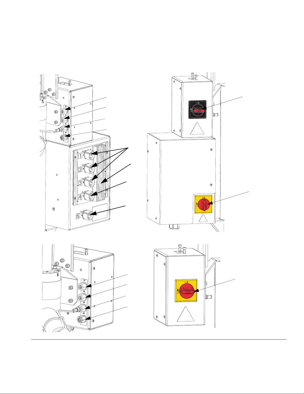
Heat Connections (Hoses and Accessories)
1. Connect heated hoses (with circular electrical
connectors) to Heat Control Box Ports 1, Port 2 or
Port 3 (C5).
2. Connect heated accessories to the square electrical
connector end of each heated hose that is used.
Single System Example
Example 1: Single system with two heated
hoses and one heated dispense valve.
• Hose 1 - Circular electrical connection to Port 1
(C5).
• Hose 2 - Circular electrical connectors to Port 2
(C5). *
• Heated valve - Square electrical connections from
hose 2 to iQ dispense valve (B). See F
IG
. 32.
F
IG
. 32
Note: port 4 is always used for heated pump. Port 5 is
always used for heated platen.
* Requires Heat Extension Cables. See page 82.
333586F 33
Page 34

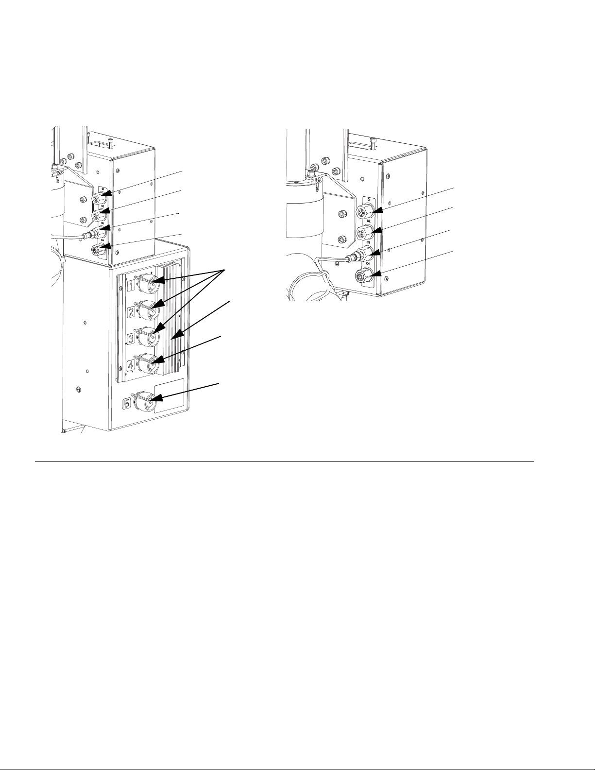
Setup
Tandem system includes:
• Four heated hoses
• One heated tandem block
• One heated valve
C5 - Port 1
C5 - Port 1
C5 - Port 2
C5 - Port 3
Ram 1
Ram 2
Ram 1
Ram 2
Hose 1
Circular electrical
connection
Hose 2
Square electrical
connection
Hose 3 *
Hose 4 *
Circular electrical
connection
Example 2: Tandem system with 4 heated
hoses, one heated tandem block and one
heated dispense valve.
• Hose 1 - To tandem block from pump 1 - circular
electrical connection to Port 1 (C5) of ram 1.
• Hose 2 - To tandem block from pump 2 - circular
electrical connector to Port 1 (C5) of ram 2. **
• Hose 3 - From tandem block - circular electrical
connector to part 2 (C5) of ram 1 or ram 2. *
• Hose 4 - From hose 3 to extend length of hose circular electrical connector to Port 3 (C5) of ram 1
or ram 2. *
• Heated Valve - Square electrical connection from
hose 4 to iQ dispense valve (B).
• Heated Tandem Block - Square electrical
connection from hose 1 or hose 2 to heated tandem
block (R). See F
IG
. 33
.
F
IG
. 33
Note: port 4 is always used for heated pump. Port 5 is
always used for heated platen.
* Requires Heat Extension Cables. See page 82.
** Heat extension cable included in tandem block kit
(25R848).
34 333586F
Page 35

Wet Cup
AN
Before starting, fill the Wet Cup (AN) 1/3 full with Graco
Throat Seal Liquid (TSL) or a compatible solvent.
Torque the Wet Cup
The Wet Cup (AN) is torqued at the factory; however,
throat packing seals on Severe Duty pumps may relax
over time. Check Wet Cup torque frequently after initial
start-up and periodically after the first week of produc-
tion. Maintaining proper Wet Cup torque is important to
extending seal life.
Setup
FIG. 34: Wet Cup
NOTE: MaxLife pumps use a special u-cup throat seal
that is non-adjustable and does not require periodic
torquing.
1. Follow the Pressure Relief Procedure on page 39.
2. Torque the Wet Cup (AN) 95-115 ft-lbs (128-155
N•m) using the packing nut wrench (supplied)
whenever necessary. Do not overtighten the Wet
Cup.
333586F 35
Page 36

Hose Care Guidelines
Hose Care Guidelines
Fluids subjected to heat in confined spaces can
create a rapid rise in pressure due to the thermal
expansion. Over-pressurization can result in equip-
ment rupture and serious injury.
• Open a valve to relieve the fluid expansion during
heating.
• Replace hoses pro actively at regular intervals
based on your operating conditions.
NOTE: Pressure check the hose assemblies. Refer to
the E-Flo iQ Supply System Operation manual for
instructions on priming the system. Check carefully for
leaks at the hose connections. If there are leaks, follow
the Pressure Relief Procedure on page 39.
Do not use hose to pull the equipment.
Use hose support spring.
Do not clamp, squeeze, or zip tie hose.
Minimum bend radius:
Use 2 wrenches to tighten. Torque to specification:
Do not tape or cover hose.
Do not flex hose when cold.
Do not bend or crimp hose.
Do not twist hose.
Use proper length hose.
Flush Before Using Equipment
The equipment was tested with lightweight oil, which is
left in the fluid passages to protect parts. To avoid
contaminating the fluid with oil, flush the equipment with
a compatible solvent before using the equipment. See
the E-Flo iQ Supply System Operation manual for
information about flushing the equipment. See Related
Manuals on page 3.
36 333586F
Page 37

Check Resistance (Heated Systems)
Check Resistance (Heated Systems)
Check Sensor Resistance
To reduce risk of injury or damage to equipment,
conduct these electrical checks with the Power
Junction Box Switch (AK) and the Disconnect Switch
(AZ) OFF.
NOTE: Instructions for checking sensor resistance
applies to heated systems only.
The package includes up to nine heat sensors and
controllers for each of the heated zones. To check
sensor resistance:
1. Turn the Power Junction Box Switch (AK) and the
Disconnect Switch (AZ) OFF.
2. Wait for components to cool down to ambient room
temperature 63°-77°F (17°-25°C). Check electrical
resistance for the components.
NOTE: Check resistance at ambient room temperature
63°-77°F (17°-25°C).
Check Heater Resistance
To reduce risk of injury or damage to equipment,
conduct these electrical checks with the Power
Junction Box Switch (AK) and the Disconnect Switch
(AZ) OFF.
NOTE: Instructions for checking heater resistance
applies to heated systems only.
1. Turn the Power Junction Box Switch (AK) and the
Disconnect Switch (AZ) OFF.
2. Make electrical resistance checks for the compo-
nents.
3. Replace any parts whose resistance readings do
not comply with the ranges listed in Table 1: Sen-
sors on page 38.
Circular Hose
AMZ Pins
First Heat Zone A, J
Second Heat Zone C, D
First RTD G, K
Second RTD M, K
Earth Ground B
3. Replace any parts whose resistance readings do
not comply with the ranges listed in Table 1: Sen-
sors on page 38.
Connector
333586F 37
Page 38

Check Resistance (Heated Systems)
Table 1: Sensors
Port Zone Component
1 Heated Hose 100 G, K See hose manual See hose manual
1
2
3
4
59
2 Heated Accessory 1 100 M, K See accessory manual
3 Heated Hose 100 G, K See hose manual See hose manual
4 Heated Accessory 2 100 M, K See accessory manual
5 Heated Hose 100 G, K See hose manual See hose manual
6 Heated Accessory 3 100 M, K See accessory manual
7 Not Used NA NA NA NA
8 Pump 1000 M, K 37 C, D
5 gallon platen 100 M, K 80 C, D
55 gallon platen 1000 M, K 15
RTD Range
(Ohms)
RTD Pin
Numbers
Heater Element
Resistance (Ohms)
Heater Pin
Numbers
See accessory
manual
See accessory
manual
See accessory
manual
C, D (#1)
A, J (#2)
38 333586F
Page 39

Pressure Relief Procedure
S
Pump
Pressures
Valve
Pressure
Pump
Pressure
Valve
Pressure
Single Unit Run Screen
Tandem Unit Run Screen
Pressure Relief Procedure
Follow the Pressure Relief Procedure whenever
you see this symbol.
This equipment stays pressurized until pressure is
manually relieved. To help prevent serious injury from
pressurized fluid, such as skin injection, splashing
fluid and moving parts, follow the Pressure Relief Pro-
cedure when you stop spraying and before cleaning,
checking, or servicing the equipment.
NOTE: The ADM must be in Local control mode to
depressurize the system. See the See the E-Flo iQ
Supply System Operation manual.
NOTE: For iQ Tandem Ram Supply Systems, make
sure both Ball Valves (S) on the Tandem Block are open
to ensure pressure is fully relieved.
soft key to open the iQ Dispense Valve (B) allowing
the system to depressurize.
FIG. 35: Tandem Block Ball Valves
NOTE: To relieve pressure for the entire E-Flo iQ
Dispense System, follow steps 1 through 12. To relieve
pressure for the fluid side only, leaving air on to the ram
cylinder follow steps 1 through 9.
1. Ensure the control mode is set to Local. See Con-
trol Modes in the E-Flo iQ Supply System Opera-
tion manual.
2. At the ADM (AF) Run screen, press the soft
key for Valve Depressurization. Then press the
333586F 39
3. The current pump pressure and current dispense
valve pressure show the progress of the
depressurization on the Run screen.
4. When all of the pressure has been relieved in the
system, press the soft key to close the iQ
Dispense Valve (B).
5. Press the soft key to exit the valve
depressurization mode.
NOTE: If using a tandem system, perform steps 6-12 on
both units.
6. If using an ambient system, turn the Disconnect
Switch (AZ) OFF. If using a heated system, turn the
Page 40

Pressure Relief Procedure
BA
BC
Open
Close
Power Junction Box Switch (AK) and the Disconnect
Switch (AZ) OFF.
7. Open the Pump Bleed Valve (AM). Have a container
ready to catch the drainage.
8. Leave the Pump Bleed Valve (AM) open until ready
to dispense again.
9. If you suspect the dispense valve is clogged or that
pressure has not been fully relieved:
a. VERY SLOWLY loosen the hose end coupling to
relieve pressure gradually.
b. Loosen the coupling completely.
c. Clear the obstruction in the tip/nozzle of the
valve.
10. Close the Main Air Slider Valve (BA).
FIG. 36: Air Control for Pressure Relief
11. Set the Ram Director Valve (BC) to DOWN. The
Ram (AA) will slowly drop.
12. Once the Ram (AA) is completely down, jog the Ram
Director Valve (BC) up and down to bleed air from
the Ram (AA) cylinders.
40 333586F
Page 41

Shutdown and Care of the Pump
Change Drums
Shutdown and Care of the Pump
NOTICE
To prevent damage to the pump from rust, never
leave water or water-based fluid in a carbon steel
pump overnight. If you are pumping a water-based
fluid, flush with water first. Then flush with a rust
inhibitor, such as mineral spirits. Relieve pressure,
but leave the rust inhibitor in the pump to protect
parts from corrosion.
1. Follow the Pressure Relief Procedure on page 39.
2. Set the Ram Director Valve (BC) to DOWN, and
lower the Ram (AA) to the desired position for
shutdown. If using a tandem system, perform this
step on both units.
3. Set the Ram Director Valve (BC) to neutral.
4. Stop the Pump at the bottom of the stroke to prevent
fluid from drying on the exposed displacement rod
and damaging the throat packings. See the E-Flo iQ
Supply System Operation manual for information
about jogging the Pump. See Related Manuals on
page 3.
5. Always flush the Pump before the fluid dries on the
displacement rod. See the E-Flo iQ Supply System
Operation manual for steps to flush the pump.
Keep hands away from the pump inlet to prevent
serious injury from moving parts.
If the Platen (AD) does not come out of the pail easily
when the Pump is being raised, the air assist tube (AT)
or check valve (416) may be plugged. A plugged valve
prevents air from reaching the underside of the plate to
assist in raising it from the pail. See F
1. Turn off power to the Electric Driver (AB):
a. If using an ambient Single Ram Supply System,
turn the red Disconnect Switch (AZ) OFF. See
F
IG
. 37.
b. If using a heated Single Ram Supply System,
turn the black Power Junction Box Switch (AK)
OFF. See F
c. If using an ambient Tandem Ram Supply
System, turn the red Power Junction Box Switch
(AK) OFF on the Ram Supply Unit that requires
a drum change only. See F
d. If using a heated Tandem Ram Supply System,
turn the black Disconnect Switch (AZ) OFF on
the Ram Supply Unit that requires a drum
change only. See F
IG
. 37.
IG
. 37.
IG
. 40 on page 44.
IG
. 37.
333586F 41
Page 42

Shutdown and Care of the Pump
AK
AZ
Heated System
AZ
Ambient System
BB
BC
BE
2. Set the Ram Air Regulator (BB) to 0 psi.
3. Set the Ram Director Valve (BC) to UP.
4. Slowly increase the pressure on the Ram Air
Regulator until the Platen (AD) starts to raise, and
immediately press and hold the Blowoff Button (BE)
until the Platen is completely out of the drum.
Excessive air pressure in the material drum could
cause the drum to rupture, causing serious injury. The
Platen must be free to move out of the drum. Never
use drum blowoff air with a damaged drum.
5. Release the Blowoff Button (BE) and allow the Ram
to rise to its full height.
F
IG
. 38. Integrated Air Controls
6. Remove the empty drum.
F
IG
. 37. Power Disconnect
42 333586F
Page 43

Maintenance
Fill Cap
Sight Glass
Bearing Pre-loads
Oil Drain Plug
AB
Maintenance
Driver Maintenance
NOTICE
Do not open/remove the gear cover. The gear side is
not intended to be serviced. Opening the gear cover
may alter the factory set bearing pre-load and may
reduce the product life.
Preventative Maintenance Schedule
The operating conditions of your particular system determine how often maintenance is required. Establish a pre-
ventative maintenance schedule by recording when and
what kind of maintenance is needed, and then determine
a regular schedule for checking your system.
Change the Oil
NOTE: Change the oil after a break-in period of 200,000
to 300,000 cycles. After the break-in period, change the
oil once per year.
Check Oil Level
See FIG. 39 below. Check the oil level in the sight glass on
a regular basis. The oil level should be near the halfway
point of the sight glass when the Driver (AB) is not run-
ning. If the oil is low, open the fill cap and add Graco Part
No. 16W645 ISO 220 silicone-free synthetic EP gear oil.
The oil capacity is approximately 1.0 - 1.2 quarts (0.9 - 1.1
liters). Do not overfill.
NOTICE
Only use oil with Graco part number 16W645. Any
other oil may not lubricate properly and can cause
damage to the drive train.
1. Follow the Pressure Relief Procedure on page 39.
2. Place a minimum 2 quart (1.9 liter) container under
the oil drain port.
3. Remove the oil drain plug. See F
of the drain plug. Allow all oil to drain from the Driver
(AB).
4. Reinstall the oil drain plug. Torque to 18-23 ft-lb
(25-30 N•m).
5. Open the fill cap and add Graco Part 16W645 ISO
220 silicone-free synthetic EP gear oil. Check the oil
level in the sight glass. Fill until the oil level is near the
halfway point of the sight glass. The oil capacity is
approximately 1.0 - 1.2 quarts (0.9 - 1.1 liters). Do not
overfill.
6. Reinstall the fill cap.
IG
. 39 for the location
FIG. 39: Sight Glass and Oil Fill Cap
Bearing Pre-Load
The bearing pre-loads are factory set and are not user
adjustable. Do not adjust the bearing pre-loads. See
APD20 Advanced Precision Driver Instructions-Parts
manual for maintenance information.
333586F 43
Page 44

Maintenance
EC
AT
EF
EG
TI10613A
EB
EB
55 Gallon Platen
5 Gallon Platen
Platen Maintenance
1. Follow the steps to Change Drums on page 41.
2. Follow the Pressure Relief Procedure on page 39.
3. Refer to parts illustration on page 75 and remove
the platen check valve (449) as shown.
4. Clear air assist tube (AT) in Platen (AD).
5. Clean all parts of the platen check valve (449) and
replace if necessary.
6. Remove Bleed Stick (EF) from Platen (AD). Push
Bleed Stick through Bleed Relieve Ports (EG) to
remove material residue.
Remove and Reinstall Wipers
Remove Platen Wipers
NOTE: Five gallon Platens have a single Wiper that
must be removed, and 55 gallon Platens have a top and
bottom Wiper that must be removed.
1. Follow the Pressure Relief Procedure on page 39.
2. If using an ambient system, turn the Disconnect
Switch (AZ) OFF. If using a heated system, turn the
Power Junction Box Switch (AK) and the
Disconnect Switch (AZ) OFF.
3. To replace worn or damaged Wipers (EB), raise
Platen up out of drum. Remove drum from base.
Wipe fluid off of Platen.
4. Cut the Wiper(s) (EB) with knife and remove from
Platen. See F
IG
. 41.
FIG. 40
FIG. 41
44 333586F
Page 45

Maintenance
TI10614A
EB
55 Gallon Platen
5 Gallon Platen
EB
Reinstall Platen Wipers
NOTE: Five gallon Platens have a single Wiper that
must be reinstalled, and 55 gallon Platens have a top
and bottom Wiper that must be reinstalled.
1. Using a wooden or plastic tool to prevent damage to
the Wiper (EB), clean all material from the seal
grooves.
2. Working from the bottom, angle one Wiper (EB)
over the back of the Platen (AD). See F
3. Insert the Wiper (EB) in the top groove and run the
front of the Wiper into the groove.
4. If using a 55 gallon Platen, insert the second Wiper
(EB) in the lower groove and run the front of the
Wiper into the groove.
5. Lubricate the outside of the Wiper with lubricant
compatible with the material being pumped. Check
with the material supplier.
IG
. 42.
Recycling and Disposal
End of Product Life
At the end of the product’s useful life, dismantle and
recycle it in a responsible manner.
• Perform the Pressure Relief Procedure.
• Drain and dispose of fluids according to applicable
regulations. Refer to the material manufacturer’s
Safety Data Sheet.
• Remove motors, batteries, circuit boards, LCDs
(liquid crystal displays), and other electronic
components. Recycle according to applicable
regulations.
• Do not dispose of batteries or electronic
components with household or commercial waste.
F
IG
. 42
• Deliver remaining product to a recycling facility.
333586F 45
Page 46

Troubleshooting
Troubleshooting
2. Check all possible problems and causes before
disassembling the Ram, Pump, or Platen.
NOTE: Refer to Supply Unit Operation manual for
descriptions of ADM diagnostic codes.
NOTE: Refer to your Pump package manual for Pump
1. Follow Pressure Relief Procedure, page 39,
before checking or repairing the Ram, Pump, or
Platen.
Supply Systems Troubleshooting
Problem Cause Solution
System will not turn ON. No power to unit. Check main power breaker is turned
Ram will not raise or lower. Closed air valve or clogged air line. Open, clear.
Not enough air pressure. Increase.
Worn or damaged piston. Replace. See Ram Supply Unit
Hand valve closed or clogged. Open, clear.
Ram raises and lowers too fast. Air pressure is too high. Decrease.
Air leaks around cylinder rod. Worn rod seal. Replace. See Ram Supply Unit
Fluid squeezes past ram plate wip-
ers.
Pump will not prime properly or
pumps air.
Air assist valve will not hold drum
down or push plate up.
Air pressure too high. Decrease.
Worn or damaged wipers. Replace. See Remove and Rein-
Not enough pressure. Increase pressure setting.
Worn or damaged piston. Replace. See Pump manual.
Hand valve closed or clogged. Open, clear. See Platen Mainte-
Hand valve is dirty, worn, or dam-
aged.
Closed air valve or clogged air line. Open, clear. See Platen Mainte-
Not enough air pressure. Increase.
Valve passage clogged. Clean. See Platen Maintenance on
troubleshooting.
ON.
Check power cord is connected.
Repair on page 55.
Repair on page 55.
stall Wipers on page 44.
nance on page 44.
Clean, service.
nance on page 44.
page 44.
46 333586F
Page 47

Troubleshooting
Heat Control Box Troubleshooting
Problem Cause Solution
System does not heat. Blown fuse. Replace fuse.
Over-temperature switch tripped. Measure over-temperature switch
resistance. It should read close to 0
ohms when at room temperature. If
open, replace over-temperature
switch.
Cable to over-temperature switch is
off or broken.
Electrical short. Check jumpers.
Disconnect switched OFF. Check disconnects.
Slow warm-up time. Low incoming voltage. Verify incoming voltage is 200V L-N
Insufficient power supplied to sys-
tem.
Zone Types set up incorrectly. Ensure Zone Types are set up cor-
Open heater. Verify resistance of heaters. See
Check connection of cable to
over-temperature switch both to main
board and to switch. If connection is
good, look for a break in the wire.
Check resistances on heater rods
and RTDs.
Check cable connections.
or 240V L-C.
Connect system to a power supply
capable of maximum power per sys-
tem specification. All changes must
be performed by a qualified electri-
cian.
rectly in the ADM.
Check Heater Resistance on page
37.
Platen Valve Kit Troubleshooting
Problem Cause Solution
Material leak. Loose fitting connection. Ensure fittings are tight. See Parts
on page 61 for part identification.
Improper fitting used. Replace fitting. See Parts on page
61 for part identification.
System does not depressurize as
expected.
Valve does not open or close as
expected.
333586F 47
Clogged hose or fittings. Flush or replace clogged pieces.
Failed solenoid actuation. Replace solenoid.
Solenoid mufflers plugged. Replace solenoid mufflers.
No air to solenoid. Re-establish air supply to solenoid.
Page 48

Repair
TI10422A
426
425
427
428
Heated Platen
Ambient Platen
428
426
427
Repair
Disconnect Pump from Platen
The Pump is mounted to the Platens by different mount-
ing kits. See the Repair Kits on page 81.
55 Gallon Platen
1. Follow the Pressure Relief Procedure on page 39.
2. Turn off power to the ram:
a. If using an ambient Single Ram Supply System,
turn the red Disconnect Switch (AZ) OFF.
b. If using a heated Single Ram Supply System,
turn the red Disconnect Switch (AZ) OFF.
c. If using an ambient Tandem Ram Supply
System, turn the red Disconnect Switch (AZ)
3. Remove four hex screws (426), four clamps (427),
4. Carefully pull Pump away to prevent damage to
OFF on the Ram Supply Unit that requires repair
only.
d. If using a heated Tandem Ram Supply System,
turn the red Disconnect Switch (AZ) OFF on the
Ram Supply Unit that requires repair only.
and washers (425).
Pump inlet and remove o-ring (428).
FIG. 43: 55 Gallon Mounting Kit
48 333586F
Page 49

20, 30, and 60 Liter Platen
463
462
463
462
Ambient Platen
Heated Platen
1. Follow the Pressure Relief Procedure on page 39.
2. Turn off power to the ram:
a. If using an ambient Single Ram Supply System,
turn the red Disconnect Switch (AZ) OFF.
b. If using a heated Single Ram Supply System, turn
the red Disconnect Switch (AZ) OFF.
c. If using an ambient Tandem Ram Supply System,
turn the red Disconnect Switch (AZ) OFF on the
Ram Supply Unit that requires repair only.
d. If using a heated Tandem Ram Supply System,
turn the red Disconnect Switch (AZ) OFF on the
Ram Supply Unit that requires repair only.
3. Loosen two 5/16 in. screws (462) from Platen (AD).
Repair
4. Carefully pull Pump away to prevent damage to Pump
inlet. If using a Pump with an intake adapter, remove
screws (472), adapter (471), and o-rings (463) from
Pump inlet.
F
IG
. 44: 20 liter mounting kit
333586F 49
Page 50

Repair
Connect Platen
55 Gallon Platen
1. Place o-ring (428) from mounting kit on the Platen
(AD). If attached to plate, place Displacement Pump
(AC) onto Platen (AD). See F
2. Secure Pump’s intake flange to plate with screws
(426), washers (425), and clamps (427) included in
mounting kit 255392.
20 Liter Platen
NOTE: Before installing the 20, 30, or 60 liter Platen to a
Pump with an intake adapter, install adapter and o-ring
from mounting kit using the two set screws. See F
1. Place o-ring (463) from mounting kit on Pump
intake. Loosen the Pump intake flange screws (462)
and carefully lower Pump onto o-ring (463) and
Platen.
2. Secure Pump’s intake flange to plate with screws
(462).
IG
. 43.
IG
. 44.
Remove Displacement Pump
The procedure for removing the Displacement Pump
(AC) depends on which Driver (AB) and Platen (AD) the
unit uses. Find your Ram Assembly (AA), Driver (AB),
and Platen (AD) below to remove the Displacement
Pump (AC). Refer to your Displacement Pump manual
to repair the Displacement Pump.
If the Driver does not require servicing, leave it attached
to its mounting. If the Driver does need to be removed,
see Remove Driver on page 52.
D200 3 in. and D200s 6.5 in. Ram Supply
Units
1. Follow the Pressure Relief Procedure on page 39.
2. Turn off power to the ram:
a. If using an ambient Single Ram Supply System,
turn the red Disconnect Switch (AZ) OFF.
Remove Wipers
See Remove and Reinstall Wipers on page 44.
Install Wipers
See Remove and Reinstall Wipers on page 44.
b. If using a heated Single Ram Supply System,
turn the red Disconnect Switch (AZ) OFF.
c. If using an ambient Tandem Ram Supply
System, turn the red Disconnect Switch (AZ)
OFF on the Ram Supply Unit that requires
repair only.
d. If using a heated Tandem Ram Supply System,
turn the red Disconnect Switch (AZ) OFF on the
Ram Supply Unit that requires repair only.
3. See Disconnect Displacement Pump in your
Pump package manual.
4. Open the Main Air Slider Valve (BA).
50 333586F
Page 51

Repair
106
105
107
105a
5. Raise the Driver (AB):
a. Loosen nut (105a) under Ram bar and thread it
down the threaded rod (106) to the lift ring
adapter (107) holding the Driver (AB). Use
wrench on nut (105) on top of Ram bar to raise
Driver (AB).
7. Use two people to lift out the Displacement Pump
(AC).
F
IG
. 45
b. For Driver (AB) with smaller Platens (AD) and
all ram supply units: See procedure for D60 3
in. Dual Post Ram Supply Units on page 51.
6. See Disconnect Pump from Platen on page 48 to
disconnect the Platen (AD) from the Displacement
Pump (AC).
FIG. 46
D60 3 in. Dual Post Ram Supply Units
1. Follow the Pressure Relief Procedure on page 39.
2. Turn off power to the ram:
a. If using an ambient Single Ram Supply System,
turn the red Disconnect Switch (AZ) OFF.
b. If using a heated Single Ram Supply System,
turn the red Disconnect Switch (AZ) OFF.
c. If using an ambient Tandem Ram Supply
System, turn the red Disconnect Switch (AZ)
OFF on the Ram Supply Unit that requires
repair only.
d. If using a heated Tandem Ram Supply System,
turn the red Disconnect Switch (AZ) OFF on the
Ram Supply Unit that requires repair only.
3. See Disconnect Displacement Pump in your
Pump packages manual.
333586F 51
Page 52

Repair
4. See Disconnect Pump from Platen on page 48 to
disconnect the Platen (AD) from the Displacement
Pump (AC).
5. Open the Main Air Slider Valve (BA).
6. Raise the Ram Assembly (AA) to lift the Driver (AB)
away from the Displacement Pump (AC).
7. Remove Displacement Pump (AC) and service as
needed.
Install Displacement Pump
D200 3 in. and D200s 6.5 in. Ram Supply
Units
1. Insert Displacement Pump (AC) on Platen (AD).
Follow Connect Platen steps on page 50.
2. See Reconnect Displacement Pump in your
Pump package manual.
3. Connect Driver (AB):
Remove Driver
To avoid serious injury when installing and removing
the Driver, make sure the Driver is supported at all
times.
1. Follow the Pressure Relief Procedure on page 39.
2. Turn off power to the Ram:
a. If using an ambient Single Ram Supply System,
turn the red Disconnect Switch (AZ) OFF.
b. If using a heated Single Ram Supply System,
turn the red Disconnect Switch (AZ) OFF.
c. If using an ambient Tandem Ram Supply
System, turn the red Disconnect Switch (AZ)
OFF only on the Ram Supply Unit the Driver is
being removed from.
a. Use wrench on nut (105) on top of Ram bar to
lower Driver (AB) onto Displacement Pump
(AC). See F
up and tighten it under Ram bar. Tighten nut
(105) below the crossbar to 25 ft-lb (34 N•m)
maximum.
IG
. 45 on page 51. Thread nut (105)
D60 3 in. Dual Post Ram Supply Units
1. Raise Ram (AA) to install Displacement Pump (AC)
to Platen (AD).
2. Insert Displacement Pump (AC) on Platen (AD).
Follow Connect Platen steps on page 50.
3. See Reconnect Displacement Pump in your
Pump packages manual.
d. If using a heated Tandem Ram Supply System,
turn the red Disconnect Switch (AZ) OFF only
on the Ram Supply Unit the Driver is being
removed from.
3. See Disconnect Displacement Pump in your
Pump package manual.
4. Disconnect power from the Driver (AB):
a. Remove the Driver housing cover (HC).
52 333586F
Page 53

Repair
HC
CG
AB
126
125
127
125
Lift Ring
256
255
259
b. Disconnect the wires inside the Driver housing.
IG
See F
IG
. 47: Wires in Driver Housing
F
. 47.
c. Loosen the cord grip (CG).
d. Remove wires from Driver housing by pulling
them through the cord grip (CG).
e. Disconnect the cables connected to ports 1-6
on the side of the Driver (AB), shown in F
IG
. 49.
5. Disconnect Driver (AB):
a. D200 3 in. and D200s 6.5 in. ram supply units:
Attach a secure hoist to the driver lift ring.
Loosen nut (125) below crossbar. Use wrench
to hold lift ring adapter (127) in place and loosen
threaded rod (126) above crossbar with another
IG
wrench. See F
. 50.
FIG. 50: 55 Gallon Platen
b. D60 3 in. ram supply units: Remove screws
(255) and washers (256) from mounting plate
(259). Using a secure hoist, lift the Driver (AB)
from the mounting plate (259). See F
IG
. 51.
F
IG
. 48
F
IG
. 51: D60 with Ram
F
IG
. 49
333586F 53
Page 54

Repair
126
125
127
125
124
Install Driver
To avoid serious injury when installing and removing
the Driver, make sure the Driver is supported at all
times.
D200 3 in. and D200s 6.5 in. Ram Supply
Units
55 gallon platen:
1. Using a capable hoist, insert tie rods into the Dis-
placement Pump (AC) and secure the Driver (AB) to
the Pump (AC).
a. See Reconnect Displacement Pump in your
Pump package manual.
b. Install threaded rod (126) through center hole in
the crossbar. Install lock washers (124) and
nuts (125) onto threaded rod (126), both above
and below crossbar. Use wrench to hold lift ring
adapter (127) and tighten threaded rod (106)
into lift ring adapter (127) using another wrench.
See F
IG
. 52.
2. Connect power to the Driver (AB). Follow a-e of step
4 on page 52 in reverse.
3. If using an ambient system, turn the Disconnect
Switch (AZ) ON. If using a heated system, turn the
Power Junction Box Switch (AK) and the
Disconnect Switch (AZ) ON.
D60 3 in. Dual Post Supply Unit
1. Using a secure hoist, attach Driver (AB) to mounting
plate (259) with screws (255) and washers (256).
See F
IG
. 51 on page 53.
2. See Reconnect Displacement Pump in your
Pump package manual.
3. Connect power to the Driver (AB). Follow a-e of step
4 on page 52 in reverse.
c. Tighten nut (125) below crossbar to 25 ft-lb (34
N•m) maximum.
d. Tighten nut (125) above crossbar to lock Driver
(AB) in place.
F
IG
. 52
54 333586F
Page 55

Repair
TI10784A
134
136
137
135
142
132
133
Ram Supply Unit Repair
To reduce the risk of serious injury whenever you are
instructed to relieve pressure always follow the
Pressure Relief Procedure on page 39. Do not use
pressurized air to remove the guide sleeve or the
piston.
D200s 6.5 in. Ram Piston Rods
Always service both cylinders at the same time. When
you service the Lift Rod (AL) always install new o-rings
in the piston rod seal and Ram piston.
Disassemble Piston Rod Seal
1. Follow the Pressure Relief Procedure on page 39.
2. Turn off power to the ram:
a. If using an ambient Single Ram Supply System,
turn the red Disconnect Switch (AZ) OFF.
8. Remove guide sleeve (135) by sliding it off of rod
(132). Four 1/4 in -20 holes are provided to ease
removal of the guide sleeve.
9. Inspect parts for wear or damage.
FIG. 53: 6.5 in. Piston Rod Seal
b. If using a heated Single Ram Supply System,
turn the red Disconnect Switch (AZ) OFF.
c. If using an ambient Tandem Ram Supply
System, turn the red Disconnect Switch (AZ)
OFF on the Ram Supply Unit that requires
repair only.
d. If using a heated Tandem Ram Supply System,
turn the red Disconnect Switch (AZ) OFF on the
Ram Supply Unit that requires repair only.
3. Remove the nuts (123) and lockwashers (122) hold-
ing the tie bar (219) to the piston rods (132). See
parts illustration on page 61.
4. Remove nuts (303, 305) and washers (302, 304).
See parts illustration on page 67.
5. Lift tie bar (219) off of rods.
6. Remove retaining ring (136) by gripping the ring tab
with a pair of pliers and rotating the ring out of its
groove.
7. Remove snap ring (134) and rod wiper (133).
Assemble Piston Rod Seal
1. Install new o-rings (137,142), rod wiper (133), and
snap ring (134). Lubricate packings with o-ring lubri-
cant.
2. Slide guide sleeve (135) onto rod (132) and push it
into cylinder. Replace retaining ring (136) by feeding
it around the guide sleeve groove.
3. Reinstall tie bar (219) using nuts (123) and lock-
washers (122). Torque to 40 ft-lb (54 N•m).
4. Reinstall washers (302, 304) and nuts (303, 305).
Disassemble Ram Piston
1. Follow the Pressure Relief Procedure on page 39.
2. Turn off power to the ram:
a. If using an ambient Single Ram Supply System,
turn the red Disconnect Switch (AZ) OFF.
b. If using a heated Single Ram Supply System,
turn the red Disconnect Switch (AZ) OFF.
c. If using an ambient Tandem Ram Supply
System, turn the red Disconnect Switch (AZ)
333586F 55
Page 56

Repair
TI10785A
132
138
139
137
141
140
OFF on the Ram Supply Unit that requires
repair only.
d. If using a heated Tandem Ram Supply System,
turn the red Disconnect Switch (AZ) OFF on the
Ram Supply Unit that requires repair only.
3. Remove nuts (123) and lockwashers (122) holding
the tie bar (219) to the piston rods (132). See page
61.
4. Remove nuts (303, 305) and washers (302, 304).
See parts illustration on page 67.
5. Lift tie bar (219) off rods.
6. Remove retaining ring (136) by gripping the ring tab
with a pair of pliers and rotating the ring out of its
groove.
7. Remove guide sleeve (135) and slide it off piston
rod (132).
NOTICE
Do not tilt the piston rod to one side when removing it
from the base or when installing it. Such movement
can damage the piston or inside surface of the base
cylinder.
8. Carefully lay piston (141) and rod (132) down so rod
will not be bent. Remove bottom retaining ring (138)
and o-ring (139). Remove piston guide band (140).
Slide piston (141) off piston rod (132).
Assemble Ram Piston
1. Install new o-rings (139, 137) on piston rod (132)
and piston (141). Lubricate the piston (141) and
o-rings (139, 137). Reinstall piston (141) and lower
retaining ring (138) onto piston rod (132). Install pis-
ton guide band (140) onto piston (141).
2. Carefully insert piston (141) into cylinder and push
rod (132) straight down into cylinder. Add three
ounces of lubricant to each cylinder after inserting
the piston (141).
3. Slide guide sleeve (135) onto piston rod (132).
4. Install retaining ring (134) and tie bar (219). Perform
steps to Disassemble Ram Piston in reverse
order.
D200 and D60 3 in. Ram Piston Rods
Always service both cylinders at the same time. When
you service the piston rod always install new o-rings in
the piston rod seal and Ram piston.
Disassemble Piston Rod Seal and Bearing
1. Follow the Pressure Relief Procedure on page 39.
2. Access piston rod seal and bearing.
a. For D200 3 in. Ram: Remove nuts (125) and
lockwashers (124) holding the tie bar (219) to
the piston rods (246). Remove nuts (305) and
washers (304). Remove tie bar (219). Refer to
parts illustration on page 63.
b. For D60 3 in. Ram: Ensure Ram is in lowest
position. Remove nuts (125) and lockwashers
(254) from piston rods (261). Remove entire
pump package, including the mounting plate
(259) off of the piston rods (261). Secure Pump
package so Pump (AC) and Platen (AD) will not
fall. See page 68.
3. Remove retaining ring (218).
4. Remove piston rod seal and bearing.
a. Slide end cap (241), pin (238), o-ring (245), and
spring (244) up off of the piston rod (261, 246).
F
IG
. 54: 6.5 in. Ram Piston
Remove retaining ring (242) and bearing (243)
from end cap (241) and remove o-ring (240).
56 333586F
Page 57

Repair
WLD
261,
244
242
243
241
245
218
238
240
D200 and D60 3 in. Rams
246
TI10521A
261, 246
245
247
239
124
125
5. Inspect parts for wear or damage. Replace as nec-
essary.
NOTE: Do not reinstall end cap assembly if the ram
piston (247) needs to be removed from the piston rod.
See the next page for ram piston repair instructions.
Disassemble Ram Piston
1. Complete steps 1-4 from Disassemble Piston Rod
Seal and Bearing to remove the end cap from the
piston rod.
NOTICE
Do not tilt the piston rod to one side when removing it
from the base or when installing it. Such movement
can damage the piston or inside surface of the base
cylinder.
2. Carefully lay piston (247) and rod (261, 246) down
so piston rod will not be bent. Remove nut (125),
washer (124), piston (247), outer o-ring (245), and
inner o-ring (239).
3. Inspect parts for wear or damage. Replace as nec-
essary.
F
IG
. 55: 3 in. Piston Rod Seal
Assemble Piston Rod Seal and Bearing
See F
IG
. 55 on page 57.
1. Lubricate o-ring (240) and bottom bearing (243).
a. Install o-ring (240), bottom bearing (243), and
retaining ring (242) into end cap (241).
b. Install new o-ring (245) and pin (238) on end
cap (241). Lubricate o-ring (245) and end cap
(241).
c. Slide spring (244) and end cap (241) on piston
rod (261, 246).
2. Install retaining ring (218).
3. For D200 3 in Ram: Install tie bar (219), washers
(124), and nuts (125).
4. For D60 3 in. Ram: Remount mounting plate (259)
and attach nuts (255) and lockwashers (256).
Torque to 40 ft-lb (54 N•m).
333586F 57
IG
. 56: 3 in. Ram Piston
F
Assemble Ram Piston
1. Install new o-rings (245, 239) and lubricate piston
(247) and o-rings.
2. Apply medium strength thread sealant. Install piston
(247), washer (124), and nut (125) on piston rod
(261, 246).
3. Carefully insert piston (247) into cylinder and push
piston rod (261, 246) straight down into cylinder.
4. Slide spring (244) and end cap (241) onto piston rod
(261, 246).
5. For D200 3 in. Rams: Install retaining ring (218), tie
bar (219), washers (124), and nuts (125).
6. For D60 3 in. Rams: Install retaining ring (218) and
install mounting plate (259) with nuts (255) and
washers (256) with Pump package and Platen.
Page 58

Repair
350
333
AX
AMZ
Replace Heat Control Box Electrical Component(s)
1. Turn the Heat Control Box Disconnect Switch (AZ)
OFF.
2. Remove the door (350) on the Heat Control Box
DANGER
SEVERE ELECTRIC SHOCK HAZARD
This equipment can be powered by more than 240 V.
Contact with this voltage will cause death or serious
injury.
• Turn the Power Junction Box Switch (AK) and the
Disconnect Switch (AZ) OFF before disconnecting
any cables and before servicing equipment.
(AX).
3. Use a non-conductive fuse puller tool to remove the
blown fuse.
Using an improper tool, such as a screwdriver or pli-
ers may break the fuse or cause damage to board.
NOTICE
Replace Auto Multi-Zone (AMZ) Fuse(s)
NOTE: Fuses FHA and FHB are not replaceable. If FHA
or FHB fuses are blown, order AMZ Replacement Kit,
25R533.
4. Install a new fuse into the empty fuse holder.
5. Install the Heat Control Box door (350).
Replace Auto Multi-Zone (AMZ)
1. Turn the Heat Control Box Disconnect Switch (AZ)
OFF.
2. Loosen screws and remove the door (350) on the
Heat Control Box (AX).
F
IG
. 57
NOTICE
To prevent system damage, always use fast acting
fuses. Fast acting fuses are required for short-circuit
protection.
Fuse Part Identification
F1A-F4B 129346 250VAC, 12.5A, fast acting
FHA-FHB - - - - - 250VAC, 25A
58 333586F
IG
. 58
F
3. Remove the AMZ:
a. Disconnect the heated electrical connections
from the back of the AMZ.
Page 59

Repair
b. Disconnect the cables from the AMZ on the
inside of the Heat Control Box (AX).
c. Remove the four screws (333) used to mount
the AMZ to the back of the Heat Control Box
(AX) and remove the AMZ.
4. Insert the new AMZ:
a. Set the AMZ dial position number 1 on the dial
for single ram systems.
b. Set AMZ dial to position number 2 for ram 2 for
a tandem system. NOTE: Ram 2 does not
include an ADM. .
Replace Advanced Display Module (ADM)
NOTICE
The ADM stores useful lifetime and diagnostic data
that will be lost when it is replaced. To keep this data,
perform a USB download prior to replacing the ADM.
1. Turn the Heat Control Box Disconnect Switch (AZ)
OFF.
2. Disconnect the cable from the bottom of the ADM
(AF).
3. Remove the ADM (AF) from the bracket (114). See
Parts on page 61.
4. Install the new ADM (AF) into the bracket (114).
5. Connect the cable to the bottom of the new ADM
(AF).
Replace Power Supply
NOTE: Instructions for replacing the power supply
applies to heated systems only.
F
IG
. 59: AMZ Dial Position
c. Mount the AMZ to the back of the Heat Control
Box (AX) using the four screws (333) removed
from the original AMZ.
d. Reconnect the cables on the inside of the Heat
Control Box (AX) to the AMZ.
e. Reconnect the heated electrical connections to
the back of the AMZ.
5. Replace the Heat Control Box door (350).
1. Turn the Heat Control Box Disconnect Switch (AZ)
OFF.
2. Loosen the screws and remove the door (350) on
the Heat Control Box (AX).
3. Disconnect the power supply harness from the AMZ
(headers J3 and J21).
4. Remove the power supply (338) from the din rail in
the Heat Control Box (AX).
5. Disconnect the power supply harness from the
power supply.
6. Mount the new power supply to the din rail in the
Heat Control Box (AX).
7. Connect the power supply harness to the AMZ
(headers J3 and J21).
8. Close the Heat Control Box door (350).
333586F 59
Page 60

Repair
Open Here
Replace Fuses in Harness (25R652)
The harness comes with fuses installed. Follow these steps to replace a fuse.
1. Turn the Heat Control Box Disconnect Switch (AZ) OFF.
2. Remove the Heat Control Box door (350).
3. Unscrew the spring-loaded fuse holder to open it. The fuse can be easily removed by hand.
F
IG
. 60
4. Install the new fuse.
5. Reconnect and tighten the fuse holder.
6. Install the Heat Control Box Door (350).
NOTICE
To prevent damage to the AMZ circuit board, use
only 5 x 20 mm, 10 Amp AC, fast acting fuses. Fast
acting fuses are required for short-circuit protection.
60 333586F
Page 61

Parts
Model EZC2661 Shown
Detail A
114
102,
109
103,
113
112
106
106
107,108
108
107
108
104
101
110
131
115
124
105
126
125
123
122
134
133
134
142
137
135
136
132
116
130
111
138
139
138
141
140
137
131
117
119
118
106
131
121
219
143
144
Detail B
107,108
265
264
262
263
107,108
145
146
NOTE: If using a tandem system,
the ADM is only included with the
iQ Ram Supply Unit 1 (A).
107
267
D200s 6.5 in. Ram Supply Units
Parts
333586F 61
Page 62

Parts
D200s 6.5 in. Ram Supply Units, EZC2661
Ref. Part Description Qty.
101 102040 NUT 1
102 110755 WASHER, plain 1
103 117017 WASHER 1
104 15V954 LABEL, valve, shutoff, air con-
trol
105 --- LABEL, cross bar 1
106 C12509 TUBE, nylon 15
107 100016 WASHER, lock 15
108 121112 SCREW 15
109 --- SCREW 1
110 --- BRACKET, mounting, painted 1
111 --- RAM, 6.5 in. 1
112 --- BRACKET, pendant pivot,
painted
113 --- FASTENER, knob 2
114 --- BRACKET, mounting, assembly 1
115 24C824 KIT, air control 1
116 --- JUNCTION BOX, ram mounted,
E-drive
117 C19853 SCREW 2
118 C32467 STOP, drum 2
119 C38185 WASHER, lock 2
120✖ --- SEALANT, pipe, sst 1
121 15M531 ROD, follower 2
122 101015 WASHER, lock 2
123 C19187 NUT 2
124 101533 WASHER, spring lock 2
125 101535 NUT 2
126 15J992 ROD, threaded 1
127✖ 15J991 ADAPTER, lift ring 1
128✖ 15J993 RING, lift, plate 1
129✖ --- LUBRICANT, anti-seize 1
130▲ 196548 LABEL, caution 1
131▲ 15J074 LABEL, safety, crush & pinch 3
132 C32401 ROD 2
133* C03043 RING, snap 2
134* C31001 WIPER, rod 2
135 18C233 SLEEVE, guide 2
136* C32409 RING, retaining 2
137* C38132 PACKING, o-ring 4
138* C20417 RING, retaining 4
139* 158776 PACKING, o-ring 2
140* C32408 BAND, guide 2
141 C32405 PISTON, elevator air 2
142* C02073 PACKING, quad ring 2
143 --- RAM, D60, electric driver, heat 1
144▲ 15G303 LABEL, warning, electrical 1
145 --- CONTROL, box, heat 1
146▲ 17J476 LABEL, safety, warning 1
219 167646 BEAM, tie 1
Ref. Part Description Qty.
262 130787 SENSOR, barrel 1
263 123673 HARNESS 1
264 255381 ACTUATOR, sensor,
1
265 --- BRACKET, lvl sensor, dual,
267 234966 KIT, accessory, hose hanger 1
▲ Replacement safety labels, tags, and cards are
available at no cost.
* Parts included in Ram Supply Units Repair Kit
1
1
918432 (purchase separately).
✖ Not shown.
low/empty, painted
D200
1
1
62 333586F
Page 63

D200 3 in. Ram Supply Units
Model EZC2561 Shown
Detail A
106
106
107,108
221
107,108
103,113
102,
109
114
112
107
108
107
108
131
101
115
104
125
124
239
247
245
220
201,
213,
107
116
130
224
225
107,
108
205,
217
226
246
244
241
238
242
243
240
245
218
125
124
219
105
126
125
208
252
106
223
117
119
118
143
144
107,108
Detail B
107,108
265
264
262
263
145
146
NOTE: If using a tandem system,
the ADM is only included with the
iQ Ram Supply Unit 1 (A).
267
Parts
333586F 63
Page 64

Parts
D200 3 in. Ram Supply Units, EZC2561
Ref. Part Description Qty.
101 102040 NUT 1
102 110755 WASHER, plain 1
103 117017 WASHER 1
104 15V954 LABEL, valve, shutoff, air control 1
105 --- LABEL, cross bar 1
106 C12509 TUBE, nylon 15
107 100016 WASHER, lock 16
108 121112 SCREW 12
109 --- SCREW 1
112 --- BRACKET, pendant pivot, painted 1
113 --- FASTENER, knob 1
114 --- BRACKET, mounting, assembly 1
115 24C824 KIT, air control 1
116 --- JUNCTION BOX, ram mounted,
e-drive
117 C19853 SCREW 2
118 C32467 STOP, drum 2
119 C38185 WASHER, lock 2
120✖ --- SEALANT, pipe, sst 1
124* 101533 WASHER, spring lock 6
125* 101535 NUT, full hex 6
126 15J992 ROD, threaded 1
127✖ 15J991 ADAPTER, lift ring 1
128✖ 15J993 RING, lift, plate 1
129✖ --- LUBRICANT, anti-seize 1
130▲ 196548 LABEL, caution 1
131▲ 15J074 LABEL, safety, crush & pinch 4
143 --- RAM, D60, electric driver, heat
144▲ 15G303 LABEL, warning, electrical 1
145 --- CONTROL, box, heat 1
146▲ 17J476 LABEL, safety, warning 1
201 100014 SCREW 4
205 108050 WASHER, lock, spring 6
208 189559 CAP, end 2
213 100015 NUT 4
217 121518 SCREW 6
218* 127510 RING, retaining, internal 2
219 167646 BEAM, tie 1
220 --- RAM, weldment, 3” 1
221 255296 BRACKET, mounted, painted 1
223 128863 FITTING, elbow 2
224 --- BRACKET, mounting, btm 1
225 --- BRACKET, mounting, acc. box 1
226 --- BRACKET, mounting, ram 1
234✖ --- LUBRICANT, grease 1
235✖ --- LUBRICANT, oil 1
237✖ --- SEALANT, thread, med strength 1
238* --- BEARING, ram end cap 1
239* 156401 PACKING, o-ring 1
240* 156698 PACKING, o-ring 1
241* 15F453 RETAINER, retaining ring 1
242 15M295 BEARING, ram end cap 1
243 15U979 PIN, spring, straight 1
244* 160138 SPRING, compression 1
245* 160258 PACKING, o-ring 2
246 167651 ROD, piston ram 1
Ref. Part Description Qty.
247 183943 PISTON 1
251✖ C20987 PACKING, o-ring 1
252 167652 ROD, tie ram 2
262 130787 SENSOR, barrel 1
263 123673 HARNESS 1
264 255381 ACTUATOR, sensor, low/empty,
painted
265 --- BRACKET, lvl sensor, dual, D200,
pnt
267 234966 KIT, accessory, hose hanger 1
▲ Replacement safety labels, tags, and cards are
available at no cost.
1
* Parts included in Ram Supply Units Repair Kit
255687 (purchase separately).
✖ Not shown.
1
1
64 333586F
Page 65

D60 3 in. Ram Supply Units
Model EZC2424 Shown
Detail A
107
108
107
108
131
101
115
104
254
125
106
107,108
106
107,108
103,113
102,
109
223
112
254,125
106
223
258
257
117
119
118
259
261
244
218
245
240
243
242
238
241
125
124
239
247
245
266
Detail B
107,108
265
264
262
263
114
221
260
256
255
226
201,107
213
224
130
116
205,
217
225
107,108
143
144
145
146
NOTE: If using a tandem system,
the ADM is only included with the
iQ Ram Supply Unit 1 (A).
268
Parts
333586F 65
Page 66

Parts
D60 3 in. Ram Supply Units, EZC2424
Ref. Part Description Qty.
101 102040 NUT 1
102 110755 WASHER, plain 1
103 117017 WASHER 1
104 15V954 LABEL, valve, shutoff, air control 1
106 C12509 TUBE, nylon, rnd 2
107 100016 WASHER, lock 18
108 121112 SCREW 14
109 --- SCREW 1
112 --- BRACKET, pendant pivot, painted 1
113 --- FASTENER, knob 1
114 --- BRACKET, mounting, assembly 1
115 24C824 CONTROL, air, ram, hyd driver 1
116 --- JUNCTION BOX, ram mounted,
E-drive
117 C19853 SCREW 2
118 C32467 STOP, drum 2
119 C38185 WASHER, lock 2
120✖ --- SEALANT, pipe, sst 1
124* 101533 WASHER, spring lock 1
125* 101535 NUT 3
130▲ 196548 LABEL, caution 1
131▲ 15J074 LABEL, safety, crush & pinch 4
143 --- RAM, D60, electric driver, heat
144▲ 15G303 LABEL, warning, electrical 1
145 --- CONTROL, box, heat 1
146▲ 17J476 LABEL, safety, warning 1
201 100014 SCREW 4
205 108050 WASHER, lock, spring 6
213 100015 NUT 4
217 121518 SCREW 6
218* 127510 RING, retaining, internal 2
221 255296 BRACKET, mounted, painted 1
223 128863 FITTING, elbow 2
224 --- BRACKET, mounting, btm 1
225 --- BRACKET, mounting, acc. box 1
226 --- BRACKET, mounting, ram 1
234✖ --- LUBRICANT, grease 1
235✖ --- LUBRICANT, oil 1
237✖ --- SEALANT, thread, med strength 1
238* --- BEARING, ram end cap 1
239* 156401 PACKING, o-ring 1
240* 156698 PACKING, o-ring 1
241* 15F453 RETAINER, retaining ring 1
242 15M295 BEARING, ram end cap 1
243 15U979 PIN, spring, straight 1
244* 160138 SPRING, compression 1
245* 160258 PACKING, o-ring, buna-n 2
247 183943 PISTON 1
254 104395 WASHER, lock, tooth, external 2
255 110141 SCREW 4
256 100133 WASHER, lock 4
257 --- RAM, dp, weldment 1
258 16T421 ADAPTER, pipe hex 1
259 --- BRACKET, shelf, D60,
3400/6500, paint
260 --- BRACKET, cable track, D60 ram,
paint
261 --- ROD, piston, dp ram 1
Ref. Part Description Qty.
262 130787 SENSOR, barrel 1
263 123673 HARNESS 1
264 255381 ACTUATOR, sensor, low/empty,
painted
265 --- BRACKET, lvl sensor, dual, D200,
pnt
266 --- TIE, cable 4
268 26B203 BRACKET, hose, spring 1
▲ Replacement safety labels, tags, and cards are
available at no cost.
* Parts included in Ram Supply Units Repair Kit
1
1
1
255687 (purchase separately).
✖ Not shown.
1
1
66 333586F
Page 67

D200, D200s Pump Mounts for 55 Gallon (200 Liter) Platen
TI10771A
301
303, 305
302, 304
128
126
127
304
304
305
305
Note: See page 61 for kit configuration table.
Parts
Ref. Part Description Qty
301 15M531 ROD, platen 2
--302 101015 WASHER, lock 2
303 C19187 NUT 2
304 101533 WASHER, spring lock 2
305 101535 NUT 2
126 --- ROD, threaded 1
127 15J991 ADAPTER, lift, ring 1
128 15J993 RING, lift, plate 1
333586F 67
Page 68

Parts
308
307
306
309
310
D60 Pump Mount for 5 Gallon (20 Liter) Platen
Ref. Part Description Qty.
306✿--- BRACKET, shelf, NXT3400 and
NXT6500
307 101533 WASHER, spring lock 2
308 101535 NUT 2
309 100133 WASHER, lock 4
310 110141 SCREW 4
1
68 333586F
Page 69

D200s Pump Mounts for 16 Gallon (60 Liter) Platens
361
362
362
363
369
370
371
363
377
376
Parts
Ref. Part Description Qty.
361 15M298 ROD, tie bar, shelf 2
362 101533 WASHER, lock 4
363 101535 NUT, hex 4
364 --- BRACKET, shelf 1
365 100133 WASHER, lock 4
366 --- SCREW, cap, hex hd 4
367 --- ROD, threaded 1
368 --- ADAPTER, lift, ring 1
369 --- RING, lift, plate 1
333586F 69
Page 70

Parts
311
205, 217
312
314
313
315
316
130
318
319
321
320
322
Power Junction Box
Ambient Power Junction Box
Ref. Part Description Qty.
205 108050 WASHER, lock, spring 3
217 121518 SCREW 3
311 --- BRACKET, cable track mount,
painted
312 121612 CONNECTOR, thru, M12, mxf 3
313 --- CONNECTOR, thru, M12, mxf, 8
pin
314 --- JUNCTION BOX, assembly,
e-drive, painted
315 120993 NUT 2
316 108787 SCREW 2
317* 16K918 LABEL, power in, branch circuit 1
318 --- COVER, assy, j-box, e-drive, paint 1
319 114185 SCREW 6
Ref. Part Description Qty.
320 123967 KNOB, disconnect, operator 1
321 123970 SWITCH, disconnect, 40A 1
322 121171 GRIP, cord 1
1
1
1
130▲ 196548 LABEL, caution 1
324* --- LABEL, multiple, emc and emd
assy
▲ Replacement safety labels, tags, and cards are
available at no cost.
* Not shown.
1
70 333586F
Page 71

Heated Power Junction Box
Detail A
Detail B
Detail C
See Detail A
See Detail B
See Detail C
325
315
325
325
314
325
205
217
326
130
Parts
Ref. Part Description Qty.
205* 108050 WASHER, lock, spring 5
217* 121518 SCREW 5
311† --- BRACKET, cable track mount,
painted
312† 121612 CONNECTOR, thru, M12, mxf 3
313† --- CONNECTOR, thru, M12, mxf, 8
pin
314 --- JUNCTION BOX, assembly,
e-drive, painted
315 120993 NUT 2
316† 108787 SCREW 2
317† 16K918 LABEL, power in, branch circuit 1
318† --- COVER, assy, j-box, e-drive,
paint
319† 114185 SCREW 6
320† 123967 KNOB, disconnect, operator 1
Ref. Part Description Qty.
321† 123970 SWITCH, disconnect, 40A 1
130▲ 196548 LABEL, caution 1
324† --- LABEL, multiple, emc and emd
1
assy
325* --- CONTROL BOX, heat 1
326* --- BUSHING, snap, nylon, black,
1
1.125”
1
* Parts included in kit 25R454.
▲ Replacement safety labels, tags, and cards are
available at no cost.
1
† Not shown.
1
1
333586F 71
Page 72

Parts
333
350
144
335
338
336
,
332
333
331
322
333
454
320
339
344
343
347
346
349
454
342
345
342
344
343
351
Heat Control Box, 25R454
Ref. Part Description Qty.
331 --- ENCLOSURE, electrical, heat,
painted
332 25R533 MODULE, gca 1
333 116595 SCREW 10
322 121171 GRIP, cord 1
335 --- RAIL, mt 0.5
336 112776 WASHER, plain 2
454 110911 NUT 4
338 126453 POWER SUPPLY, 24V 4
339 --- SWITCH, disconnect, 40A 1
320 123967 KNOB, disconnect, operator 1
144▲ 15G303 LABEL, warning, electrical 1
342 25R652 HARNESS, heat, control 1
343 --- HARNESS, power, heat 1
344 --- HARNESS, 24V, heat 1
345 --- HARNESS, ground, heat 1
Ref. Part Description Qty.
346 121000 CABLE, can, female/female 0.5m 1
1
347 --- HARNESS, power, incoming 1
441† 111307 WASHER, lock, external 5
348† 16T440 CAP 5
349 --- LABEL, multiple, control, heat 1
350 18B778 COVER, enclosure, electric, heat,
paint
351▲19B283 LABEL, multiple, control, heat 1
▲ Replacement safety labels, tags, and cards are
available at no cost.
† Not shown.
1
72 333586F
Page 73

Cable Track, 26A935
362
362
363
361
367
366
365
364
370
368
369
Parts
Ref. Part Description Qty.
361 C12509 TUBE, nylon, round 14 ft
362 --- CONNECTOR, 2 conductor,
363 --- CORD, power 1
364 121003 CABLE, CAN 2
365 124415 CABLEW, 5 pin 1
366 125183 CABLE, M12, 8 pin 1
367 --- CABLE, track 1
368 25R662 HARNESS, heat, platen, pump,
369 25R663 HARNESS, heat, platen, pump,
370 15N095PKG BRACKET, track, cable, painted 1
* For use with heated D60 rams only.
25R664 HARNESS, heat, platen, pump,
25R665 HARNESS, heat, platen, pump,
leuer lock
10ft
14ft
12ft
16ft
2
1
1
1
1
** For use with heated D200 and D200s rams only.
333586F 73
Page 74

Parts
414
417
416
403
408
421
ti20583a
*426
*427
*428
55 Gallon Platen
200 Liter (55 Gallon) Platen, 255663 and 255664
200 Liter (55 Gallon) Platen Parts
Ref. Part Description Qty.
403 257697 HANDLE, bleed assy 1
408◆ 255652 SEAL, wiper, drum, 55 gal., neo-
prene; for 255664 only.
255653 SEAL, wiper, drum, 55 gal., EPDM;
for 255663 and 255662 only.
414 --- PLATE, ram 55 gal. 1
416 122056 VALVE, check, 1/4 1
417 17E556 FITTING, TUBE, quick disconnect 1
421 --- ADAPTER, for 255663, 255664,
426*✠◆ 102637 SCREW, cap 4
427*✠◆ --- CLAMP 4
428*✠◆ 109495 O-RING 1
* Parts included in 255392 Kit (purchase separately).
✠ Parts not included with 255662, 663, and 664.
◆ Parts not included with 25N344.
16W974 ADAPTER, for 255662 only 1
and 25N344
2
2
1
74 333586F
Page 75

20 Liter (5 Gallon) Platens
Ambient
25R536 and 25R537
Heated
25R534 and 25R535
458
457
453
434
454
436
435
434
455
433
432
440
439
442
441
437
453
438
429
450
449
456
452
451
430
447
445
446
444
431
455
448
456
452
451
447
450
449
429
430
447
446
445
444
431
459
460
Parts
FIG. 61: Single and Double Wiper Assemblies
333586F 75
Page 76

Parts
20 Liter (5 Gallon) Platen Parts, Heated
(25R534 and 25R535)
Ref. Part Description Qty.
429 --- BASE, platen, heated, recharge 1
430 121829 O-RING, packing 1
431 --- PLATE, btm, 20 30L platen,
warm melt
432 16C499 GASKET, heat transfer, D60,
warm melt
433 --- PLATE, heater, lower, D60 warm
melt
434 25R653 HARNESS, heat, wiper, 5 gallon 1
435 --- PLATE, heater, upper, D60 warm
melt
436 123744 SCREW 4
437 --- FITTING 1
438 --- SWITCH, over-temperature 1
439 103181 WASHER, lock external 2
440 104714 SCREW 2
441 111307 WASHER, lock, external 4
442 111593 SCREW 1
443 --- HARNESS, ground, 14AWG,12"
long
444 17T371 SEAL 1
445 --- PLATE 1
446 25R654 SEAL, drum, wiper, 5 gallon, neo-
prene
25R656 SEAL, drum, wiper, 5 gallon,
EPDM
447 113504 NUT 8
448 100057 SCREW 2
449 122056 VALVE, check 1
450 17E556 FITTING, elbow 90° 1
451 100840 FITTING, elbow, street 1
452 121310 FITTING, connector 1
453 --- COVER, wiper, 5 gallon, heated,
painted
454 110911 NUT 1
455 257697 HANDLE, bleed, SST, assembly 1
456 123140 FITTING 1
457 132371 SCREW 4
458 109482 PACKING, o-ring 1
459▲ 15K616 LABEL, caution 1
460▲ 189930 LABEL, caution 1
20 Liter (5 Gallon) Platen Parts, Ambient
(25R536 and 25R537)
Ref. Part Description Qty.
429 --- BASE, platen, heated, recharge 1
430 121829 O-RING, packing 1
431 --- PLATE, btm, 20 30L platen,
1
warm melt
444 17T371 SEAL 1
1
445 --- PLATE 1
446 25R654 SEAL, drum, wiper, 5 gallon, neo-
1
prene
25R656 SEAL, drum, wiper, 5 gallon,
1
447 113504 NUT 12
448 100057 SCREW 2
449 122056 VALVE, check 1
450 17E556 FITTING, elbow 90° 1
451 100840 FITTING, elbow, street 1
452 121310 FITTING, connector, NPT x JIC 1
455 257697 HANDLE, bleed, SST, assembly 1
456 123140 FITTING, cap, 1/2 JIC, CS 1
458 109482 PACKING, o-ring 1
1
1
1
1
EPDM
1
1
1
▲ Replacement safety labels, tags, and cards are
available at no cost.
76 333586F
Page 77

60 Liter (16 Gallon) Platens
Ambient
(26B211)
Heated
(26B210)
459
460
447
474
472
473
470
471
469
436
465
450
449
456
452
451
448
432
463
436
464
454
442
441
441
441
441
468
466
447
461
430
462
447
476
469
470
471
472
473
475
452
456
450
449
461
448
462
447
430
451
Parts
FIG. 62: Single and Double Wiper Assemblies
333586F 77
Page 78

Parts
60 Liter (16 Gallon) Platen Parts, Heated
(26B210)
Ref. Part Description Qty.
461 --- BASE, platen, heated, recharge 1
430 121829 O-RING, packing 1
462 --- PLATE, bottom, platen 1
432 16C499 GASKET, heat transfer, D60,
warm melt
463 --- PLATE, heater, lower, D60, warm
melt
464 25R653 HARNESS, heat, wiper, 5 gal 1
465 --- PLATE, heater, upper, D60,
warm melt
436 123744 SCREW 4
466 --- FITTING, 1/8” NPT 1
467 15B137 SWITCH, over temperature 1
439 103181 WASHER, lock external 2
440 104714 SCREW 2
441 111307 WASHER, lock, external 4
442 111593 SCREW 1
468 --- STOP, adjust, 1/4” 1
469 257683 WIPER, PE support 1
470 257677 WIPER, main 1
471 257691 WIPPER, support 1
472 257684 SPACER 1
473 257685 CLAMP, retaining 1
447 113504 NUT 16
448 100057 SCREW, cap 2
449 122056 VALVE, check 1
450 17E556 FITTING, elbow 90 deg 1
451 100840 FITTING, elbow, street 1
452 121310 FITTING, connector, NPT x JIC 1
456 123140 FITTING, CAP, 1/2 JIC, cs 1
474 --- COVER, wiper, 60L, heated 1
460▲ 189930 LABEL, caution 1
459▲ 15K616 LABEL, caution 1
454 110911 NUT, hex 1
476 257697 HANDLE, bleed, stainless steel,
assembly
458 109482 PACKING, o-ring 1
477 --- SEALANT, pipe, stainless steel 1
478 --- LUBRICANT, grease 1
479 --- LUBRICANT, grease 1
60 Liter (16 Gallon) Platen Parts, Ambient
(26B211)
Ref. Part Description Qty.
461 --- BASE, platen, heated, recharge 1
430 121829 O-RING, packing 1
462 --- PLATE, bottom, platen 1
447 113504 NUT 20
1
469 257683 WIPER, PE support 1
470 257677 WIPER, main 1
1
471 257691 WIPPER, support 1
472 257684 SPACER 1
473 257685 CLAMP, retaining 1
1
448 100057 SCREW, cap 2
449 122056 VALVE, check 1
450 17E556 FITTING, elbow 90 deg 1
451 100840 FITTING, elbow, street 1
452 121310 FITTING, connector, NPT x JIC 1
456 123140 FITTING, CAP, 1/2 JIC, cs 1
475 --- COVER, wiper, 60L 1
476 257697 HANDLE, bleed, sst, assy 1
458 109482 PACKING, o-ring 1
477 --- SEALANT, pipe, sst 1
478 --- LUBRICANT, grease 1
479 --- LUBRICANT, grease 1
1
▲ Replacement safety labels, tags, and cards are
available at no cost.
78 333586F
Page 79

Tandem Block, 25R848, 25R849
471
472
474
475
477
478
479
480
481
482
483
484
485
486
487, 488
474
472
Parts
Ref. Part Description Qty.
471 --- BLOCK, 3 way, S, 1” NPT 1
472 C38302 FITTING, nipple 2
473* --- SEALANT, pipe, SST 1
474 521477 VALVE, ball, 1” 2
475† 24E413 KIT, heat, pgm, inlet, 25R848
only
476†* --- LUBRICANT, thermal 1
477 --- BRACKET, mounting, cables 1
478 126496 CONNECTOR, thru, M12 1
479 15N045 HARNESS, splitter, M12 1
480 128911 CONNECTOR, thru, M8 1
481 15N047 HARNESS, splitter, M8 1
482 --- CONNECTOR, thru, M12 1
483 15N046 HARNESS, splitter, M12 1
484 127047 SCREW 2
485▲† 189930 LABEL, caution 1
Ref. Part Description Qty.
486▲† 15K616 LABEL, caution 1
487 --- BLANK, label, kit 1
488 --- ARTWORK, identification, block 1
489* 124003 CABLE, can 1
490* 124654 CONNECTOR, splitter 1
1
491* 25R439 KIT, low level sensor 2
492* 121226 CABLE, can 1
493†* 129300 CABLE, ext, TOF hose 15 ft
▲ Replacement safety labels, tags, and cards are
available at no cost.
† Parts included in 25R848 only.
* Not Shown.
333586F 79
Page 80

Kits and Accessories
LL
EL
SP
Kits and Accessories
Accessories are available from Graco. Make certain all
accessories are adequately sized and pressure-rated to
meet the system’s requirements.
System Kits and Accessories
Light Tower Kit, 255467
For D200s, D200, and D60 single supply systems.
See the E-Flo iQ Supply System Operation manual for
more information.
Low Level Sensor Kit, 25R439
To install the Low Level Sensor:
1. Turn the Disconnect Switch (AZ) OFF.
2. Disconnect cable from the empty level sensor (EL).
3. Mount the low level sensor (LL) on the mounting
bracket.
4. Connect the splitter cable (SP) to the previously
disconnected cable.
5. Connect the splitter cable (SP) lead labeled EMPTY
to the empty level sensor (EL).
6. Connect the splitter cable (SP) lead labeled LOW to
the low level sensor (LL).
7. Raise/lower the low level sensor (LL) to the desired
position to activate the sensor.
8. See the E-Flo iQ Supply System Operation manual
to set up the low level sensor.
200 Liter (55 Gallon) Platen Cover Kits,
255691
See the Platen Cover Kit manual for more information.
ADM Kit, 25R542
Part Description Qty.
--- MODULE, gca, adm
18A921 TOKEN, gca, upgrade, E-Flo iQ
1
1
Enclosed Wet Cup Recirculation Kit
See the Enclosed Wetcup Recirculation Kit manual for
more information.
80 333586F
Page 81

Kits and Accessories
551
552
553
554
555
556
557
558
559
560
Tandem Block Stand, 26B177
For use with tandem systems only.
560 117638 SCREW
To install the Tandem Block Stand:
1. Use the holes in the Tandem Block Stand support
(551) as a guide and drill holes for 1/2 in. (13 mm)
anchors.
2. Secure the support (551) to the floor using 1/2 in.
(13 mm) anchors that are long enough to prevent
the Tandem Block Stand from tipping.
3. Attach the Tandem Block (R) to the Tandem Block
Stand mounting base (553) using the supplied
screws (560). The warning labels should be pointing
away from the stand so they are visible after
attaching the Tandem Block (R).
4
Drum Kits and Accessories
Drum Roller Kits for D200 and D200S Ram
Supply Units, 255627
See the Drum Roller Kit manual for more information.
Drum Position Clamp Set for D200 Ram
Supply Units, 206537
Includes two clamps.
Ref. Part Description Qty.
551 --- SUPPORT, stand
552 --- CAP PLUG, vinyl
553 --- BASE, mounting
554 C30021 BOLT, u
555 100023 WASHER, flat
556 100133 WASHER, lock
557 100131 NUT
558 101044 WASHER, plain
559 100018 WASHER, lock, spring
1
1
1
2
4
4
4
4
4
CAN Cables
The following CAN cables and splitter are available for
use with E-Flo SP electric pumps.
Part Description Length
121000 CABLE, CAN, female/female
121001 CABLE, CAN, female/female
121002 CABLE, CAN, female/female
121003 CABLE, CAN, female/female
120952 CABLE, CAN, female/female
121201 CABLE, CAN, female/female
121004 CABLE, CAN, female/female
121228 CABLE, CAN, female/female
123341 CABLE, CAN, female/female
121807 CONNECTOR, splitter, male/male
0.5 m
1.0 m
1.5 m
3.0 m
4.0 m
6.0 m
8.0 m
15.0 m
40.0 m
333586F 81
Page 82

Kits and Accessories
I/O Integration Cable
See the E-Flo iQ Supply System Operation manual for
setup and pin out information.
Part Description Length
128441 CABLE, GCA, M12-8p
4.0 m
Integration Extension Cables
Part Description Length
132459
16P791
CABLE, F/C, 10m, extenxion
CABLE, F/C, 16m, extension
10.0 m
16.1 m
Platen/Pump Heat Harness
Part Description Length
25R662 HARNESS, heat, platen/pump
25R663 HARNESS, heat, platen/pump
25R664 HARNESS, heat, platen/pump
25R665 HARNESS, heat, platen/pump
3.0 m
3.7 m
4.3 m
4.9 m
Heat Extension Cables
Part Description Length
129300
129301
CABLE, ext, TOF hose
CABLE, ext, TOF hose
4.6 m
7.6 m
Pressure Transducer Cables
Part Description Length
124943 CABLE, M12, 5 pin
122497 CABLE, M12, 5 pin
124409 CABLE, M12, 5 pin
17H363 CABLE, M12, 5 pin
132457 CABLE, M12, 5 pin
17H364 CABLE, M12, 5 pin
1.0 m
2.0 m
3.0 m
7.5 m
10.0 m
16.1 m
Solenoid Cables
Part Description Length
132458
17H352
CABLE, M8, 4pin
CABLE, M8, 4pin
10.0 m
16.1 m
82 333586F
Page 83

Kits and Accessories
Cable Kits
Transducer
Part
Number
25R342 33 ft (10 m) NA 15M669
25R343 33 ft (10 m) 8 ft
25R344 33 ft (10 m) 15 ft
25R345 33 ft (10 m) 25 ft
25R346 53 ft (16 m) NA 15M669
25R347 53 ft (16 m) 15 ft
25R348 53 ft (16 m) 25 ft
and Solenoid
Cable Length
Hose
Cable
Length Transducer
15M669
(2.4 m)
15M669
(4.6 m)
15M669
(7.6 m)
15M669
(4.6 m)
15M669
(7.6 m)
Fitting Kits
Hose Connections
Working
Part Number
25R319 4500 psi (31
25R320 5000 psi (34.5
25R321 4500 psi (31
25R322 4500 psi (31
25R323 5000 psi (34.5
25R324 5000 psi (34.5
25R325 4000 psi (28
25R326 4000 psi (28
Pressure
MPa, 310 bar)
MPa, 345 bar)
MPa, 310 bar)
MPa, 310 bar)
MPa, 345 bar)
MPa, 345 bar)
MPa, 276 bar)
MPa, 276 bar)
Supply
Hose 1
10 NA
12 NA
16 NA
10 10
12 12
12 10
16 16
16 12
Supply
Hose 2
Tandem Fitting Kits
Hose Connections
Working
Part Number
25R891 4500 psi (31
25R892 5000 psi (34.5
25R893 5000 psi (34.5
Pressure
MPa, 310 bar)
MPa, 345 bar)
MPa, 345 bar)
Tandem
Hose 1
10 10
12 12
16 16
Additional Accessories
Part Number Description
25R959 KIT, switch, foot
Tandem
Hose 2
333586F 83
Page 84

Kits and Accessories
512, 513
519
517
515
See Detail A
514
509
513
Detail A
508
503,
504,
505
518
516
502,
506
501
511
520
Check-Mate 200 CS Pump Heater Kit, 25R450
F
IG
. 63: Check-Mate 200 CS Pump Heater Kit, 25R450
Ref. Part Description Qty.
501 121980 HEATER, pump, 725 watt
502 --- HOLDER, rtd, overtemp
503 16K094 SWITCH, overtemp, horizontal
504 103181 WASHER
505 104714 SCREW
506 102273 SCREW
507 C31012 CLAMP
508 25R660
509 --- HARNESS, ground
510 --- HARNESS, heater, pump #1
511 --- HARNESS, heater, pump #2
512 116343 SCREW
HARNESS, heater, pump, rtd, over-
temp
513 111307 WASHER
2
1
1
2
2
1
1
1
2
1
1
1
514 100166 NUT
515 15W706 ENCLOSURE, pump, front
516 25R658 COVER, enclosure, pump, heat
517 --- PLUG
518 110637 SCREW
519
520
▲ Replacement safety labels, tags, and cards are
15J075
▲
17V667 LABEL, safety, warning, amputation
▲
LABEL, safety, hot surface and ener-
gized
available at no cost.
7
2
1
1
1
4
1
1
84 333586F
Page 85

Platen Heater Kit, 25R451
Detail A
521
529
528
527
Detail D
Detail B
Detail C
526
525
524
523
522
521
539
521
527
530, 531
521
532
533, 534
536
537
538
535
541
Kits and Accessories
F
IG
. 64: Platen Heater Kit, 25R451
Ref. Part Description Qty.
521 25R666
522 --- CONDUCTOR, block, heater
523 --- STUD
524 --- WASHER, flat
525 --- WASHER, lock
526 100015 NUT
527 15B137 SWITCH, over temperature
528 103181 WASHER
529 124131 SCREW
530 --- WASHER
531 117026 SCREW
532 ---
533 --- WASHER
333586F 85
HARNESS, heat, wiper, 55
gallon
HARNESS, ground, 14awg,
18” long
1
2
6
6
6
6
1
2
2
1
1
1
7
534 116343 SCREW
535 --- COVER, platen, heated, rear
536 --- COVER, platen front, assy
537 --- FASTENER, platen, cover
538 --- PLUG
539 100166 NUT
540 --- LUBRICANT, thermal
541▲ 15J075
LABEL, safety, hot surface
and energized
▲ Replacement safety labels, tags, and cards are
available at no cost.
1
1
1
2
1
2
1
1
Page 86

Kits and Accessories
CAN Port 1
CAN Port 2
DC
DB
DD
DA
Communication Gateway Module (CGM) Kits
Installing a CGM Kit
All electrical wiring must be done by a qualified elec-
trician and comply with all local codes and regulations
1. Follow the Pressure Relief Procedure on page 39.
2. Verify the power is off to the system.
3. Install the CGM bracket included with the kit to the
ram post bracket with the four 1/4-20 x 0.5 in.
screws included in the kit.
4. Remove the access cover from the CGM (DA).
Loosen and save the two M5-0.8 x 45 mm x screws
(DB), and remove the CGM (DC) from the base
FIG. 65: CGM CAN Connections
(DD). See F
IG
. 66..
CGM Kits
Part Number Description Heat Option
26B169 CGM Kit, EtherNet/IP Heated
26B170 CGM Kit, PROFINET Heated
26B171 CGM Kit, PROFIBUS Heated
26B172 CGM Kit, DeviceNet Heated
26B173 CGM Kit, EtherNet/IP Ambient
26B174 CGM Kit, PROFINET Ambient
26B175 CGM Kit, PROFIBUS Ambient
26B176 CGM Kit, DeviceNet Ambient
FIG. 66: Disassembling the CGM
5. Using the four M4-0.7 x 20 mm mounting screws
included in the kit, mount the base (DD) to the CGM
bracket.
6. Reattach the CGM (DC) onto the base (DD) with the
two screws (DB) that were removed and saved from
step 4.
7. Reattach the access cover (DA).
8. Unplug the cable from the ADM and plug the cable
back into CGM (DC).
9. Plug 3.0 m cable (121003) included in the CGM kit
86 333586F
from the CGM to the ADM.
Page 87

Kits and Accessories
ADM
Ram post bracket
CGM (DC)
CGM Base
(DC)
CGM Bracket
M4-0.7 x 20 mm
M4-0.8 x 45 mm
1/4-20 x 0.5 in.
Fieldbus
Connection
F
IG
. 67
10. connect the Ethernet/IP, DeviceNet, or PROFIBUS
cable to the fieldbus connection on the CGM as
applicable.
FIG. 68: CGM Fieldbus Connection
11. Connect the other end of the Ethernet/IP, Devi-
ceNet, or PROFIBUS cable to the fieldbus device.
12. Refer to the Graco Control Architecture Module pro-
gramming manual for step-by-step instructions on
how to update the software version of GCA mod-
ules. See Related Manuals on page 3.
13. Refer to the E-Flo iQ Supply System Operation
manual for details regarding the feildbus pinout
setup and to perform the setup procedure to config-
ure the feildbus. See Related Manuals on page 3.
333586F 87
Page 88

Kits and Accessories
TF
AE
606
605
601
602
603
604
607
Platen Valve Kit, 25R452
F
IG
. 69: Platen Valve Kit, 25R452
Ref. Part Description Qty.
601 V25AB000BA
VALVE, 25, npt/b, 000,
adj/sol, amb
602 100721 PLUG, pipe
603 --- FITTING, elbow
604 156823 FITTING, union, swivel
605 162449 FITTING, nipple, reducing
606 15R873 FITTING
607 16D270 HOSE, assy
608 --- SEALANT, pipe, sst
609 --- HARNESS, P20
610 054776 TUBE, nylon
611 116197 FITTING, elbow
To install the Platen Valve Kit on a 5 gallon system:
1. Perform the Pressure Relief Procedure on page
39.
1
1
1
1
1
1
1
1
1
12 ft
1
2. Disconnect the pressure transducer from port 5 on
the Electric Driver (AB).
3. Remove the pressure transducer fitting (TF) and the
fitting it is attached to from the Fluid Check Valve
(AE).
4. Using thread tape, install the 1/2 NPT tee fitting
(606) into the Fluid Check Valve (AE), then reinstall
the pressure transducer fitting (TF) into the bottom
of the 1/2 NPT tee fitting (606).
5. Using thread tape, install the 1/4 NPT x 1/2 NPT
adapter (605) into the 1/2 NPT tee fitting (606). See
F
IG
. 69.
6. Install the platen valve (601) onto the 1/4 NPT fitting
(606) using the swivel fitting (604), then tighten.
7. Install the recirculation hose (607) onto the platen
valve (601) and tighten.
8. Reconnect the pressure transducer to port 5 on the
Electric Driver (AB).
88 333586F
Page 89

Kits and Accessories
609
610
609
M8
Connector
M12
Connector
611
610
Solenoid Valve
Solenoid Valve
Cable
NOTE: Do not install the recirculation hose (607) onto
the platen valve fitting (603) until material has been
loaded into the platen valve (601). See the E-Flo iQ
Operation manual for instructions to load material into
the platen and platen valve.
9. Unplug the existing M12 connector from port 3 on
the Electric Driver (AB).
10. Connect the harness (609) to port 3 on the Electric
Driver (AB).
11. The harness (609) has an M8 connector and an
M12 connector. Connect the M12 connector that
was originally connected to port 3 on the Electric
Driver (AB) to the M12 connector on the harness
(609). Connect the M8 4 pin connector to the
solenoid on the platen valve (601).
12. Remove the 1/4 NPT plug from the Integrated Air
Controls (AG). See Integrated Air Controls (AG)
on page 15.
13. Insert the elbow fitting (611) into the Integrated Air
Controls (AG).
14. Connect the nylon tube (610) to the elbow fitting
(611) and the platen valve (601).
IG
. 70
F
FIG. 71
NOTE: Make sure the pins on the solenoid valve cable
are oriented as shown in F
IG
. 72 before the cable is
plugged into the solenoid valve.
FIG. 72
333586F 89
Page 90

Kits and Accessories
702
701
703
704
705
706
713
711
710
709
708
707
713
TF
AE
Platen Valve Kit, 25R453
FIG. 73: Platen Valve Kit, 25R453
Ref. Part Description Qty.
701 V25AB000BA
VALVE, 25, npt/b, 000,
adj/sol, amb
702 100721 PLUG, pipe
703 121310 FITTING, connector
704 156823 FITTING, union, swivel
705 162449 FITTING, nipple
706 15R873 FITTING, tee
707 C20487 FITTING, nipple
708 801787 FITTING, tee
709 100896 FITTING, bushing, pipe
710 17K616 FITTING, nipple
1
711 123140 FITTING, cap
712 --- SEALANT, pipe, sst
1
1
1
1
713 16D269 HOSE, assy
714 --- HARNESS, P20
715 054776 TUBE, nylon, round
716 116197 FITTING, elbow
1
1
1
1
1
1
1
1
1
1
1
90 333586F
Page 91

Kits and Accessories
714
715
714
M8
Connector
M12
Connector
To install the Platen Valve Kit on a 55 gallon system:
1. Perform the Pressure Relief Procedure on page
39.
2. Disconnect the pressure transducer from port 5 on
the Electric Driver (AB).
3. Remove the pressure transducer fitting (TF) and the
fitting it is attached to from the Fluid Check Valve
(AE).
4. Using thread tape, install the 1/2 NPT tee fitting
(706) into the Fluid Check Valve (AE), then reinstall
the pressure transducer fitting (TF) into the bottom
of the 1/2 NPT tee fitting (706).
5. Using thread tape, install the 1/4 NPT x 1/2 NPT
adapter (705) into the 1/2 NPT tee fitting (706). See
F
IG
. 69.
12. The harness (714) has an M8 connector and an
M12 connector. Connect the M12 connector that
was originally connected to port 3 on the Electric
Driver (AB) to the M12 connector on the harness
(714). Connect the M8 4 pin connector to the
solenoid on the platen valve (701).
6. Install the platen valve (701) onto the 1/4 NPT fitting
(706) using the swivel fitting (704), then tighten.
7. Install the recirculation hose (713) onto the platen
valve (701) and tighten.
8. Reconnect the pressure transducer to port 5 on the
Electric Driver (AB).
9. Remove the Bleed Stick (EF) and Bleed Port (EG),
and install the fittings (707, 708, 709, 710, 711) as
shown in F
IG
. 73.
NOTE: Do not install the recirculation hose (713) onto
the platen valve fitting (703) until material has been
loaded into the platen valve (701). See the E-Flo iQ
Operation manual for instructions to load material into
the platen and platen valve.
10. Unplug the existing M12 connector from port 3 on
the Electric Driver (AB).
11. Connect the harness (714) to port 3 on the Electric
Driver (AB).
FIG. 74
13. Remove the 1/4 NPT plug from the Integrated Air
Controls (AG). See Integrated Air Controls (AG)
on page 15.
14. Insert the elbow fitting (716) into the Integrated Air
Controls (AG).
333586F 91
Page 92

Kits and Accessories
716
715
15. Connect the nylon tube (715) to the elbow fitting
(716) and the platen valve (701).
IG
. 75
F
92 333586F
Page 93

Dimensions
E
G
E
G
E
G
D
D
F
F
C
B
C
B
C
B
D
F
D60 3 in.
Ram Supply System
D200 3 in.
Ram Supply System
D200s 6 in.
Ram Supply System
Dimensions
333586F 93
Page 94

Dimensions
ID
Dimensions
Ram Size
in. (mm)
D60 D200 D200s
Total Height (A) 70 (1778) 88 (2235) 96 (2438)
Ram Height (B) 57 (1448) 70 (1778) 69 (1753)
Extended Ram
Height (C)
Base Depth (D) 20 (508) 25 (635) 25 (635)
Machine Width (E) 45 (1143) 52 (1321) 45 (1143)
Mounting Hole
Depth (F)
Mounting Hole
Width (G)
89 (2261) 118 (2997) 125 (3175)
14 (356) 21 (533) 23 (584)
24 (610) 38 (965) 45 (1143)
Ram Weight
lb (kg)
D60 D200 D200s
Ambient 451.6 (204.8) 593.6 (269.3) 869.6 (394.4)
Heated 501.6 (227.5) 643.6 (291.9) 919.6 (417.1)
See the identification plate (ID) for the weight of your
Ram Supply Unit.
94 333586F
Page 95

Pump Performance
Calculate Fluid Outlet Pressure
To calculate fluid outlet pressure (psi/MPa/bar) at a
specific fluid flow (gpm/lpm) and electrical power, use
the following instructions and pump data chart.
1. Refer to the desired flow along the bottom of the
chart.
2. Follow the vertical line up to the intersection with the
selected fluid outlet pressure curve. Follow left to
the scale to read the fluid out pressure.
Calculate Electrical Power
To calculate electrical power at a specific fluid flow
(gpm/lpm), use the following instructions and pump data
chart.
Pump Performance
1. Refer to the desired flow along the bottom of the
chart.
2. Follow the vertical line up to the intersection with the
selected electrical power curve. Follow right to the
scale to read the fluid out pressure.
3. NOTE: Performance is measured using 10 weight
oil. System design and material being pumped may
produce different results.
333586F 95
Page 96

Pump Performance
0
500
1000
1500
2000
2500
3000
750
1500
2250
3000
3750
4500
0.0 0.2 0.4 0.6 0.8 1.0 1.2
1PXFS8BUUT
1SFTTVSFQTJ.1BCBS
(2.3)
'MPXHQNMQN
&'MPJ2XJUI$IFDL.BUFDD1VNQ
(0.0) (0.8) (1.5) (3.0) (3.8) (4.5)
(10.3, 103)
(5.2, 52)
0 (0, 0)
(15.5, 155)
(20.7, 207)
(25.9, 259)
(31.0, 310)
Pressure WŽǁĞƌ
E-Flo iQ Dispense System Performance Chart
NOTE: Performance is measured using 10 weight oil. System design and material being pumped may produce
different results.
96 333586F
Page 97

Wiring Diagrams
Wiring Diagrams
333586F 97
Page 98

Wiring Diagrams
98 333586F
Page 99

Wiring Diagrams
333586F 99
Page 100

Wiring Diagrams
100 333586F
 Loading...