

Graco EcoQuip, EcoQuip EQ300S, EcoQuip EQ600S, EcoQuip EQ30XS, EcoQuip EQ60XS Operation, Repair, And Parts
Page 1
Operation,Repair,andParts
EcoQuip EcoQuip
EcoQuip
Vapor Vapor
Vapor
Abrasive Abrasive
Abrasive
Blast Blast
Blast
System System
System
334142F
EN
Vapor Vapor
Vapor
abrasive abrasive
abrasive
blast blast
blast
system. system.
system.
For For
For
professional professional
professional
use use
use
only. only.
only.
Important Important
Important
Safety Safety
Safety
Instructions Instructions
Instructions
Readallwarningsandinstructionsinthismanual.Savethese
instructions.
125psi(8.6bar,0.86MPa)Maximum
WorkingPressure
Seepage3forModelinformation.
PROVENQUALITY.LEADINGTECHNOLOGY.
Page 2

Contents Contents
Contents
Models...............................................................3
RelatedManuals................................................3
Warnings...........................................................4
Notes.................................................................7
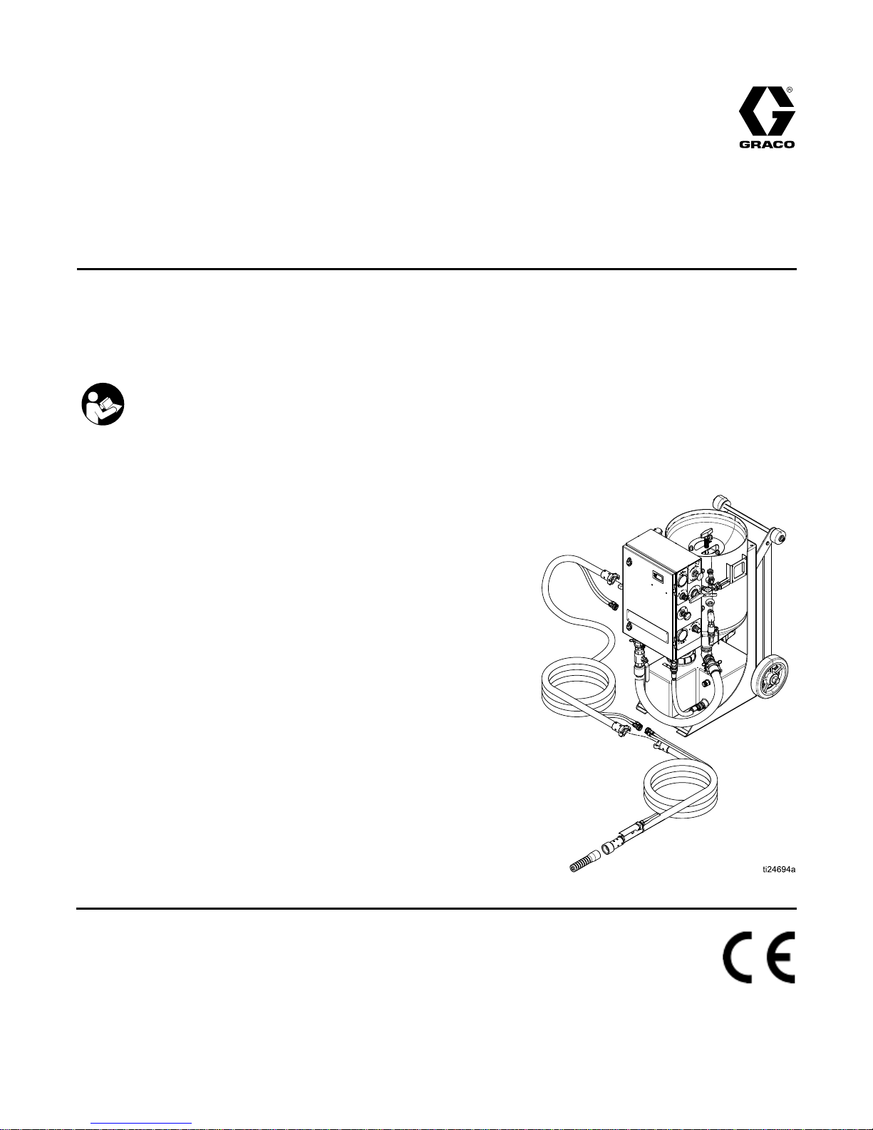
SystemComponentIdentication.........................8
EQ100M......................................................8
DataTrakControls........................................9
PressureReliefProcedure..................................10
Grounding(ATEXSystemsonly).........................10
Operation...........................................................11
ImportantNote.............................................11
ChecklistBeforeStarting..............................11
LiftingtheSystem........................................11
ConnectingtheBlastHoseandAir
Hose..............................................12
SettingUptheEquipment.............................13
BlastingTips................................................17
UsingtheWashFeature...............................19
RellingthePotwithAbrasive.......................20
ShuttingDown.............................................21
WinterizingtheEquipment............................23
Troubleshooting..................................................24
TroubleshootingExamples...........................27
Repair................................................................29
RepairingtheMainAirRegulator..................29
FlushingtheDiaphragmValve......................30
RepairingtheDiaphragmValve.....................31
CleaningtheAuto-VentValve.......................32
ReplacingtheDataTrakBattery....................33
ReplacingtheDataTrakFuse.......................34
Notes.................................................................35
Parts..................................................................36
EQ100MParts.............................................36
Enclosure....................................................38
PressurePot................................................40
BlastHoses.................................................41
HoseSchematic.................................................42
VaporAbrasiveBlastSystemsand
Accessories..........................................43
EcoQuipSystemCongurator.......................43
ModelSeries...............................................44
BlastHoseswithControlHose/Cables...........45
BlastHoseswithoutControl
Hose/Cables..................................45
BlastControlHoses/Cables..........................46
Nozzles.......................................................46
OtherAccessories........................................46
CommonSpareParts...................................47
Dimensions........................................................48
TechnicalSpecications......................................49
GracoExtendedWarrantyforEcoQuip™
Components.........................................50
2
334142F
Page 3

Models
Models Models
Models
Model Model
Model
Description Description
Description
Approvals Approvals
Approvals
EQ100MEcoQuip100VaporBlastSystem
EQ10XMEcoQuip100VaporBlastSystemATEXApproved
II 2G c ia IIA T3 X
Related Related
Related
Manuals Manuals
Manuals
Manual Manual
Manual
Number Number
Number
Product Product
Product
313840DataTrak
333397Pump
335035AirInletKit
334143
EQ300S,EQ600S
334666
EQ200T,EQ400T
334667
EQ300C,EQ600C
334142F3
Page 4
Warnings
Warnings Warnings
Warnings
Thefollowingwarningsareforthesetup,use,grounding,maintenance,andrepairofthisequipment.The
exclamationpointsymbolalertsyoutoageneralwarningandthehazardsymbolsrefertoprocedure-specic
risks.Whenthesesymbolsappearinthebodyofthismanualoronwarninglabels,referbacktothese
Warnings.Product-specichazardsymbolsandwarningsnotcoveredinthissectionmayappearthroughout
thebodyofthismanualwhereapplicable.
WARNING WARNING
WARNING
SPECIAL SPECIAL
SPECIAL
CONDITIONS CONDITIONS
CONDITIONS
FOR FOR
FOR
SAFE SAFE
SAFE
USE USE
USE
•Groundallequipmentintheworkarea.SeeGrounding Grounding
Grounding
Instructions Instructions
Instructions
.
•Alllabelandmarkingmaterialmustbecleanedwithadampcloth(orequivalent).
DUST DUST
DUST
AND AND
AND
DEBRIS DEBRIS
DEBRIS
HAZARD HAZARD
HAZARD
Useofthisequipmentcanresultinthereleaseofpotentiallyharmfuldustortoxicsubstances
fromtheabrasivebeingused,thecoatingsbeingremoved,andthebaseobjectbeingblasted.
•Foruseonlybysophisticatedusersfamiliarwithapplicablegovernmentalsafetyandindustrial
hygieneregulators.
•Useequipmentonlyinawell-ventilatedarea.
•Wearaproperlyt-testedandgovernmentapprovedrespiratorsuitableforthedustconditions.
•Followlocalordinancesand/orregulationsfordisposaloftoxicsubstancesanddebris.
4
334142F
Page 5
Warnings
WARNING WARNING
WARNING
EQUIPMENT EQUIPMENT
EQUIPMENT
MISUSE MISUSE
MISUSE
HAZARD HAZARD
HAZARD
Misusecancausedeathorseriousinjury.
•Donotoperatetheunitwhenfatiguedorundertheinuenceofdrugsoralcohol.
•Donotexceedthemaximumworkingpressureortemperatureratingofthelowestrated
systemcomponent.SeeTechnical Technical
Technical
Data Data
Data
inallequipmentmanuals.
•Donotusethisequipmentwithouthoserestraintsandcouplerpinsinstalledonallairand
blasthosecouplings.
•Donotblastunstableobjects.Thehighamountofuidowfromthenozzlecanpotentially
moveheavyobjects.
•Donotexceedloadratingoflifteyes.
•Donotoperateequipmentonorstandonanunstablesupport.Keepeffectivefootingand
balanceatalltimes.
•Useuidsandsolventsthatarecompatiblewithequipmentwettedparts.SeeTechnicalData
inallequipmentmanuals.Readuidandsolventmanufacturer’swarnings.Forcomplete
informationaboutyourmaterial,requestMSDSfromdistributororretailer.
•Donotleavetheworkareawhileequipmentisenergizedorunderpressure.
•TurnoffallequipmentandfollowthePressure Pressure
Pressure
Relief Relief
Relief
Procedure Procedure
Procedure
whenequipmentisnotinuse.
•Checkequipmentdaily.Repairorreplacewornordamagedpartsimmediatelywithgenuine
manufacturer’sreplacementpartsonly.
•Donotalterormodifyequipment.Alterationsormodicationsmayvoidagencyapprovals
andcreatesafetyhazards.
•Makesureallequipmentisratedandapprovedfortheenvironmentinwhichyouareusingit.
•Useequipmentonlyforitsintendedpurpose.Callyourdistributorforinformation.
•Routehosesandcablesawayfromtrafcareas,sharpedges,movingparts,andhotsurfaces.
•Donotkinkoroverbendhosesorusehosestopullequipment.
•Keepchildrenandanimalsawayfromworkarea.
•Complywithallapplicablesafetyregulations.
BURN BURN
BURN
HAZARD HAZARD
HAZARD
Equipmentsurfacesanduidthatisheatedcanbecomeveryhotduringoperation.Toavoid
severeburns:
•Donottouchhotuidorequipment.
FIRE FIRE
FIRE
AND AND
AND
EXPLOSION EXPLOSION
EXPLOSION
HAZARD HAZARD
HAZARD
Flammablefumes,suchassolvent,inwork work
work
area area
area
canigniteorexplode.Tohelppreventre
andexplosion:
•Useequipmentonlyinwellventilatedarea.
•Abrasivematerialexitingblastnozzlecangeneratesparks.Whenammableliquidsareused
neartheblastnozzleorforushingorcleaning,keeptheblastnozzleatleast20feet(6
meters)awayfromexplosivevapors.
•Keepworkareafreeofdebris,includingsolvent,ragsandgasoline.
•Keepaworkingreextinguisherintheworkarea.
334142F5
Page 6
Warnings
WARNING WARNING
WARNING
PERSONAL PERSONAL
PERSONAL
PROTECTIVE PROTECTIVE
PROTECTIVE
EQUIPMENT EQUIPMENT
EQUIPMENT
Wearappropriateprotectiveequipmentwhenintheworkareatohelppreventseriousinjury,
includingeyeinjury,hearingloss,inhalationoftoxicfumes,andburns.Protectiveequipment
includesbutisnotlimitedto:
•Protectiveeyewearandhearingprotection
•Protectiveclothing,shoes,andgloves
•Properlyt-testedandgovernmentapprovedrespiratorsuitableforthedustconditions
RECOIL RECOIL
RECOIL
HAZARD HAZARD
HAZARD
Blastnozzlemayrecoilwhentriggered.Ifyouarenotstandingsecurely,youcouldfalland
beseriouslyinjured.
6334142F
Page 7

Notes
Notes Notes
Notes
334142F
7
Page 8
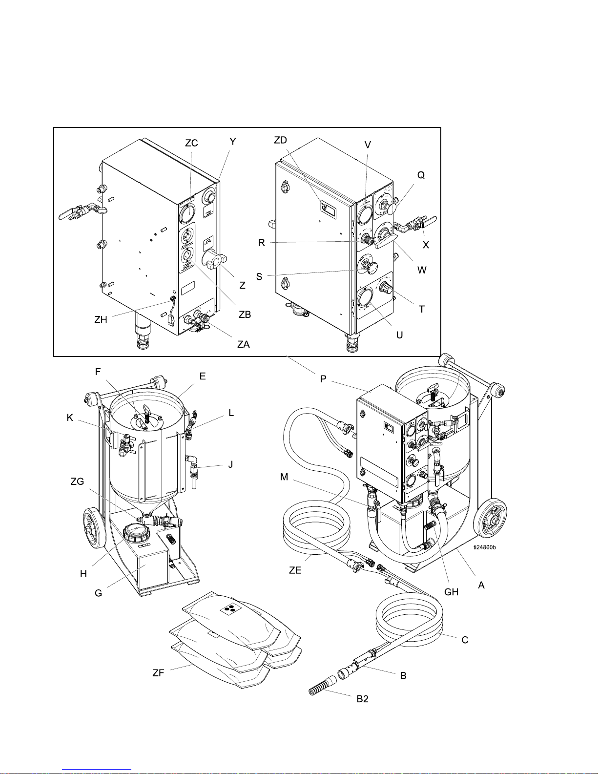
SystemComponentIdentication
System System
System
Component Component
Component
Identication Identication
Identication
EQ100M EQ100M
EQ100M
8334142F
Page 9
SystemComponentIdentication
Key: Key:
Key:
A
Cart
B
BlastControlSwitch
B2BlastNozzle
C
BlastHose
EPot
FPop-upPin
G
WaterTank
HWaterTankLid
JPotDumpValve
KAutoVentValve
L
BlastCheckValve
MAbrasiveBallValve
P
ControlBox
QEmergencyStop
RBlastAirRegulator
S
AbrasiveMeteringValve
TPotPressureRegulator
Key: Key:
Key:
U
PotPressureGauge
V
BlastAirPressureGauge
W
SelectorValve
XRinseBallValve
Y
AirSupplyConnection
Z
BlastConnection
ZA
PneumaticControlConnection
ZB
ElectricControlConnection(non-ATEX
systemsonly)
ZCSupplyAirPressureGauge
ZD
DataTrak(seeDataTrakControls,page9)
ZEAccessoryExtensionhose
ZFAbrasiveMaterial
ZG
FillPort
ZH
GroundWireandClamp(ATEXSystems
only)
GHGardenHoseConnection
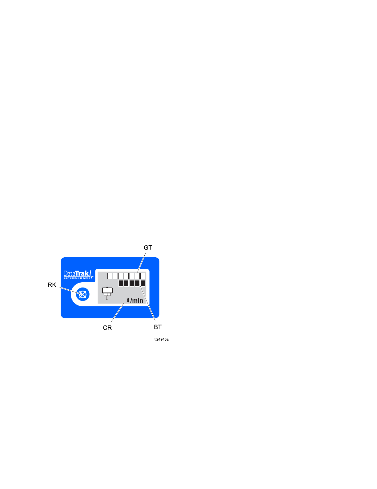
DataTrak DataTrak
DataTrak
Controls Controls
Controls
8800000
83000
9
Key: Key:
Key:
RK
ResetKey—Resultsinfaults.Pressand
holdforthreesecondstoclearthebatch
totalizer.
CRCycle/Rate
BTBatchTotalizer
GTGrandTotalizer
334142F9
Page 10
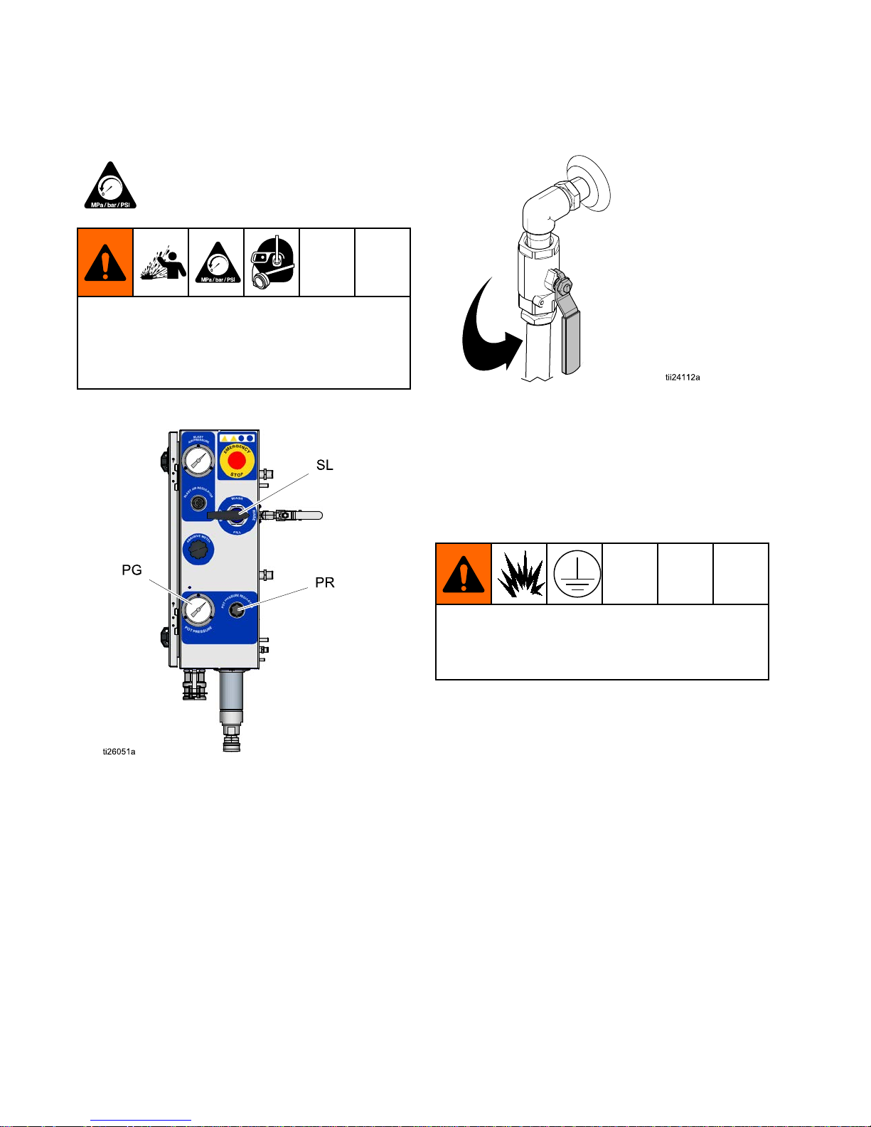
PressureReliefProcedure
Pressure Pressure
Pressure
Relief Relief
Relief
Procedure Procedure
Procedure
FollowthePressureReliefProcedure
wheneveryouseethissymbol.
Thisequipmentstayspressurizeduntilpressure
ismanuallyrelieved.Tohelppreventserious
injuryfrompressurizeduid,suchassplashing
uid,followthePressureReliefProcedurewhen
instructed.
1.Turnthepotpressureregulator(PR)off.
2.Closetheabrasiveballvalve.
3.Turnthecompressoroff.Closethecompressor
supplyairvalve.
4.Engagetheblastcontrolswitchtorelieve
pressureinthesystem.
5.Verifythatthesupplyairpressuregaugereads
0psi,thendisconnecttheairinlethosefromthe
system.
6.Turntheselectorvalve(SL)toFILL.
7.Openthedumpvalve.
8.Verifythatthepotpressuregauge(PG)displays
zeropressure.
Grounding Grounding
Grounding
(ATEX (ATEX
(ATEX
Systems Systems
Systems
only) only)
only)
Theequipmentmustbegroundedtoreducethe
riskofstaticsparking.Staticsparkingcancause
fumestoigniteorexplode.Groundingprovidesan
escapewirefortheelectriccurrent.
Systems: Systems:
Systems:
Usesuppliedgroundwireandclamp
(237686).
Air Air
Air
and and
and
uid uid
uid
hoses: hoses:
hoses:
UseonlygenuineGracoATEX
rated,conductivehoseswithamaximumof150ft
(45m)combinedhoselengthtoensuregrounding
continuity.Checktheelectricalresistanceofthe
hoses.Ifthetotalresistancetogroundexceeds29
megaohms,replacethehoseimmediately.
Air Air
Air
compressor: compressor:
compressor:
followmanufacturer’s
recommendations.
10334142F
Page 11

Operation
Operation Operation
Operation
Important Important
Important
Note Note
Note
Topreventfreezing,thisequipmentisshippedfrom
thefactorywithbluewindshieldwasheruidinside
thesystem.Itisnotnecessarytodrainbefore
using.Disposeoftheuidinaccordancewithlocal
regulations.
Checklist Checklist
Checklist
Before Before
Before
Starting Starting
Starting
•Checkthecompressedairsupplyaccordingtoits
operatormanual.Makesuretheairbeingsupplied
iscleanandrelativelyfreeofmoistureandoil
topreventwatercontaminationoftheaircontrol
components.
•Makesureairdeliveryvalvesareclosedbeforethe
airsupplycompressorisstarted.
•Makesureallrequiredhoserestraintsandcoupler
pinsareinworkingconditionandproperlyinstalled.
•Makesuretheequipmentissituatedonlevel
ground.Failuretokeeptheunitonlevelground
willmakeitdifcultorimpossibletopurgeallofthe
airfromthepressurevessel.
•Makesuretheequipmentisproperlysupportedon
asurfacethatcanholditstotalweight.Theweight
ofallpersonnel,thematerialbeingblasted,and
anyabrasivebeingstoredmustalsobeconsidered
(seeTechnicalSpecications,page49).
•Makesurethewatertankwillremainfullysupplied
withcleanwatertoavoidanypossibilityofthe
pumprunningdryduringblasting.
•Makesurethatthepotiscleanandfreeofany
internaldebris.
•Makesuretousethecorrecttypeofblastcontrol.
Anelectricorpneumaticblastcontrolswitchcan
beusedwithhoselengthslessthan150ft(45m).
Blastingwith150ft(45m)ormoreofblasthose
requirestheuseofanelectricblastcontrolswitch.
•Makesuretheblasthoseislaidoutasstraightas
possiblebetweentheequipmentandtheworksite
(acoiledblasthosewilluncoilunderpressure).
NOTICE NOTICE
NOTICE
Sharpbendsintheblasthosecouldcausethe
abrasivetowearthroughthehoseandcause
prematurefailureofthehose.
•Makesuretherubbergasketineachhosecoupler
isinworkingcondition.
Lifting Lifting
Lifting
the the
the
System System
System
•Liftthesystemwithaliftapparatusrated
appropriatelyfortheweightofthesystem(see
TechnicalSpecications,page49).
•Thesystemcanbeliftedusingtheliftringonthe
potorthecarthandle.
334142F
11
Page 12
Operation
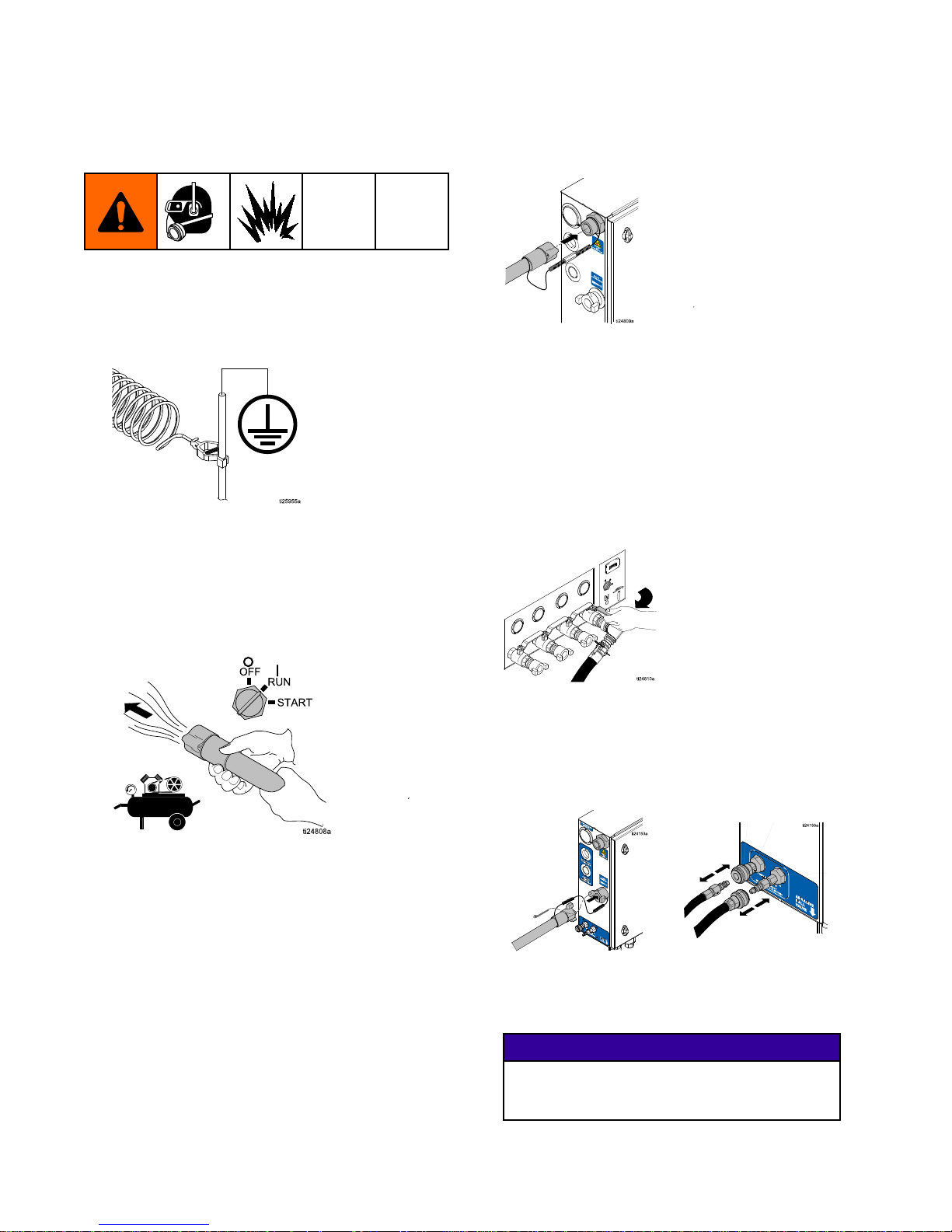
Connecting Connecting
Connecting
the the
the
Blast Blast
Blast
Hose Hose
Hose
and and
and
Air Air
Air
Hose Hose
Hose
1.EQ10XM EQ10XM
EQ10XM
Models Models
Models
only: only:
only:
Connectthegrounding
cabletotheexternalgroundstud(ZH)onthe
enclosure,thenconnecttheclamptoatrueearth
ground.
2.Alwayspurgetheairsupplyhose15–20seconds
beforeconnectingtheairsupplyhosefromthe
compressor(oron-sitecompressedairsource)
tothepanel.Makesurealldebrisisclearedfrom
thehose.
3.Connectanappropriatelysizedair
supplyhosetotheairinlet.See
TechnicalSpecications,page49.
NOTE: NOTE:
NOTE:
Makesuretoproperlyinstallhose
restraintsandcouplerpinstothequick-coupler
andtheairline.Iftheholesonthequick-coupler
donotalign,thereissomethingwrongandthe
twocouplersarenotcompatible.DO DO
DO
NOT NOT
NOT
TURN TURN
TURN
ON ON
ON
THE THE
THE
AIR AIR
AIR
.Seekhelptogetthesituation
resolved.
4.Opentheairsupplyvalve(125psi,8.6Bar,0.86
MPamaximum).Ifnecessary,usearegulatorin
thesupplyairlinetomeetthesespecications.
OFF
START
RUN
NOTE: NOTE:
NOTE:
Makesuretheairsupplymeets
theappropriate appropriate
appropriate
air air
air
ow ow
ow
requirements. requirements.
requirements.
See
TechnicalSpecications,page49.
5.Connecttheblasthose,hoserestraints,control
hoses,andcouplerpins.
NOTE: NOTE:
NOTE:
Ifyouareusinganelectricblastcontrol,
checkalloftheelectricalconnectionsfromthe
paneltotheblastcontrol.
NOTICE NOTICE
NOTICE
Makesurenoelectricalconnectionswillbeexposed
towater.Exposuretowatercouldcauseashort
circuitanddamagetheequipment.
12
334142F
Page 13
Operation
Setting Setting
Setting
Up Up
Up
the the
the
Equipment Equipment
Equipment
1.Disconnecttheabrasivehoseatthecamand
groovewiththeabrasiveballvalveclosed.
NOTE: NOTE:
NOTE:
Ifthepotcontainswaterandabrasive
(especiallyunderpressure),disconnectingthe
cam-lockwiththeballvalveopenwillcausean
unintentionalreleaseofabrasive.
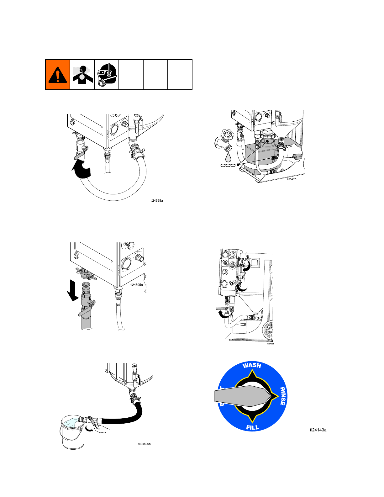
2.Flushwaterthroughthepotandoutofthe
disconnectedabrasiveballvalvebeforellingthe
potwithwaterandabrasive.
3.Reconnecttheabrasivehose.
4.Disconnectthepumpinlethoseandushthe
watertanktoremoveanyremainingdebris.
Reconnectthepumpinlethose.
5.Fillthewatertankonlywithfreshwater.Connect
hosewithatleasta3/4in.(19mm)IDfromwater
supplyto3/4in.gardenhoseinletonwatertank.
NOTE: NOTE:
NOTE:
Themaximumwatersupplypressureis
100psi(6.8bar,.068MPa).Useauidregulator
ifnecessary.
NOTE: NOTE:
NOTE:
Theminimumowrequirementis3gpm
(11lpm).
6.Closetherinse,dump,andabrasiveballvalves.
7.TurntheselectorvalvetoRINSE.
334142F13
Page 14
Operation
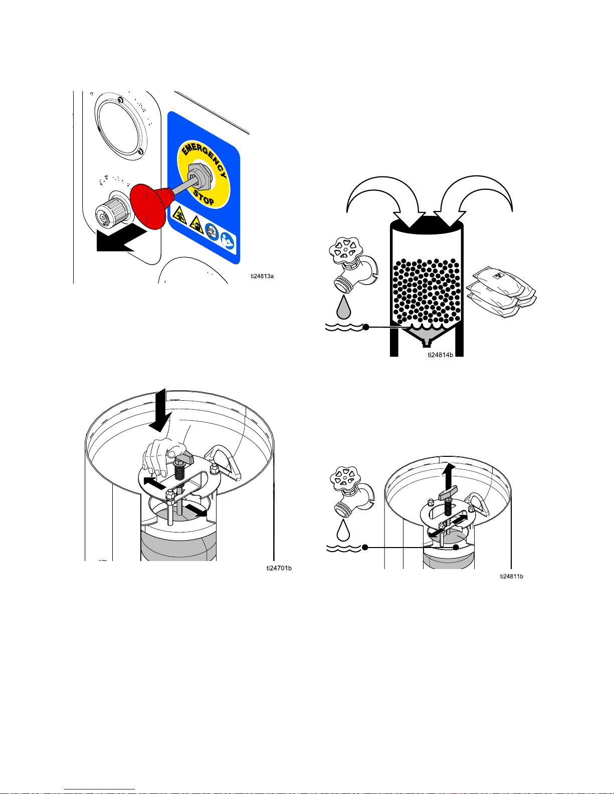
8.DisengagetheEmergencyStop.
NOTE: NOTE:
NOTE:
Thewaterpumpwillnotworkunlessthe
EmergencyStopisdisengaged.
9.Alignthepop-uphandlewiththepinslot,and
thenrmlypushandturnthehandle90°afterthe
pinisbelowthebracketslot.Properengagement
ofthepinwillholdthepop-updownuntilitis
released.
10.Add10gallons(30liters)offreshwaterto
thepot.Wearappropriatepersonalprotective
equipment,includingaproperlyt-tested
governmentapprovedrespiratorsuitableforthe
dustconditions.Addabrasivematerial(minimum
threebags,maximumve50lb(23kg)bagsof
high-massabrasive,orfour50lb(23kg)bags
oflowmassabrasive).
1
2
10 gal
(30 L)
150-250 lb
(68-113 kg)
11.Useagardenhoseortherinsehosetowashthe
abrasiveintothepotandclearanyabrasivefrom
thepop-upandgasket.
12.Whenthewaterlevelreachesthepop-upgasket,
rotatethehandletoreleasethepop-uppin.
NOTE: NOTE:
NOTE:
Makesurethepop-upgasketiscleanof
alldebris.
14
334142F
Page 15
Operation
13.TurntheselectorvalvetoFILL.
NOTE: NOTE:
NOTE:
Thewaterpumpshouldbegincycling.If
not,openthepotpressureregulatorenoughto
causethepumptorunat60cpm.
NOTE: NOTE:
NOTE:
Theautovent/purgevalvewillallowall
oftheairtrappedinthetopofthepottovent.
Whenairstopsventing,thepotpressuregauge
willstarttoregisterpressure.
14.Waitforpotpressuretoincrease.
NOTE: NOTE:
NOTE:
Itcantakeuptoseveralminutesforthe
pottopressurize.
ti24824a
NOTE: NOTE:
NOTE:
Thepop-upcannotbepusheddown
unlessallofthepressureinthepotisreleased
byopeningthedumpvalve.
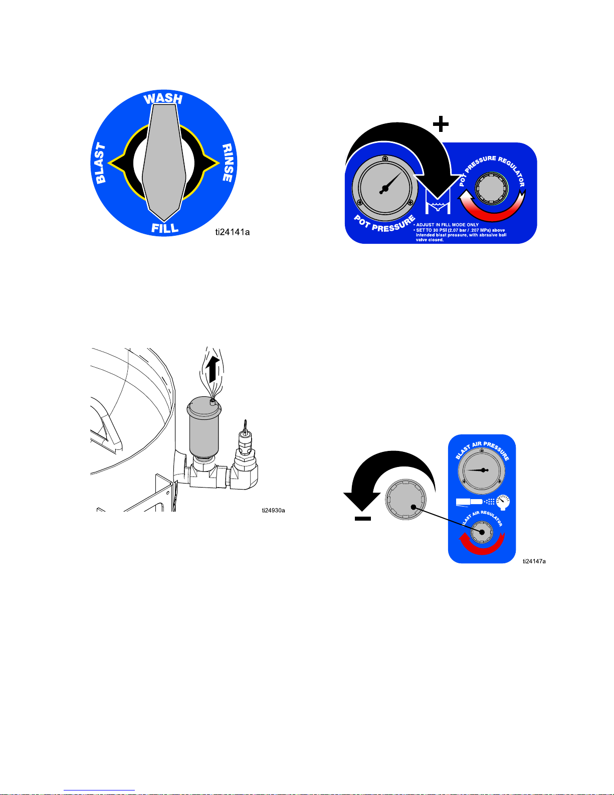
15.Setthepotpressure30psi(2.0Bar,0.2MPa)
higherthantheintendedblastpressure.Open
andclosethedumpvalveafterthepumpstalls.
Relievepotpressureto40psi(2.7Bar,0.27
MPa)beforeclosingthedumpvalve.Repeat
untilpotpressureisconsistent.
16.TurntheselectorvalvetoWASH.
17.Settheblastairpressure30psi(2.0Bar,0.2
MPa)lowerthanthepotpressurewhileblasting.
NOTE: NOTE:
NOTE:
Inordertoadjusttheblastpressure,
theblastcontrolswitchmustbeengaged.For
theinitialsetting,leavetheabrasiveballvalve
closed.
NOTE: NOTE:
NOTE:
Engageandreleasetheblastcontrol
switcheachtimetheblastregulatorisadjusted.
18.TurntheselectorvalvetoBLAST.
334142F15
Page 16

Operation
19.Opentheabrasiveballvalve.
NOTE: NOTE:
NOTE:
Makesurethepotpressurereturnstothe
initialsetting(itwillnotreturntotheinitialsetting
iftheabrasivemeteringvalveisclosed).
20.Engagetheblastcontrolswitchandbegin
blasting.
NOTE: NOTE:
NOTE:
Youmayhavetowait1–2minutesforthe
abrasivematerialtoreachthenozzle.
NOTE: NOTE:
NOTE:
Potpressureandblastpressureshould
equalizeduringblasting.Onlysetpotpressure
withtheabrasiveballvalveclosed.Neveradjust
potpressurewhileblasting.
21.Slowlyadjusttheabrasivemetervalvewhilethe
abrasiveisblastingfromthenozzle.Typical
adjustmentrangesfrom1/8to1/4turnopen.
NOTE: NOTE:
NOTE:
TheDataTrakcanbeusedtoassistin
settingthepumpcyclerate.Optimalabrasive
mediaconsumptiontypicallyoccurswiththe
cycleratesetat7–10cyclesperminute.
8800000
83000
9
NOTE: NOTE:
NOTE:
Useapieceoftestmaterialsimilarto
whatyouwillbeblasting.
NOTE: NOTE:
NOTE:
Alwaysstartasgentlyaspossibleand
thenincreasetheblastforceasnecessaryto
cleanwithoutdoinganydamagetothesubstrate.
Whenproperlyset,thepumpshouldcycle7-10
timesperminute.Highproductionrateusers
mayneedtoincreasecyclerateabove10cycles
perminute.
NOTE: NOTE:
NOTE:
Closetheabrasiveballvalvewhenever
youstopblastingformorethan20-30minutes.
Thiswillhelptoextendtheservicelifeofthe
diaphragmvalve.
16334142F
Page 17
Operation
Blasting Blasting
Blasting
Tips Tips
Tips
Whenrstlearningtheeffectsoftheblaster,geta
betterunderstandingoftheresultsbystartingata
shallowangle(closerto0°thanto90°)andkeep
thenozzleapproximately16in.(40cm)fromthe
application.Observetheresults,thenreducethe
distance,steepentheangle,andadjusttheblast
regulator.
Astheblastpressureisincreased,slowlyadjustthe
abrasivemeteringvalveandwatchtheDataTrak
toachieve7-10pumpcyclesperminute.See
DataTrakControls,page9.
NOTE: NOTE:
NOTE:
Theheavierandsmallertheabrasiveparticle
(i.e.80-grit),themoreaggressivetheresults.
Blasting Blasting
Blasting
on on
on
Higher Higher
Higher
Surfaces Surfaces
Surfaces
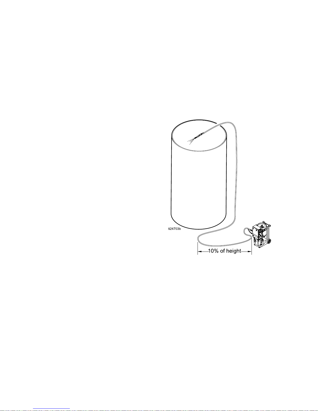
Whenblastingonasurfacehigherthanthe
equipment,makesurethatthereisalengthofblast
hoseonthegroundequalto10-20%oftheheight.
Thehoseonthegroundpreventsunspentabrasive
inthehosefromback-llingtheinternalplumbingof
thepanel.
Forexample:Whenblasting50feet(15m)straight
up,useatleast10feet(3m)ofblasthoseonthe
groundbeforetheblasthosegoesuptotheblasting
height.
334142F
17
Page 18

Operation
Abrasive Abrasive
Abrasive
Metering Metering
Metering
Valve Valve
Valve
Settings Settings
Settings
Thereisnoxedformulaforwhatworksbestineachapplication.Theinformationbelowworksbestforthe
majorityofthetime.Fromthisinitialsetting,adjustmentscanbemadeupordowntogetthefastestremoval
rateswithoutdamagetothesurface.
Normalsettingsare:110psi(7.5Bar,0.75MPa)initialpotsetting,lessthan1/2turnopenmeteringvalve,
blastingpressureat80psi(5.5Bar,0.55MPa).Forapplicationsrequiringhigherperformance,use
high-performanceabrasive(theheaviestmass@80grit)suchasGarnet,andthehighestpressuresthe
systemcansupport.Theinitialpotpressureshouldalwaysbe30psi(2.0Bar,0.2MPa)abovetheintended
blastpressure.
Graduallymakeadjustmentstomeetthespecicrequirementsforeachapplication.Makeadjustments(see
DataTrakControls,page9)toachieve7-10cyclesperminutetobethemostefcient(cutatthefastestrate
whileusingtheleastamountofabrasive).Blastingpressurescanrangebetween30-120psimax(2.0Bar,
0.2MPa–8.2Bar,0.82MPa).
Unlikeconventionalsandblasting,higherpressuresdonotnecessarilymeanbettercleaning.Nozzledistance
andtheangletothesurfacehasaneffectonperformance,asdoestheblastpressure.Choiceofabrasive
alsohasagreateffect.High-performanceabrasiveproducesthebestperformanceandcansaveenough
timetomakeupthedifferenceincost.
NOTE: NOTE:
NOTE:
Blastingwith150ft(45m)ormoreblasthoserequirestheuseofanelectricblastcontrol.
Grit Grit
Grit
Size Size
Size
Blast Blast
Blast
Pressure Pressure
Pressure
Abrasive Abrasive
Abrasive
Metering Metering
Metering
Valve Valve
Valve
Blast Blast
Blast
Angle Angle
Angle
Notes Notes
Notes
General General
General
40/70crushed
glass
60-80psi(4.1Bar,
0.41MPa-5.5Bar,
0.55MPa)
10cyclesper
minute
35°-65°
None
Wood Wood
Wood
80(usingalow
massabrasive
likecrushedglass
orwalnut)
40-50psi(2.7Bar,
0.27MPa-3.4Bar,
0.34MPa)
8cyclesper
minute
15°-30°
Donotwash,asit
mayraisethewood
grain.Brushoff
excessabrasiveafter
thewooddries.
Steel Steel
Steel
60–80(using
ahigh-mass
abrasivelike
Garnet)
100-120psi(6.8Bar,
0.68MPa-8.2Bar,
0.82MPa)
10–12cyclesper
minute
45°-65˚
None
Fiberglass Fiberglass
Fiberglass
40-70lowmass
45-65psi(3.1Bar,
0.31MPa-4.4Bar,
0.44MPa)
8cyclesper
minute
35°-45˚
None
NOTE: NOTE:
NOTE:
Adjustmentinblastpressurerequiresanadjustmentoftheabrasivemeteringvalve.
18334142F
Page 19

Operation
Using Using
Using
the the
the
Wash Wash
Wash
Feature Feature
Feature
Thewashfeaturecausesair-drivenwater(without
abrasive)torinseareasthathavealreadybeen
blastedwithabrasive.Itisalsoaconvenientfeature
forushingabrasivefromtheblasthose.
NOTICE NOTICE
NOTICE
Therewillalwaysbesomeresidualabrasivein
theblasthose.Neverusethewashfeatureon
anysurfaceotherthanwhereyouhaveblasted,or
intendtoblast.Itwillaffect/dullthesurface.
NOTICE NOTICE
NOTICE
Donotusethewashfeatureonwoodthathas
beenblasted.Itcoulddamagethewoodandcause
thegraintorise.Waitforthewoodtodryandthen
useabroom,brush,orvacuumtoremoveany
residualabrasive.
1.Closetheabrasiveballvalve.
2.TurntheselectorvalvetoWASH.
3.Blast1to2minutesuntiltheabrasiveiscleared
fromthehose.
4.Theequipmentisnowreadytowashany
previouslyblastedsurfaces.
334142F19
Page 20

Operation
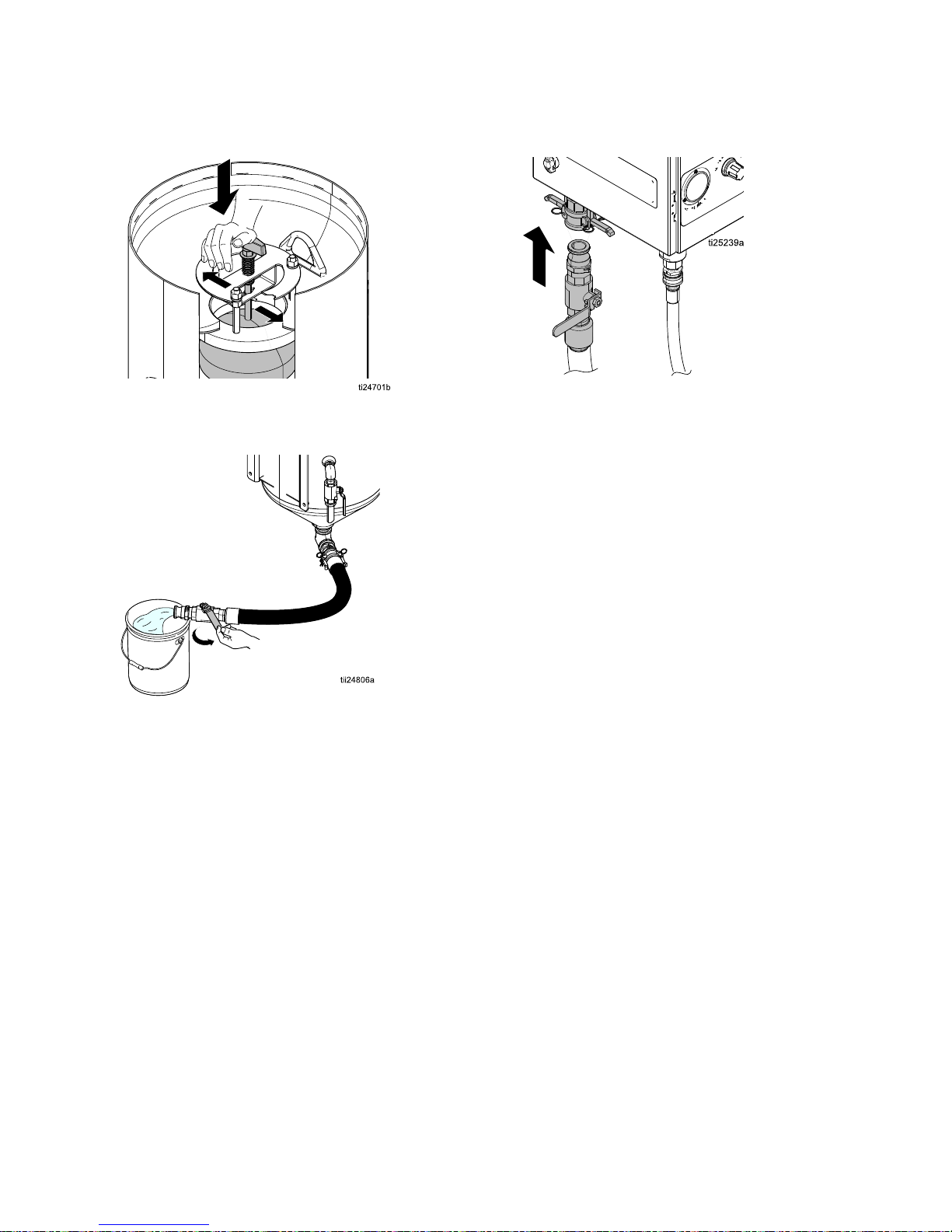
Relling Relling
Relling
the the
the
Pot Pot
Pot
with with
with
Abrasive Abrasive
Abrasive
1.Closetheabrasiveballvalve.
2.TurntheselectorvalvetoRINSE.
3.Openthedumpvalveslowlytorelievethewater
pressureinthepot.
NOTE: NOTE:
NOTE:
Bepreparedtocapturethewaterthat
willbedrainedfromthepot.Alldisposalsmust
complywithnational,state,andlocalregulations.
4.Afterallofthepressureinthepothasbeen
relieved,engagethepop-uppinbycompressing
thespringandturningthehandle90°toholdthe
pop-upintheopenposition.
5.Addtheabrasive(minimumthreebags,
maximumve50lb(23kg)bagsofhigh-mass
abrasiveorfour50lb(23kg)bagsoflow-mass
abrasive)andcontinuetheproceduresfrom
SettingUptheEquipment,page13.
NOTE: NOTE:
NOTE:
Morewatermayneedtobedrainedfrom
thepottoallowadditionalabrasivetobeadded.
20334142F
Page 21

Operation
Shutting Shutting
Shutting
Down Down
Down
1.Whenyouhavenishedblasting,performwash
untilalloftheabrasiveisushedfromtheblast
hose.SeeUsingtheWashFeature,page19.
2.TurntheselectorvalvetoRINSE,andwiththe
abrasiveballvalveclosed,continuetoblastuntil
waterisclearedfromthehose.Thisistodrythe
insideofthehoseforstorage.
3.Opentheabrasiveballvalve,thenopenthe
dumpvalveuntilthepotpressuregaugereads
0psi.Closetheabrasiveballvalveanddump
valve.Turnoffwatersupply.
NOTE: NOTE:
NOTE:
Short-termshutdownisnowcomplete.
Iftheuntilwillbeshutdownformorethan24
hours,proceedtothenextstep.
4.Disconnecttheabrasiveballvalvecam-lockby
removingthecouplerpinsandpullingtherings
outanduptopullthetwocamsawayfromthe
groove.
5.Holdabucketunderthecam-lockcoupler,then
turntheselectorvalvetoWASH.Thiswillclean
debrisfromthecam-lockcouplerandgasket.
NOTE: NOTE:
NOTE:
Makesurethegasketiscleanandin
placeaftertheprocedure.
NOTE: NOTE:
NOTE:
Besuretocatchtheunspentabrasive
thatwillbewashedoutofthepanelplumbing.
6.TurntheselectorvalvetoFILL.Thiswillhelp
pushtheabrasiveoutthroughtheabrasivehose.
7.Placeabucketundertheabrasivehose.Slowly
openandclosetheabrasiveballvalvetoush
abrasivematerialfromthepot.Repeatseveral
times.Oncenoabrasivematerialowsfromthe
hose,closetheabrasiveballvalve.
NOTE: NOTE:
NOTE:
Estimatethata5gallonpailwillbe
neededforeachbagofabrasivestillinthepot.
Coverthebucketsduringstoragesodebrisdoes
notcontaminatetheabrasive.
334142F
21
Page 22
Operation
8.Engagethepop-uppintoholdthepop-upopen
andallowairtoenter.
9.Opentheabrasiveballvalveandushthepotof
anyremainingabrasivematerial.
10.Closethepotpop-upandreconnecttheabrasive
hose.
NOTE: NOTE:
NOTE:
Thesystemmustbewinterizedifitwillbe
exposedtotemperaturesbelowfreezing.See
WinterizingtheEquipment,page23.
11.Turnoffthewatersupplyanddisconnect
thegardenhose.Relievepressure
tocompletesystemshutdown(see
PressureReliefProcedure,page10).
22
334142F
Page 23

Operation
Winterizing Winterizing
Winterizing
the the
the
Equipment Equipment
Equipment
Vapor-AbrasiveBlastersmustbewinterized
wheneverthereisapossibilityoffreezing
temperaturesduringstorage.Itisimperativethat
youanticipatethepossibilityofafreezeandalways
protecttheunitduringfallandwinterseasons,evenif
beingstoredonlyovernight.
1.Makesureallofthewaterhasbeendrained
fromthepot.Reconnecttheabrasivehoseafter
drainingthepot.
2.Makesurethepotpop-upisintheclosed
position.Thiswillpreventdebrisfromentering
thepotduringstorage.
3.Drainthewatertankbydisconnectingthepump
inlethose.Reconnectthepumpinlethoseafter
allwaterisdrainedfromthetank.
NOTE: NOTE:
NOTE:
Alldisposalsmustcomplywithnational,
state,andlocalregulations.Inaddition,ifthe
watercontainsarustinhibitor,youmaywantto
retainandpreservethewaterduetotheexpense
oftheinhibitor.
4.Chooseawindshieldwashwitharatingthat
willprotecttheequipmentforthelowest
temperaturesinyourarea.Addatleast2gallons
(7.5liters)ofwindshieldwashtothewatertank.
5.TurntheselectorvalvetoRINSEandopenthe
rinseball-valve.Whileholdingtherinsehose
overthepot,runthepumpuntilwindshieldwash
comesoutoftherinsehose.
6.Movetheselectorvalveintotheotherthree
positions(WASH,BLAST,andFILL).Conrm
thattheinternalwatertubingllswithwindshield
washbeforeturningtheselectorvalvetothenext
position.
NOTE: NOTE:
NOTE:
All3/8in.tubingshouldbelledwith
windshieldwashforfullprotection.
7.EngagetheE-stop.
8.Makesurethattherinseball-valveandthedrain
ball-valveareleftopen.
NOTICE NOTICE
NOTICE
Wheniceformsbehindtheseals,thesealscan
becomedamaged.Duringstorage,positionall
ball-valvesintheopenposition.
334142F23
Page 24

Troubleshooting
Troubleshooting Troubleshooting
Troubleshooting
Problem Problem
Problem
Cause Cause
Cause
Solution Solution
Solution
Theairsupplyisinadequate.Makesuretheairinletpressuregaugereads
100-125psi(6.8–8.6bar,0.68–0.86MPa).If
thegaugedoesnotread100–125psicheck
theaircompressorforpropersetup.
TheEmergencyStopis
engaged.
DisengagetheEmergencyStop.
Inadequatewatersupplyto
thepump.
Makesurethewatertankisfullandtheinlet
ballvalveisopen.
Thepotpressureregulatoris
settoolow.
Increasethesettingonpotpressureregulator.
Thepotpop-upcannotseal
properly.
Cleanallabrasivefromthepop-upandgasket.
Makesurethepop-upspringisliftingandthe
pop-upisrmlyagainsttheseal.Ifcleaning
doesnotsolveissue,replacepop-upgasket.
TheAuto-Ventvalvewillnot
seal.
SeeCleaningtheAuto-VentValve,page32.
Thepotpressurereliefvalve
isdischargingwater.
Decreasethepotpressureto145psi(10.3
bar,1.03MPa)orless.Ifthevalveweepsor
relievesat145psi,replacevalve.
Thepotorpumpisleaking
pressure.
Makesuretheabrasiveballvalveandthe
dumpvalveareclosed.Ifpotpressure
gaugestillcreepsdownward.See
CheckingforLeaks,page27.
Thepotwillnotproperly
pressurize.
Thepotpressureregulatoris
malfunctioning.
Replacethepotpressureregulatorassembly.
Theairsupplyisinadequate.Makesuretheairinletpressuregaugereads
100-125psi(6.8–8.6bar,0.68–0.86MPa).If
thegaugedoesnotread100–125psi,check
theaircompressorforpropersetup.
Theblastairregulatoris
malfunctioning.
Replacetheblastairregulator.
Theblastpressurewillnot
reachthedesiredsetpoint.
Themainairregulatoris
malfunctioning.
SeeRepairingtheMainAirRegulator,page29.
24
334142F
Page 25

Troubleshooting
Problem Problem
Problem
Cause Cause
Cause
Solution Solution
Solution
Thepotdoesnothavea
sufcientamountofabrasive.
SeeRellingthePotwithAbrasive,page20.
Thesystemisnotproperly
setup.
SeeSettingUptheEquipment,page13.
Makesurethepotpressureisproperlyset.
Thepotpressuremustbeset30psi(2bar,
0.2MPa)abovetheblastpressure.Make
suretheselectorvalveissettoBLAST.The
abrasiveballvalvemustbeopen.Theabrasive
meteringvalvemustbeatleast1/8turnopen.
Thereisanobstructioninthe
mediacircuit.
SeeFlushingtheDiaphragmValve,page30.
Thediaphragmvalveisnot
working.
SeeRepairingtheDiaphragmValve,page31.
Noabrasiveowsfromthe
nozzleduringblastmode.
Thereisblockageinsidethe
potorinsidetheabrasive
hosebetweenthepotand
thepanel.
Makesuretheballvalveisclosed,then
disconnectthecam-lockcoupler.Openthe
abrasiveballvalveslightlyandmakesure
abrasiveisowingfromtheabrasivehose.
Ifnot,followtheshutdownprocedure(see
ShuttingDown,page21).Thoroughlyushthe
potandthemediahoseafterdrainingmedia
andwater.
Theblastregulatorisnot
adjustedtothecorrect
pressure.
Adjusttheblastregulatortothedesired
pressurewhiletheblastcontrolisengaged.
Thetubingtothemainair
regulatorisnotproperly
connected.
Conrmthatthetubingfromtheblastregulator
tothemainairregulatorisintact.See
HoseSchematic,page42.
Theblastairregulatoris
malfunctioning.
Replacetheblastairregulator.
Noblastairowwhenthe
blastcontrolisengaged.
Thewaterpumpcycles
whiletheblastcontrol
engaged.
Themainairregulatoris
malfunctioning.
SeeRepairingtheMainAirRegulator,page29.
Theairsupplyisinadequate.Makesuretheairinletpressuregaugereads
100-125psi(6.8–8.6bar,0.68–0.86MPa).If
thegaugedoesnotread100–125psi,check
theaircompressorforpropersetup.
TheEmergencyStopis
engaged.
DisengagetheEmergencyStop.
Theelectricblastcontrol
circuitismalfunctioning.
Inspectthehosecablefordamagedorshorted
wiring.Checkthebatteryandcontrolpanel
connections.MakesuretheDCpowersource
is12V.Checkthe3Afuseinsidethecontrol
panel,andreplaceitifnecessary.Checkthe
currentowinthecircuit.Ifcurrentexists,
replacetherelay.
Noblastairowwhenthe
blastcontrolisengaged.
Thewaterpumpdoes does
does
not not
not
cyclewhiletheblastcontrol
engaged.
Thepneumaticblastcontrol
circuitismalfunctioning.
SeePneumaticBlastControlCircuit,page28.
334142F25
Page 26

Troubleshooting
Problem Problem
Problem
Cause Cause
Cause
Solution Solution
Solution
Themainairregulatoris
stuckopen.
SeeRepairingtheMainAirRegulator,page29.
Theblastcontroltubingis
notconnectedproperly.
Ensureairtubingisroutedandconnected
properly.SeeHoseSchematic,page42.
Electricblastcontrolcircuitis
malfunctioning.
Inspecthosecablefordamagedorshorted
wiring.Checkbatteryandcontrolpanel
connections.EnsureDCpowersourceis12V.
Check3Afuseinsidecontrolpanelandreplace
itifnecessary.Checkcurrentowincircuit,if
currentexists,replacerelay.
Theblastcontrolisnot
engagedbutblastingstill
occurs.
Pneumaticblastcontrol
circuitismalfunctioning.
SeePneumaticBlastControlCircuit,page28.
Incorrectabrasiveisbeing
used.
Usethecorrectabrasive.See
AbrasiveMeteringValveSettings,page18.
Thepotdoesnothavea
sufcientamountofabrasive.
Rellthepotwithabrasive.See
RellingthePotwithAbrasive,page20.
Thepotpressuresettingis
incorrect.
Performthepressurereliefprocedure(see
PressureReliefProcedure,page10)
andresetpotpressure(see
SettingUptheEquipment,page13).
TheAuto-Ventvalvedoes
notventairwhenthepotis
lled.
MakesuretheAuto-Ventvalveisworking.
PerformtheAuto-Ventcleaningprocedure
(seeCleaningtheAuto-VentValve,page32).
Thediaphragmvalveis
malfunctioning.
Performthediaphragmushprocedure(see
FlushingtheDiaphragmValve,page30).
Ifushingdoesnotsolveproblem,see
RepairingtheDiaphragmValve,page31.
Theblastspraypatternis
irregular.
Thereisblockageinsidethe
potorinsidetheabrasive
hosebetweenthepotand
thepanel.
Makesuretheballvalveisclosed,then
disconnectthecam-lockcoupler.Openthe
abrasiveballvalveslightlyandmakesure
abrasiveisowingfromtheabrasivehose.
Ifnot,followtheshutdownprocedure(see
ShuttingDown,page21).Thoroughlyushthe
potandthemediahoseafterdrainingmedia
andwater.
Theunitisnotonalevel
surface.
Placetheunitonalevelsurface.Ifthisis
impossible,theAuto-Ventmustbeonthe
highersideoftheunit.
Theinitialpotpressureisnot
setcorrectly.
Conrmthattheauto-ventvalveisworking
andsetinitialpotpressure30psi(2.0bar,0.2
MPa)abovetheblastpressure.
TheAuto-Ventis
malfunctioning.
Performauto-ventcleaningprocedure(see
CleaningtheAuto-VentValve,page32).
Astronghoserecoiloccurs
frequentlywhentheblast
controlswitchisengaged.
Thediaphragmneedstobe
ushed.
Performthediaphragmushprocedure(see
FlushingtheDiaphragmValve,page30).
Ifushingdoesnotsolvetheproblem,see
RepairingtheDiaphragmValve,page31.
26334142F
Page 27

Troubleshooting
Troubleshooting Troubleshooting
Troubleshooting
Examples Examples
Examples
Checking Checking
Checking
for for
for
Leaks Leaks
Leaks
1.Openthedumpvalve.Checkpotpressure
gauge,thenclosethedumpvalve.
Lookatthepressuregaugetoconrmthatall
pressurehasbeenrelievedfromthepot.
ti24825a
2.Disconnectthetubingattheblastcheckvalve(L)
andatthellportcheckvalve(ZG).
3.Makesurethepop-upisclosed.Turntheselector
valvetoWASH,thenopentheabrasiveballvalve
topressurizethepot.Setthepotpressureto145
psi(9.9Bar,0.99MPa).
4.Checkthewaterpumptoconrmthatnowater
isleakingfromtheTSLllport.
NOTE: NOTE:
NOTE:
Thepumpshouldstallafterthepot
pressurizes.Ifthepumpdoesnotstall,replace
theseals.Refertothepumpmanualforrepair
information.
5.Checkforanywaterleakingfromeithercheck
valve.Ifacheckvalveisleaking,itmustbe
repairedorreplaced.Ifthevalvesaredamaged,
thepotwillnotbeabletomaintainpressure.
Also,checkthepotpressurereliefvalve.Ifthe
valveisweepingatpotpressuresof145psior
less,itneedstobereplaced.
6.Closetheabrasiveballvalve,thenclosetheair
inletballvalve.Engagetheblastcontrolswitch
torelievepressureintheblastcircuit.Conrm
thatthesupplyairpressuregaugereads0psi.
7.Disconnectthequickcouplerandconrmthatthe
ballvalveisnotleaking.Replacetheabrasive
ballvalveifitisleaking.
334142F
27
Page 28

Troubleshooting
Pneumatic Pneumatic
Pneumatic
Blast Blast
Blast
Control Control
Control
Circuit Circuit
Circuit
1.AttheAir-Relay,disconnectthepush-to-connect
tubingandcheckthetriggercircuit(fromtheblast
controlhandle).
2.Withtheblastcontrolswitchactivated,conrm
thatthereisairowingfromthedisconnected
tube.
NOTE: NOTE:
NOTE:
Theairowshouldbeatsupplyair
pressurebuttheairvolumeisreduceddueto
thesizeofthettingsandtubing.Ifyoudonot
getsupplyairpressure,checktheblastcontrol
switchforproperoperation,andchecktheblast
controlhosestomakesuretheyarenotkinked
orinternallyblocked.
3.Checkthein-linelterattheindustrialinterchange
nippleconnectiononthesideofthepanel(where
youattachtheblastcontrolhose).
4.Ifthepreviousstepsdonotxtheissue,replace
theairrelay.
Pneumatic Pneumatic
Pneumatic
Blast Blast
Blast
Control Control
Control
— —
—
ATEX ATEX
ATEX
Approved Approved
Approved
Electric/Pneumatic Electric/Pneumatic
Electric/Pneumatic
Blast Blast
Blast
Control Control
Control
28334142F
Page 29

Repair
Repair Repair
Repair
Repairing Repairing
Repairing
the the
the
Main Main
Main
Air Air
Air
Regulator Regulator
Regulator
SeeEnclosurePartsList,page39forrepairkits.
1.PerformPressureReliefProcedure,page10.
2.Makesurealloftheairpressureisrelievedinthe
unit.Ifnecessary,removetheairlterforaccess
totheairregulator.
3.Removethepistoncover.
NOTE: NOTE:
NOTE:
Thereisaspringinsidethiscover.
4.Removethediaphragmcoverforaccesstothe
diaphragmandtotheendofthepistonshaft.
5.Removethediaphragmandinspectforany
cracksortears.Replacethediaphragmif
necessary.
6.Carefullyremovethespringandpistonassembly,
thencleanoutanydebrisinthebodyofthe
regulator.Makesurethewiremeshisfreeof
debris.
7.Inspectthepistonanditssealforanyforeign
matterthatmayhavebeenthecauseforthe
pistontostayopen.
8.Inspectforanydamagetothepistonshaftwhere
itinteractswiththediaphragmcup.Replace
componentswithexcessivewear.
334142F29
Page 30

Repair
Flushing Flushing
Flushing
the the
the
Diaphragm Diaphragm
Diaphragm
Valve Valve
Valve
Thisprocedurecanbeperformedwiththecomponent
stillmountedinthepanel.
Iflarge-gritabrasiveorotherforeignmatterbecomes
lodgedinthediaphragmvalve,itwillbecome
necessarytoushthevalve.Thisisasimple
procedure;however,itdoescausethereleaseofa
largevolumeofairtoescapethroughthereleased
quickcoupling.Youneedtobepreparedforthe
releaseofairbypullingthequickcouplergrommet
outofitsgroovesothatitdoesnotgetlost.
1.OperatetheunitinWASH(see
UsingtheWashFeature,page19)until
allabrasiveclearsfromtheblasthose.
2.Closetheabrasiveballvalve,thenturnthe
selectorvalvetoRINSE.Blastuntilthehoseis
clearofabrasiveandwater.
3.Disconnectthequickcouplingattheabrasive
ballvalve(notatthebottomofthepot).
4.TurntheselectorvalvetoWASH.Remainin
WASHuntilalldebrisisclear.Removethe
grommetintheguidecoupler.
5.Makesurenothingisinthepathoftheopen
quickcoupler,thenengagetheblastcontrol
switchbrieyandseveraltimes.
NOTE: NOTE:
NOTE:
Highowairshouldescapethroughthe
cam-lockcoupling.Ifthisdoesnotoccur,the
diaphragmvalveismalfunctioning.Replace
entirediaphragmcanister.
NOTE: NOTE:
NOTE:
Donotdisassemblethecanister.
6.Holdthemaleendofthequickcouplerupto
thewatercomingfromthecam-lockendofthe
coupler.Cleanoffanydirtorabrasive.
7.TurntheselectorvalvetoRINSEtostoptheow
ofwater.
8.Re-insertthegrommetintoitsinternalgroove
insidethecam-lock.
9.Reconnectthequickcoupler.Ifproperlycleaned
andconnected,thereshouldbenoleaksatthe
couplerduringoperation.
30334142F
Page 31

Repair
Repairing Repairing
Repairing
the the
the
Diaphragm Diaphragm
Diaphragm
Valve Valve
Valve
SeeEnclosurePartsList,page39forrepairkits.
NOTE: NOTE:
NOTE:
Thediaphragmcanbereplacedwithout
removingtheassemblyfromthepanel.Youwillneed
a6mmAllenwrench.
1.PerformthePressureReliefProcedure,page10.
2.Applymorethan80psi(5.5Bar,MPa)air
pressuretotheregulatorinlettocausethepiston
toretract.
3.Loosenall4Allen-headcap-boltsevenlyand
thenremovethemcompletelywhilesupporting
thecanisterofthediaphragmvalve.
NOTE: NOTE:
NOTE:
Donotdisassemblethecanister.
4.Replacethediaphragm(naturalrubber
compound)andhand-tighten(onlyasfaras
necessary)toestablishthealignmentwiththe
canister.
NOTE: NOTE:
NOTE:
Thereisoneshimbetweenthediaphragm
andtheactuator.Keeptheshimandreuseit(it
doesnotcomewiththereplacementdiaphragm).
Donotcauseanypre-loadortorqueonthe
diaphragmbyover-tighteningitinamisaligned
position.
5.Insertall4Allen-headcapboltsandhand-tighten.
6.Tightenthecap-boltsinanalternatingpattern
(seeimagebelow)to80+/-8in-lb(9+/-0.9N•m).
Thiswillcauseaslightbulgeinthediaphragm
betweenthecanisterandthestainlesssteel
casting.
1
2
3
4
7.Relievethepressureappliedinstep2.
8.Testandconrmthattheunitisworkingproperly.
NOTE: NOTE:
NOTE:
Thiscanbedoneusingonlywaterto
chargetheequipment–thereisnoneedtouse
abrasiveforthistest.
334142F31
Page 32

Repair
Cleaning Cleaning
Cleaning
the the
the
Auto Auto
Auto
- --Vent Vent
Vent
Valve Valve
Valve
Afterthepop-uphasbeenclosedwhilellingthepot,
theauto-ventvalveshouldreleaseair(youshouldbe
abletoheartheairventing).
Thepotpressuregaugewillnotshowpressureuntil
theauto-ventvalvehasbledalloftheairandsealed.
Iftheauto-ventvalvedoesnotreleaseair,orifwater
leaksfromthestemduringthellprocess,thestem
valvemaybecloggedorfaulty.
Performthefollowingproceduretocleanaclogged
auto-ventvalve.
1.Trytopushandquicklyreleasethevalvewith
yournger.Ifthatdoesnotcausethevalveto
seal,openthedumpvalvetoreleaseallofthe
pressureinthepot.
2.Openthedumpvalvetorelievepotpressure.
Openthepop-upanddrainthepotuntilthewater
levelisbelowthepop-up.
3.TurntheselectorvalvetoRINSE.
4.Usetherinsehosetoforcewaterbackwardsinto
thevalvestem.
NOTE: NOTE:
NOTE:
Ifthepreviousstepsfailtoresolvethe
issue,replacethewholevalveassembly.
NOTICE NOTICE
NOTICE
Thevalvestemitselfisinternallyattachedtothe
oatanditisnoteld-serviceable.Donottryto
removethevalvestem.Damagetotheequipment
willoccur.
32334142F
Page 33

Repair
Replacing Replacing
Replacing
the the
the
DataTrak DataTrak
DataTrak
Battery Battery
Battery
FIRE FIRE
FIRE
AND AND
AND
EXPLOSION EXPLOSION
EXPLOSION
HAZARD HAZARD
HAZARD
Toreducetheriskofreandexplosion,thebattery
mustbereplacedinanon-hazardouslocation.
Useonlyanapprovedreplacementbattery(see
table).Useofanunapprovedbatterywillvoid
Graco’swarranty.
Replace Replace
Replace
Battery Battery
Battery
1.Unscrewcablefromthebackofthereedswitch
assembly.
2.Removethecablefromthetwocableclips.
3.RemovetheDataTrakmodulefromthebracket.
Takethemoduleandattachedcabletoa
non-hazardouslocation.
4.Removethetwoscrewsonthebackofthe
moduletoaccessthebattery.
5.Disconnecttheusedbatteryandreplaceitwith
anapprovedbattery.
Approved Approved
Approved
Batteries Batteries
Batteries
Energizeralkaline#522
Vartaalkaline#4922
Ultralifelithium#U9VL
Duracellalkaline#MN1604
334142F33
Page 34

Repair
Replacing Replacing
Replacing
the the
the
DataTrak DataTrak
DataTrak
Fuse Fuse
Fuse
FIRE FIRE
FIRE
AND AND
AND
EXPLOSION EXPLOSION
EXPLOSION
HAZARD HAZARD
HAZARD
Toreducetheriskofreandexplosion,thefuse
mustbereplacedinanon-hazardouslocation.
Useonlyanapprovedreplacementfuse(see
table).UseofanunapprovedfusewillvoidGraco’s
warranty.
Replace Replace
Replace
Fuse Fuse
Fuse
1.Removethescrew,metalstrap,andplastic
holder.
2.Pullthefuseawayfromtheboard
3.Replacewithanapprovedfuse.
Approved Approved
Approved
Fuses Fuses
Fuses
DataTrak DataTrak
DataTrak
Part Part
Part
Number Number
Number
*Series *Series
*Series
Letter Letter
Letter
Fuse Fuse
Fuse
Required Required
Required
AorB
24C580
289822
Candlater
24V216
A
24C580
Allotherpart
numbers
Bandlater24V216
34334142F
Page 35

Notes
Notes Notes
Notes
334142F35
Page 36

Parts
Parts Parts
Parts
EQ100M EQ100M
EQ100M
Parts Parts
Parts
9
Applyanti-seizetostuds.Torqueto25–30ft-lb(34–40N•m).
36334142F
Page 37

Parts
EQ100M EQ100M
EQ100M
Parts Parts
Parts
List List
List
Ref. Ref.
Ref.
Part Part
Part
Description Description
Description
Qty. Qty.
Qty.
2
EQ1840HOSE,clear,braided,
3/8in.ID
5ft
424X773KIT,replacement,
watertankassembly
1
5*EQ1907CAP,ventedwater
tanklid
1
6*
24X775
KIT,oatvalve
assembly
1
7*
128193
WASHER,ber
1
8*EQ1846COUPLER,
interchange,
straight-thr
1
10
17C032HOSE,inlet,water
1
11
–––––
PRESSUREPOT,
assy,2.0cf
1
12
EQ5183CABLE,battery,
electricblastcontrol
1
13
EQ1943HOSE,abrasive
media,1–1/4in.ID
1
14128226
NUT,ange,3/8–16
sst
4
15*
128194NUT,lock,1/2NPT,
brass
1
16*
128192
COUPLER,swivel,3/4
FGHTx1/2NPT
1
17*
128191
ADAPTER,QDset,
gardenhose
1
Ref. Ref.
Ref.
Part Part
Part
Description Description
Description
Qty. Qty.
Qty.
19
–––––
ENCLOSURE,blast,1
in.npt
1
2017D786KIT,replacement,hose
restraint
1
25123002
FITTING
1
26
EQ1931
ADAPTER,cam
groove,typeF,ss
1
28
EQ1273HOSE,tubing,natural,
3/8in.OD
4ft
33
EQ1881HOSE,tubing,natural,
1/4in.OD
1ft
35
–––––
LABEL,EQ100M,
branding
1
41206994
FLUID,TSL,8oz.
bottle
1
43
EQ5149
VALVE,abrasive
media,1–1/4in.
1
4417D787KIT,replacement,
couplerpin
1
▲4517F870LABEL,warning1
46
EQ1866FITTING,groundboss,
spud,1–1/4in.
1
*
Includedinassembly4.
▲
ReplacementDangerandWarninglabelsare
availableatnocost.
334142F37
Page 38

Parts
Enclosure Enclosure
Enclosure
12
Torquettingto35–40ft-lb(47–54N•m).
38334142F
Page 39

Parts
Enclosure Enclosure
Enclosure
Parts Parts
Parts
List List
List
Ref. Ref.
Ref.
Part Part
Part
Description Description
Description
Qty. Qty.
Qty.
1
17C132
KIT,repair,regulator,air1
2
17C133
KIT,gauge,airreulator3
3
17C625
KIT,regulator,blast1
4
EQ5178
KIT,e-stop,1/4npt1
5
EQ5179□
RELAY,airpilot,electric/pneumatic
blastcontrol
1
EQ7199♦
RELAY,airpilot,pneumaticblast
control
1
6
EQ5163KIT,manifold
1
7
EQ5112
KIT,blastcontrol,return1
8
EQ5113
KIT,blastcontrol,output1
9
EQ5181
VALVE,selector,5–way1
10
EQ5160
VALVE,needle,dose1
11125420
FITTING,bulkhead,M14x1/4in.tube
1
12
EQ1115
BULKHEAD,connector,union3/8in.2
14111639
SCREW,cap,hex,hd
4
15127918
NUT,ange,serrated,M5
4
▲16
17F870
LABEL,safety
1
17127917
NUT,ange,serrated,1/4–20,ss
5
18
–––––
ENCLOSURE,ssel,24in.x16in.x
8in.
1
19
EQ1527□FITTING,holder,fuse,atmtype
1
20
EQ1844□FUSE,atm,bladetype,3amp
1
22127929□
SCREW,sems,#6–32,3/8in.,sst
22
127929♦
SCREW,sems,#6–32,3/8in.,sst
18
23127932
SCREW,sems,#10–32,1–1/2in.,sst
2
24127908
NUT,ange,serrated,#10–32,ss
4
25
EQ1790□PLUG,angedinlet,twistlock
1
128142♦
PLUG,hole,snap-in,1–3/4in.
1
26
EQ1791□CONNECTOR,twist-lock,anged,2P,
F
1
128142♦
PLUG,hole,snap-in,1–3/4in.
1
33
EQ1121FITTING,elbow,stem1/4in.
5
37121022
FITTING,elbow,male,1/4innpt
1
38
–––––
KIT,blast,plumbing,1in.npt1
39
EQ1846COUPLER,interchange,straight-thr
1
41
–––––
GASKET,enclosure
2
42
–––––
GASKET,100,enclosure
2
Ref. Ref.
Ref.
Part Part
Part
Description Description
Description
Qty. Qty.
Qty.
4317B912
GROMMET,pump,mounting
1
44
EQ1840HOSE,clear,braided,3/8in.ID2ft
4517H164KIT,spacer,bc,1001
4717D685KIT,replacement,doorlatch2
49
–––––
BRACKET,DataTrak
1
50
–––––
GASKET,DataTrak
1
5124A592KIT,DataTrak,smarts,cyclecount
only
1
53
–––––
FITTING,nipple,reducing,sst
1
55
EQ1335COUPLER,sandblast,tank,brass,
1–1/4in.
1
56
EQ1867COUPLER,camlocktypeD,ss1–1/4
1
59111799
SCREW,cap,hex,hd
2
60
EQ5175KIT,airlter,1/4in.tube,withlter
1
6124V672PUMP,sst,3:11
62
–––––
BRACKET,pump
1
63127846
FITTING,elbow,push-to-connect,1/2
in.
1
66
–––––
FITTING,adapter
1
67
–––––
SPACER,washer,shim,ss
AR
68
EQ5119REGULATOR,xed,80psi
1
69
–––––
SPACER,washer,shim,ss
AR
70
EQ5223
KIT,washvalveassembly1
72100985♦
WASHER,lockext
1
73194337♦WIRE,grounding,door1
▲75
186620♦LABEL,groundsymbol3
76237686♦WIRE,groundassemblywithclamp1
77
555629♦
WASHER,#10externaltoothlock
2
7816P265♦LABEL,warning,explosion1
80
–––––
REGULATOR,air
1
17C129
KIT,repair,major
81
–––––
VALVE,diaphragm1
17C127
KIT,repair
17F505KIT,canister
□Fornon-ATEXapprovedsystems
♦ForATEXapprovedsystems
▲
ReplacementDangerandWarninglabelsareavailableatno
cost.
334142F39
Page 40

Parts
Pressure Pressure
Pressure
Pot Pot
Pot
Pressure Pressure
Pressure
Pot Pot
Pot
Parts Parts
Parts
List List
List
Ref. Ref.
Ref.
Part Part
Part
Description Description
Description
Qty. Qty.
Qty.
125A056
PRESSUREPOT,blast,
2.0cubicft.
1
224X765KIT,pressurepot,check
valve
1
324X766KIT,pressurepot,dump
valve
1
424X767KIT,pressurepot,
auto-vent
1
5
16G247FITTING,1/2nptx3/8in.
tube
1
6
EQ5148
KIT,pressurepot,unequal
tee
1
7
EQ1360HOSE,clear,braided,3/4
in.ID
3ft
8#
17D790KIT,replacement,
handwaygasket
1
9#
24X764KIT,replacement,pop-up
head,6in.
1
10#
17F065KIT,replacement,pop-up
gasket,6in.skirt
1
Ref. Ref.
Ref.
Part Part
Part
Description Description
Description
Qty. Qty.
Qty.
11#
24X768KIT,replacement,
alignmentbracket
1
12#
24X770KIT,replacement,pop-up
T-handle
1
13*EQ1860
VALVE,auto-vent,3/4npt1
14*
127699
VALVE,safety,150psi
1
15†
EQ1034
VALVE,check,3/8in.sst1
16†127852
FITTING,elbow,swivel,
push-to-connect
1
17‡
EQ1003
VALVE,ball,3/4npt,sst1
#
Includedinassembly1
†
Includedinassembly2
‡
Includedinassembly3
*
Includedinassembly4.
1
Applysealanttopipethreads.
40334142F
Page 41

Parts
Blast Blast
Blast
Hoses Hoses
Hoses
EQ5234 EQ5234
EQ5234
EQ5235 EQ5235
EQ5235
EQ5236 EQ5236
EQ5236
EQ5237 EQ5237
EQ5237
Ref. Ref.
Ref.
Part Part
Part
Description Description
Description
Qty. Qty.
Qty.
1
EQ1843*HOLDER,nozzle,nylon
1
128616
HOLDER,nozzle,brass
1
2
EQ1842*COUPLER,blasthose,
nylon
1
128617
COUPLER,blasthose,
brass
1
3
17D791*
HANDLE,blast,control
switch,electric
1
17D788HANDLE,blast,control
switch,pneumatic
1
4
-----
(seeBlastControlHoses/Cables,
page46)
5
-----
(seeBlastHoseswithControl
Hose/Cables,page45)
617H239
KIT,screws,fh,sst,8pk
1
7
17H240KIT,cableties,6pk1
8
17C459*GASKET,nylonblast
coupler
1
17C124GASKET,brassblast
coupler
1
917D786KIT,replacement,
whipcheck
1
1017D787KIT,replacement,hairpin,
hose
1
*
Non-ATEXsystemsonly
334142F
41
Page 42

HoseSchematic
Hose Hose
Hose
Schematic Schematic
Schematic
Ref. Ref.
Ref.
Part Part
Part
Color, Color,
Color,
Tube Tube
Tube
Size Size
Size
Cut Cut
Cut
Length Length
Length
1
EQ1296Orange,1/4in.OD
7.0in.
2
EQ1882Red,1/4in.OD
3.0in.
3
EQ1273Natural,3/8in.OD
6.0in.
4
EQ1273Natural,3/8in.OD
1.5in.
5
EQ1273Natural,3/8in.OD
3.0in.
6
EQ1273Natural,3/8in.OD
22.0in.
7
EQ1882Red,1/4in.OD
16.0in.
8
EQ1882Red,1/4in.OD
18.0in.
9
EQ1881Natural,1/4in.OD
21.0in.
Ref. Ref.
Ref.
Part Part
Part
Color, Color,
Color,
Tube Tube
Tube
Size Size
Size
Cut Cut
Cut
Length Length
Length
10
EQ1883Blue,1/4in.OD
15.0in.
11
EQ1883Blue,1/4in.OD
18.0in.
12
EQ1884Green,1/4in.OD
9.0in.
13
EQ1884Green,1/4in.OD
4.0in.
14
EQ1884Green,1/4in.OD
14.0in.
15
EQ1884Green,1/4in.OD
16.0in.
16
EQ1885Yellow,1/4in.OD
14.0in.
17
EQ1885Yellow,1/4in.OD
7.0in.
18
EQ1275Natural,1/2in.OD
14.0in.
42
334142F
Page 43

VaporAbrasiveBlastSystemsandAccessories
Vapor Vapor
Vapor
Abrasive Abrasive
Abrasive
Blast Blast
Blast
Systems Systems
Systems
and and
and
Accessories Accessories
Accessories
EcoQuip EcoQuip
EcoQuip
System System
System
Congurator Congurator
Congurator
Model Model
Model
Series Series
Series
Trailer Trailer
Trailer
Option Option
Option
Package Package
Package
(blast (blast
(blast
hose hose
hose
and and
and
nozzle) nozzle)
nozzle)
Conguration Conguration
Conguration
EQ EQ
EQ
3 3
3
0 0
0
X X
X
S S
S
EQ
1=100
0=Non-Trailer(100,
300,600Series)
0=Barepackage(noblasthoseor
nozzle)
3=Tier3compliant
compressor(400Series)
2=200E=Electricbrakes
(200,400Series)
E=Completepackage,electricblast
control,includes15m(50ft)blast
hoseandnozzle
4=Tiercompliantcompressor
(200,400Series)
3=300H=Hydraulicbrakes
(200Series)
P=Completepackage,pneumatic
blastcontrol,includes15m(50ft)
blasthoseandnozzle
C=Nocrashframeorwater
tank(300,600Series)
4=400
X=Completepackage,ATEX
approved,includes15m(50ft)blast
hoseandnozzle(100,300,600
Series)
M=Mobileunit(100Series)
6=600
S=Skidunit(300,600Series)
Accessory: Accessory:
Accessory:
Air Air
Air
Inlet Inlet
Inlet
Ball Ball
Ball
Valve/Strainer Valve/Strainer
Valve/Strainer
Kit Kit
Kit
24X419–1.25in.kit(100,300series)
24X420–1.50in.kit(600series)
*Includedinrepairkit17G019.
334142F43
Page 44

VaporAbrasiveBlastSystemsandAccessories
Model Model
Model
Series Series
Series
Part Part
Part
Description Description
Description
100 100
100
Series Series
Series
EQ100M
Barepackage,mobileunit
EQ10EMCompletepackage,electricblastcontrol,mobileunit
EQ10PMCompletepackage,pneumaticblastcontrol,mobileunit
EQ10XMCompletepackage,pneumaticblastcontrol,ATEXapproved,mobileunit
300 300
300
Series Series
Series
EQ300SBarepackage,skid/crashframeandwatertank
EQ300CBarepackage,noskid/crashframeorwatertank
EQ30ESCompletepackage,electricblastcontrol,skid/crashframeandwatertank
EQ30ECCompletepackage,electricblastcontrol,noskid/crashframeorwatertank
EQ30PSCompletepackage,pneumaticblastcontrol,skid/crashframeandwatertank
EQ30PCCompletepackage,pneumaticblastcontrol,noskid/crashframeandwatertank
EQ30XSCompletepackage,pneumaticblastcontrol,ATEXapproved,skid/crashframeandwatertank
EQ30XCCompletepackage,pneumaticblastcontrol,ATEXapproved,noskid/crashframeandwatertank
600 600
600
Series Series
Series
EQ600SBarepackage,skid/crashframeandwatertank
EQ600CBarepackage,noskid/crashframeorwatertank
EQ60ESCompletepackage,electricblastcontrol,skid/crashframeandwatertank
EQ60ECCompletepackage,electricblastcontrol,noskid/crashframeorwatertank
EQ60PSCompletepackage,pneumaticblastcontrol,skid/crashframeandwatertank
EQ60PCCompletepackage,pneumaticblastcontrol,noskid/crashframeandwatertank
EQ60XSCompletepackage,pneumaticblastcontrol,ATEXapproved,skid/crashframeandwatertank
EQ60XCCompletepackage,pneumaticblastcontrol,ATEXapproved,noskid/crashframeandwatertank
200 200
200
Series Series
Series
Trailers Trailers
Trailers
EQ2E04
Barepackage,electricbrakes,Tier4i
EQ2EE4Completepackage,electricblastcontrol,electricbrakes,Tier4i
EQ2EP4Completepackage,pneumaticblastcontrol,electricbrakes,Tier4i
EQ2H04
Barepackage,hydraulicbrakes,Tier4i
EQ2HE4Completepackage,electricblastcontrol,hydraulicbrakes,Tier4i
EQ2HP4Completepackage,pneumaticblastcontrol,hydraulicbrakes,Tier4i
400 400
400
Series Series
Series
Trailers Trailers
Trailers
EQ4E03
Barepackage,electricbrakes,Tier3
EQ4EE3Completepackage,electricblastcontrol,electricbrakes,Tier3
EQ4EP3Completepackage,pneumaticblastcontrol,electricbrakes,Tier3
EQ4E04
Barepackage,electricbrakes,Tier4i
EQ4EE4Completepackage,electricblastcontrol,electricbrakes,Tier4i
EQ4EP4Completepackage,pneumaticblastcontrol,electricbrakes,Tier4i
100,200,300Seriescompletepackagesinclude1.0in.ID4–plyhoseand#7standardnozzle.
400,600Seriescompletepackagesinclude1.25in.ID2–plyhoseand#8performancenozzle.
44
334142F
Page 45

VaporAbrasiveBlastSystemsandAccessories
Blast Blast
Blast
Hoses Hoses
Hoses
with with
with
Control Control
Control
Hose/Cables Hose/Cables
Hose/Cables
Part Part
Part
ID ID
ID
Blast Blast
Blast
Control Control
Control
Coupler Coupler
Coupler
1 1
1
Coupler Coupler
Coupler
2 2
2
Length Length
Length
Models Models
Models
ATEX ATEX
ATEX
Approved Approved
Approved
EQ5237
1.0in.Pneumatic2–Prongcoupler,nylon2–Prongcoupler,nylon
15m(50ft)
No
EQ5235
1.0in.Electric2–Prongcoupler,nylon2–Prongcoupler,nylon
15m(50ft)
No
EQ5236
1.0in.PneumaticNozzleholder,nylon2–Prongcoupler,nylon
15m(50ft)
No
EQ5234
1.0in.ElectricNozzleholder,nylon2–Prongcoupler,nylon
15m(50ft)
EQ100M,
EQ200T,
EQ300C,
EQ300S
No
24X6731.0in.PneumaticNozzleholder,brass2–Prongcoupler,brass
15m(50ft)
Yes
24X6761.0in.Pneumatic2–Prongcoupler,brass2–Prongcoupler,brass
15m(50ft)
EQ10XM,
EQ30XC,
EQ30XS
Yes
EQ5077
1.25in.Pneumatic2–Prongcoupler,nylon2–Prongcoupler,nylon
30m(100ft)
No
EQ5084
1.25in.Electric2–Prongcoupler,nylon2–Prongcoupler,nylon
30m(100ft)
No
EQ5082
1.25in.Electric2–Prongcoupler,nylon2–Prongcoupler,nylon
15m(50ft)
No
EQ5073
1.25in.Pneumatic2–Prongcoupler,nylon2–Prongcoupler,nylon
15m(50ft)
No
EQ5071
1.25in.PneumaticNozzleholder,nylon2–Prongcoupler,nylon
15m(50ft)
No
EQ5080
1.25in.ElectricNozzleholder,nylon2–Prongcoupler,nylon
15m(50ft)
EQ400T,
EQ600C,
EQ600S
No
24X6721.25in.PneumaticNozzleholder,brass2–Prongcoupler,brass
15m(50ft)
Yes
24X6741.25in.Pneumatic2–Prongcoupler,brass2–Prongcoupler,brass
15m(50ft)
Yes
24X6751.25in.Pneumatic2–Prongcoupler,brass2–Prongcoupler,brass
30m(100ft)
EQ60XC,
EQ60XS
Yes
100,200,300Seriescompletepackagesinclude1.0in.ID4–plyhoseand#7standardnozzle.
400,600Seriescompletepackagesinclude1.25in.ID2–plyhoseand#8performancenozzle.
Blast Blast
Blast
Hoses Hoses
Hoses
without without
without
Control Control
Control
Hose/Cables Hose/Cables
Hose/Cables
Part Part
Part
ID ID
ID
Blast Blast
Blast
Control Control
Control
Coupler Coupler
Coupler
1 1
1
Coupler Coupler
Coupler
2 2
2
Length Length
Length
Models Models
Models
ATEX ATEX
ATEX
Approved Approved
Approved
17F4961.0in.NoneNozzleholder,nylon2–Prongcoupler,nylon
15m(50ft)
No
17F4981.0in.None2–Prongcoupler,nylon2–Prongcoupler,nylon
15m(50ft)
EQ100M,
EQ200T,
EQ300C,
EQ300S
No
24X7271.0in.NoneNozzleholder,brass2–Prongcoupler,brass
15m(50ft)
Yes
24X7291.0in.None2–Prongcoupler,brass2–Prongcoupler,brass
15m(50ft)
EQ10XM,
EQ30XC,
EQ30XS
Yes
17F4971.25in.NoneNozzleholder,nylon2–Prongcoupler,nylon
15m(50ft)
No
17F4991.25in.None2–Prongcoupler,nylon2–Prongcoupler,nylon
15m(50ft)
No
17F5001.25in.None2–Prongcoupler,nylon2–Prongcoupler,nylon
30m(100ft)
EQ400T,
EQ600C,
EQ600S
No
24X7281.25in.NoneNozzleholder,brass2–Prongcoupler,brass
15m(50ft)
Yes
24X7301.25in.None2–Prongcoupler,brass2–Prongcoupler,brass
15m(50ft)
Yes
24X7311.25in.None2–Prongcoupler,brass2–Prongcoupler,brass
30m(100ft)
EQ60XC,
EQ60XS
Yes
100,200,300Seriescompletepackagesinclude1.0in.ID4–plyhoseand#7standardnozzle.
400,600Seriescompletepackagesinclude1.25in.ID2–plyhoseand#8performancenozzle.
334142F45
Page 46

VaporAbrasiveBlastSystemsandAccessories
Blast Blast
Blast
Control Control
Control
Hoses/Cables Hoses/Cables
Hoses/Cables
Part Part
Part
Description Description
Description
17F501
Blastcontrolhose,pneumatictwinline,55ft
24X746
Blastcontrolhose,pneumatictwinline,55ft,ATEXapproved
17F502
Blastcontrolhose,pneumatictwinline,55ft,extension
24X744
Blastcontrolhose,pneumatictwinline,55ft.extension,ATEXapproved
17F503
Blastcontrolhose,pneumatictwinline,110ft,extension
24X745
Blastcontrolhose,pneumatictwinline,110ft,extension,ATEXapproved
17F506
Blastcontrolcable,electric,55ft
17F507
Blastcontrolcable,electric,105ft
Nozzles Nozzles
Nozzles
Part Part
Part
Description Description
Description
Inlet Inlet
Inlet
Size Size
Size
Length Length
Length
Thread Thread
Thread
Size Size
Size
Sleeve Sleeve
Sleeve
Material Material
Material
Insert Insert
Insert
Material Material
Material
EQ1710Standard#7
(100,200,300Series)
1.25in.7.95in.
EQ1711Standard#8
(400,600Series)
1.25in.9.0in.
Polyurethane
BP200Sialon
EQ7073*Highperformance#7
(100,300Series)
1.25in.12.0in.
EQ7074*Highperformance#8
(400,600Series)
1.25in.
13.75 in.
BP200Sialon
EQ5166
Nozzleextension,24in.1.25in.24.0in.
50mmContractor
(2in.4–1/2UNC-2A)
Aluminum
NA
*Performancenozzlesrequire100psi(7bar,0.7MPa)ormoreairpressureatnozzle.
Other Other
Other
Accessories Accessories
Accessories
Part Part
Part
Description Description
Description
17C126PumpRetrotKit
24A592
DataTrakModuleandReedSwitch
24X419
Airinletballvalvestrainerkit(100,300Series)
24X420
Airinletballvalvestrainerkit(600Series)
17G019
Airinletballvalvestrainerrepairkit
46334142F
Aluminum
Aluminum
Boron Carbide
Page 47

VaporAbrasiveBlastSystemsandAccessories
Common Common
Common
Spare Spare
Spare
Parts Parts
Parts
Part Part
Part
Description Description
Description
17B186Pumprepairkit
17C459
Blasthosecouplergasket,nyloncouplers
17C124
Blasthosecouplergasket,brasscouplers
17C125Gasket,abrasiveballvalvecam-lock—1.25in.ID(100,200,300Series)
17C453Gasket,abrasiveballvalvecam-lock—1.5in.ID(400,600,Series)
17C127Diaphragmvalverepairkit(100,200,300Series)
17C128Diaphragmvalverepairkit(400,600Series)
17F504
Diaphragmvalvereplacementcanister(400,600Series)
17F505
Diaphragmvalvereplacementcanister(100,200,300Series)
17C129AirRegulatormajorrepairkit(100,200,300Series)
17C131AirRegulatordiaphragmrepairkit(400,600Series)
17F535
AirRegulatorpistonrepairkit(400,600Series)
17F536
AirRegulatoro-ringrepairkit(400,600Series)
17D790Handwaygasket
17D789Auto-ventvalve
17D785
Pressurereliefvalve
17D786Hoserestraint
17D787
Couplerpinkit(6pack)
206994
ThroatLiquidSeal
17F065Pop-upgasket
EQ1051
Nozzlegasket
EQ5183Batterycable(100,300,600Series)
17D788Replacementhandle,pneumaticblastcontrol
17D791
Replacementhandle,electricblastcontrol(notforATEXapprovedunits)
EQ1818
Filterelement,replacement
EQ1830Filteroat,replacement
EQ1842*
Blasthosecoupler,nylon
EQ1843*
Nozzleholder,nylon
*Reusestainlesssteelscrewsfromblasthoseassemblywhenreplacing.
334142F
47
Page 48
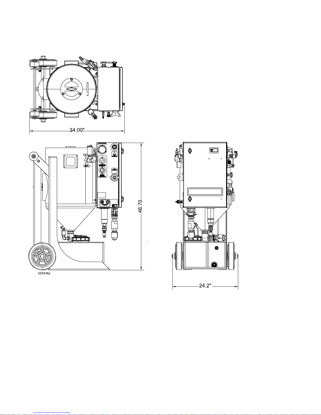
Dimensions
Dimensions Dimensions
Dimensions
48334142F
Page 49

TechnicalSpecications
Technical Technical
Technical
Specications Specications
Specications
EQ100M EQ100M
EQ100M
U.S. U.S.
U.S.
Metric Metric
Metric
MaximumWorkingPressure125psi8.6bar,0.86MPa
OperatingTemperature35°–110°F1.6°–43.3°C
RecommendedCompressor185–375cfm
5.23–10.62m^3/min
BlastHoseSize
1in.ID25.4mmID
AbrasiveCapacity
100–250lb45–114kg
DryWeight360lb164kg
WetWeight900lb400kg
PressurePotVolume
2.0cubicfeet
57liters
WaterTankVolume10gallon38liters
Air Air
Air
Supply Supply
Supply
Hose Hose
Hose
Minimum Minimum
Minimum
ID ID
ID
185–600cfmcompressorandlessthan100ft
hoselength
1.5in.ID38mmID
Over600cfmcompressororgreaterthan
100ft.hoselength
2in.ID51mmID
Sound Sound
Sound
Data* Data*
Data*
SoundPressureLevel133dB(A)133dB(A)
SoundPowerLevel139dB(A)139dB(A)
InstantaneousSoundPressureLevel131dB(C)131dB(C)
*Allreadingsweretakenatthemaximumsystemblastpressure125psi(8.6bar,0.86MPa)fromtheoperator
position.Theabrasiveusedwasgarnetandthesubstratewassteel.TestedinaccordancewithISO9614–2.
334142F49
Page 50

Graco Graco
Graco
Extended Extended
Extended
Warranty Warranty
Warranty
for for
for
EcoQuip EcoQuip
EcoQuip
™ ™
™
Components Components
Components
GracowarrantsallequipmentreferencedinthisdocumentwhichismanufacturedbyGracoandbearingthe
GracoorEcoQuipnametobefreefromdefectsinmaterialandworkmanshiponthedateofsaletotheoriginal
purchaserforuse.Gracowill,forthree(3)yearsfromthedateofsale,repairorreplaceanypartofthe
equipmentdeterminedbyGracotobedefective.Thiswarrantyappliesonlywhentheequipmentisinstalled,
operatedandmaintainedinaccordancewithGraco’swrittenrecommendations.
Thiswarrantydoesnotcover,andGracoshallnotbeliableforgeneralwearandtear,oranymalfunction,
damageorwearcausedbyfaultyinstallation,misapplication,abrasion,corrosion,inadequateorimproper
maintenance,negligence,accident,tampering,orsubstitutionofnon-Gracocomponentparts.NorshallGraco
beliableformalfunction,damageorwearcausedbytheincompatibilityofGracoequipmentwithstructures,
accessories,equipmentormaterialsnotsuppliedbyGraco,ortheimproperdesign,manufacture,installation,
operationormaintenanceofstructures,accessories,equipmentormaterialsnotsuppliedbyGraco.
Thiswarrantyisconditionedupontheprepaidreturnoftheequipmentclaimedtobedefectivetoanauthorized
Gracodistributorforvericationoftheclaimeddefect.Iftheclaimeddefectisveried,Gracowillrepairorreplace
freeofchargeanydefectiveparts.Theequipmentwillbereturnedtotheoriginalpurchasertransportation
prepaid.Ifinspectionoftheequipmentdoesnotdiscloseanydefectinmaterialorworkmanship,repairswillbe
madeatareasonablecharge,whichchargesmayincludethecostsofparts,labor,andtransportation.
THIS THIS
THIS
WARRANTY WARRANTY
WARRANTY
IS ISISEXCLUSIVE, EXCLUSIVE,
EXCLUSIVE,
AND AND
AND
IS IS
IS
IN IN
IN
LIEU LIEU
LIEU
OF OF
OF
ANY ANY
ANY
OTHER OTHER
OTHER
WARRANTIES, WARRANTIES,
WARRANTIES,
EXPRESS EXPRESS
EXPRESS
OR OR
OR
IMPLIED, IMPLIED,
IMPLIED,
INCLUDING INCLUDING
INCLUDING
BUT BUT
BUT
NOT NOT
NOT
LIMITED LIMITED
LIMITED
TO TO
TO
WARRANTY WARRANTY
WARRANTY
OF OF
OF
MERCHANTABILITY MERCHANTABILITY
MERCHANTABILITY
OR OR
OR
WARRANTY WARRANTY
WARRANTY
OF OF
OF
FITNESS FITNESS
FITNESS
FOR FOR
FOR
A AAPARTICULAR PARTICULAR
PARTICULAR
PURPOSE. PURPOSE.
PURPOSE.
Graco’ssoleobligationandbuyer’ssoleremedyforanybreachofwarrantyshallbeassetforthabove.The
buyeragreesthatnootherremedy(including,butnotlimitedto,incidentalorconsequentialdamagesforlost
prots,lostsales,injurytopersonorproperty,oranyotherincidentalorconsequentialloss)shallbeavailable.
Anyactionforbreachofwarrantyhereundermustbebroughtwithinthelatteroftwo(2)yearsofthedateofsale,
orone(1)yearafterthewarrantyperiodexpires.
GRACO GRACO
GRACO
MAKES MAKES
MAKES
NO NO
NO
WARRANTY, WARRANTY,
WARRANTY,
AND AND
AND
DISCLAIMS DISCLAIMS
DISCLAIMS
ALL ALL
ALL
IMPLIED IMPLIED
IMPLIED
WARRANTIES WARRANTIES
WARRANTIES
OF OF
OF
MERCHANTABILITY MERCHANTABILITY
MERCHANTABILITY
AND AND
AND
FITNESS FITNESS
FITNESS
FOR FOR
FOR
A AAPARTICULAR PARTICULAR
PARTICULAR
PURPOSE, PURPOSE,
PURPOSE,
IN IN
IN
CONNECTION CONNECTION
CONNECTION
WITH WITH
WITH
ACCESSORIES, ACCESSORIES,
ACCESSORIES,
EQUIPMENT, EQUIPMENT,
EQUIPMENT,
MATERIALS MATERIALS
MATERIALS
OR OR
OR
COMPONENTS COMPONENTS
COMPONENTS
SOLD SOLD
SOLD
BUT BUT
BUT
NOT NOT
NOT
MANUFACTURED MANUFACTURED
MANUFACTURED
BY BY
BY
GRACO. GRACO.
GRACO.
These These
These
items items
items
sold, sold,
sold,
but but
but
not not
not
manufactured manufactured
manufactured
by by
by
Graco Graco
Graco
(such (such
(such
as as
as
electric electric
electric
motors, motors,
motors,
switches, switches,
switches,
compressors, compressors,
compressors,
engines, engines,
engines,
trailer trailer
trailer
components, components,
components,
blast blast
blast
hose hose
hose
or ororother other
other
hose hose
hose
and and
and
blast blast
blast
nozzles), nozzles),
nozzles),
are are
are
subject subject
subject
to totothe the
the
warranty, warranty,
warranty,
if ififany, any,
any,
of ofoftheir their
their
manufacturer. manufacturer.
manufacturer.
Graco Graco
Graco
will will
will
provide provide
provide
purchaser purchaser
purchaser
with with
with
reasonable reasonable
reasonable
assistance assistance
assistance
in ininmaking making
making
any any
any
claim claim
claim
for for
for
breach breach
breach
of ofofthese these
these
warranties. warranties.
warranties.
InnoeventwillGracobeliableforindirect,incidental,specialorconsequentialdamagesresultingfromGraco
supplyingequipmenthereunder,orthefurnishing,performance,oruseofanyproductsorothergoodssold
hereto,whetherduetoabreachofcontract,breachofwarranty,thenegligenceofGraco,orotherwise.
FORGRACOCANADACUSTOMERS
ThePartiesacknowledgethattheyhaverequiredthatthepresentdocument,aswellasalldocuments,notices
andlegalproceedingsenteredinto,givenorinstitutedpursuantheretoorrelatingdirectlyorindirectlyhereto,be
drawnupinEnglish.Lespartiesreconnaissentavoirconvenuquelarédactionduprésentedocumentseraen
Anglais,ainsiquetousdocuments,avisetprocéduresjudiciairesexécutés,donnésouintentés,àlasuitedeou
enrapport,directementouindirectement,aveclesprocéduresconcernées.
Graco Graco
Graco
Information Information
Information
ForthelatestinformationaboutGracoproducts,visitwww.graco.com.
Forpatentinformation,seewww.graco.com/patents.
To To
To
place place
place
an an
an
order, order,
order,
contactyourGracoDistributororcalltoidentifythenearestdistributor.
Phone: Phone:
Phone:
612-623-6921or ororToll Toll
Toll
Free: Free:
Free:
1-800-328-0211Fax: Fax:
Fax:
612-378-3505
All written and visual data contained in this document reects the latest product information available at the time of publication.
Graco reserves the right to make changes at any
time without notice.
Original Instructions. This manual contains English. MM 334142
Graco
Graco
Graco Headquarters:
Headquarters:
Headquarters: Minneapolis
International
International
International Ofces:
Ofces:
Ofces: Belgium, China, Japan, Korea
GRACO
GRACO
GRACO INC.
INC.
INC. AND
AND
AND SUBSIDIARIES
SUBSIDIARIES
SUBSIDIARIES ••• P.O.
P.O.
P.O. BOX
BOX
BOX 1441
1441
1441 ••• MINNEAPOLIS
MINNEAPOLIS
MINNEAPOLIS MNMNMN 55440-1441
55440-1441
55440-1441 ••• USA
USA
USA
Copyright
Copyright
Copyright 2014,
2014,
2014, Graco
Graco
Graco Inc.
Inc.
Inc. All
All
All Graco
Graco
Graco manufacturing
manufacturing
manufacturing locations
locations
locations are
are
are registered
registered
registered tototo ISO
ISO
ISO 9001.
9001.
9001.
www.graco.com
Revision F, May 2016
 Loading...