

Page 1
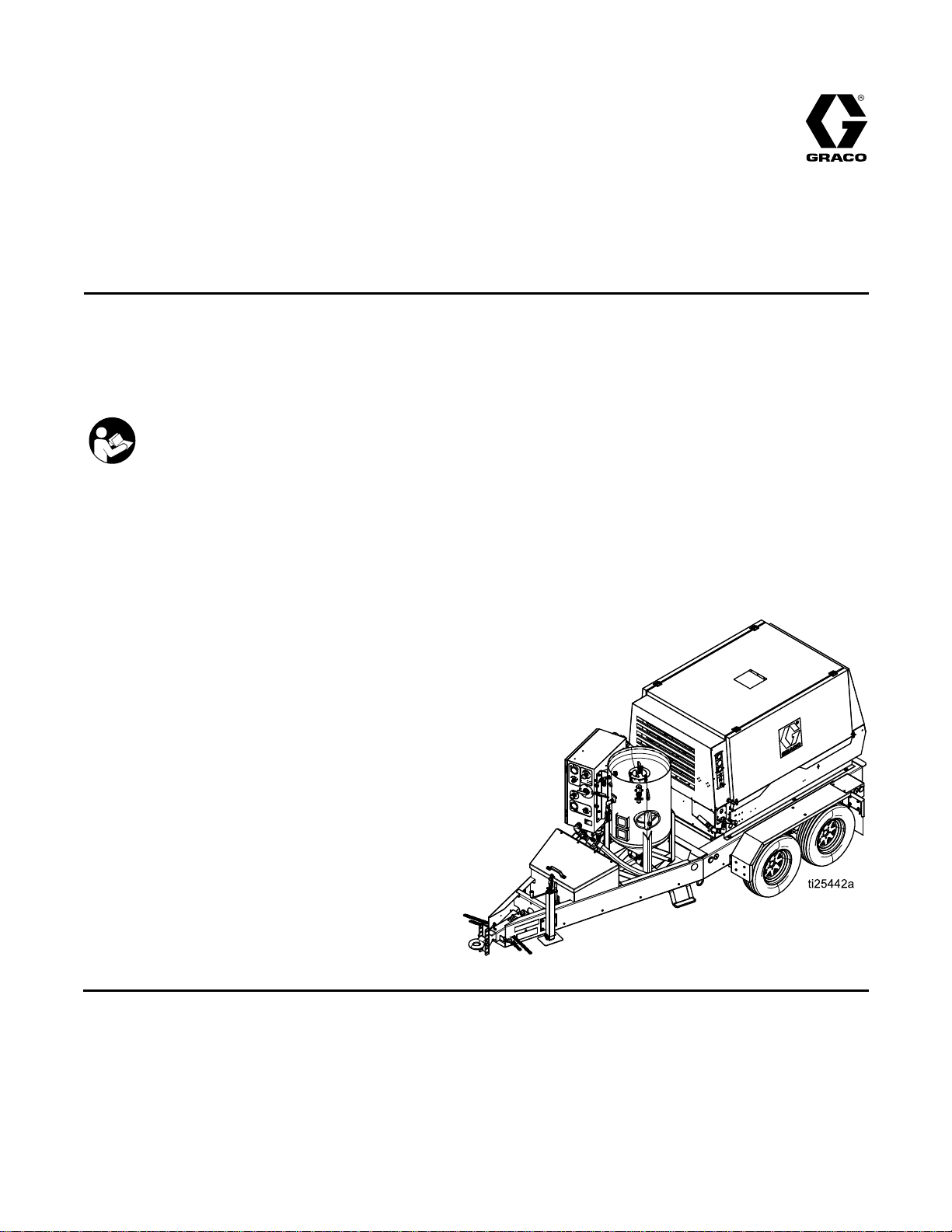
Operation,Repair,andParts
EcoQuip
EcoQuip EcoQuip
Blast
Blast Blast
Vapor
Vapor Vapor
or
or or
125
125 125
Working
Working Working
See
See See
abrasive
abrasive abrasive
hazardous
hazardous hazardous
Important
Important Important
Readallwarningsandinstructionsinthismanual.Savethese
instructions.
psi
psi psi
page
page page
System
System System
blast
blast blast
locations.
locations. locations.
Safety
Safety Safety
(8.6
bar,
(8.6 (8.6
bar, bar,
Pressure
Pressure Pressure
for
Model
2 22for for
Model Model
Vapor
Vapor Vapor
Abrasive
Abrasive Abrasive
334666C
EN
system.
system. system.
Instructions
Instructions Instructions
0.86
0.86 0.86
For
professional
For For
professional professional
MPa)
MPa) MPa)
Maximum
Maximum Maximum
information.
information. information.
use
only.
Not
use use
only. only.
approved
Not Not
approved approved
for
use
for for
use use
explosive
in ininexplosive explosive
atmospheres
atmospheres atmospheres
PROVENQUALITY.LEADINGTECHNOLOGY.
Page 2

Contents
Contents Contents
Models...............................................................2
RelatedManuals................................................2
Warnings...........................................................3
Notes.................................................................5
SystemComponentIdentication.........................6
EQ200TandEQ400T...................................6
DataTrakControls........................................7
PressureReliefProcedure..................................8
Operation...........................................................9
ChecklistBeforeStarting..............................9
LiftingtheTrailerSystems............................9
ConnectingtheBlastHoseandAir
Hose..............................................10
SettingUptheEquipment.............................11
BlastingTips................................................15
UsingtheWashFeature...............................17
RellingthePotwithAbrasive.......................18
ShuttingDown.............................................19
WinterizingtheEquipment............................21
Troubleshooting..................................................22
TroubleshootingExamples...........................25
Repair................................................................27
RepairingtheMainAirRegulator..................27
FlushingtheDiaphragmValve......................28
RepairingtheDiaphragmValve.....................29
CleaningtheAuto-VentValve.......................30
ReplacingtheDataTrakBattery....................31
ReplacingtheDataTrakFuse.......................32
Notes.................................................................33
Parts..................................................................34
EQ200TandEQ400T...................................34
Enclosure....................................................36
Trailers........................................................38
PressurePot................................................41
HoseSchematic.................................................42
VaporAbrasiveBlastSystemsand
Accessories..........................................43
EcoQuipSystemCongurator.......................43
ModelSeries...............................................44
Hoses.........................................................45
BlastControlHoses/Cables..........................46
Nozzles.......................................................46
CommonSpareParts...................................47
OtherAccessories........................................47
Dimensions........................................................48
TechnicalSpecications......................................50
GracoExtendedWarrantyforEcoQuip™
Components.........................................52
Models
Models Models
Model
Model Model
EQ200TEcoQuip200VaporBlastSystem
EQ400TEcoQuip400VaporBlastSystem
Description
Description Description
Related
Related Related
Manual
Manual Manual
313840DataTrak
333397Pump
334142
334143
334667
Manuals
Manuals Manuals
Number
Number Number
Product
Product Product
EQ100M
EQ300S,EQ600S
EQ300C,EQ600C
2
334666C
Page 3
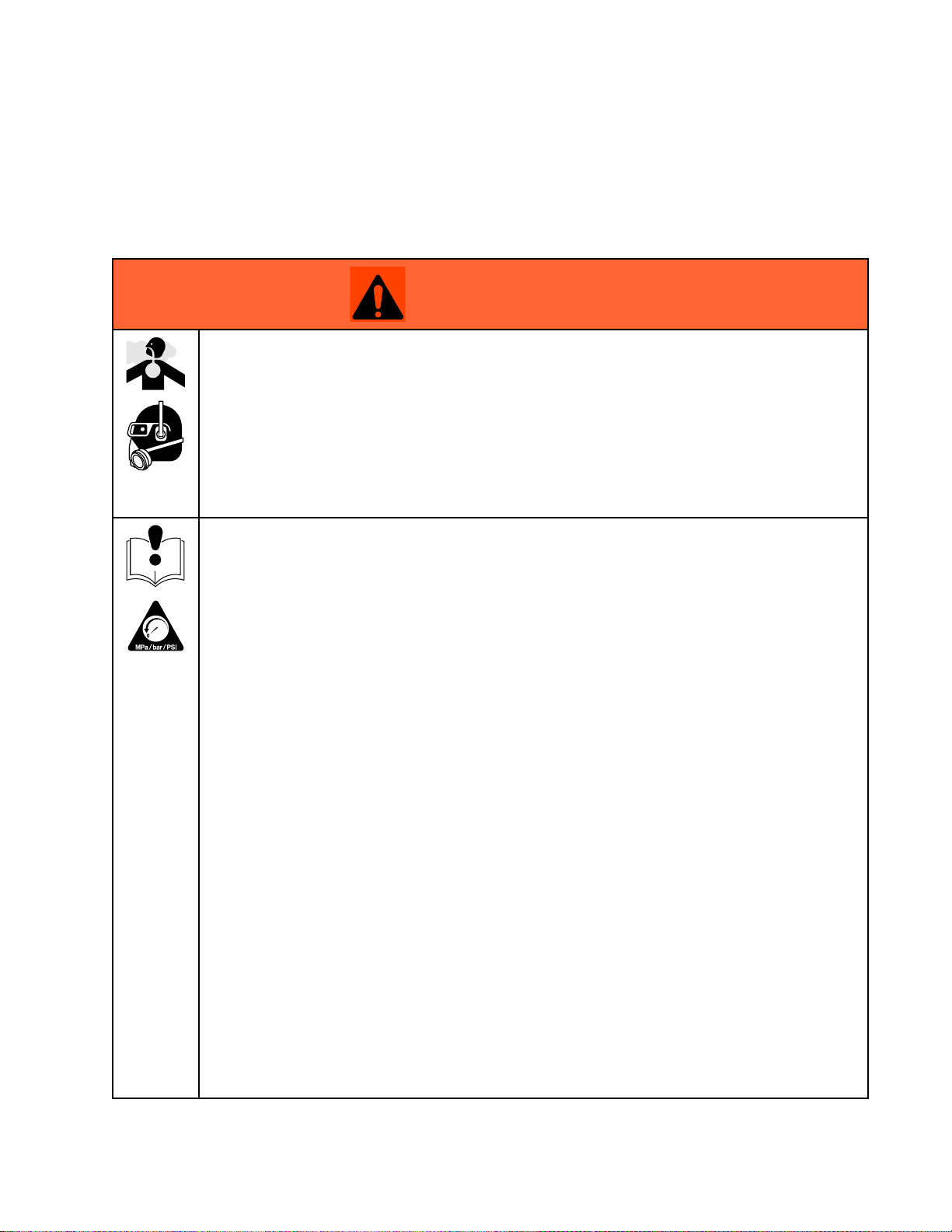
Warnings
Warnings Warnings
Thefollowingwarningsareforthesetup,use,grounding,maintenance,andrepairofthisequipment.The
exclamationpointsymbolalertsyoutoageneralwarningandthehazardsymbolsrefertoprocedure-specic
risks.Whenthesesymbolsappearinthebodyofthismanualoronwarninglabels,referbacktothese
Warnings.Product-specichazardsymbolsandwarningsnotcoveredinthissectionmayappearthroughout
thebodyofthismanualwhereapplicable.
WARNING
WARNING WARNING
DUST
DUST DUST
Useofthisequipmentcanresultinthereleaseofpotentiallyharmfuldustortoxicsubstances
fromtheabrasivebeingused,thecoatingsbeingremoved,andthebaseobjectbeingblasted.
•Foruseonlybysophisticatedusersfamiliarwithapplicablegovernmentalsafetyandindustrial
•Useequipmentonlyinawell-ventilatedarea.
•Wearaproperlyt-testedandgovernmentapprovedrespiratorsuitableforthedustconditions.
•Followlocalordinancesand/orregulationsfordisposaloftoxicsubstancesanddebris.
EQUIPMENT
EQUIPMENT EQUIPMENT
AND
DEBRIS
AND AND
DEBRIS DEBRIS
hygieneregulators.
MISUSE
MISUSE MISUSE
HAZARD
HAZARD HAZARD
HAZARD
HAZARD HAZARD
Warnings
Misusecancausedeathorseriousinjury.
•Donotoperatetheunitwhenfatiguedorundertheinuenceofdrugsoralcohol.
•Donotexceedthemaximumworkingpressureortemperatureratingofthelowestrated
systemcomponent.SeeTechnical Technical
•Donotusethisequipmentwithouthoserestraintsandcouplerpinsinstalledonallairand
blasthosecouplings.
•Donotblastunstableobjects.Thehighamountofuidowfromthenozzlecanpotentially
moveheavyobjects.
•Donotexceedloadratingoflifteyes.
•Donotoperateequipmentonorstandonanunstablesupport.Keepeffectivefootingand
balanceatalltimes.
•Useuidsandsolventsthatarecompatiblewithequipmentwettedparts.SeeTechnicalData
inallequipmentmanuals.Readuidandsolventmanufacturer’swarnings.Forcomplete
informationaboutyourmaterial,requestMSDSfromdistributororretailer.
•Donotleavetheworkareawhileequipmentisenergizedorunderpressure.
•TurnoffallequipmentandfollowthePressure Pressure
•Checkequipmentdaily.Repairorreplacewornordamagedpartsimmediatelywithgenuine
manufacturer’sreplacementpartsonly.
•Donotalterormodifyequipment.Alterationsormodicationsmayvoidagencyapprovals
andcreatesafetyhazards.
•Makesureallequipmentisratedandapprovedfortheenvironmentinwhichyouareusingit.
•Useequipmentonlyforitsintendedpurpose.Callyourdistributorforinformation.
•Routehosesandcablesawayfromtrafcareas,sharpedges,movingparts,andhotsurfaces.
•Donotkinkoroverbendhosesorusehosestopullequipment.
•Keepchildrenandanimalsawayfromworkarea.
•Complywithallapplicablesafetyregulations.
Technical
Data
Data Data
Pressure
inallequipmentmanuals.
Relief
Relief Relief
Procedure
Procedure Procedure
whenequipmentisnotinuse.
334666C 3
Page 4
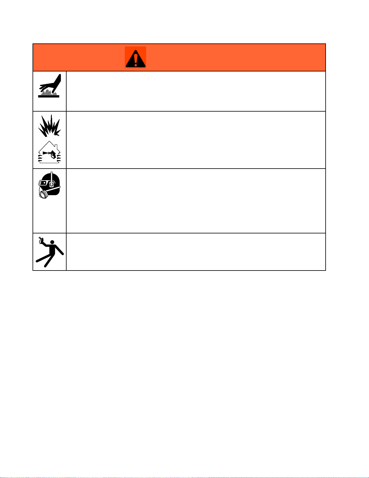
Warnings
WARNING
WARNING WARNING
BURN
BURN BURN
Equipmentsurfacesanduidthatisheatedcanbecomeveryhotduringoperation.Toavoid
severeburns:
•Donottouchhotuidorequipment.
FIRE
FIRE FIRE
Flammablefumes,suchassolvent,inwork work
andexplosion:
•Useequipmentonlyinwellventilatedarea.
•Keepworkareafreeofdebris,includingsolvent,ragsandgasoline.
•Keepaworkingreextinguisherintheworkarea.
PERSONAL
PERSONAL PERSONAL
Wearappropriateprotectiveequipmentwhenintheworkareatohelppreventseriousinjury,
includingeyeinjury,hearingloss,inhalationoftoxicfumes,andburns.Protectiveequipment
includesbutisnotlimitedto:
HAZARD
HAZARD HAZARD
AND
EXPLOSION
AND AND
EXPLOSION EXPLOSION
PROTECTIVE
PROTECTIVE PROTECTIVE
HAZARD
HAZARD HAZARD
work
area
area area
canigniteorexplode.Tohelppreventre
EQUIPMENT
EQUIPMENT EQUIPMENT
•Protectiveeyewearandhearingprotection
•Protectiveclothing,shoesandgloves
•Properlyt-testedandgovernmentapprovedrespiratorsuitableforthedustconditions
RECOIL
RECOIL RECOIL
Blastnozzlemayrecoilwhentriggered.Ifyouarenotstandingsecurely,youcouldfalland
beseriouslyinjured.
HAZARD
HAZARD HAZARD
4
334666C
Page 5

Notes
Notes
Notes Notes
334666C 5
Page 6
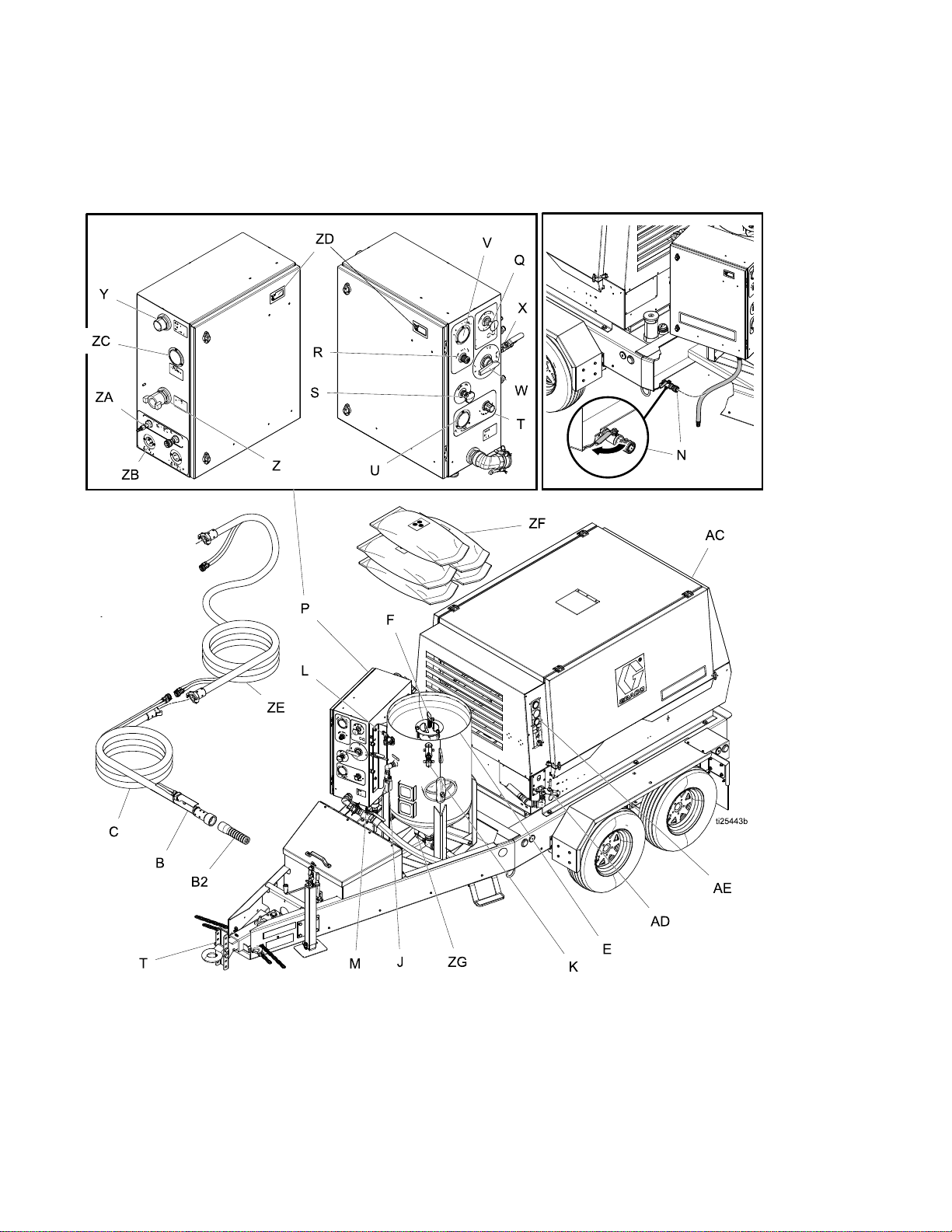
SystemComponentIdentication
System
System System
EQ200T
EQ200T EQ200T
Component
Component Component
and
EQ400T
and and
EQ400T EQ400T
Identication
Identication Identication
6 334666C
Page 7
SystemComponentIdentication
8800000
83000
9
Key:
Key: Key:
B
B2BlastNozzle
C
EPot
FPop-UpPin
JPotDumpValve
KAutoVentValve
L
MAbrasiveBallValve
NInletBallValve
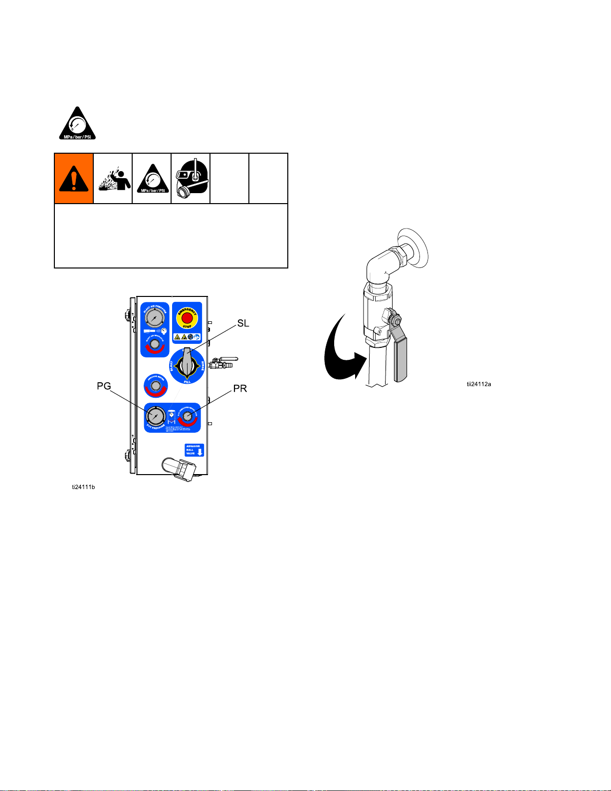
P
QEmergencyStop
RBlastAirRegulator
S
TPotPressureRegulator
U
DataTrak
DataTrak DataTrak
BlastControlSwitch
BlastHose
BlastCheckValve
ControlBox
AbrasiveMeteringValve
PotPressureGauge
Key:
Key: Key:
V
W
XRinseBallValve
Y
Z
ZA
ZB
ZCSupplyAirPressureGauge
ZD
ZEAccessoryExtensionhose
ZFAbrasiveMaterial
ZGFillPortCheckValve
ACAirCompressor
AD
AE
Controls
Controls Controls
BlastAirPressureGauge
SelectorValve
AirSupplyConnection
BlastConnection
PneumaticControlConnection
ElectricControlConnection
DataTrak(seeDataTrakControls,page7)
AirConnections
AirCompressorControls
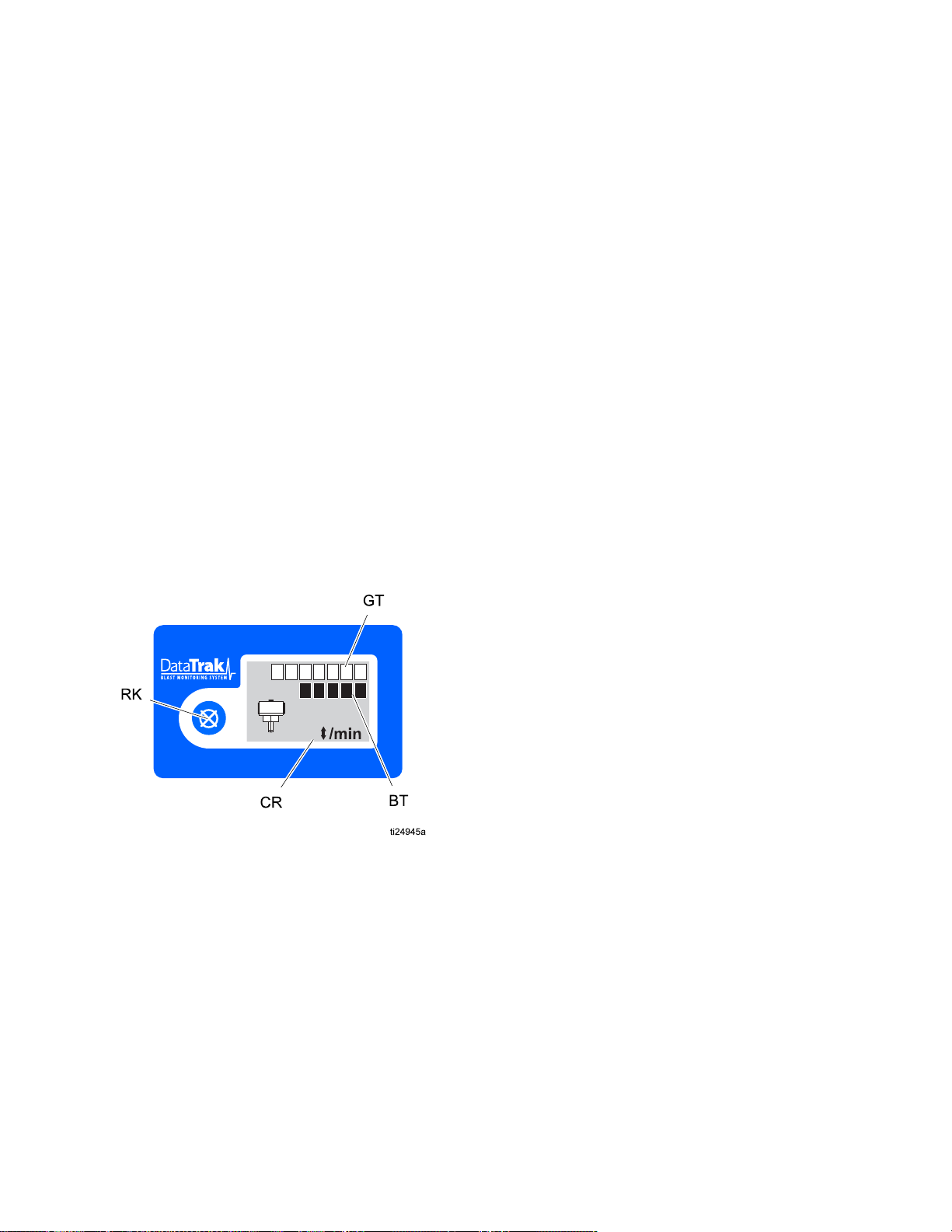
Key:
Key: Key:
RK
CRCycle/Rate
BTBatchTotalizer
GTGrandTotalizer
334666C
ResetKey—Resultsinfaults.Pressand
holdforthreesecondstoclearthebatch
totalizer.
7
Page 8
PressureReliefProcedure
Pressure
Pressure Pressure
Thisequipmentstayspressurizeduntilpressure
ismanuallyrelieved.Tohelppreventserious
injuryfrompressurizeduid,suchassplashing
uid,followthePressureReliefProcedurewhen
instructed.
1.Turnthepotpressureregulator(PR)off.
Relief
Relief Relief
FollowthePressureReliefProcedure
wheneveryouseethissymbol.
Procedure
Procedure Procedure
2.Closetheabrasiveballvalve.
3.Turnthecompressoroff.Closethecompressor
supplyairvalve.
4.Engagetheblastcontrolswitchtorelieve
pressureinthesystem.
5.Verifythatthesupplyairpressuregaugereads0
psi.Thendisconnecttheairinlethosefromthe
system.
6.Turntheselectorvalve(SL)toFILL.
7.Openthedumpvalve.
8.Verifythatthepotpressuregauge(PG)displays
zeropressure.
8 334666C
Page 9

Operation
Operation
Operation Operation
Checklist
Checklist Checklist
•Checkthecompressedairsupplyaccordingtoits
operatormanual.Makesuretheairbeingsupplied
iscleanandrelativelyfreeofmoistureandoil
topreventwatercontaminationoftheaircontrol
components.
•Makesureairdeliveryvalvesareclosedbeforethe
airsupplycompressorisstarted.
•Makesureallrequiredhoserestraintsandcoupler
pinsareinworkingconditionandproperlyinstalled.
•Makesuretheequipmentissituatedonlevel
ground.Failuretokeeptheunitonlevelground
willmakeitdifcultorimpossibletopurgeallofthe
airfromthepressurevessel.
•Makesuretheequipmentisproperlysupportedon
asurfacethatcanholditstotalweight.Theweight
ofallpersonnel,thematerialbeingblasted,and
anyabrasivebeingstoredmustalsobeconsidered
(seeTechnicalSpecications,page50).
•Makesurethewatertankwillremainfullysupplied
withcleanwatertoavoidanypossibilityofthe
pumprunningdryduringblasting.
•Makesurethatthepotiscleanandfreeofany
internaldebris.
Before
Before Before
Starting
Starting Starting
beusedwithhoselengthslessthan150ft(45m).
Blastingwith150ft(45m)ormoreofblasthose
requirestheuseofanelectricblastcontrolswitch.
•Makesuretheblasthoseislaidoutasstraightas
possiblebetweentheequipmentandtheworksite
(acoiledblasthosewilluncoilunderpressure).
NOTICE
NOTICE NOTICE
Sharpbendsintheblasthosecouldcausethe
abrasivetowearthroughthehoseandcause
prematurefailureofthehose.
•Makesuretherubbergasketineachhosecoupler
isinworkingcondition.
Lifting
Lifting Lifting
•Liftthesystemwithaliftapparatusrated
appropriatelyfortheweightofthesystem(see
TechnicalSpecications,page50).
•Donotliftthesystembytheliftringontopofthe
compressor.
•Donotliftthesystembythetie-downringsonthe
trailer.
•Donotliftthesystembytheliftringsonthepot.
the
Trailer
the the
Trailer Trailer
Systems
Systems Systems
•Makesuretousethecorrecttypeofblastcontrol.
Anelectricorpneumaticblastcontrolswitchcan
334666C 9
Page 10
Operation
OFF
START
RUN
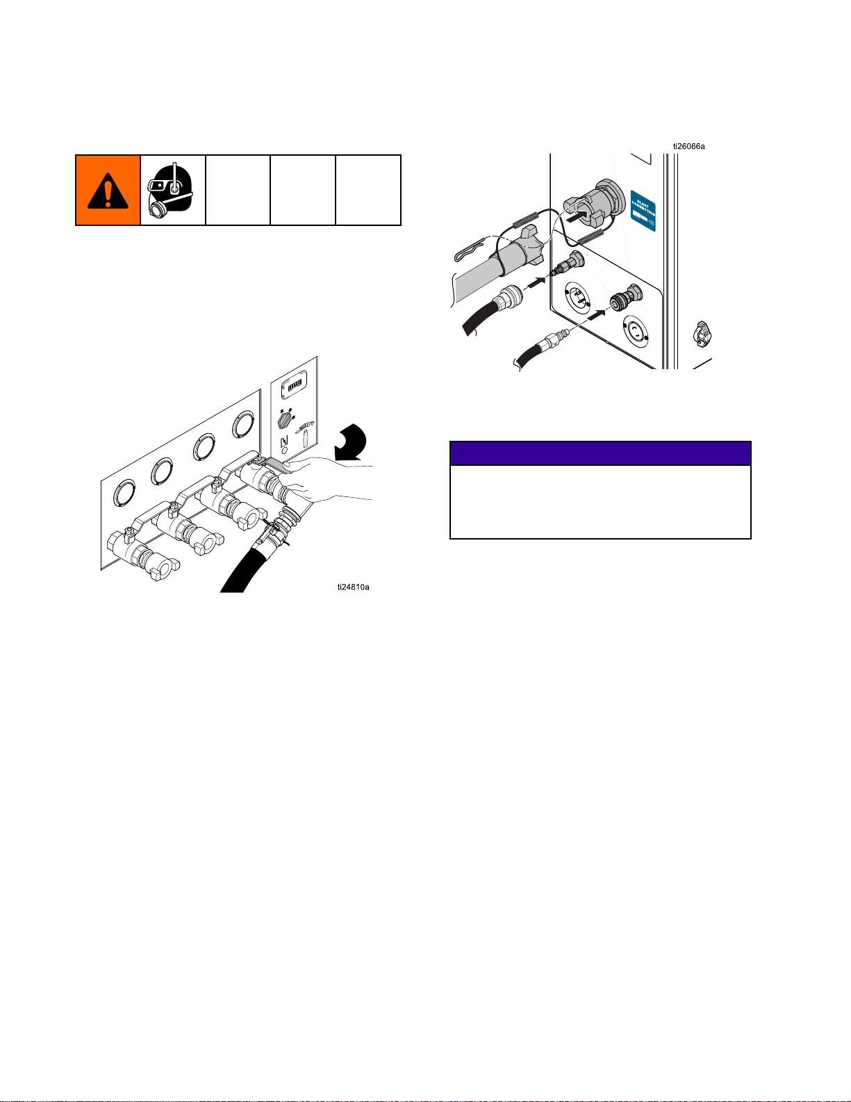
Connecting
Connecting Connecting
Hose
Hose Hose
1.Makesuretheinlethoseconnectionsaretight,
andthathoserestraintsareproperlyinstalled
andsecure.
2.Opentheairsupplyvalve(125psi,8.6Bar,0.86
MPamaximum).Ifnecessary,usearegulatorin
thesupplyairlinetomeetthesespecications.
the
Blast
the the
Blast Blast
Hose
Hose Hose
and
and and
Air
Air Air
3.Connecttheblasthose,hoserestraints,control
hoses,andcouplerpins.
NOTE:
NOTE: NOTE:
switch,checkalloftheelectricalconnections
fromthepaneltotheblastcontrol.
Ifyouareusinganelectricblastcontrol
NOTICE
NOTICE NOTICE
Makesurenoelectricalconnectionswill
beexposedtowater.Exposuretowater
couldcauseashortcircuitanddamagethe
equipment.
NOTE:
NOTE: NOTE:
andstartupinformation.
Seeaircompressormanualforoperation
10 334666C
Page 11
Operation
Setting
Setting Setting
1.Disconnecttheabrasivehoseatthecamand
groovewiththeabrasiveballvalveclosed.
NOTE:
NOTE: NOTE:
(especiallyunderpressure),releasingthecam
andgroovewiththeballvalveopenwillcausean
unintentionalreleaseofabrasive.
Up
the
Up Up
Ifthepotcontainswaterandabrasive
Equipment
the the
Equipment Equipment
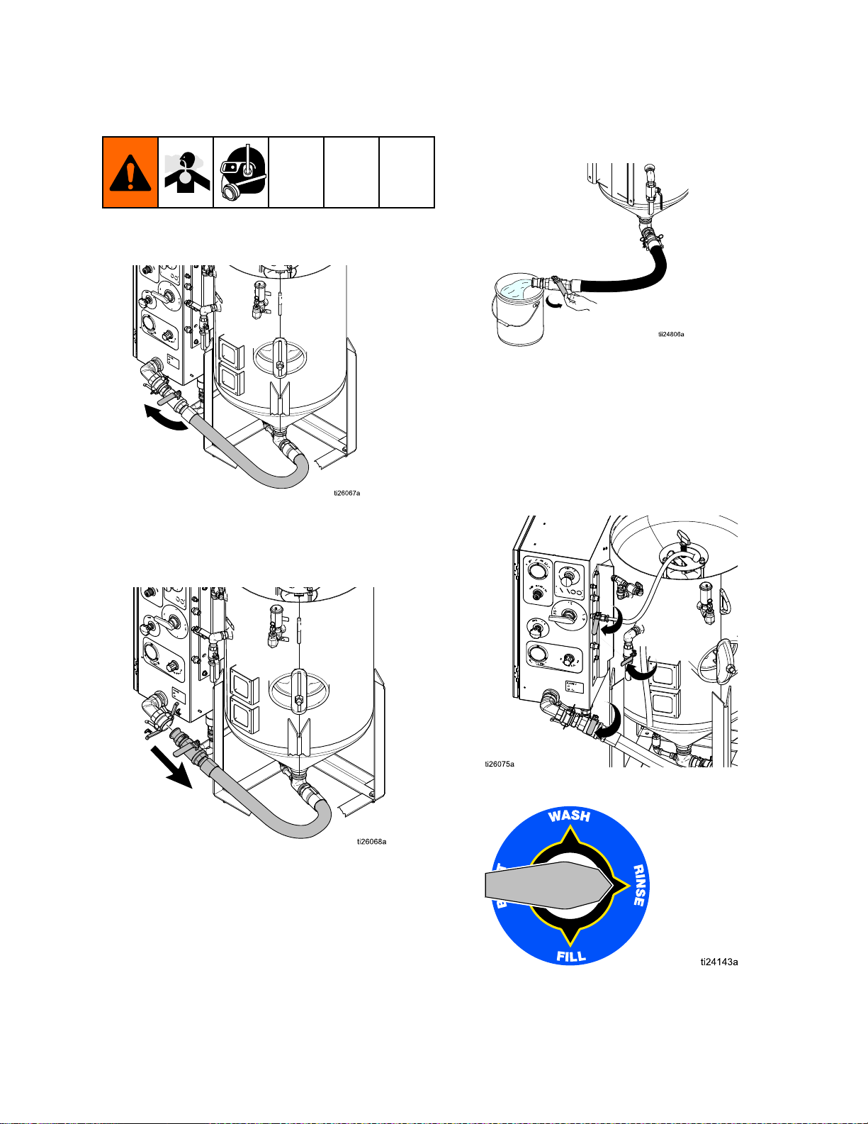
2.Flushwaterthroughthepotandoutofthe
disconnectedabrasiveballvalvebeforellingthe
potwithwaterandabrasive.
3.Reconnecttheabrasivehose.
4.Disconnectthepumpinlethoseandushthe
watertanktoremoveanyremainingdebris.
Reconnectthepumpinlethose.
5.Fillthewatertankonlywithfreshwater,then
opentheinletballvalve.
6.Closetherinse,dump,andabrasiveballvalves.
7.TurntheselectorvalvetoRINSE.
334666C
11
Page 12
Operation
1
2
10 gal
(30 L)
200-500 lb
(90-227 kg)
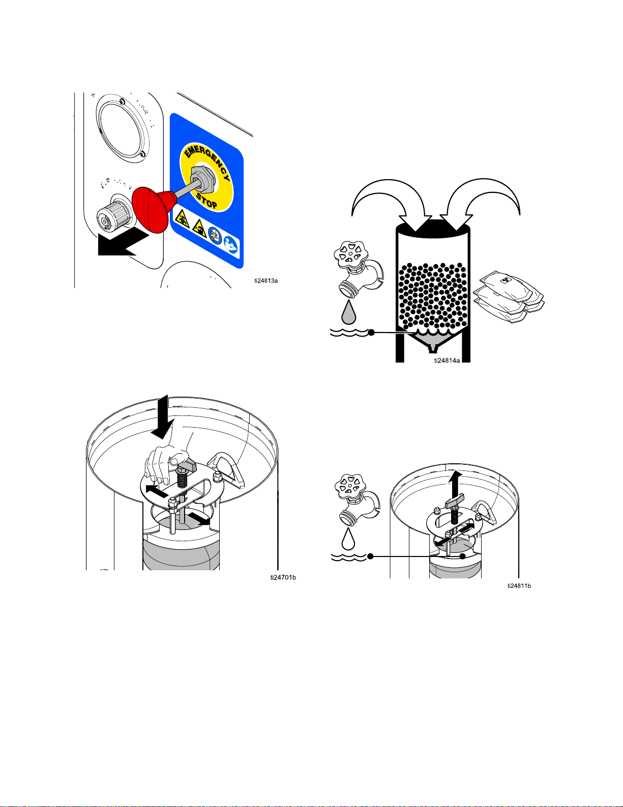
8.DisengagetheEmergencyStop.
NOTE:
NOTE: NOTE:
EmergencyStopisdisengaged.
9.Alignthepop-uphandlewiththepinslot,and
thenrmlypushandturnthehandle90°afterthe
pinisbelowthebracketslot.Properengagement
ofthepinwillholdthepop-updownuntilitis
released.
Thewaterpumpwillnotworkunlessthe
10.Add10gallons(30liters)offreshwaterto
thepot.Wearappropriatepersonalprotective
equipment,includinganappropriatelyt-tested
governmentapprovedrespiratorsuitableforthe
dustconditions.Addabrasivematerial(minimum
fourbags,maximumten50lb(23kg)bagsof
high-massabrasive,oreight50lb(23kg)bags
oflowmassabrasive).
11.Useagardenhoseortherinsehosetowashthe
abrasiveintothepotandclearanyabrasivefrom
thepop-upandgasket.
12.Whenthewaterlevelreachesthepop-upgasket,
rotatethehandletoreleasethepop-uppin.
NOTE:
NOTE: NOTE:
alldebris.
Makesurethepop-upgasketiscleanof
12
334666C
Page 13
Operation
ti24824a
13.TurntheselectorvalvetoFILL.
NOTE:
NOTE: NOTE:
Thewaterpumpshouldbegincycling.If
not,openthepotpressureregulatorenoughto
causethepumptorunat60cpm.
NOTE:
NOTE: NOTE:
Theautovent/purgevalvewillallowall
oftheairtrappedinthetopofthepottovent.
Whenairstopsventing,thepotpressuregauge
willstarttoregisterpressure.
14.Waitforpotpressuretoincrease.NOTE: NOTE:
cantakeuptoseveralminutesforthepotto
pressurize.
NOTE:
NOTE: NOTE:
Thepop-upcannotbepusheddown
unlessallofthepressureinthepotisreleased
byopeningthedumpvalve.
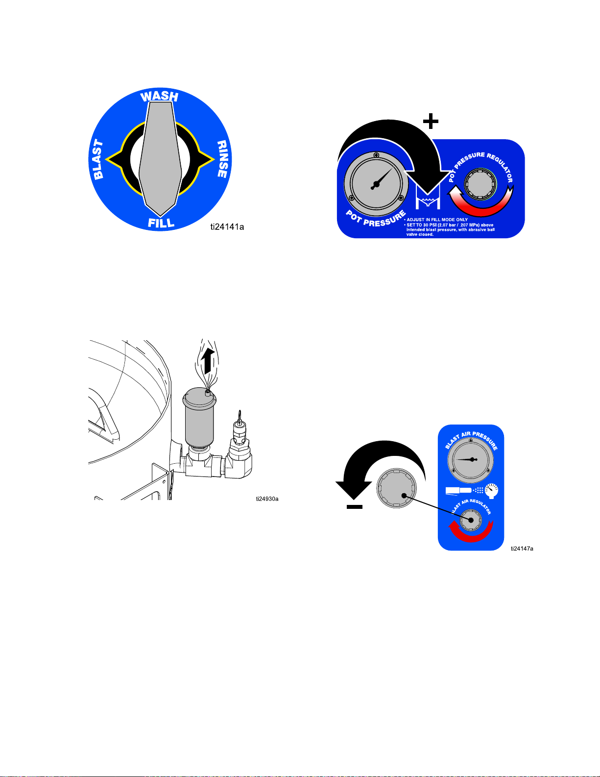
15.Setthepotpressure30psi(2.0Bar,0.2MPa)
higherthantheintendedblastpressure.Open
andclosethedumpvalveafterthepumpstalls.
Relievepotpressureto40psi(2.7Bar,0.27
MPa)beforeclosingthedumpvalve.Repeat
untilpotpressureisconsistent.
NOTE:
It
16.TurntheselectorvalvetoWASH.
17.Settheblastairpressure30psi(2.0Bar,0.2
MPa)lowerthanthepotpressurewhileblasting.
NOTE:
NOTE: NOTE:
Inordertoadjusttheblastpressure,
theblastcontrolswitchmustbeengaged.For
theinitialsetting,leavetheabrasiveballvalve
closed.
NOTE:
NOTE: NOTE:
Engageandreleasetheblastcontrol
switcheachtimetheblastregulatorisadjusted.
18.TurntheselectorvalvetoBLAST.
334666C 13
Page 14
Operation
8800000
83000
9
19.Opentheabrasiveballvalve.
NOTE:
NOTE: NOTE:
initialsetting(itwillnotreturntotheinitialsetting
iftheabrasivemeteringvalveisclosed).
20.Engagetheblastcontrolswitchandbegin
blasting.
Makesurethepotpressurereturnstothe
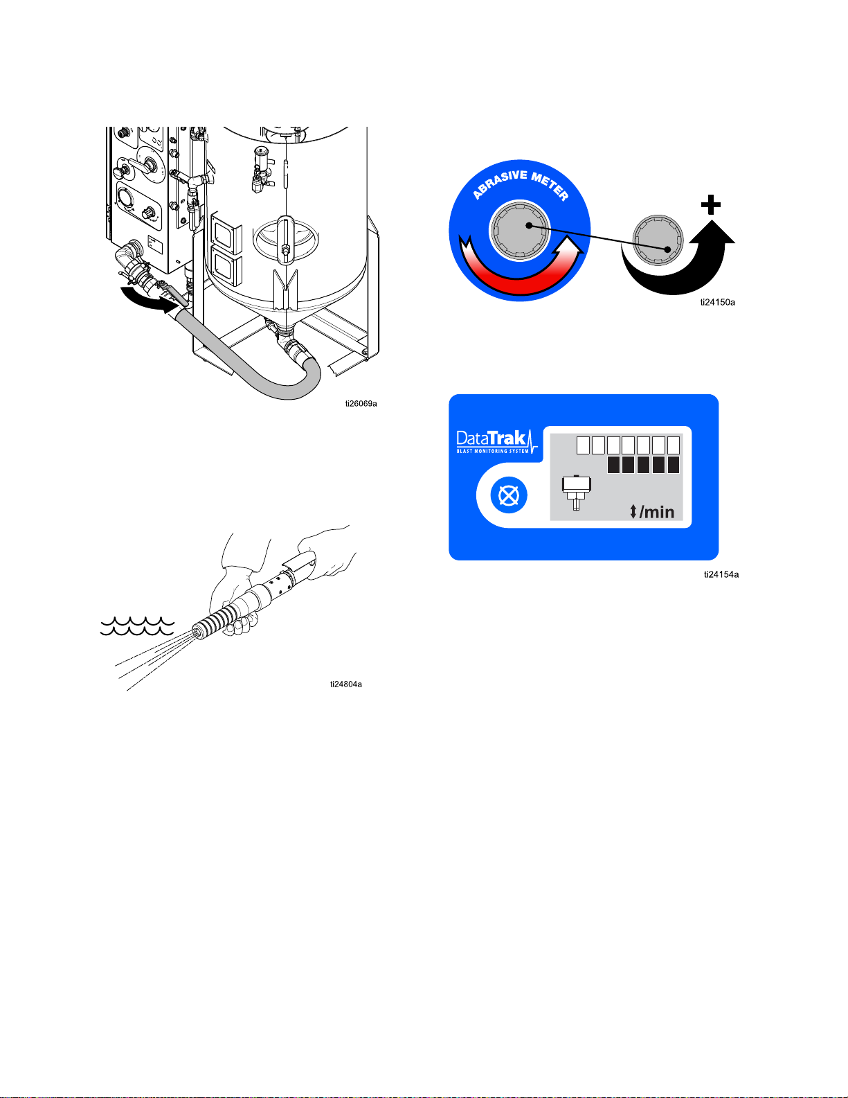
21.Slowlyadjusttheabrasivemeteringvalvewhile
theabrasiveisblastingfromthenozzle.Typical
adjustmentrangesfrom1/8to1/4turnopen.
NOTE:
NOTE: NOTE:
settingthepumpcyclerate.Optimalabrasive
mediaconsumptiontypicallyoccurswiththe
cycleratesetat7–10cyclesperminute.
TheDataTrakcanbeusedtoassistin
NOTE:
NOTE: NOTE:
abrasivematerialtoreachthenozzle.
NOTE:
NOTE: NOTE:
equalizeduringblasting.Onlysetpotpressure
withtheabrasiveballvalveclosed.Neveradjust
potpressurewhileblasting.
Youmayhavetowait1–2minutesforthe
Potpressureandblastpressureshould
NOTE:
NOTE: NOTE:
whatyouwillbeblasting.
NOTE:
NOTE: NOTE:
thenincreasetheblastforceasnecessaryto
cleanwithoutdoinganydamagetothesubstrate.
Whenproperlyset,thepumpshouldcycle7-10
timesperminute.Highproductionrateusers
mayneedtoincreasecyclerateabove10cycles
perminute.
NOTE:
NOTE: NOTE:
youstopblastingformorethan20-30minutes.
Thiswillhelptoextendtheservicelifeofthe
diaphragmvalve.
Useapieceoftestmaterialsimilarto
Alwaysstartasgentlyaspossibleand
Closetheabrasiveballvalvewhenever
14
334666C
Page 15
Operation
Blasting
Blasting Blasting
Whenrstlearningtheeffectsoftheblaster,geta
betterunderstandingoftheresultsbystartingata
shallowangle(closerto0°thanto90°)andkeep
thenozzleapproximately16in.(40cm)fromthe
application.Observetheresults,thenreducethe
distance,steepentheangle,andadjusttheblast
regulator.
Astheblastpressureisincreased,slowlyadjustthe
abrasivemeteringvalveandwatchtheDataTrak
toachieve7-10pumpcyclesperminute.See
DataTrakControls,page7.
NOTE:
NOTE: NOTE:
(i.e.80-grit),themoreaggressivetheresults.
Tips
Tips Tips
Theheavierandsmallertheabrasiveparticle
Blasting
Blasting Blasting
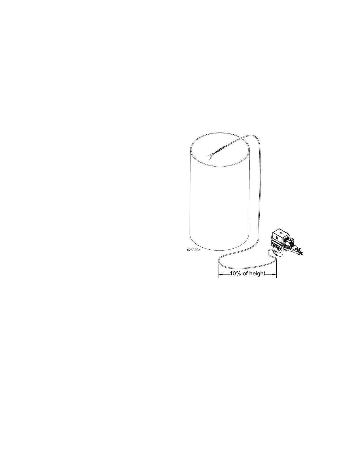
Whenblastingonasurfacehigherthanthe
equipment,makesurethatthereisalengthofblast
hoseonthegroundequalto10-20%oftheheight.
Thehoseonthegroundpreventsunspentabrasive
inthehosefromback-llingtheinternalplumbingof
thepanel.
Forexample:Whenblasting50feet(15m)straight
up,useatleast10feet(3m)ofblasthoseonthe
groundbeforetheblasthosegoesuptotheblasting
height.
on
Higher
on on
Higher Higher
Surfaces
Surfaces Surfaces
334666C 15
Page 16

Operation
Abrasive
Abrasive Abrasive
Thereisnoxedformulaforwhatworksbestineachapplication.Theinformationbelowworksbestforthe
majorityofthetime.Fromthisinitialsetting,adjustmentscanbemadeupordowntogetthefastestremoval
rateswithoutdamagetothesurface.
Normalsettingsare:110psi(7.5Bar,0.75MPa)initialpotsetting,lessthan1/2turnopenmeteringvalve,
blastingpressureat80psi(5.5Bar,0.55MPa).Forapplicationsrequiringhigherperformance,use
high-performanceabrasive(theheaviestmass@80grit)suchasGarnet,andthehighestpressuresthe
systemcansupport.Theinitialpotpressureshouldalwaysbe30psi(2.0Bar,0.2MPa)abovetheintended
blastpressure.
Graduallymakeadjustmentstomeetthespecicrequirementsforeachapplication.Makeadjustments(see
DataTrakControls,page7)toachieve7-10cyclesperminutetobethemostefcient(cutatthefastestrate
whileusingtheleastamountofabrasive).Blastingpressurescanrangebetween30-120psimax(2.0Bar,
0.2MPa–8.2Bar,0.82MPa).
Unlikeconventionalsandblasting,higherpressuresdonotnecessarilymeanbettercleaning.Nozzledistance
andtheangletothesurfacehasaneffectonperformance,asdoestheblastpressure.Choiceofabrasive
alsohasagreateffect.High-performanceabrasiveproducesthebestperformanceandcansaveenough
timetomakeupthedifferenceincost.
NOTE:
NOTE: NOTE:
General
General General
Wood
Wood Wood
Steel
Steel Steel
Fiberglass
Fiberglass Fiberglass
Metering
Metering Metering
Blastingwith150ft(45m)ormoreblasthoserequirestheuseofanelectricblastcontrol.
40/70crushed
glass
80(usingalow
massabrasive
likecrushedglass
orwalnut)
60–80(using
ahigh-mass
abrasivelike
Garnet)
40-70lowmass
Valve
Valve Valve
Grit
Size
Grit Grit
Size Size
Settings
Settings Settings
60-80psi(4.1Bar,
0.41MPa-5.5Bar,
0.55MPa)
40-50psi(2.7Bar,
0.27MPa-3.4Bar,
0.34MPa)
100-120psi(6.8Bar,
0.68MPa-8.2Bar,
0.82MPa)
45-65psi(3.1Bar,
0.31MPa-4.4Bar,
0.44MPa)
35°-65°
15°-30°
45°-65˚
35°-45˚
Blast
Blast Blast
Blast
Blast Blast
Pressure
Pressure Pressure
Abrasive
Abrasive Abrasive
Metering
Metering Metering
10cyclesper
minute
8cyclesper
minute
10–12cyclesper
minute
8cyclesper
minute
Valve
Valve Valve
Angle
Angle Angle
None
Donotwash,asit
mayraisethewood
grain.Brushoff
excessabrasiveafter
thewooddries.
None
None
Notes
Notes Notes
NOTE:
NOTE: NOTE:
Adjustmentinblastpressurerequiresanadjustmentoftheabrasivemeteringvalve.
16 334666C
Page 17

Operation
Using
Using Using
Thewashfeaturecausesair-drivenwater(without
abrasive)torinseareasthathavealreadybeen
blastedwithabrasive.Itisalsoaconvenientfeature
forushingabrasivefromtheblasthose.
Therewillalwaysbesomeresidualabrasivein
theblasthose.Neverusethewashfeatureon
anysurfaceotherthanwhereyouhaveblasted,or
intendtoblast.Itwillaffect/dullthesurface.
Donotusethewashfeatureonwoodthathas
beenblasted.Itcoulddamagethewoodandcause
thegraintorise.Waitforthewoodtodryandthen
useabroom,brush,orvacuumtoremoveany
residualabrasive.
1.Closetheabrasiveballvalve.
the
Wash
the the
Wash Wash
Feature
Feature Feature
NOTICE
NOTICE NOTICE
NOTICE
NOTICE NOTICE
2.TurntheselectorvalvetoWASH.
3.Blast1–2minutesuntiltheabrasiveiscleared
fromthehose.
4.Theequipmentisnowreadytowashany
previouslyblastedsurfaces.
334666C
17
Page 18

Operation
Relling
Relling Relling
1.Closetheabrasiveballvalve.
2.TurntheselectorvalvetoRINSE.
3.Openthedumpvalveslowlytorelievethewater
pressureinthepot.
the
Pot
with
the the
Pot Pot
Abrasive
with with
Abrasive Abrasive
4.Afterallofthepressureinthepothasbeen
relieved,engagethepop-uppinbycompressing
thespringandturningthehandle90°toholdthe
pop-upintheopenposition.
5.Addtheabrasive(minimumfourbags,maximum
ten50lb(23kg)bagsofhigh-massabrasive
oreight50lb(23kg)bagsoflow-mass
abrasive)andcontinuetheproceduresfrom
SettingUptheEquipment,page11.
NOTE:
NOTE: NOTE:
willbedrainedfromthepot.Alldisposalsmust
complywithnational,state,andlocalregulations.
Bepreparedtocapturethewaterthat
NOTE:
NOTE: NOTE:
thepottoallowadditionalabrasivetobeadded.
Morewatermayneedtobedrainedfrom
18 334666C
Page 19

Operation
Shutting
Shutting Shutting
1.Whenyouhavenishedblasting,performwash
untilalloftheabrasiveisushedfromtheblast
hose.SeeUsingtheWashFeature,page17.
2.TurntheselectorvalvetoRINSE,andwiththe
abrasiveballvalveclosed,continuetoblastuntil
waterisclearedfromthehose.Thisistodrythe
insideofthehoseforstorage.
Down
Down Down
5.Holdabucketunderthecam-lockcoupler,then
turntheselectorvalvetoWASH.Thiswillclean
debrisfromthecam-lockcouplerandgasket.
NOTE:
NOTE: NOTE:
placeaftertheprocedure.
NOTE:
NOTE: NOTE:
thatwillbewashedoutofthepanelplumbing.
6.TurntheselectorvalvetoFILL.Thiswillhelp
pushtheabrasiveoutthroughtheabrasivehose.
7.Placeabucketundertheabrasivehose.Slowly
openandclosetheabrasiveballvalvetoush
abrasivematerialfromthepot.Repeatseveral
times.Oncenoabrasivematerialowsfromthe
hose,closetheabrasiveballvalve.
Makesurethegasketiscleanandin
Besuretocatchtheunspentabrasive
3.Opentheabrasiveballvalve,thenopenthedump
valveuntilthepotpressuregaugereads0psi.
Closetheabrasiveballvalveanddumpvalve.
NOTE:
NOTE: NOTE:
Iftheuntilwillbeshutdownformorethan24
hours,proceedtothenextstep.
4.Disconnecttheabrasiveballvalvecam-lockby
removingthecouplerpinsandpullingtherings
outanduptopullthetwocamsawayfromthe
groove.
Short-termshutdownisnowcomplete.
NOTE:
NOTE: NOTE:
neededforeachbagofabrasivestillinthepot.
Coverthebucketsduringstoragesodebrisdoes
notcontaminatetheabrasive.
Estimatethata5gallonpailwillbe
334666C 19
Page 20

Operation
8.Engagethepop-uppintoholdthepop-upopen
andallowairtoenter.
9.Opentheabrasiveballvalveandushthepotof
anyremainingabrasivematerial.
10.Closethepop-upandconnecttheabrasivehose.
NOTE:
NOTE: NOTE:
exposedtotemperaturesbelowfreezing.See
WinterizingtheEquipment,page21.
11.Relievepressuretocompletesystemshutdown
(seePressureReliefProcedure,page8).
Thesystemmustbewinterizedifitwillbe
20 334666C
Page 21

Operation
Winterizing
Winterizing Winterizing
Vapor-AbrasiveBlastersmustbewinterized
wheneverthereisapossibilityoffreezing
temperaturesduringstorage.Itisimperativethat
youanticipatethepossibilityofafreezeandalways
protecttheunitduringfallandwinterseasons,evenif
beingstoredonlyovernight.
1.Makesureallofthewaterhasbeendrained
fromthepot.Reconnecttheabrasivehoseafter
drainingthepot.
2.Makesurethepop-upisintheclosedposition.
Thiswillpreventdebrisfromenteringthepot
duringstorage.
3.Drainthewatertankbydisconnectingthepump
inlethoseandopeningtheinletballvalve.
NOTE:
NOTE: NOTE:
state,andlocalregulations.Inaddition,ifthe
watercontainsarustinhibitor,youmaywantto
retainandpreservethewaterduetotheexpense
oftheinhibitor.
4.Drainthepumpinlethose,theninserttheend
intoawindshieldwashcontainer.Choosea
windshieldwashwitharatingthatwillprotectthe
equipmentforthelowesttemperaturesinyour
area.
the
Equipment
the the
Equipment Equipment
Alldisposalsmustcomplywithnational,
5.TurntheselectorvalvetoRINSEandopenthe
rinseball-valve.Whileholdingtherinsehose
overthepot,runthepumpuntilwindshieldwash
comesoutoftherinsehose.
6.Movetheselectorvalveintotheotherthree
positions(WASH,BLAST,andFILL).Conrm
thattheinternalwatertubingllswithwindshield
washbeforeturningtheselectorvalvetothenext
position.
NOTE:
NOTE: NOTE:
windshieldwashforfullprotection.
7.EngagetheE-Stop.
8.Reconnectthepumpinlethosetotheinletball
valve.
9.Makesurethattherinseball-valveandthedrain
ball-valveareleftopen.
All3/8in.tubingshouldbelledwith
NOTICE
NOTICE NOTICE
Wheniceformsbehindtheseals,thesealscan
becomedamaged.Duringstorage,positionall
ball-valvesintheopenposition.
334666C
21
Page 22

Troubleshooting
Troubleshooting
Troubleshooting Troubleshooting
Thepotwillnotproperly
pressurize.
Problem
Problem Problem
Theairsupplyisinadequate.Makesuretheairinletpressuregaugereads
TheEmergencyStopis
engaged.
Inadequatewatersupplytothe
pump.
Thepotpressureregulatorisset
toolow.
Thepop-upcannotsealproperly.
TheAuto-Ventvalvewillnot
seal.
Thepotpressurereliefvalveis
dischargingwater.
Thepotorpumpisleaking
pressure.
Cause
Cause Cause
100-125psi(6.8–8.6bar,0.68–0.86MPa).If
thegaugedoesnotread100–125psi,check
theaircompressorforpropersetup.
DisengagetheEmergencyStop.
Makesurethewatertankisfullandtheinlet
ballvalveisopen.
Increasethesettingonpotpressureregulator.
Cleanallabrasivefromthepop-upandgasket.
Makesurethepop-upspringisliftingandthe
pop-upisrmlyagainsttheseal.Ifcleaning
doesnotsolveissue,replacepop-upgasket.
SeeCleaningtheAuto-VentValve,page30.
Decreasethepotpressureto145psi(10.3
bar,1.03MPa)orless.Ifthevalveweepsor
relievesat145psi,replacevalve.
Makesuretheabrasiveballvalveandthe
dumpvalveareclosed.Ifpotpressure
gaugestillcreepsdownward.See
CheckingforLeaks,page25.
Solution
Solution Solution
Theblastpressurewill
notreachthedesiredset
point.
22
Thepotpressureregulatoris
malfunctioning.
Theairsupplyisinadequate.Makesuretheairinletpressuregaugereads
Theblastairregulatoris
malfunctioning.
Themainairregulatoris
malfunctioning.
Replacethepotpressureregulatorassembly.
100-125psi(6.8–8.6bar,0.68–0.86MPa).If
thegaugedoesnotread100–125psi,check
theaircompressorforpropersetup.
Replacetheblastairregulator.
SeeRepairingtheMainAirRegulator,page
27.
334666C
Page 23

Troubleshooting
Problem
Problem Problem
Noabrasiveowsfrom
thenozzleduringblast
mode.
Cause
Cause Cause
Thepotdoesnothavea
sufcientamountofabrasive.
Thesystemisnotproperlyset
up.
Thereisanobstructioninthe
mediacircuit.
Thediaphragmvalveisnot
working.
Thereisblockageinsidethe
potorinsidetheabrasivehose
betweenthepotandthepanel.
Solution
Solution Solution
SeeRellingthePotwithAbrasive,page18.
SeeSettingUptheEquipment,page11.
Makesurethepotpressureisproperlyset.
Thepotpressuremustbeset30psi(2bar,
0.2MPa)abovetheblastpressure.Make
suretheselectorvalveissettoBLAST.
Theabrasiveballvalvemustbeopen.The
abrasivemeteringvalvemustbeatleast1/8
turnopen.
SeeFlushingtheDiaphragmValve,page28.
SeeRepairingtheDiaphragmValve,page29.
Makesuretheballvalveisclosed,then
disconnectthecam-lockcoupler.Openthe
abrasiveballvalveslightlyandmakesure
abrasiveisowingfromtheabrasivehose.
Ifnot,followtheshutdownprocedure(see
ShuttingDown,page19).Thoroughlyush
thepotandthemediahoseafterdraining
mediaandwater.
Noblastairowwhen
theblastcontrolis
engaged.Thewater
pumpcycleswhilethe
blastcontrolengaged.
Noblastairowwhenthe
blastcontrolisengaged.
Thewaterpumpdoes does
not
not not
cyclewhiletheblast
controlengaged.
Theblastregulatorisnot
adjustedtothecorrectpressure.
Thetubingtothemainair
regulatorisnotproperly
connected.
Theblastairregulatoris
malfunctioning.
Themainairregulatoris
malfunctioning.
Theairsupplyisinadequate.Makesuretheairinletpressuregaugereads
does
TheEmergencyStopis
engaged.
Theelectricblastcontrolcircuit
ismalfunctioning.
Adjusttheblastregulatortothedesired
pressurewhiletheblastcontrolisengaged.
Conrmthatthetubingfromtheblast
regulatortothemainairregulatorisintact.
SeeHoseSchematic,page42.
Replacetheblastairregulator.
SeeRepairingtheMainAirRegulator,page
27.
100-125psi(6.8–8.6bar,0.68–0.86MPa).If
thegaugedoesnotread100–125psi,check
theaircompressorforpropersetup.
DisengagetheEmergencyStop.
Inspectthehosecablefordamagedorshorted
wiring.Checkthebatteryandcontrolpanel
connections.MakesuretheDCpowersource
is12V.Checkthe3Afuseinsidethecontrol
panel,andreplaceitifnecessary.Checkthe
currentowinthecircuit.Ifcurrentexists,
replacetherelay.
Thepneumaticblastcontrol
circuitismalfunctioning.
SeePneumaticBlastControlCircuit,page26.
334666C 23
Page 24

Troubleshooting
Problem
Problem Problem
Theblastcontrolisnot
engagedbutblastingstill
occurs.
Theblastspraypattern
isirregular.
Cause
Cause Cause
Themainairregulatorisstuck
open.
Theblastcontroltubingisnot
connectedproperly.
Electricblastcontrolcircuitis
malfunctioning.
Pneumaticblastcontrolcircuitis
malfunctioning.
Incorrectabrasiveisbeingused.
Thepotdoesnothavea
sufcientamountofabrasive.
Thepotpressuresettingis
incorrect.
Solution
Solution Solution
SeeRepairingtheMainAirRegulator,page
27.
Ensureairtubingisroutedandconnected
properly.SeeHoseSchematic,page42.
Inspecthosecablefordamagedorshorted
wiring.Checkbatteryandcontrolpanel
connections.EnsureDCpowersourceis
12V.Check3Afuseinsidecontrolpaneland
replaceitifnecessary.Checkcurrentowin
circuit,ifcurrentexists,replacerelay.
SeePneumaticBlastControlCircuit,page26.
Usethecorrectabrasive.See
AbrasiveMeteringValveSettings,page16.
Rellthepotwithabrasive.See
RellingthePotwithAbrasive,page18.
Performthepressurereliefprocedure(see
PressureReliefProcedure,page8)
andresetpotpressure(see
SettingUptheEquipment,page11).
Astronghoserecoil
occursfrequentlywhen
theblastcontrolswitch
isengaged.
TheAuto-Ventvalvedoesnot
ventairwhenthepotislled.
Thediaphragmvalveis
malfunctioning.
Thereisblockageinsidethe
potorinsidetheabrasivehose
betweenthepotandthepanel.
Theunitisnotonalevelsurface.Placetheunitonalevelsurface.Ifthisis
Theinitialpotpressureisnotset
correctly.
TheAuto-Ventismalfunctioning.Performauto-ventcleaningprocedure(see
MakesuretheAuto-Ventvalveisworking.
PerformtheAuto-Ventcleaningprocedure
(seeCleaningtheAuto-VentValve,page30).
Performthediaphragmushprocedure(see
FlushingtheDiaphragmValve,page28).
Ifushingdoesnotsolveproblem,see
RepairingtheDiaphragmValve,page29.
Makesuretheballvalveisclosed,then
disconnectthecam-lockcoupler.Openthe
abrasiveballvalveslightlyandmakesure
abrasiveisowingfromtheabrasivehose.
Ifnot,followtheshutdownprocedure(see
ShuttingDown,page19).Thoroughlyush
thepotandthemediahoseafterdraining
mediaandwater.
impossible,theAuto-Ventmustbeonthe
highersideoftheunit.
Conrmthattheauto-ventvalveisworking
andsetinitialpotpressure30psi(2.0bar,
0.20MPa)abovetheblastpressure.
CleaningtheAuto-VentValve,page30).
Thediaphragmneedstobe
ushed.
24
Performthediaphragmushprocedure(see
FlushingtheDiaphragmValve,page28).
Ifushingdoesnotsolvetheproblem,see
RepairingtheDiaphragmValve,page29.
334666C
Page 25

Troubleshooting
ti24825a
Troubleshooting
Troubleshooting Troubleshooting
Checking
Checking Checking
1.Openthedumpvalve.Checkpotpressure
gauge,thenclosethedumpvalve.
Lookatthepressuregaugetoconrmthatall
pressurehasbeenrelievedfromthepot.
for
Leaks
for for
Leaks Leaks
Examples
Examples Examples
3.Makesurethepop-upisengagedwithitsgasket.
TurntheselectorvalvetoWASH,thenopenthe
abrasiveballvalvetopressurizethepot.Setthe
potpressureto145psi(9.9Bar,0.99MPa).
4.Checkthewaterpumptoconrmthatnowater
isleakingfromtheTSLllport.
NOTE:
NOTE: NOTE:
pressurizes.Ifthepumpdoesnotstall,replace
theseals.Refertothepumpmanualforrepair
information.
5.Checkforanywaterleakingfromeithercheck
valve.Ifacheckvalveisleaking,itmustbe
repairedorreplaced.Ifthevalvesaredamaged,
thepotwillnotbeabletomaintainpressure.
Also,checkthepotpressurereliefvalve.Ifthe
valveisweepingatpotpressuresof145psior
less,itneedstobereplaced.
Thepumpshouldstallafterthepot
2.Disconnectthetubingattheblastcheckvalve(L)
andatthellportcheckvalve(ZG).
6.Closetheabrasiveballvalve,thenclosetheair
inletballvalve.Engagetheblastcontrolswitch
torelievepressureintheblastcircuit.Conrm
thatthesupplyairpressuregaugereads0psi.
7.Disconnectthequickcouplerandconrmthatthe
ballvalveisnotleaking.Replacetheabrasive
ballvalveifitisleaking.
334666C 25
Page 26

Troubleshooting
Pneumatic
Pneumatic Pneumatic
1.AttheAir-Relay,disconnectthepush-to-connect
tubingandcheckthetriggercircuit(fromtheblast
controlhandle).
2.Withtheblastcontrolswitchactivated,conrm
thatthereisairowingfromthedisconnected
tube.
NOTE:
NOTE: NOTE:
pressurebuttheairvolumeisreduceddueto
thesizeofthettingsandtubing.Ifyoudonot
getsupplyairpressure,checktheblastcontrol
switchforproperoperation,andchecktheblast
controlhosestomakesuretheyarenotkinked
orinternallyblocked.
3.Checkthein-linelterattheindustrialinterchange
nippleconnectiononthesideofthepanel(where
youattachtheblastcontrolhose).
Blast
Blast Blast
Theairowshouldbeatsupplyair
Control
Control Control
Circuit
Circuit Circuit
4.Ifthepreviousstepsdonotxtheissue,replace
theairrelay.
26 334666C
Page 27

Repair
EQ200
EQ400
Repair
Repair Repair
Repairing
Repairing Repairing
SeeCommonSpareParts,page47forrepairkits.
1.PerformPressureReliefProcedure,page8.
2.Makesurealloftheairpressureisrelievedinthe
unit.Ifnecessary,removetheairlterforaccess
totheairregulator.
3.Removethepistoncover.
NOTE:
NOTE: NOTE:
the
Main
the the
Main Main
Thereisaspringinsidethiscover.
Air
Air Air
Regulator
Regulator Regulator
4.Removethediaphragmcoverforaccesstothe
diaphragmandtotheendofthepistonshaft.
5.Removethediaphragmandinspectforany
cracksortears.Replacethediaphragmif
necessary.
6.Carefullyremovethespringandpistonassembly,
thencleanoutanydebrisinthebodyofthe
regulator.
EQ200
EQ200 EQ200
freeofdebris.
7.Inspectthepistonanditssealforanyforeign
matterthatmayhavebeenthecauseforthe
pistontostayopen.
8.Inspectforanydamagetothepistonshaftwhere
itinteractswiththediaphragmcup.Replace
componentswithexcessivewear.
Models
Models Models
only:
only: only:
Makesurethewiremeshis
334666C
27
Page 28

Repair
Flushing
Flushing Flushing
Thisprocedurecanbeperformedwiththecomponent
stillmountedinthepanel.
Iflarge-gritabrasiveorotherforeignmatterbecomes
lodgedinthediaphragmvalve,itwillbecome
necessarytoushthevalve.Thisisasimple
procedure;however,itdoescausethereleaseofa
largevolumeofairtoescapethroughthereleased
quickcoupling.Youneedtobepreparedforthe
releaseofairbypullingthequickcouplergrommet
outofitsgroovesothatitdoesnotgetlost.
1.OperatetheunitinWASH(see
UsingtheWashFeature,page17)until
allabrasiveclearsfromtheblasthose.
the
Diaphragm
the the
Diaphragm Diaphragm
Valve
Valve Valve
3.Disconnectthequickcouplingattheabrasive
ballvalve(notatthebottomofthepot).
4.TurntheselectorvalvetoWASH.Remainin
WASHuntilalldebrisisclear.Removethe
grommetinthequickcoupler.
5.Makesurenothingisinthepathoftheopenquick
coupler,thenbrieyengagetheblastcontrol
switchseveraltimes.
2.Closetheabrasiveballvalve,thenturnthe
selectorvalvetoRINSE.Blastuntilthehoseis
clearofabrasiveandwater.
NOTE:
NOTE: NOTE:
cam-lockcoupling.Ifthisdoesnotoccur,the
diaphragmvalveismalfunctioning.Replace
entirediaphragmcanister.
NOTE:
NOTE: NOTE:
6.Holdthemaleendofthequickcouplerupto
thewatercomingfromthecam-lockendofthe
coupler.Cleanoffanydirtorabrasive.
7.TurntheselectorvalvetoRINSEtostoptheow
ofwater.
8.Re-insertthegrommetintoitsinternalgroove
insidethecam-lock.
9.Reconnectthequickcoupler.Ifproperlycleaned
andconnected,thereshouldbenoleaksatthe
couplerduringoperation.
Highowairshouldescapethroughthe
Donotdisassemblethecanister.
28 334666C
Page 29

Repair
1
1
2
3
4
Repairing
Repairing Repairing
SeeCommonSpareParts,page47forrepairkits.
NOTE:
NOTE: NOTE:
removingtheassemblyfromthepanel.Youwillneed
an8mmAllenwrenchfortheEQ400anda6mm
fortheEQ200.
Thediaphragmcanbereplacedwithout
the
Diaphragm
the the
Diaphragm Diaphragm
Valve
Valve Valve
4.Replacethediaphragm(naturalrubber
compound)andhand-tightenit(onlyasfaras
necessary)toestablishthealignmentwiththe
canister.
NOTE:
NOTE: NOTE:
thediaphragmandtheactuator.Keepthe
shimsandreusethem(theydonotcomewith
thereplacementdiaphragm).Donotcause
anypre-loadortorqueonthediaphragmby
over-tighteningitinamisalignedposition.
5.Insertall4Allen-headcapboltsandhand-tighten.
6.Tightenthecap-boltsinanalternatingpattern
(seeimagebelow)to80+/-8in-lb(9+/-0.9N•m).
Thiswillcauseaslightbulgeinthediaphragm
betweenthecanisterandthestainlesssteel
casting.
Thereareoneortwoshimsbetween
1.PerformthePressureReliefProcedure,page8.
2.Applymorethan80psi(5.5Bar,MPa)air
pressuretotheregulatorinlettocausethepiston
toretract.
3.Loosenall4Allen-headcap-boltsevenlyand
thenremovethemcompletelywhilesupporting
thecanisterofthediaphragmvalve.
7.Relievethepressureappliedinstep2.
8.Testandconrmthattheunitisworkingproperly.
NOTE:
NOTE: NOTE:
chargetheequipment–thereisnoneedtouse
abrasiveforthistest.
Thiscanbedoneusingonlywaterto
EQ200shown,EQ400usestwoshims.
NOTE:
NOTE: NOTE:
334666C 29
Donotdisassemblethecanister.
Page 30

Repair
Cleaning
Cleaning Cleaning
Afterthepop-uphasbeenclosedwhilellingthepot,
theauto-ventvalveshouldreleaseair(youshouldbe
abletoheartheairventing).
Thepotpressuregaugewillnotshowpressureuntil
theauto-ventvalvehasbledalloftheairandsealed.
Iftheauto-ventvalvedoesnotreleaseair,orifwater
leaksfromthestemduringthellprocess,thestem
valvemaybecloggedorfaulty.
Performthefollowingproceduretocleanaclogged
auto-ventvalve.
1.Trytopushandquicklyreleasethevalvewith
yournger.Ifthatdoesnotcausethevalveto
seal,openthedumpvalvetoreleaseallofthe
pressureinthepot.
2.Openthedumpvalvetorelievepotpressure.
Openthepop-upanddrainthepotuntilthewater
levelisbelowthepop-up.
3.TurntheselectorvalvetoRINSE.
the
Auto
the the
Auto Auto
Vent
- --Vent Vent
Valve
Valve Valve
4.Usetherinsehosetoforcewaterbackwardsinto
thevalvestem.
NOTE:
NOTE: NOTE:
issue,replacethewholevalveassembly.
Ifthepreviousstepsfailtoresolvethe
NOTICE
NOTICE NOTICE
Thevalvestemitselfisinternallyattachedtothe
oatanditisnoteld-serviceable.Donottryto
removethevalvestem.Damagetotheequipment
willoccur.
30 334666C
Page 31

Repair
Replacing
Replacing Replacing
FIRE
AND
FIRE FIRE
AND AND
Toreducetheriskofreandexplosion,thebattery
mustbereplacedinanon-hazardouslocation.
Useonlyanapprovedreplacementbattery(see
table).Useofanunapprovedbatterywillvoid
Graco’swarranty.
Replace
Replace Replace
1.Unscrewcablefromthebackofthereedswitch
assembly.
2.Removethecablefromthetwocableclips.
the
DataTrak
the the
DataTrak DataTrak
EXPLOSION
EXPLOSION EXPLOSION
Battery
Battery Battery
HAZARD
HAZARD HAZARD
Battery
Battery Battery
3.RemovetheDataTrakmodulefromthebracket.
Takethemoduleandattachedcabletoa
non-hazardouslocation.
4.Removethetwoscrewsonthebackofthe
moduletoaccessthebattery.
5.Disconnecttheusedbatteryandreplaceitwith
anapprovedbattery.
Energizeralkaline#522
Vartaalkaline#4922
Ultralifelithium#U9VL
Duracellalkaline#MN1604
Approved
Approved Approved
Batteries
Batteries Batteries
334666C 31
Page 32

Repair
Replacing
Replacing Replacing
FIRE
AND
FIRE FIRE
AND AND
Toreducetheriskofreandexplosion,thefuse
mustbereplacedinanon-hazardouslocation.
Useonlyanapprovedreplacementfuse(see
table).UseofanunapprovedfusewillvoidGraco’s
warranty.
Replace
Replace Replace
1.Removethescrew,metalstrap,andplastic
holder.
2.Pullthefuseawayfromtheboard
3.Replacewithanapprovedfuse.
the
DataTrak
the the
DataTrak DataTrak
EXPLOSION
EXPLOSION EXPLOSION
Fuse
Fuse Fuse
HAZARD
HAZARD HAZARD
Fuse
Fuse Fuse
DataTrak
DataTrak DataTrak
Number
Number Number
289822
Allotherpart
numbers
Approved
Approved Approved
Part
Part Part
*Series
*Series *Series
Fuses
Fuses Fuses
Letter
Letter Letter
AorB
Candlater
A
Bandlater24V216
Fuse
Required
Fuse Fuse
Required Required
24C580
24V216
24C580
32 334666C
Page 33

Notes
Notes
Notes Notes
334666C 33
Page 34

Parts
10
Parts
Parts Parts
EQ200T
EQ200T EQ200T
and
EQ400T
and and
EQ400T EQ400T
Apply anti - seize to studs. Torque to 25–30 ft - lb (34–40 N•m).
34 334666C
Page 35

Parts
EQ200T
EQ200T EQ200T
Ref.
Ref. Ref.
1
2
4
5
7
9
10
12
13
14206994
16
and
EQ400T
and and
EQ400T EQ400T
Part
Part Part
–––––
–––––
–––––
17D786KIT,replacement,hose
EQ5135+
EQ5149*
EQ5183CABLE,battery,
EQ5208+HOSE,abrasive
EQ1943*HOSE,abrasive
EQ1046+
EQ1934*
123002*FITTING,bushing,sst,
EQ1881HOSE,tubing,natural,
Parts
Parts Parts
Description
Description Description
PRESSUREPOT,6.5
cf,assy
ENCLOSURE,blast
LABEL,branding1
restraint
VALVE,abrasive,
media,11/2in.
VALVE,abrasive,
media,11/4in.
electric,blastcontrol
media,11/2in.
media,11/4in.
ADAPTER,cam
groove,typeF,ss
ADAPTER,cam
groove,typeF,ss
1–1/2x1–1/4
FLUID,TSL,8oz.
bottle
1/4in.
List
List List
Qty.
Qty. Qty.
1
1
1
1
1
1
1
1
1
2ft
Ref.
Ref. Ref.
▲2517B751LABEL,warning1
*
+
▲
available at no cost.
Part
Part Part
17
EQ1840HOSE,braided,clear,
18
EQ1273HOSE,tubing,natural,
19128226
2417D787KIT,replacement,
26
EQ1866*FITTING,groundboss,
EQ1829+FITTING,groundboss,
27
EQ1580*FITTING,elbow,street,
EQ1582+FITTING,elbow,street,
EQ200 Models
EQ400 Models
Replacement Danger and Warning labels are
Description
Description Description
3/8ID
3/8in.
NUT,ange,3/8–16,
sst
couplerpin
spud,1–1/4in.
spud,1–1/2in.
1–1/4npt,ss
1–1/4npt,ss
Qty.
Qty. Qty.
5ft
4ft
4
1
1
1
1
1
334666C 35
Page 36

Parts
12
Enclosure
Enclosure Enclosure
Torque tting to 35 – 40 ft - lb (47 – 54 N•m).
36 334666C
Page 37

Parts
Enclosure
Enclosure Enclosure
Ref.
Ref. Ref.
1
224V672PUMP,water,sst,3:11
3
4
5
6
7
8
9
10
11
12
13
14
15
16
17
18
19
▲20
21127918
22127929
25
26125420
27
30
31127932
34
38
43127917
44111799
45
46
47111639
Parts
Parts Parts
Part
Part Part
–––––
–––––
EQ5109KIT,manifold
EQ5112
EQ5113
EQ1790PLUG,angedinlet,twist-lock
EQ1791CONNECTOR,angedinlet,
17C132REGULATOR,pump
17C625REGULATOR,blast,125psi
17C133KIT,gaugeandtting
EQ5108
EQ5125
EQ5110KIT,airlter,3/8in.tube
EQ5181
EQ5119REGULATOR,xed,80psi
EQ1840HOSE,clear,braided,3/8in.ID2ft
EQ1527FITTING,holder,fuse,ATMtype
EQ1844FUSE,ATM,bladetype,3amp
17B751
EQ5160
EQ1115
EQ1759FITTING,stem,reducer,1/4in.x
EQ5179
–––––
–––––
EQ1122FITTING,elbow,stem,3/8in.
List
List List
Description
Description Description
ENCLOSURE,ss,el,30in.x24
in.x12in.
KIT,blastplumbing1
KIT,blastcontrol,return1
KIT,blastcontrol,output1
twist-lock
KIT,E-stop,3/8in.npt1
VALVE,rinse,3/8in.npt1
VALVE,selector,5–way1
LABEL,safety
NUT,ange,serrated,m5
SCREW,sems,#6–32,3/8in.
sst
VALVE,needle,dose1
FITTING,bulkhead,M14x1/4
tube
BULKHEAD,connector,union
3/8in.
3/8in.tube
SCREW,sems,#10–32,1.5in.
sst
RELAY,airpilot,blastcontrol2
SPACER,blastcircuit,1.5
NUT,ange,serrated,1/4–20ss
SCREW,cap,hex,hd
SPACER,washer,shim,ss
SCREW,cap,hex,hd
Qty.
Qty. Qty.
1
1
1
1
1
1
3
1
1
1
1
1
4
13
1
2
1
2
AR
6
2
AR
3
4
Part
Ref.
Part Part
Ref. Ref.
48111831
49127908
–––––
50
51
EQ1121FITTING,elbow,stem,1/4in.
53
EQ1580*FITTING,elbow,street,1–1/4
EQ1582+FITTING,elbow,street,1–1/2
–––––
55
56
EQ1335*COUPLER,sandblast,tank,
EQ1934+COUPLER,sandblast,tank,
57
EQ1867*COUPLER,cam,lock,typeD,
EQ1868+COUPLER,cam,lock,typeD,
58127846
–––––
59
6017B912
6317D685KIT,replacement,doorlatch2
64122030
–––––
66
6724A592KIT,DataTrak,smarts,cycle
–––––
68
–––––
69
70121022
–––––
71
7417D686
75
EQ1846COUPLER,interchange,straight
–––––
◊90
–––––
◊91
92
EQ5139
See Common Spare Parts, page 47 for repair kits.
◊
*
EQ200 Models
+
EQ400 Models
▲
Replacement Danger and Warning labels are available
at no cost.
Description
Description Description
SCREW,cap,skt,buttonhd
NUT,ange,serrated,#10–32,
ss
BRACKET,pump
npt,ss
npt,ss
FITTING,nipple,hex,npt,ss
brass,1–1/4in.
brass,1–1/2in.
ss,1–1/4in.
ss,1-1/2in.
FITTING,elbow,
push-to-connect,1/2in.
FITTING,adapter
GROMMET,pump,mounting
CABLE,GCA,M12–5P
GASKET,EcoQuip,DataTrak
countonly
GASKET,EcoQuip,enclosure
GASKET,EcoQuip,enclosure
FITTING,elbow,male,1/4npt
BRACKET,EcoQuip,DataTrak
DOOR,stay
REGULATOR,air
VALVE,diaphragm1
KIT,washvalveassembly1
Qty.
Qty. Qty.
2
4
1
3
1
1
3
1
1
1
1
1
1
1
1
2
2
1
1
1
1
1
334666C 37
Page 38

Parts
Trailers
Trailers Trailers
EQ200
EQ200 EQ200
Trailers
Trailers Trailers
EQ200
EQ200 EQ200
Parts
List
Parts Parts
List List
Part
Ref.
Part Part
Ref. Ref.
–––––
1
–––––
3
EQ1152WASHER,at,1/2,sst
4
EQ1519BOLT,hexhd,1/2x1–1/2,
5
EQ1475
6
EQ5131VALVE,watertank,shutoff,
Description
Description Description
TRAILER,GL7,hydraulic,
210cfm
TRAILER,GL7,electric,
210cfm
sst
NUT,lock,nyloninsert,1/2,
sst
3/4in.
Qty.
Qty. Qty.
1
8
4
4
1
Part
Ref.
Part Part
Ref. Ref.
7
EQ1848HOSE,water,EQ2040,3/4
8
EQ1872HOSE,airsupply,air
9
EQ1594FITTING,bushing,1x3/4
11500251
13
EQ1612FITTING,nipple,hex,1npt,
14
EQ1873FITTING,elbow,45degree,
Description
Description Description
in.ID
compressor
npt,sst
FITTING,elbow,90degree
sst
ss,1in.
38 334666C
Qty.
Qty. Qty.
1
1
1
1
1
1
Page 39

Parts
EQ4E03
EQ4E03 EQ4E03
Trailer
Trailer Trailer
EQ4E03
EQ4E03 EQ4E03
Ref.
Ref. Ref.
Parts
List
Parts Parts
List List
Part
Part Part
–––––
1
3
EQ1152WASHER,at,1/2,sst
4
EQ1519BOLT,hexhd,1/2x1–1/2,
5
EQ1475
6
EQ5131VALVE,watertank,shutoff,
Description
Description Description
TRAILER,GL10,electric,
375cfm
sst
NUT,lock,nyloninsert,1/2,
sst
3/4in.
Qty.
Qty. Qty.
1
8
4
4
1
Part
Ref.
Part Part
Ref. Ref.
7
EQ1848HOSE,water,EQ2040,3/4
8
EQ1941HOSE,airsupply,air
12
EQ1582FITTING,elbow,street,
Description
Description Description
in.ID
compressor
1–1/2npt,ss
334666C 39
Qty.
Qty. Qty.
1
1
1
Page 40

Parts
EQ4E04
EQ4E04 EQ4E04
Trailer
Trailer Trailer
EQ4E04
EQ4E04 EQ4E04
Ref.
Ref. Ref.
12
Parts
List
Parts Parts
List List
Part
Part Part
–––––
1
3
EQ1152WASHER,at,1/2,sst
4
EQ1519BOLT,hexhd,1/2x1–1/2,
5
EQ1475
6
EQ5131VALVE,watertank,shutoff,
7
EQ1848HOSE,water,EQ2040,3/4
8
EQ1941HOSE,airsupply,air
EQ1564FITTING,tee,1–1/4npt,sst
Description
Description Description
TRAILER,GL10,electric,
425cfm
sst
NUT,lock,nyloninsert,1/2,
sst
3/4in.
in.ID
compressor
Qty.
Qty. Qty.
1
8
4
4
1
1
1
1
Part
Ref.
Part Part
Ref. Ref.
13
EQ1580FITTING,elbow,street,
14
EQ1613FITTING,nipple,hex,1–1/4
15
EQ1626FITTING,coupler,reducing,
16121620
17113218VALVE,ball,vented,.7501
18128130
–––––
19
Description
Description Description
1–1/4npt,sst
npt,sst
fpt,sst
FITTING,reducer,1–1/4x
3/4in.
FITTING,hose,air,king,3/4
in.
FITTING,ball,vented
Qty.
Qty. Qty.
1
2
1
1
1
1
40 334666C
Page 41

Parts
1
Pressure
Pressure Pressure
Pot
Pot Pot
Pressure
Pressure Pressure
Ref.
Ref. Ref.
125A057
224X765
324X766KIT,pressurepot,dump
424X767KIT,pressurepot,
5
6
7
Pot
Parts
Pot Pot
Parts Parts
Part
Part Part
EQ5137KIT,pressurepot,ush
EQ5148
EQ1360HOSE,clear,braided,
List
List List
Description
Description Description
PRESSUREPOT,
blast,6.5cubicft.
KIT,pressurepot,ll
port
valve
auto-vent
valve
KIT,pressurepot,
unequaltee
3/4in.ID
Qty.
Qty. Qty.
1
1
1
1
1
1
3ft
Ref.
Ref. Ref.
10#
11#
12#
#
Part
Part Part
17D790KIT,replacement,
8#
24X764KIT,replacement,
9#
17F065KIT,replacement,
24X768KIT,replacement,
24X770KIT,replacement,
Included in assembly 1
Apply sealant to pipe threads.
Description
Description Description
handwaygasket
pop-uphead,6in.
pop-upgasket,6in.
skirt
alignmentbracket
pop-upT-handle
Qty.
Qty. Qty.
1
1
1
1
1
334666C
41
Page 42

HoseSchematic
Hose
Hose Hose
Schematic
Schematic Schematic
Part
Ref.
Part Part
Ref. Ref.
1
EQ1296Orange,1/4in.OD
2
EQ1882Red,1/4in.OD
3
EQ1273Natural,3/8in.OD
4
EQ1273Natural,3/8in.OD
5
EQ1273Natural,3/8in.OD
6
EQ1273Natural,3/8in.OD
7
EQ1297Red,3/8in.OD
8
EQ1297Red,3/8in.OD
9
EQ1881Natural1/4in.OD
Color,
Color, Color,
Tube
Size
Tube Tube
Size Size
Cut
Cut Cut
Length
Length Length
42.0in.
16.0in.
12.25in.
2.88in.
5.5in.
21.0in.
24.5in.
5.25in.
21.75in.
Part
Ref.
Part Part
Ref. Ref.
10
EQ1883Blue,1/4in.OD
11
EQ1883Blue,1/4in.OD
12
EQ1884Green,1/4in.OD
13
EQ1884Green,1/4in.OD
14
EQ1884Green,1/4in.OD
15
EQ1884Green,1/4in.OD
16
EQ1885Yellow,1/4in.OD
17
EQ1885Yellow,1/4in.OD
18
EQ1275Natural,1/2in.OD
Color,
Tube
Color, Color,
Size
Tube Tube
Size Size
Cut
Cut Cut
Length
Length Length
32.0in.
20.75in.
7.38in.
10.5in.
11.25in.
19.88in.
34.5in.
17.0in.
19.63in.
42
334666C
Page 43

VaporAbrasiveBlastSystemsandAccessories
Vapor
Vapor Vapor
Systems
Systems Systems
EcoQuip
EcoQuip EcoQuip
Model
Model Model
EQ
EQ EQ
EQ
Abrasive
Abrasive Abrasive
and
and and
System
System System
Series
Series Series
3
3 3
1=100
2=200E=Electricbrakes
3=300H=Hydraulicbrakes
4=400
6=600
Trailer
Trailer Trailer
0=Non-Trailer(100,
300,600Series)
(200,400Series)
(200Series)
Blast
Blast Blast
Accessories
Accessories Accessories
Congurator
Congurator Congurator
Option
Option Option
0
0 0
Package
Package Package
0=Barepackage(noblasthoseor
nozzle)
E=Completepackage,electricblast
control,includes15m(50ft)blast
hoseandnozzle
P=Completepackage,pneumatic
blastcontrol,includes15m(50ft)
blasthoseandnozzle
X=Completepackage,ATEX
approved,includes15m(50ft)blast
hoseandnozzle(100,300,600
Series)
(blast
hose
and
(blast (blast
hose hose
X
X X
nozzle)
and and
nozzle) nozzle)
Conguration
Conguration Conguration
S
S S
3=Tier3compliant
compressor(400Series)
4=Tiercompliantcompressor
(200,400Series)
C=Nocrashframeorwater
tank(300,600Series)
M=Mobileunit(100Series)
S=Skidunit(300,600Series)
334666C 43
Page 44

VaporAbrasiveBlastSystemsandAccessories
Model
Model Model
Part
Part Part
EQ100M
EQ10EMCompletepackage,electricblastcontrol,mobileunit
EQ10PMCompletepackage,pneumaticblastcontrol,mobileunit
EQ10XMCompletepackage,pneumaticblastcontrol,ATEXapproved,mobileunit
EQ300SBarepackage,skid/crashframeandwatertank
EQ300CBarepackage,noskid/crashframeorwatertank
EQ30ESCompletepackage,electricblastcontrol,skid/crashframeandwatertank
EQ30ECCompletepackage,electricblastcontrol,noskid/crashframeorwatertank
EQ30PSCompletepackage,pneumaticblastcontrol,skid/crashframeandwatertank
EQ30PCCompletepackage,pneumaticblastcontrol,noskid/crashframeandwatertank
EQ30XSCompletepackage,pneumaticblastcontrol,ATEXapproved,skid/crashframeandwatertank
EQ30XCCompletepackage,pneumaticblastcontrol,ATEXapproved,noskid/crashframeandwatertank
EQ600SBarepackage,skid/crashframeandwatertank
EQ600CBarepackage,noskid/crashframeorwatertank
EQ60ESCompletepackage,electricblastcontrol,skid/crashframeandwatertank
EQ60ECCompletepackage,electricblastcontrol,noskid/crashframeorwatertank
EQ60PSCompletepackage,pneumaticblastcontrol,skid/crashframeandwatertank
EQ60PCCompletepackage,pneumaticblastcontrol,noskid/crashframeandwatertank
EQ60XSCompletepackage,pneumaticblastcontrol,ATEXapproved,skid/crashframeandwatertank
EQ60XCCompletepackage,pneumaticblastcontrol,ATEXapproved,noskid/crashframeandwatertank
EQ2E04
EQ2EE4Completepackage,electricblastcontrol,electricbrakes,Tier4i
EQ2EP4Completepackage,pneumaticblastcontrol,electricbrakes,Tier4i
EQ2H04
EQ2HE4Completepackage,electricblastcontrol,hydraulicbrakes,Tier4i
EQ2HP4Completepackage,pneumaticblastcontrol,hydraulicbrakes,Tier4i
EQ4E03
EQ4EE3Completepackage,electricblastcontrol,electricbrakes,Tier3
EQ4EP3Completepackage,pneumaticblastcontrol,electricbrakes,Tier3
EQ4E04
EQ4EE4Completepackage,electricblastcontrol,electricbrakes,Tier4i
EQ4EP4Completepackage,pneumaticblastcontrol,electricbrakes,Tier4i
Series
Series Series
Description
Description Description
Barepackage,mobileunit
Barepackage,electricbrakes,Tier4i
Barepackage,hydraulicbrakes,Tier4i
Barepackage,electricbrakes,Tier3
Barepackage,electricbrakes,Tier4i
100
Series
100 100
Series Series
300
Series
300 300
Series Series
600
Series
600 600
Series Series
200
Series
200 200
400
400 400
Trailers
Series Series
Trailers Trailers
Series
Trailers
Series Series
Trailers Trailers
100, 200, 300 Series complete packages include 1.0 in. ID 4–ply hose and #7 standard nozzle.
400, 600 Series complete packages include 1.25 in. ID 2–ply hose and #8 performance nozzle.
44
334666C
Page 45

VaporAbrasiveBlastSystemsandAccessories
Hoses
Hoses Hoses
Part
Part Part
EQ5237
EQ5235
EQ5236
EQ5234
17F4961.0in.NoneNozzleholder,nylon2–Prongcoupler,nylon
17F4981.0in.None2–Prongcoupler,nylon2–Prongcoupler,nylon
24X6731.0in.PneumaticNozzleholder,brass2–Prongcoupler,brass
24X6761.0in.Pneumatic2–Prongcoupler,brass2–Prongcoupler,brass
24X7271.0in.NoneNozzleholder,brass2–Prongcoupler,brass
24X7291.0in.None2–Prongcoupler,brass2–Prongcoupler,brass
EQ5077
EQ5084
EQ5082
EQ5073
EQ5071
EQ5080
17F4971.25in.NoneNozzleholder,nylon2–Prongcoupler,nylon
17F4991.25in.None2–Prongcoupler,nylon2–Prongcoupler,nylon
17F5001.25in.None2–Prongcoupler,nylon2–Prongcoupler,nylon
24X6721.25in.PneumaticNozzleholder,brass2–Prongcoupler,brass
24X6741.25in.Pneumatic2–Prongcoupler,brass2–Prongcoupler,brass
24X6751.25in.Pneumatic2–Prongcoupler,brass2–Prongcoupler,brass
24X7281.25in.NoneNozzleholder,brass2–Prongcoupler,brass
24X7301.25in.None2–Prongcoupler,brass2–Prongcoupler,brass
24X7311.25in.None2–Prongcoupler,brass2–Prongcoupler,brass
ID
ID ID
1.0in.Pneumatic2–Prongcoupler,nylon2–Prongcoupler,nylon
1.0in.Electric2–Prongcoupler,nylon2–Prongcoupler,nylon
1.0in.PneumaticNozzleholder,nylon2–Prongcoupler,nylon
1.0in.ElectricNozzleholder,nylon2–Prongcoupler,nylon
1.25in.Pneumatic2–Prongcoupler,nylon2–Prongcoupler,nylon
1.25in.Electric2–Prongcoupler,nylon2–Prongcoupler,nylon
1.25in.Electric2–Prongcoupler,nylon2–Prongcoupler,nylon
1.25in.Pneumatic2–Prongcoupler,nylon2–Prongcoupler,nylon
1.25in.PneumaticNozzleholder,nylon2–Prongcoupler,nylon
1.25in.ElectricNozzleholder,nylon2–Prongcoupler,nylon
Blast
Blast Blast
Control
Control Control
Coupler
Coupler Coupler
1
1 1
Coupler
Coupler Coupler
2
2 2
Length
Length Length
15m(50ft)
15m(50ft)
15m(50ft)
15m(50ft)
15m(50ft)
15m(50ft)
15m(50ft)
15m(50ft)
15m(50ft)
15m(50ft)
30m(100ft)
30m(100ft)
15m(50ft)
15m(50ft)
15m(50ft)
15m(50ft)
15m(50ft)
15m(50ft)
30m(100ft)
15m(50ft)
15m(50ft)
30m(100ft)
15m(50ft)
15m(50ft)
30m(100ft)
Models
Models Models
EQ100M,
EQ200T,
EQ300C,
EQ300S
EQ10XM,
EQ30XC,
EQ30XS
EQ400T,
EQ600C,
EQ600S
EQ60XC,
EQ60XS
Notes
Notes Notes
–––
–––
–––
–––
–––
–––
ATEX
approved
ATEX
approved
ATEX
approved
ATEX
approved
–––
–––
–––
–––
–––
–––
–––
–––
–––
ATEX
approved
ATEX
approved
ATEX
approved
ATEX
approved
ATEX
approved
ATEX
approved
100, 200, 300 Series complete packages include 1.0 in. ID 4–ply hose and #7 standard nozzle.
400, 600 Series complete packages include 1.25 in. ID 2–ply hose and #8 performance nozzle.
334666C 45
Page 46

VaporAbrasiveBlastSystemsandAccessories
Blast
Blast Blast
Part
Part Part
17F501
24X746
17F502
24X744
17F503
24X745
17F506
17F507
Nozzles
Nozzles Nozzles
EQ1710Standard#7
EQ1711Standard#8
EQ7073*Highperformance#7
EQ7074*Highperformance#8
EQ5166
Control
Control Control
Partl
Partl Partl
(100,200,300Series)
(400,600Series)
(100,300Series)
(400,600Series)
Nozzleextension,24in.1.25in.24.0in.
Hoses/Cables
Hoses/Cables Hoses/Cables
Description
Description Description
Blastcontrolhose,pneumatictwinline,55ft
Blastcontrolhose,pneumatictwinline,55ft,ATEXapproved
Blastcontrolhose,pneumatictwinline,55ft,extension
Blastcontrolhose,pneumatictwinline,55ft.extension,ATEXapproved
Blastcontrolhose,pneumatictwinline,110ft,extension
Blastcontrolhose,pneumatictwinline,110ft,extension,ATEXapproved
Blastcontrolcable,electric,55ft
Blastcontrolcable,electric,105ft
Description
Description Description
Inlet
Inlet Inlet
1.25in.7.75in.
1.25in.9.0in.
1.25in.13.75in.
1.25in.13.75in.
Length
Size
Length Length
Size Size
Thread
Thread Thread
50mmContractor
(2in.4–1/2UNC-2A)
Insert
Size
Size Size
Sleeve
Material
Sleeve Sleeve
Material Material
SiliconCarbide
SiliconCarbide
Aluminum
BoronCarbide
BoronCarbide
NA
Material
Insert Insert
Material Material
*Performance nozzles require 100 psi (7 bar, 0.7 MPa) or more air pressure at nozzle.
46 334666C
Page 47

VaporAbrasiveBlastSystemsandAccessories
Common
Common Common
Part
Part Part
17B186Pumprepairkit
17C459
17C124
17C125Gasket,abrasiveballvalvecam-lock—1.25in.ID(100,200,300Series)
17C453Gasket,abrasiveballvalvecam-lock—1.5in.ID(400,600,Series)
17C127Diaphragmvalverepairkit(100,200,300Series)
17C128Diaphragmvalverepairkit(400,600Series)
17F504
17F505
17C129Regulatormajorrepairkit(100,200,300Series)
17C131Regulatordiaphragmrepairkit(400,600Series)
17F535
17F536
17D790Handwaygasket
17D789Auto-ventvalve
17D785
17D786Hoserestraint
17D787
206994
17F065Pop-upgasket
EQ1051
EQ5183Batterycable(100,300,600Series)
17D788Replacementhandle,pneumaticblastcontrol
17D791
EQ1818
EQ1830Filteroat,replacement
Spare
Spare Spare
Parts
Parts Parts
Description
Description Description
Blasthosecouplergasket,nyloncouplers
Blasthosecouplergasket,brasscouplers
Diaphragmvalvereplacementcanister(400,600Series)
Diaphragmvalvereplacementcanister(100,200,300Series)
Regulatorpistonrepairkit(400,600Series)
Regulatoro-ringrepairkit(400,600Series)
Pressurereliefvalve
Couplerpinkit(6pack)
ThroatLiquidSeal
Nozzlegasket
Replacementhandle,electricblastcontrol(notforATEXapprovedunits)
Filterelement,replacement
Other
Other Other
Part
Part Part
17C126PumpRetrotKit
24A592
334666C
Accessories
Accessories Accessories
Description
Description Description
DataTrakModuleandReedSwitch
47
Page 48

Dimensions
Dimensions
Dimensions Dimensions
EQ200
EQ200 EQ200
AElectronicBrakes
BHydraulicBrakes
Trailers
Trailers Trailers
EQ4E03
EQ4E03 EQ4E03
48 334666C
Page 49

Dimensions
EQ4E04
EQ4E04 EQ4E04
334666C 49
Page 50

TechnicalSpecications
Technical
Technical Technical
EQ200T
EQ200T EQ200T
MaximumWorkingPressure125psi8.6bar,0.86MPa
OperatingTemperature35°–110°F1.6°–43.3°C
BlastHoseSize
AbrasiveCapacity
PressurePotVolume
WaterTankVolume100gallon378liters
AirConsumption210cfm
Trailer
Trailer Trailer
HitchSize3in.LunetteRing(PintelEye)
ElectricalConnector
System
System System
DryWeight4000lb1814kg
WetWeight6000lb2721kg
Sound
Sound Sound
SoundPressureLevel133dB(A)133dB(A)
SoundPowerLevel139dB(A)139dB(A)
InstantaneousSoundPressureLevel131dB(C)131dB(C)
*All readings were taken at the maximum system blast pressure 125 psi (8.6 bar, 0.86 MPa) from the operator
position. The abrasive used was garnet and the substrate was steel. Tested in accordance with ISO 9614–2.
Connections:
Connections: Connections:
Weight:
Weight: Weight:
Data*
Data* Data*
Specications
Specications Specications
Metric
Metric Metric
184liters
5.94m^3/min
7–wayFlatPin
U.S.
U.S. U.S.
1in.ID25.4mmID
400–500lb181–227kg
6.5cubicfeet
50 334666C
Page 51

TechnicalSpecications
EQ400T
EQ400T EQ400T
MaximumWorkingPressure125psi8.6bar,0.86MPa
OperatingTemperature35°–110°F1.6°–43.3°C
BlastHoseSize
AbrasiveCapacity
PressurePotVolume
WaterTankVolume130gallon492liters
Air
Consumption:
Air Air
Consumption: Consumption:
Tier3
Tier4
Trailer
Trailer Trailer
HitchSize3in.LunetteRing(PintelEye)
ElectricalConnector
System
System System
DryWeight(Tier3)
WetWeight(Tier3)
DryWeight(Tier4)
WetWeight(Tier4)
Sound
Sound Sound
SoundPressureLevel133dB(A)133dB(A)
SoundPowerLevel139dB(A)139dB(A)
InstantaneousSoundPressureLevel131dB(C)131dB(C)
Connections:
Connections: Connections:
7–wayFlatPin
Weight:
Weight: Weight:
Data*
Data* Data*
U.S.
U.S. U.S.
1.25in.ID31.75mmID
400–500lb181–227kg
6.5cubicfeet
375cfm
425cfm
6000lb2721kg
8000lb3628kg
7400lb3356kg
9400lb4263kg
Metric
Metric Metric
184liters
10.6m^3/min
12.0m^3/min
*All readings were taken at the maximum system blast pressure 125 psi (8.6 bar, 0.86 MPa) from the operator
position. The abrasive used was garnet and the substrate was steel. Tested in accordance with ISO 9614–2.
334666C 51
Page 52

Graco
Graco Graco
GracowarrantsallequipmentreferencedinthisdocumentwhichismanufacturedbyGracoandbearingtheGraco
orEcoQuipnametobefreefromdefectsinmaterialandworkmanshiponthedateofsaletotheoriginalpurchaser
foruse.Gracowill,forthree(3)yearsfromthedateofsale,repairorreplaceanypartoftheequipmentdetermined
byGracotobedefective.Thiswarrantyappliesonlywhentheequipmentisinstalled,operatedandmaintainedin
accordancewithGraco’swrittenrecommendations.
Thiswarrantydoesnotcover,andGracoshallnotbeliableforgeneralwearandtear,oranymalfunction,damage
orwearcausedbyfaultyinstallation,misapplication,abrasion,corrosion,inadequateorimpropermaintenance,
negligence,accident,tampering,orsubstitutionofnon-Gracocomponentparts.NorshallGracobeliablefor
malfunction,damageorwearcausedbytheincompatibilityofGracoequipmentwithstructures,accessories,
equipmentormaterialsnotsuppliedbyGraco,ortheimproperdesign,manufacture,installation,operationor
maintenanceofstructures,accessories,equipmentormaterialsnotsuppliedbyGraco.
Thiswarrantyisconditionedupontheprepaidreturnoftheequipmentclaimedtobedefectivetoanauthorized
Gracodistributorforvericationoftheclaimeddefect.Iftheclaimeddefectisveried,Gracowillrepairorreplace
freeofchargeanydefectiveparts.Theequipmentwillbereturnedtotheoriginalpurchasertransportationprepaid.
Ifinspectionoftheequipmentdoesnotdiscloseanydefectinmaterialorworkmanship,repairswillbemadeata
reasonablecharge,whichchargesmayincludethecostsofparts,labor,andtransportation.
THIS
THIS THIS
INCLUDING
INCLUDING INCLUDING
PARTICULAR
PARTICULAR PARTICULAR
Graco’ssoleobligationandbuyer’ssoleremedyforanybreachofwarrantyshallbeassetforthabove.Thebuyer
agreesthatnootherremedy(including,butnotlimitedto,incidentalorconsequentialdamagesforlostprots,lost
sales,injurytopersonorproperty,oranyotherincidentalorconsequentialloss)shallbeavailable.Anyaction
forbreachofwarrantyhereundermustbebroughtwithinthelatteroftwo(2)yearsofthedateofsale,orone
(1)yearafterthewarrantyperiodexpires.
GRACO
GRACO GRACO
FITNESS
FITNESS FITNESS
OR
COMPONENTS
OR OR
COMPONENTS COMPONENTS
by
Graco
by by
Graco Graco
and
and and
reasonable
reasonable reasonable
InnoeventwillGracobeliableforindirect,incidental,specialorconsequentialdamagesresultingfromGraco
supplyingequipmenthereunder,orthefurnishing,performance,oruseofanyproductsorothergoodssoldhereto,
whetherduetoabreachofcontract,breachofwarranty,thenegligenceofGraco,orotherwise.
FORGRACOCANADACUSTOMERS
ThePartiesacknowledgethattheyhaverequiredthatthepresentdocument,aswellasalldocuments,notices
andlegalproceedingsenteredinto,givenorinstitutedpursuantheretoorrelatingdirectlyorindirectlyhereto,be
drawnupinEnglish.Lespartiesreconnaissentavoirconvenuquelarédactionduprésentedocumentseraen
Anglais,ainsiquetousdocuments,avisetprocéduresjudiciairesexécutés,donnésouintentés,àlasuitedeouen
rapport,directementouindirectement,aveclesprocéduresconcernées.
Extended
Extended Extended
WARRANTY
WARRANTY WARRANTY
MAKES
MAKES MAKES
FOR
FOR FOR
(such
(such (such
blast
nozzles),
blast blast
nozzles), nozzles),
assistance
assistance assistance
IS
IS IS
BUT
NOT
BUT BUT
NOT NOT
PURPOSE.
PURPOSE. PURPOSE.
NO
WARRANTY,
NO NO
WARRANTY, WARRANTY,
PARTICULAR
A AAPARTICULAR PARTICULAR
SOLD
SOLD SOLD
as
electric
as as
electric electric
are
are are
Warranty
Warranty Warranty
EXCLUSIVE,
EXCLUSIVE, EXCLUSIVE,
LIMITED
LIMITED LIMITED
BUT
BUT BUT
motors,
motors, motors,
subject
subject subject
making
in ininmaking making
AND
AND AND
TO
WARRANTY
TO TO
WARRANTY WARRANTY
AND
AND AND
PURPOSE,
PURPOSE, PURPOSE,
NOT
NOT NOT
switches,
switches, switches,
the
warranty,
to totothe the
warranty, warranty,
any
any any
claim claim
for
EcoQuip
for for
EcoQuip EcoQuip
IN
LIEU
OF
IS ISISIN IN
LIEU LIEU
DISCLAIMS
DISCLAIMS DISCLAIMS
IN
CONNECTION
IN IN
MANUFACTURED
MANUFACTURED MANUFACTURED
claim
CONNECTION CONNECTION
compressors,
compressors, compressors,
any,
if ififany, any,
for
breach
for for
breach breach
ANY
OF OF
ANY ANY
OF
MERCHANTABILITY
OF OF
MERCHANTABILITY MERCHANTABILITY
ALL
ALL ALL
BY
BY BY
their
of ofoftheir their
these
of ofofthese these
™
Components
™ ™
Components Components
OTHER
OTHER OTHER
IMPLIED
IMPLIED IMPLIED
GRACO.
GRACO. GRACO.
engines,
engines, engines,
manufacturer.
manufacturer. manufacturer.
warranties. warranties.
WARRANTIES,
WARRANTIES, WARRANTIES,
OR
OR OR
WARRANTIES
WARRANTIES WARRANTIES
WITH
ACCESSORIES,
WITH WITH
ACCESSORIES, ACCESSORIES,
These
items
These These
trailer
trailer trailer
warranties.
items items
components,
components, components,
Graco
Graco Graco
EXPRESS
EXPRESS EXPRESS
WARRANTY
WARRANTY WARRANTY
OF
MERCHANTABILITY
OF OF
MERCHANTABILITY MERCHANTABILITY
EQUIPMENT,
EQUIPMENT, EQUIPMENT,
sold,
but
sold, sold,
but but
blast
blast blast
will
provide
will will
provide provide
OR
IMPLIED,
OR OR
OF
OF OF
not
not not
hose
hose hose
IMPLIED, IMPLIED,
FITNESS
FITNESS FITNESS
manufactured
manufactured manufactured
or ororother other
purchaser
purchaser purchaser
FOR
FOR FOR
MATERIALS
MATERIALS MATERIALS
other
hose
hose hose
with
with with
A
A A
AND
AND AND
Graco
Graco Graco
ForthelatestinformationaboutGracoproducts,visitwww.graco.com.
Forpatentinformation,seewww.graco.com/patents.
To
To To
Phone:
Phone: Phone:
Information
Information Information
place
an
place place
Allwrittenandvisualdatacontainedinthisdocumentreectsthelatestproductinformationavailableatthetimeofpublication.
order,
an an
order, order,
contactyourGracoDistributororcalltoidentifythenearestdistributor.
612-623-6921or ororToll Toll
GRACO
GRACO GRACO
Copyright
Copyright Copyright
Toll
Free:
Free: Free:
1-800-328-0211Fax: Fax:
Gracoreservestherighttomakechangesatanytimewithoutnotice.
OriginalInstructions.ThismanualcontainsEnglish.MM334666
Graco
Graco Graco
International
International International
INC.
AND
INC. INC.
SUBSIDIARIES
AND AND
SUBSIDIARIES SUBSIDIARIES
2014,
Graco
2014, 2014,
Inc.
Graco Graco
Inc. Inc.
Ofces:
Ofces: Ofces:
All
Graco
All All
Graco Graco
Fax:
Headquarters:
Headquarters: Headquarters:
Belgium,China,Japan,Korea
P.O.
BOX
• ••P.O. P.O.
BOX BOX
manufacturing
manufacturing manufacturing
www.graco.com
RevisionC,April2015
612-378-3505
1441
1441 1441
Minneapolis
MINNEAPOLIS
• ••MINNEAPOLIS MINNEAPOLIS
locations
locations locations
MN
MN MN
are
registered
are are
registered registered
55440-1441
55440-1441 55440-1441
ISO
to totoISO ISO
USA
• ••USA USA
9001.
9001. 9001.
 Loading...