

Page 1
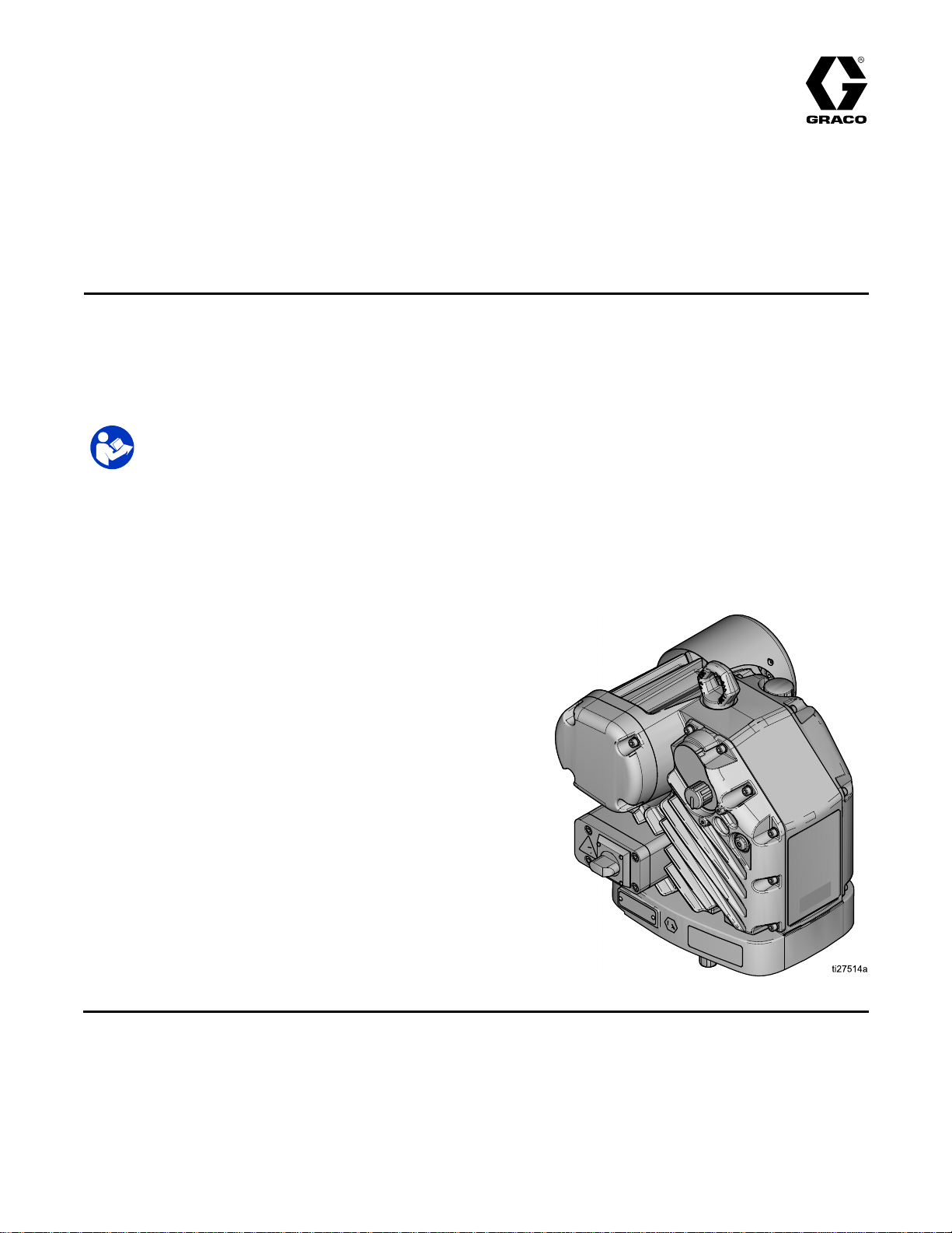
Installation
E60/E50 KingTM Electric Driver
Electric
Electric Electric
For
For For
Seepages3formodelandapprovals
information.
driver
driver driver
professional
professional professional
Important
Important Important
Readallwarningsandinstructionsinthismanualandthesystem
manualbeforeusingtheequipment.Saveallinstructions.
for
for for
3A8119A
EN
application
application application
use
only.
use use
only. only.
Safety
Safety Safety
of
nishing
of of
nishing nishing
Instructions
Instructions Instructions
materials
materials materials
and
protective
and and
protective protective
coatings
coatings coatings
using
King
using using
Sprayers.
King King
Sprayers. Sprayers.
PROVENQUALITY.LEADINGTECHNOLOGY.
Page 2

Contents
Contents Contents
ModelInformation...............................................3
DriverModel................................................3
RelatedManuals................................................3
Warnings...........................................................4
ComponentIdentication.....................................7
Installation..........................................................8
PowerRequirements....................................8
HazardousAreaCablingandConduit
Requirements.................................8
Grounding...................................................9
ConnectPower............................................10
GeneralRepairInformation.................................11
GracoInformation...............................................12
2
3A8119A
Page 3
ModelInformation
Model
Model Model
Driver
Driver Driver
Part
Part Part
24X960AKingDriver
List
List List
•IEC60079–0
•IEC60079–1
•EN60079–0
•EN60079–1
•ANSI/ISA60079–0
•ANSI/UL60079–1
•FM3600
•FM3615
•FM3810
•CSAC22.2No.0.4
•CSAC22.2No.0.5
•CSAC22.2No.30
•CAN/CSAC22.260079–0
•CAN/CSAC22.260079–1
•CAN/CSAC22.2No.61010.1
Standards
of ofofStandards Standards
Information
Information Information
Model
Model Model
Series
Series Series
2575
2575 2575
ExdbIIAT4Gb–5˚C≤Ta≤50C˚
FM15ATEX0060X
IECExFMG15.0035X
Description
Description Description
II2G
Related
Related Related
Manual
Manual Manual
English
English English
3A8124KingE60/E50ElectricDriver
3A8126
311619PumpMountingKitManual
in
in in
Weight
Weight Weight
110lb(50kg)
Explosionproof.ForClass1,Div1,GroupDT4.
Zone1,AExdbIIAT4Gb–5˚C≤Ta≤50C˚
ExdbIIAT4Gb–5˚C≤Ta≤50C˚
FM20CA0054X
Manuals
Manuals Manuals
Description
Description Description
Operation,RepairandTroubleshooting
KingE60/E50ElectricSprayer
3A8119A 3
Page 4
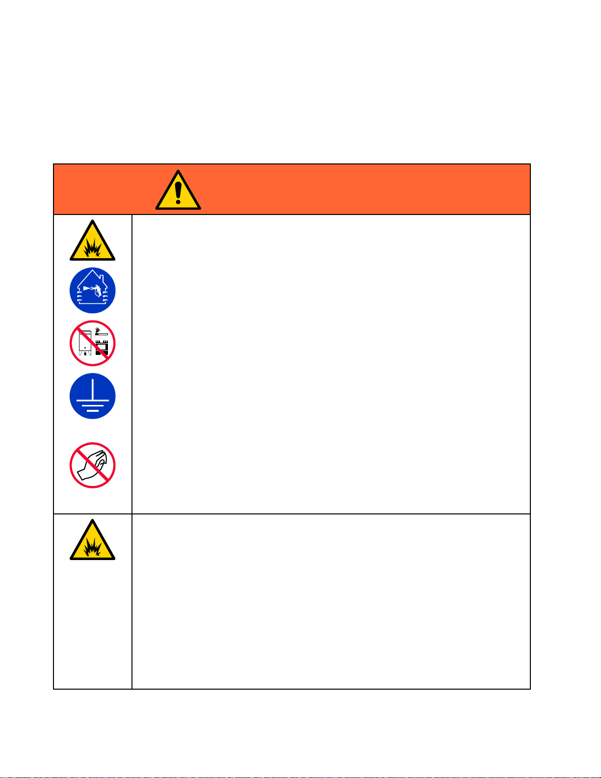
Warnings
Warnings
Warnings Warnings
Thefollowingwarningsareforthesetup,use,grounding,maintenance,andrepairofthisequipment.The
exclamationpointsymbolalertsyoutoageneralwarningandthehazardsymbolsrefertoprocedure-specic
risks.Whenthesesymbolsappearinthebodyofthismanualoronwarninglabels,referbacktothese
Warnings.Product-specichazardsymbolsandwarningsnotcoveredinthissectionmayappearthroughout
thebodyofthismanualwhereapplicable.
WARNING
WARNING WARNING
FIRE
AND
FIRE FIRE
Flammablefumes,suchassolventandpaintfumes,inwork work
Paintorsolventowingthroughtheequipmentcancausestaticsparking.Tohelpprevent
reandexplosion:
•Useequipmentonlyinwellventilatedarea.
•Eliminateallignitionsources;suchaspilotlights,cigarettes,portableelectriclamps,
andplasticdropcloths(potentialstaticsparking).
•Groundallequipmentintheworkarea.SeeGrounding Grounding
•Neversprayorushsolventathighpressure.
•Keepworkareafreeofdebris,includingsolvent,ragsandgasoline.
•Donotplugorunplugpowercords,orturnpowerorlightswitchesonoroffwhen
ammablefumesarepresent.
•Useonlygroundedhoses.
•Holdgunrmlytosideofgroundedpailwhentriggeringintopail.Donotusepailliners
unlesstheyareanti-staticorconductive.
Stop
•Stop Stop
equipmentuntilyouidentifyandcorrecttheproblem.
•Keepaworkingreextinguisherintheworkarea.
EXPLOSION
AND AND
EXPLOSION EXPLOSION
operation
operation operation
immediately
immediately immediately
HAZARD
HAZARD HAZARD
work
area
area area
canigniteorexplode.
Grounding
ifstaticsparkingoccursoryoufeelashock.Donotuse
instructions.
Staticchargemaybuilduponplasticpartsduringcleaningandcoulddischargeandignite
ammablevapors.Tohelppreventreandexplosion:
•Cleanplasticpartsonlyinwellventilatedarea.
•Donotcleanwithadrycloth.
•Donotoperateelectrostaticgunsinequipmentworkarea.
SPECIAL
SPECIAL SPECIAL
•Topreventtheriskofelectrostaticsparking,theequipment’snon-metallicpartsshould
becleanedonlywithadampcloth.
•Thealuminumhousingmaysparkuponimpactorcontactwithmovingparts,whichmay
causereorexplosion.Takeprecautionstoavoidsuchimpactorcontact.
•Allameproofjointsarecriticaltotheintegrityofthedriverasapprovedforhazardous
locationsandarenotrepairableifdamaged.Damagedpartsmustbereplacedonlywith
genuineGracopartswithnosubstitutions.
•ConsultGracoTechnicalAssistanceoryourGracodistributorifdimensionalinformation
ontheameproofjointsisnecessary.
•ConsultGracoTechnicalAssistanceoryourGracodistributorforgenuinereplacement
fasteners.M8x30socket-headcapscrewsofClass12.9steelorbetterwithaminimum
yieldstrengthof1100MPa(160,000psi)areacceptablealternatives.Allsocket-head
capscrewcoverfastenersmustbetorquedto15ft-lb(20.3N•m).
CONDITIONS
CONDITIONS CONDITIONS
FOR
SAFE
FOR FOR
USE
SAFE SAFE
USE USE
4
3A8119A
Page 5

Warnings
WARNING
WARNING WARNING
ELECTRIC
ELECTRIC ELECTRIC
Thisequipmentmustbegrounded.Impropergrounding,setup,orusageofthesystem
cancauseelectricshock.
•Turnoffanddisconnectpoweratmainswitchbeforedisconnectinganycablesand
beforeservicingorinstallingequipment.
•Connectonlytogroundedpowersource.
•Allelectricalwiringmustbedonebyaqualiedelectricianandcomplywithalllocal
codesandregulations.
•Donotexposetorain.Storeindoors.
•Waitveminutesbeforeservicingafterpowerisremoved.
BURN
BURN BURN
Equipmentsurfacesanduidthatisheatedcanbecomeveryhotduringoperation.To
avoidsevereburns:
•Donottouchhotuidorequipment.
MOVING
MOVING MOVING
Movingpartscanpinch,cutoramputatengersandotherbodyparts.
SHOCK
SHOCK SHOCK
HAZARD
HAZARD HAZARD
PARTS
PARTS PARTS
HAZARD
HAZARD HAZARD
HAZARD
HAZARD HAZARD
•Keepclearofmovingparts.
•Donotoperateequipmentwithprotectiveguardsorcoversremoved.
•Pressurizedequipmentcanstartwithoutwarning.Beforechecking,moving,orservicing
equipment,followthePressure Pressure
SKIN
INJECTION
SKIN SKIN
INJECTION INJECTION
High-pressureuidfromgun,hoseleaks,orrupturedcomponentswillpierceskin.This
maylooklikejustacut,butitisaseriousinjurythatcanresultinamputation.Get Get
immediate
immediate immediate
•Donotspraywithouttipguardandtriggerguardinstalled.
•Engagetriggerlockwhennotspraying.
•Donotpointgunatanyoneoratanypartofthebody.
•Donotputyourhandoverthespraytip.
•Donotstopordeectleakswithyourhand,body,glove,orrag.
•FollowthePressure Pressure
checking,orservicingequipment.
•Tightenalluidconnectionsbeforeoperatingtheequipment.
•Checkhosesandcouplingsdaily.Replacewornordamagedpartsimmediately.
surgical
surgical surgical
Pressure
Pressure
HAZARD
HAZARD HAZARD
treatment.
treatment. treatment.
Relief
Relief Relief
Relief
Procedure
Relief Relief
Procedure Procedure
Procedure
Procedure Procedure
whenyoustopsprayingandbeforecleaning,
anddisconnectallpowersources.
Get
3A8119A 5
Page 6

Warnings
WARNING
WARNING WARNING
TOXIC
TOXIC TOXIC
Toxicuidsorfumescancauseseriousinjuryordeathifsplashedintheeyesoron
skin,inhaled,orswallowed.
•ReadSafetyDataSheets(SDSs)toknowthespecichazardsoftheuidsyouare
•Storehazardousuidinapprovedcontainers,anddisposeofitaccordingtoapplicable
PERSONAL
PERSONAL PERSONAL
Wearappropriateprotectiveequipmentwhenintheworkareatohelppreventserious
injury,includingeyeinjury,hearingloss,inhalationoftoxicfumes,andburns.Protective
equipmentincludesbutisnotlimitedto:
•Protectiveeyewear,andhearingprotection.
•Respirators,protectiveclothing,andglovesasrecommendedbytheuidandsolvent
EQUIPMENT
EQUIPMENT EQUIPMENT
Misusecancausedeathorseriousinjury.
FLUID
FLUID FLUID
using.
guidelines.
manufacturer.
OR
FUMES
OR OR
FUMES FUMES
PROTECTIVE
PROTECTIVE PROTECTIVE
MISUSE
MISUSE MISUSE
EQUIPMENT
EQUIPMENT EQUIPMENT
HAZARD
HAZARD HAZARD
•Donotoperatetheunitwhenfatiguedorundertheinuenceofdrugsoralcohol.
•Donotexceedthemaximumworkingpressureortemperatureratingofthelowestrated
systemcomponent.SeeTechnical Technical
•Useuidsandsolventsthatarecompatiblewithequipmentwettedparts.SeeTechnical Technical
Specications
Specications Specications
warnings.Forcompleteinformationaboutyourmaterial,requestSafetyDataSheets
(SDSs)fromdistributororretailer.
•Donotleavetheworkareawhileequipmentisenergizedorunderpressure.
•TurnoffallequipmentandfollowthePressure Pressure
isnotinuse.
•Checkequipmentdaily.Repairorreplacewornordamagedpartsimmediatelywith
genuinemanufacturer’sreplacementpartsonly.
•Donotalterormodifyequipment.Alterationsormodicationsmayvoidagency
approvalsandcreatesafetyhazards.
•Makesureallequipmentisratedandapprovedfortheenvironmentinwhichyouare
usingit.
•Useequipmentonlyforitsintendedpurpose.Callyourdistributorforinformation.
•Routehosesandcablesawayfromtrafcareas,sharpedges,movingparts,andhot
surfaces.
•Donotkinkoroverbendhosesorusehosestopullequipment.
•Keepchildrenandanimalsawayfromworkarea.
•Complywithallapplicablesafetyregulations.
inallequipmentmanuals.Readuidandsolventmanufacturer’s
Technical
Specications
Specications Specications
Pressure
inallequipmentmanuals.
Relief
Relief Relief
Procedure
Procedure Procedure
whenequipment
Technical
6 3A8119A
Page 7

ComponentIdentication
Component
Component Component
Identication
Identication Identication
Ref.
Ref. Ref.
ADriver
CLiftRing
GOilDrainPlug
H
K
L
N
P
SPowerSwitch(Lock-outtag-outequipped)
YElectricalJunctionBox
X
Z
ZZ
Description
Description Description
DriverOutputShaft
OilSightGlass
StatusIndicatorLight(LED)
PressureControlKnob
OilFillCap(vented)
ConduitEntry
ElectricalJunctionBoxCover
GroundScrews
3A8119A
7
Page 8

Installation
Installation
Installation Installation
Installationofthisequipmentinvolvespotentially
hazardousprocedures.Onlytrainedandqualied
personnelwhohavereadandwhounderstand
theinformationinthismanualshouldinstallthis
equipment.
NOTE:
NOTE: NOTE:
information,seeDriverOperationmanual.
Power
Power Power
ForcompleteTechnicalSpecication
Requirements
Requirements Requirements
Improperwiringmaycauseelectricshockorother
seriousinjuryifworkisnotperformedproperly.
Haveaqualiedelectricianperformanyelectrical
work.Besureyourinstallationcomplieswithall
Localcodesandregulations.
Hazardous
Hazardous Hazardous
Requirements
Requirements Requirements
Explosion
Explosion Explosion
Allelectricalwiringinthehazardousareamustbe
encasedinClassI,DivisionI,GroupDapproved
explosion-proofconduit.FollowallNational,State,
andLocalelectriccodes.
Aconduitsealisrequiredwithin18in.(457
mm)ofthedriverfortheUSandCanada.See
ConnectPower,page10.
Allcablesmustberated70°Cminimum.
Flame
Flame Flame
Useappropriateconduit,connectors,andcable
glandsratedforATEXII2G.FollowallLocalcodes
andregulations.
Allcableglandsandcablesmustberated70°C
minimum.
Proof
Proof Proof
Area
Area Area
Proof
Proof Proof
(ATEX)
(ATEX) (ATEX)
Cabling
Cabling Cabling
and
Conduit
and and
Conduit Conduit
Seethetablebelowforpowersupplyrequirements.
Thedriverrequiresadedicatedcircuitprotectedwith
acircuitbreaker.
Model
Model Model
Theprotectiveearthinggroundconductormustbe
equaltothephaseconductors.
Voltage
Voltage Voltage
200–240Vac150/6015A 24X960
100–120Vac150/6025A
Phase
Phase Phase
Hz
Hz Hz
Amperage
Amperage Amperage
8 3A8119A
Page 9

Grounding
Grounding Grounding
Thisequipmentmustbegroundedtoreducethe
riskofstaticsparkingandelectricshock.Electric
orstaticsparkingcancausefumestoigniteor
explode.Impropergroundingcancauseelectric
shock.Groundingprovidesanescapewireforthe
electriccurrent.
Driver:
Driver: Driver:
Thedriverisgroundedthroughthepowercord.
Installation
Driver
Driver Driver
PumpGroundWire–Twogroundterminalsare
providediflocalcoderequiresredundantgrounding
connections.
Loosenthegroundscrew(ZZ)andattachaground
wire(Gracopart244524–notsupplied).Tightenthe
groundscrewsecurely.Connecttheotherendofthe
groundwiretoatrueearthground.
(optional
(optional (optional
secondary):
secondary): secondary):
3A8119A 9
Page 10

Installation
1
2
3
4
Connect
Connect Connect
Power
Power Power
Improperwiringmaycauseelectricshock,re
andexplosion,orotherseriousinjuryifwork
isnotperformedproperly.Haveaqualied
electricianperformanyelectricalwork.Besure
yourinstallationcomplieswithallNational,State
andLocalsafetyandrecodes.
1.Shutoffthefusedsafetyswitch(B)andfollow
theappropriatelock-out/tag-outprocedures.
Typicalxedinstallationforwallmounted
systemsshownbelow:
4.Installincomingpowerwiresintothedisconnect
terminalslabeled2T1and4T2,andtorqueto7
in-lb(0.8N•m).
5.Reinstalljunctionboxcover(Z)andscrews(J).
Torquescrewsto15–20ft-lb(21–27N•m).
NOTE:
NOTE: NOTE:
Onewireisinstalledinterminals1L1and
3L2.
Makesurewiresarenotpinchedwhen
re-installingcovers.Wireswillbedamaged
andcreateanelectricalhazardand/orreand
explosionhazardifpinched.
Disconnect
Disconnect Disconnect
2.Toinstallwiring,locatetheelectricaljunctionbox
(Y).Removefourscrews(J)andjunctionbox
cover(Z).Wireswillalreadybeinstalledinthe
frontsideofthedisconnectinterminalslabeled
Block
Terminals
Block Block
Terminals Terminals
Tightendisconnectblockterminalsto7in-lb
(0.8N•m).Donotover-tighten.
Tightencoverscrewsto15ft-lb(20.3N•m).
Aconduitseal(D)isrequiredwithin18in.
(457mm)ofthedriverfortheUSandCanada.
15in-lbmaximum(terminalbushings)
†Conduitnotsupplied.
‡Powercordnotsupplied.
1L1and3L2.
3.Connectthegroundwiretothelabeledground
screwinthebackofthejunctionbox.See
Grounding,page9.
10 3A8119A
Page 11

GeneralRepairInformation
General
General General
Information
Information Information
NOTE:
NOTE: NOTE:
instructions.
SeeDriverRepairmanualforspecic
Toavoidelectricshock,reandexplosionhazard,
and/orinjuryfrommovingpartshazard,turnoff
equipmentpowerandshutoffpoweratthemain
circuitbreakerbeforerepairing.Wearappropriate
protectiveequipmentwheninworkarea.Waitve
minutesbeforeservicing.
Makesurewiresarenotpinchedwhenre-installing
covers.Wireswillbedamagedandcreatean
electricalhazardand/orreandexplosionhazard
ifpinched.
Repair
Repair Repair
NOTE:
NOTE: NOTE:
Gracodistributorforgenuinereplacementfasteners.
M8x30socket-headcapscrewsofClass12.9steel
orbetterwithaminimumyieldstrengthof1100
MPa(160,000psi)areacceptablealternatives.All
socket-headcapscrewcoverfastenersmustbe
torquedto15ft-lb(20.3N•m).
ConsultGracoTechnicalAssistanceoryour
3A8119A
11
Page 12

Graco
Graco Graco
NOTE:
NOTE: NOTE:
ForthelatestinformationaboutGracoproducts,visitwww.graco.com.Forpatentinformation,seewww.graco.com/patents.
To
place
To To
place place
1-800-328-0211Fax: Fax:
Allwrittenandvisualdatacontainedinthisdocumentreectsthelatestproductinformationavailableatthetimeofpublication.
Gracoreservestherighttomakechangesatanytimewithoutnotice.OriginalInstructions.ThismanualcontainsEnglish.MM3A8119 3A8119
Information
Information Information
ForGracoWarrantyinformationseeDriverOperationmanual.
order,
an ananorder, order,
contactyourGracoDistributororcalltoidentifythenearestdistributor.Phone: Phone:
Fax:
612-378-3505
Graco
Headquarters:
Graco Graco
Headquarters: Headquarters:
GRACO
GRACO GRACO
INC.
AND
INC. INC.
AND AND
Copyright
Copyright Copyright
2020,
2020, 2020,
MinneapolisInternational International
SUBSIDIARIES
SUBSIDIARIES SUBSIDIARIES
Graco
Inc.
Graco Graco
All
Inc. Inc.
All All
International
P.O.
BOX
• ••P.O. P.O.
BOX BOX
Graco
manufacturing
Graco Graco
manufacturing manufacturing
www.graco.com
RevisionA–October2020
Phone:
612-623-6921or ororToll Toll
Ofces:
Ofces: Ofces:
1441
1441 1441
Belgium,China,Japan,Korea
MINNEAPOLIS
• ••MINNEAPOLIS MINNEAPOLIS
locations
locations locations
MN
55440-1441
MN MN
55440-1441 55440-1441
are
registered
are are
registered registered
to totoISO ISO
USA
• ••USA USA
ISO
9001.
9001. 9001.
Toll
Free:
Free: Free:
3A8119
 Loading...