

Page 1
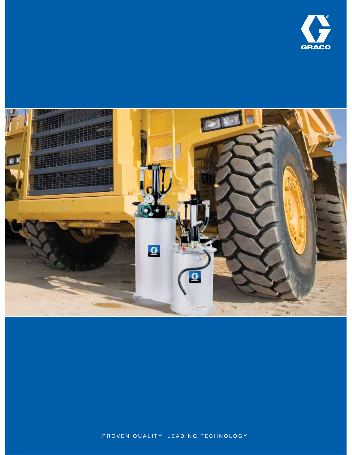
Dyna-Star® 10:1
Dyna-Star® 10:1
High Ratio Hydraulically-Powered Lubrication Pump
Available Electronically Only
Long-lasting, fl exible design saves money and is easy to use and install
• Achieve full pressure performance by safely tapping low pressure hydraulics
• Pre-packaged modules ready-to-work with both injector and divider valve systems
• Multiple pump and accessory options for use with refi nery drum and custom tank installations
• Self-lubricating for long life and reliable operation
• Ultra-quiet hydraulic motor—no need for add-on muffl ers
• High effi ciency motor design uses less hydraulic oil
Page 2
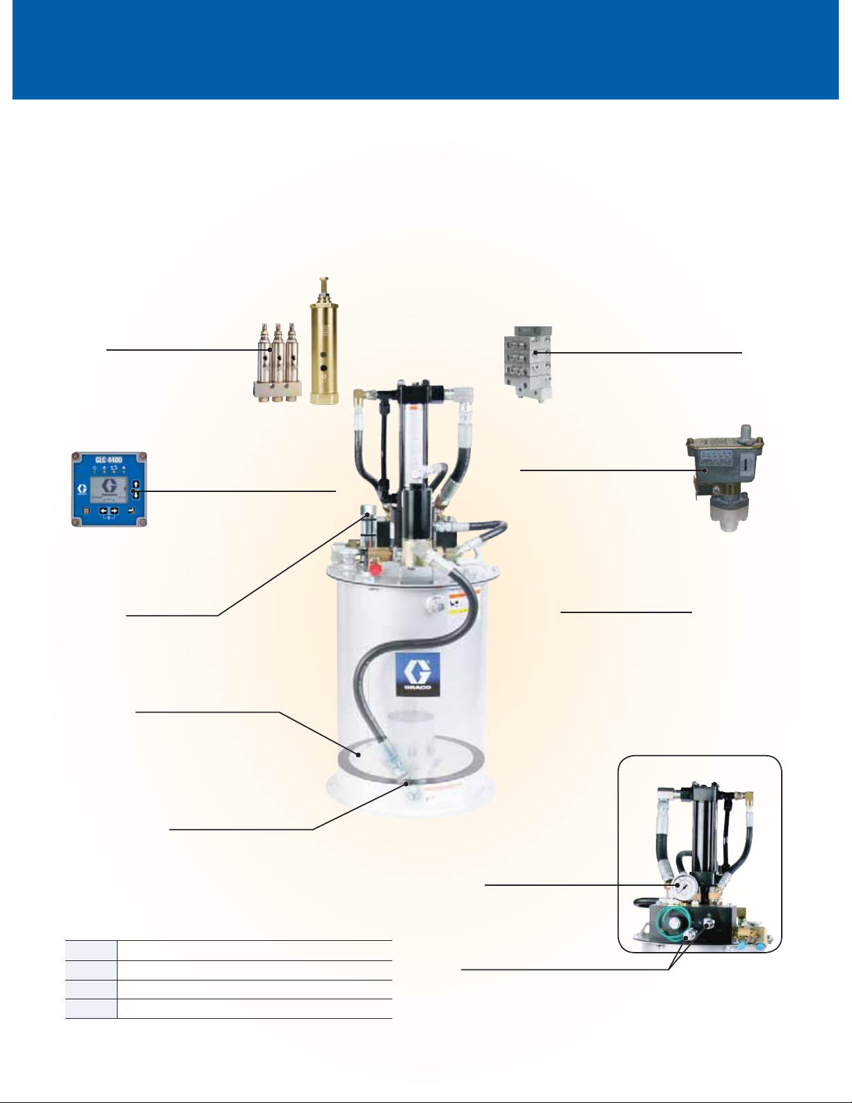
Graco® Quality by Design
Superior System Performance
Heavy-duty construction and mining equipment rely on fresh lubricant to fl ush contaminants from critical pivot points.
An automatic lubrication system from Graco provides constant lube replenishment, preventing expensive and catastrophic
component failures. Divider valves and injectors accurately distribute lubricant to multiple lube points and are designed to
accept a variety of system accessories which include electronic controllers, pressure switches and level indicators.
GL-1 and Gl-11 Injectors
• Exclusive seal design for up to
30% longer life
• Field adjustable output for most
every application
Rugged Digital Controller
Full featured performance—time- or
pressure-based control to monitor reservoir
levels and system pressure
Level Indicator
• Positive, at-a-glance indication of
reservoir lubrication level
• Auto shut-down when low level
is reached
Follower Plate
Innovative design forces grease into
the pump for consistent operation
Trabon® Divider Valve Assembly
• Accurately meters lubrication to each point
• Add performance indicators to ensure vital
components have been lubricated
Pressure Switch
Lets the controller know when optimum
system pressure is reached ensuring
complete lubrication cycle
Field-Proven Graco Fire-Ball®
Grease Pump Lower
Double-acting piston design—the industry
standard for long life
For optimal system performance
NLGI #1 grease is recommended
Center-Feed
Vent and Refill Port
Located below follower plate for
trouble-free venting and refilling
Module and Kit Accessories
247700 Follower plate for 60 lb (27 kg) and 90 lb (41 kg) modules
244023 Level indicator for 60 lb (27 kg) and 90 lb (41 kg) modules*
24B591 GLC 4400, 12/24 VDC controller
115124 Pressure switch
* Follower plate 247700 required for level indicator 244023 to function
Detail of back side of module assembly.
Built-In Gauge
Conveniently monitor hydraulic
output pressure
Pressure and Flow Control
Ability to adjust pressure and flow puts
you in control
Page 3

Typical Applications
Ordering Information
Mobile
• Front-end loaders - 12 cu. yd. or higher
• Mining trucks - 100 ton capacity or higher
• Shovel fronts
• Drag lines
• Bucket wheel excavators
Stationary
• Cement plant
• Jaw and gyratory crushers
• Grinding mill seals
• Mineral sizers
• Ship loaders - slew bearings
• Sludge pumps
DYNA-STAR 10:1 MODULES AND KITS
247574 Dyna-Star 10:1 60 lb (27 kg) Pump Module - Injector - Overall height 35.15 in (842mm).
247706 Dyna-Star 10:1 60 lb (27 kg) Pump Kit - Divider Valve (DV) - Overall height 35.15 in (842mm).
247444 Dyna-Star 10:1 90 lb (41 kg) Pump Module - Injector - Overall height 42.75 in (1086 mm).
247707 Dyna-Star 10:1 90 lb (41 kg) Pump Kit - DV - Overall height 42.75 in (1086 mm). Includes
247902 Pressure relief kit for 247706 and 247707
312349 Manual for 247574, 247706, 247444, 247707
Includes pump (247540), reservoir assembly (247575), hydraulic control assembly (247538)
and vent valve assembly (243170) fully assembled.
Includes pump (247540), reservoir assembly (247575) and hydraulic control assembly
(247538) not assembled.
Includes pump (247443), reservoir assembly (241486), hydraulic control assembly (247538)
and vent valve assembly (243170) fully assembled.
pump (247443), reservoir assembly (241486) and hydraulic control assembly (247538) not
assembled.
Maximum fl uid output for modules and kits = 3,500 PSI (241 bar)
DYNA-STAR 10:1 REFINERY DRUM AND CUSTOM TANK APPLICATIONS
Description Refi nery Drums Custom Tank Applications
Weight lbs (kg) 120 (55) 400 (180) 60 (27) 60 (27) 120 (55) 120 (55) 400 (180) 400 (180)
Divider Valve (DV) or
Injector Based
Pump 247443 247450 247540 247540 247443 247443 247450 247450
Hydraulic Control (1) 247705 247705 247538 247538 247538 247538 247538 247538
Vent Valve 243170 243170 243170
Cover 247703 247704
Follower Plate 247701 247702
Pump Gasket 15M442 15M442 15M442 15M442 15M442 15M442 15M442 15M442
Custom Tank Kit (2) 247970 247456 247457
(1) Hydraulic control assembly (247705) includes longer hoses to enable remote mounting.
(2) Kits include pump (24750, 247443 or 247450), hydraulic control assembly (247538), vent valve (243170) and pump gasket (15M442).
DV DV Injector DV Injector DV Injector DV
GL INJECTORS
114901 One GL-1 injector and manifold
114902 Two GL-1 injectors and manifold
114903 Three GL-1 injectors and manifold
114904 Four GL-1 injectors and manifold
114905 Five GL-1 injectors and manifold
114909 Replacement GL-1 injector
24A918 GL-11 injector
FIREBALL 300 AND DYNA-STAR 5:1 MODULES & ACCESSORIES
241573 Fireball 300, 50:1 90 lb (41 kg) Pump Module. Includes pump (239887), reservoir assembly
241485 Follower plate (fi ts 241573).
243159 Dyna-Star 5:1 90 lb (41 kg) Pump Module. Includes pump (224751), reservoir assembly
243191 Follower plate (fi ts 243159).
See Lubrication Equipment Buyer’s Guide section 14 for more information.
(241486) and vent valve assembly (241572).
(241486), hydraulic control assembly (243501) and vent valve assembly (243170).
Page 4

Technical Specifi cations
8000
(552)
6000
(414)
4000
(276)
2000
(138)
0
1.5
(1.1)
2.0
(1.5)
1.0
(0.7)
0.5
(0.4)
0.0
0.25 0.50 0.75 1.00 1.25
(0.11) (0.23) (0.34) (0.45) (0.57)
cycles/min
Pressure - PSI (bar)
Input Hydraulic Horsepower (kw)
60 0153045
B
C
D
A
Test Fluid: NLGI #1 grade grease
Flowrate–lb per min (kg per min)
600 psi hydraulic inlet pressure
A
300 psi hydraulic inlet pressure
B
Hp (600 psi hydraulic input)
C
Hp (300 psi hydraulic input)
D
DYNA-STAR 10:1 PUMPS
Part Number 247540 247443 247450
Drum Size 60 lb (27 kg) 120 lb (55 kg) 400 lb (180 kg)
Overall Pump Length 33.9 in (861 mm) 41.5 in (1054 mm) 48.5 in (1232 mm)
Pump Lower Length 19.75 in (501 mm) 26.75 in (679 mm) 33.75 in (857 mm)
Maximum Hydraulic
Input Pressure
Maximum Hydraulic
Fluid Input Volume
Maximum Flow
Output Rate
Maximum CPM 60 60 60
Maximum Fluid
Output Pressure
Hydraulic Supply Inlet 3/4"–16 JIC (37º Flare) 3/4"–16 JIC (37º Flare) 3/4"–16 JIC (37º Flare)
Hydraulic Return
Outlet
Fluid Outlet 1/2" npt 1/2" npt 1/2" npt
Maximum Incoming
Hydraulic Fluid Temp.
312350 Manual for 247540, 247443, 247450
600 psi (41 bar) 600 psi (41 bar) 600 psi (41 bar)
3 gpm (11.4 lpm) 3 gpm (11.4 lpm) 3 gpm (11.4 lpm)
1.1 lb/min (0.5 kg/min) 1.1 lb/min (0.5 kg/min) 1.1 lb/min (0.5 kg/min)
7500 psi (517 bar) 7500 psi (517 bar) 7500 psi (517 bar)
3/4" npt 3/4" npt 3/4" npt
200ºF (93ºC) 200ºF (93ºC) 200ºF (93ºC)
ABOUT GRACO
Founded in 1926, Graco is a world leader
in fl uid handling systems and components.
Graco products move, measure, control,
dispense and apply a wide range of
fl uids and viscous materials used in
vehicle lubrication, commercial and
industrial settings.
The company’s success is based on its
unwavering commitment to technical
excellence, world-class manufacturing and
unparalleled customer service. Working
closely with qualifi ed distributors, Graco
offers systems, products and technology
that set the quality standard in a wide
range of fl uid handling solutions.
Graco provides equipment for spray fi nishing,
protective coating, paint circulation,
lubrication, and dispensing sealants and
adhesives, along with power application
equipment for the contractor industry.
Graco’s ongoing investment in fl uid
management and control will continue to
provide innovative solutions to a diverse
global market.
TYPICAL PUMP PERFORMANCE
Call today for product information or talk to a Graco
representative at 1.800.533.9655 or visit us online at
www.graco.com.
©2008-2010 Graco Inc. 338973 Rev. C 1/00. All other brand names or marks are used for identifi cation purposes and are trademarks of their
respective owners. All written and visual data contained in this document are based on the latest product information available at the time of
publication. Graco reserves the right to make changes at any time without notice.
 Loading...